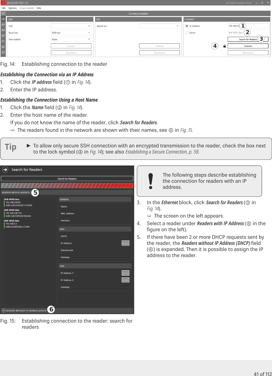
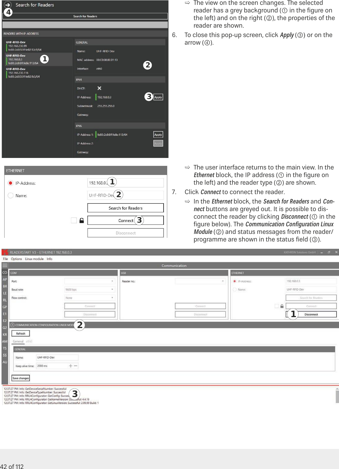
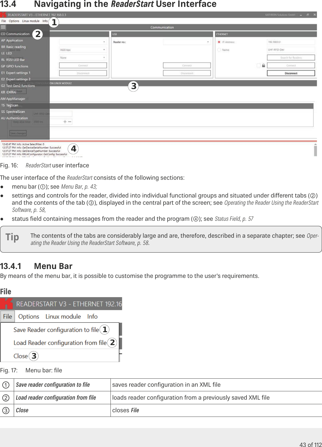
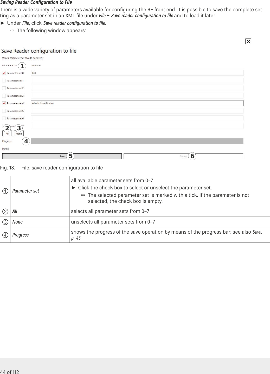
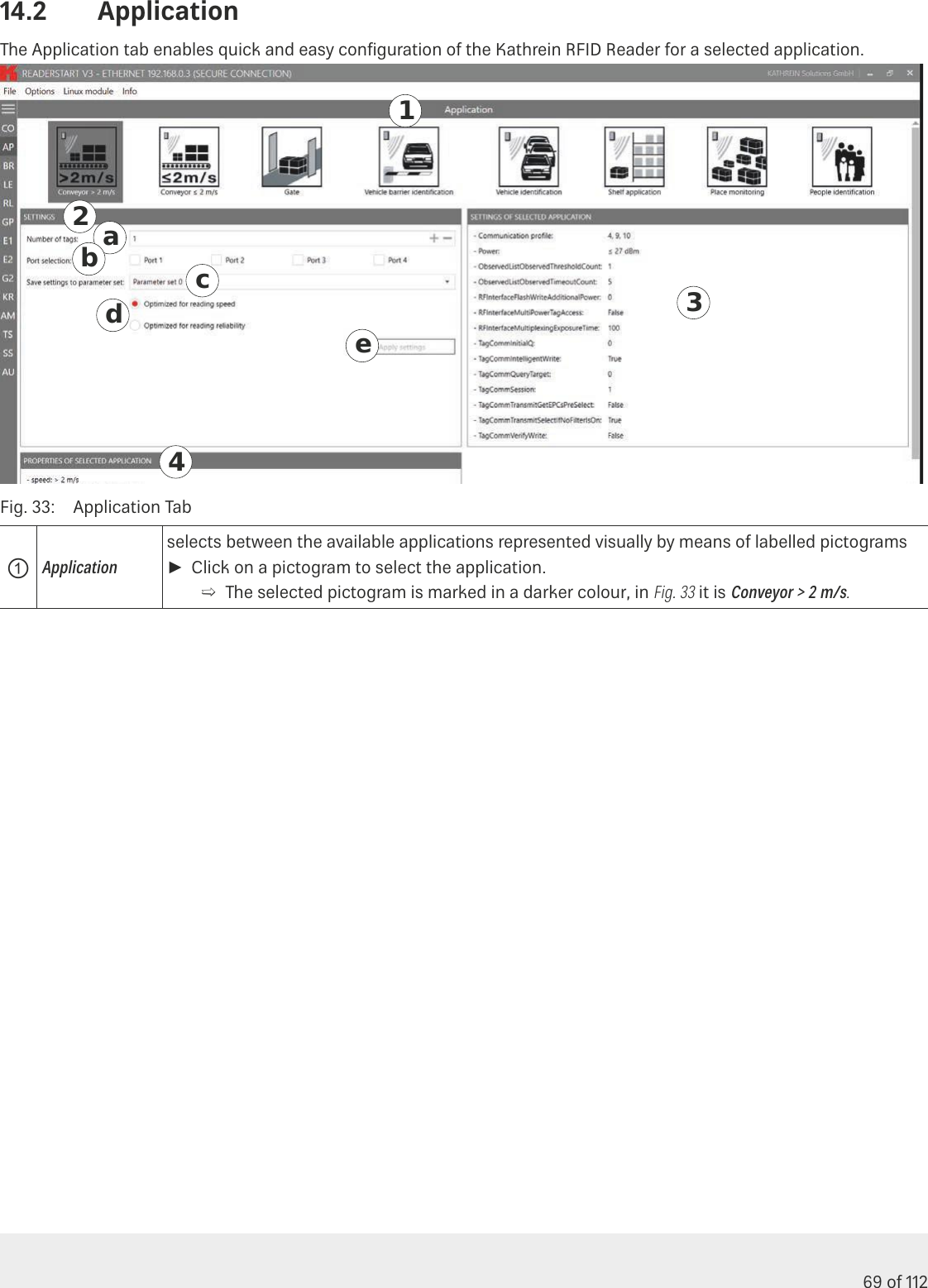
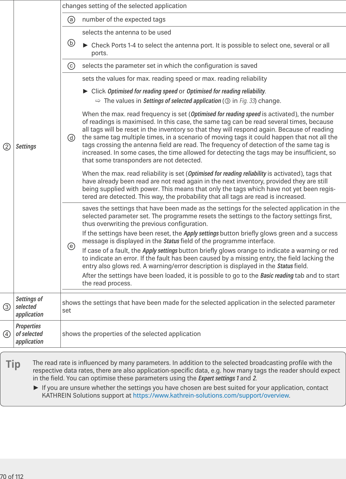
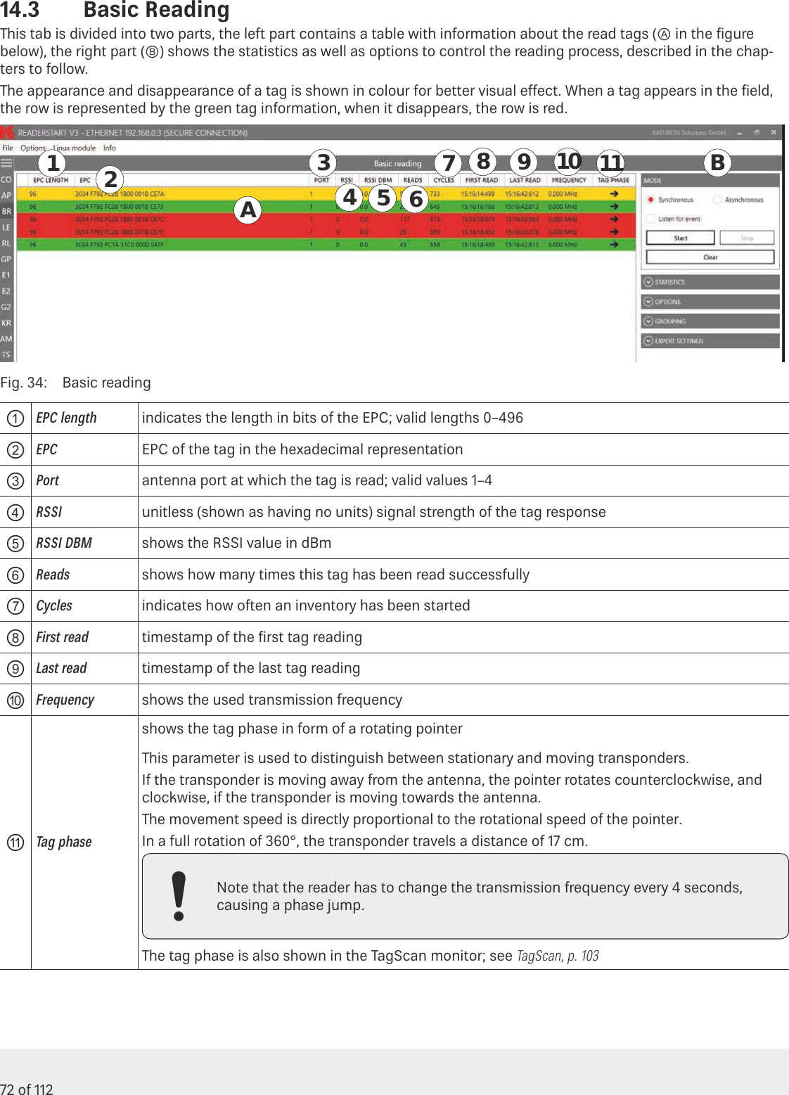
KATHREIN Sachsen ARU3400 Part 15 Spread Spectrum Transmitter User Manual Installation Guide
KATHREIN Sachsen GmbH Part 15 Spread Spectrum Transmitter Installation Guide
UserManual.wiki
>
KATHREIN Sachsen
>
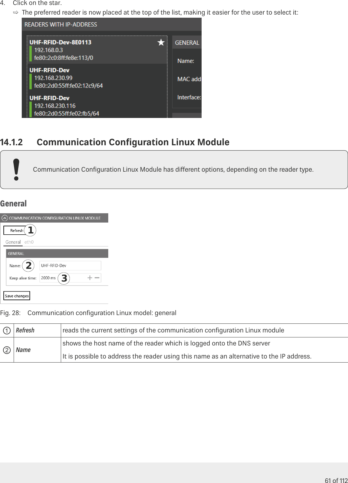
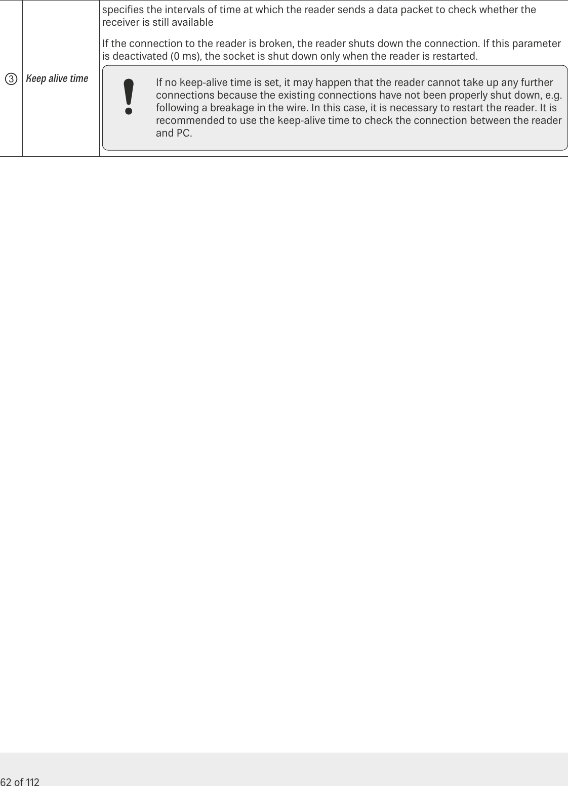
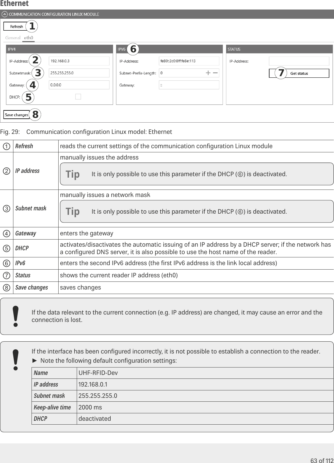
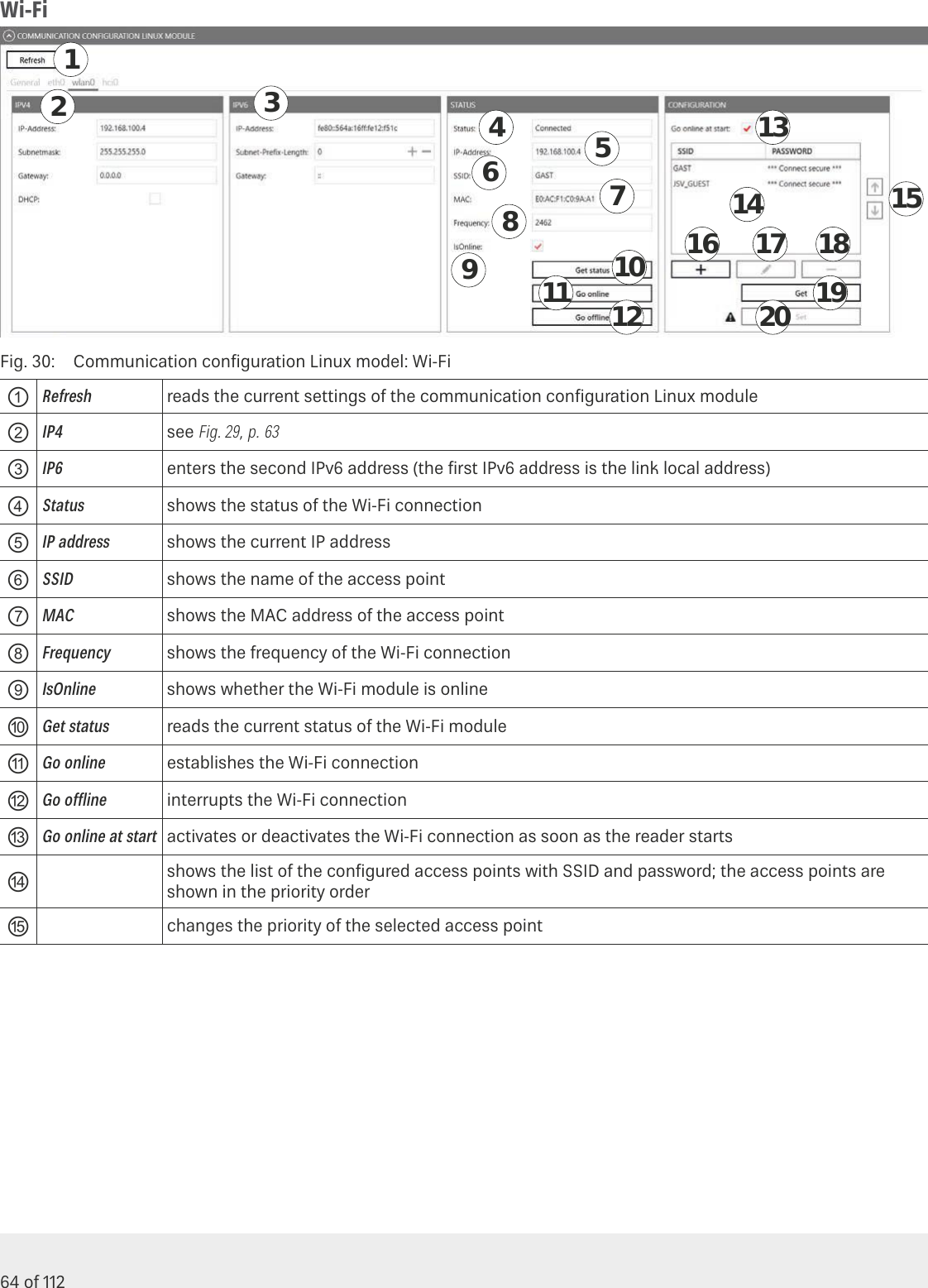
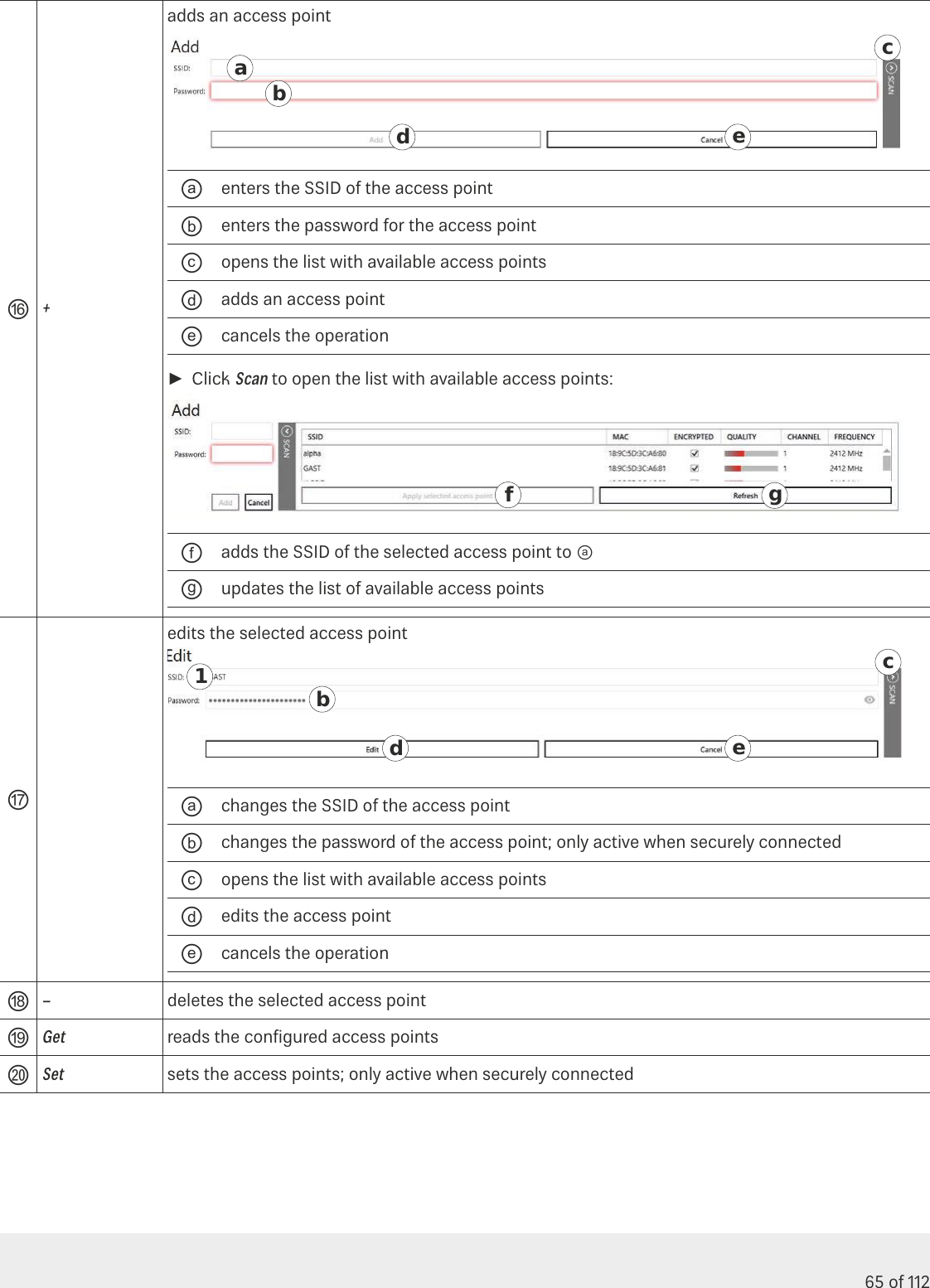
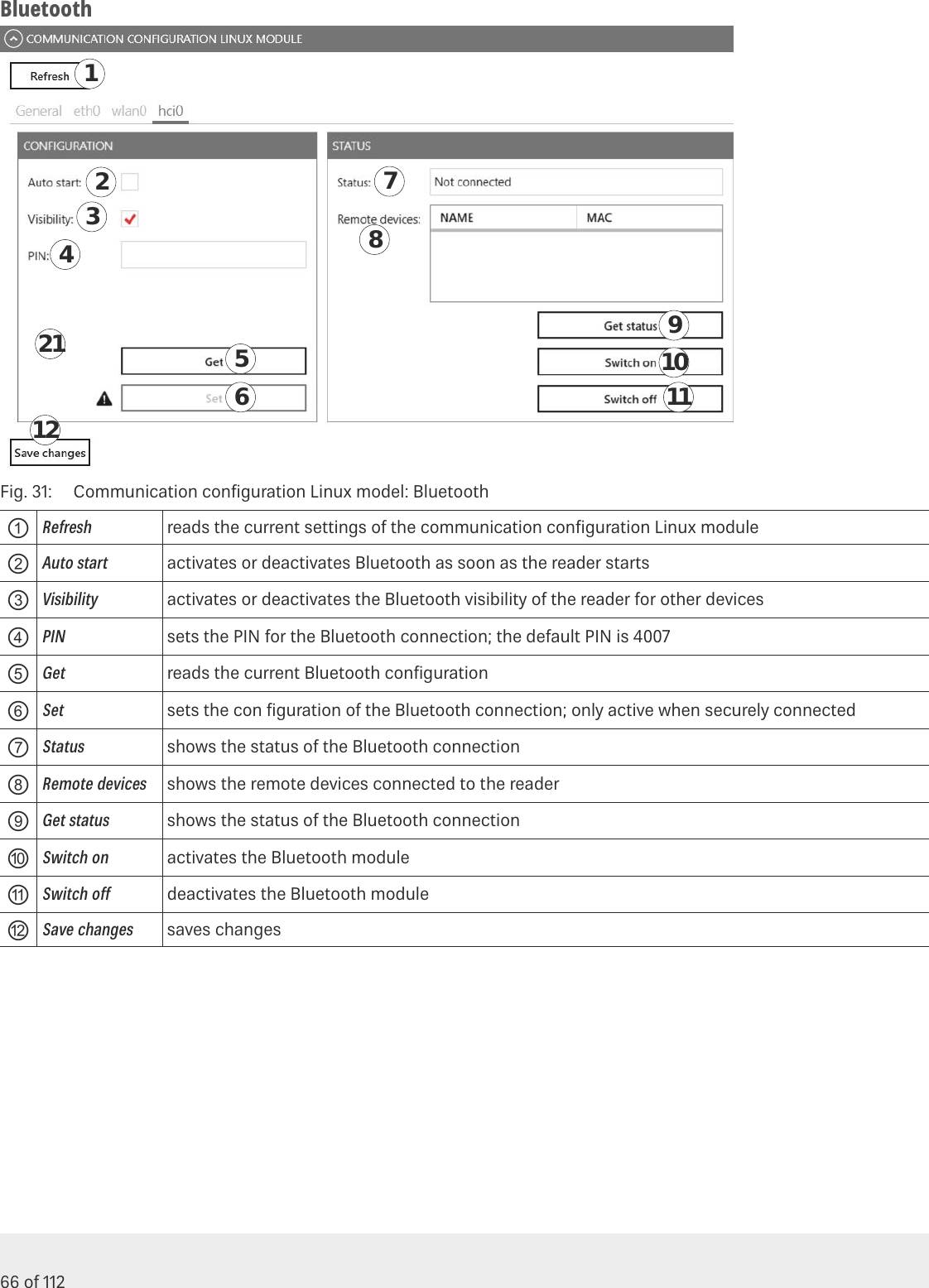
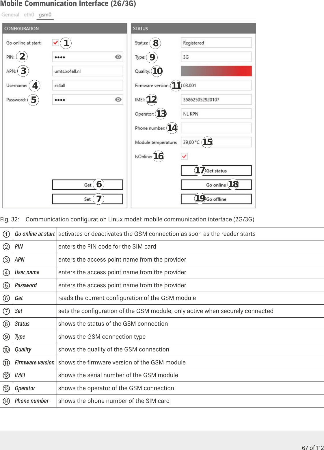
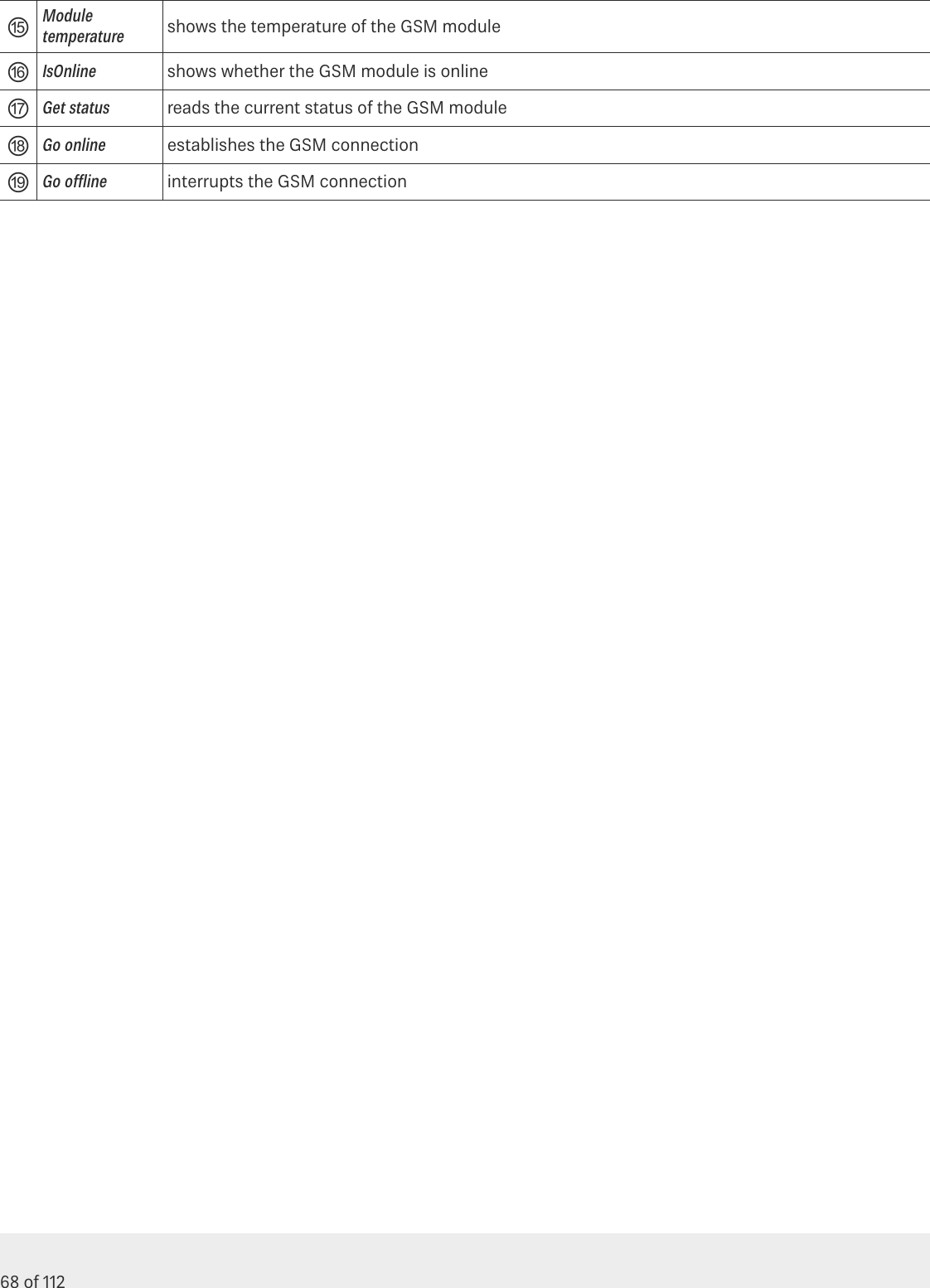
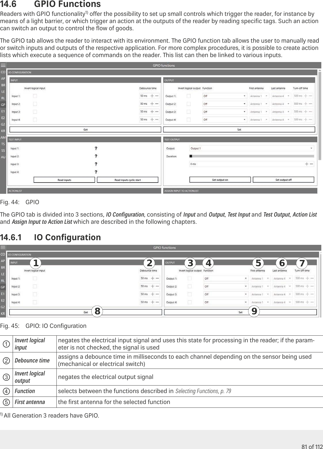
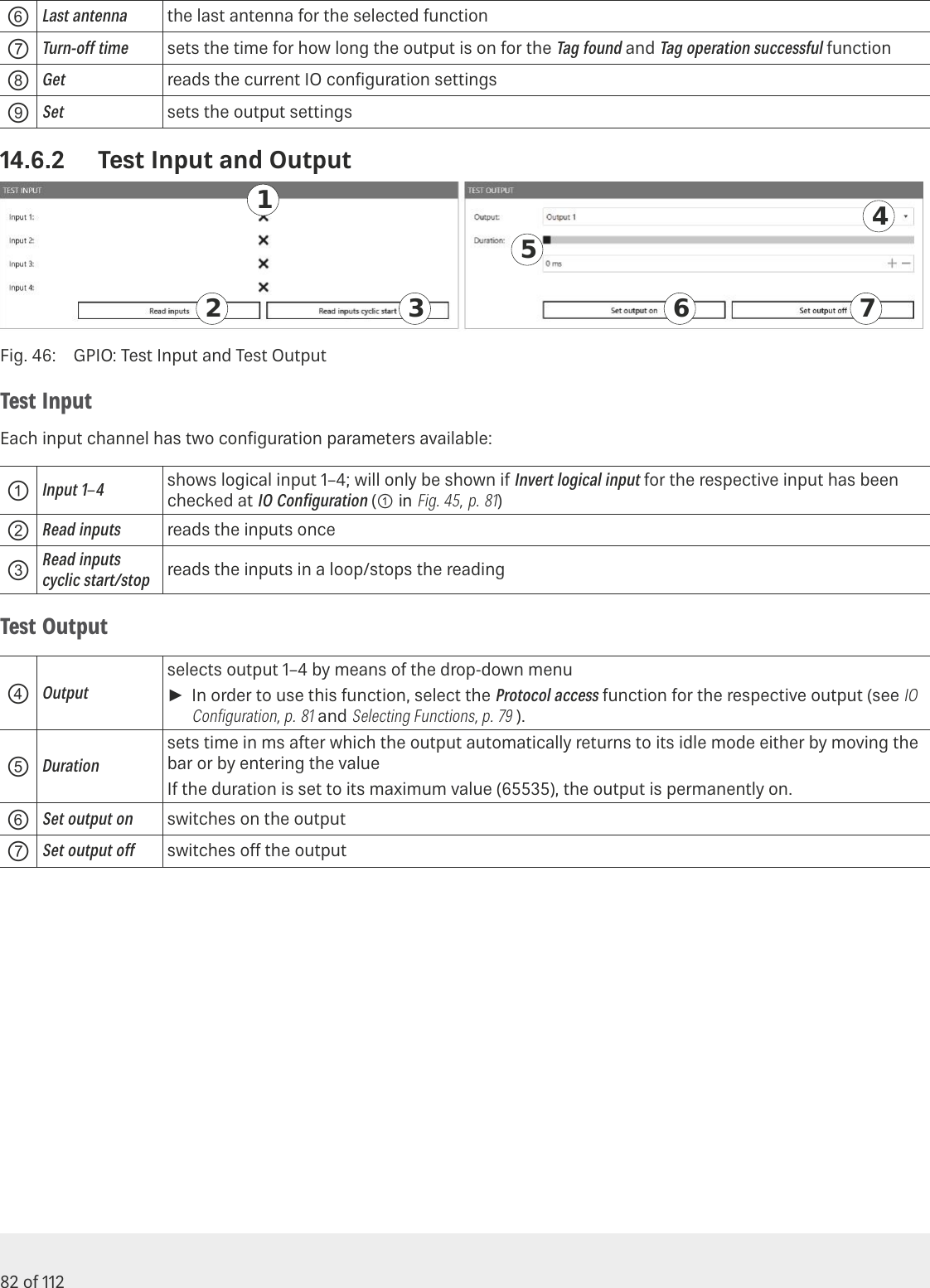
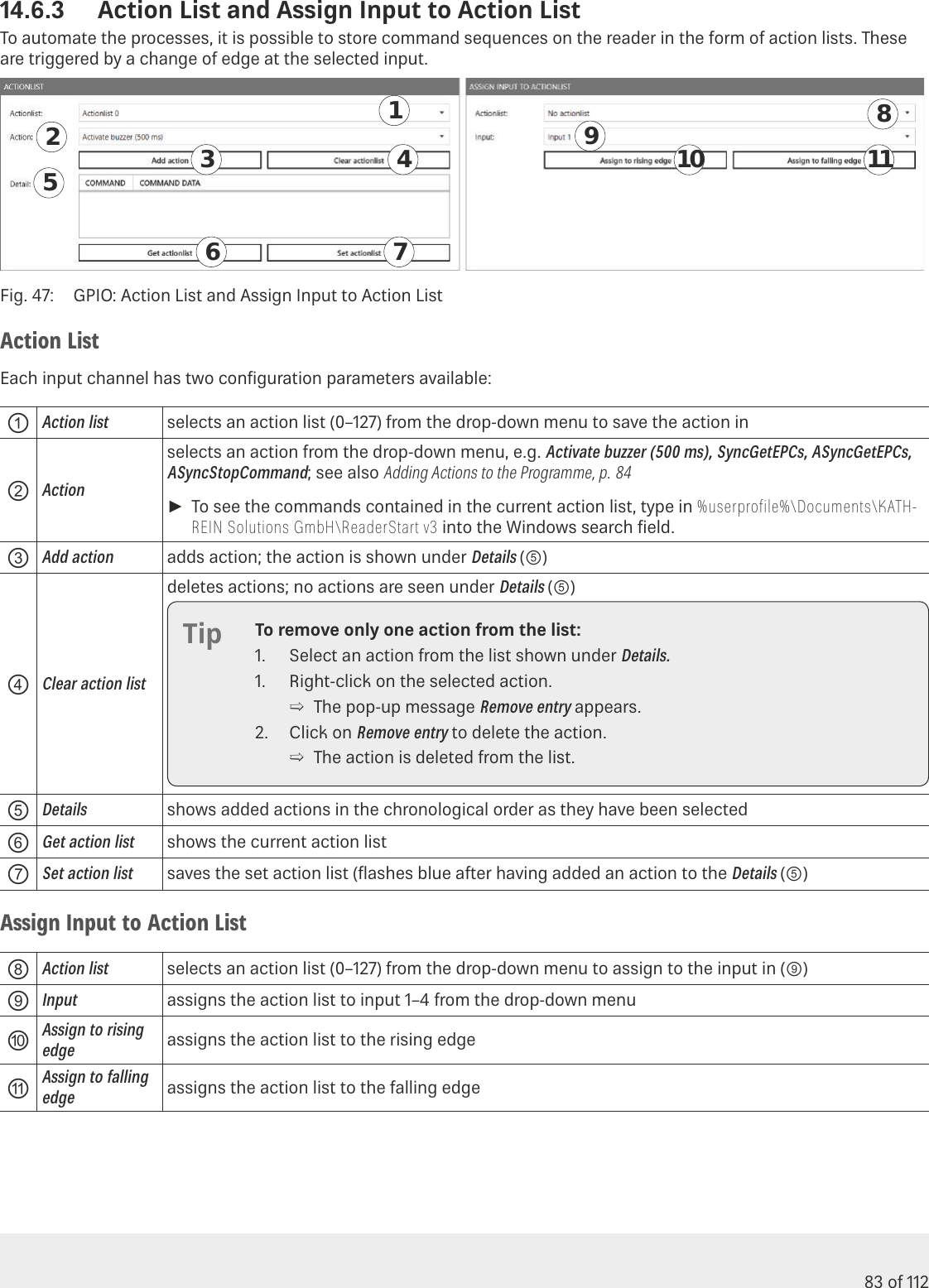
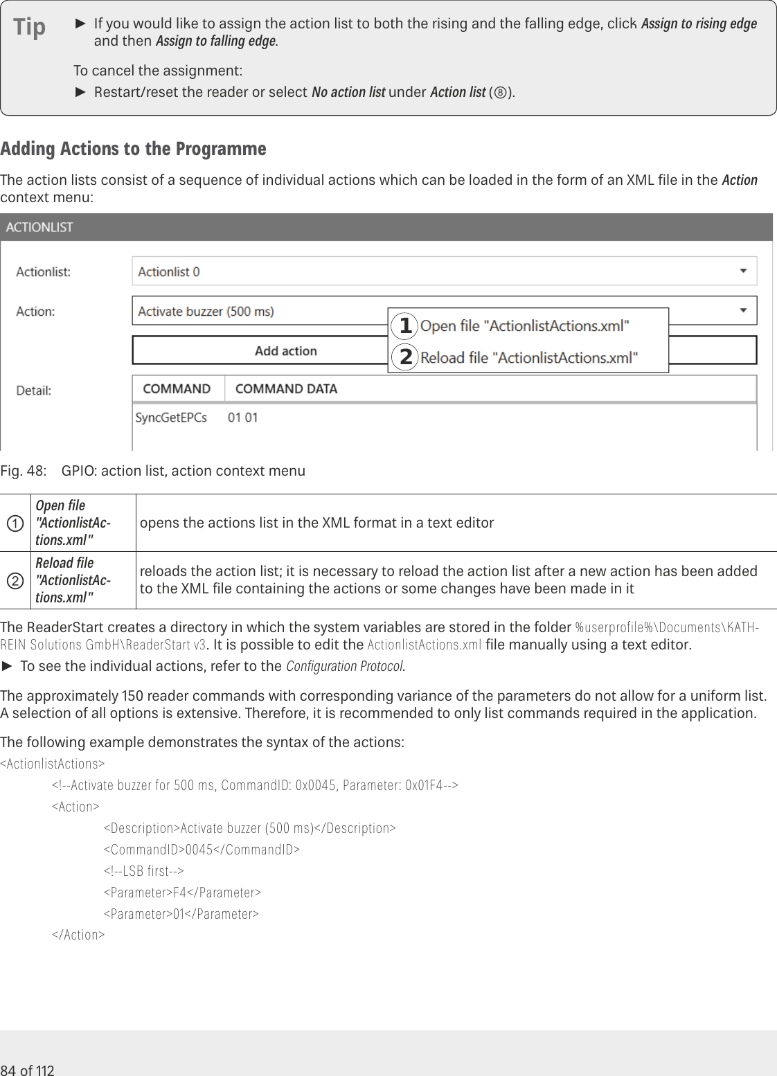
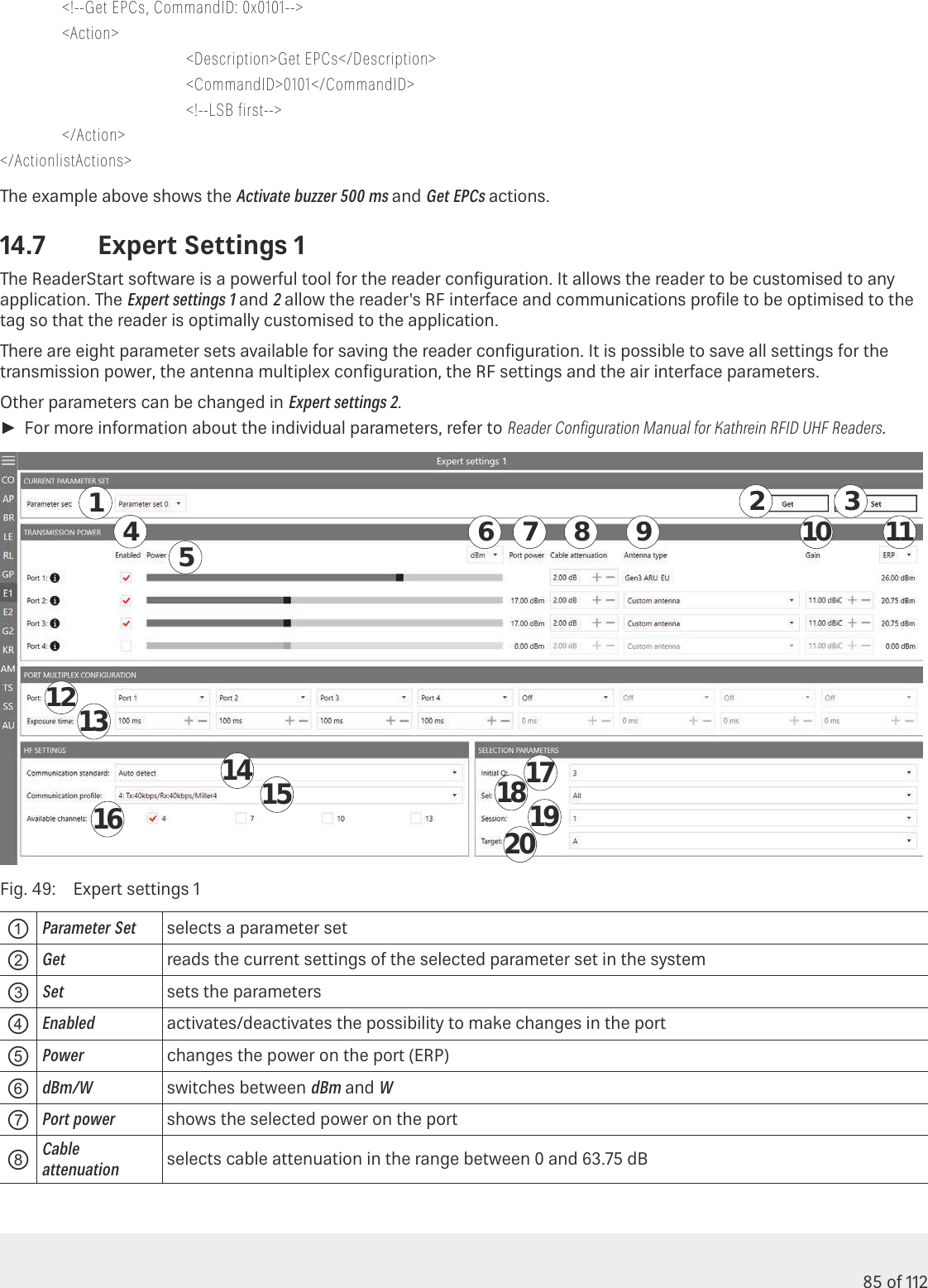
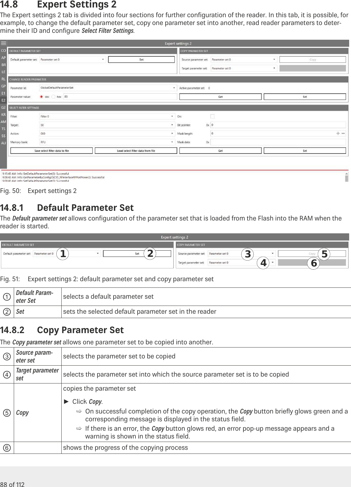
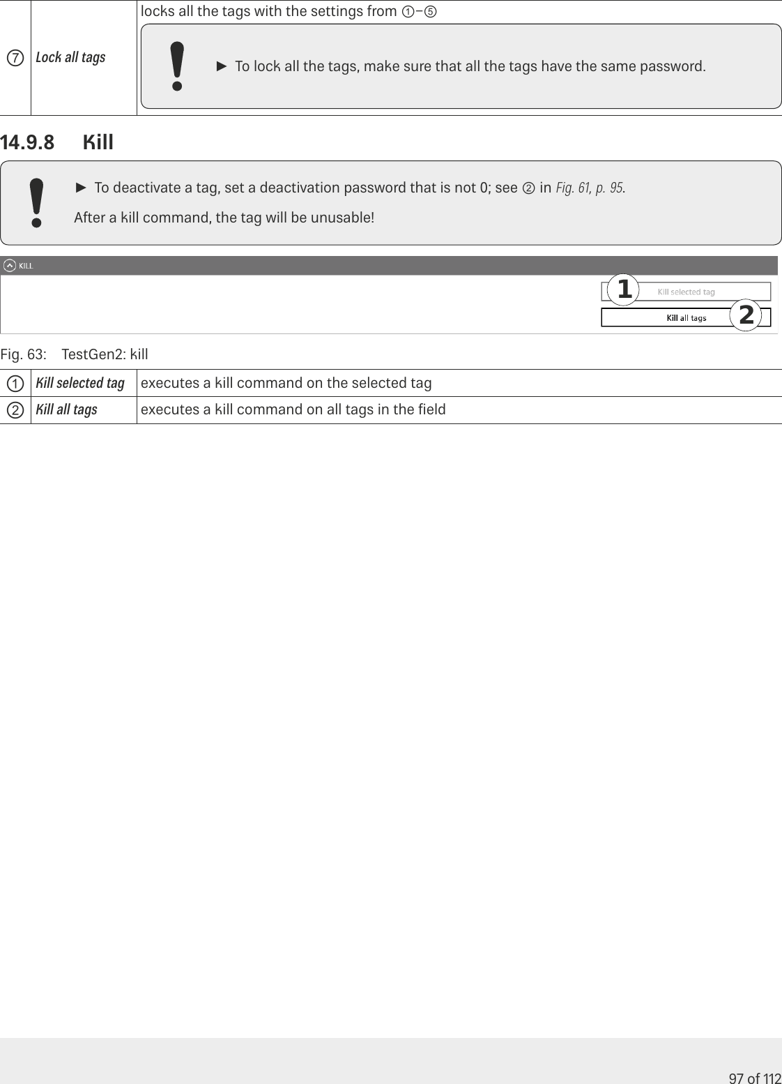
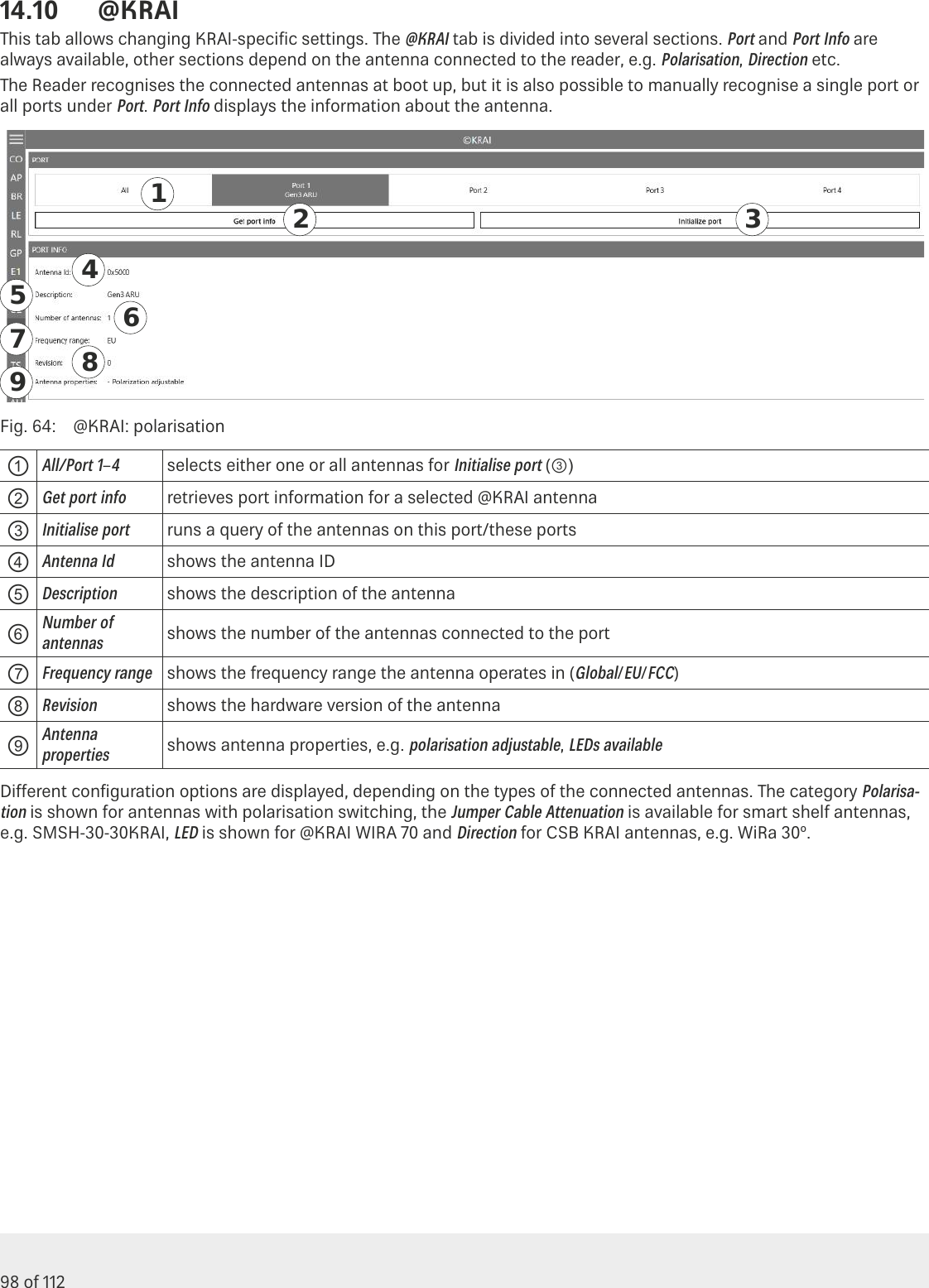
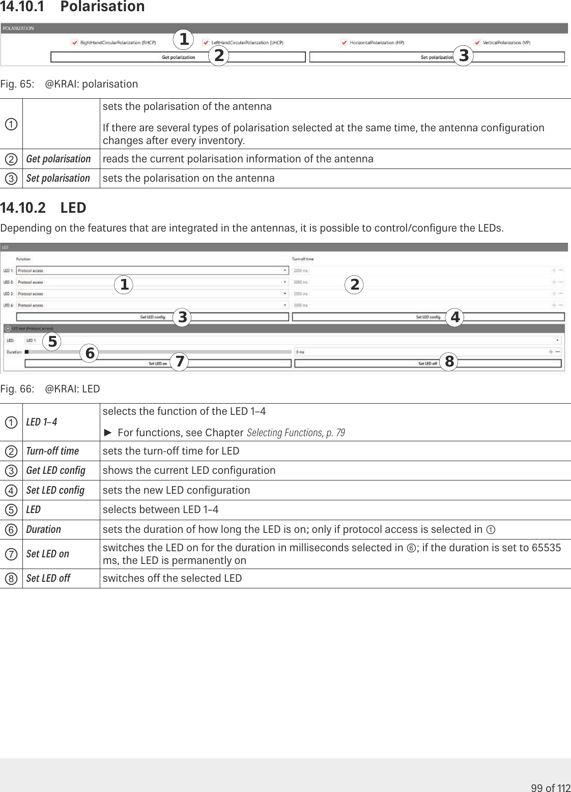
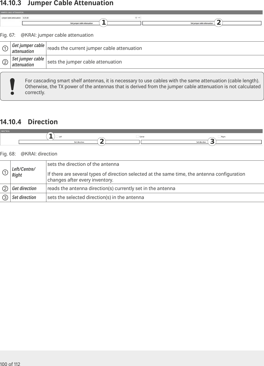
ARU3400 User Manual
Installation Guide
Navigation menu
Upload a User Manual
Namespaces
Wiki Guide
HTML
PDF
Info
Views
User Manual
Discussion / Help
Navigation