KATHREIN Sachsen ARU3400 Part 15 Spread Spectrum Transmitter User Manual Installation Guide
KATHREIN Sachsen GmbH Part 15 Spread Spectrum Transmitter Installation Guide
Installation Guide
User Guide Reader
Generation 3
English
Kathrein RFID UHF Readers
IMPORTANT
Read carefully
before use!

2 of 112
Copyright © 2017 Kathrein Solutions GmbH
All rights reserved. No part of this document may be reproduced, distributed, stored in a retrieval system, translated into
any language or computer language or transmitted in any form or by any means, electronic, mechanical, photocopying,
recording or otherwise, without the prior written permission of Kathrein Solutions GmbH.
Kathrein Solutions GmbH accepts no liability for omissions or inaccuracies in this document or in relation to the provi-
sion or use of the information contained in this document. Kathrein Solutions GmbH reserves the right to change the
products described in this document at any time without notice and does not accept any liability in relation to the appli-
cation or usage of the products described in this manual. The latest version of this manual is available at our website
www.kathrein-solutions.com.
Information provided in this manual is intended to be accurate and reliable. However, Kathrein Solutions GmbH
assumes no responsibility for its use; nor for any infringements of rights of third parties which may result from its use.
This document and the information contained in it are proprietary information of Kathrein Solutions GmbH and must be
treated as confidential. Kathrein Solutions GmbH provides this document to its customers in connection with contacts
of sale for the products described therein. If the person in possession of this document, being a legal or natural person,
is not a contractual sales partner of Kathrein Solutions GmbH, or Kathrein Solutions GmbH has not intended him by
other means as the recipient of the document and the information contained therein, the person in possession is hereby
informed that the use of this document is unlawful and a violation of the rights of Kathrein Solutions GmbH.

3 of 112
Contents
1 Preface 6
2 About This Guide 6
3 Explanation of Symbols and Signal Words 7
3.1 Symbols 7
3.2 Signal Words 7
3.3 Other Symbols 7
4 Professional Installation Guidelines for the U.S. 8
4.1 Installation Personnel 8
4.2 External Antenna 8
4.3 Final Output Power 8
5 Safety Instructions 9
5.1 General Safety Instructions 9
5.2 CE Marking for the Kathrein RFID Readers with the Type Designation ETSI 10
5.3 FCC and ISED Canada Regulatory Information 10
5.3.1 Radiation Exposure Statements 11
5.3.2 Safety Instructions 12
5.3.3 Recommended Antenna Types 12
6 Warranty Information 13
7 Introduction to the RIFD System 14
7.1 RFID System 14
7.2 Kathrein RFID Antenna Interface ©KRAI 15
7.2.1 WIRA 70 ©KRAI Polarisation Switch Antenna (PLS) 15
7.2.2 ©KRAI SMSH (Smart Shelf) Antenna 17
7.3 Further Reference Material 18
8 The Reader 19
8.1 Functional Specification 19
8.2 Features 19
8.3 Scope of Delivery 19
8.4 Accessories 20
8.4.1 Antennas 20
8.4.2 Antenna Cables 20
8.4.3 Antenna Adapters 20
8.4.4 Antenna Mounting Accessories 20
8.4.5 Antenna Protective Cover 21
8.4.6 Reader Connecting Cables 21
8.4.7 Reader AC/DC Adapters 21
8.4.8 PoE+ Power Supply Unit 21
8.4.9 Reader and Antenna Wall/Pole Mounting Kit 21
8.4.10 Reader Protective Covers 21
9 Connections and Displays 22
9.1 Front View 22
9.2 Rear View 23
9.2.1 GPIO 24
9.2.2 Power Supply 24
9.2.3 Ethernet 25
9.2.4 Buzzer 25
10 Installing the Reader 26
10.1 Selecting the Installation Site 26
10.2 Installing the Reader 27
10.2.1 Wall Mounting 28
10.2.2 Wall/Pole Mounting 28

4 of 112
11 Transmission Methods 29
11.1 UART transmission (RS232, RS422, RS485 or similar) 29
11.1.1 Physical Layer 29
11.1.2 Data Link Layer 29
11.2 LLRP Protocol 30
11.3 Ethernet Transmission 31
11.3.1 Ethernet Transmission Generation 2 Readers 31
11.3.2 Ethernet Transmission Generation 3 Readers 31
12 Connecting the Reader 33
12.1 Connecting Digital Inputs and Outputs 33
12.2 Connecting the Antenna 36
12.3 Turning the Reader On and O 36
12.4 Reading the PWR LED Indications 36
13 Operating
ReaderStart
Software 37
13.1 System Requirements 37
13.2 Installing the Software 37
13.3 Connecting the Reader in the
ReaderStart
Software 40
13.3.1 Requirements 40
13.4 Navigating in the
ReaderStart
User Interface 43
13.4.1 Menu Bar 43
13.4.2 Status Field 57
14 Operating the Reader Using the
ReaderStart
Software 58
14.1 Communication 58
14.1.1 Ethernet Section 58
14.1.2 Communication Configuration Linux Module 61
14.2 Application 69
14.2.1 Available Applications 71
14.3 Basic Reading 72
14.3.1 Mode 73
14.3.2 Starting and Stopping the Reading 73
14.3.3 Statistics 74
14.3.4 Options 75
14.3.5 Grouping 76
14.3.6 Expert settings 76
14.3.7 ARU-CSB-ELC Antenna Reader Unit 77
14.4 LED 78
14.4.1 Selecting Functions 79
14.5 RSSI LED Bar (received signal strength indicator) 80
14.6 GPIO Functions 81
14.6.1 IO Configuration 81
14.6.2 Test Input and Output 82
14.6.3 Action List and Assign Input to Action List 83
14.7 Expert Settings 1 85
14.7.1 Port Power 87
14.8 Expert Settings 2 88
14.8.1 Default Parameter Set 88
14.8.2 Copy Parameter Set 88
14.8.3 Change Reader Parameter 89
14.8.4 Select Filter Settings 89
14.8.5 Applying a Select Filter (Example) 90
14.9 Test Gen 2 Functions 91
14.9.1 Get All Tags 91
14.9.2 Password for Operation 92
14.9.3 Write EPC 92
14.9.4 Read Data 93
14.9.5 Write Data 94

5 of 112
14.9.6 Change Password 95
14.9.7 Lock 96
14.9.8 Kill 97
14.10 @KRAI 98
14.10.1 Polarisation 99
14.10.2 LED 99
14.10.3 Jumper Cable Attenuation 100
14.10.4 Direction 100
14.11 AppManager 101
14.11.1 Currently Available Apps 101
14.11.2 Installing an App 102
14.12 TagScan 103
14.13 Spectral Scan 105
14.14 Authentication 106
14.14.1 Key 106
14.14.2 Functions 107
15 Contact Information 110
16 Waste Disposal 111

6 of 112
Preface
1 Preface
Dear customer,
Please follow all the information given in this GUIDE. KATHREIN Solutions GmbH has made every eort to ensure the
information and descriptions are correct and complete.
We reserve the right to make changes to this guide without prior notice. In particular, this applies to changes made due
to technical advancements.
2 About This Guide
This document describes installation, configuration and operation of the reader. Furthermore, it provides detailed tech-
nical data in order to better familiarise the user with the features of the reader.
The target group of this guide is specialist personal who install, configure and put the reader into operation.
This document is valid for all Generation 3 Kathrein RFID readers.
Tip This document applies to all Generation 3 Kathrein RFID readers. Even if it’s referred to in the text as
RRU4xxx, it is possible to control all other readers of the RRU4xxx and ARU3xxx series using the same
commands.
Tip Keep these instructions for further reference, and if the device passes to another owner, pass them on to
the new owner.
►For more information, visit our website www.kathrein-solutions.com.
➯The manuals are available for download at the internet product page.

7 of 112
3 Explanation of Symbols and Signal Words
3.1 Symbols
General warning sign
Fire hazard
Radiation hazard
Risk of material damage or malfunction in safety instructions or call for attention
3.2 Signal Words
Warning This signal word indicates a hazard with a medium level of risk which can lead to death or severe
injuries.
Caution This signal word indicates a hazard with a low level of risk which can lead to minor or moderate
injuries.
Notice This signal word indicates a hazard which can lead to damage to property or malfunction.
Tip This signal word indicates useful tips and recommendations.
3.3 Other Symbols
Symbol Meaning
►Operating instruction
1, 2, 3...n Operating instructions in a fixed order
➯Result of an operating instruction
✔Condition for the execution of an operating instruction
●List/list entry
Program
connections on the reader; push buttons in the user interface of the
ReaderStart
dbfdfbdfb commands and file names
Putty
cross references within the text, proper names or titles of other documents
www.putty.org hyperlinks
Browse
homepage/Windows elements
8 of 112
Professional Installation Guidelines for the U.S.
4 Professional Installation Guidelines for the U.S.
4.1 Installation Personnel
UHF RFID readers require professional installation!
►You must be a professional installer with RF and related rule knowledge.
►The installation requires special trained professionals to access and setup the system.
►The system is not to be installed by the general public, general user shall not attempt to install
the device or change the settings.
4.2 External Antenna
►You must follow Part 15 of the FCC rules, and specifically Part 15.203 pertaining antenna require-
ments of an intentional radiator.
►Make sure to use a 13dBi or less patch antenna.
►Only use antennas which have been approved by the applicant. The use of none-approved anten-
na(s) may produce unwanted spurious emissions or excessive RF transmitting power which may
lead to the violation of the FCC/ISED limit and is prohibited.
4.3 Final Output Power
WARNING
►Carefully select the installation position.
►Make sure that the final output power does not exceed the limit set in relevant rules. The viola-
tion of the rule could lead to serious federal penalty!
If you are not a professional installer, STOP.
►Do not proceed any further with the installation.
►Do not install the unit or change the settings.
9 of 112
5 Safety Instructions
5.1 General Safety Instructions
WARNING
Danger to life from electric shock! Fire hazard!
Improper interventions in the device may jeopardise its electrical safety. Unauthorized changes to the
unit and the use of spare parts and peripheral devices which are not sold or recommended by the man-
ufacturer can result in fire, electric shock and injuries.
The manufacturer accepts no liability for accidents caused by the user opening or changing the device.
Opening the device and attempting to repair it yourself voids all warranty and guarantee claims. The
applicable version of the manufacturer's guarantee is that which was valid at the time of purchase. We
accept no liability for unsuitable manual or automatic adjustments made to the unit's parameters and
inappropriate use of the unit.
►Make sure that all the connection, installation and maintenance work as well as all other work on
the unit is carried out by properly qualified and trained sta.
►Make sure that the installation team is properly qualified, familiar with and comply with the safety
regulations applicable in the respective country.
►Do not open, change or damage the device and its components.
►Make sure that any repairs on the device are carried out by personnel authorised to perform them.
►Keep and operate the device out of reach of children.
►Do not modify, remove or disfigure the notices and markings applied by the manufacturer.
►Only use the unit for the purpose intended by the manufacturer.
►Before each use, make sure that the device is not damaged.
►Only use the power supply unit supplied.
►Make sure that the power supply cable is not damaged.
►Make sure that a unit with a damaged power supply cable is repaired by an electrical specialist
before being used again.
WARNING
Danger to life from electric shock or fire hazard due to incorrect voltage, insucient ventilation,
moisture, direct sunlight, heat or naked flames!
If the supply voltage is too high, there is a risk of fire.
►Make sure the unit is operated only at the stated supply voltage; see the rear of the device or the
external power supply unit.
►When installing the unit in cabinets or shelves, make sure there is sucient ventilation.
►Do not cover the ventilation slots on the unit.
►Protect the unit from moisture, dripping and splash water.
►Do not operate the unit in damp areas.
►Only use the unit in a moderate climate, not in tropical conditions.
►Do not place any liquid-filled items on top of the unit.
►Do not expose the unit to inadmissible heat, direct sunlight or fire.
►Do not install the device close to the sources of heat, e.g. heating.
►Do not place anything with a naked flame on the device.
10 of 112
Safety Instructions
5.2
CE Marking for the Kathrein RFID Readers with the Type Designation ETSI
WARNING
Danger to life due to radiation electromagnetic field!
This reader is designed ETSI
for operation according to EN302208. In some circumstances, heart
pacemakers may suer interference if wearers are close to the antenna when the unit is in operation
(reader and antenna).
►When the unit is operated with antennas connected, comply with the human exposure regulations
in accordance with EN 50364.
►Ensure a minimum clearance of 35cm between the antenna and the human body.
►Comply with the operating instructions for RFID antennas.
►In case of doubt, make sure people with peacemakers contact the manufacturer of their peace-
maker or their doctor.
5.3
FCC and ISED Canada Regulatory Information
The operator and the specialist company which carries out the installation are responsible for ensuring that
only certified systems are used in the United States. Use of this system in any other combination (e.g. sev-
eral antennas which transmit the same information in the same location) is expressly prohibited. Changes
or modifications not expressly approved by the party responsible for compliance could void the user’s
authority to operate the equipment.
To meet the certification regulations according to Part 15 of the FCC regulations in the United States:
►Make sure the operation is subject to the following two conditions: (1) this device may not cause harmful
interference, and (2) this device must accept any interference received, including interference that may
cause undesired operation.
►Make sure the unit is properly installed, see
FCC RF Radiation Exposure Statement, p.11
and
ISED RF Radiation
Exposure Statement, p.11
.
The readers with the identifier FCC are designed to operate under FCC Part 15 and can be found at the FCC homepage
under grantee code WJ9. This device complies with Part 15 of the FCC Rules and with ISED license-exempt RSS stand-
ard(s).
Operation is subject to the following two conditions: (1) This device may not cause harmful interference, and, (2) This
device must accept any interference received including interference that may cause undesired operation.
ISDE
Le présent appareil est conforme aux CNR d‘ISDE applicables aux appareils radio exempts de licence. L‘exploitation
est autorisée aux deux conditions suivantes : (1) l‘appareil ne doit pas produire de brouillage, et (2) l‘utilisateur de l‘ap-
pareil doit accepter tout brouillage radioélectrique subi, même si le brouillage est susceptible d‘en compromettre le
fonctionnement.
Under ISED regulations, this radio transmitter may only operate using an antenna of a type and maximum (or lesser)
gain approved for the transmitter by ISED.
►To reduce potential radio interference to other users, choose the antenna type and its gain such that the equivalent
isotropically radiated power (EIRP) is not more than that necessary for successful communication.
En vertu des réglementations d'ISDE, cet émetteur radio ne peut être utilisé qu'avec une antenne de type et un gain
maximum (ou inférieur) approuvé pour l'émetteur par ISDE.
►Pour réduire les interférences radio potentielles avec d'autres utilisateurs, choisissez le type d'antenne et le gain de
sorte que la puissance isotrope rayonnée équivalente (PIRE) ne soit pas supérieure à celle nécessaire pour une com-
munication réussie.
This radio transmitter has been approved by ISED to operate with the antenna types listed in
Recommended Antenna Types,
p.12
with the maximum permissible gain and required antenna impedance for each antenna type indicated.

11 of 112
Cet émetteur radio a été approuvé par ISDE pour être utilisé avec les types d'antennes énumérés dans
Recommended
Antenna Types, p.12
avec le gain maximum admissible et l'impédance d'antenne requise pour chaque type d'antenne
indiqué.
Modifications or conversions which are carried out on this unit without the express permission of Kathrein may
invalidate the FCC permit for the operation of this unit.
5.3.1 Radiation Exposure Statements
WARNING
Danger to life due to radiation electromagnetic field!
►As a result of the RF exposure information given in the
FCC RF Radiation Exposure Statement, p.11 and
ISED RF Radiation Exposure Statement, p.11.
Ensure a minimum clearance of 35cm between the antenna
and the human body.
►Comply with the operating instructions for RFID antennas.
►In case of doubt, make sure people with peacemakers contact the manufacturer of their peace-
maker or their doctor.
FCC RF Radiation Exposure Statement
This transmitter must not be co-location or operating in conjunction with any other antenna or transmitter.
This equipment complies with FCC RF radiation exposure limits set forth for an uncontrolled environment.
►Make sure this equipment is installed and operated with a minimum distance of 23 centimetres between the radiator
and your body.
ISED RF Radiation Exposure Statement
This equipment complies with ISED RSS-102 radiation exposure limits set forth for an uncontrolled environment.
►Make sure this equipment is installed and operated with a minimum distance of 34 centimetres between the radiator
and your body.
ISDE Déclaration d'exposition aux radiofréquences
Le présent appareil est conforme aux limites d'exposition aux radiofréquences d'ISDE CNR-102 définies pour un environ-
nement non contrôlé.
►Assurez-vous que cet équipement est installé et utilisé avec une distance minimale de 34 centimètres entre le radia-
teur et votre corps.
12 of 112
Safety Instructions
5.3.2 Safety Instructions
NOTICE
Risk of harmful radio communication interference!
Following corresponding tests, it has been ascertained that this unit adheres to the limit values for
class B digital units in accordance with Part 15 of the FCC regulations. These limit values are intended
to provide private user's systems with appropriate protection against harmful radio interference. This
unit generates and uses energy in the radio frequency range and is also able to radiate this; if it is not
installed and used in accordance with the regulations, the unit may cause harmful radio communica-
tion interference. However, there is no guarantee that interference will not occur in a specific system.
If this unit causes harmful radio or television reception interference, which can be ascertained by
switching the unit on and o, we recommend that the user attempts to rectify this interference via one
or more of the following measures.
►Turn the unit on and o to make sure the radio or television reception interference is caused by the
unit.
►Realign the receive antenna or change its position.
►Increase the distance between the unit and the receiver.
►Plug the unit into a socket in a current circuit other than that to which the receiver is connected.
►Seek advice from the retailer or an experienced radio/television technician.
5.3.3 Recommended Antenna Types
Antenna types not included in this list or having a gain greater than the maximum gain indicated for that type are
strictly prohibited for use with this device.
Les types d'antennes non inclus dans cette liste ou avec un gain supérieur au gain maximum indiqué pour ce type sont
strictement interdits pour l'utilisation avec cet appareil.
Order number Type Shortened designation Gain
circular linear
52010087 WIRA-30-circular-FCC wide-range 30° antenna FCC,
902–928 MHz, 30° circular 11dBiC 8dBi
52010228 WIRA-30-CSB-KRAI-FCC wide-range 30° CSB KRAI antenna
FCC, 902–928 MHz, 30° circular 6dBiC 3dBi
52010249 WIRA-30-linear-FCC wide-range 30° antenna FCC,
902–928 MHz, 30° linear n.a. 11dBi
52010252 WIRA-40-linear-FCC wide-range 40° antenna FCC,
902–928 MHz, 40° linear n.a. 13dBi
52010079 WIRA-70-circular-FCC wide-range 70° antenna FCC,
902–928 MHz, 70° circular 8.3dBiC 5.3dBi
52010194 WIRA-70-KRAI-FCC wide-range 70° KRAI antenna FCC,
902–928 MHz, 70° circular
7/7/n.a./n.a.
4.5/4.5/
7.5/7.5
52010083 MIRA-100-circular-FCC mid-range antenna FCC,
902–928 MHz, 100° circular 2.5dBiC –0.5dBi
52010172 S-MIRA-100-circular-ETSI-FCC short Mid-range antenna ETSI/FCC,
865–928 MHz, 100° circular –10dBiC –13dBi
52010085 LORA-FCC low-range antenna FCC,
902–928 MHz –12dBiC –15dBi

13 of 112
52010092 U-LORA-ETSI-FCC ultra Low-range antenna FCC,
865–928 MHz –27dBiC –30dBi
52010219 SMSH-30-30-ETSI-FCC
antenna modul
SMSH antenna/-module,
865–928 MHz, circular –7dBiC –10dBi
52010258 SMSH-30-30-KRAI-ETSI-FCC
antenna
SMSH KRAI antenna/-module,
865–928 MHz, circular –7dBiC –10dBi
52010318 SMSH-HighGain-30-30-
KRAI-FCC
SMSH antenna/-module,
902–928 MHz, circular 5dBiC 2dBi
52010319 SMSH-HighGain-30-30-FCC
SMSH antenna/-module,
902–928 MHz, circular 5dBiC 2dBi
52010334 WRA 7070 Antenna Unit wide-range antenna,
902–928 MHz, circular 8.5dBiC 5.5dBi
52010336 WRA 7070 KRAI Antenna Unit wide-range antenna,
902–928 MHz, circular/linear
7/7/n.a./n.a.
4.5/4.5/
7.5/7.5
6 Warranty Information
Switching on the AC or DC power supply prior to connecting the LAN cable is considered incorrect installa-
tion. Any functional defect arising as a result is excluded from the warranty/guarantee. Kathrein accepts no
liability if the customer fails to implement the precautions listed here. In such cases, any claims under the
warranty/guarantee are void.
►Before installing or servicing the reader, make sure that the person concerned has read the manual and
understood its contents.
14 of 112
Introduction to the RIFD System
7 Introduction to the RIFD System
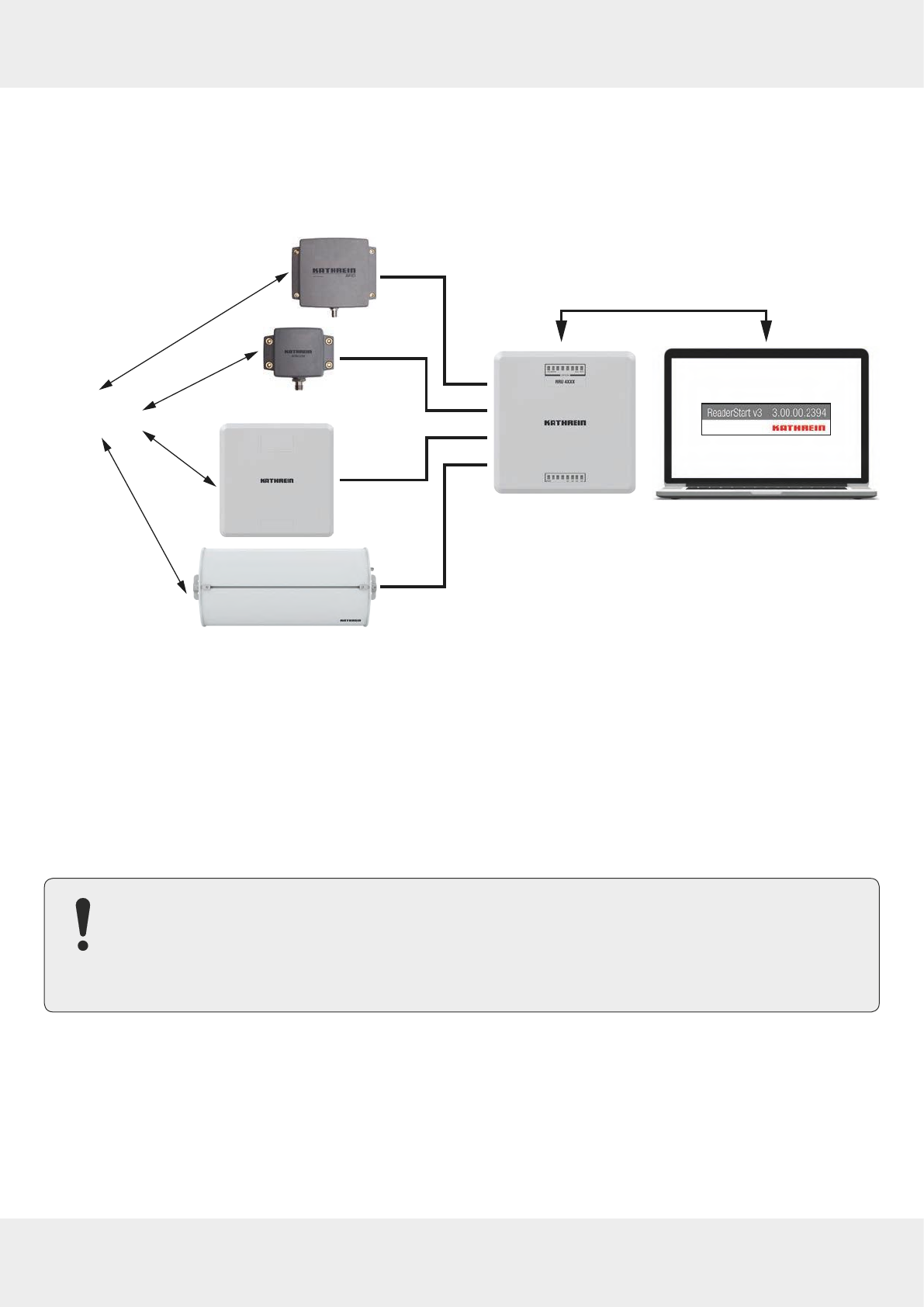
7.1 RFID System
An RFID system is comprised of the control computer of the reader, antennas, antenna connection cables and the tags.
The figure below shows the schematic structure of the system:
Ethernet
or
serial interface
RFID UHF
Gen2 Tag
Fig. 1: RFID system (example)
The tags consist of an antenna and a small chip. The chip is the true carrier of the information, the EPC (
Electronic Product
Code
) number. This number can identify products or product groups. Alternatively, the EPC can be overwritten with new
information.
To read the tag information, the reader switches on an RF carrier by means of a selected antenna, thus supplying the
tags in the RF field with energy.
To read the information from a tag, it is necessary to inventory the tags and then select a tag from the population of
tags. Upon successful completion of the inventory, the EPC number of each tag can be read and sent to the PC. It is
possible to attach additional information to the EPC, for example, the antenna which read it or the time at which it was
read.
NOTICE
The reader operates using the frequency hopping process to avoid faults and interference between readers.
Within the FCC area, this procedure is mandatory. The reader changes its transmission frequency randomly,
with equal distribution across the 52 available channels. Each channel is used for max. 400ms in an interval
of 20s.
The
ReaderStart v3
software can be used for testing and parametrising.
The communication between the
ReaderStart v3
and the reader is based on the DLL (
Dynamic Link Library
), which includes the
communication protocol, see
Communication Protocol Kathrein RFID UHF Readers
. For specific applications, the user can build its
own control software based on the reader DLL. The DLL includes all the relevant commands and functions required to
control the reader.
It is necessary for the user to create his own control software. The user-specific control software can run directly on the
reader. Therefore, a stand-alone operation without permanent network connection is possible.
15 of 112
To be able to use the complete range of the reader performance in customer applications, we recommend
using the readers ARU3500 or RRU4500. It is not possible to run any customer applications on the basic
ARU3400 and RRU4400 readers.
7.2 Kathrein RFID Antenna Interface ©KRAI
With the ©KRAI product series, Kathrein has introduced a revolutionary system. By using Kathrein ©KRAI antennas, it is
possible to increase the flexibility due to having several antenna properties at one installation point (in case of PLS and
CSB antennas) and functionality (when cascading SMSH antennas).
©KRAI consists of a digital control bus which enables connection between the RFID reader and the RFID antennas to
allow control and regulation tasks in remote antennas
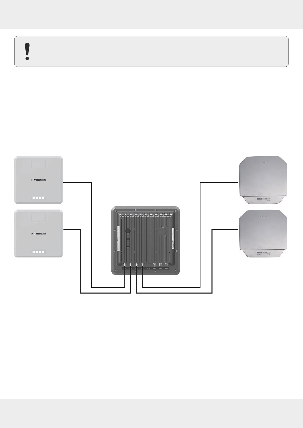
7.2.1 WIRA 70 ©KRAI Polarisation Switch Antenna (PLS)
Fig. 2: PLS antennas connected to the reader
With the ©KRAI PLS antenna, built as a WiRa 70° antenna, the polarisation can be switched statically or dynamically. The
following settings are possible in any combination:
●circular LHCP
●circular RHCP
●linear horizontal
●linear vertical.
It is possible to select the best polarisation for wide-range application and to carry out a flexible adjustment of the
antenna on site.
Furthermore, it is possible to increase the read rate via the switching circular LHCP/RHCP by up to 33%.
16 of 112
Introduction to the RIFD System
Type Order number Far-field half-power beam width Polarisation Frequency range
WIRA 70 ©KRAI ETSI 52010193 70°/70° circular 865–868 MHz
WIRA 70 ©KRAI FCC 52010194 70°/70° circular 902–928 MHz
WRA 7070 ©KRAI ETSI 52010335 70°/70° circular 865–868 MHz
WRA 7070 ©KRAI FCC 52010336 70°/70° circular 902–928 MHz
Tip PLS antennas have 4 LEDs to visualise customer applications.
The LEDs will be supplied and controlled by the RRU4xxx reader via the existing antenna cable.
Tip Note that for the internal antenna, the ARU3560 reader has all four polarisations already built in. The
ARU3560 reader cannot switch polarisation for external antennas.
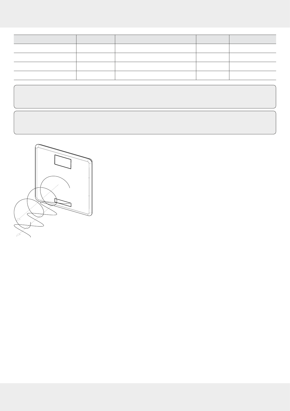
Fig. 3: Circular and linear polarisation
17 of 112
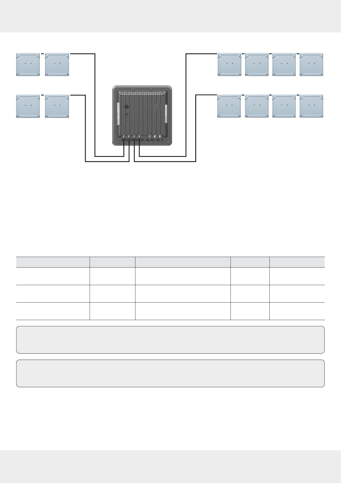
7.2.2 ©KRAI SMSH (Smart Shelf) Antenna
Fig. 4: ©KRAI smart shelf antennas connected to the reader (cascaded)
Up to 8 ©KRAI smart shelf (SMSH) antennas can be cascaded per reader port; 8 antennas x 4 ports = 32 SMSH antennas
in total.
The SMSH 3030 @KRAI slave antenna was developed for applications in the field of point of sale, smart shelf applica-
tions and Kanban solutions. The antenna is characterised by an extremely homogeneous read zone, which is emitted by
the high front-to-back ratio. Therefore, it is suitable for static detection of multiple transponders. Due to the extremely
thin design, the antenna module can be integrated into dierent applications.
The antenna is equipped with an intelligent bypass circuit that allows for cascading up to 8 SMSH antennas per reader
port. The control is done by a RRU4xxx Kathrein RFID reader. The ©KRAI control signals are transmitted via the standard
antenna cable.
Type Order number Far-field half-power beam width Polarisation Frequency range
SMSH 3030 ©KRAI ETSI
FCC antenna 52010258 60°/60° circular 865–928 MHz
SMSH high-gain 3030
©KRAI ETSI antenna 52010259 60°/60° circular 865–868 MHz
SMSH high-gain 3030
©KRAI FCC antenna 52010318 60°/60° circular 902–928 MHz
Tip Note that the ©KRAI SMSH high-gain antennas have a read range of up to 3m.
The ©KRAI SMSH standard antennas read transponders at a distance of up to 1m.
Tip Note that the SMSH high-gain antennas (order no. 52010260) and SMSH standard antennas (order no.
52010219) do not have ©KRAI and cannot be cascaded.
18 of 112
Introduction to the RIFD System
7.3 Further Reference Material
In order to configure the reader correctly and adapt it to the respective application, it is necessary to have detailed
knowledge of the EPCglobal standards of GS. This standard describes the principle of operation of the interface between
the tag and the reader.
The parameters available for the configuration of the reader are described in the
Configuration Manual for Kathrein RFID UHF
Readers
.
The reader is controlled via the Kathrein reader protocoll (KBRP), the current version of which is described in detail in the
Communication Protocol Kathrein RFID UHF Readers
.
Document Application
Communication Protocol Kathrein RFID UHF Readers
software development
Configuration Manual for Kathrein RFID UHF Readers
commissioning
Installation Manual for Kathrein Antennas
setup and installation
EPCglobal Gen2 Specification
1)
software development
Putty – SSH Client
(http://www.putty.org) software development
Make sure the version of the document matches the software version of the reader, see
https://www.kathrein-solutions.com/get-started.
1) EPCTM Radio-Frequency Identity Protocols Class-1 Generation-2 UHF RFID Version 2.0.1 at
https://www.gs1.org/epcrfid/epc-rfid-uhf-air-interface-protocol/2-0-1.

19 of 112
8 The Reader
8.1 Functional Specification
The Kathrein RFID (Radio Frequency Identification) reader of the RRU 4xxx and ARU3xxx series is a multi-protocol-ca-
pable device for reading active and passive RFID tags in the frequency range from 865 to 868 MHz for Europe and 902
to 928 MHz for the American market. Based on the latest RFID standards, such as
EPC Gen2v2
/ISO 18000-63, the Kathrein
RRU 4xxx series support all market leading transponder chip features for security, authentication and encoding. As sup-
plied, the unit can read and write tags in accordance with the
EPC Gen2v2
standard.
It is possible to load additional protocols using software updates.
The device has a maximum of four external antenna ports for connection of the transmission/reception antennas for
communication with RFID tags.
For integration into a variety of infrastructures, the device has dierent communication interfaces, depending on the
variant. The power supply is provided either by a 4-pin M12 panel connector in A coding or by PoE+ according to 802.3at
(10–57)1).
The Kathrein UHF RFID reader system RRU 4xxx is characterised by great flexibility in regard to RFID applications. One
reason for it is the wide variety of reading devices compatible to each other, which allows to select a reader from the
Kathrein product portfolio ideally suited for the respective application. Another reason for this flexibility is the wide
range of parameters for configuring the reader firmware.
8.2 Features
●basic computing module
●dual-core embedded PC
●2 Ethernet ports, 1 Ethernet port (RRU 4400 and ARU3400)
●GPIO
●©KRAI (RRU4xxx)
●PoE+
●LED visualisation
●Wi-Fi (RRU 4560 and ARU3560)
●Bluetooth (RRU 4560 and ARU3560)
●2G/3G (RRU 4570 and ARU3570)
8.3 Scope of Delivery
●RRU 4xxx reader
1) Internal supply of GPIO VCC pin is not possible with PoE+

20 of 112
The Reader
8.4 Accessories
This chapter gives an overview of the accessories available for the reader. For more information, visit our website at
https://www.kathrein-solutions.com/products/hardware/accessories or contact our sales oce at + 49 8036 90831 20.
8.4.1 Antennas
For use with UHF RFID antennas we recommend the Kathrein antenna types ULoRa, LoRa, MiRa, WiRa. These antenna
types are available for all frequency ranges and are water proof according to at least IP 65 standard.
8.4.2 Antenna Cables
Order number Type Description
52010174 R-AC 3 TNC-TNCR LL240 flex, 3 m, IP 67 ruggedised
52010175 R-AC 6 TNC-TNCR LL240 flex, 6m, IP 67 ruggedised
52010176 R-AC 10 TNC-TNCR LL240 flex,10m, IP 67 ruggedised
52010177 R-AC 15 TNC-TNCR LL240 flex,15m, IP 67 ruggedised
52010250 R-AA N-TNC LL440 flex,15m, IP 67 ruggedised
52010090 R-AC 3 SMA-TNCR RG 58, 3m
52010208 R-AC 05 SMA-SMA RG 58, 5m
8.4.3 Antenna Adapters
Order number Type Description
52010178 R-AA TNC-N(f-m) adapter TNC-N (f-m)
52010243 R-AA TNC-SMA (f-m) adapter TNC-SMA (f-m)
8.4.4 Antenna Mounting Accessories
Pole Mounting
Order number Type Description
52010005 MK-AMB-100 Outdoor wall mount/mast mount kit for WIRA 30° antennas
Wall Mounting
Order number Type Description
52010261 MK-WM-100-100 Indoor wall mount kit for WIRA 70° antennas
Wall/Pole Mounting
Order number Type Description
52010128 MK-WPM-100-100 Outdoor wall/pole mount kit for WIRA 70° antennas
52010262 MK-WPGM-100-100 Outdoor wall/pole mount kit for WIRA 40° antennas

21 of 112
8.4.5 Antenna Protective Cover
Order number Type Description
52010224 SMSH-30-30PC protective cover for SMSH
52010356 SMSH-BP-ALU aluminium backplate for SMSH
8.4.6 Reader Connecting Cables
Order number Type Description
52010358 R-CC3-10 DC RRU/ARU DC power cable, 10m
52010359 R-CC3-03 DC RRU/ARU DC power cable, 3m
52010360 R-CC3-10 ETH RRU/ARU Ethernet cable M12/RJ45, 10m
52020361 R-CC3-03 ETH RRU/ARU Ethernet cable M12/RJ45, 3m
52010362 R-CC3-10 GPIO RRU/ARU GPIO cable M12, 10m
52010363 R-CC3-03 GPIO RRU/ARU GPIO cable M12, 3m
52010373 R-BC3-10 ETH RRU/ARU Ethernet bridge cable
8.4.7 Reader AC/DC Adapters
Order number Type Description
52010364 R-RPA3 24VDC – 90W RRU/ARU AC/DC adapter 24V/90W
52010365 R-RPA 24VDC – 72W RRU/ARU AC/DC adapter 24V/72W
52010366 R-RPA 24VDC – 90W RRU/ARU AC/DC adapter 24V/90W
8.4.8 PoE+ Power Supply Unit
Order number Type Description
52020369 R-ETH-SW-100 PoE+ Ethernet switch, 4-port
52010370 R-POE-ONJ-30 PoE+ injector, 30W, 100Mbit für RRU, ARU and M-ARU
8.4.9 Reader and Antenna Wall/Pole Mounting Kit
Order number Type Description
52010351 MK-WPM3-OSS Outdoor wall/pole mount kit for RRU 4xxx, ARU 3xxx, WRA 7070 antenna
52010368 MK-PMA-OGV pole mount adapter for 52010351
8.4.10 Reader Protective Covers
Order number Type Description
52010376 PCS-G3-IP67 protective cap for RRU 4xx and ARU 3xxx, IP 67
52010367 R-RVP3-VPP-SS vandalism protective cover for RRU 4xxx and ARU 3xxx
22 of 112
Connections and Displays
9 Connections and Displays
Depending of the device variant, the reader has various connection options. The illustrations below shows an RRU 4000
standard reader with all its connection options. The following chapters provide details of the connections and the pin
assignments of plugs and sockets.
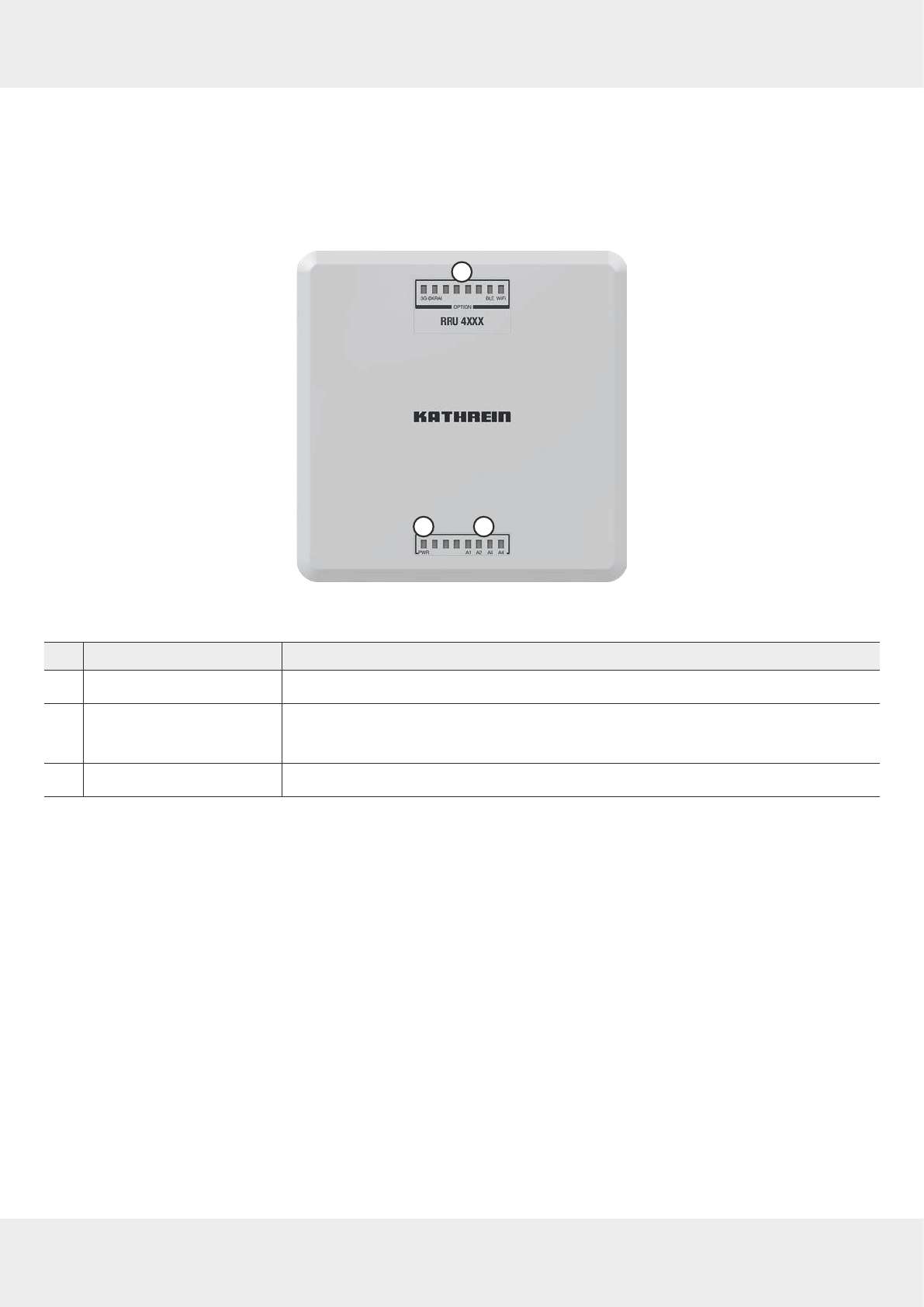
9.1 Front View
1
3
2
Fig. 5: RRU 4000 – Displays
No. Name Function
①
PWR
indicates whether the reader is on; see also
12.4 Reading the PWR LED Indications, p.36
②basic LEDs (A1-A4) indicate if an RF signal is on for antennas 1–4 (default setting)
►For other functions of the basic LEDs, see
Selecting Functions, p.79
③high-end LEDs1) see
LED, p.78
Related topics
12.4 Reading the PWR LED Indications, p.36
14.4 LED, p.78
1) Available for RRU45xx and ARU35xx
23 of 112
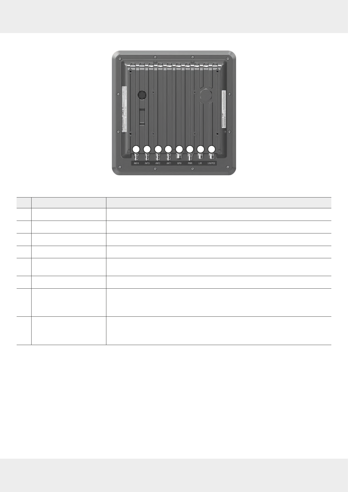
9.2 Rear View
1 2 3 4 5 6 7 8
Fig. 6: RRU 4000
No. Name Function
①
ANT 4
1) R-TNC, 50 Ohm, to connect an antenna
②
ANT 3
R-TNC, 50 Ohm, to connect an antenna
③
ANT 2
R-TNC, 50 Ohm, to connect an antenna
④
ANT 1
R-TNC, 50 Ohm, to connect an antenna
⑤
GPIO
to detect external sensors and to control external actors; see also
GPIO Functions,
p.81
⑥
PWR
to connect to a DC power supply, 10–30V
⑦
LAN
2) second Ethernet port
●to connect to a sub network
●to connect external Ethernet devices
⑧
LAN/PoE
main Ethernet port with PoE+-connectivity
●to control the reader
●to provide power supply over Ethernet
1) In the ARU3xxx readers, there are only 3 antenna ports
2) Available for RRU45xx and ARU35xx
24 of 112
Connections and Displays
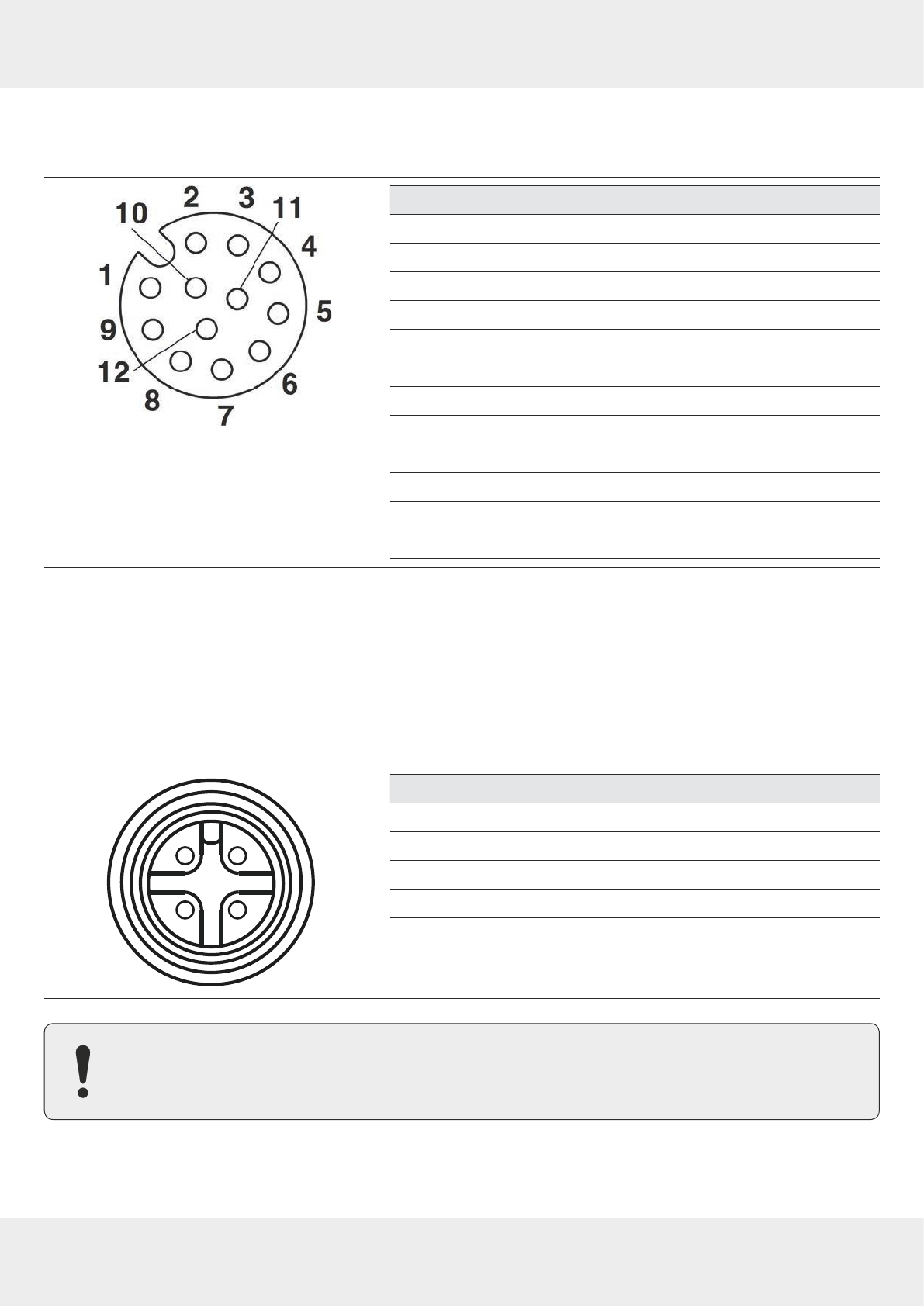
9.2.1 GPIO
M12, A-coded, 12-pin, female
Pin Allocation
1 OUT_CMN
2 OUTPUT_1
3 INPUT_3
4 INPUT_CMN
5 INPUT_1
6 GND
7 UB
8 OUTPUT_4
9 OUTPUT_3
10 OUTPUT_2
11 INPUT_2
12 INPUT_4
Related topics
14.6 GPIO Functions, p.81
9.2.2 Power Supply
The power supply is arranged as a four-pin round-pin plug with an M12 connection thread in A-coding.
M12, A-coded, 4-pin, male
2 1
3
4
Pin Allocation
1 +24 V DC
2 GND
3 GND
4 +24 V DC
Bear in mind that only power supply units with LPS (
Limited Power Source
) or NEC Class 2 power supply units
are approved for operation with the device. This means that the secondary side of the power supply unit is
limited to a power of maximum 100W.

25 of 112
9.2.3 Ethernet
NOTICE
Risk of malfunction!
If other cables then specified are used, the communication with the reader is either interrupted or
there is a malfunction.
►Only use shielded cables.
M12, X-coded, 8-pin, female
1
2
3
5
8
7
6
4
Pin Allocation
1 TX+ / PoE+1
2 TX- / PoE+1
3 RX+ / PoE+2
4 RX- / PoE+2
5 PoE+1
6 PoE+2
7 PoE+3
8 PoE+4
9.2.4 Buzzer
Furthermore, the reader is fitted with a buzzer which, in addition to the LED, indicates successful booting (1 x short) or an
error (2 x long).
26 of 112
Installing the Reader
10 Installing the Reader
When the connections are plugged in, the device satisfies the protection class IP65 (RRU and ARU).
10.1 Selecting the Installation Site
WARNING
Danger to life from electric shock or fire hazard due to incorrect voltage, insucient ventilation,
moisture, direct sunlight, heat or naked flames!
►When installing the unit in cabinets or shelves, make sure there is sucient ventilation.
►When selecting the installation location, make sure there is sucient space around the unit for
appropriate dissipation of the heat generated by the unit.
►Do not expose the unit to inadmissible heat or fire.
►Do not install the device close to the sources of heat, e.g. heating.
►Do not place anything with a naked flame on the device.
►Make sure that the maximum operating temperature from –20 to +55°C is not exceeded.
►Make sure that the support surface has a sucient load-bearing capacity/strength.
NOTICE
Risk of material damage due to the screws screwed into the reader housing too deep!
If the screws are screwed into the reader housing deeper than 10mm, the housing is no longer water
proof.
►When mounting the reader, make sure that the screws are screwed into the unit housing no deeper
than 10mm.
27 of 112
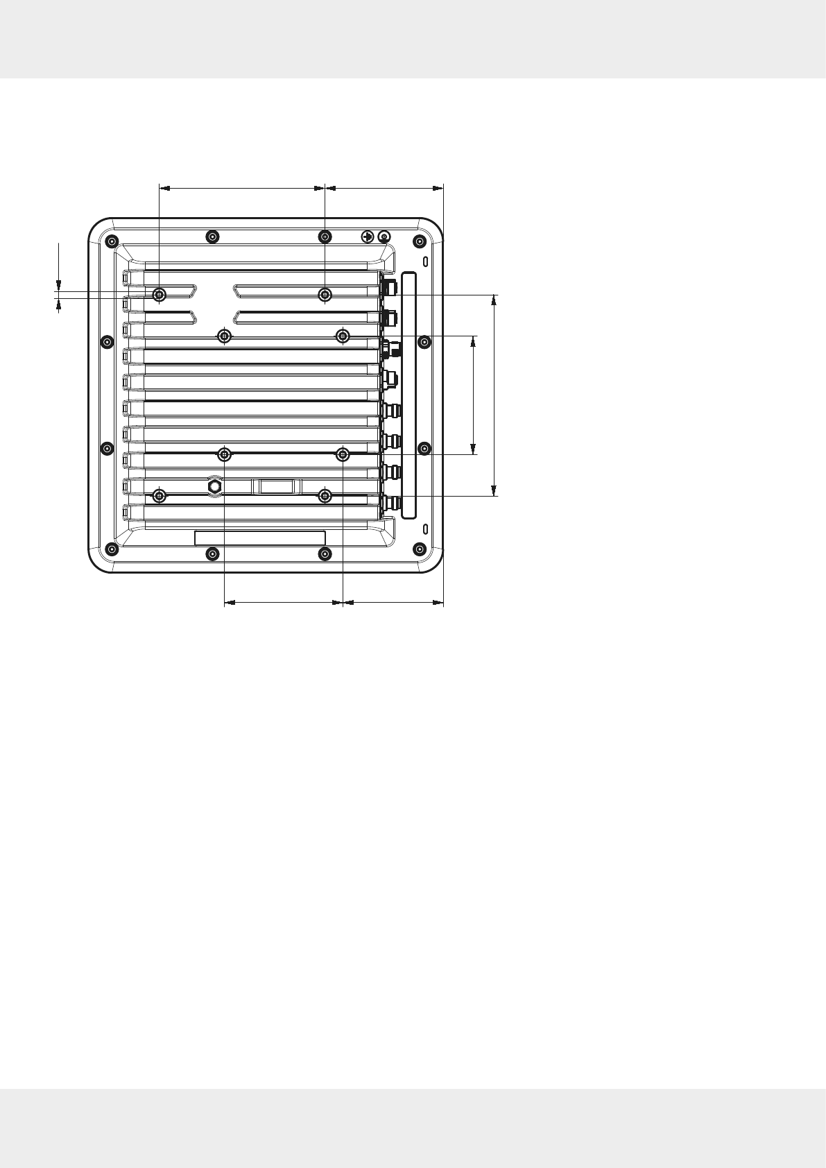
10.2 Installing the Reader
At the rear panel, the reader has threaded holes.
►See the drawing below for the dimensions of the holes.
85100
100140
100
170
M6
Fig. 7: Dimensions, rear view
28 of 112
Installing the Reader
10.2.1 Wall Mounting
Recommended for RRU4xxx, since no alignment is necessary.
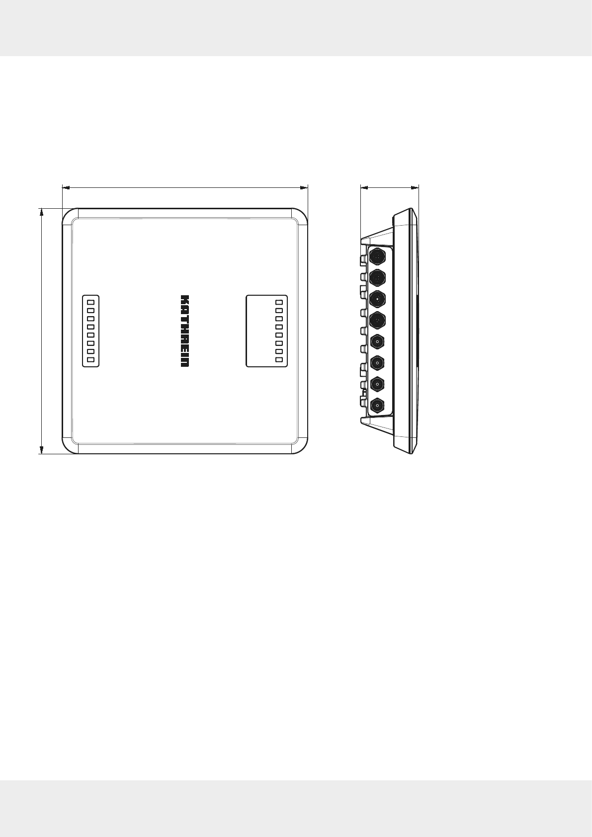
10.2.2 Wall/Pole Mounting
Recommended for ARU3xxx readers, because the alignment of the reader antenna unit is necessary.
For ease of installation, a bracket is available as an accessory to mount the reader on a wall (52010351) or a mast
(52010351 and 52010368).
300
300
71
Fig. 8: Dimensions, front and side view

29 of 112
11 Transmission Methods
11.1 UART transmission (RS232, RS422, RS485 or similar)
11.1.1 Physical Layer
A full or half-duplex connection such as RS232, RS422 or RS485 is used for the physical layer.
11.1.2 Data Link Layer
Transmission takes place in frames and blocks. A block comprises a maximum of 256 frames. A frame comprises a
maximum of 256 bytes, of which a maximum of 250 bytes can be user data. The result is a maximum block size of 64000
bytes of user data.
The data link layer is used to safeguard the data between the sender and recipient. The sender receives a response from
the recipient for each correct frame received. If the sender does not receive a response from the recipient within a time
window of 350 milliseconds after sending a frame, the frame sent is repeated until the error counter signals the cancel-
lation of the transmission.
Frame Structure
5A LL SS FF DD ... DD P1 P2
5A start code for synchronisation
LL number of bytes in the frame, not including the start code
SS status byte
FF frame number
DD user data
P1 16-bit checksum, low-byte
P2 16-bit checksum, high-byte
Start Code and Synchronisation
The start code is used to synchronise the recipient to the sender. Furthermore, the recipient synchronises to the start of
a frame when no data have been received for 100 milliseconds.
Status Byte
The status byte has the following meaning:
50 data packet
A0 response
OK
LL response
Memory error
(the recipient was unable to allocate any memory for the received data block)
A response is only 3 bytes long and is not CRC-checked.
OK 5A 02 A0
Memory error 5A 02 A1
Frame Number
The frame number shows how many more frames belong to this data block. Only the first frame in a data block can be
shorter than 256 bytes. Each additional frame must have a length of 256 bytes (length byte LL is FF).
Therefore, it is possible to calculate the block size from the first frame number, see the example below.

30 of 112
Transmission Methods
A block with 700 bytes of user data is to be transmitted. For this purpose, the block is divided into three frames:
1st frame:
5A CD 50 02
— 200 bytes of user data follow — P1 P2
2nd frame:
5A FF 50 01
— 250 bytes of user data follow — P1 P2
3rd frame:
5A FF 50 00
— 250 bytes of user data follow — P1 P2
The receiver can use the frame number of the first frame (here
02
) and its length byte to calculate the block size (block
size = frame number * 250 bytes + length byte -5) (here in the example: 2 * 250 bytes + 205 bytes - 5 bytes = 700 bytes),
and reserve an appropriate amount of memory for the data.
User Data
User data are the bytes in a frame that flow into the block transmitted.
Checksum
The checksum is calculated using the polynomial x^16 + x^12 + x^5 + 1 with a pre-initialisation of 0x0000 from the start
code to the last user data byte.
Network Layer
As the KBRP is a point-to-point protocol, there is no network layer.
Transport Layer, Session Layer, Presentation Layer,
Do not exist.
Application Layer
The application layer transmits data blocks from 1 to a maximum of 64000 bytes.
11.2 LLRP Protocol
Based on the TCP communication protocol, the Kathrein RFID reader with the Linux operating system can handle the
so-called
Low Level Reader Protocol
(LLRP).
It is a communication interface between an RFID reader and a LLRP-enabled application software standardised by
EPCglobal
(http://www.epcglobalinc.org/standards/llrp). The default port for LLRP is 5084.
The LLRP protocol is roughly divided into the following parts:
●Automatic query of the reader functions via the application software
●Configuration of the reader functions via the application software
●Triggering of read and write operations on the air interface voa the application software
●Transfer of the found tag data to the application software
To start the LLRP application, use the
AppManager
of the
ReaderStart
. In the menu, it is possible to load the LLRP protocol
engine by means of
Install App
and start it using
Start App
.
To test the Kathrein reader with the LLRP protocol, it is possible to use the open-source programming tool
Eclipse (IDE)
. By
means of the so-called
LLRP Commander
it is possible to control and operate the reader.
Eclipse (IDE)
and
LLRP Commander
are not part of the Kathrein RFID software.

31 of 112
11.3 Ethernet Transmission
A data transmission layer has been used for communication to our reader over Ethernet, just like in serial
communication.
The data transmission layer over Ethernet is a much more simple solution here since the TCP/IP protocol already has a
data security layer. As TCP/IP is a stream protocol, only the packet beginning and packet end are necessary.
There are 3 frame types in the protocol used in the Generation 3 readers.
If no data have been received for 100 milliseconds within a frame, the received part frame is dismissed. The payload (D1
to Dn) is identical to the Generation 2 payload.
11.3.1 Ethernet Transmission Generation 2 Readers
Frame Set-up
A frame looks as follows:
Start + data block + end
The start is made up of
0xAA 0xBB 0x01 0x01
, whereby the first 1 is the Datetransmit byte and the second 1 is a Stubyte. The
end is made up of
0xAA 0xCC
. If the byte
0xAA
appears in the KBRP frame, it must be doubled (
0XAA
0xAA 0xAA
).
Port
The TCP communication port is the port 4007.
Example
The frame
ASyncGetEPCs
is shown here as an example. The ID for this command is
0x0111
, which makes the frame look as
follows:
0xAA 0xBB 0x01 0x01 0x11 0x01 0xAA 0xCC
Extended Block Structure
If a data block to be transmitted exceeds 16kB, it is necessary to subdivide into several 16-kB blocks. These blocks
receive a block number, and the first block contains the total data length. It is necessary to confirm the reception of
each block by means of an answer.
First block:
Start + block number always 0 + 4-byte total data length + data block + end
All other blocks:
Start + block number + data block + end
Answer to confirm the reception:
Start + block number + end
The start consists of
0xAA 0xBB 0x0E 0x01
. The end consists of
0xAA 0xCC
. If the
0xAA
occurs in the KBRP frame, it is necessary
to double it:
0xAA
→
0xAA 0xAA
.
11.3.2 Ethernet Transmission Generation 3 Readers
Frame Set-up
Data Frame
5A 50 L1 L2 L3 L4 D1 … Dn A5
5A start code
50 code for a data frame

32 of 112
Transmission Methods
L1 – L4 number of data bytes (D1 to Dn) in the data frame (32 bit; LSB first)
D1 – D4 data bytes to be transmitted (payload)
A5 end code
Ping
5A 5F A5
5A start code
5F ping code
A5 end code
Response to Ping
5A 5F A5
5A start code
5F ping response code
A5 end code
Port
The communication takes place via the TCP port 4007 as in case of Generation 2 readers.
Example
The frame
ASyncGetEPCs
is shown here as an example. The ID for this command is
0x0111
, which makes the frame look as
follows:
0x5A 0x50 0x02 0x00 0x00 0x00 0x11 0x01 0xA5
Extended Block Structure
If a data block to be transmitted exceeds 16kB, it is necessary to subdivide into several 16-kB blocks. These blocks
receive a block number, and the first block contains the total data length. It is necessary to confirm the reception of
each block by means of an answer.
First block:
Start + block number always 0 + 4-byte total data length + data block + end
All other blocks:
Start + block number + data block + end
Answer to confirm the reception:
Start + block number + end
The start consists of
0xAA 0xBB 0x0E 0x01
. The end consists of
0xAA 0xCC
. If the
0xAA
occurs in the KBRP frame, it is necessary
to double it:
0xAA
→
0xAA 0xAA
.
33 of 112
12 Connecting the Reader
12.1 Connecting Digital Inputs and Outputs
The activation and evaluation of the inputs and outputs is carried out using the
ReaderStart V3
software, with the DLL sup-
plied or by access to the reader protocol.
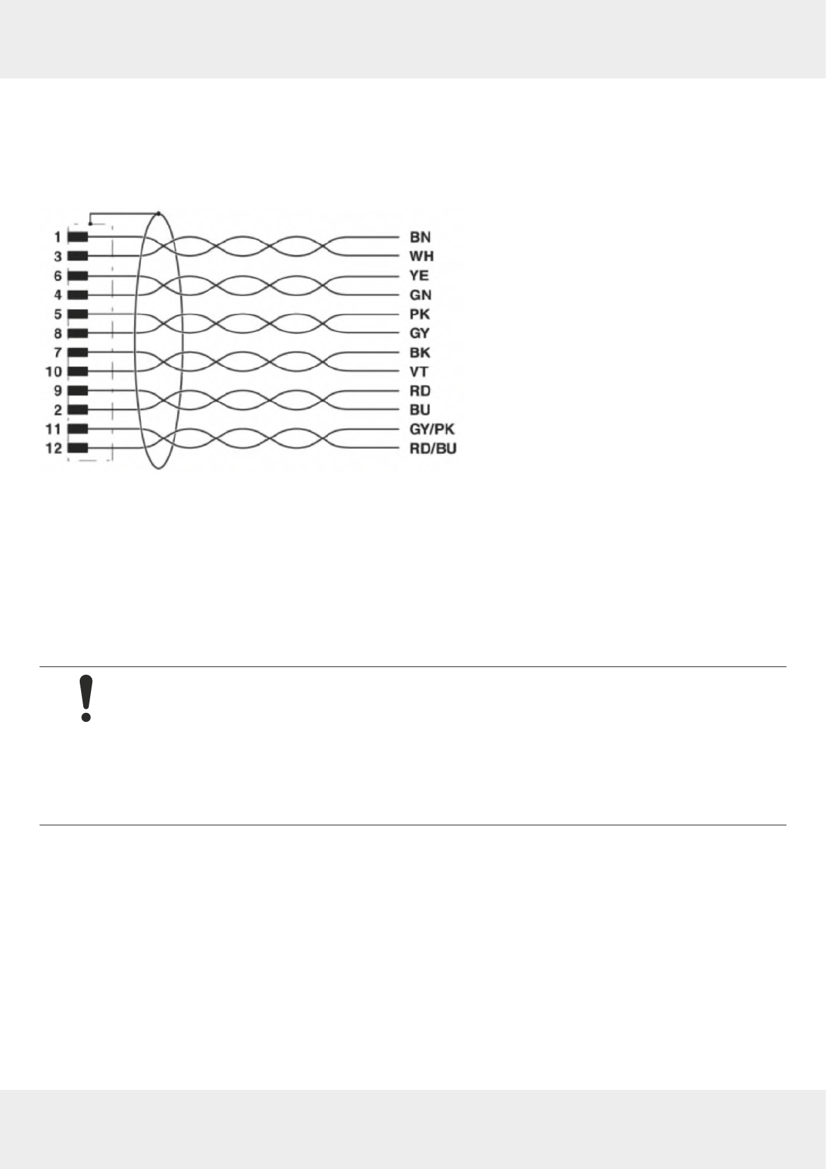
Fig. 9: Allocation of the GPIO interface cable
The digital inputs and outputs are provided via a 12-pin sockets in A-coding with M12 connection threads. The inputs
are electrically isolated from the power supply of the reader and can be operated irrespective of the polarity of the input
signal. For this reason, there is a common pin for the inputs (INP_CMN). The connection variants for the inputs are
shown below.
If the electrical isolation is not required, the power to the input can also be supplied by the reader via pin 6 and 7 (see
GPIO, p.24
).
The outputs are also DC-isolated from the power supply of the reader and have a common pin (OUT_CMN). If the elec-
trical isolation is not required, the power supply can also be taken directly from the reader.
NOTICE
Risk of malfunction!
►Note that the load per channel is limited to a maximum of 0.5 A, and the total load across all the
channels must not exceed 1.5 A. If the auxiliary voltage of the GPIO port of the reader is used, the
load can be 1.1 A as a maximum. The inputs and outputs are designed for 30VDC max.
►For further information, see the reader data sheet.
►Bear in mind that LPS or NEC Class 2 classified power supplied units can be used for the operation
of the outputs.
34 of 112
Connecting the Reader
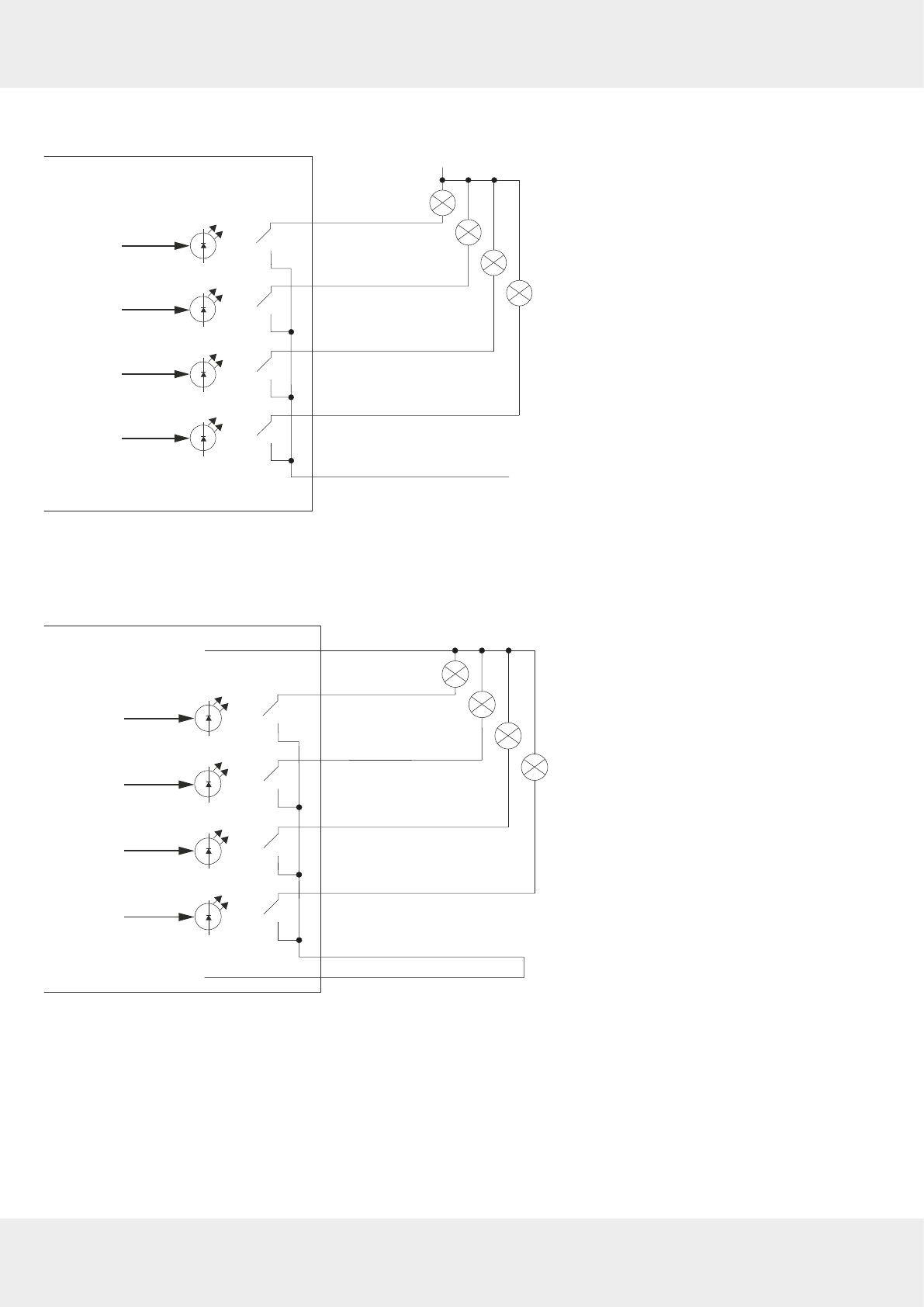
Input 1
Input 2
Input 3
Input 4
Input 1
Input 2
Input 3
Input 4
INP_CMN
+UB_extern
GND_extern
RRU/ARU xxxx
Fig. 10: DC-isolated inputs
Input 1
Input 2
Input 3
Input 4
Input 1
Input 2
Input 3
Input 4
INP_CMN
+UB
GND
RRU/ARU xxxx
Fig. 11: Inputs, not DC-isolated
35 of 112
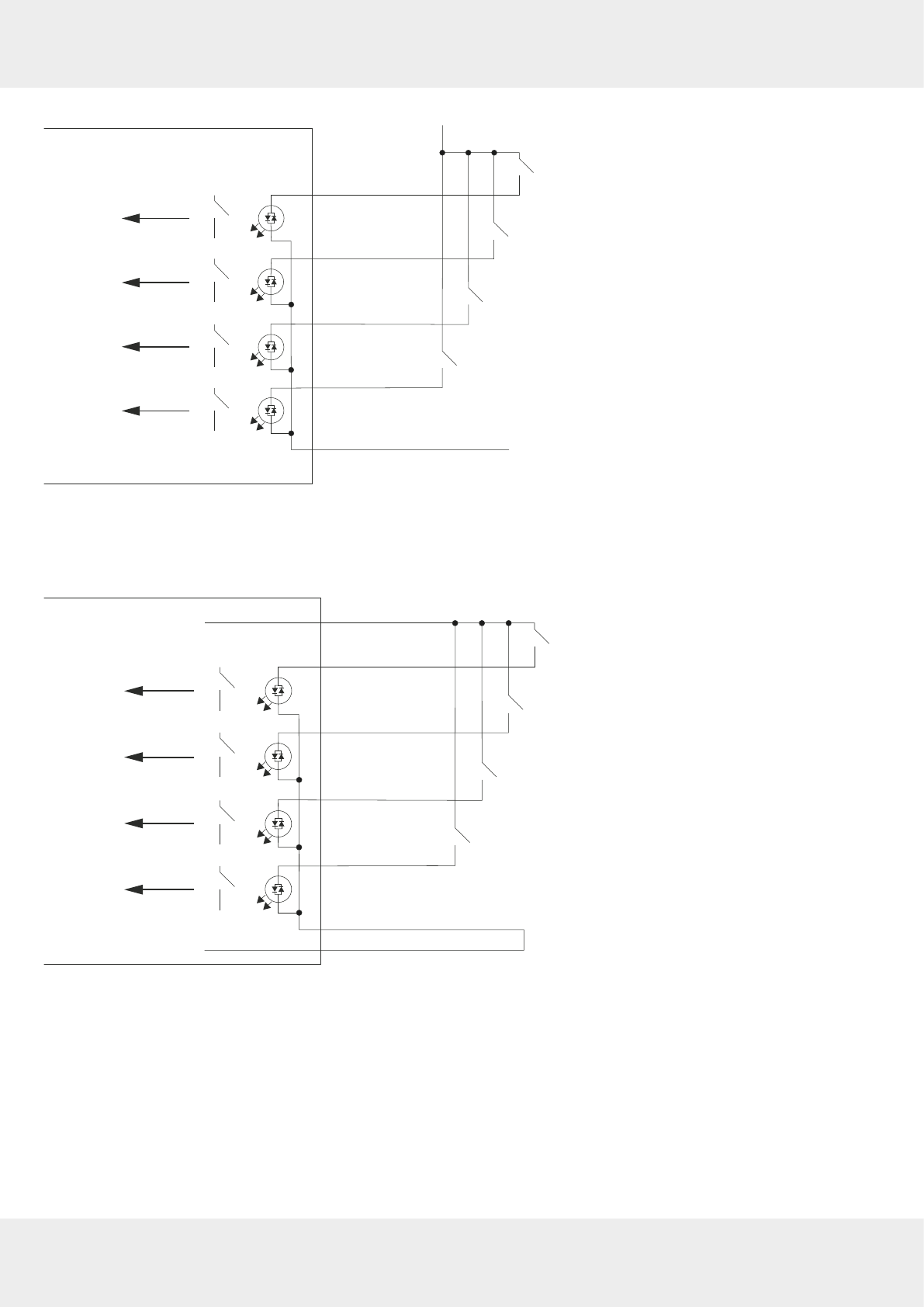
The connection examples for the outputs are shown in the next illustrations:
OUTPUT 1
OUTPUT 2
OUTPUT 3
OUTPUT 4
OUTPUT 1
OUTPUT 2
OUTPUT 3
OUTPUT 4
OUT_CMN
RRU/ARU xxxx
+UB_extern
GND_extern
Fig. 12: DC-isolated inputs
OUTPUT 1
OUTPUT 2
OUTPUT 3
OUTPUT 4
OUTPUT 1
OUTPUT 2
OUTPUT 3
OUTPUT 4
OUT_CMN
+UB
GND
RRU/ARU xxxx
Fig. 13: Outputs, not DC-isolated
36 of 112
Connecting the Reader
12.2 Connecting the Antenna
NOTICE
Risk of malfunction!
When using a cable not suitable for the impedance of 50Ohm, the performance of the reader will be
severely limited by the mismatch. If the mismatch is large, the reader may indicate a fault.
►Only use cable suitable for the impedance (50Ohm).
For the connection to the RFID antennas, the reader has four antenna connections that are of the reverse TNC design.
►Only use the cable from the accessories or equivalent cable for this connection.
12.3 Turning the Reader On and O
►Connect the reader to the power supply via a
PWR
or to a PoE source according to the 802.3at standard via
LAN /POE
input.
➯The reader is on.
12.4 Reading the PWR LED Indications
The reader has a 2-colour LED for the indication of the operating state. The table below shows the colours used and the
related operating state:
LED Action Meaning
yellow on the unit is booting
green
yellow
on
flashing approx. every 8 seconds
unit is on, normal operation with
heartbeat
yellow
green
on
flashing approx. every 8 seconds error during booting
Tip The ARU 3xxx readers have additional 4 LEDs (green/red/red/green) in the antenna cover which can be con-
trolled by means of the software.
37 of 112
13 Operating
ReaderStart
Software
The reader can be operated using the
ReaderStart
software. The software provides all the necessary functionality of the
reader for a test in a real environment. As an aid to configuration, various basic settings for application scenarios are
available.
►For the current version of the
ReaderStart
, go to
our support portal at https://support.kathrein-solutions.com/.
13.1 System Requirements
To ensure correct operation using the software on your PC/laptop, your PC/laptop should meet the following minimum
requirements:
Processor X86-compatible
Memory 512 MB RAM
Operating system Windows XP (SP3), Vista (SP1), Windows 7 or higher
Free hard disk memory for:
32-bit operating system
64-bit operating system
850 MB (including Microsoft .Net Framework 4)
2 GB (including Microsoft .Net Framework 4)
13.2 Installing the Software
Tip The setup and the
ReaderStart
software might look dierent, depending on the operating system and the soft-
ware version. The following images show the installation of the
ReaderStart V3
.
During the installation, it is checked whether the necessary requirements for the installation are met, i.e.
whether all the dependencies, such as the necessary Windows Service Packs, the .NET Framework in the
respective version together with the C++ redistributables are installed. If this is the case, the software and
the DLL for controlling the reader are installed.
1. Download the ReaderStart software at
https://support.kathrein-solutions.com.
2. Extract the downloaded zip file.
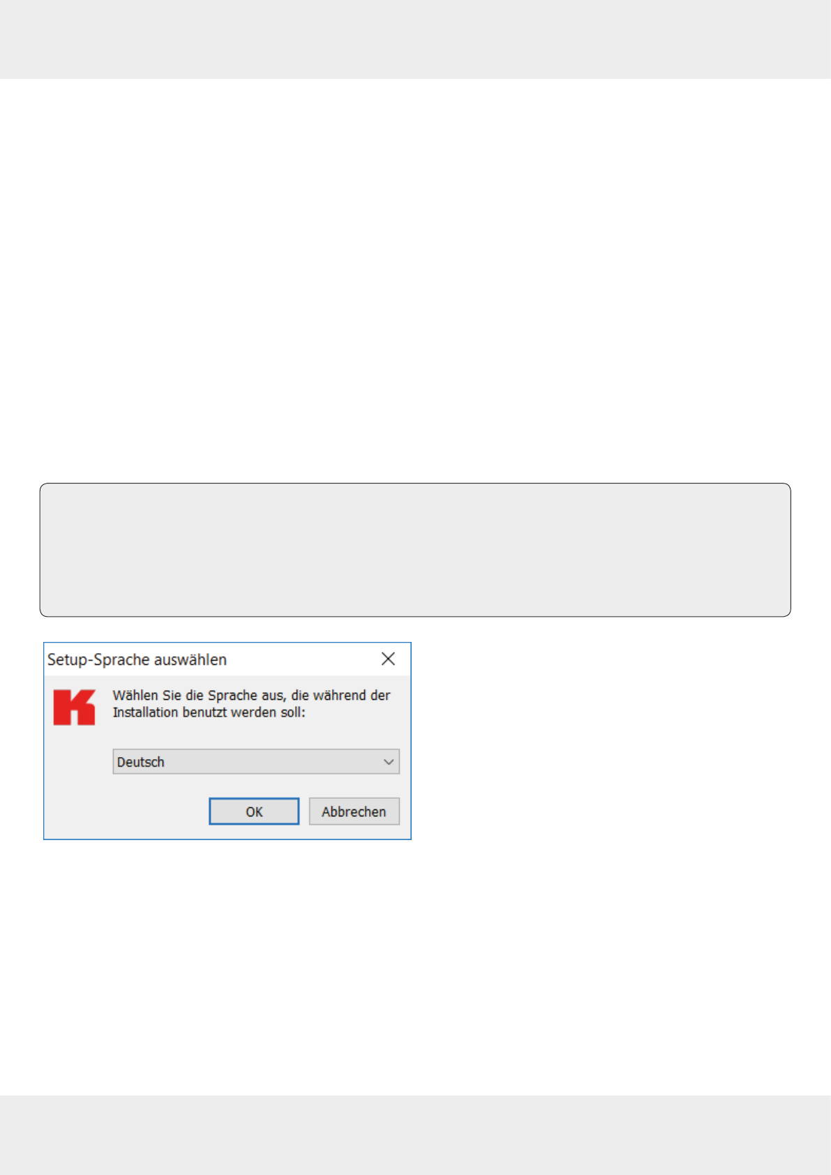
3. Double-click on the ReaderStart_v3_Setup.exe file.
➯The following screen with the option to select the
language used during the installation appears.
4. Select a language between
German
and
English
.
38 of 112
Operating ReaderStart Software
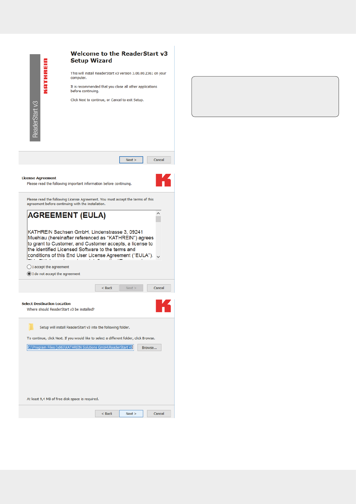
5. Click
OK
to confirm the selection.
➯The screen on the left appears. It shows additional
information on the exact version of the
ReaderStart
software.
Tip After the
ReaderStart
software has been
installed, it is possible to access this infor-
mation in the
Info
drop-down menu in the
task bar.
6. Click on
Next
to continue or
Cancel
to exit the setup.
➯The screen on the left with the licence agreement
appears.
7. Select
I accept the agreement
to continue
or
I do not accept the agreement
to exit the setup.
➯If you have accepted the license agreement in Step
7,
the window on the left appears.
8. Select the destination file for the software to be
installed.
39 of 112
9. Click
Next
.
➯The screen on the left appears. The standard set-
tings are displayed. It is possible to customise the
folder in the Windows start menu.
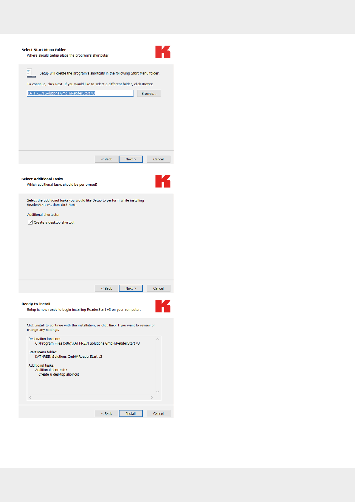
10. Click
Next
.
➯The screen on the left appears.
11. Tick the box
Create a desktop icon
if you would like to
include the icon in the Windows Quick Launch/on the
desktop. The default setting is to create no icons.
12. Click
Next
.
➯The summary of all the installation tasks appears.
13. Click
Install
to start the installation.
14. If during the installation the software requests to
restart the computer, do so.
40 of 112
Operating ReaderStart Software
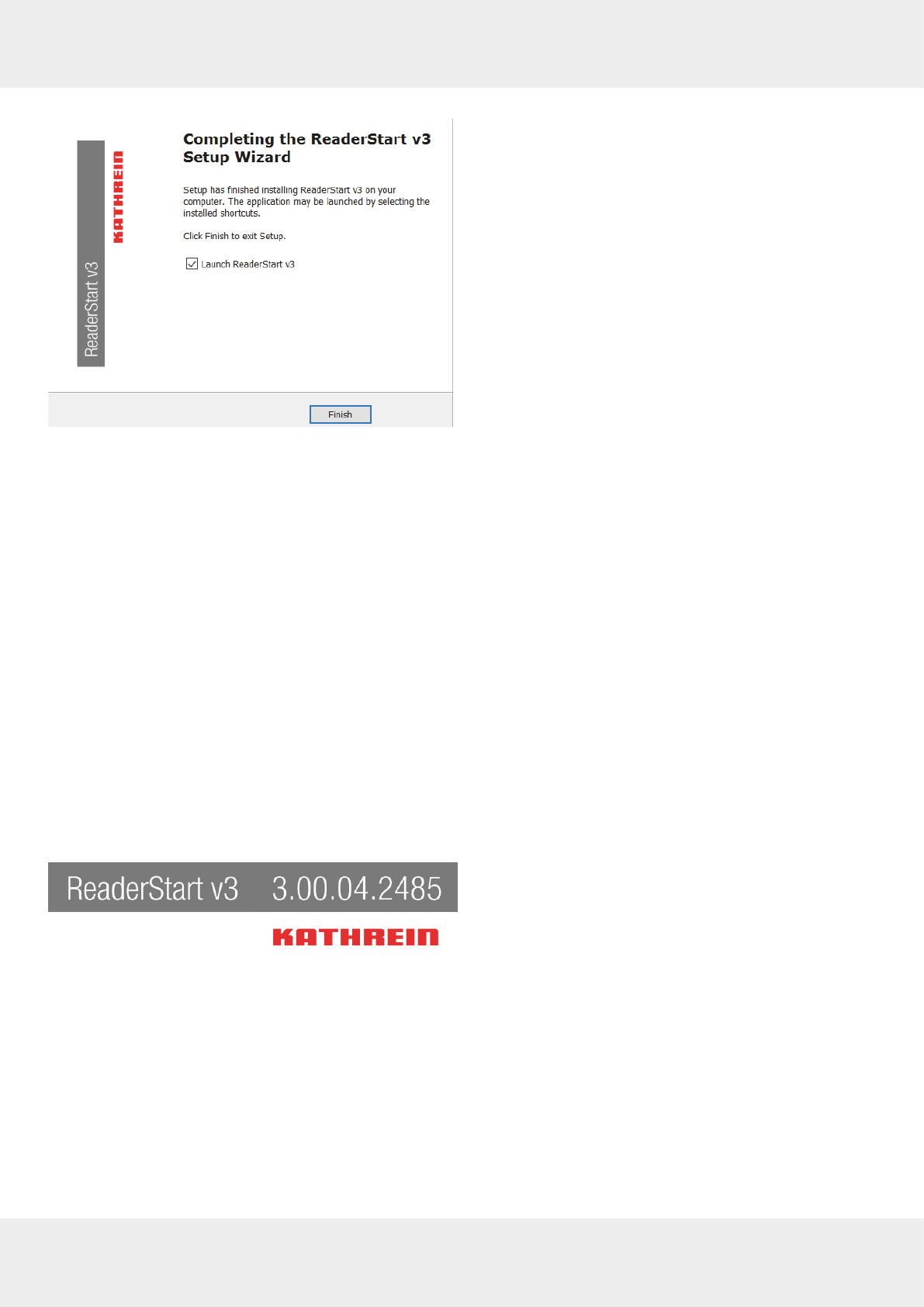
➯If the
ReaderStart
has been installed, the screen on
the left appears.
15. If you do not want to start the programme immedi-
ately, uncheck the
Launch ReaderStart v3
box. Otherwise,
the programme will automatically start once clicking
on
Finish
.
13.3 Connecting the Reader in the
ReaderStart
Software
13.3.1 Requirements
From reader firmware version 2.04, the reader in the ex-works condition has the IP address
192.168.0.1
and the network
mask
255.255.255.0
. Earlier reader firmware versions are configured for DHCP.
►To integrate the reader into a corporate network, contact your administrator so that he can allocate you a spare IP
address and assign the correct network mask.
Alternatively, it is possible to configure the reader to obtain an IP address automatically. For this service, referred to as
DHCP, it is necessary to have an appropriate DHCP server operating in the network.
►For more information, contact your network administrator.
►Make sure that the IP addresses of the control computer and the reader are in the same IP range but are not the
same. Ensure that the network mask is identical.
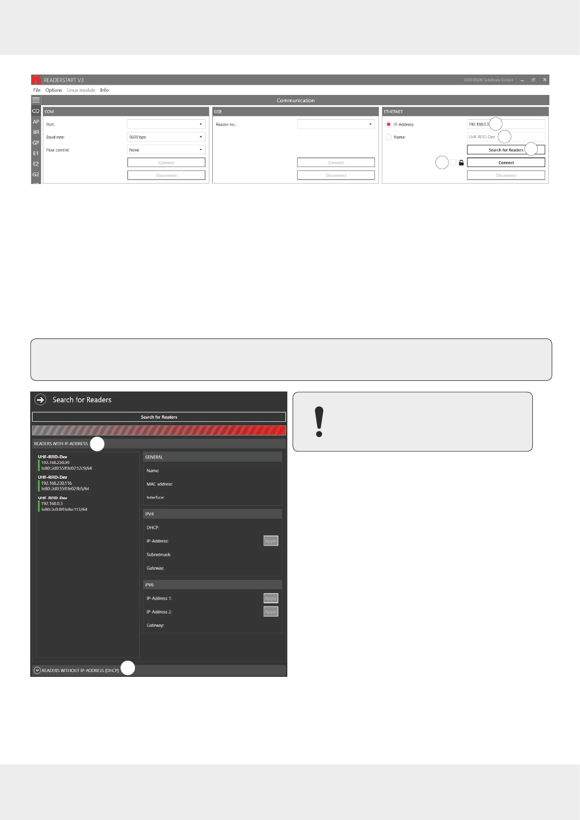
Establishing the Connection to the Reader
There are two ways to establish the connection to the reader:
●by entering the IP address to communicate directly with the reader; see
Establishing the Connection via an IP Address
or
●by using the reader's host name; see
Establishing the Connection Using a Host Name, p.41
.
►Start the programme.
➯The splash screen is shown until all the necessary
DLLs have been loaded in the background (see
figure on the left).
➯After that, the user interface appears. It consists of
the menu bar, the tabs and the status field:
41 of 112
123
4
Fig. 14: Establishing connection to the reader
Establishing the Connection via an IP Address
1. Click the
IP address
field (① in
Fig. 14
).
2. Enter the IP address.
Establishing the Connection Using a Host Name
1. Click the
Name
field (② in
Fig. 14
).
2. Enter the host name of the reader.
If you do not know the name of the reader, click
Search for Readers
.
➯The readers found in the network are shown with their names, see ⑤ in
Fig. 15.
Tip ►To allow only secure SSH connection with an encrypted transmission to the reader, check the box next
to the lock symbol (④ in
Fig. 14
); see also
Establishing a Secure Connection, p.59
.
5
6
Fig. 15: Establishing connection to the reader: search for
readers
The following steps describe establishing
the connection for readers with an IP
address.
3. In the
Ethernet
block, click
Search for Readers
(③ in
Fig. 14
).
➯The screen on the left appears.
4. Select a reader under
Readers with IP Address
(⑤ in the
figure on the left).
5. If there have been 2 or more DHCP requests sent by
the reader, the
Readers without IP Address (DHCP)
field
(⑥) is expanded. Then it is possible to assign the IP
address to the reader.
42 of 112
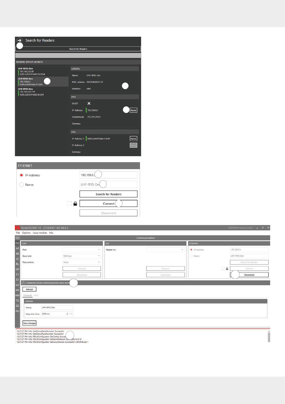
Operating ReaderStart Software
12
3
4
➯The view on the screen changes. The selected
reader has a grey background (① in the figure on
the left) and on the right (②), the properties of the
reader are shown.
6. To close this pop-up screen, click
Apply
(③) or on the
arrow (④).
1
2
3
➯The user interface returns to the main view. In the
Ethernet
block, the IP address (① in the figure on
the left) and the reader type (②) are shown.
7. Click
Connect
to connect the reader.
➯In the
Ethernet
block, the
Search for Readers
and
Con-
nect
buttons are greyed out. It is possible to dis-
connect the reader by clicking
Disconnect
(① in the
figure below). The
Communication Configuration Linux
Module
(②) and status messages from the reader/
programme are shown in the status field (③).
1
2
3
43 of 112
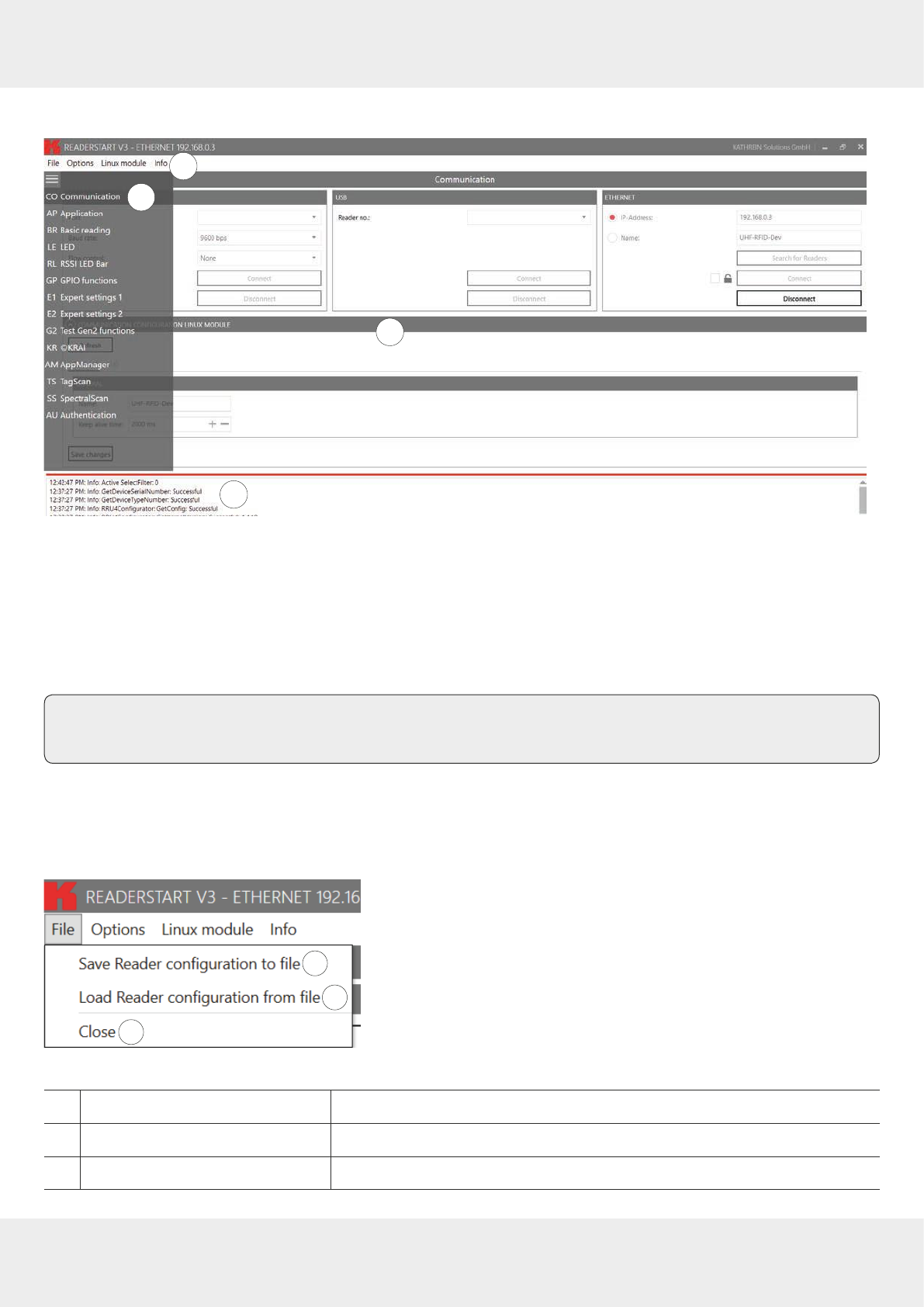
13.4 Navigating in the
ReaderStart
User Interface
1
2
3
4
Fig. 16:
ReaderStart
user interface
The user interface of the
ReaderStart
consists of the following sections:
●
menu bar
(①)
; see
Menu Bar, p.43;
●settings and controls for the reader, divided into individual functional groups and situated under dierent tabs (②)
and the contents of the tab (③), displayed in the central part of the screen; see
Operating the Reader Using the ReaderStart
Software, p.58,
●status field containing messages from the reader and the program (④); see
Status Field, p.57
Tip The contents of the tabs are considerably large and are, therefore, described in a separate chapter; see
Oper-
ating the Reader Using the ReaderStart Software, p.58
.
13.4.1 Menu Bar
By means of the menu bar, it is possible to customise the programme to the user's requirements.
File
1
2
3
Fig. 17: Menu bar: file
①
Save reader configuration to file
saves reader configuration in an XML file
②
Load reader configuration from file
loads reader configuration from a previously saved XML file
③
Close
closes
File
44 of 112
Operating ReaderStart Software
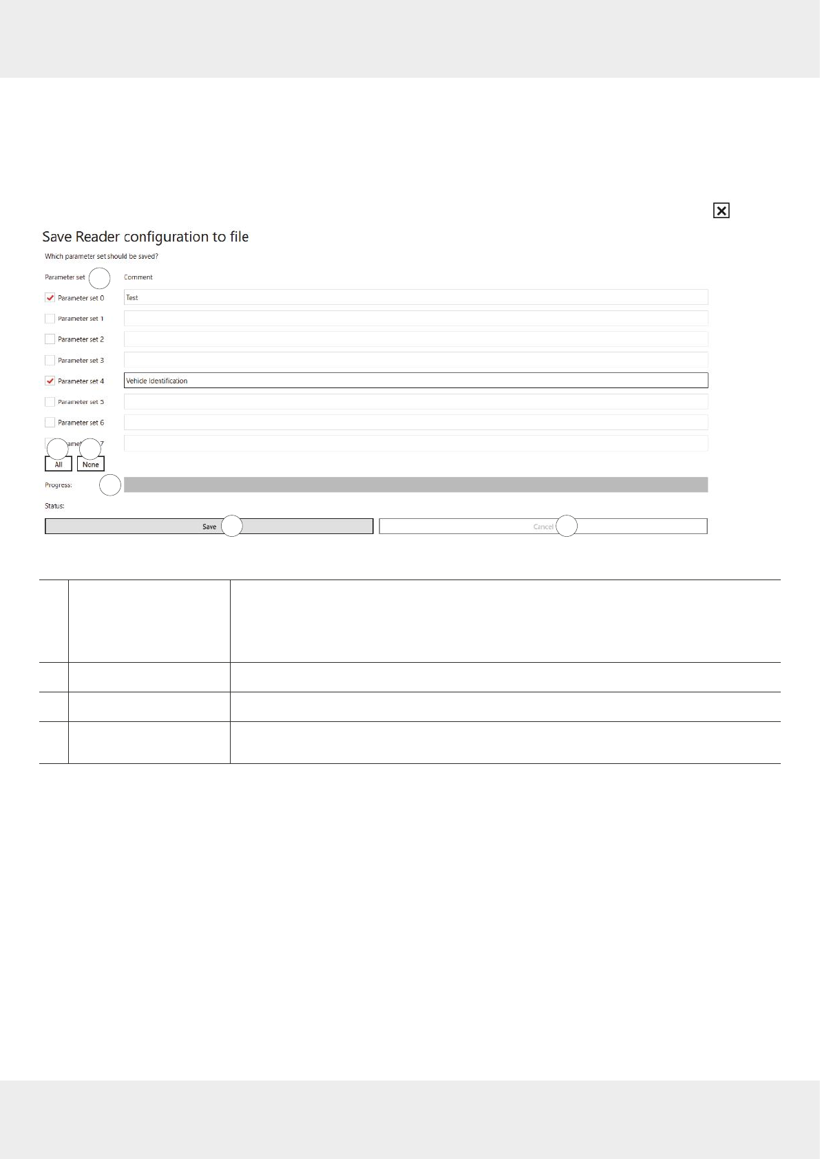
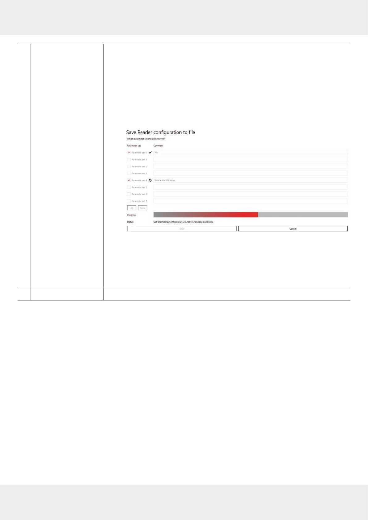
Saving Reader Configuration to File
There is a wide variety of parameters available for configuring the RF front end. It is possible to save the complete set-
ting as a parameter set in an XML file under
File
►
Save reader configuration to file
and to load it later.
►Under
FIle
, click
Save reader configuration to file.
➯The following window appears:
1
32
4
5 6
Fig. 18: File: save reader configuration to file
①
Parameter set
all available parameter sets from 0–7
►Click the check box to select or unselect the parameter set.
➯The selected parameter set is marked with a tick. If the parameter is not
selected, the check box is empty.
②
All
selects all parameter sets from 0–7
③
None
unselects all parameter sets from 0–7
④
Progress
shows the progress of the save operation by means of the progress bar; see also
Save,
p.45
45 of 112
⑤
Save
opens a pop-up window to select the directory in which the configuration file in the XML
format will be saved and the file name for it
To save reader configuration to file:
✔ The parameter sets have been selected/unselected and described.
1. Click
Save
.
➯A dialogue appears.
2. Select the file name and the directory in which the configuration file will be saved.
3. Click
OK
.
➯The progress bar (④) shows the progress of the save operation:
➯After the file has been saved, a pop-up message
Save reader configuration to file
Saving done
appears.
4. Click
OK
to close the pop-up message.
➯The software returns to the view shown in
Fig. 18,p.44
.
5. Click the
X
at the top right-hand corner or press
Escape
on your PC keyboard to leave
the dialogue.
⑥
Cancel
cancels the saving process
46 of 112
Operating ReaderStart Software
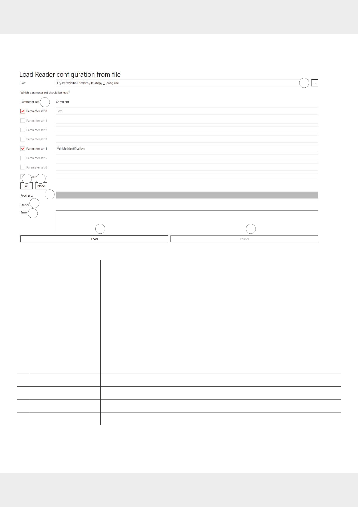
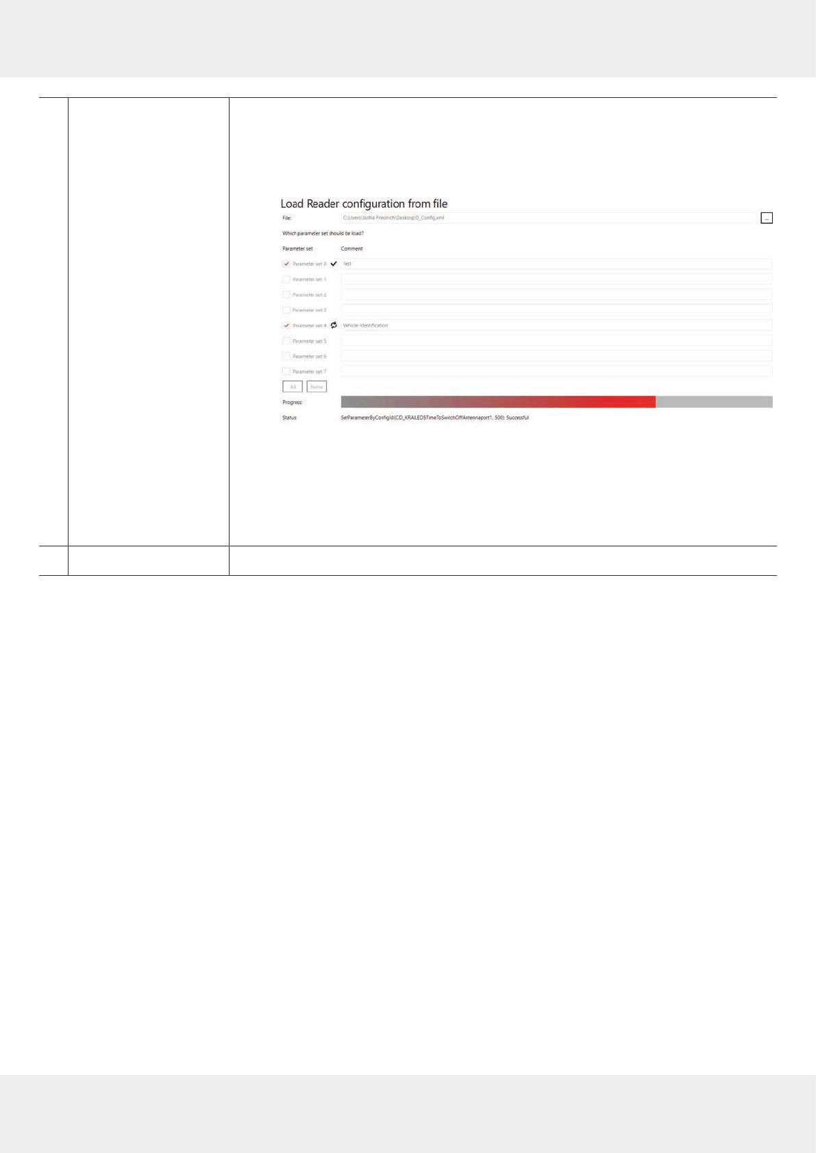
Loading Reader Configuration from File
►Under
FIle
, click
Load reader configuration from file.
➯The following window appears:
1
3
2
4
8 9
5
6
7
Fig. 19: File: load reader configuration from file
①
File
opens a dialogue to select the configuration file
To load reader configuration to file:
1. Click
File
(④ in
Fig. 19
).
➯A dialogue appears.
2. Select the directory and the configuration file from which the parameter sets will be
loaded.
3. Click
Open
.
➯The parameter sets saved in the configuration file are loaded and are marked
with a red tick.
➯The progress bar (⑤) shows the progress of the save operation.
②
Parameter set
see
Parameter set, p.44
③
All
see
All, p.44
④
None
see
None, p.44
⑤
Progress
shows the progress of the load operation by means of the progress bar
⑥
Status
shows the status of the SetParameterByConfigID parameter
⑦
Error
shows errors in the SetParameterByConfigID parameter
47 of 112
⑧
Load
loads the selected parameter sets to the reader
✔ The parameter sets to be loaded have been selected/unselected.
1. Click
Load
.
➯ The progress bar (④) shows the progress of the save operation:
➯After the configuration has been loaded, a pop-up message
Load reader configura-
tion from file Loading done
appears.
2. Click
OK
to close the pop-up message.
➯The software returns to the view shown in
Fig. 19,p.46
.
3. Click the
X
at the top right-hand corner or press
Escape
on your PC keyboard to leave
the dialogue.
⑨
Cancel
cancels the loading process
Close
►Click
Close
to close the
ReaderStart
.

48 of 112
Operating ReaderStart Software
Options
1
2
3
4
5
6
7
8
Fig. 20: Options
①
Language select
selects the user interface language between
English
/
German
/
Spanish
/
French
1. Click
Language select
(① in
Fig. 20
).
➯The four languages are shown. The language applied in the user interface is
marked with a tick.
2. Click on the desired language.
➯A pop-up message appears:
Question. Please restart the programme to apply changes.
Restart now?
3. Click
Yes
to restart the programme and change the language or
Click
No
to cancel the changes.
➯If you have pressed
Yes
, the programme restarts and the language of the user
interface has been changed.
②
Reset layout
resets the sequence of the tabs to default settings and reduces the size of the pro-
gramme to the window size
③
Change path to log file
opens a dialogue to create a new folder/select a new directory to save logs
④
Show "No Tag" as warning
activates or deactivates the warning (yellow) in the status field if no tag has been
detected in the antenna field; see
Status Field, p.57
If this parameter is not checked, the absence of the tag is shown as error (red) in the
status field; see
Status Field, p.57
⑤
Auto tag read on tab change
activates or deactivates reading tags after the tab change
⑥
Firmware update
updates the reader firmware; see
Updating Firmware, p.49
⑦
Date and time settings
sets date, time and time zone on the reader; see
Changing Date and Time Settings, p.50
⑧
Load factory defaults
loads factory default settings onto the reader; see
Loading Factory Default Settings, p.51

49 of 112
Updating Firmware
1. Click
Firmware update
.
➯A dialogue appears. ① shows the current firmware version.
1
32
5 6 7
4
2. Click on the box at
Path to update file
(②).
➯A dialogue opens to select the file with the current firmware.
3. Having selected the update file, click
Update
(⑤).
➯The reader firmware is being updated. The update progress is shown by means of the progress bar (③). The
status (④) shows what the software is currently performing, e.g.
Preparing
,
Transferring data: 2588672 of 211353360
bytes
,
Flashing
.
Click
Cancel
(⑥) to stop the update process.
4. After the update has been completed, click
Reboot
(⑦) to restart the reader.
50 of 112
Operating ReaderStart Software
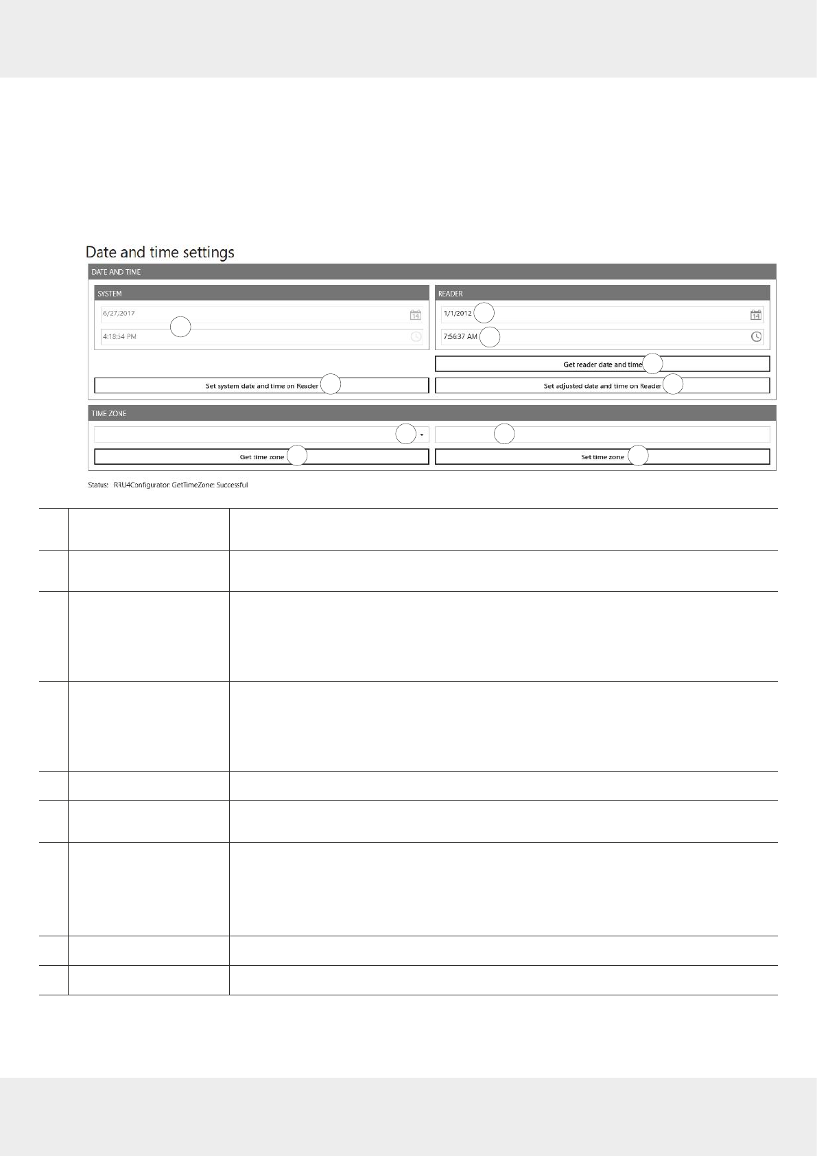
Changing Date and Time Settings
The reader has an integral clock which can deliver the time stamp for a tag operation. It is possible to set the clock
using
Date and time settings
under
Options
in the menu bar. When this menu item is opened, it automatically reads the cur-
rent date and time from the reader and compares this with the date and time from the host computer. The date and time
of the host computer can now be loaded to the reader by pressing the
Set system date and time on Reader
button.
1. Click
Date and time settings
.
➯A dialogue appears. It automatically reads the current date and time from the reader (③ and ④) and compares
them with the date and time from the host computer (①).
13
2
4
56
9 10
7 8
①Date and time of the
ReaderStart
software shows the date and time of the
ReaderStart
software; cannot be changed
②
Set system date and time on
reader
loads the system date and time shown in ① onto the reader
③Current date of the
reader
shows the current date of the reader
1. To change the reader's date, either type the new date into the line or click on the
calender symbol in the line and select the date.
2. Click
Set adjusted date and time on reader
.
④Current time of the
reader
shows the current date of the reader
1. To change the reader's time, either type the new time into the line or click on the
clock symbol in the line and select the time.
2. Click
Set adjusted date and time on reader
.
⑤
Get reader date and time
reads the current date and time from the reader and displays them in ③ and ④
⑥
Set adjusted date and time
on reader
sets the adjusted date and time on reader; see ③ and ④
⑦Time zone selection
selects the time zone
1. Click on the drop-down menu symbol (⑦).
2. Select the continent and the city.
➯ The time zone is displayed at (⑧).
⑧
Get time zone
reads the time zone currently set in the system
⑨
Set time zone
sets the time zone selected at ⑦
51 of 112
Loading Factory Default Settings
1. Click
Load factory defaults
.
➯A pop-up message appears:
Are you sure to load factory defaults?
2. Click
Yes
to load factory default settings or
Click
No
to cancel the operation.
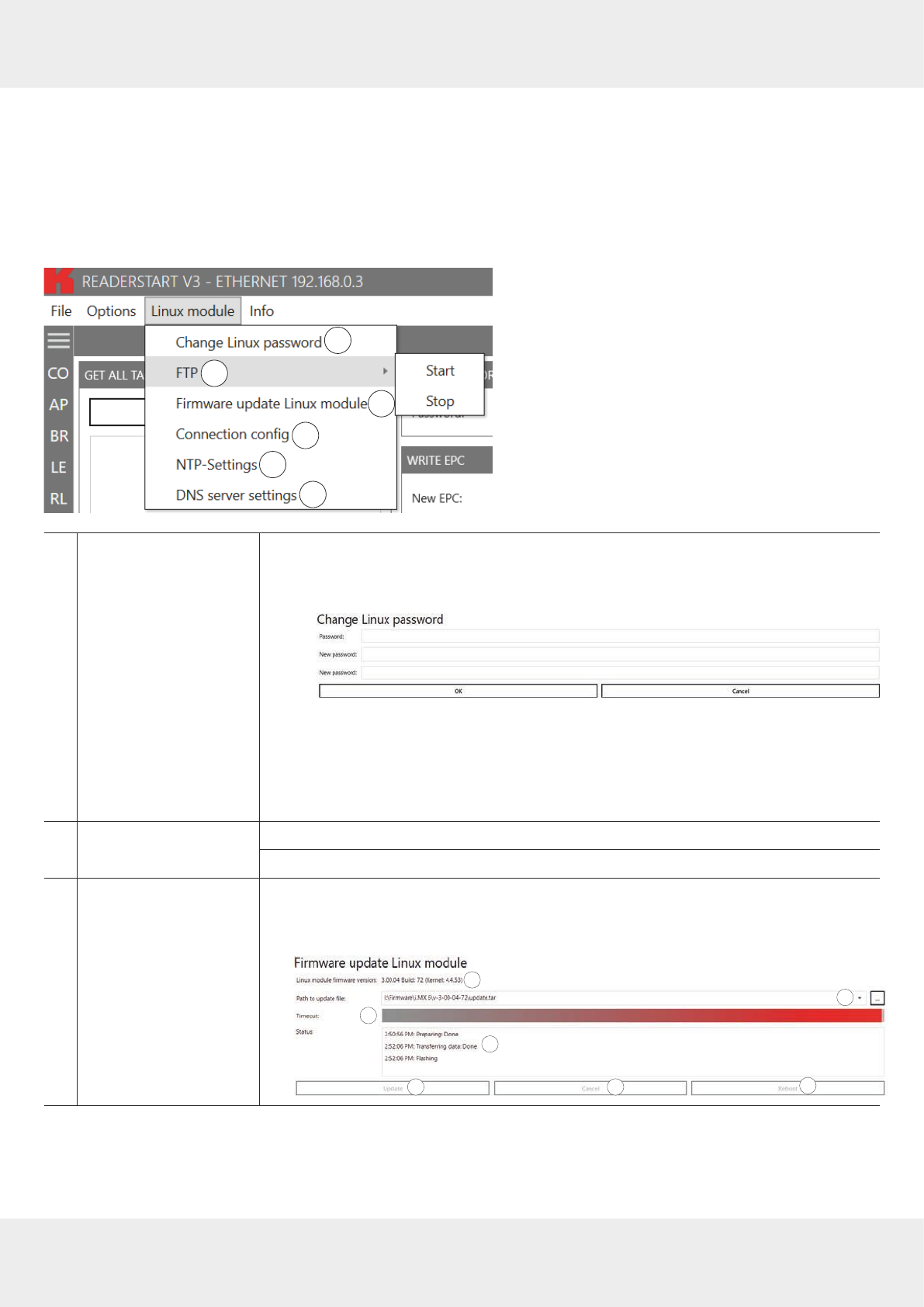
Linux Module
1
23
4
56
①
Change Linux password
changes the Linux password
1. To change the password, click
Change Linux password
.
➯The following pop-up window appears:
2. Type in the old password.
3. Type in the new password.
4. Confirm the new password.
5. Click
OK
to change the password or
Click
Cancel
to stop the process.
②
FTP Start
starts FTP server
Stop
stops FTP server
③
Firmware update Linux
module
updates Linux module firmware
►Proceed as described in
Updating Firmware, p.49
. Make sure to select the file to
update the Linux module firmware at
Path to update file
(②).
1
32
5 6 7
4
52 of 112
Operating ReaderStart Software
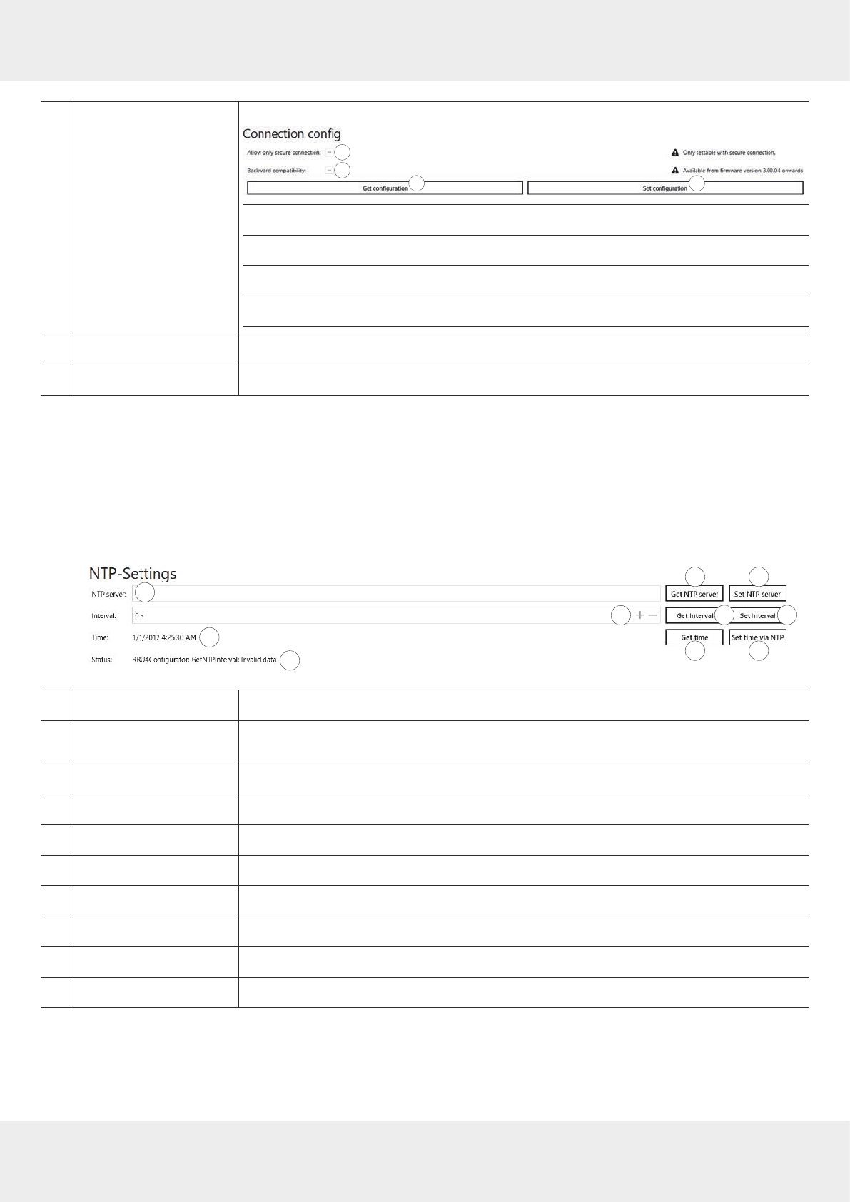
④
Connection config
configures the secure connection and the backward compatibility
1
3
24
① ►Check
Allow only secure connection
so that all connections are secure.
②activates or deactivates compatibility to Generation 2 KBRP
③reads the current secure connection and backward compatibility configuration
④sets the secure connection and backward compatibility configuration
⑤
NTP settings
enters a preferred NTP1) server; see
Changing NTP Settings, p.52
⑥
DNS server settings
changes DNS server settings; see
Changing DNS Server Settings, p.53
Changing NTP Settings
To simplify the time setting, it is possible to enter a preferred NTP server. This way, in a defined interval, the reader
retrieves the information from the NTP server and gets the time from the network, thus setting the internal time settings
of the reader.
►Click
NTP settings
(②).
➯The following dialogue opens.
1
32
4
5 6
7 8
9 10
①
NTP server
enters an NTP server address, e.g. 0.pool.ntp.org
②
Interval
sets the interval in the range 0–4204967295 s to synchronise the time with the NTP
server
③
Time
shows the current date and time of the reader
④
Status
shows the status of the last performed operation in the
NTP setting
s dialogue
⑤
Get NTP server
reads the NTP server settings currently set in the system
⑥
Set NTP server
sets the NTP server selected at ①
⑦
Get interval
reads the interval currently set in the system
⑧
Set interval
sets the interval selected at ②
⑨
Get time
gets the current time of the reader
⑩
Set time via NTP
manually synchronises the time with the NTP server
1)
Network Time Protocol
53 of 112
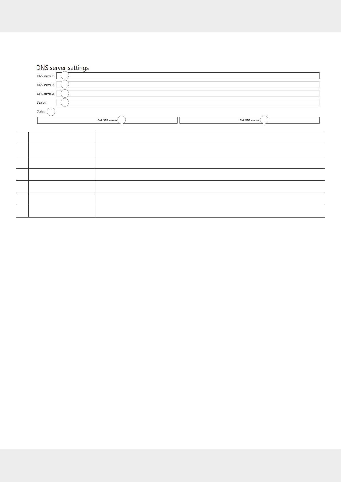
Changing DNS Server Settings
►Click
DNS server settings
(②).
➯The following dialogue opens.
1
3
2
4
5
6 7
①
DNS server 1
enters the DNS server address
②
DNS server 2
enters the DNS server address
③
DNS server 3
enters the DNS server address
④
Search
contains the local domain name
⑤
Status
shows the status of the last performed operation in the
DNS server setting
s dialogue
⑥
Get DNS server
reads the DNS server settings currently set in the system
⑦
Set DNS server
sets the DNS server
54 of 112
Operating ReaderStart Software
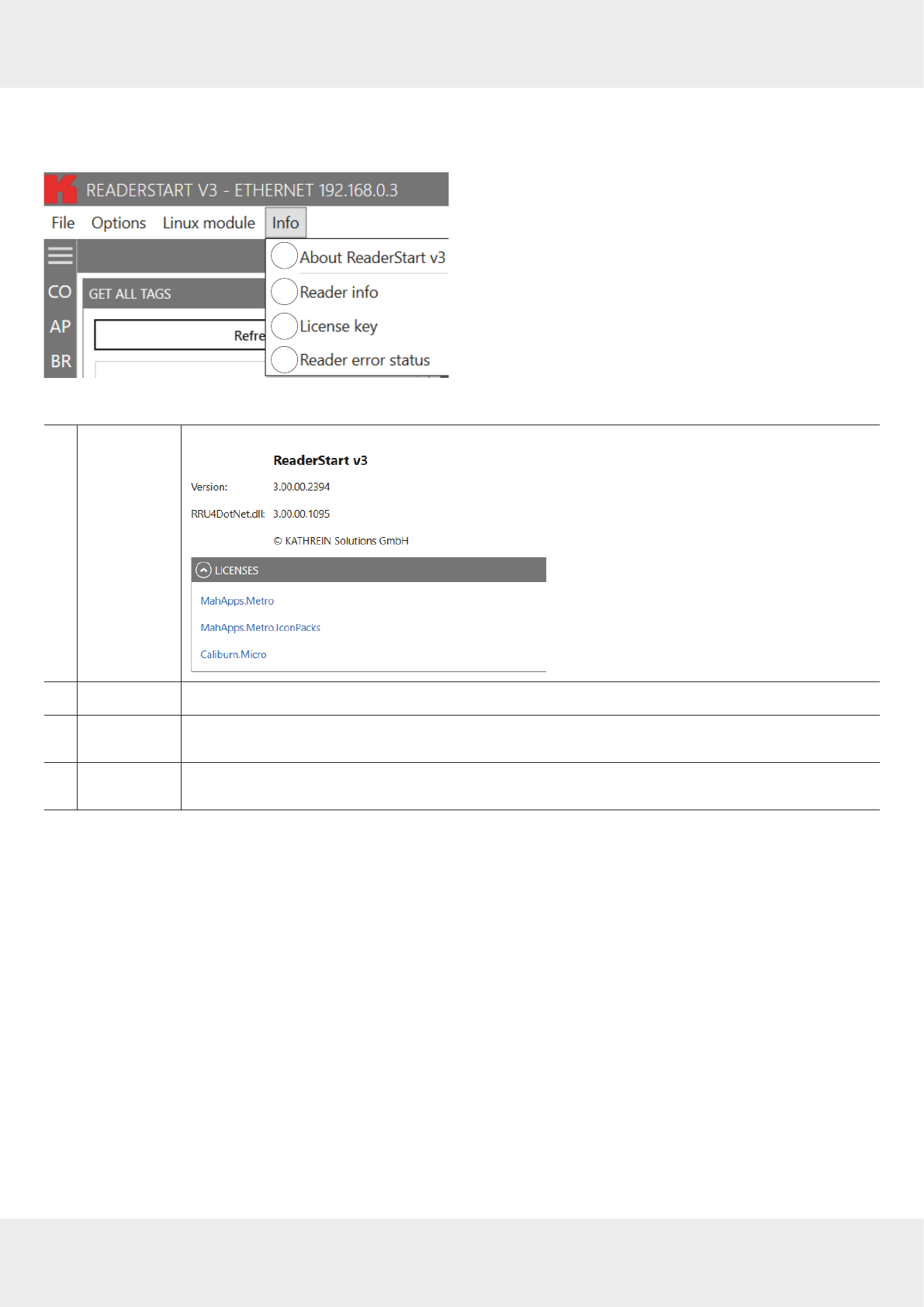
Info
This menu item provides information about the
ReaderStart
software and the reader.
1
3
2
4
Fig. 21: Info
①
About Reader-
Start v3
shows the version number of the software and links to the licenses
②
Reader info
shows information about the reader; see
Showing Reader Information, p.55
③
License key
automatically reader the license key and show various factory-set reader parameters; see
Showing
License Key Information, p.56
④
Reader error
status
reads the error status of the reader and shows all errors that are outstanding in the status field
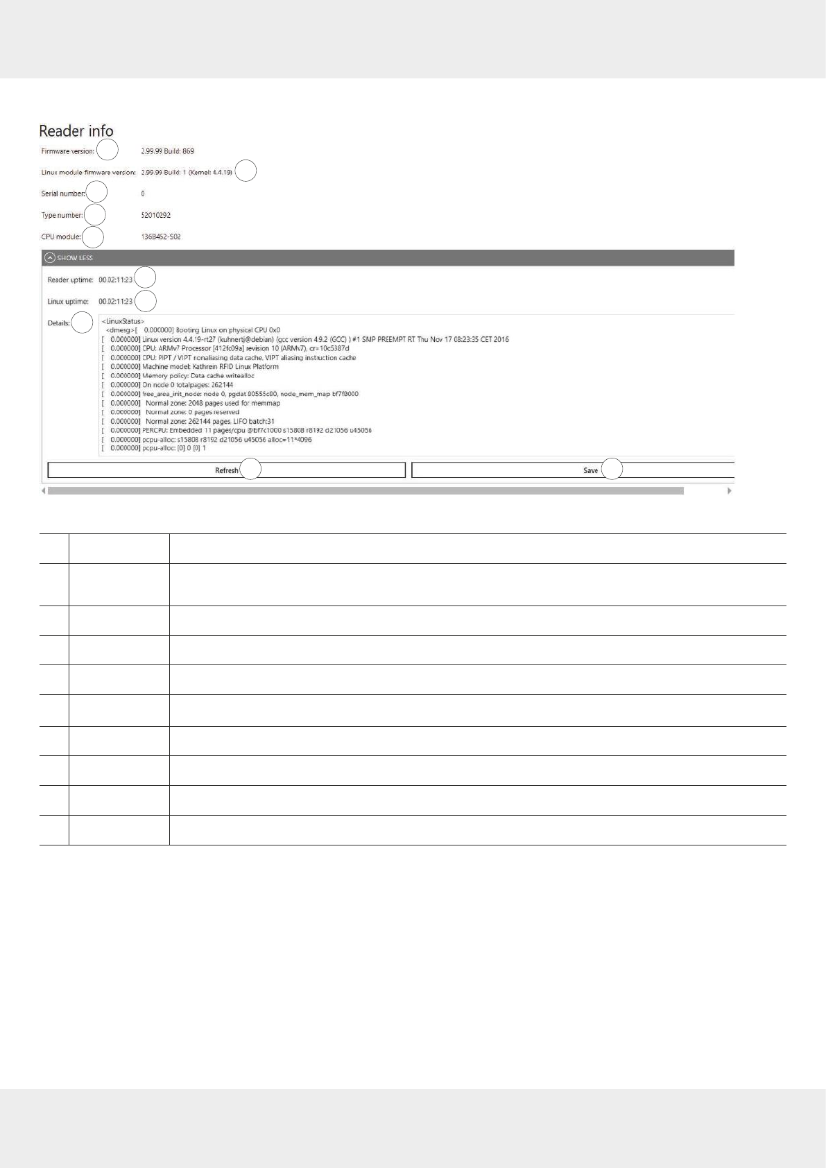
55 of 112
Showing Reader Information
1
32
4
5
6
7
8
9 10
Fig. 22: Info: reader info
①
Firmware version
shows reader firmware version
②
Linux module
firmware version
shows Linux module firmware version
③
Serial number
shows the reader's serial number
④
Type number
shows the reader's type number
⑤
CPU module
shows the CPU module number
⑥
Reader uptime
shows time during which the reader has been running
⑦
Linux uptime
shows time during which the Linux module has been running
⑤
Details
shows details about the reader
⑨
Refresh
updates the reader and Linux uptime
⑩
Save
saves the reader info in an XML file
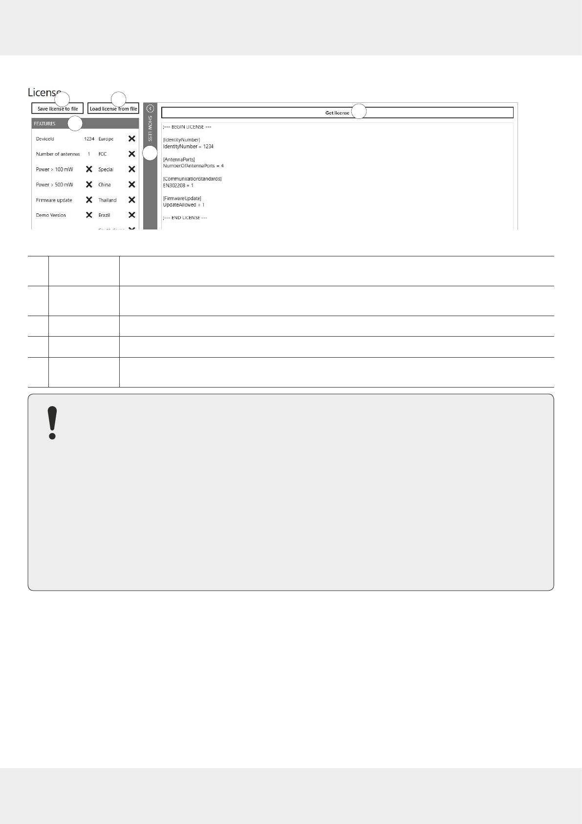
56 of 112
Operating ReaderStart Software
Showing License Key Information
13
2
4
5
Fig. 23: Info: license key
①
Save license to
file
saves the license key in a license file
②
Load license
from file
loads a license key from a license file
③
Get license
shows the current license key details
④
Features
shows factory-set parameters of the reader
⑤
Show less/Show
more
shows/hides the information shown in the right part of the screen under
Get license
In certain cases, it is necessary to send the license key to KATHREIN Solutions GmbH.
1. To do so, click
Save license to file
(① in
Fig. 23
).
2. Select the file name and the destination directory.
3. Send the file to KATHREIN Solutions GmbH.
To send the file to KATHREIN Solutions GmbH:
1. Go to the support portal of the KATHREIN Solutions GmbH at https://support.kathrein-solutions.com/.
2. If you do not have an account yet, create an account.
3. After the successful registration, click
Ticket Tracking
.
4. Click
Add Ticket
.
➯A new mask appears in which you can describe your question and attach files.
5. Attach the file with the license key by clicking
Browse
.
6. Click
Save
to send the file to the KATHREIN Solutions GmbH support team.
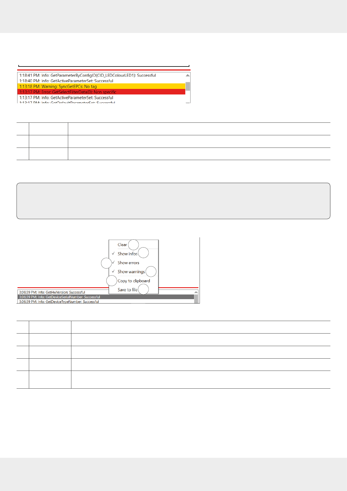
57 of 112
13.4.2 Status Field
3 message types are defined, see the example below:
Fig. 24: Status field
①
Info
shows which action has been recently performed
②
Warning
indicates possible problems in the structure and configuration
③
Error
indicates that the required action could not be executed
Every status message has a time stamp next to it. The status messages are arranged such that the most current one is
always at the top of the list.
Tip ►To expand the status field section and see more status messages, click on the boundary line between
the sections (red line in
Fig. 24
) and drag it upwards.
►To minimise the status field section, drag the line downwards.
The status field has a context menu which allows to deactivate warnings, information and errors in the status field. It is
also possible to delete status messages.
12
34
56
Fig. 25: Status field context menu
①
Clear
deletes all status messages
②
Show infos
shows/hides infos
③
Show errors
shows/hides errors
④
Show warnings
shows/hides warnings
⑤
Copy to
clipboard
copies the status field entries to the Windows clipboard
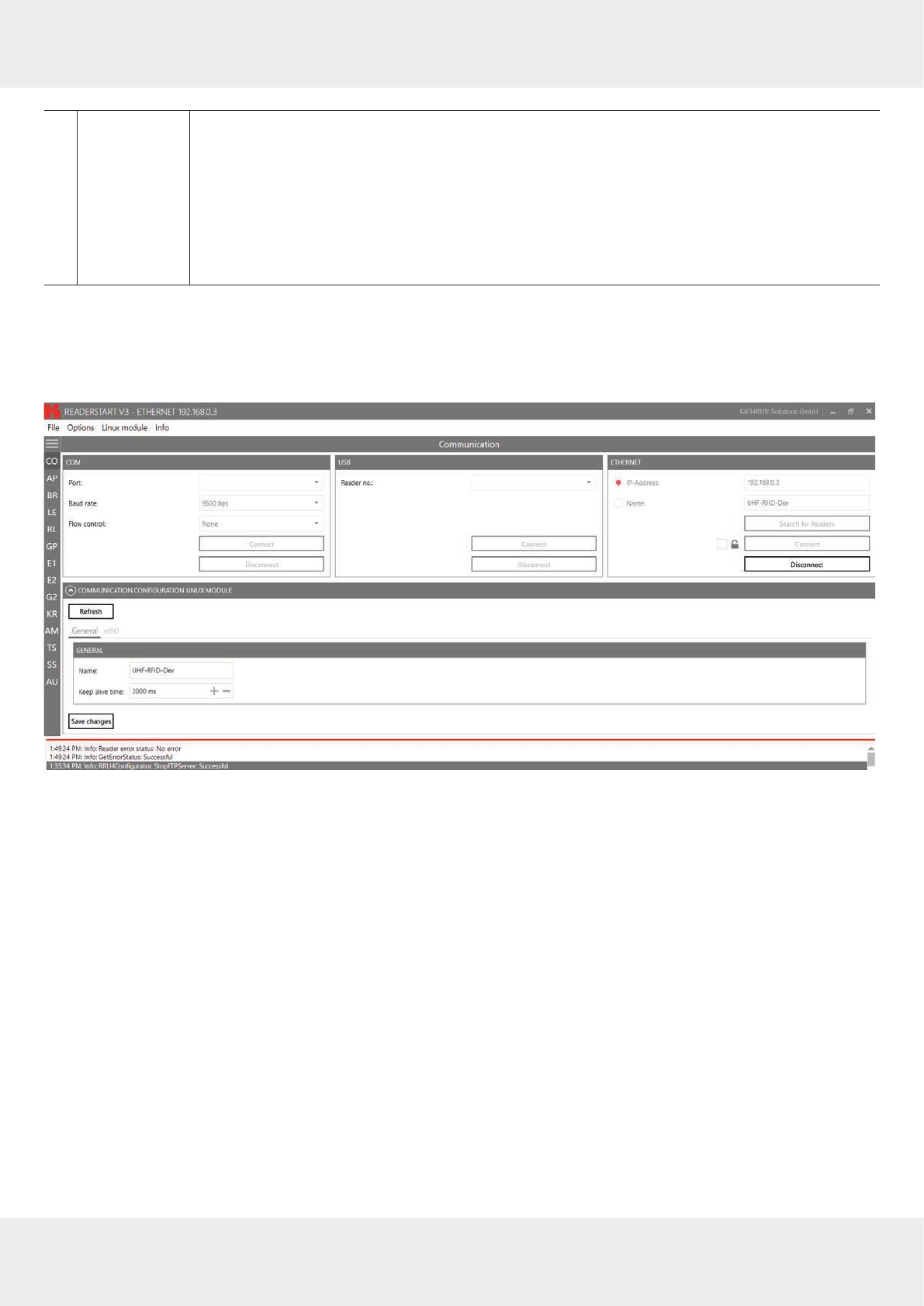
58 of 112
Operating the Reader Using the ReaderStart Software
⑥
Save to file
saves status messages in the txt. format
1. Click
Save to file
.
➯A pop-up windows appears requiring to select the location of the file.
2. Select the directory/folder.
3. Click
Save
.
➯A pop-up message
Saving done
appears.
4. Click
OK
to close the pop-up message.
14 Operating the Reader Using the
ReaderStart
Software
14.1 Communication
Fig. 26: Communication Tab
The communication tab groups together all the functions for establishing connections and configuring the Linux
module. The various communication connections are grouped in 3 sections:
●
COM
for serial connections via the COM port (RS232/485/422); only available in the M-ARU-ETH-E6 reader (order
number 52010198);
●
USB
for connections up to version USB 2.0; only available in the ERU-ETG-E4 (order number 52010190) and
ERU-ETG-U4 reader (order number 52010191);
●
Ethernet
for connections via TCP/IP;
●
Communication Configuration Linux Module
section to change the Ethernet setting; see
Communication Configuration Linux
Module, p.61
When the connection has been established, the program retrieves the information about the installed Linux module. It is
possible to view and change the configuration information via the
Communication Configuration Linux Module
.
14.1.1 Ethernet Section
The Ethernet connection is established by linking the reader into an existing network or by directly connecting the
reader and the control computer. To directly connect the reader to the PC, a cross-link cable is required, unless the LAN
interface on the PC supports
auto-mdi-x
. Alternatively, it is possible to use two standard patch cables and a switch.
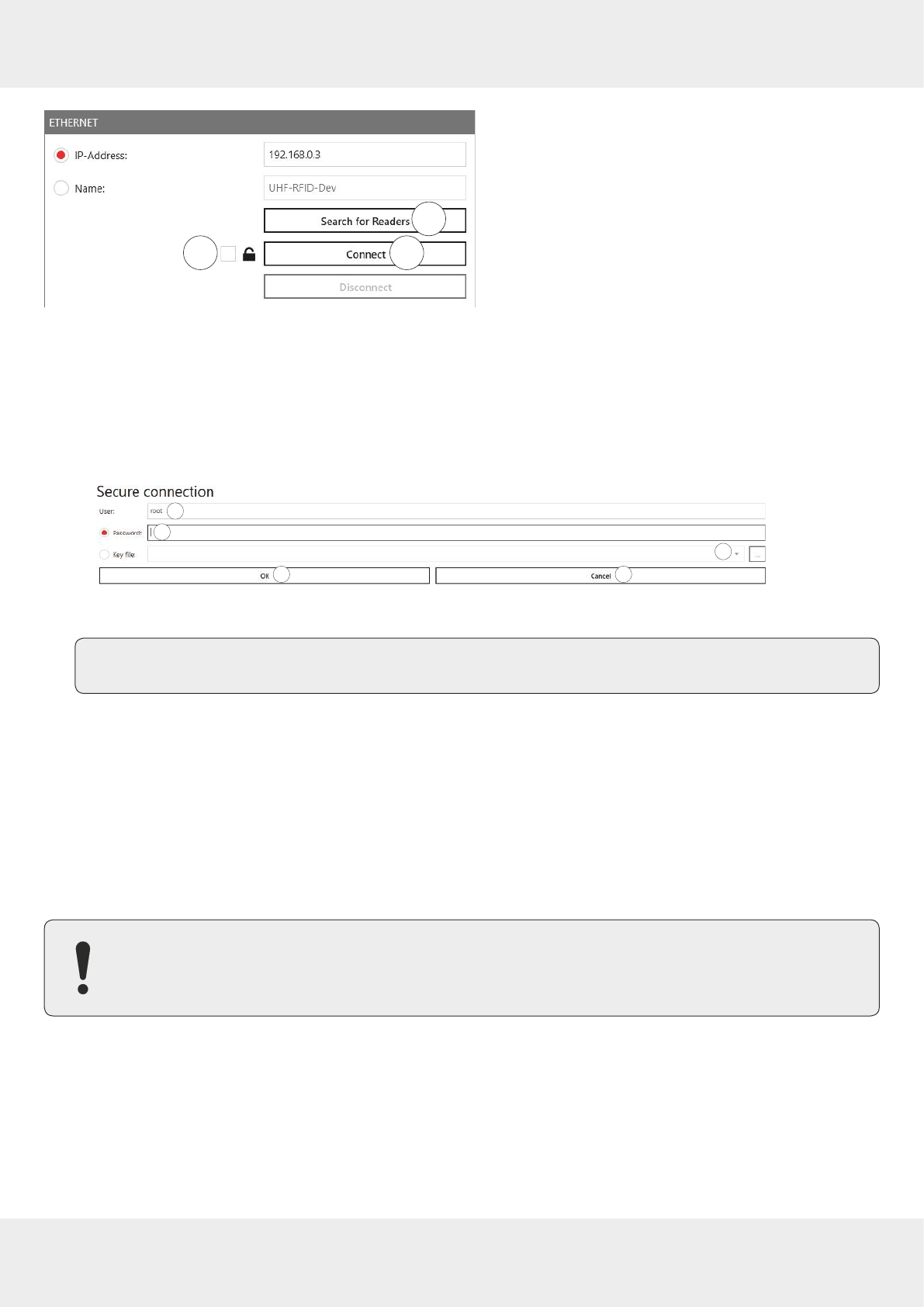
59 of 112
12
3
Fig. 27: Ethernet section
Establishing a Secure Connection
✔ The connection to the reader has not yet been established.
1. In the Ethernet section, click the box next to the lock symbol (① in
Fig. 27
).
2. Click
Search for Readers
(②) or
Connect
(③).
➯ The following pop-up window appears:
1
23
4 5
3. Type in the user name at
User
(①). The default user name is
root
.
4. Enter the default password
UHF-RFID-Dev
at
Password
(②).
Tip You can change the password under
Linux module
▶
Connection config
; see
Linux Module, p.51.
5. If you want to use the key file instead, click the box at
Key file
(③).
➯A pop-up window to select the key file opens.
6. Select the key file.
7. Click
OK
to establish the secure connection.
➯It is possible to configure the secure connection under
Linux module
▶
Connection config
; see also
Linux Module,
p.51.
Loading Factory Default Settings
When resetting the reader to factory default, the
ReaderStart
sends out a UDP broadcast cmd. It is only possible 30 sec-
onds after power rebooting.
Note that this command also resets the Linux module settings, such as Linux password, network name, IP
address, deactivates the auto start of the apps etc.
1. In the Ethernet section, click
Search for Readers
.
2. Select the reader onto which you would like to load the factory default settings.
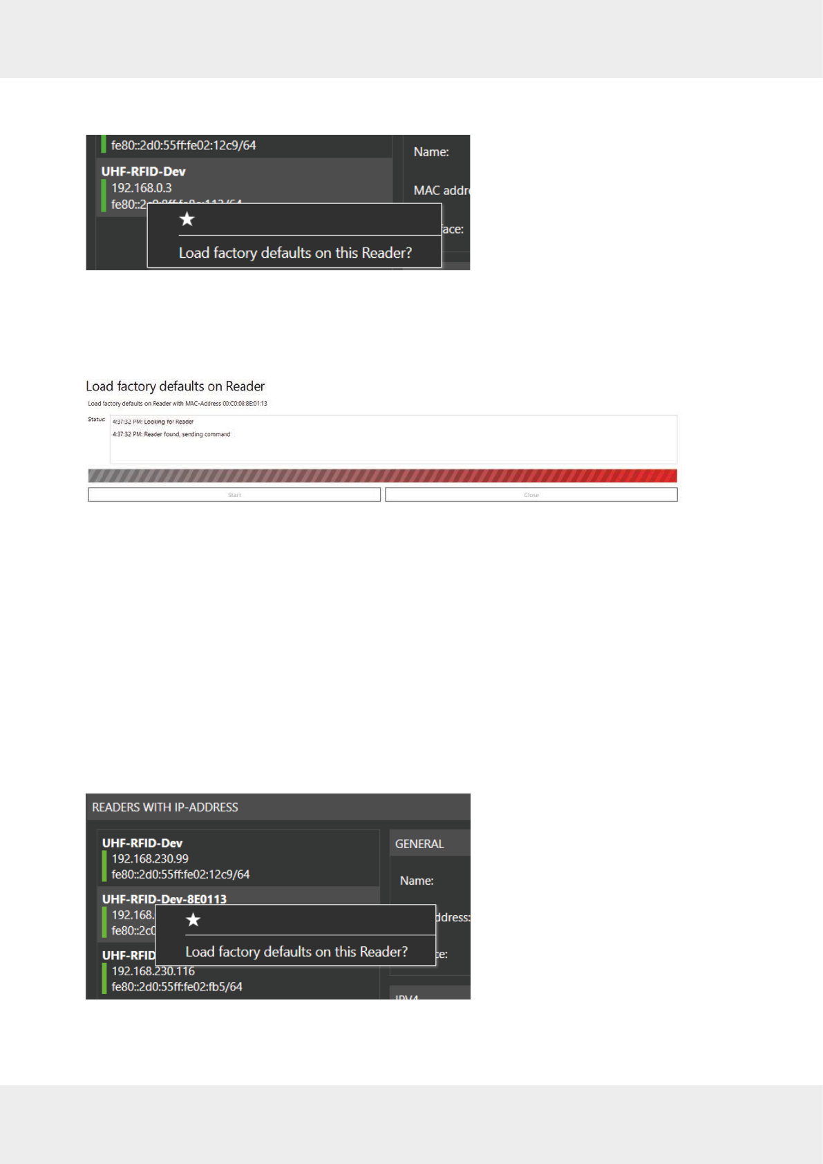
60 of 112
Operating the Reader Using the ReaderStart Software
3. Right-click on the reader.
➯The following pop-up message appears:
4. Click
Load factory defaults on this Reader
.
➯The pop-up message
Are you sure to load factory defaults on this reader
appears.
5. Click
Yes
to set the reader to the factory default settings.
Click
No
to cancel.
➯If you have clicked
Yes
, another pop-up window appears:
6. Click
Start
.
➯A pop-up message
Are you really sure to load factory defaults on this reader
appears.
7. Click
Yes
to set the reader to the factory default settings.
➯The status messages informing about the progress of the reset process are shown in the
Status
field of the
pop-up window, see examples in the figure above.
8. After the factory default settings have been loaded onto the reader, click
Close
.
Selecting a Favourite Reader
If there are many readers in the system and the user establishes connection to one reader more frequently than to the
others, it is possible to select the preferred reader as a favourite reader, placing it at the top of the reader list.
1. In the Ethernet section, click
Search for Readers
.
2. Select the preferred reader.
3. Right-click on the reader.
➯The following pop-up message appears:
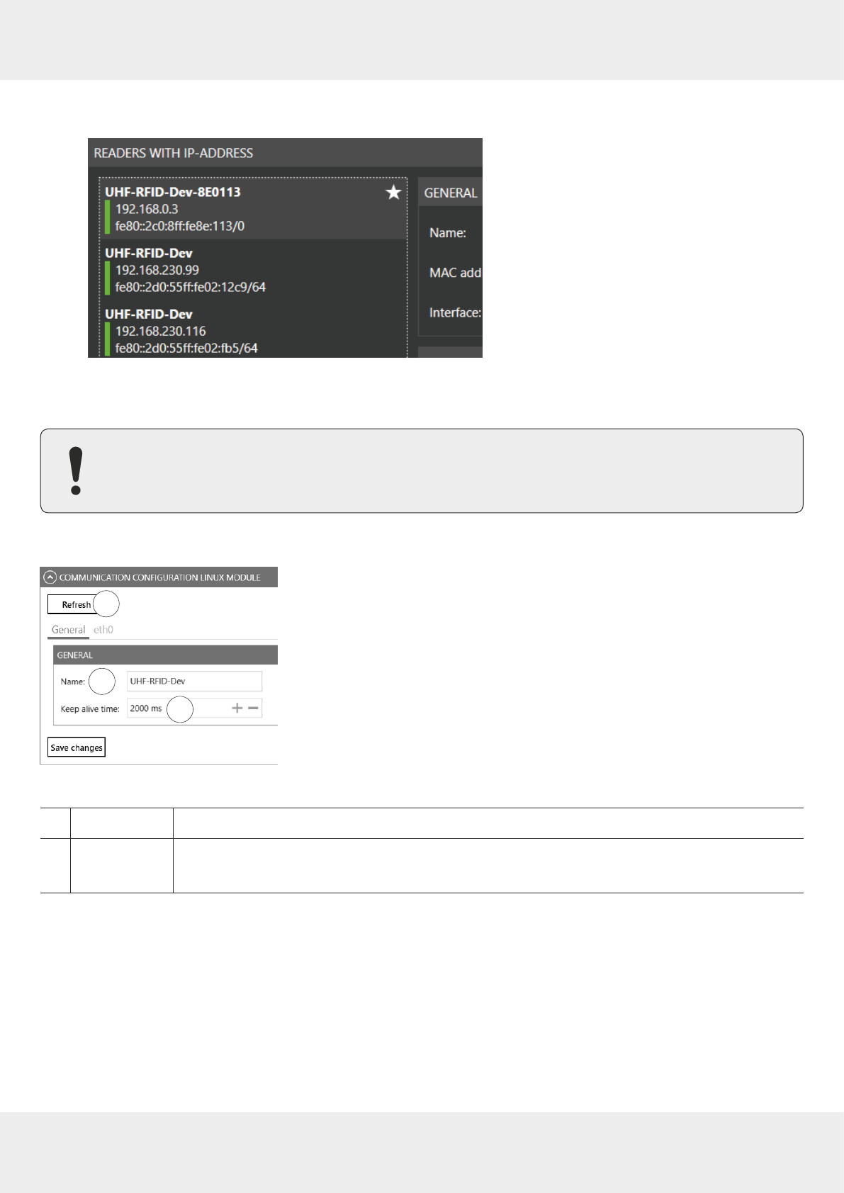
61 of 112
4. Click on the star.
➯The preferred reader is now placed at the top of the list, making it easier for the user to select it:
14.1.2 Communication Configuration Linux Module
Communication Configuration Linux Module has dierent options, depending on the reader type.
General
1
23
Fig. 28: Communication configuration Linux model: general
①
Refresh
reads the current settings of the communication configuration Linux module
②
Name
shows the host name of the reader which is logged onto the DNS server
It is possible to address the reader using this name as an alternative to the IP address.

62 of 112
Operating the Reader Using the ReaderStart Software
③
Keep alive time
specifies the intervals of time at which the reader sends a data packet to check whether the
receiver is still available
If the connection to the reader is broken, the reader shuts down the connection. If this parameter
is deactivated (0 ms), the socket is shut down only when the reader is restarted.
If no keep-alive time is set, it may happen that the reader cannot take up any further
connections because the existing connections have not been properly shut down, e.g.
following a breakage in the wire. In this case, it is necessary to restart the reader. It is
recommended to use the keep-alive time to check the connection between the reader
and PC.
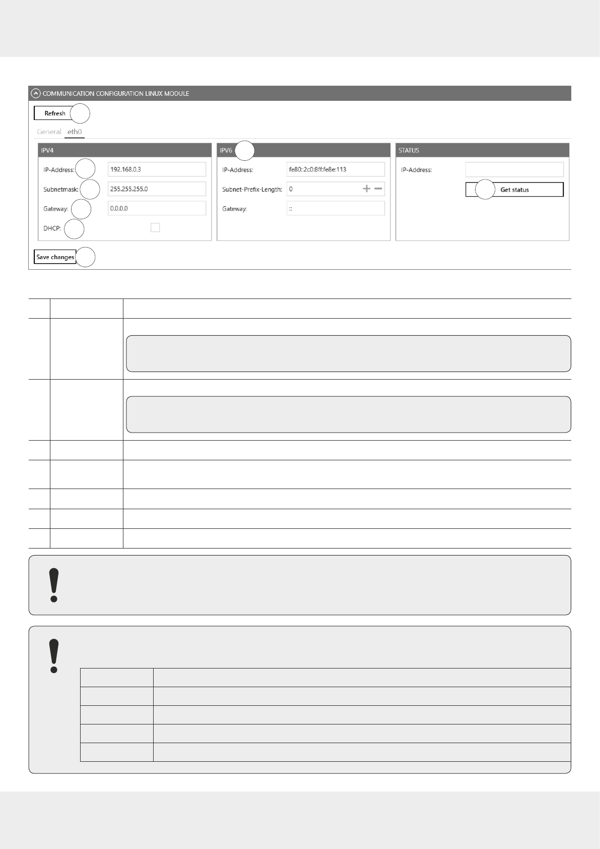
63 of 112
Ethernet
3
5
3
4
5
6
7
8
1
2
Fig. 29: Communication configuration Linux model: Ethernet
①
Refresh
reads the current settings of the communication configuration Linux module
②
IP address
manually issues the address
Tip It is only possible to use this parameter if the DHCP (⑥) is deactivated.
③
Subnet mask
manually issues a network mask
Tip It is only possible to use this parameter if the DHCP (⑥) is deactivated.
④
Gateway
enters the gateway
⑤
DHCP
activates/disactivates the automatic issuing of an IP address by a DHCP server; if the network has
a configured DNS server, it is also possible to use the host name of the reader.
⑥
IPv6
enters the second IPv6 address (the first IPv6 address is the link local address)
⑦
Status
shows the current reader IP address (eth0)
⑧
Save changes
saves changes
If the data relevant to the current connection (e.g. IP address) are changed, it may cause an error and the
connection is lost.
If the interface has been configured incorrectly, it is not possible to establish a connection to the reader.
►Note the following default configuration settings:
Name
UHF-RFID-Dev
IP address
192.168.0.1
Subnet mask
255.255.255.0
Keep-alive time
2000 ms
DHCP
deactivated
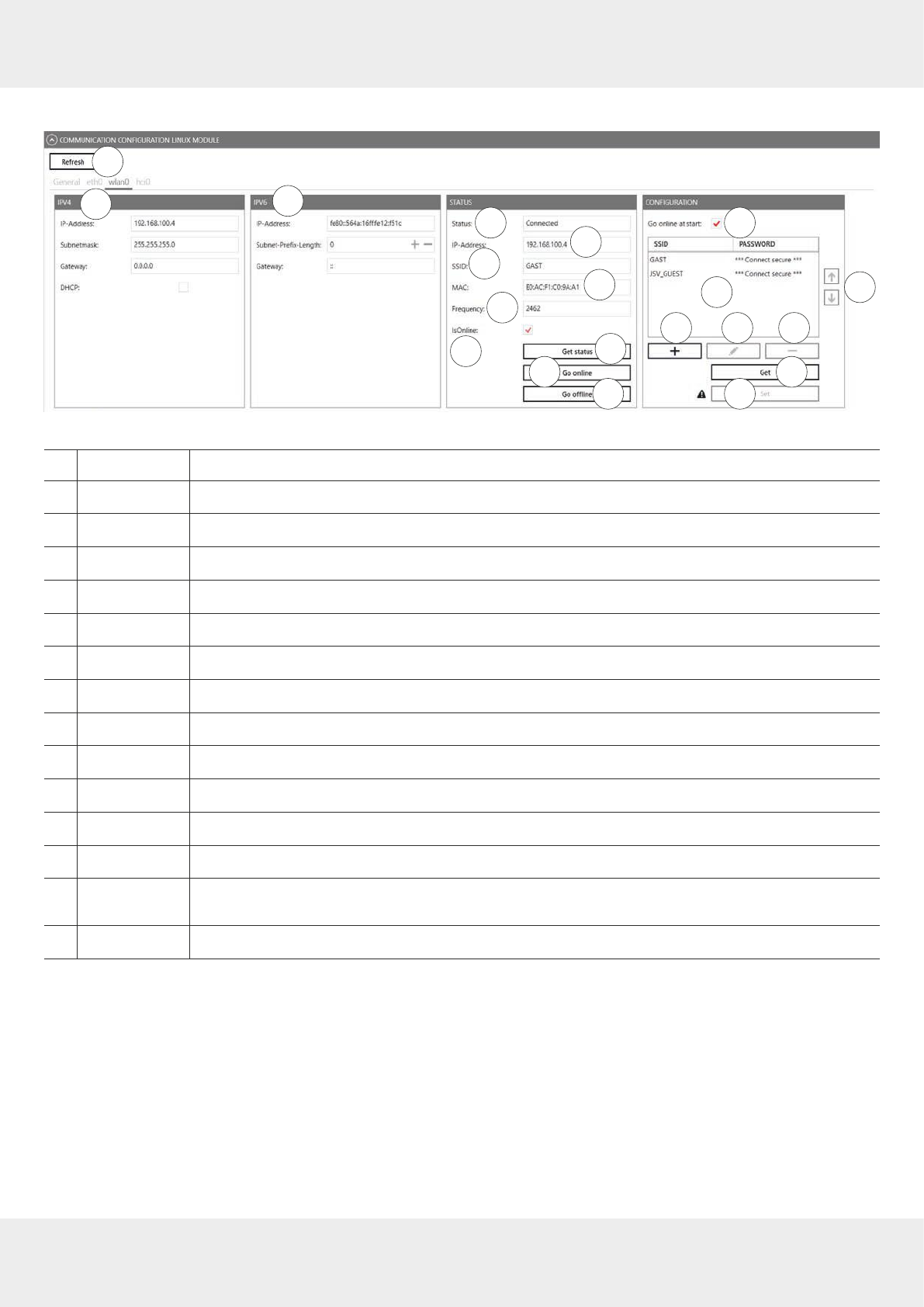
64 of 112
Operating the Reader Using the ReaderStart Software
Wi-Fi
3
5
345
67
8
1
10
2
911
12
13
14 15
16 17 18
19
20
Fig. 30: Communication configuration Linux model: Wi-Fi
①
Refresh
reads the current settings of the communication configuration Linux module
②
IP4
see
Fig. 29,p.63
③
IP6
enters the second IPv6 address (the first IPv6 address is the link local address)
④
Status
shows the status of the Wi-Fi connection
⑤
IP address
shows the current IP address
⑥
SSID
shows the name of the access point
⑦
MAC
shows the MAC address of the access point
⑧
Frequency
shows the frequency of the Wi-Fi connection
⑨
IsOnline
shows whether the Wi-Fi module is online
⑩
Get status
reads the current status of the Wi-Fi module
⑪
Go online
establishes the Wi-Fi connection
⑫
Go oine
interrupts the Wi-Fi connection
⑬
Go online at start
activates or deactivates the Wi-Fi connection as soon as the reader starts
⑭shows the list of the configured access points with SSID and password; the access points are
shown in the priority order
⑮changes the priority of the selected access point
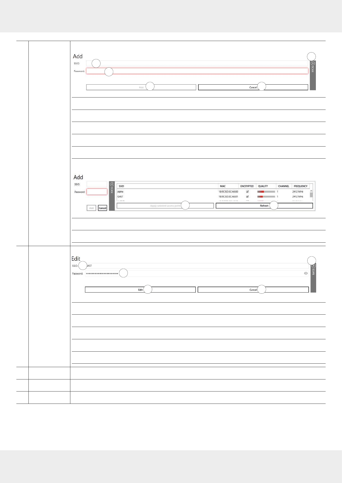
65 of 112
⑯
+
adds an access point
3
c
d
e
ab
ⓐenters the SSID of the access point
ⓑenters the password for the access point
ⓒopens the list with available access points
ⓓadds an access point
ⓔcancels the operation
►Click
Scan
to open the list with available access points:
3
fg
ⓕadds the SSID of the selected access point to ⓐ
ⓖupdates the list of available access points
⑰
edits the selected access point
3
b
d
1
c
e
ⓐchanges the SSID of the access point
ⓑchanges the password of the access point; only active when securely connected
ⓒopens the list with available access points
ⓓedits the access point
ⓔcancels the operation
⑱
–
deletes the selected access point
⑲
Get
reads the configured access points
⑳
Set
sets the access points; only active when securely connected
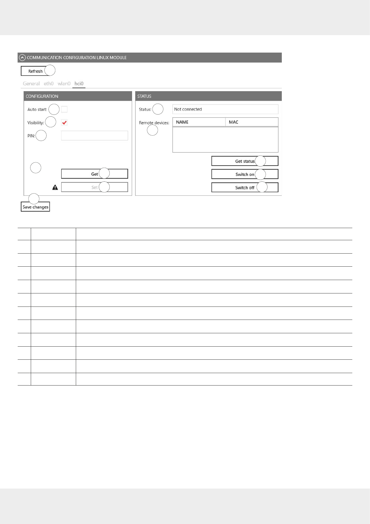
66 of 112
Operating the Reader Using the ReaderStart Software
Bluetooth
5
3
4
5
6
7
8
1
10
2
9
11
12
21
Fig. 31: Communication configuration Linux model: Bluetooth
①
Refresh
reads the current settings of the communication configuration Linux module
②
Auto start
activates or deactivates Bluetooth as soon as the reader starts
③
Visibility
activates or deactivates the Bluetooth visibility of the reader for other devices
④
PIN
sets the PIN for the Bluetooth connection; the default PIN is 4007
⑤
Get
reads the current Bluetooth configuration
⑥
Set
sets the con figuration of the Bluetooth connection; only active when securely connected
⑦
Status
shows the status of the Bluetooth connection
⑧
Remote devices
shows the remote devices connected to the reader
⑨
Get status
shows the status of the Bluetooth connection
⑩
Switch on
activates the Bluetooth module
⑪
Switch o
deactivates the Bluetooth module
⑫
Save changes
saves changes
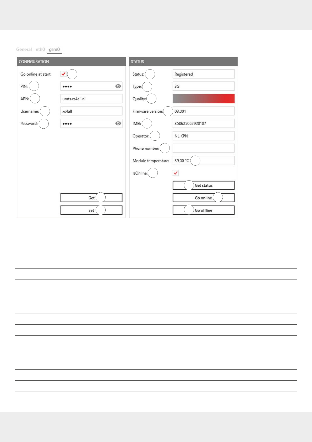
67 of 112
Mobile Communication Interface (2G/3G)
5
3
4
5
6
7
8
1
10
9
2
11
1213
14
15
16
17 18
19
Fig. 32: Communication configuration Linux model: mobile communication interface (2G/3G)
①
Go online at start
activates or deactivates the GSM connection as soon as the reader starts
②
PIN
enters the PIN code for the SIM card
③
APN
enters the access point name from the provider
④
User name
enters the access point name from the provider
⑤
Password
enters the access point name from the provider
⑥
Get
reads the current configuration of the GSM module
⑦
Set
sets the configuration of the GSM module; only active when securely connected
⑧
Status
shows the status of the GSM connection
⑨
Type
shows the GSM connection type
⑩
Quality
shows the quality of the GSM connection
⑪
Firmware version
shows the firmware version of the GSM module
⑫
IMEI
shows the serial number of the GSM module
⑬
Operator
shows the operator of the GSM connection
⑭
Phone number
shows the phone number of the SIM card

68 of 112
Operating the Reader Using the ReaderStart Software
⑮
Module
temperature
shows the temperature of the GSM module
⑯
IsOnline
shows whether the GSM module is online
⑰
Get status
reads the current status of the GSM module
⑱
Go online
establishes the GSM connection
⑲
Go oine
interrupts the GSM connection
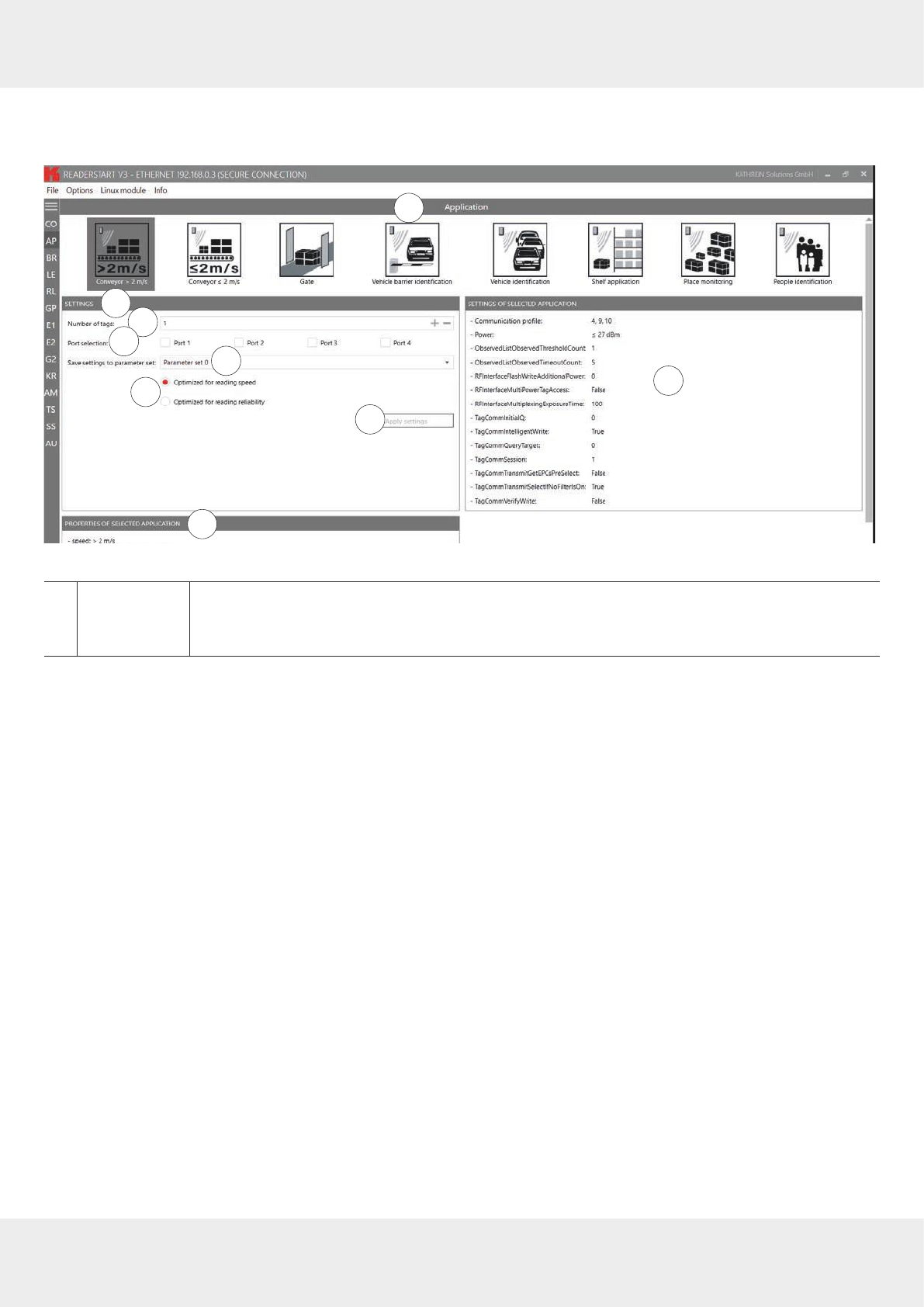
69 of 112
14.2 Application
The Application tab enables quick and easy configuration of the Kathrein RFID Reader for a selected application.
e
1
2
3
a
bc
d
4
Fig. 33: Application Tab
①
Application
selects between the available applications represented visually by means of labelled pictograms
►Click on a pictogram to select the application.
➯The selected pictogram is marked in a darker colour, in
Fig. 33
it is
Conveyor > 2 m/s.

70 of 112
Operating the Reader Using the ReaderStart Software
②
Settings
changes setting of the selected application
ⓐnumber of the expected tags
ⓑ
selects the antenna to be used
►Check Ports 1-4 to select the antenna port. It is possible to select one, several or all
ports.
ⓒselects the parameter set in which the configuration is saved
ⓓ
sets the values for max. reading speed or max. reading reliability
►Click
Optimised for reading speed
or
Optimised for reading reliability
.
➯The values in
Settings of selected application
(③ in
Fig. 33
) change.
When the max. read frequency is set (
Optimised for reading speed
is activated), the number
of readings is maximised. In this case, the same tag can be read several times, because
all tags will be reset in the inventory so that they will respond again. Because of reading
the same tag multiple times, in a scenario of moving tags it could happen that not all the
tags crossing the antenna field are read. The frequency of detection of the same tag is
increased. In some cases, the time allowed for detecting the tags may be insucient, so
that some transponders are not detected.
When the max. read reliability is set (
Optimised for reading reliability
is activated), tags that
have already been read are not read again in the next inventory, provided they are still
being supplied with power. This means that only the tags which have not yet been regis-
tered are detected. This way, the probability that all tags are read is increased.
ⓔ
saves the settings that have been made as the settings for the selected application in the
selected parameter set. The programme resets the settings to the factory settings first,
thus overwriting the previous configuration.
If the settings have been reset, the
Apply settings
button briefly glows green and a success
message is displayed in the
Status
field of the programme interface.
If case of a fault, the
Apply settings
button briefly glows orange to indicate a warning or red
to indicate an error. If the fault has been caused by a missing entry, the field lacking the
entry also glows red. A warning/error description is displayed in the
Status
field.
After the settings have been loaded, it is possible to go to the
Basic reading
tab and to start
the read process.
③
Settings of
selected
application
shows the settings that have been made for the selected application in the selected parameter
set
④
Properties
of selected
application
shows the properties of the selected application
Tip The read rate is influenced by many parameters. In addition to the selected broadcasting profile with the
respective data rates, there are also application-specific data, e.g. how many tags the reader should expect
in the field. You can optimise these parameters using the
Expert settings 1
and
2
.
►If you are unsure whether the settings you have chosen are best suited for your application, contact
KATHREIN Solutions support at https://www.kathrein-solutions.com/support/overview.

71 of 112
14.2.1 Available Applications
When the application is selected, the properties and the settings of the selected application are displayed in the respec-
tive fields.
The applications available for selection in version 3.00 of the
ReaderStart v3
are shortly described in the following chapters.
Conveyor belt > 2 m/s
●for detecting individual tags in the antenna field on a conveyor belt moving at more than 2 m/s
●the distance between the tags and the antenna must be only a few centimetres
Conveyor belt ≤ 2 m/s
●for detecting and describing individual tags in the antenna field on a conveyor belt moving at a speed less than or
equal to 2 m/s
●the distance between the tags and the antenna must be only a few centimetres
Gate
●for detecting multiple tags in the antenna field as they pass through a gate
Vehicle Barrier Identification
●for detecting and describing individual tags in the antenna field which are not moving
●the distance between the tags and the antenna must be less than a few metres
Vehicle Identification
●for detecting and describing multiple tags in the antenna field which are moving at a speed of more than 14 m/s
●the distance between the tags and the antenna must be less than a few metres
Shelf Application
●for detecting and describing individual tags in the antenna field which are not moving
●the distance between the tags and the antenna must be less than 1m
Place Monitoring
●for detecting and describing multiple tags in the antenna field which are not moving
●the distance between the tags and the antenna must be less than 1m
Personal Identification
●for detecting multiple tags in the antenna field which are moving at a speed of not more than 3 m/s
●the distance between the tags and the antenna must be less than 1m
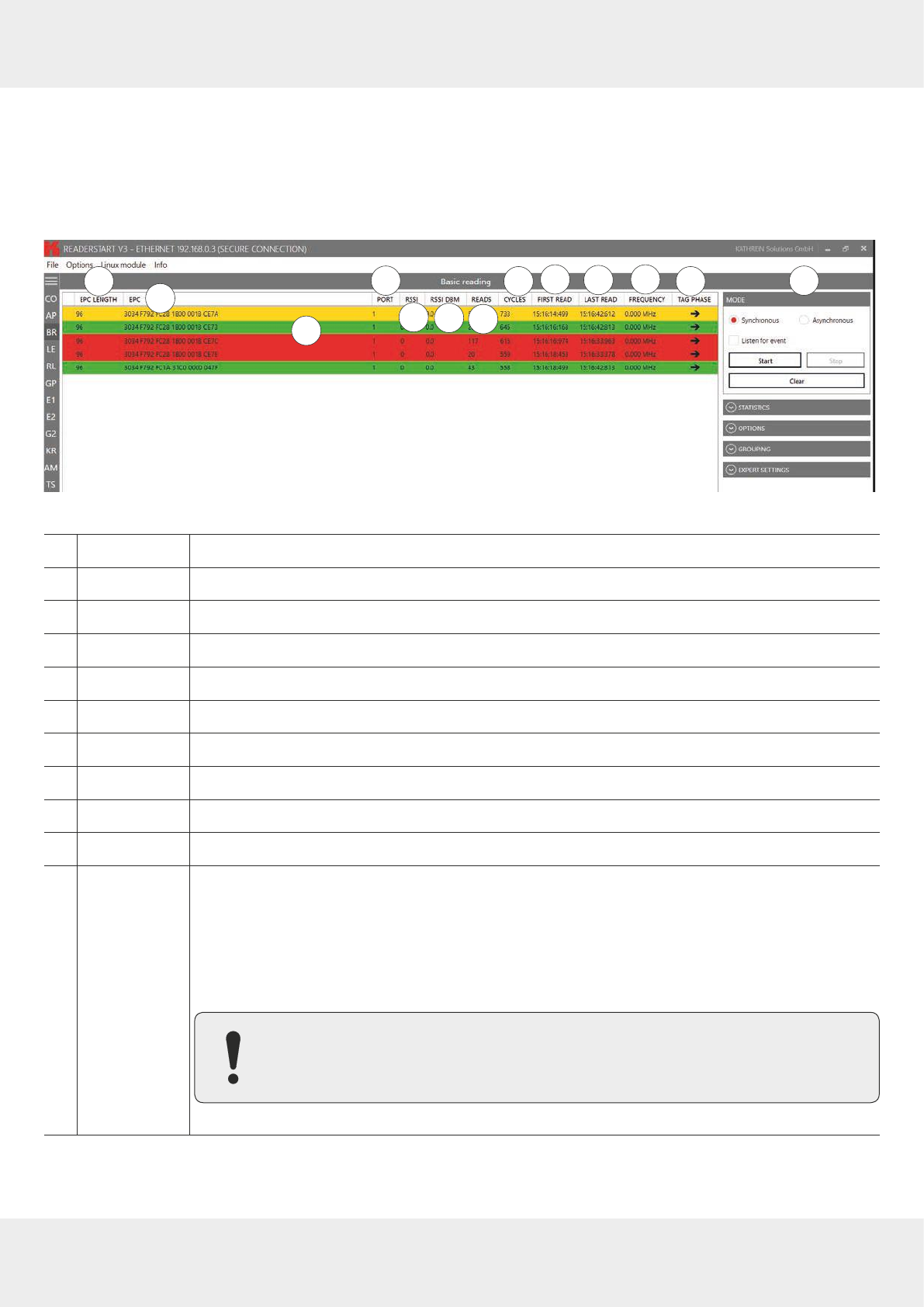
72 of 112
Operating the Reader Using the ReaderStart Software
14.3 Basic Reading
This tab is divided into two parts, the left part contains a table with information about the read tags (Ⓐ in the figure
below), the right part (Ⓑ) shows the statistics as well as options to control the reading process, described in the chap-
ters to follow.
The appearance and disappearance of a tag is shown in colour for better visual eect. When a tag appears in the field,
the row is represented by the green tag information, when it disappears, the row is red.
A
23
1456
78910 11 B
Fig. 34: Basic reading
①
EPC length
indicates the length in bits of the EPC; valid lengths 0–496
②
EPC
EPC of the tag in the hexadecimal representation
③
Port
antenna port at which the tag is read; valid values 1–4
④
RSSI
unitless (shown as having no units) signal strength of the tag response
⑤
RSSI DBM
shows the RSSI value in dBm
⑥
Reads
shows how many times this tag has been read successfully
⑦
Cycles
indicates how often an inventory has been started
⑧
First read
timestamp of the first tag reading
⑨
Last read
timestamp of the last tag reading
⑩
Frequency
shows the used transmission frequency
⑪
Tag phase
shows the tag phase in form of a rotating pointer
This parameter is used to distinguish between stationary and moving transponders.
If the transponder is moving away from the antenna, the pointer rotates counterclockwise, and
clockwise, if the transponder is moving towards the antenna.
The movement speed is directly proportional to the rotational speed of the pointer.
In a full rotation of 360°, the transponder travels a distance of 17cm.
Note that the reader has to change the transmission frequency every 4 seconds,
causing a phase jump.
The tag phase is also shown in the TagScan monitor; see
TagScan, p.103
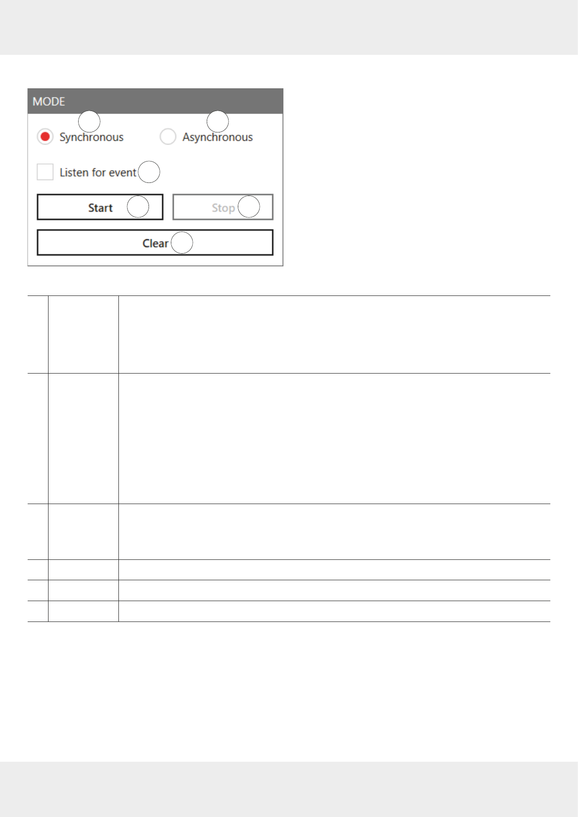
73 of 112
14.3.1 Mode
2
3
1
4 5
6
Fig. 35: Basic reading: mode
①
Synchronous
allows the facility to switch the carrier o during the idle times, saving power
This mode is intended for applications in which the requirements for timing are not very
demanding. The inventory of the tags is performed across all the antennas that are configured.
Once all the tags in the field have been read on the last antenna, data are sent to the PC. The PC
automatically retriggers the inventory of the tags.
②
Asynchronous
is intended for applications for which maximum performance is required
The reader starts the inventory as quickly as possible, and at the end of an inventory it does not
deliver every tag that was read to the PC, but only those that have recently appeared in the field
or left it. This way, the time required for communication between the reader and the client is
minimised.
The timing of when a tag was reliably read in the field and when the tag no longer appears in the
field can be defined more precisely using parameters.
►For more details of the ObservedThresholdCnt and ObservedTimeoutCnt parameters, refer to the
Con-
figurational manual reader
.
③
Listen for event
deactivates or activates waiting for the result of the command executed by an external trigger
and shows the result in Ⓐ in
Fig. 30
When deactivated, there is no waiting process and it is possible to start the reading process at
any time.
④
Start
starts the reading
⑤
Stop
stops the reading
⑥
Clear
deletes the reading results from the table on the left (Ⓐ in
Fig. 34,p.72
)
14.3.2 Starting and Stopping the Reading
✔ All the settings have been applied and the mode selected.
►Click
Start
(④ in
Fig. 35
) to start the reading.
►Click
Stop
(⑤) to stop the reading.
►Click
Clear
(⑥) to remove all tag entries from the table (Ⓐ in
Fig. 34,p.72
).
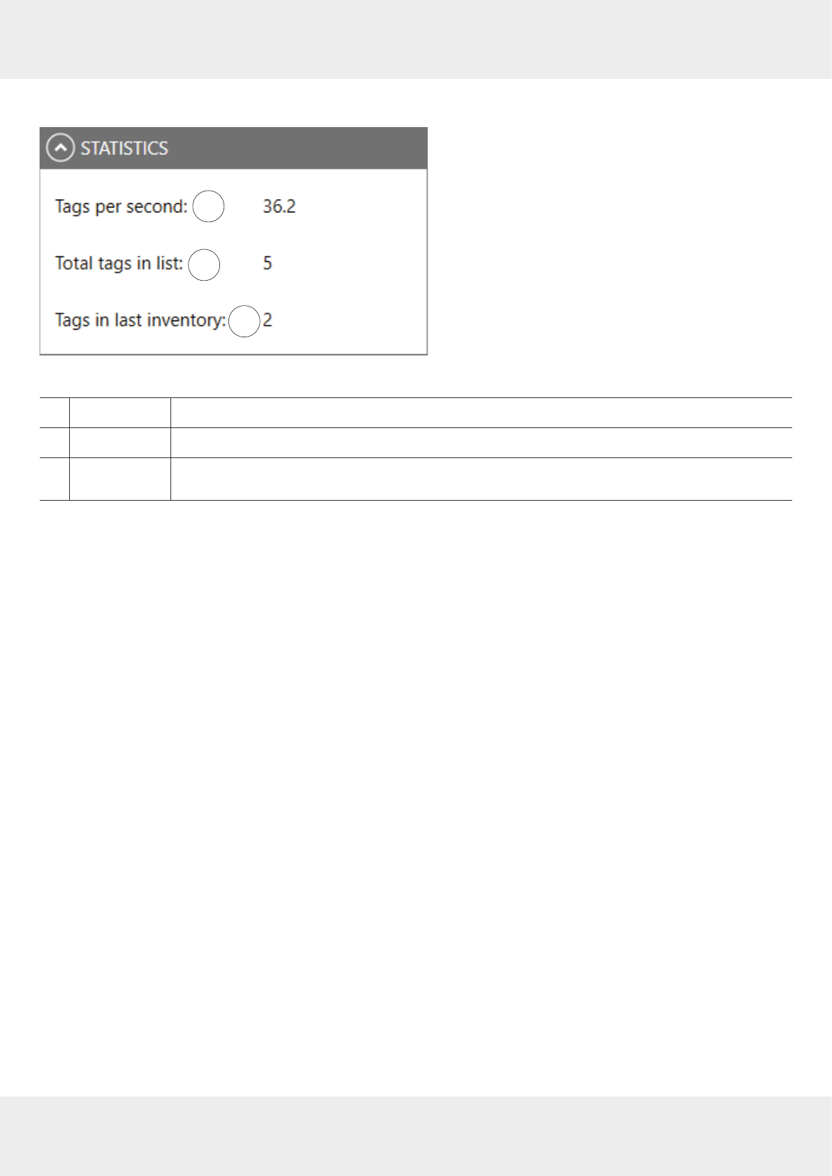
74 of 112
Operating the Reader Using the ReaderStart Software
14.3.3 Statistics
2
3
1
Fig. 36: Basic reading: statistics
①
Tags per second
displays the current reading performance
②
Total tags in list
shows the total number of tags in the list
③
Tags in last
inventory
shows number of tags detected in the last inventory
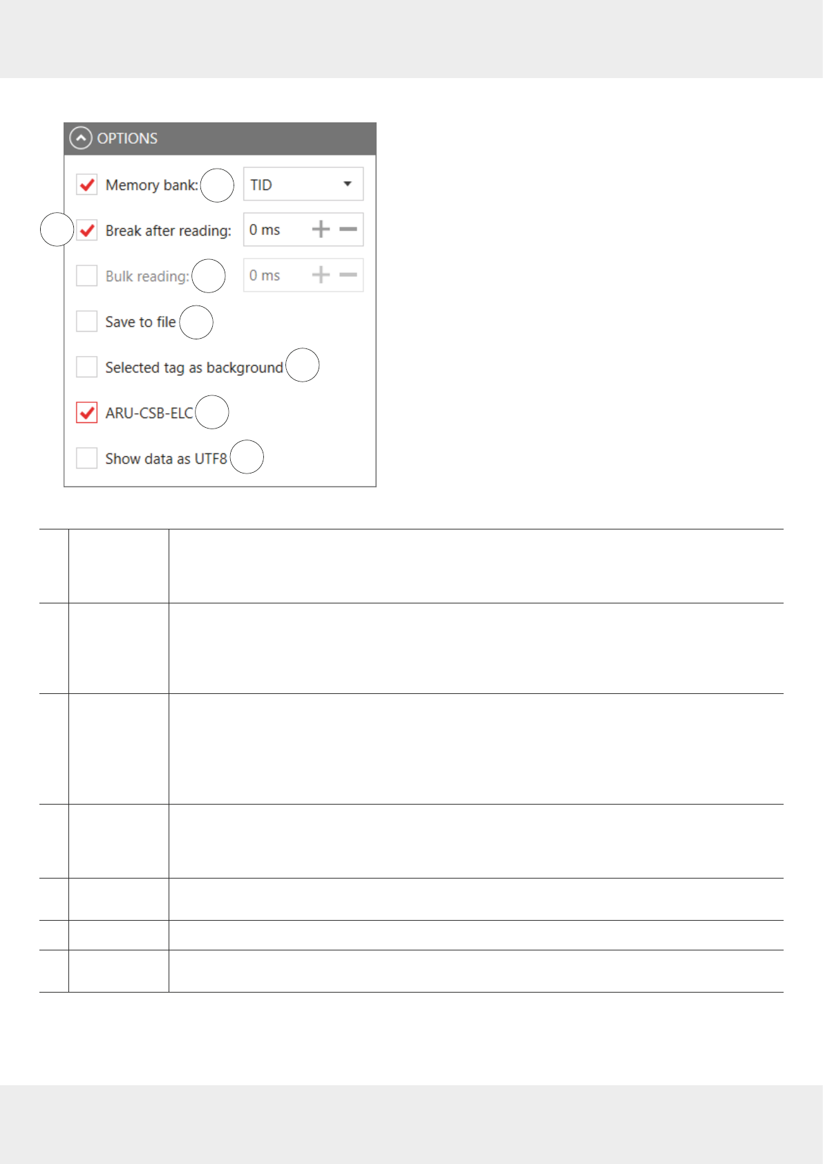
75 of 112
14.3.4 Options
2
3
1
4
5
6
7
Fig. 37: Basic reading: options
①
Memory bank
selects between
RFU
,
EPC
,
TID
and
User
memory banks
►Click on the arrow to open a drop-down list to select a memory bank.
►Click
Save to file
(④) to store the values
RFU
,
EPC
,
TID
and
User
in a CSV file.
②
Break after
reading
specifies the duration of the break between two inventories in milliseconds
During the break, the carrier can be deactivated.
►For more information about switching o the carrier, refer to
Configuration Manual for Kathrein RFID
UHF Readers
.
③
Bulk reading
sets the time in milliseconds after which the result lists of an inventory is sent to the PC
To keep the time between inventories as short as possible in the synchronous mode, data trans-
mission between the inventories can be dispensed with. That means that the reader saves all the
tags that it finds in the field in its internal RAM and sends them to the PC after the time set in
Bulk
reading
.
④
Save to file
saves the data displayed at (Ⓐ in
Fig. 34,p.72
)
►Click
Change path to log file
to select or change the location where the information is saved.
►Right-click on
Save to file
to open or delete the file.
⑤
Selected tag as
background
changes the basic reading interface background to the colour of the selected tag row
⑥
ARU-CSB-ELC
activates the additional presentation for an ARU-CSB-ELC antenna
⑦
Show data as
UTF8
shows tag data in the UTF8 format
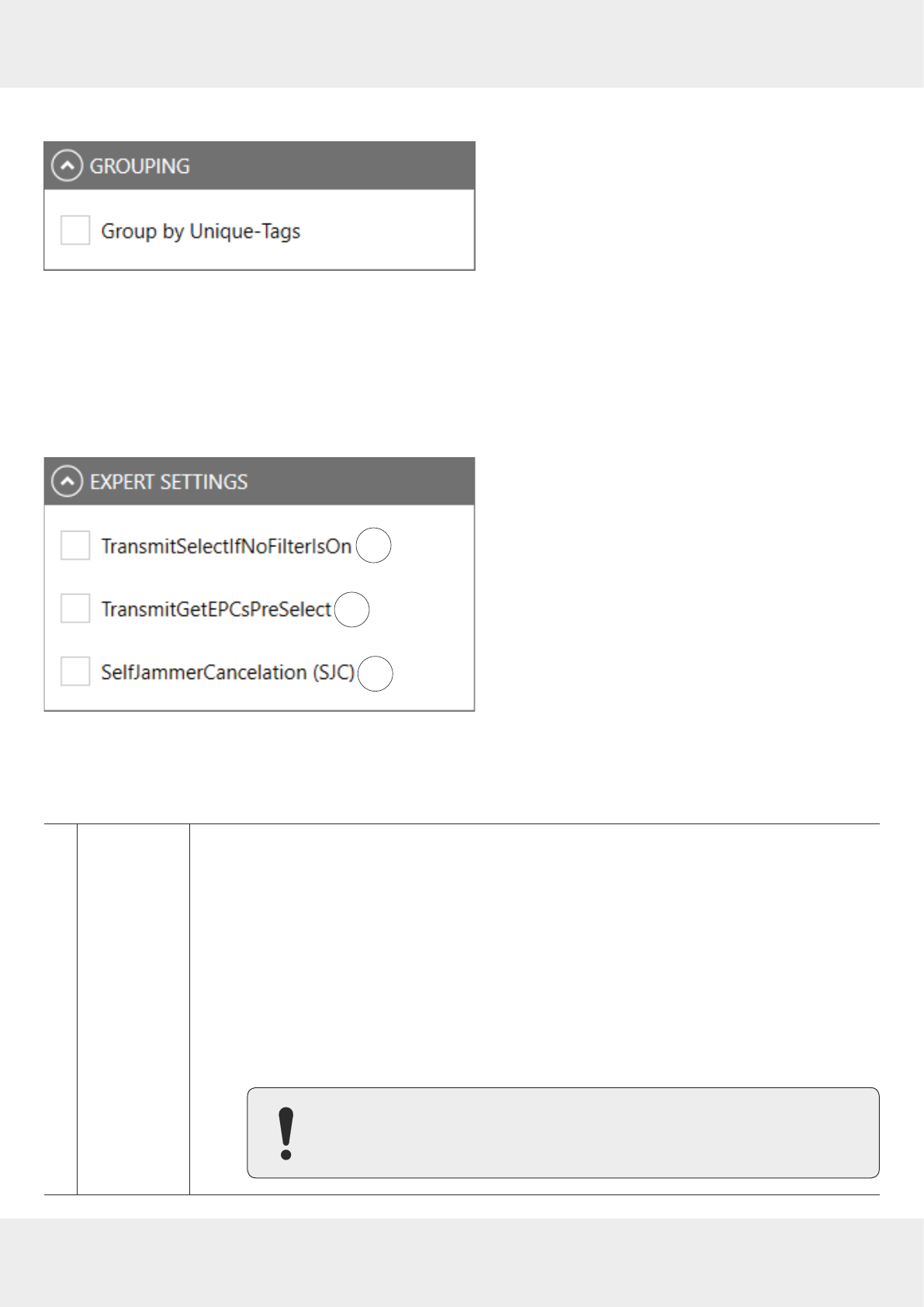
76 of 112
Operating the Reader Using the ReaderStart Software
14.3.5 Grouping
Fig. 38: Basic reading: grouping
It is possible to sort the read result by means of unique tags. This is useful in multi-antenna applications.
If, for example, in a gate application with 4 antennas, a palette of 100 tags is read, the maximum number of the read
results is 400. However, not all tags are read by all antennas, therefore, the read result will be about 250.
►Check
Group by unique tags
to find out how many dierent tags have been read.
14.3.6 Expert settings
2
3
1
Fig. 39: Basic reading: expert settings
①
TransmitSelectIf-
NoFilterIsOn
resets all the tags that are defined in the field at a given time
When the tag count is very high (> 200), it is possible to speed up the detection of the tags by
commanding the reader to change to new
Select command
; see
EPCglobal Gen2 Specification
. It is pos-
sible to test it in the menu
Expert Settings
.
►Check
TransmitSelectIfNoFilterIsOn
.
➯A "select" is sent in each inventory, i.e. all the tags that are defined at this time in the field
are reset.
However, it can happen that the tags that have been read already are reset and re-recorded again.
To capture only new tags, it is necessary to to prevent a renewed "select".
►Uncheck
TransmitSelectIfNoFilterIsOn.
➯The tags are read once. This way, no time is lost due to a reread.
Note that it is not possible to retrieve tags in which the read operation had
been interrupted. This way, it may happen that not all the tags are read. Keep
that in mind when unchecking this parameter in order to achieve top results.
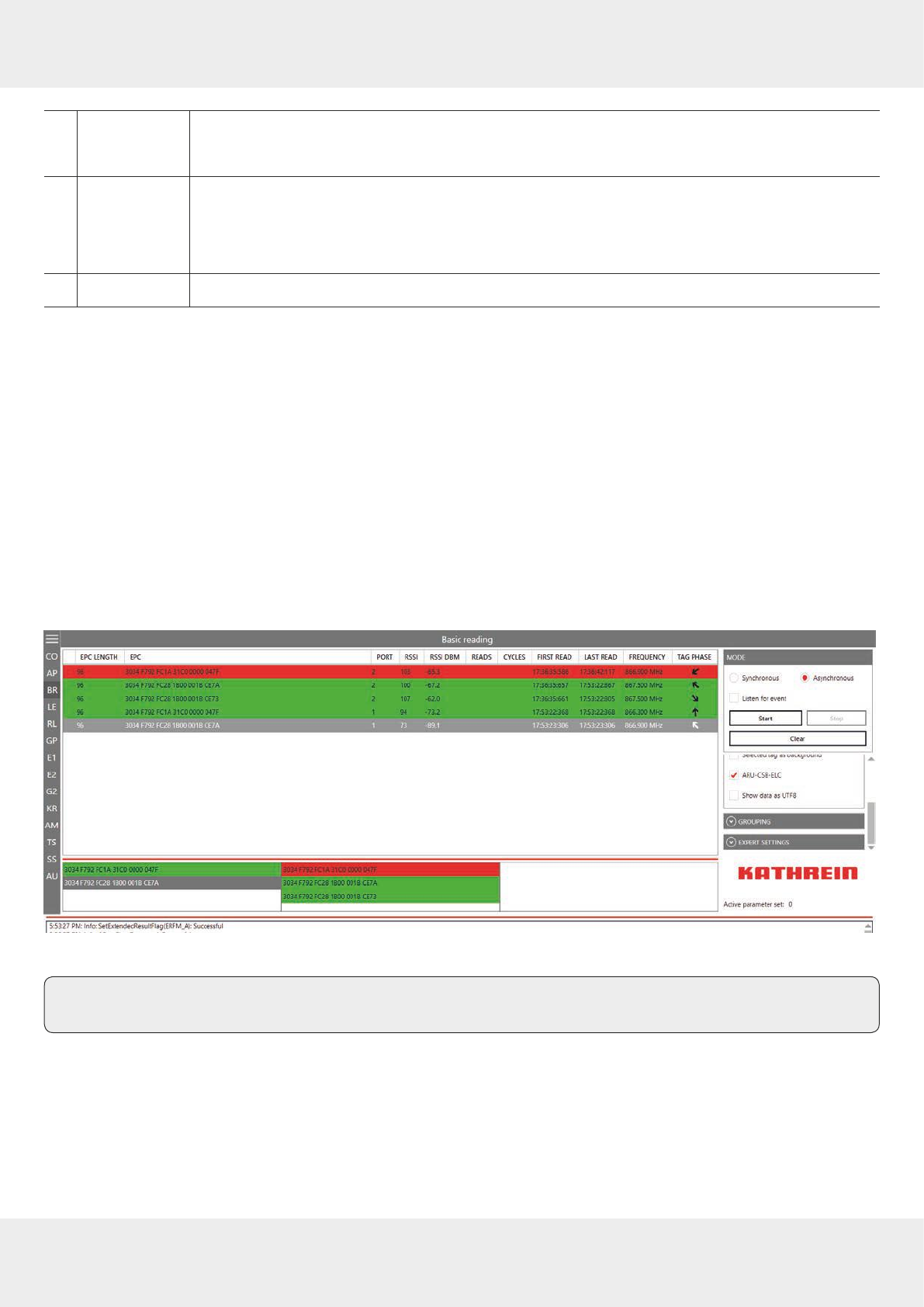
77 of 112
②
Transmit-
GetEPCsPreSe-
lect
see Chapter TransmitGetEPCsPreSelect in
Configuration Manual for Kathrein RFID UHF Readers
③
SelfJammerCan-
celation (SJC)
activates/deactivates the optimal receiver sensitivity of the reader
This process might be necessary in an industrial environment with increased reflection, e.g. due
to metallic structures. However, this process is very time-consuming and slows down the tag
detection.
④
SJC Scan interval
sets the interval after which the
SelfJammerCancelation
process is executed
14.3.7 ARU-CSB-ELC Antenna Reader Unit
The ARU-CSB-ELC antenna reader unit with the integrated 30° wide-range antenna is controlled by the @KRAI reader.
The antenna can be switched to three dierent beam positions.
Each individual position can be selected fix or all selected positions are exchanged dynamically. The user will get a read
result with an indication of the position for the run of a tag (left, centre, right).
Using the time sequence of the reading results of these positions, it is possible to determine the direction of a tran-
sponder. Tags which do not change their position are captured as well.
The ARU-CSB-ELC antenna is used, e.g. in gate applications. In addition to the "simple" detection that a tag has passed
the gate, the direction of the movement is displayed as well. This can be used, for example, to book a delivery of goods
as an input or output immediately.
Having selected the
ARU-CSB-ELC
(⑥ in
Fig. 37,p.75
) under
Options,
the lower part of the screen shows the spatial alloca-
tion of a transponder:
Fig. 40: Basic reading: ARU-CSB-ELC
Tip The WIRA-30-CSB-KRAI antenna is presented in a similar way and is shown under
Options
when connected.
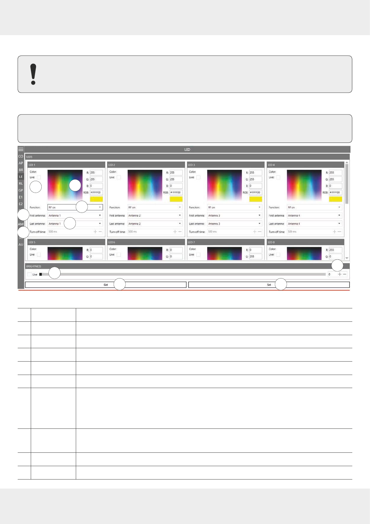
78 of 112
Operating the Reader Using the ReaderStart Software
14.4 LED
Not all readers support the functionality with 12 LEDs; all readers have at least 4 LEDs. Please check the
reader data sheet for information.
In this tab, it is possible to assign various functions to the 12 LED channels. It is possible to activate other parameters,
depending on the selected function.
Tip As supplied to customer, the first 4 LEDs are allocated to antennas 1–4, LED 5 is allocated to GSM, LED 6 to
KRAI, LED 11 and LED 12 to Bluetooth and Wi-Fi, respectively. It is possible to customise this allocation.
2
3
1
45
6
78
9 10
Fig. 41: LED
①
Live
shows the changed LED colour in real time
②shows RGB values
③
Function
selects between the functions described in
Selecting Functions, p.79
④
First antenna
the first antenna for the selected function
⑤
Last antenna
the last antenna for the selected function
⑥
Turn-o time
sets the time for how long LED is on for the selected function
⑦
Brightness (live)
changes the LED brightness for all active LEDs (between 0 (auto brightness determined by the inte-
grated light sensor) and 100)
►
Move the brightness position along the bar to change the brightness of the LED.
➯
The number at
⑧ changes.
⑧
changes the LED brightness (between 0 and 100)
►
Click
+
or
–
to change the brightness of the LED.
⑨
Get
shows the current settings for all LEDs
⑩
Set
sets the new settings for all LEDs for which the settings have been altered
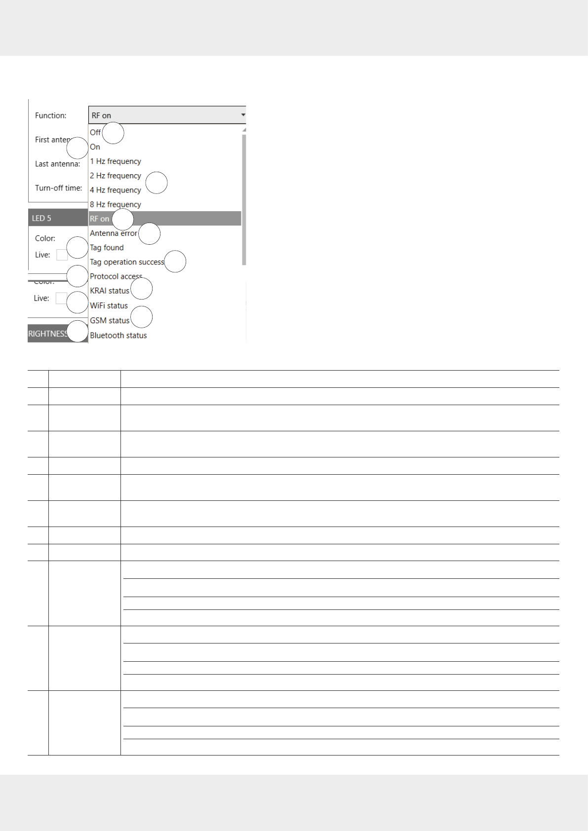
79 of 112
14.4.1 Selecting Functions
►Click on the arrow (③ in
Fig. 41,p.78
) to select between the following functions:
2
3
1
45
67
10 11
9
12
8
Fig. 42: LED: functions
①
O
deactivates the LED
②
On
activates the LED (always on)
③
1 Hz
–
8 Hz
frequency
LED flashes at a frequency of 1/2/4/8 Hz
④
RF on
LED lights up for
Turn-o time
milliseconds if a radio frequency is present at the antenna
First
antenna
to
Last antenna
has been successful
⑤
Antenna error
LED lights up for
Turn-o time
milliseconds if a error occurs at the antenna
First antenna
to
Last antenna
⑥
Tag found
LED lights up for
Turn-o time
milliseconds as soon as a tag has been found at the antenna
First
antenna
to
Last antenna
⑦
Tag operation
success
LED lights up for
Turn-o time
milliseconds if a tag operation at the antenna
First antenna
to
Last
antenna
has been successful
⑧
Protocol access
enables the protocol to switch the LED on and o
⑨
KRAI status
shows whether a @KRAI antenna is connected to the reader
⑩
Wi-Fi status
shows the Wi-Fi status
flashing trying to connect
permanently lit connected
o Wi-Fi disabled
⑪
GSM status
shows the GSM status
flashing trying to connect
permanently lit connected
o Wi-Fi disabled
⑫
Bluetooth status
shows the Bluetooth status
flashing trying to connect
permanently lit connected
o Wi-Fi disabled
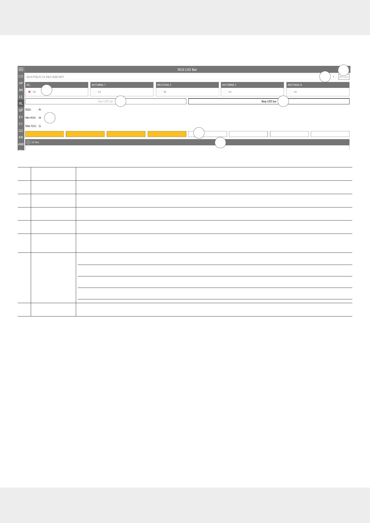
80 of 112
Operating the Reader Using the ReaderStart Software
14.5 RSSI LED Bar (received signal strength indicator)
This menu is used to determine the strength of the received signal.
2
3
1
4 5
6
78
Fig. 43: RSSI LED Bar
①
Refresh
updates the number of detected tags
②selects a tag from the number of the detected tags by means of the drop-down menu
③
All/Antenna 1
–
4
selects whether the tag has to be read on all antennas or only one antenna
④
Start LED bar
measures the signal strength
⑤
Stop LED bar
stops the measurement
⑥
RSSI, Min. RSSI,
Max. RSSI
shows the current RSSI value as well as the minimum and the maximum RSSI values
⑦
shows the read range by means of the coloured bars
green
signal strength is high (high RSSI value)
yellow
signal strength is medium (medium RSSI value)
red
signal strength is low (low RSSI value)
⑧
Details
shows detail information about RSSI for each antenna and property
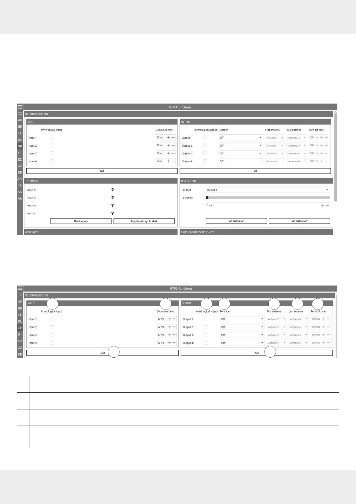
81 of 112
14.6 GPIO Functions
Readers with GPIO functionality1) oer the possibility to set up small controls which trigger the reader, for instance by
means of a light barrier, or which trigger an action at the outputs of the reader by reading specific tags. Such an action
can switch an output to control the flow of goods.
The GPIO tab allows the reader to interact with its environment. The GPIO function tab allows the user to manually read
or switch inputs and outputs of the respective application. For more complex procedures, it is possible to create action
lists which execute a sequence of commands on the reader. This list can then be linked to various inputs.
Fig. 44: GPIO
The GPIO tab is divided into 3 sections,
IO Configuration
, consisting of
Input
and
Output
,
Test Input
and
Test Output
,
Action List
and
Assign Input to Action List
which are described in the following chapters.
14.6.1 IO Configuration
2
8
1 3 4 5 6 7
9
Fig. 45: GPIO: IO Configuration
①
Invert logical
input
negates the electrical input signal and uses this state for processing in the reader; if the param-
eter is not checked, the signal is used
②
Debounce time
assigns a debounce time in milliseconds to each channel depending on the sensor being used
(mechanical or electrical switch)
③
Invert logical
output
negates the electrical output signal
④
Function
selects between the functions described in
Selecting Functions, p.79
⑤
First antenna
the first antenna for the selected function
1) All Generation 3 readers have GPIO.
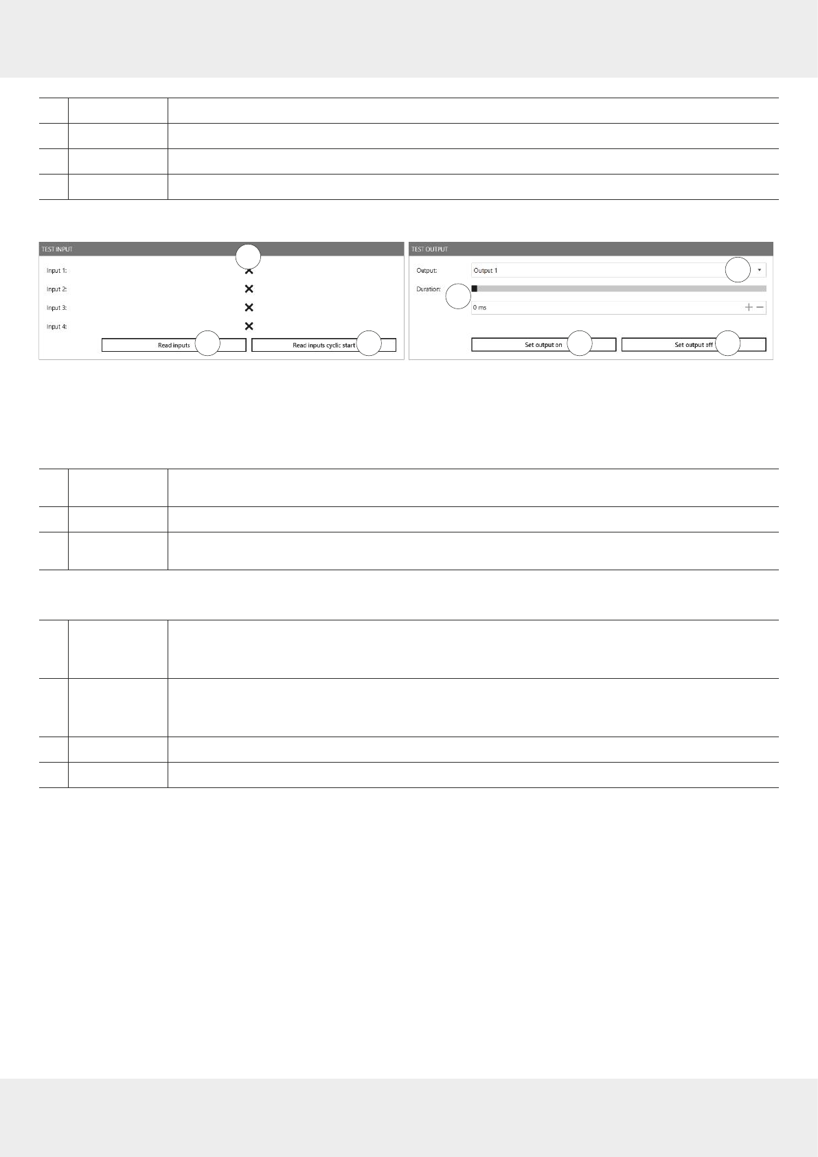
82 of 112
Operating the Reader Using the ReaderStart Software
⑥
Last antenna
the last antenna for the selected function
⑦
Turn-o time
sets the time for how long the output is on for the
Tag found
and
Tag operation successful
function
⑧
Get
reads the current IO configuration settings
⑨
Set
sets the output settings
14.6.2 Test Input and Output
2 3
1
4
5
6 7
Fig. 46: GPIO: Test Input and Test Output
Test Input
Each input channel has two configuration parameters available:
①
Input 1
–
4
shows logical input 1–4; will only be shown if
Invert logical input
for the respective input has been
checked at
IO Configuration
(① in
Fig. 45,p.81
)
②
Read inputs
reads the inputs once
③
Read inputs
cyclic start/stop
reads the inputs in a loop/stops the reading
Test Output
④
Output
selects output 1–4 by means of the drop-down menu
►In order to use this function, select the
Protocol access
function for the respective output (see
IO
Configuration, p.81
and
Selecting Functions, p.79
).
⑤
Duration
sets time in ms after which the output automatically returns to its idle mode either by moving the
bar or by entering the value
If the duration is set to its maximum value (65535), the output is permanently on.
⑥
Set output on
switches on the output
⑦
Set output o
switches o the output
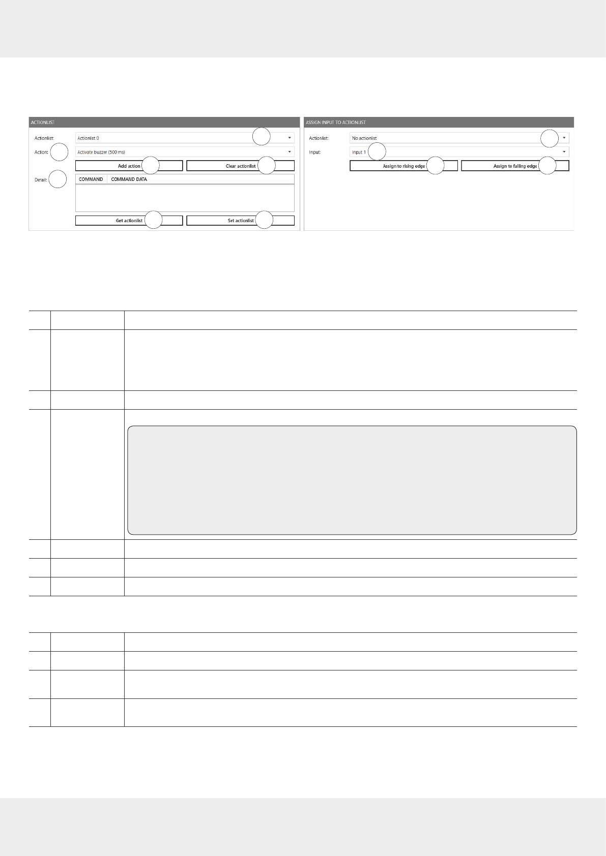
83 of 112
14.6.3 Action List and Assign Input to Action List
To automate the processes, it is possible to store command sequences on the reader in the form of action lists. These
are triggered by a change of edge at the selected input.
23
1
4
5
6 7
8
910 11
Fig. 47: GPIO: Action List and Assign Input to Action List
Action List
Each input channel has two configuration parameters available:
①
Action list
selects an action list (0–127) from the drop-down menu to save the action in
②
Action
selects an action from the drop-down menu, e.g.
Activate buzzer (500 ms), SyncGetEPCs, ASyncGetEPCs,
ASyncStopCommand
; see also
Adding Actions to the Programme, p.84
►To see the commands contained in the current action list, type in %userprofile%\Documents\KATH-
REIN Solutions GmbH\ReaderStart v3 into the Windows search field.
③
Add action
adds action; the action is shown under
Details
(⑤)
④
Clear action list
deletes actions; no actions are seen under
Details
(⑤)
Tip To remove only one action from the list:
1. Select an action from the list shown under
Details.
1. Right-click on the selected action.
➯The pop-up message
Remove entry
appears.
2. Click on
Remove entry
to delete the action.
➯The action is deleted from the list.
⑤
Details
shows added actions in the chronological order as they have been selected
⑥
Get action list
shows the current action list
⑦
Set action list
saves the set action list (flashes blue after having added an action to the
Details
(⑤)
Assign Input to Action List
⑧
Action list
selects an action list (0–127) from the drop-down menu to assign to the input in (⑨)
⑨
Input
assigns the action list to input 1–4 from the drop-down menu
⑩
Assign to rising
edge
assigns the action list to the rising edge
⑪
Assign to falling
edge
assigns the action list to the falling edge
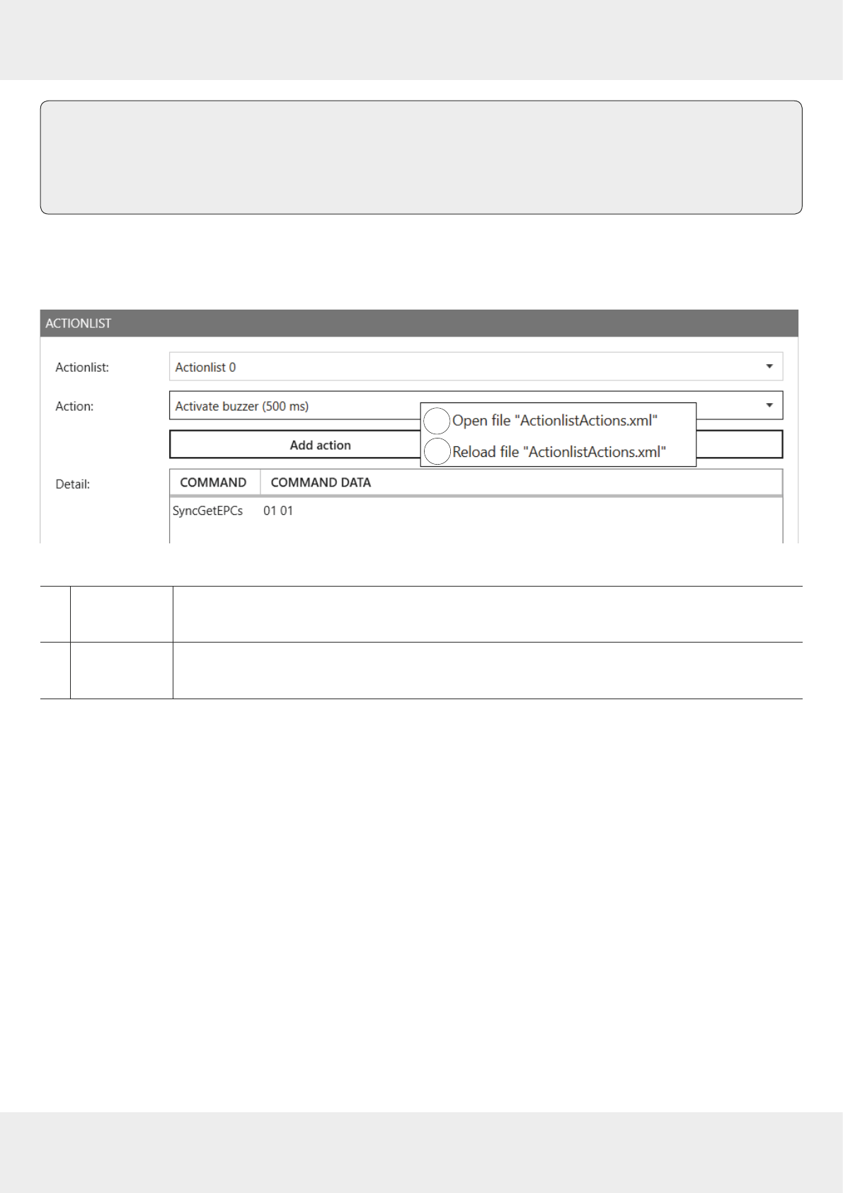
84 of 112
Operating the Reader Using the ReaderStart Software
Tip ►If you would like to assign the action list to both the rising and the falling edge, click
Assign to rising edge
and then
Assign to falling edge
.
To cancel the assignment:
►Restart/reset the reader or select
No action list
under
Action list
(⑧).
Adding Actions to the Programme
The action lists consist of a sequence of individual actions which can be loaded in the form of an XML file in the
Action
context menu:
2
1
Fig. 48: GPIO: action list, action context menu
①
Open file
"ActionlistAc-
tions.xml"
opens the actions list in the XML format in a text editor
②
Reload file
"ActionlistAc-
tions.xml"
reloads the action list; it is necessary to reload the action list after a new action has been added
to the XML file containing the actions or some changes have been made in it
The ReaderStart creates a directory in which the system variables are stored in the folder %userprofile%\Documents\KATH-
REIN Solutions GmbH\ReaderStart v3. It is possible to edit the ActionlistActions.xml file manually using a text editor.
►To see the individual actions, refer to the
Configuration Protocol
.
The approximately 150 reader commands with corresponding variance of the parameters do not allow for a uniform list.
A selection of all options is extensive. Therefore, it is recommended to only list commands required in the application.
The following example demonstrates the syntax of the actions:
<ActionlistActions>
<!--Activate buzzer for 500 ms, CommandID: 0x0045, Parameter: 0x01F4-->
<Action>
<Description>Activate buzzer (500 ms)</Description>
<CommandID>0045</CommandID>
<!--LSB first-->
<Parameter>F4</Parameter>
<Parameter>01</Parameter>
</Action>
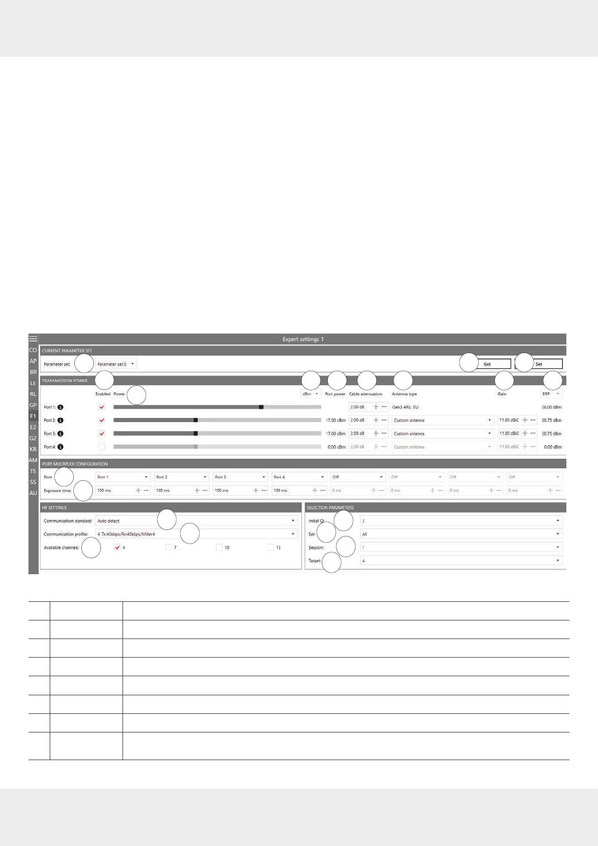
85 of 112
<!--Get EPCs, CommandID: 0x0101-->
<Action>
<Description>Get EPCs</Description>
<CommandID>0101</CommandID>
<!--LSB first-->
</Action>
</ActionlistActions>
The example above shows the
Activate buzzer 500 ms
and
Get EPCs
actions.
14.7 Expert Settings 1
The ReaderStart software is a powerful tool for the reader configuration. It allows the reader to be customised to any
application. The
Expert settings 1
and
2
allow the reader's RF interface and communications profile to be optimised to the
tag so that the reader is optimally customised to the application.
There are eight parameter sets available for saving the reader configuration. It is possible to save all settings for the
transmission power, the antenna multiplex configuration, the RF settings and the air interface parameters.
Other parameters can be changed in
Expert settings 2
.
►For more information about the individual parameters, refer to
Reader Configuration Manual for Kathrein RFID UHF Readers
.
2 3
1456 7 8 9 10 11
12
13
14 15
16
17
1819
20
Fig. 49: Expert settings 1
①
Parameter Set
selects a parameter set
②
Get
reads the current settings of the selected parameter set in the system
③
Set
sets the parameters
④
Enabled
activates/deactivates the possibility to make changes in the port
⑤
Power
changes the power on the port (ERP)
⑥
dBm/W
switches between
dBm
and
W
⑦
Port power
shows the selected power on the port
⑧
Cable
attenuation
selects cable attenuation in the range between 0 and 63.75 dB

86 of 112
Operating the Reader Using the ReaderStart Software
⑨
Antenna type
selects the antenna type between pre-defined and custom antennas
If the pre-defined antenna is selected, the programme sets the antenna gain to the maximum
value permitted for this antenna. If
Custom antenna
is selected, it is possible to freely set the gain
and power.
⑩
Gain
selects the antenna gain between –32.00 dBiC and 31.75 dBiC
⑪
ERP/EIRP
switches between
ERP
and
EIRP
⑫
Port
selects the antenna port or deactivates it
If the antenna is not activated, the system proceeds to the next antenna in the
Port Multiplex
Configuration
.
►For more details, refer to the Chapter MultiplexingAntennaport1...8 in the
Reader Configuration Manual
.
⑬
Exposure time
specifies the exposure time on the antenna; only used for asynchronous operation
►For more details, refer to the Chapter MultiplexingExposureTime1...8 in the
Reader Configuration Manual
.
⑭
Communication
Standard
selects a country-specific communication standard; the device version determines which commu-
nication standard is permitted
⑮
Communication
Profile
selects the profile for the data rate and read reliability
This option allows the technician to directly influence the performance of the reader and the spec-
trum of the signal. The profile names contain basic orientation on the transmission and reception
data rates.
⑯
Available
channels
(only avail-
able for
ETSI-readers)
selects the channel for the reader to use
Depending on the region, the reader transmits in the frequency range 865–868 MHz for Europe or
902–928 MHz for USA/Canada.
In Europe, the number of channels to be used can be limited. For this reason, it is necessary to
check the related check box for each channel the reader is to use. This way, it is possible to avoid
using specific channels on which there is interference.
⑰
Initial Q
reflects the number of tags expected in the field; see also Chapter
InitialQ in
Reader Configuration Manual
⑱
Sel
specifies whether other parameters are of interest for an inventory of the tag population or not;
see also Chapter QuerySel in
Configuration Manual for Kathrein RFID UHF Readers
⑲
Session
sets which session the reader is to work with; see also Chapter Sessions in
Reader Configuration
Manual
⑳
Target
specifies which tags in the population should take part in the inventory; see also Chapter Que-
ryTarget in
Configuration Manual for Kathrein RFID UHF Readers
To operate the reader in accordance with the related national standards, it is necessary to take into account
the antenna gain and the cable attenuation in the transmission power setting.
►Do not exceed the permitted transmission power. Failure to observe this instruction can result in
non-compliant operation of the reader leading the termination of the type approval.

87 of 112
14.7.1 Port Power
In Europe, the radiated power is limited in accordance with ETSI 302208 to 2W ERP. In the FCC/IC region, max. 1W
connected RF power applies with an antenna gain of 6 dBi. If the antenna gain is greater than 6dBi, it is necessary to
reduce the RF power accordingly. While the European standard refers to a half-wave dipole, FCC part 15/RSS 210 refers
to an isotropic radiator.
To set the port power, it is necessary to include the length-dependent cable attenuation and the antenna gain into the
calculation of the port power. An example for the calculation of the port power for Europe and FCC/IC is given below.
The following applies to the European approval region:
Pport = PERP + Dcable – GHW,
where Pport is the port power of the reader in dBm; PERP is the port power based on a half-wave dipole in dBm; Dcable is the
cable attenuation in dB; GHW is the antenna gain based on a half-wave dipole.
The cable attenuation is the length-dependent attenuation of the cable at the related frequency:
Dcable = l*DdB/m,
where Dcable is the cable attenuation in dB; I is the length in m; DdB/m is the attenuation in dB/m at frequency.
The antenna gain is stated in various dierent units. These units include dBi and dBic. The units dBi and dBic refer to an
isotropic (spherical) radiator, where dBic refers to a circularly polarised isotropic radiator and dBi to a linearly polarised
isotropic radiator.
In the European approval area, the radiated power must not exceed 2W ERP. This figure refers to a half-wave dipole. The
relationship shown below exists between an isotropic radiator (dBi) and a half-wave dipole.
GHW = Gisot – 2.14dB,
where GHW is gain-based on a half-wave dipole and Gisot is gain-based on an isotropic radiator in dBi
If the gain of the antenna is referred to the polarisation of a circular isotropic antenna (dBic), the linear gain of the
antenna is 3dB lower. As a result ,the port power can be increased by 3dB.
GHW = Gisot – 2.14dB – 3dB,
where GHW is gain-based on a half-wave dipole and Gisot is gain-based on an isotropic radiator in dBi
In the FCC/IC approval region, the RF power connected at the antenna input must not exceed 1W. If the gain of the
antenna is higher than 6dBi, it is necessary to reduce the RF power correspondingly. The reader's port power is then:
Pport = Pcond + DKabel with Pcond ≤ 1W and Gisot ≤ 6dB,
where Pport is the port power of the reader in dBm; Pcond is the power on antenna output in dBm; Dcable is the cable atten-
uation in dBm; GHW is the antenna gain in dBi.
If the antenna gain is stated in dBic, the reader's transmission power can be increased by 3dB.
The port power for the European variant can be set in 0.25-dB steps from 6dBm to 33dBm.
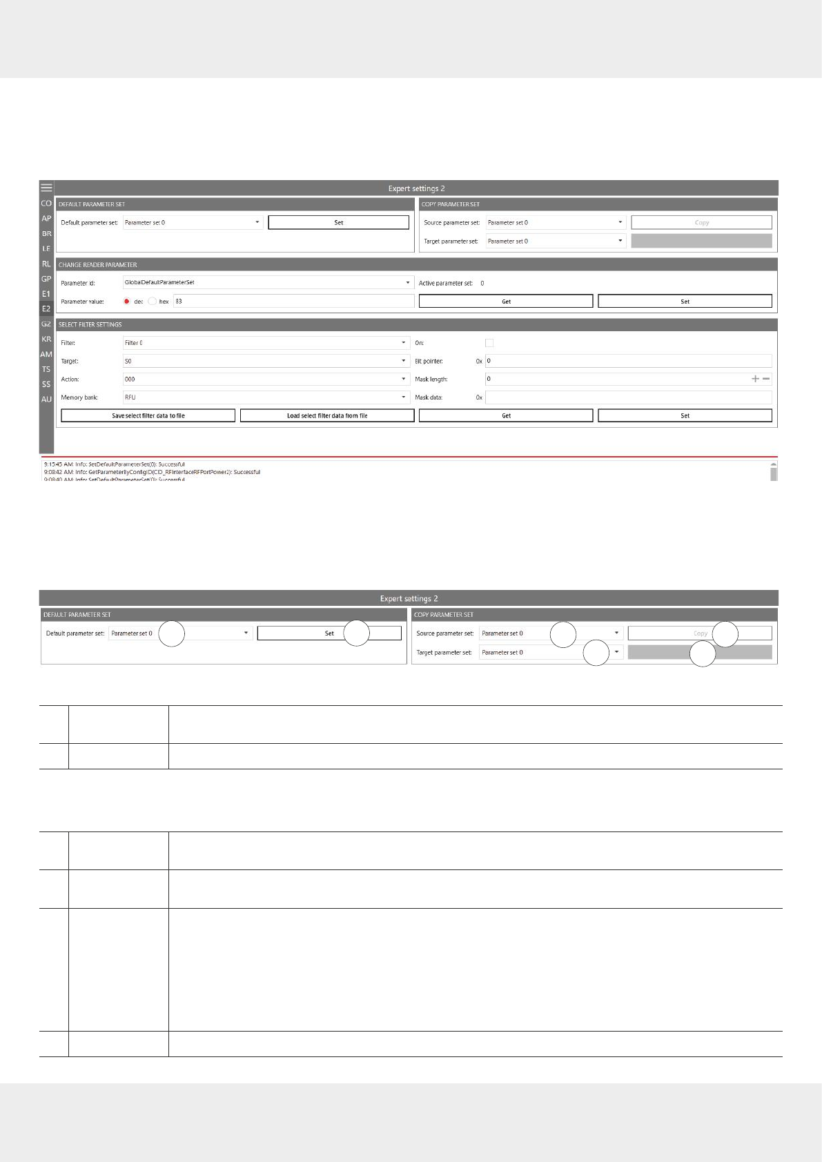
88 of 112
Operating the Reader Using the ReaderStart Software
14.8 Expert Settings 2
The Expert settings 2 tab is divided into four sections for further configuration of the reader. In this tab, it is possible, for
example, to change the default parameter set, copy one parameter set into another, read reader parameters to deter-
mine their ID and configure
Select Filter Settings
.
Fig. 50: Expert settings 2
14.8.1 Default Parameter Set
The
Default parameter set
allows configuration of the parameter set that is loaded from the Flash into the RAM when the
reader is started.
23
1
4
5
6
Fig. 51: Expert settings 2: default parameter set and copy parameter set
①
Default Param-
eter Set
selects a default parameter set
②
Set
sets the selected default parameter set in the reader
14.8.2 Copy Parameter Set
The
Copy parameter set
allows one parameter set to be copied into another.
③
Source param-
eter set
selects the parameter set to be copied
④
Target parameter
set
selects the parameter set into which the source parameter set is to be copied
⑤
Copy
copies the parameter set
►Click
Copy
.
➯On successful completion of the copy operation, the
Copy
button briefly glows green and a
corresponding message is displayed in the status field.
➯If there is an error, the
Copy
button glows red, an error pop-up message appears and a
warning is shown in the status field.
⑥shows the progress of the copying process
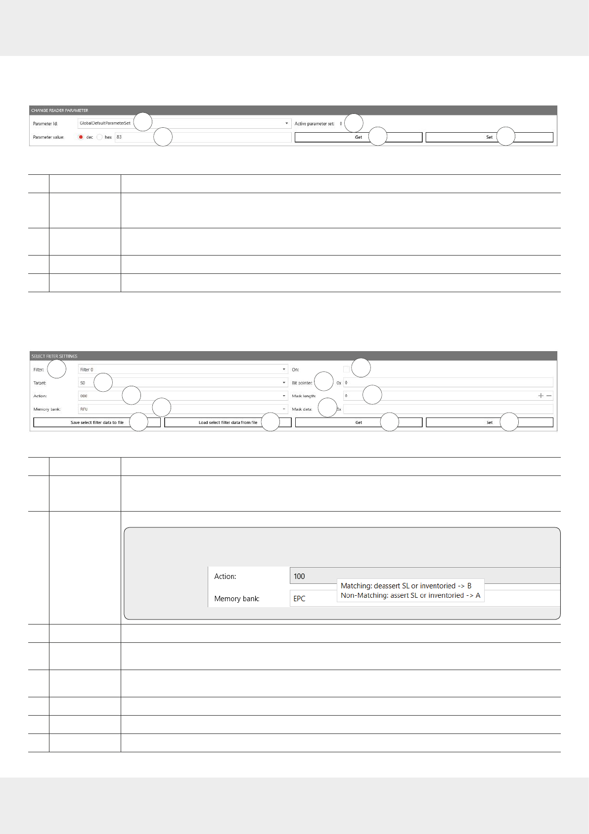
89 of 112
14.8.3 Change Reader Parameter
Change reader parameter
allows to change all reader settings using their respective configuration IDs.
46
1
24 5
3
Fig. 52: Expert settings 2: change reader parameter
①
Parameter ID
selects the parameter ID
②
Parameter value
shows or sets the parameter value
The value is either decimal or hexadecimal, it is possible to switch between
dec
and
hex
.
③
Active parameter
set
shows the current active parameter set
④
Get
reads the value of the current parameter set of the reader and shows it at ②
⑤
Set
writes the parameter value (②) into the selected parameter ID (①)
14.8.4 Select Filter Settings
By means of these settings, it is possible to filter certain tags, e.g. to only read tags with the defined data in the respec-
tive memory banks. It is possible to set up to 32 filters.
7
89
10 11 12
24 5
1234
5 6
Fig. 53: Expert settings 2: select filter settings
①
Filter
selects a filter
②
Target
selects the tag target session
►Make sure the target matches the session set in ⑲
Fig. 50,p.88
.
③
Action
selects the action; see also
EPCglobal Gen 2 Specification
(p. 73)
Tip ►To see the description of an action, hover over the
Action
field.
➯The description of the action appears in the tooltip:
④
Memory bank
selects the memory bank (
RFU
/
EPC
/
TID
/
User
)
⑤
Save select filter
data to file
saves the select filter data to file
⑥
Load select filter
data to file
loads the select filter data from file
⑦
On
activates or deactivates the select filter
⑧
Bit pointer
sets from which memory address the filter compares the mask data
⑨
Mask length
sets the mask length (0–255)
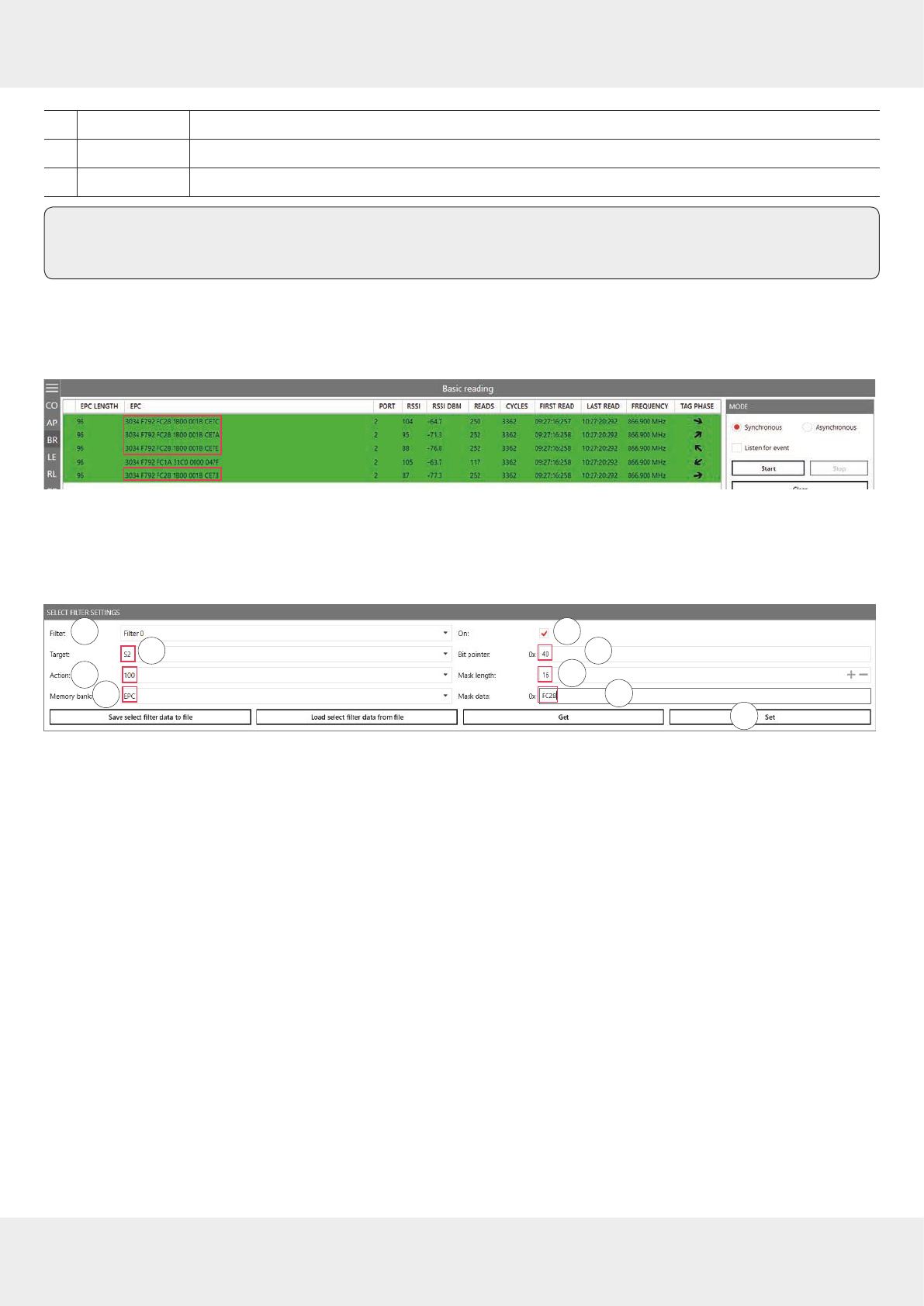
90 of 112
Operating the Reader Using the ReaderStart Software
⑩
Mask data
sets the data to be filtered
⑪
Get
reads the data of the filter selected at ①
⑫
Set
sets the select filter
Tip In Generation 3 readers, select filter data are permanently stored in the reader, e.g. if the select filter has
been activated, it is active after a reader restart.
14.8.5 Applying a Select Filter (Example)
You have the following results of the basic reading but you would like only the tags with the
FC28
in the memory address
to take part in the inventory:
Fig. 54: Basic reading: select filter required
To do so, it is necessary to create a select filter. The advantage of this process is that the filtering takes place already at
the air interface level.
To create the select filter as shown in the figure below:
789
24 5
12
34
56
1. Select the filter you would like to save the filtering settings to under
Filter
(①).
2. Select the target (②). Make sure the target matches the session set in ⑲
Fig. 50,p.88
.
3. Select an action (③). In the example, the action is set to
100
; see also
EPCglobal Gen 2 Specification
.
4. Select the
EPC
memory bank (④).
5. Activate the select filter (⑤).
6. Refer to the
EPCglobal Gen 2 Specification
to check from which bit pointer the filter will search for the value according to
which you would like to filter the tags (
FC28
in the example); see pp. 44–46 in the
EPCglobal Gen 2 Specification V 2.0.
1. In
the example,
FC28
is the third word in the EPC memory bank (bit pointer 0x00 is the CRC, bit pointer 0x10 is the PC,
bit pointer 0x20 is the first EPC word). Therefore,
FC28
corresponds to the bit pointer 0x40.
7. Enter
40
at
Bit pointer
(⑥).
8. Enter the mask length at ⑦. In the example,
FC28
is one word, therefore, the value is
16
.
9. Enter the value (
FC28
) at ⑧.
10. Click
Set
(⑨).
11. Go to
Expert settings 1
.
12. In Selection Parameters, set the value at target to
B
; see also
EPCglobal Gen 2 Specification
.
13. Start the reading in the
Basic reading
tab:
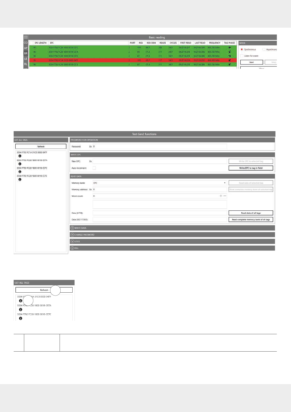
91 of 112
➯The reader only reads the tags with the filtered value (marked green). The tag without the filtered value is not
read (marked red).
14.9 Test Gen 2 Functions
This tab makes it possible to access individual tag functions. In addition to the functionality in accordance with the EPC
Gen2 standard, it is possible, for example, to read and write tags as well as set and change tag passwords.
The user interface consists of the fields
Get all Tags
,
Password for Operation
,
Write EPC
,
Read data
,
Write data
,
Change Password
,
Lock
and
Kill
that are described in the following chapters.
Fig. 55: Test Gen2 functions
14.9.1 Get All Tags
1
2
Fig. 56: Test Gen2 functions: Get all EPCs
①
Refresh
updates the tags read in the field
►For EPC-specific operations, click on a tag to select it from the list.
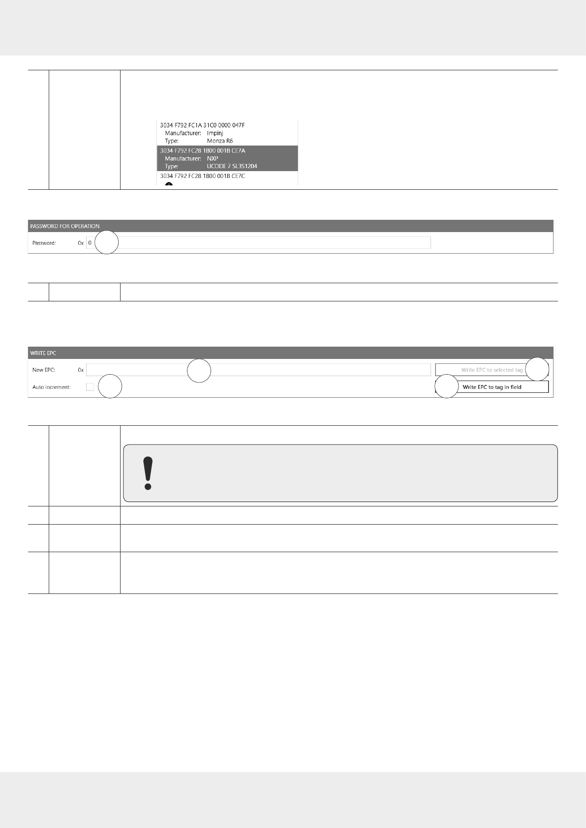
92 of 112
Operating the Reader Using the ReaderStart Software
②Info
shows the information about the tag manufacturer and the chip type
►Click on the information symbol.
➯The information about the tag is shown:
14.9.2 Password for Operation
1
Fig. 57: TestGen2: password for operation
①
Password
sets the password for the tag operation in the hexadecimal format
14.9.3 Write EPC
In this tab, it is possible to change the EPC of the tag.
23
4
1
Fig. 58: TestGen2: write EPC
①
New EPC
enters an EPC in the hexadecimal format
Make sure to comply with the maximum EPC length supported by the tag. If the max-
imum length is exceeded, the tag will return an error.
②
Auto increment
activates or deactivates increasing the EPC by one with each successful writing process
③
Write EPC to
selected tag
writes the EPC on the selected tag
④
Write EPC to tag
in field
writes the EPC entered in 1 to a single tag
►When using this command, make sure there is only one tag in the field. Otherwise, an error
message is displayed in the status field.
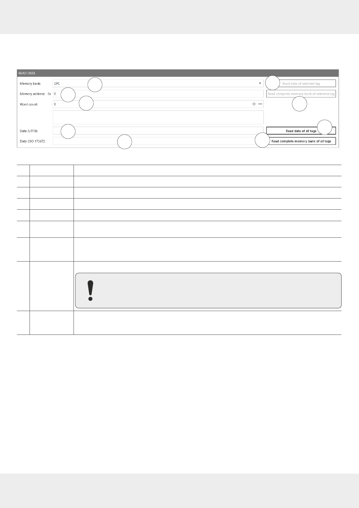
93 of 112
14.9.4 Read Data
This group supplies detailed access to all the data areas of the tag. Access is obtained by entering the selected memory
bank, the address within the memory bank and the number of words.
2
4
6
7
8
9
3
4
1
5
Fig. 59: TestGen2: read data
①
Memory bank
enters the selected memory bank
②
Memory address
enters the address within the memory bank
③
Word count
enters the number of words to read
④
Data (UTF8)
shows the data in the UTF8 format
⑤
Data (ISO 17367)
shows the data in the ISO 17367 format
⑥
Read data of
selected tag
reads data from the selected tag
⑦
Read complete
memory bank of
selected tag
reads the complete memory bank of the selected tag; up to 255 words
⑧
Read data of all
tags
reads data from all tags in the field
If the tags in the field have dierent passwords and are configured dierently, it is nec-
essary to read the data from each tag individually.
⑨
Read complete
memory bank of
all tags
reads the complete memory bank of all tags in the field; up to 255 words
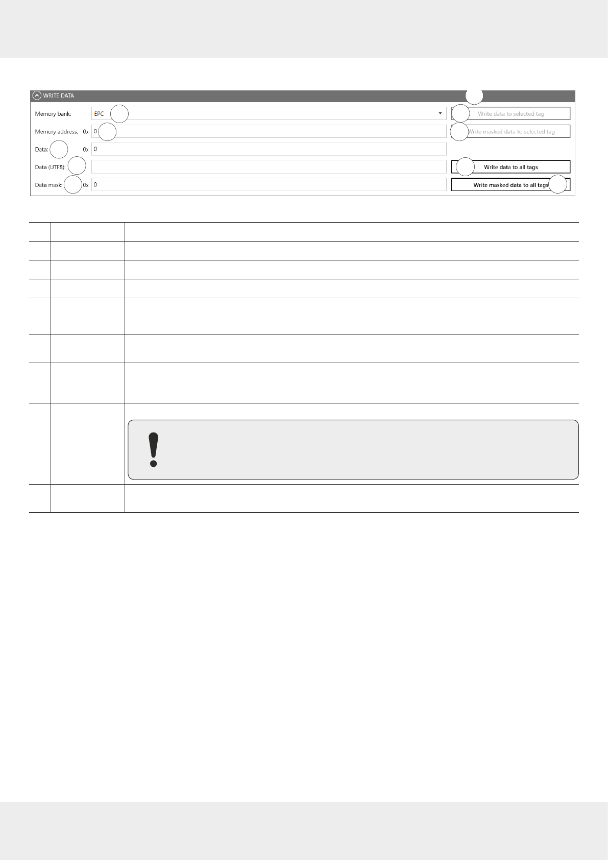
94 of 112
Operating the Reader Using the ReaderStart Software
14.9.5 Write Data
4
6
7
89
2
34
1
5
Fig. 60: TestGen2: write data
①
Memory bank
enters the selected memory bank
②
Memory address
enters the address within the memory bank
③
Data
enters data to write in the hexadecimal format
④
Data (UTF8)
enters data to write in the UTF8 format
⑤
Data mask
enters the data mask
The data mask allows only individual bits on the tag to be changed.
⑥
Write data to
selected tag
writes data to the selected tag in the field
⑦
Write masked
data to selected
tag
writes the masked data to the selected tag
⑧
Write data to all
tags
write data to all tags in the field
►If the data are written to all tags in the field, make sure all the tags have the same
configuration (lock and password).
⑨
Write masked
data to all tags
writes the masked data to the all tags in the field

95 of 112
14.9.6 Change Password
To change the password, enter the current password at ① in
Fig. 57,p.92
. If no password has yet been set, the default
value is 0.
2
4
31
Fig. 61: TestGen2: change password
①
New password
sets the new password in the hexadecimal format for the selected tag
②
New kill
password
sets the new password to deactivate the selected tag
③
Set password on
selected tag
replaces the old password by the new password for the selected tag
④
Set kill password
on selected tag
replaces the old deactivation password by the new deactivation password for the selected tag

96 of 112
Operating the Reader Using the ReaderStart Software
14.9.7 Lock
The
EPC Gen2
standard provides security mechanisms for the tag data areas. This allows individual memory areas and
functionalities of the tags to be provided with a password to protect it against access and/or changes.
Under
Lock
, it is possible to lock the memory banks.
27
9
4
1
3
5
6
Fig. 62: TestGen2: Lock
①
Kill password
specifies how the kill password is accessible
►Select one of the following options from the drop-down menu:
No change
the current setting for the kill password remains unchanged
Accessible
the kill password is readable and writeable from either the open or
secured state
Accessible with permalock
the kill password is permanently readable and writeable from either the
open or secured states and may never be locked
Accessible with password
the kill password is readable and writeable from the secured state but
not from the open state
Not accessible with
permalock
the kill password is not readable or writeable from any state
►For more details, see
EPCGlobal Gen2 Specification
.
②
Access password
specifies how the access password is accessible
►Select an option from the drop-down menu; see the options at ①.
►For more details, see
EPCGlobal Gen2 Specification
.
③
EPC memory
bank
specifies how the EPC memory bank is accessible
►Select one of the following options from the drop-down menu:
No change
the EPC memory remains unchanged
Writeable
the EPC memory bank is writeable from either the open or secured states
Writeable with
permalock
the EPC memory bank is writeable from either the open or secured states
and may never be locked
Writeable with password
the EPC memory bank is writeable from the secured state but not from
the open state
Not writable with
permalock
the EPC memory bank is not writeable from any state
④
TID memory
bank
specifies how the TID memory bank is accessible
►Select an option from the drop-down menu; see the options at ③.
⑤
User memory
bank
specifies how the User memory bank is accessible
►Select an option from the drop-down menu; see the options at ③.
⑥
Lock selected tag
locks the selected tag with the settings from ①−⑤
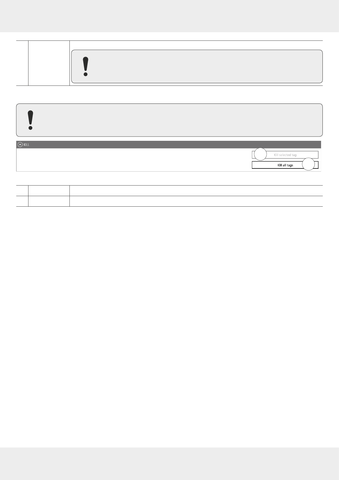
97 of 112
⑦
Lock all tags
locks all the tags with the settings from ①−⑤
►To lock all the tags, make sure that all the tags have the same password.
14.9.8 Kill
►To deactivate a tag, set a deactivation password that is not 0; see ② in
Fig. 61,p.95
.
After a kill command, the tag will be unusable!
2
1
Fig. 63: TestGen2: kill
①
Kill selected tag
executes a kill command on the selected tag
②
Kill all tags
executes a kill command on all tags in the field
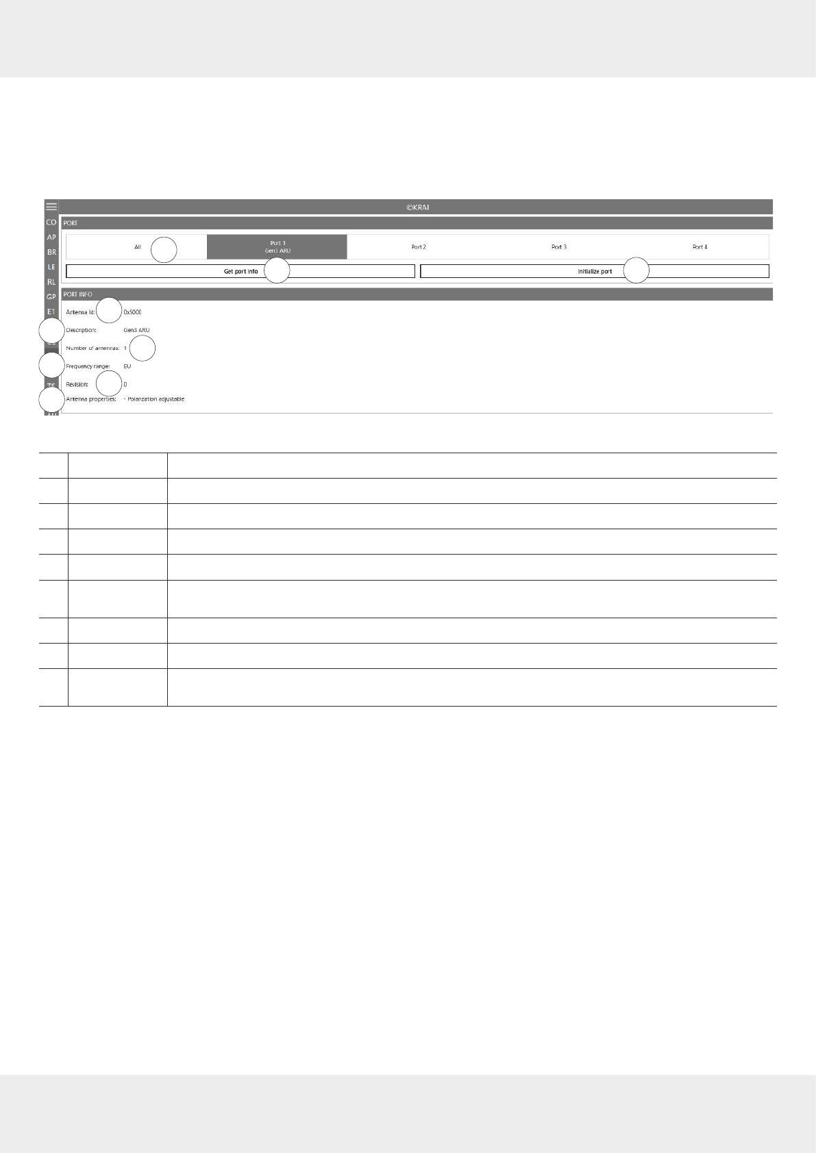
98 of 112
Operating the Reader Using the ReaderStart Software
14.10 @KRAI
This tab allows changing KRAI-specific settings. The
@KRAI
tab is divided into several sections.
Port
and
Port Info
are
always available, other sections depend on the antenna connected to the reader, e.g.
Polarisation
,
Direction
etc.
The Reader recognises the connected antennas at boot up, but it is also possible to manually recognise a single port or
all ports under
Port
.
Port Info
displays the information about the antenna.
2 3
1
4
56
78
9
10
Fig. 64: @KRAI: polarisation
①
All/Port 1
–
4
selects either one or all antennas for
Initialise port
(③)
②
Get port info
retrieves port information for a selected @KRAI antenna
③
Initialise port
runs a query of the antennas on this port/these ports
④
Antenna Id
shows the antenna ID
⑤
Description
shows the description of the antenna
⑥
Number of
antennas
shows the number of the antennas connected to the port
⑦
Frequency range
shows the frequency range the antenna operates in (
Global
/
EU
/
FCC
)
⑧
Revision
shows the hardware version of the antenna
⑨
Antenna
properties
shows antenna properties, e.g.
polarisation adjustable
,
LEDs available
Dierent configuration options are displayed, depending on the types of the connected antennas. The category
Polarisa-
tion
is shown for antennas with polarisation switching, the
Jumper Cable Attenuation
is available for smart shelf antennas,
e.g. SMSH-30-30KRAI,
LED
is shown for @KRAI WIRA 70 and
Direction
for CSB KRAI antennas, e.g. WiRa 30º.
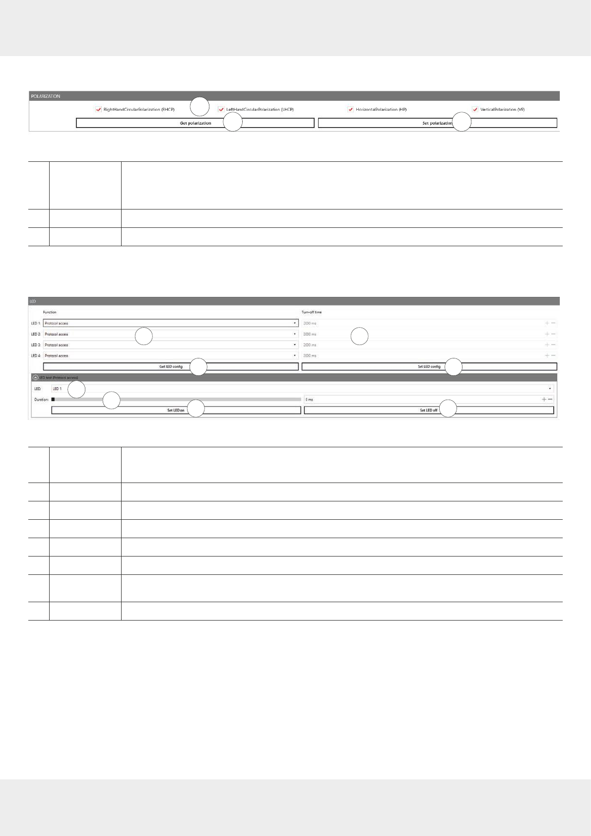
99 of 112
14.10.1 Polarisation
2 3
1
9
Fig. 65: @KRAI: polarisation
①
sets the polarisation of the antenna
If there are several types of polarisation selected at the same time, the antenna configuration
changes after every inventory.
②
Get polarisation
reads the current polarisation information of the antenna
③
Set polarisation
sets the polarisation on the antenna
14.10.2 LED
Depending on the features that are integrated in the antennas, it is possible to control/configure the LEDs.
2
3
1
4
567 8
Fig. 66: @KRAI: LED
①
LED 1
–
4
selects the function of the LED 1–4
►For functions, see Chapter
Selecting Functions, p.79
②
Turn-o time
sets the turn-o time for LED
③
Get LED config
shows the current LED configuration
④
Set LED config
sets the new LED configuration
⑤
LED
selects between LED 1–4
⑥
Duration
sets the duration of how long the LED is on; only if protocol access is selected in ①
⑦
Set LED on
switches the LED on for the duration in milliseconds selected in ⑥; if the duration is set to 65535
ms, the LED is permanently on
⑧
Set LED o
switches o the selected LED
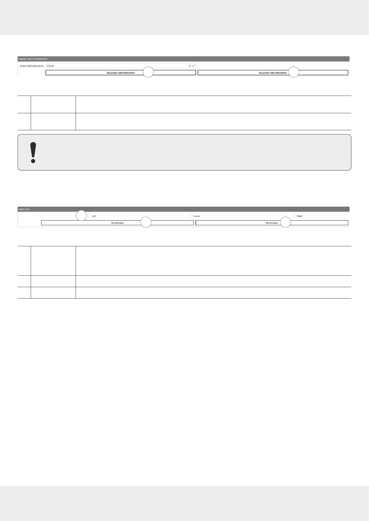
100 of 112
Operating the Reader Using the ReaderStart Software
14.10.3 Jumper Cable Attenuation
21
Fig. 67: @KRAI: jumper cable attenuation
①
Get jumper cable
attenuation
reads the current jumper cable attenuation
②
Set jumper cable
attenuation
sets the jumper cable attenuation
For cascading smart shelf antennas, it is necessary to use cables with the same attenuation (cable length).
Otherwise, the TX power of the antennas that is derived from the jumper cable attenuation is not calculated
correctly.
14.10.4 Direction
2 3
1
Fig. 68: @KRAI: direction
①
Left/Centre/
Right
sets the direction of the antenna
If there are several types of direction selected at the same time, the antenna configuration
changes after every inventory.
②
Get direction
reads the antenna direction(s) currently set in the antenna
③
Set direction
sets the selected direction(s) in the antenna

101 of 112
14.11 AppManager
This chapter gives a short overview of the apps, the requirements to operate them and the installation
instructions.
►For more information on how to operate an app, refer to the user guide for the corresponding app.
14.11.1 Currently Available Apps
AccessManager
Automated vehicle identification (AVI) is one of the key markets that Kathrein Solutions is focusing on. AVI includes free
flow identification, plaza and parking applications. For parking applications, Kathrein provides a specially configured
software for access control called
AccessManager
.
The RRU 4xxx and ARU 3xxx series readers have a built-in industrial controller with Linux operating system. The entire
application can be installed and configured directly on the reader. The system can be operated as an isolated solution
without a network connection or alternatively via remote access over the network for configuration purposes or for data-
base adaptations.
The
AccessManager
application software allows user-guided input and configuration of the transponder data that is to be
captured. No programming knowledge is required in this case.
Flexible and ecient detection (e.g. of vehicles) is assured on the basis of the four digital inputs provided in Kathrein
RFID systems which can be used for activation. A start point can be defined for the application in this way, whereby a
light barrier or inductive ground contact is queried in order to activate the reading process.
Skidata
The Skidata app is a software-based solution that provides simple and easy interface integration of Kathrein RFID
readers with Ethernet in the latest generation of Skidata barrier systems. With the Skidata app, the reader will become
an ocially certified SKIDATA compatible product.
Low Level Reader Protocol
Kathrein RFID readers are available with an optional LLRP (Low Level Reader Protocol) stack installable as an LLRP app.
All readers with an integrated embedded Linux OS can be controlled via LLRP 1.0.1 port 5084 for easier integration. To
specify air interface commands between readers and clients, LLRP is a ratified standard protocol from EPCglobal.
Profinet IO
The Profinet IO app allows the integration of a reader into a Profinet IO environment; the reader acts as an IO device. To
run the app, a valid licence key is needed. Licence keys (either a full licence or a time limited demo licence) are bound to
the specific reader the app is running on. For obtaining a licence key, the hardware key provided by the app is needed.
TagBlower
The TagBlower app can read tags asynchronously and generate messages,when a tag is coming or going. The app pro-
vides a server on a configurable port, where TCP clients can connect to receive those messages. The message format
can be specified by the user by setting a coming and/or going datagram. A datagram consists of normal text and
keywords.
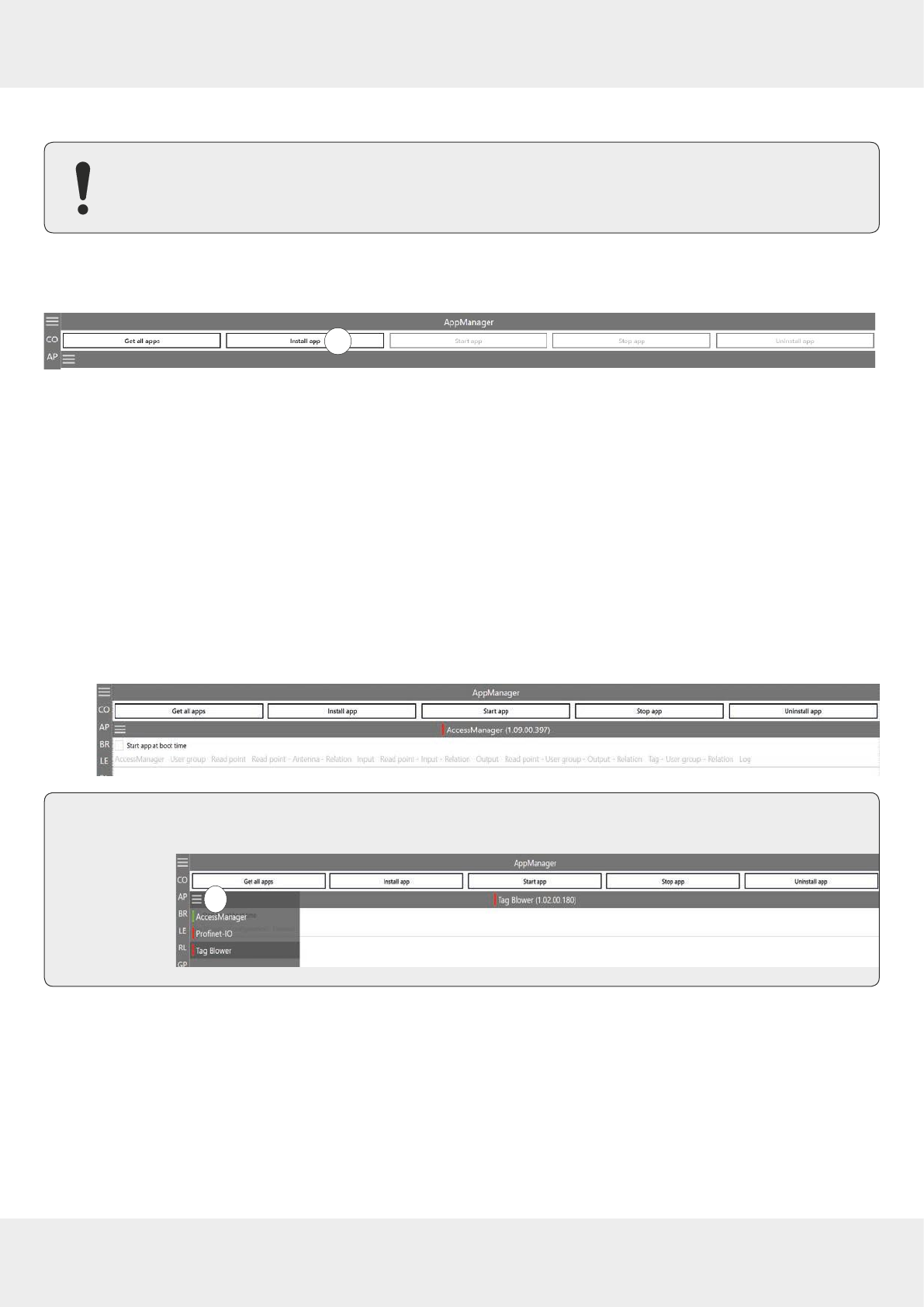
102 of 112
Operating the Reader Using the ReaderStart Software
14.11.2 Installing an App
This chapter describes installing an app shown on the example of
AccessManager
. You can install all other
apps following the instructions described below.
✔ The
ReaderStart
software is installed.
✔ The reader is connected to a PC.
1
Fig. 69: AppManager: installing an app
1. Go to https://www.kathrein-solutions.com/products/software/interface-software/accessmanager.
2. Downoad the app.
3. If the downloaded app is in the zip format, extract a .tar file. Make sure not to extract the .tar file!
4. Start the
ReaderStart
software.
5. Go to the
AppManager
tab.
6. Click on
Install app
(①).
➯A pop-up window to select the file with the app opens.
7. Select the file with the app. Make sure it is the .tar file.
8. Click Open.
➯A pop-up message with the progress bar for the installation process appears for the duration of the installation .
After the app has been successfully installed, the corresponding message is displayed in the status field and the
app interface is shown in the
AppManager
tab:
Tip ►To see all the installed apps, click the menu symbol at (①).
➯The installed apps are displayed:
1
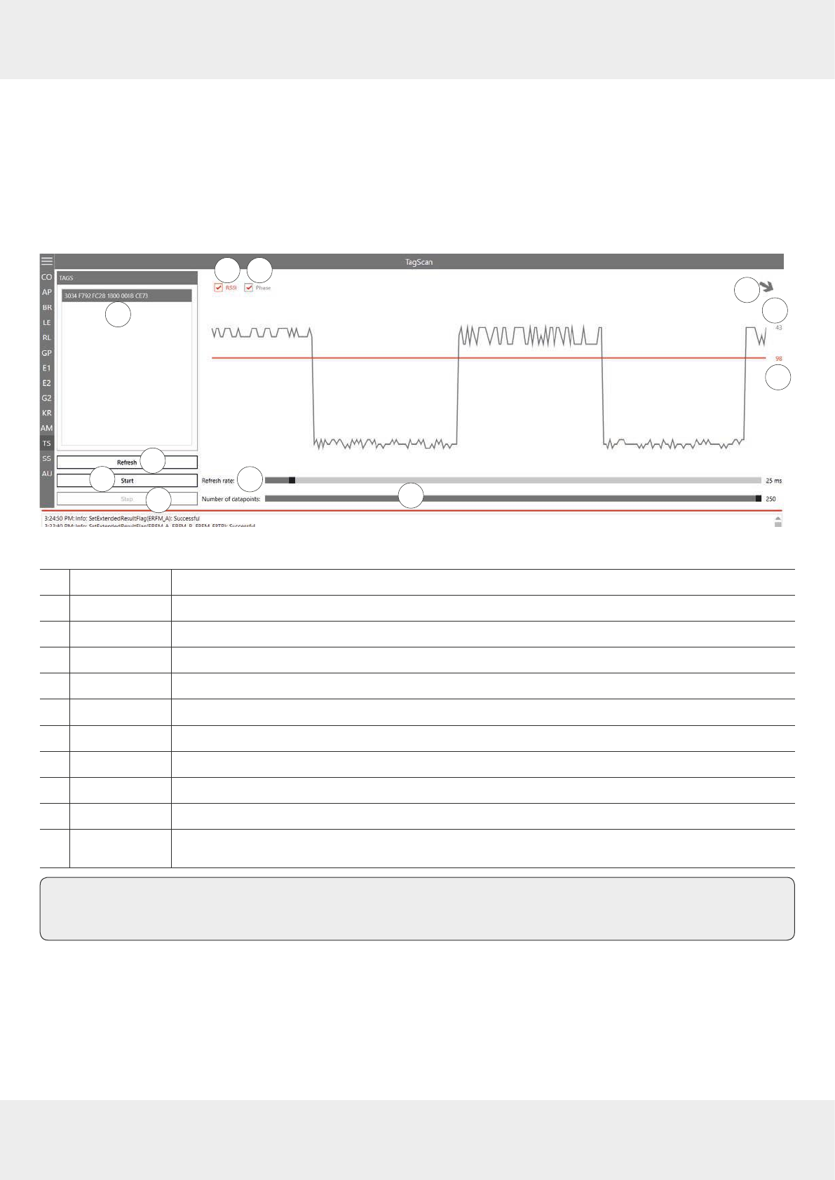
103 of 112
14.12 TagScan
To represent the relationship between the tag phase and the RSSI value, it is possible to plot both values by means of
the TagScan.
✔ There is only one tag in the field or a tag has been selected.
►Click
Start
to activate the TagScan.
➯The phase shifts are seen in the frequency switching. The RSSI value does not change because the transponder
(tag) is not moved.
2
3
1
4
5 6 78
9
10 11
Fig. 70: TagScan: phase shift (due to the channel change), transponder is not moved
①
Tags
shows the number of the tags present in the antenna field
②
Refresh
scans tags in the antenna field anew
③
Start
starts TagScan
④
Stop
stops TagScan
⑤
RSSI
activates/deactivates the presentation of the RSSI value in the graph
⑥
Phase
activates/deactivates the presentation of the phase in the graph
⑦shows the phase in form of the rotating arrow
⑧shows the current value of the phase
⑨shows the current RSSI value
⑩
Refresh rate
sets the interval between the commands
⑪
Number of data
points
sets the number of data points in the graph
Tip ►To eliminate the phase shifts, select only one transmission frequency under
Expert settings 1
; see
Expert Set-
tings 1, p.85
.
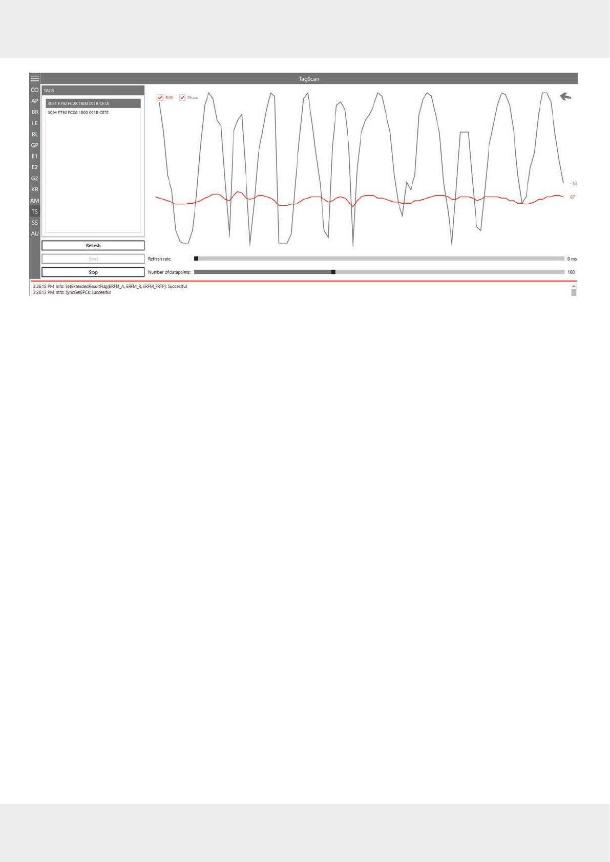
104 of 112
Operating the Reader Using the ReaderStart Software
Fig. 71: TagScan: phase shift, transponder is moved
Transponder movement is indicated by the amplitude of the phase. The RSSI value changes in small steps. The direction
of the movement is indicated by means of the rotating pointer.
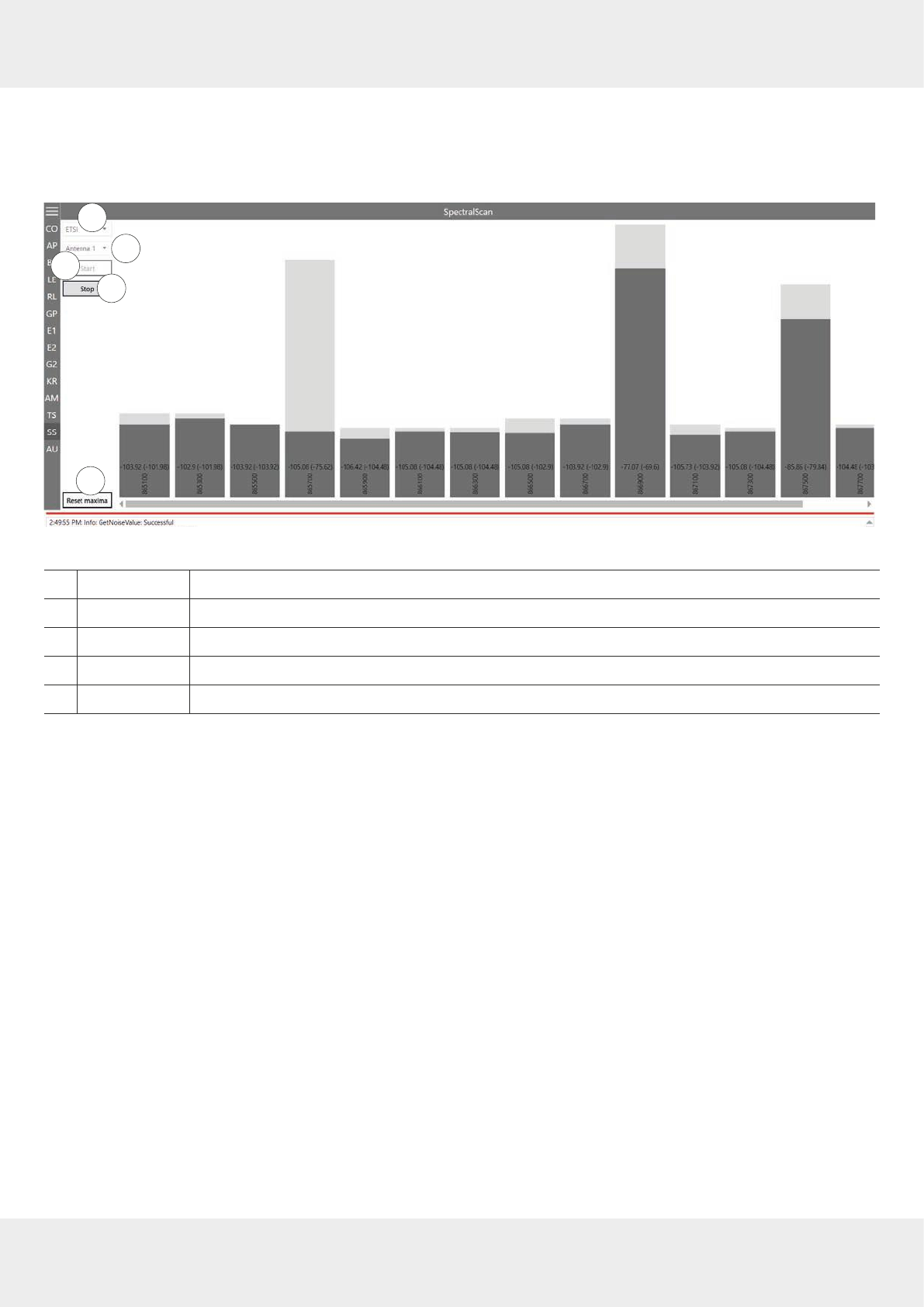
105 of 112
14.13 Spectral Scan
It may happen that the RFID transmission to or from the transponder is disturbed by frequency interfering.
SpectralScan
shows a qualitative frequency spectrum. Due to the fact that it is received by means of the connected RFID antenna, the
frequency assignment on location is made visible.
1
4
2
3
5
Fig. 72: SpectralScan
①
ETSI
selects the frequency area
②
Antenna 1
–
n
selects an antenna from the drop-down menu
③
Start
starts SpectralScan
④
Stop
stops SpectralScan
⑤
Reset maxima
resets maxima
If there is more than one reader, spectral scan shows which channels might be occupied by other readers. In
Fig. 71,p.104,
the channels 4, 10 and 13 are occupied by other readers. If the user is not satisfied with the reading results
and the interferences keep occurring, it is possible to deactivate channels on which the interference occurs (4, 10 and
13) and only activate the channel that is free (7) to achieve better reading results, see ⑯ in
Fig. 49,p.85
.
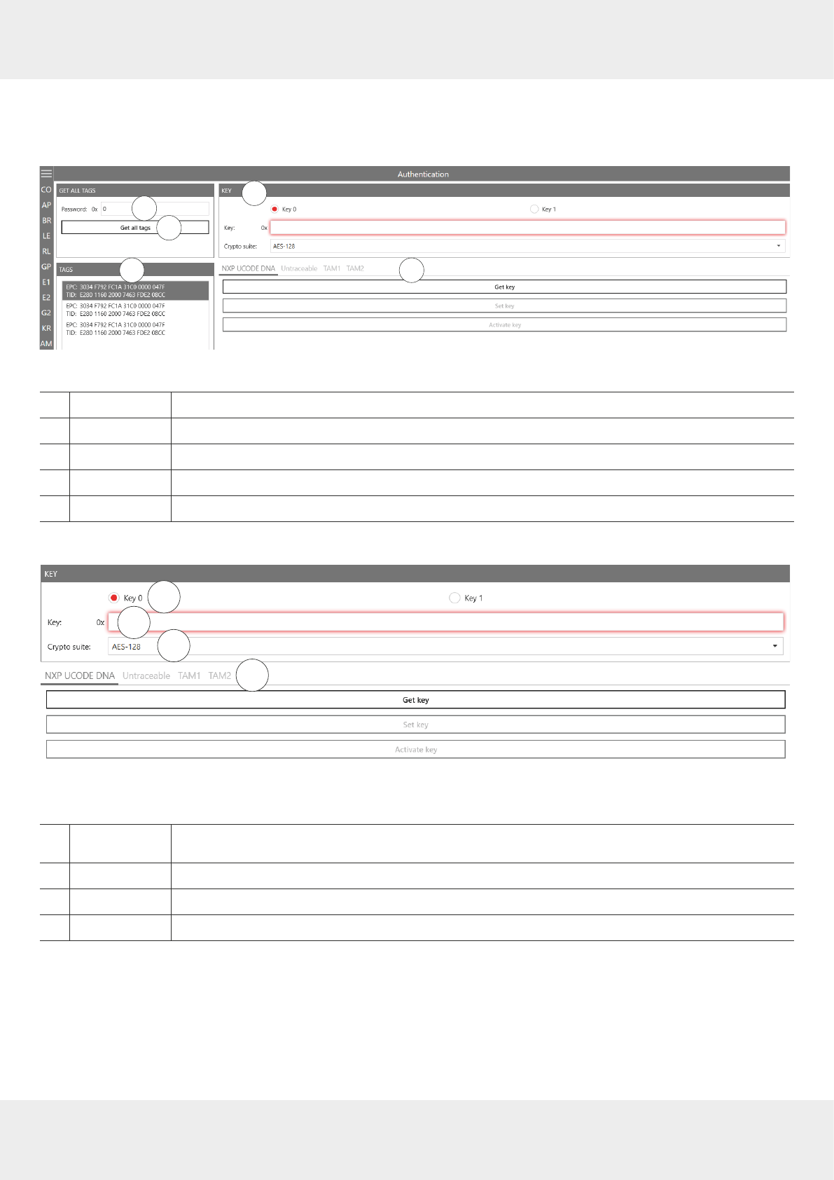
106 of 112
Operating the Reader Using the ReaderStart Software
14.14 Authentication
Using this function, it is possible to authenticate a tag.
The Authentication tab consists of 4 areas,
Get All Tags
,
Tags
,
Key
and functions that are described below.
14
2
3 5
Fig. 73: Authentication
①
Password
enters the access password; see
Password for Operation, p.92
②
Get all tags
reads all the tags in the antenna field
③
Tags
shows all the detected tags
④
Key
see
Key, p.106
; necessary for
TAM1
and
TAM2
⑤
Functions
see
Functions, p.107
14.14.1 Key
1
4
23
Fig. 74: Authentication: Key
①
Key 0/Key 1
selects a key for the authentication (
Key 0
is only used for
TAM1
,
Key 1
is used for both
TAM1
and
TAM2
)
②
Key
enters the key selected in ①
③
Crypto suite
selects the crypto suite
④see
Functions, p.107
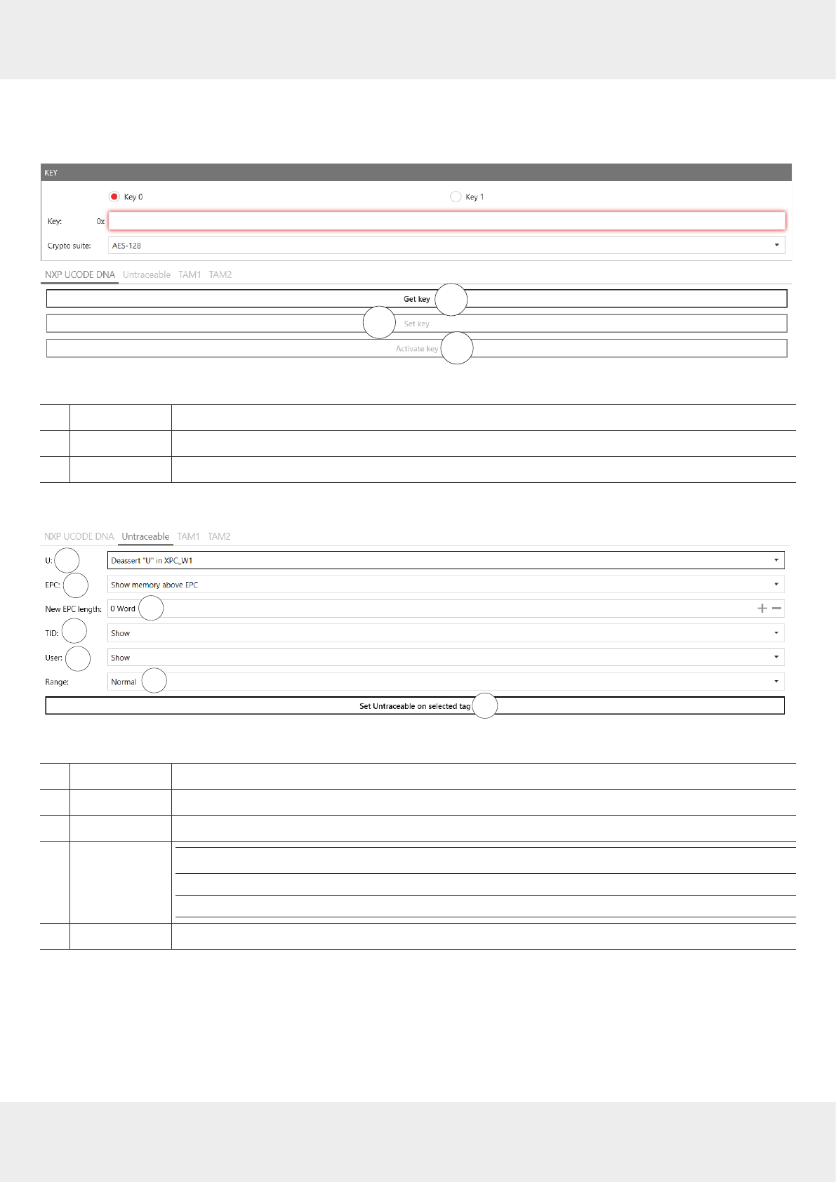
107 of 112
14.14.2 Functions
NXP UCODE DNA
1
2
3
Fig. 75: Authentication: NXP UCODE DNA
①
Get key
reads key 0 or key 1 currently set in the selected tag; only if the key has not been activated
②
Set key
sets key 0 or key 1 on the selected tag
③
Activate key
activates key 0 or key 1 on the selected tag
Untraceable
1
7
4
23
56
Fig. 76: Authentication: untraceable
①
U:
asserts or deasserts U in XPC_W1; see
EPCglobal Gen2 Specification, p. 106
②
EPC
shows or hides memory above the visible EPC
③
New EPC length
sets new EPC length in words
④
TID
Show
shows the complete TID
Truncated
shows the first two words in case of E2 and only one word in case of E1
Hide
hides the complete TID
⑤
User
shows or hides the user memory bank

108 of 112
Operating the Reader Using the ReaderStart Software
⑥
Range
selects a range
Normal
the tag operates in the normal range
Toggle temporarily
The tag temporarily toggles between normal and reduced operating range
but reverts to its prior persisting operating range when the tag loses
power
Reduced
the tag operates in the reduced operating range
⑦
Set Untraceable
on selected tag
sets settings 1–6 on the selected tag
TAM1
TAM1 is used to check whether the selected tag is authentic.
✔ The tag has at least one activated key,
Key 0
or
Key 1
.
1
4
2
3
5
Fig. 77: Authentication: key (TAM1)
Key
see
Key, p.106
①
Authenticate
selected tag
the reader sends the authenticate command to the selected tag; a pop-up message appears
whether the authentication was successful or failed.
②
RRU
→
Tag
shows the random number sent to the tag by the reader
③
RRU
←
Tag
shows the encrypted random number sent to the reader from the tag
④
AES Decryption
shows the data decrypted from ③ by means of the key entered at ② in
Authentication: Key, p.106
; in
the example above, this data contains the random number shown in ②
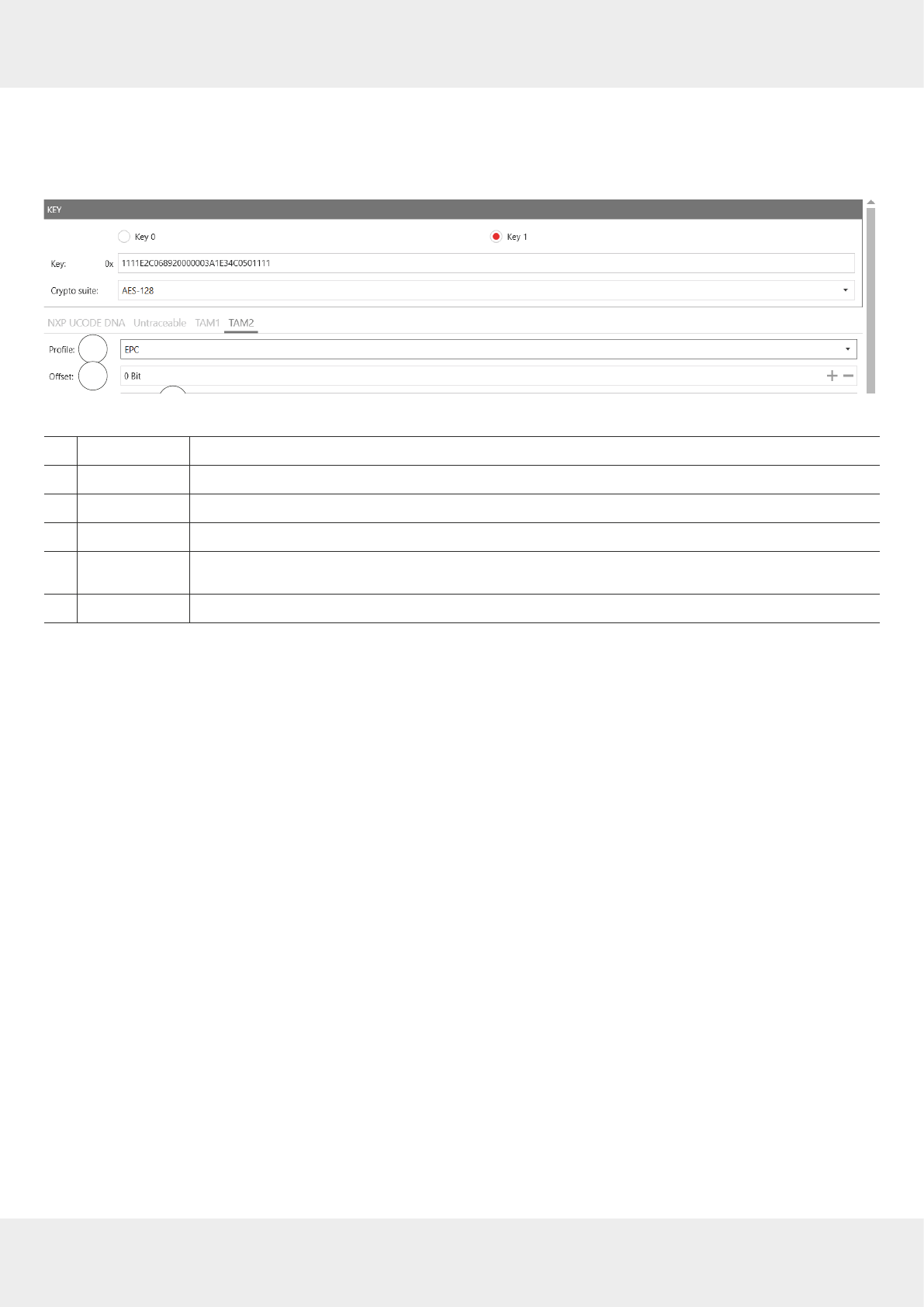
109 of 112
TAM2
TAM2 is used to read the data of the selected tag.
✔
Key 1
has been activated.
1
7
4
2
3
5
6
Fig. 78: Authentication: key (TAM2)
①
Profile
selects a profile the data of which is shown
②
Oset
sets the oset for ⑤
③
Block count
sets how many bits rare to be read
④
Protection mode
selects the protection mode for the TAM2 authentication operation
⑤
Read data of
selected tag
reads the data of the selected tag provided the correct key 1 has been entered at
Key
⑥
Data
shows data read in ⑤


111 of 112
16 Waste Disposal
Electronic equipment is not domestic waste – in accordance with directive 2002/96/EC OF THE EUROPEAN
PARLIAMENT AND THE COUNCIL dated 27th January 2003 concerning used electrical and electronic appli-
ances, it must be disposed of properly. At the end of its service life, take this unit for disposal at a desig-
nated public collection point.

V 1.03/0118/GB | Subject to change.
www.kathrein-solutions.com | iot-info@kathrein-solutions.com
Kathrein Solutions GmbH, Kronstaudener Weg 1, 83071 Stephanskirchen, Germany, Phone +49 8036 90831 20, Fax +49 8036 90831 69
Electronic equipment is not domestic waste – in accordance with directive 2002/96/EC OF THE
EUROPEAN PARLIAMENT AND THE COUNCIL dated 27th January 2003 concerning used elec-
trical and electronic appliances, it must be disposed of properly. At the end of its service life,
take this unit for disposal at a designated public collection point.