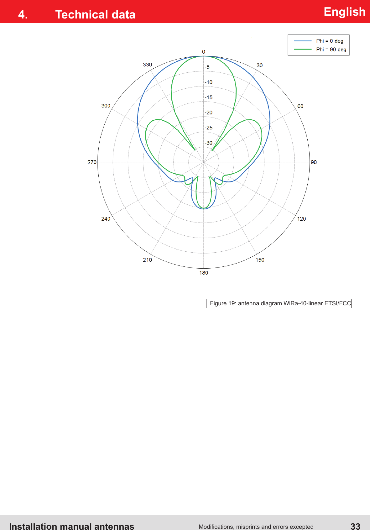
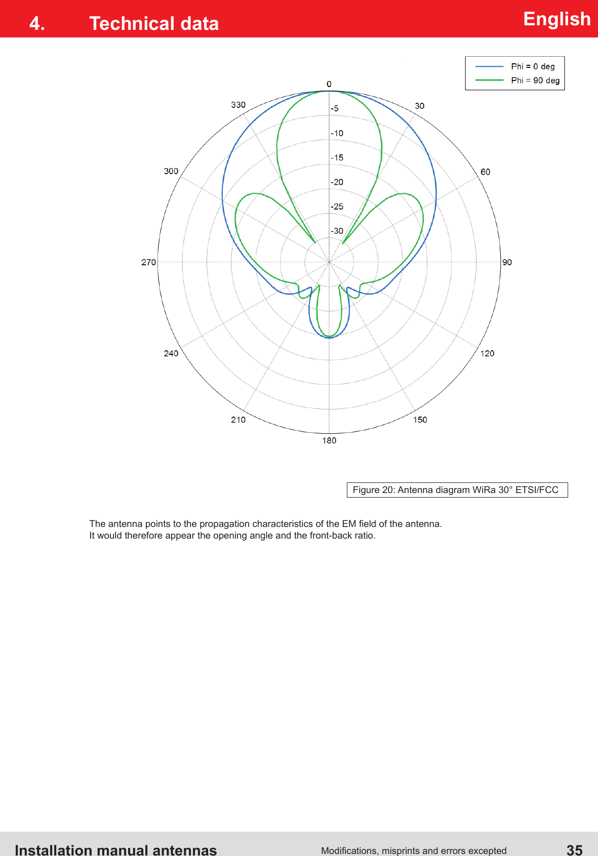
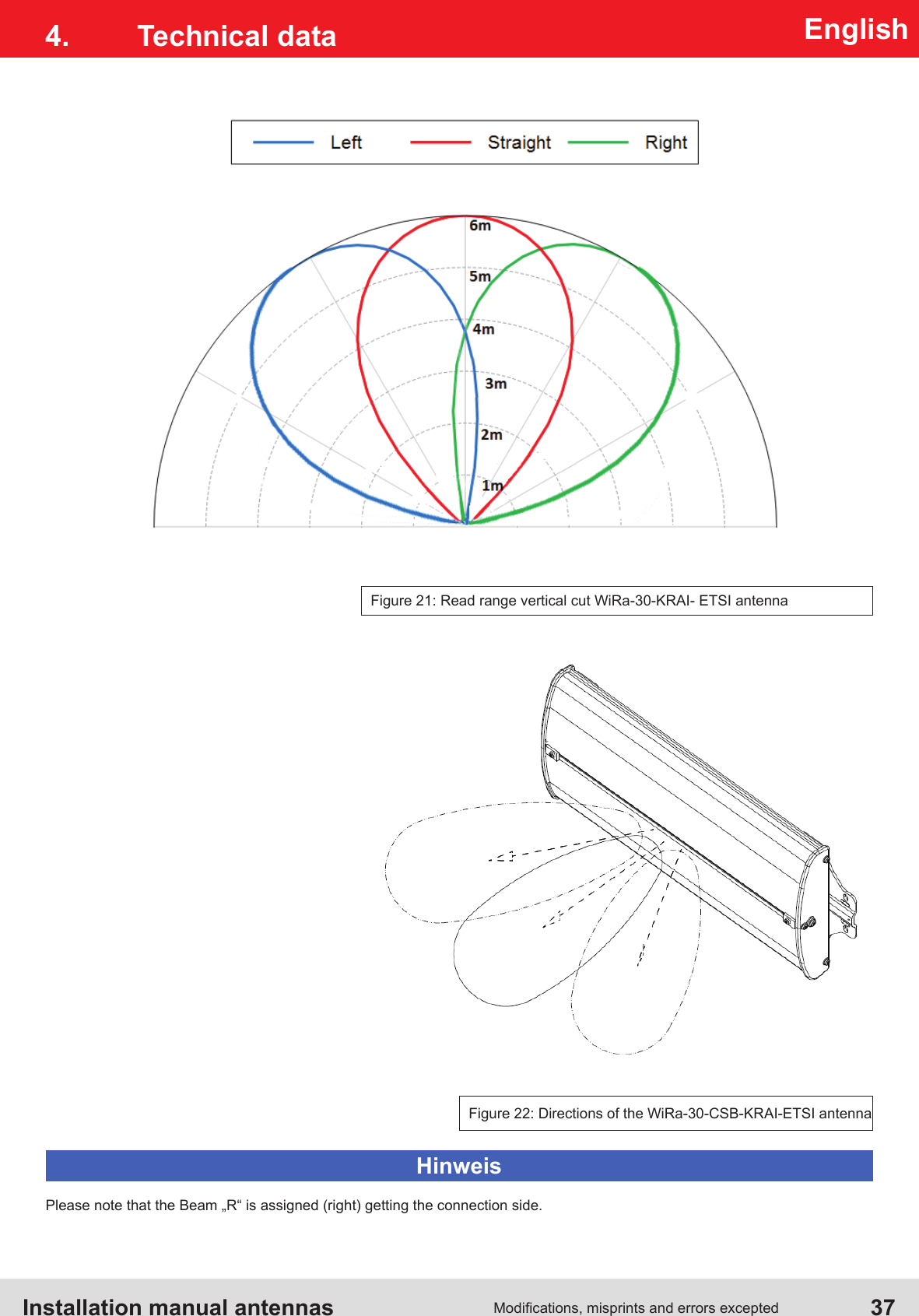
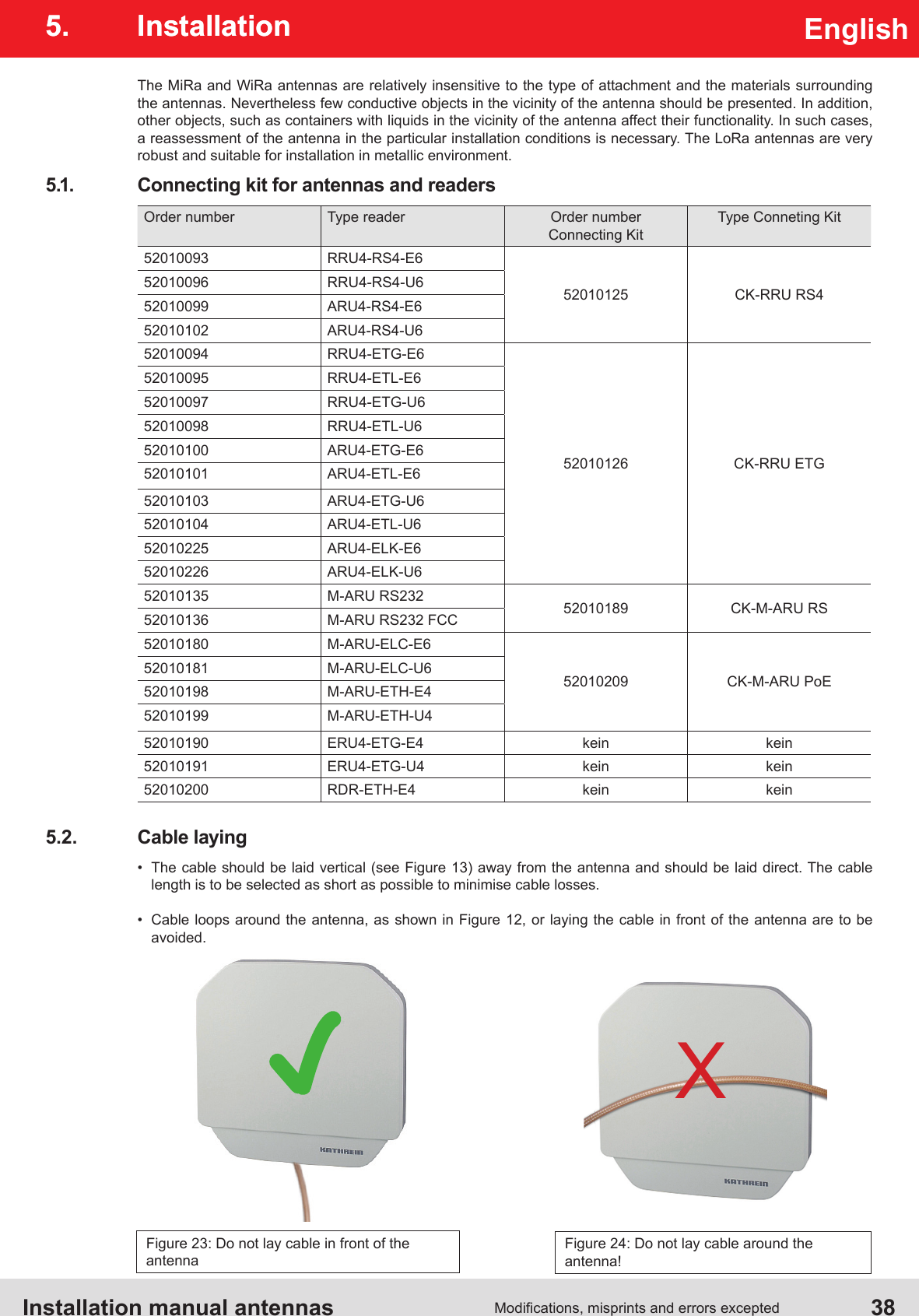
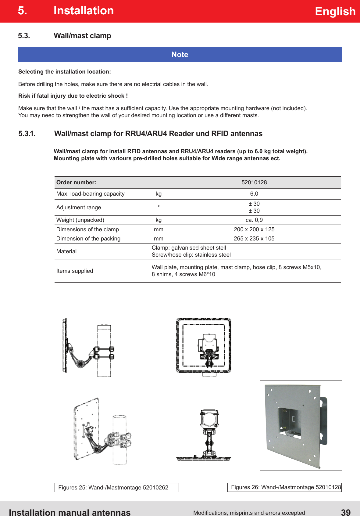
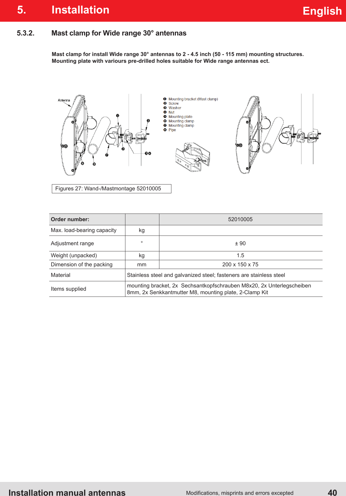
KATHREIN Sachsen ARU4ELCU6 UHF RFID Reader User Manual Antenna Installation Manual
KATHREIN Sachsen GmbH UHF RFID Reader Antenna Installation Manual
Contents
- 1. Antenna Installation Manual
- 2. Installation Manual part 1
- 3. Installation Manual part 2
- 4. User Manual
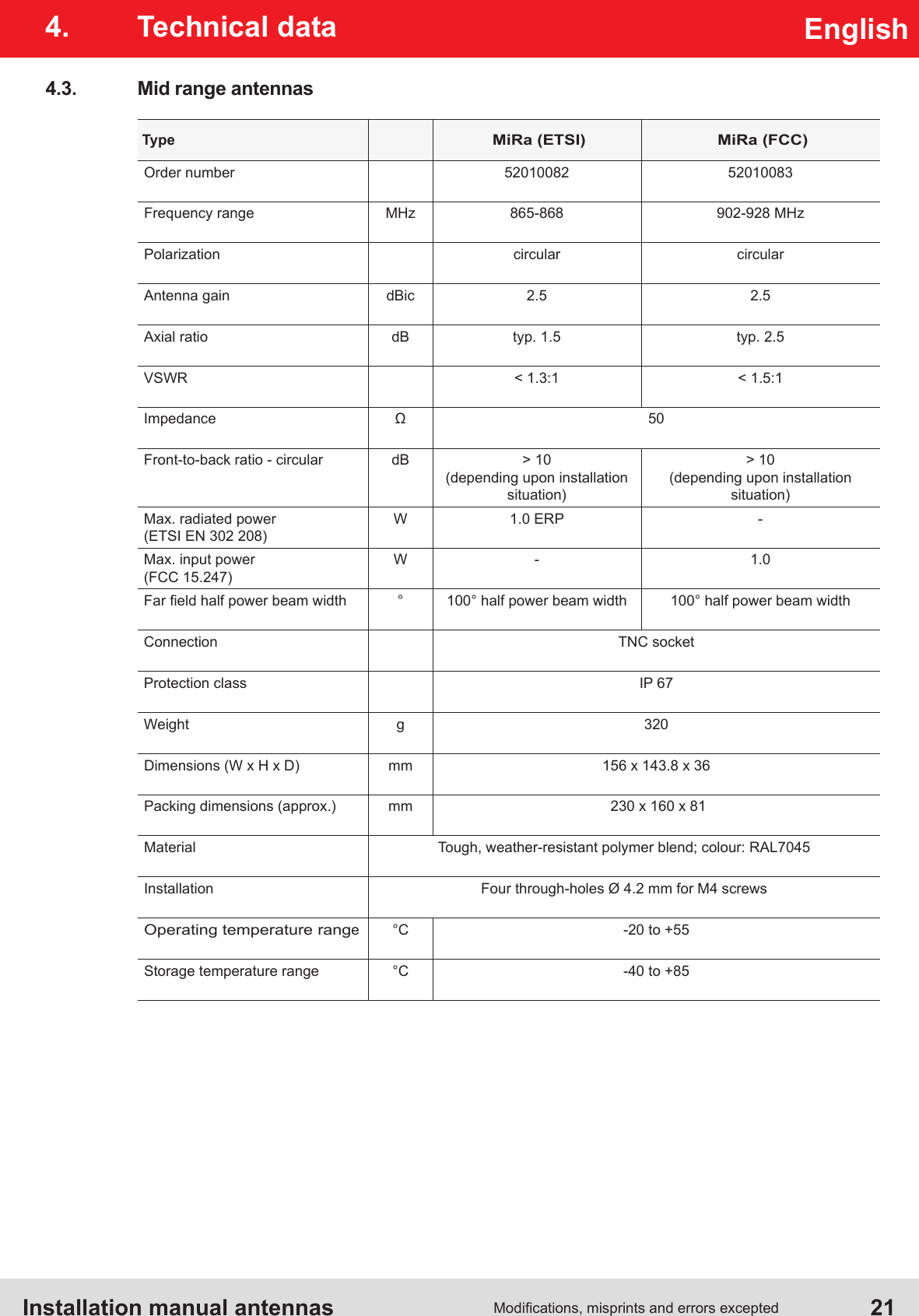
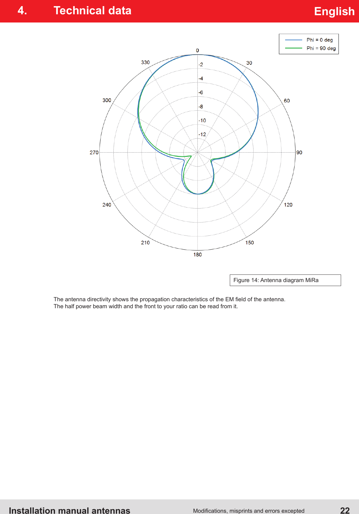
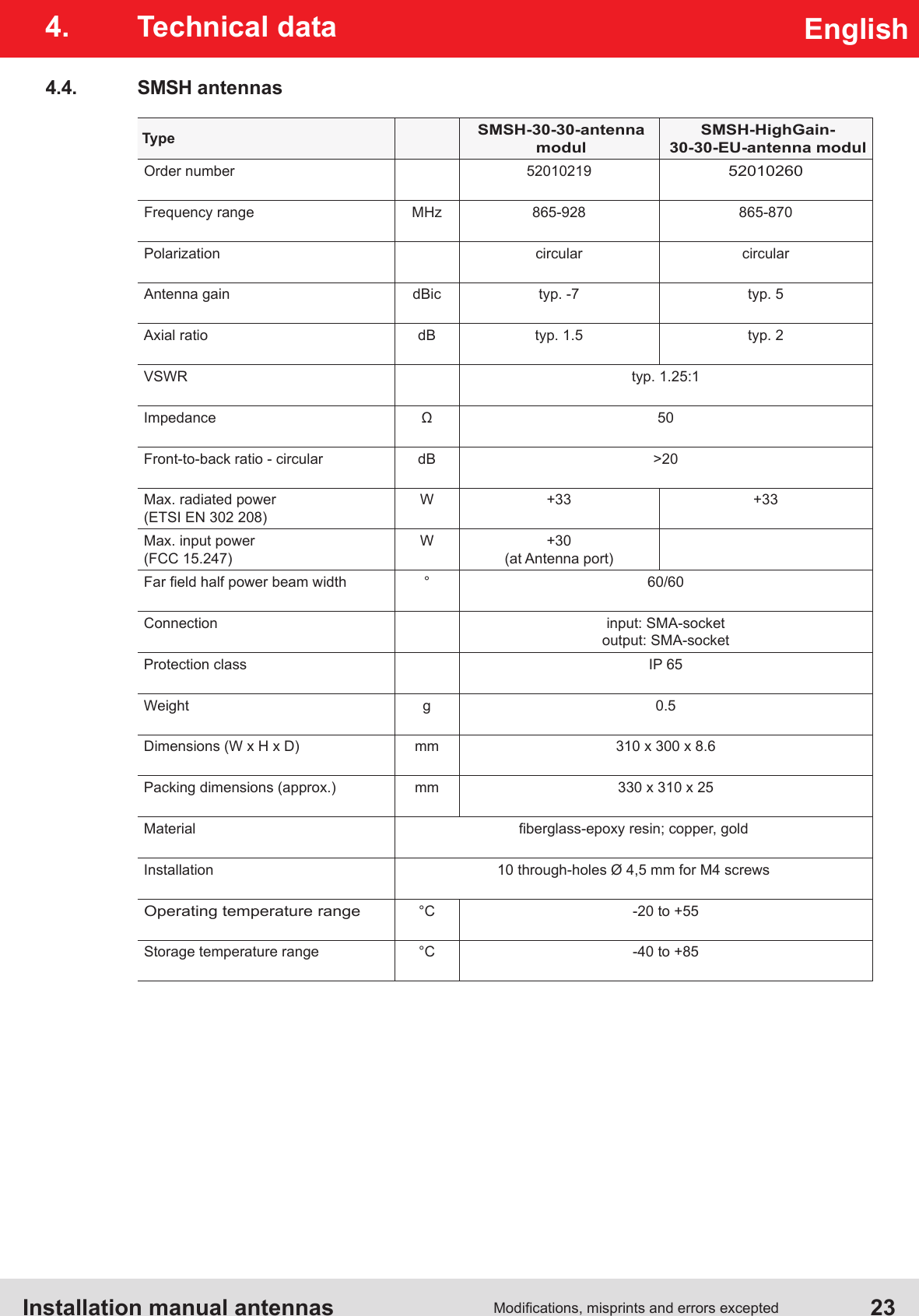
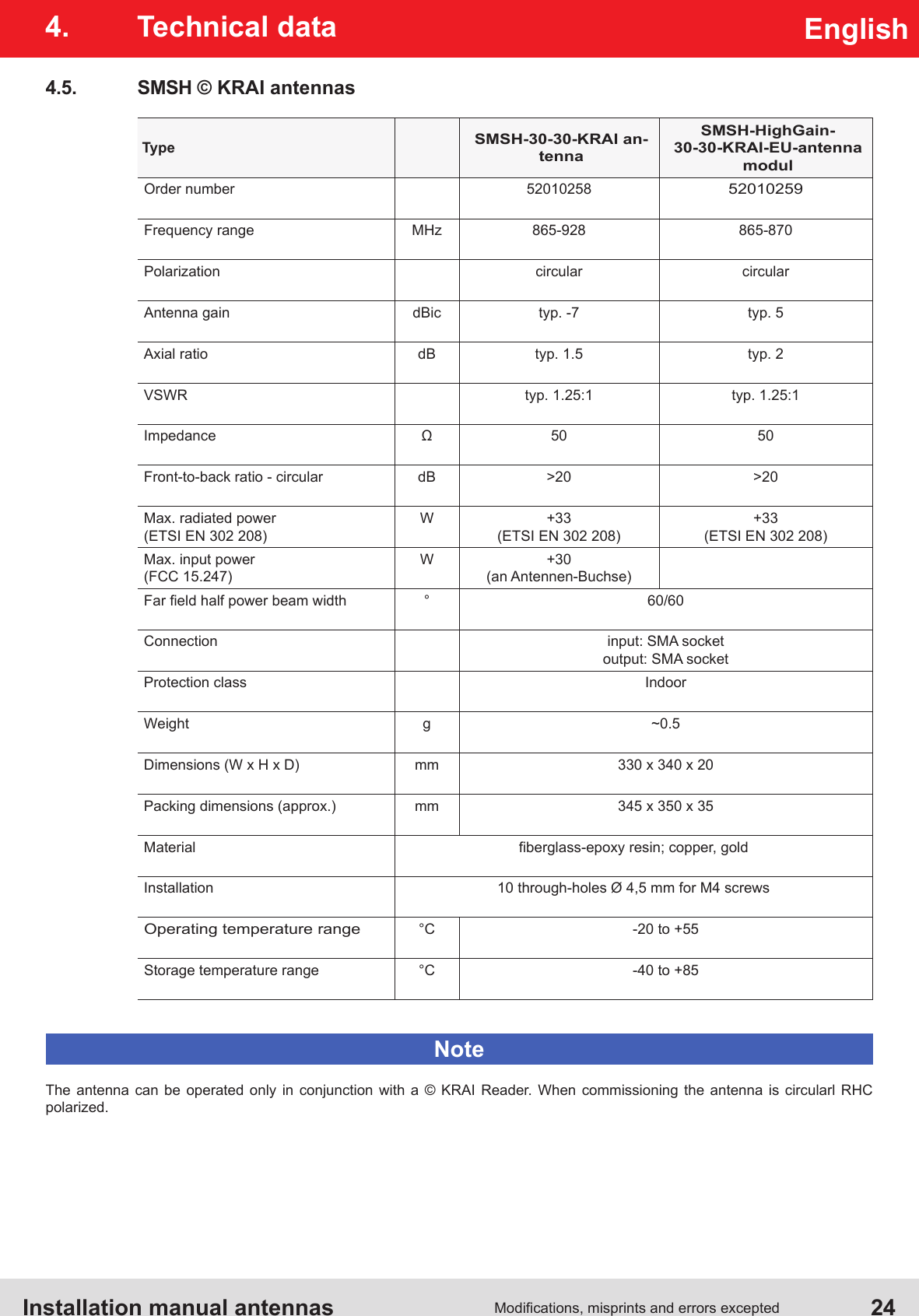
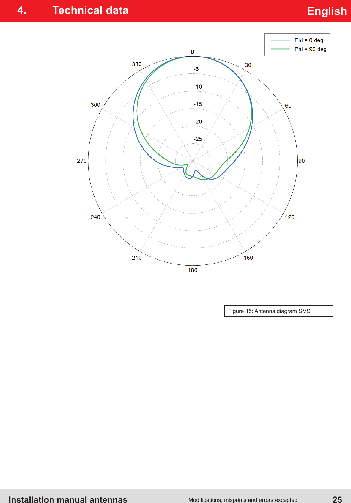
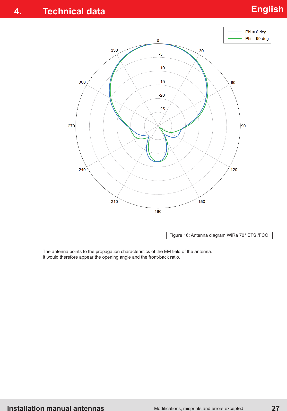
- 5. User Manual Antennas
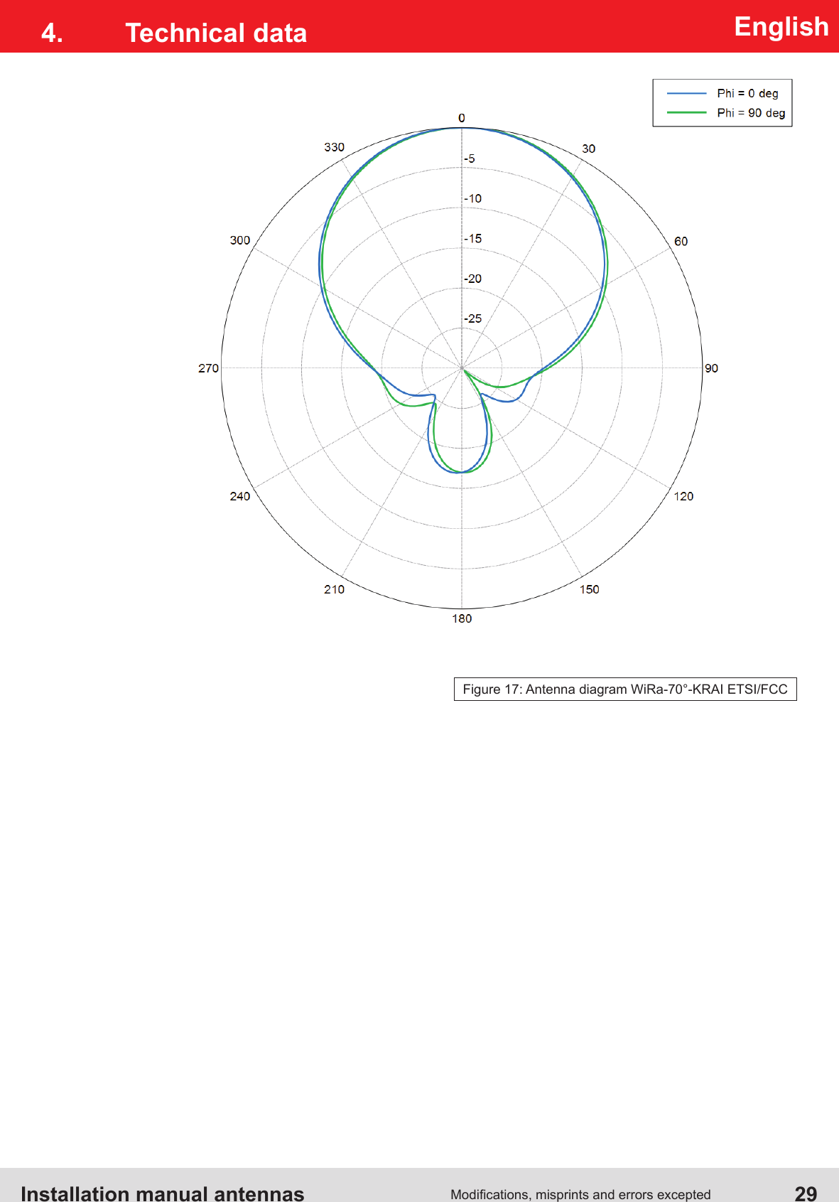
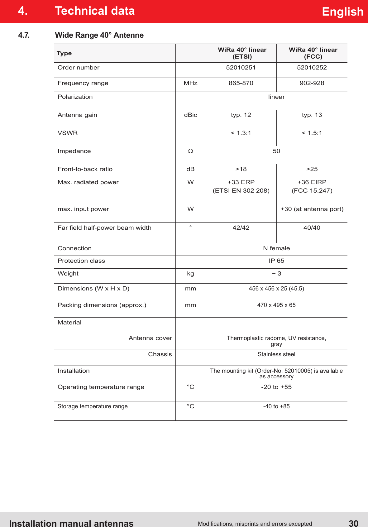
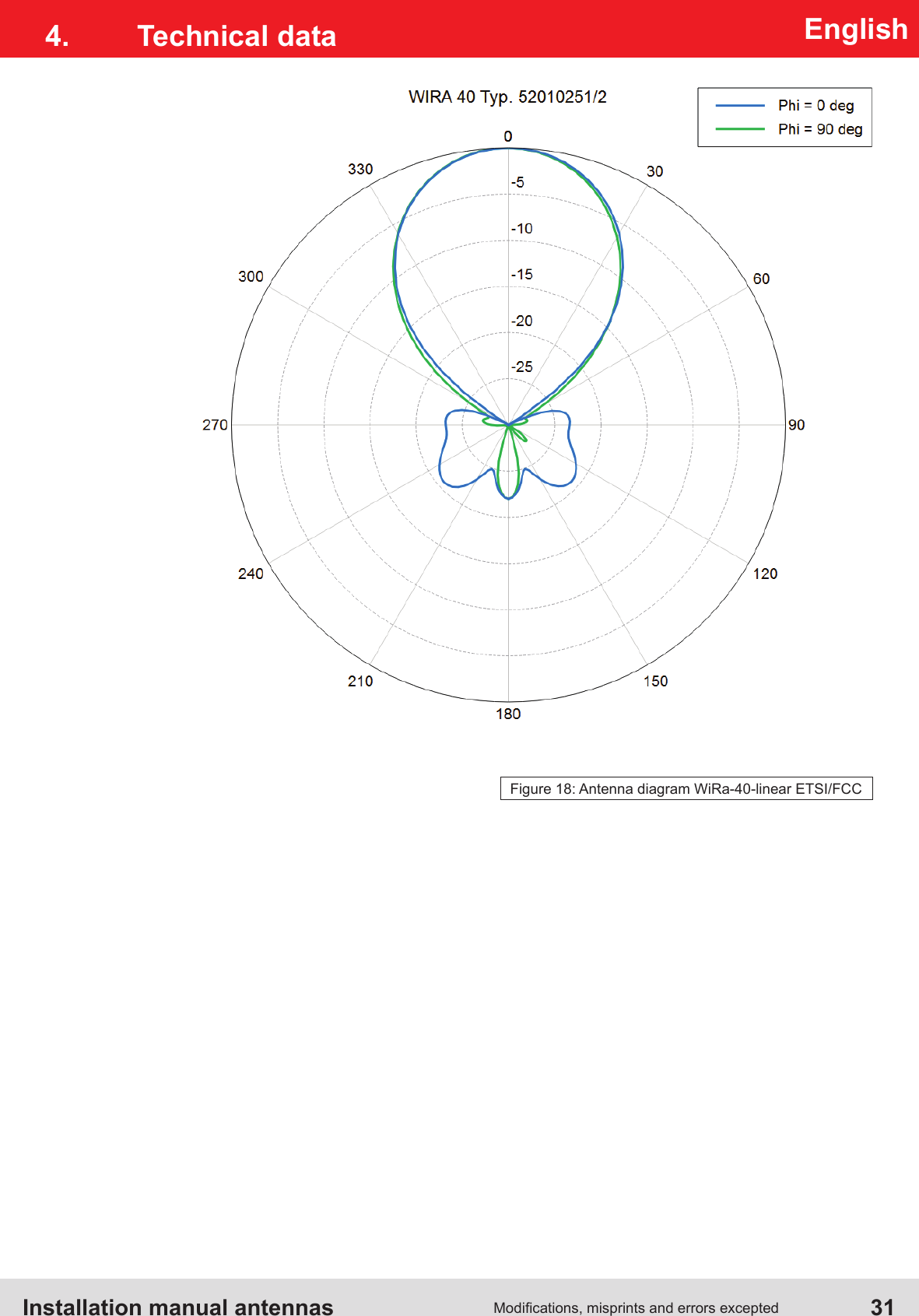
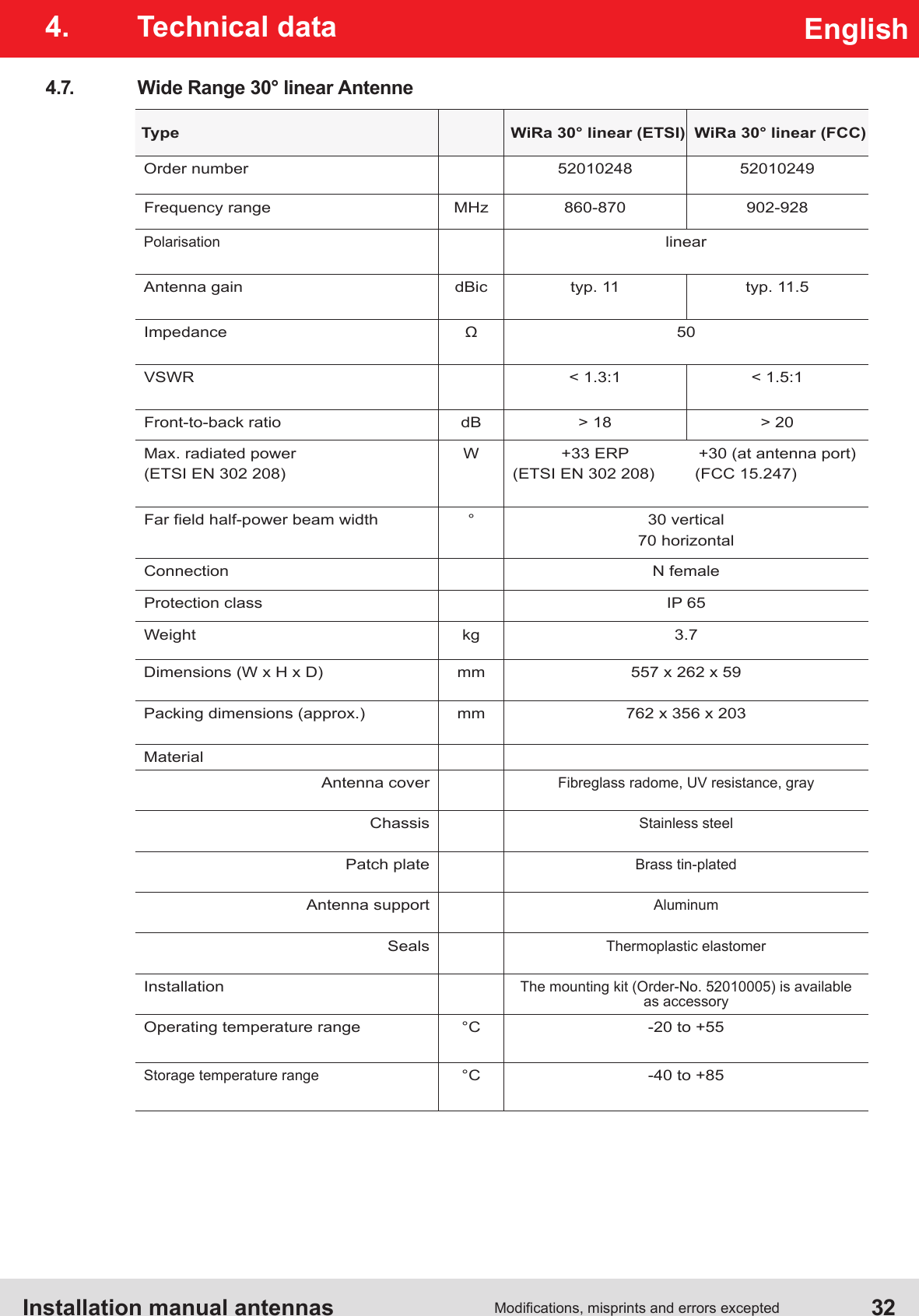
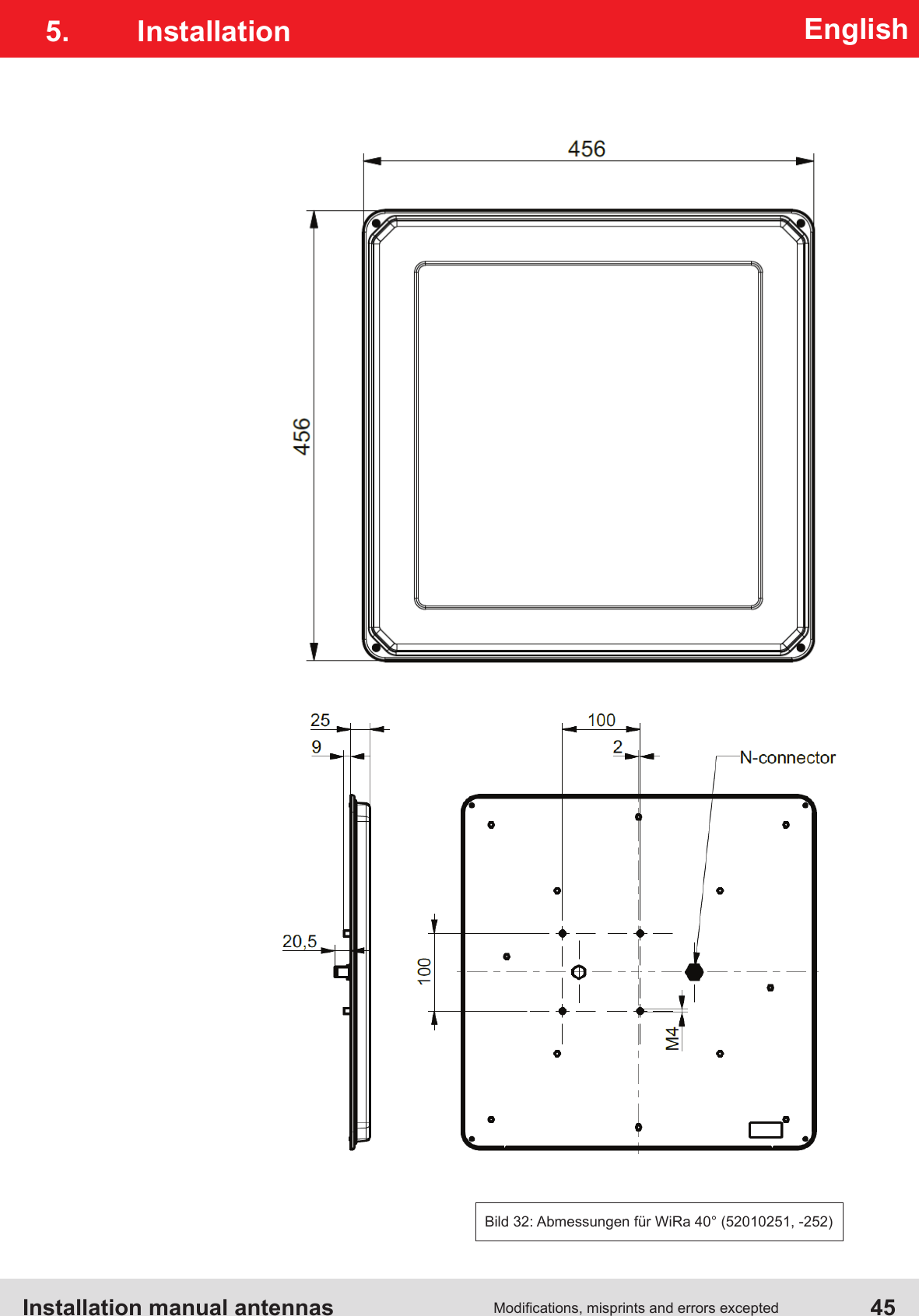
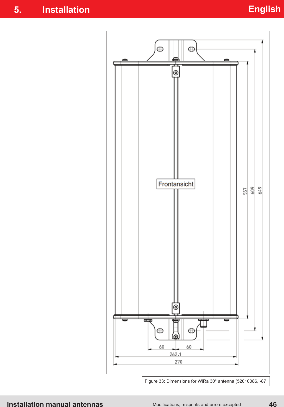
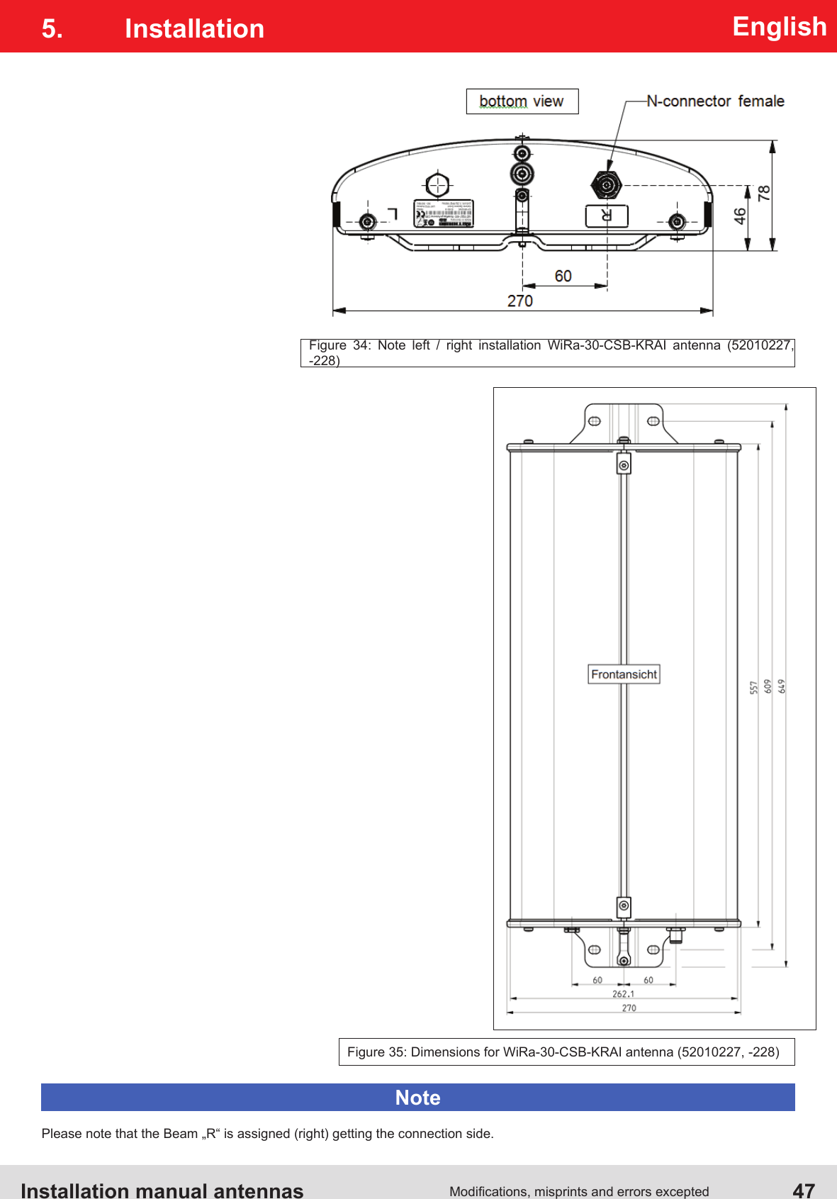
Antenna Installation Manual