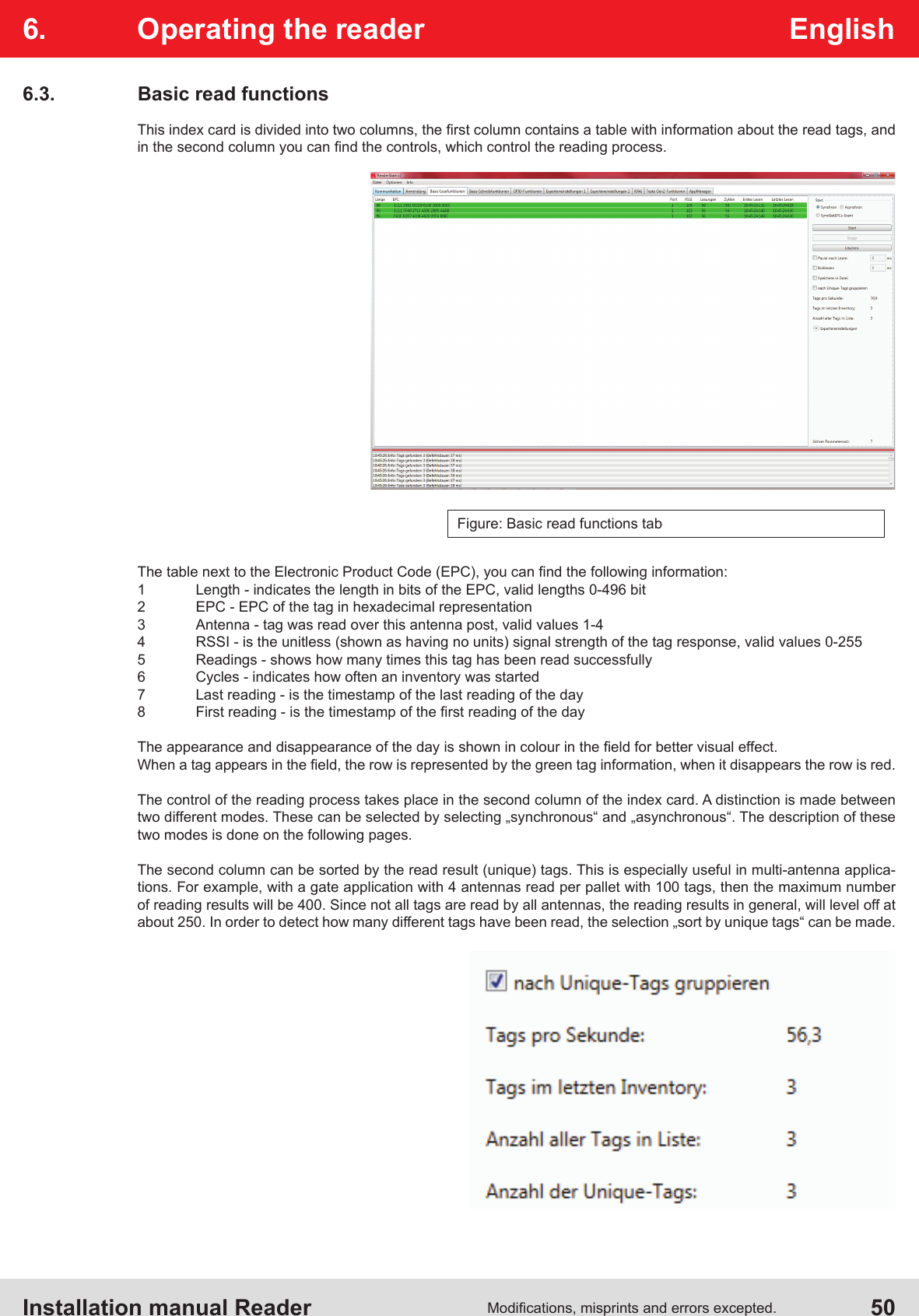
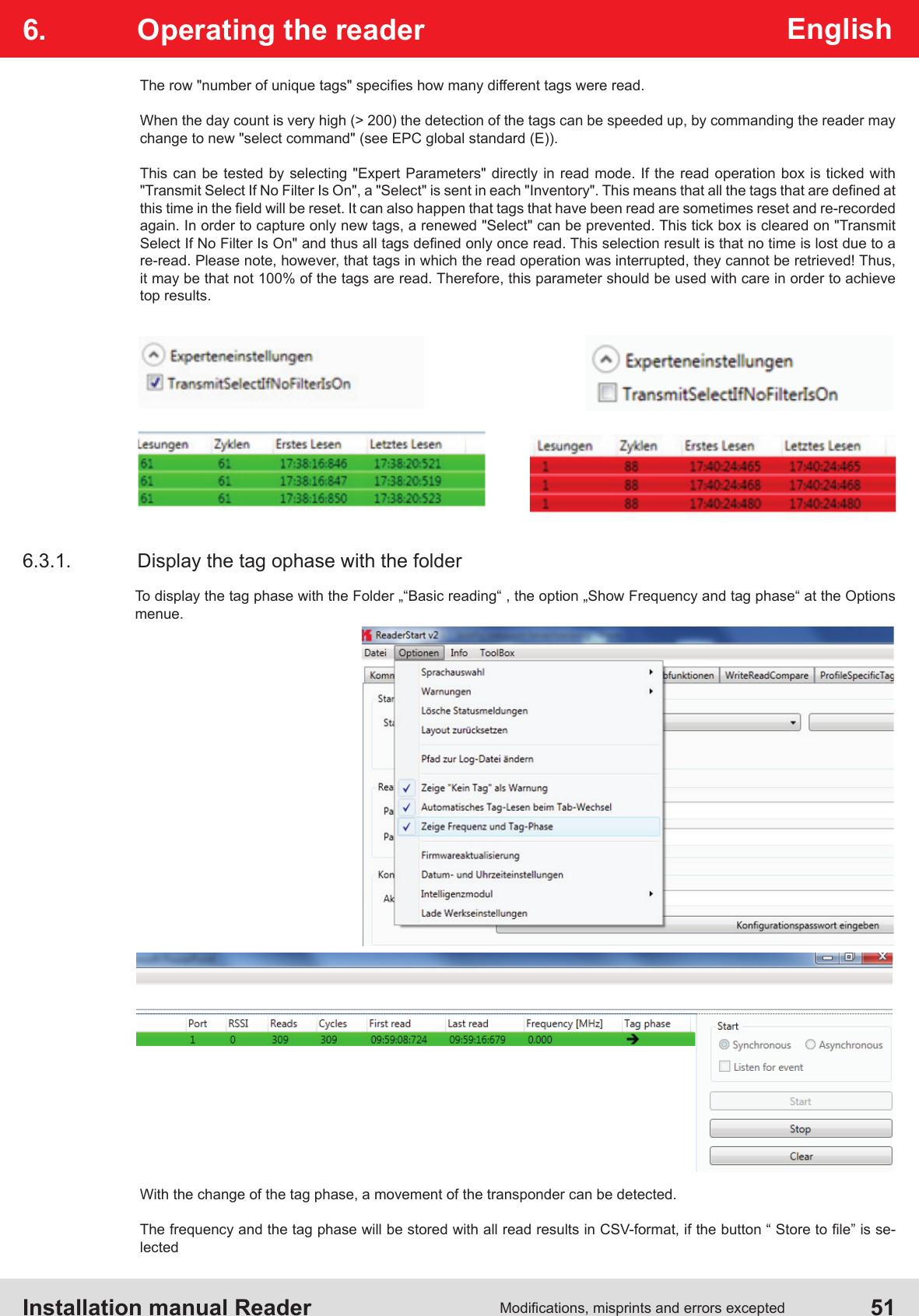
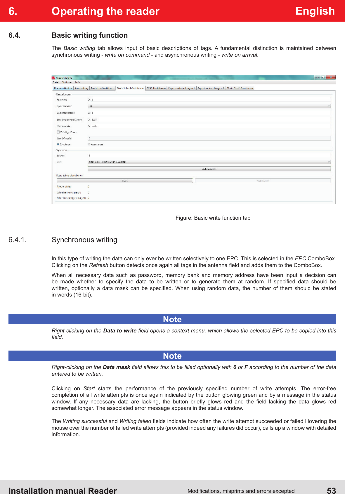
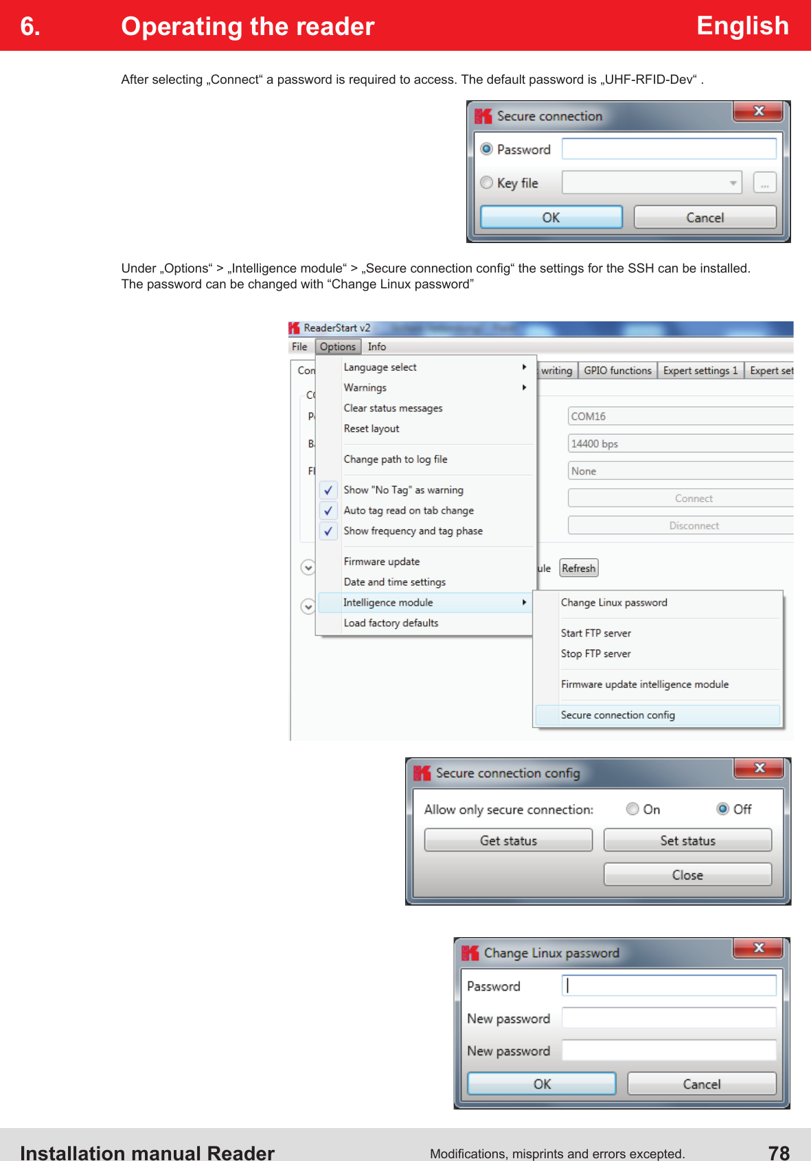
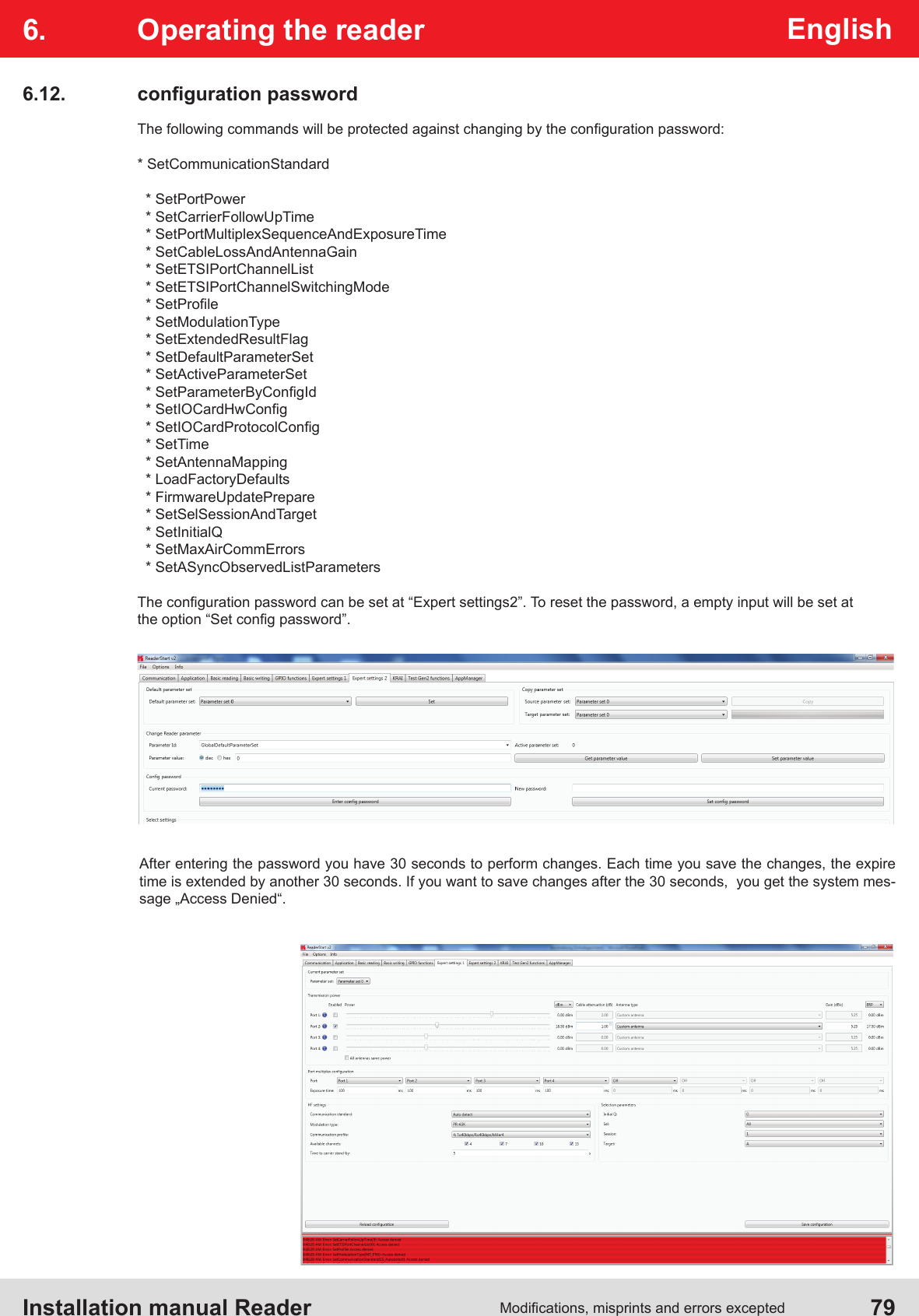
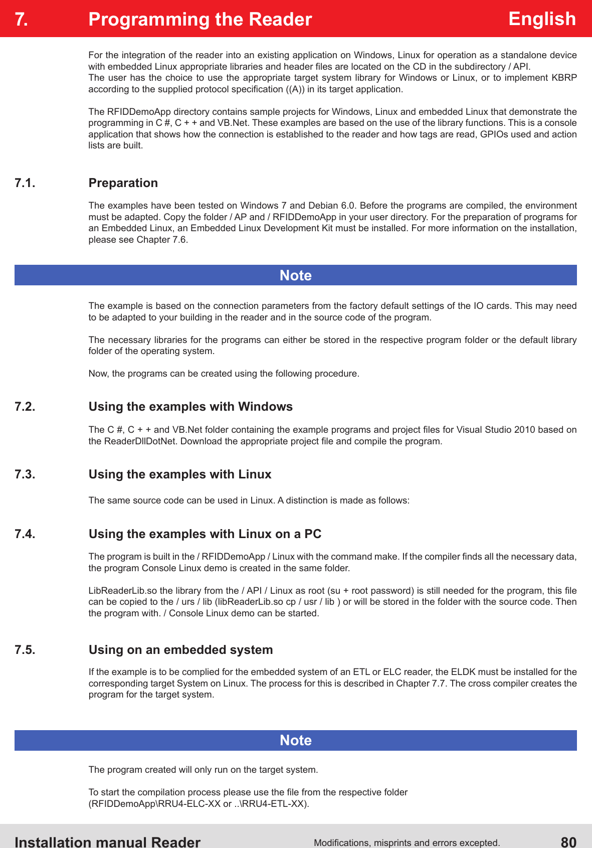
KATHREIN Sachsen RRU4ELCU6 RRU4ELCU6 User Manual Installation Manual

KATHREIN Sachsen GmbH RRU4ELCU6 Installation Manual

Installation Manual

Installation manual for Kathrein RFID UHF-ReaderInstallation manual Reader EnglishThis document is valid for all Kathrein RFID readers and describes the construction and commissioning of the readers.Version 1.03date of creation: 01.06.2012document no.: 936B057RRU4ARU4M-ARUERURDR
Installation manual Reader  2Modications, misprints and errors excepted.EnglishInstallation manual ReaderThis manual applies to the followings ARU4 types:Type: Order number:ARU4-RS4-E6 52010099ARU4-ETG-E6 52010100ARU4-ETL-E6 52010101ARU4-RS4-U6 52010102ARU4-ETG-U6 52010103ARU4-ETL-U6 52010104This manual applies to the followings M-ARU types:Type: Order number:M-ARU-RS232 ETSI 52010135M-ARU-RS232 FCC 52010136M-ARU-ETH-E6 52010198M-ARU-ETH-U6 52010199RFID-UHF-ReaderThis manual applies to the followings RRU4 types:Type: Order number:RRU4-RS4-E6 52010093RRU4-ETG-E6 52010094RRU4-ETL-E6 52010095RRU4-RS4-U6 52010096RRU4-ETG-U6 52010097RRU4-ELC-E6 © KRAI 52010180RRU4-ELC-U6 © KRAI 52010181This manual applies to the followings  ERU types:Type: Order number:ERU-ETG-E4 52010190ERU4-ETG-U4 52010191This manual applies to the followings RDR types:Type: Order number:RDR-ETH-E4 52010200RDR-ETH-U4 52010201
Installation manual Reader  3Modications, misprints and errors exceptedEnglishForeword and general informationThe reproduction or distribution of this document or extracts from it in whatever form and by whatever means (electronic or mechanical) for whatever purpose is permitted only with the prior written permission of Kathrein.Kathrein accepts no liability for omissions or inaccuracies in this document or in relation to the provision or use of the information contained in this document. Kathrein reserves the right to change the products described in this document and does not accept any liability in relation to the application or usage of the products described in this manual.This  document  and  the  information  contained  in  it  are  proprietary  information  of  Kathrein  and  should  be  treated  as  condential. Kathrein provides this document to its customers in connection with contacts of sale for the products described therein. If the person in possession of this document, being a legal or natural person, is not a contractual sales partner of Kathrein, or Kathrein has not intended him by other means as the recipient of the document and the information contained therein, the person in possession is hereby  informed that the use of this document is unlawful and a violation of the rights of Kathrein.Copyright noticeThe information in this manual was correct at the time of editorial deadline.We reserve the right however to make changes at any time and without prior notice.This document was prepared for specialist personal who install, congure and place in operation the reader.ScopeThe information contained in this manual is intended for the support of the development process and as development guidance for the customer. In addition this manual offers supporting information about the standards to be applied at the place of installation  and the relevant safety standards for installation and conguration of the Kathrein reader.General informationThis  manual  contains  information  on  the  installation,  conguration,  operation  and  maintenance  of  the  reader.  In  addition  it  gives  detailed technical data in order better to familiarise the user with the features of the reader. In order to ensure a long working life and fault-free operation, this manual should therefore be read carefully and all the instructions  and information contained in it should be complied with.WarrantySwitching on the AC or DC power supply prior to connecting the LAN cable is considered incorrect installation. Any functional defect arising as a result is excluded from the warranty/guarantee. Before installing or servicing the reader, the person concerned must have read the manual and understood its contents. Kathrein accepts no liability if the customer fails to implement the precautions  listed here. In such cases, any claims under the warranty/guarantee are void. Disposal instructionElectronic equipment is not classed as household waste and must be disposed of properly in accordance with Directive 2002/96/EC OF THE EUROPEAN PARLIAMENT AND OF THE COUNCIL of 27 January 2003 on used  electrical and electronic equipment.At the end of its service life, take this device for disposal at a designated public collection point.Used batteries are special waste!Do not put used batteries into your domestic waste; instead take them to a collection point for used batteries!Further reading on this manual is as ((A)) in section 2.2. further reading or 7th list of references listed.
Installation manual Reader  4Modications, misprints and errors excepted.EnglishList of ContentsForeword and general information   3List of Contents   41.  Safety instructions/information   62. Introduction   92.1.  The reader  92.2.  RFID system  92.3.  Kathrein RFID Antenna Interface (© KRAI) 11 2.4.  Wide Range © KRAI antenna 12 2.5.  SMSH © KRAI planar antenna module 12 2.6.  Further reference material  132.7.  Scope of supply  132.8. Accessories  143. Installation   153.1.  Selecting the installation site  153.2.  Installing the reader RRU / ARU  153.3.  Installing the reader ERU  163.4.  Installing the reader RDR  173.5.  Installing the reader M-ARU  184.  Connections and displays   194.1.  Power supply  194.2.  Ethernet connection  204.3.  RS422-/485 connection  204.4.  RS232 connection  204.5.  ERU connection  214.6.  RDR connection  214.7.  M-ARU connection  224.8.  UART transmission (RS232, RS422, RS485 or similar)  234.9.  Ethernet transmission 25 4.10.  Anschlüsse M-ARU, RS232,       254.11.  Antenna Connection  29
Installation manual Reader  5Modications, misprints and errors exceptedEnglishList of Contents4.12. LED  294.13. Buzzer  295. Software   305.1.  System requirements  305.2. Installation  305.3. Operation  346.  Operating the reader 396.1. Communication  396.2. Application  466.3.  Basic read functions  486.4.  Basic writing functions  516.5.  GPIO functions  536.6.  Expert settings  586.7.  Test Gen2 functions  636.8.  © KRAI Setting  676.9.  App Manager  706.10.  Access Manager  706.11.  Ethernet password  776.12.  configuration password  797.  Programming the Reader 807.1.  Preparation  807.2.  Using the examples with Windows  807.3.  Using the examples with Linux  807.4.  Using the examples with Linux on a PC  807.5.  Using on an embedded system  807.6.  Installation Embedded Linux Development Kit (ELDK)  817.7.  Installation Linux application  828.  List of references   859.  Contact address   86
Installation manual Reader  6Modications, misprints and errors excepted.English1.  Safety instructions/informationKeyCaution!NoteBefore starting installation work or replacing the unit, the accompanying manual must be read carefully and its  contents understood.The detailed information in the data sheets and in this manual must be complied with carefully during installation and operation of the reader!The  installation  team  must  be  properly  qualied  and  familiar  with  the  safety  regulations  applicable  in  the  country concerned.Connection, installation and maintenance work, as well as all other work on the unit, may only be carried out by  properly qualied and trained employees.The unit may only be used for the purpose intended by the manufacturer.Unauthorized changes to the unit and the use of spare parts and peripheral devices which are not sold or recommended by the manufacturer can result  in res, electric  shocks and injuries.  Such actions therefore  result in  exclusion of liability and make the manufacturer’s warranty/guarantee null and void.The applicable version of the manufacturer’s warranty is that which was valid at the time of purchase. We accept no liability  for unsuitable manual  or automatic adjustments  made to the  unit's parameters and  inappropriate use of  the unit.Repairs may only be undertaken by personnel authorised to perform them. Opening or attempting to repair the  unit makes all guarantee/warranty claims null and void! Improper work on the unit may jeopardise electrical safety.The manufacturer is not liable for accidents caused by the user opening the unit!When carrying out work on the unit, the valid safety regulations must be complied with.Supply voltageMake sure that the mains cable (power supply cable) is not damaged. If the mains cable is damaged, the device must not be used. Instead it must be disconnected from the mains and repaired by a qualied technician. Use only  the power supply unit supplied!Risk of fatal injury due to electric shock!The device may be operated only at the stated supply voltage (see the rear of the device or external power supply unit)!If the supply voltage is too high, there is a risk of re!General safety notesImportant!Indicates a potentially dangerous situation which, if disregarded, can lead to injuries ranging from minor to severe and/or damage to the unit.Information intended to make a specic topic easier to understand and/or enable optimal use of the unit functions.Important!
Installation manual Reader  7Modications, misprints and errors exceptedEnglish1.  Safety instructions/informationCE marking for the Kathrein RFID reader with type designation "E6"Appropriate means are provided to dissipate the heat generated within this equipment. The device must however not be installed in a cabinet or on shelves with insufcient ventilation. The ventilation slots on the device must not be covered.There is a risk of re!VentilationProtect the device from moisture, dripping water and spraying water. The device must not be placed close to sources of heat, exposed to direct sunlight or operated in a damp environment. The device may not be operated only is moderate climatic zones. It is unsuitable for use under tropical conditions! Do not place anything which has a naked ame on the device! 1)There is a risk of re!Moisture, direct sunlight, heat, naked amesThis reader is designed “E6” for operation as per EN 302208. When the unit is operated with antennas connected, the human exposure regulations in accordance with EN 50364 must be complied with. Ensure a minimum clearance of 20 cm between the antenna and the human body, and comply with the operating instructions for RFID antennas. In some circumstances, heart pacemakers may suffer interference if wearers are close to the antenna when the unit is in operation (reader and antenna). In case of doubt, the people affected are requested to contact the manufacturer of their pacemaker or their doctor.The reader output power must be reduced as a function of the antenna cable length and the antenna gain.Radiated electromagnetic eldsCE marking for the Kathrein RFID reader with type designation "U6"The reader with the identier "U6" are designed to operate under FCC Part 15 and with the FCC ID "WJ9" on the FCC homepage to nd.This device complies with part 15 of the FCC Rules. Operation is subject to the following two conditions: (1) This device may not cause harmful interference, and, (2) This device must accept any interference received including interference that may cause undesired operation.Industry CanadaUnder Industry Canada regulations, this radio transmitter may only operate using an antenna of a type and maximum (or lesser) gain approved for the transmitter by Industry Canada. To reduce potential radio interference to other users, the antenna type and its gain should be so chosen that the equivalent isotropically radiated power (e.i.r.p.) is not more than that necessary for successful communication.This radio transmitter has been approved by Industry Canada to operate with the antenna types listed at page 9 with the maximum permissible gain and required antenna impedance for each antenna type indicated. Antenna types not  included in this list, having a gain greater than the maximum gain indicated for that type, are strictly prohibited for use with this device.Modications or conversions which are carried out on this unit without the express permission of Kathrein may invalidate the FCC permit for the operation of this unit.Important!Important!Important!
Installation manual Reader  8Modications, misprints and errors excepted.English1.  Safety instructions/informationNoteFollowing corresponding tests, it has been ascertained that this unit adheres to the limit values for class B digital units in accordance with part 15 of the FCC regulations. These limit values are intended to provide private user's systems with appropriate protection against harmful radio interference. This unit generates and uses energy in the radio frequency range and is also able to radiate this; if it is not installed and used in accordance with the regulations, the unit may cause harmful radio communication interference. However, there is no guarantee that interference will not occur in a specic system. If this unit causes harmful radio or television reception interference, which can be ascertained by switching the unit on and off, we recommend that the user attempts to rectify this  interference via one or more of the following measures:-  Realign the receive antenna or change its position.-  Increase the distance between the unit and the receiver.-  Plug the unit into a socket in a current circuit other than that to which the receiver is connected.-  Seek advice from the retailer or an experienced radio/television technician.This equipment complies with IC RSS-102 radiation exposure limits set forth for an uncontrolled environment.  This equipment should be installed and operated with minimum distance 20cm between the radiator & your body.Warning regarding exposure to RF radiationNoteTo meet part 15 of the FCC regulations in the United States, the system must be properly installed to guarantee adherence to the certication regulations according to part 15. The operator and the specialist company which carries out  installation  are  responsible  for  ensuring  that  only  certied  systems  are  used  in  the  United  States.  Use  of  this system in any other combination (e.g. several antennas which transmit the same information in the same location)  is expressly prohibited.Note regarding proper installation:Important!FCC RF Radiation Exposure StatementThis transmitter must not be co-location or operating in conjunction with any other antenna or transmitter.This equipment complies with FCC RF radiation exposure limits set forth for an uncontrolled environment.This equipment should be installed and operated with a minimum distance of 20 centimeters between the radiator and your body.
Installation manual Reader  9Modications, misprints and errors exceptedEnglish2. Introduction2.2.  RFID systemAn RFID system consists of the control computer of the actual reader, antennas, antenna connection cables and the tags. The gure below shows the schematic structure of the system:The tags consist of an antenna and a small chip. The chip is the true carriers of the information,the EPC number. This number can be identied products or product groups. Alternatively, the EPC can be overwritten with new information.To read the tag information, the reader sends an RF carrier by an active antenna and thus supplies the tags in the RF eld with energy. If the information in one tag should be read, this tag should be rst selected (inventoried) from the population of tags. Upon successful completion of the inventory, the EPC number of each tag can be read and sent to the PC. Additional information can be attached to the EPC, for example the antenna which read it the time point at which it was read. Figure: continuous operation  ETL and ELC RFID systemBy the ETL and ELC Reader is an industrial PC with Linux operating system is integrated.RS232RS422/485Ethernet2.1.  The readerThe Kathrein RFID (Radio Frequency Identication) reader RRU4 is a multi-protocol-capable device for reading active and passive RFID tags in the frequency range from 865 to 868 MHz for Europe type “E6” and 902 to 928 MHz for the American market type “U6”. As supplied the unit can read and write tags in accordance with the EPC-Gen2 standard.  Additional protocols can be loaded using software updates.The device has a maximum of four external antenna ports for connection of the transmission/reception antennas for communication with RFID tags.For integration into a variety of infrastructures, the device has different communication interfaces depending on the variant. The power supply is provided by a 4-pin M12 panel connector in A coding.Important!The reader operates using the frequency hopping process, so as to avoid faults and interference between readers. Within the FCC area this procedure is mandatory. The readers changes its transmission frequency randomly, with equal distribution across the 52 available channels. Each channel is used for max. 400ms in an interval of 20s.
Installation manual Reader  10Modications, misprints and errors excepted.EnglishFor testing and parameterizing the reader the Demo Software“Reader Start v2”can be used.The communication between the“Reader Start v2” and the reader is based on the DLL, which includes the commu-nication protocol ((A)). For specic applications the user can build its own control software based on the reader DLL. The DLL includes all the relevant commands and functions, which are needed to control the readerFigure: Testing and conguration of the RFID systemRS232RS422/485EthernetBy the ETL and ELC Reader an industrial PC with Linux Operating System is integrated.RS232RS422/485EthernetFigure: Continuous operation of the ETL and ELC RFID systemThe control software must be created by the user.The user-specic control software can run on ETL reader directly. Thus, a stand-alone operation without permanent network connection is possible.The demo software Reader Start is included.2. Introduction
Installation manual Reader  11Modications, misprints and errors exceptedEnglish2. Introduction2.3.  Kathrein RFID Antenna Interface © KRAIBy using Kathrein © KRAI antennas, reading rates can be increased by 33% compared to simple circular antennas.The Kathrein-RFID Antenna Interface © KRAI consists of a digital control bus, which enables connection between the RFID reader and the RFID antennas in order to allow control and regulation tasks in remote antennas.The phase control elements integrated in the © KRAI antennas enable static or  dynamic adjustment of antenna characteristics. Due to this, four different polarizations can be selected for the new 70° Wide Range antenna (type 52010193 WIRA-70-KRAI-ETSI): RHCP / LHCP/ horizontal linear / vertical linearOne can choose between static polarization and automatic switch-over. As the Kathrein-RFID Antenna In-terface © KRAI is transmitted over the standard antenna cable, no additional lead or connection is required to control the new antenna types.The Kathrein RFID © KRAI system permits the cascading of up to 8 SMSH antennas at a single antenna port. This allows selective access to up to 32 individual antennas. This allows the reading result to be linked to the antenna recognition (e.g. antenna 3 (5)) and be output.With the new © KRAI product series Kathrein has introduced a revolutionary system.
Installation manual Reader  12Modications, misprints and errors excepted.English2.4.  Wide Range © KRAI antennaPlease ensure that the rmware of your KRAI-capable reader and the reader start conguration software are release 2.40 or higher.NoteNoteWiRa-70-KRAI antennas cannot be cascaded.A maximum of 8 SMSH antennas can be cascaded per rea-der port.2.5.  SMSH © KRAI planar antenna module:
Installation manual Reader  13Modications, misprints and errors exceptedEnglish2.6.  Further reference materialIn  order  to  congure  the  reader  correctly  and  adapt  it  to  the  respective  application,  detailed  knowledge  of  the EPCGlobal standards of GS1 is necessary ((E)). This standard describes the principle of operation of the interface  between the tag and reader.The parameters  available for  the conguration  of the reader  is available  as described  in the  “conguration manual Reader” ((B))The reader is controlled via the Kathrein-Reader protocoll (KBRP). The document “communication protocol” ((A)) in the current version contains a detailed description of the protocolNoteThe versions of the documents must match the software version of the reader. The CD supplied contains the current documents for the reader rmware supplied.2.7.  Scope of supplyThe package includes a CD next to each reader with a parameter, and test software  (Reader Start), programmingexamples, DLL and operating((E))  EPCTM Radio-Frequency Identity Protocols Class-1 Generation-2 UHF RFID in version V1.2.0 : www.epcglobalinc.org„communication protocol“ ((A)) for software developers„congurational manual reader“ ((B)) for commissioning„installation manual reader“ ((C)) Setup and installation"installation manual antenna“ ((D)) Setup and installation„EPCGlobal standard“ ((E)) for software developers„Putty is SSH and Telnet-Client“ ((F)) for software developers
Installation manual Reader  14Modications, misprints and errors excepted.English2. Introduction-  Cable sets (without antenna cable)Order number Type for Series Product type52010125 CK-RRU RS4 RRU4/ARU4 Power supply cable, RS 422/485, GPIO, length 1.5 m52010126 CK-RRU ETG RRU4/ARU4 Power supply cable, Ethernet interface cable, GPIO-cable, length 1.5 m52010189 CK-M-ARU RS M-ARU Combination cable for power supply GPIOs, RS232 interfacelength 1.5 m52010209 CK-M-ARU PoE M-ARU Combination cable for power supply and PoE interface, length 1.5 m52010238 R-CC 10 ETH RRU4/ARU4/M-ARUEthernet Connecting Cable, length 10 m52010239 R-CC 10 GPIO RRU4/ARU4 GPIO Connecting Cable, length 10 m52010240 R-CC 10 DC RRU4/ARU4 DC power supply Connecting Cable, length 10 m52010241 R-CC 10 RS M-ARU Connecting Cable M-ARU, length 10 m2.8. AccessoriesThe following accessories are available for the reader (if you have questions about the accessories, please contact  our Sales Ofce):-  Antennas: For use with UHF-RFID antennas; we recommend the Kathrein antenna types ULoRa, LoRa,  MiRa, WiRa. These antenna types are available for all frequency ranges.The mentioned types of antennas are available for all frequency ranges and in screwed condition tight IP 65.Order number Type Connector 1 Connector 2  Lenght (cm)52010174 R-AC 3 TNC-TNCRTNC TNC ReverseLL240 ex, 30052010175 R-AC 6 TNC-TNCR LL240 ex, 60052010176 R-AC 10 TNC-TNCR LL240 ex,100052010177 R-AC 15 TNC-TNCR LL240 ex,150052010178 R-AA TNC-N(f-m) TNC (socket) N-Socket52010090 R-AC 3 SMA-TNCR SMA (socket) TNC (socket) RG 58, 30052010208 R-AC 05 SMA-SMA SMA (socket) SMA (socket) RG 58, 50Order number Type Product type52010005 MK-WiRa30 Wall mount/mast mounting set for 30° WiRa antennas52010128 MK-ARU WiRa70 Wall mount/mast mounting set  for RFID antennas and RRU4/ARU4-readers (to 6.0 kg total weight).-  Mounting Accessories-  Protective CoversOrder number Type Product type52010179 R-RPA 115-230V/24V RRU / ARU 230V power supply with safty plug (Lörar); 24V DC power supply with M12 socket 4-pin, A-coded52010192 R-ERPA 115-230V/24V ERU 230V power supply 24V DC cable plug connector 2.5 mmOrder number Type Product type52010127 Protective covers set for the RRU and ARU reader seriesAccessories for RRU4/ARU4 reader with screw caps for 3x antenna input (R-TNC) and 2x digital (M12)-  Readers power supply -  Antenna cable
Installation manual Reader  15Modications, misprints and errors exceptedEnglish3. InstallationFigure: Far side RRU4 with dimensions(M6 x 10 screw)3.1.  Selecting the installation siteWhen the connections are plugged in, the device satises the protection class IP65 (RRU and ARU) and class IP40 (ERU and RDR). When selecting the installation location, make sure there is sufcient space around it for appropriate dissipation of the heat generated by the device. Do not install it close to external sources of heat. The maximum operating temperature listed in the  data sheet must not be exceeded. The support surface must have a sufcient lead-bearing capacity/strength.3.2.  Installing the readerThe device has threaded holes at the rear for attaching the reader. The dimensions of the holes pattern can be found in the drawing below. For ease of installation a bracket is available as an accessory, which offers the option of  mounting on a mast or wall.
Installation manual Reader  16Modications, misprints and errors excepted.EnglishFigure: ERU with dimensions3.3.  Installing the reader ERU3. Installation
Installation manual Reader  17Modications, misprints and errors exceptedEnglishFigure: RDR with dimensions3.4.  Installing the reader RDR3. Installation
Installation manual Reader  18Modications, misprints and errors excepted.EnglishFigure: M-ARU with dimensions3. Installation3.5.  Installing the reader M-ARU
Installation manual Reader  19Modications, misprints and errors exceptedEnglish4.  Connections and displaysFigure: General view of the RRU42   13   4PIN Allocation1 +24 V DC23 GND4Allocation of the power cable (Order-No.. 52010125 und 52010126)Depending of the device variant, the reader has various connection options. The illustration below shows an RRU and ARU standard reader with all its connection options. Details of the connections and the pin assignments of plugs  and sockets are provided in the following pages.Sockets, from left to right Description1 Communication connection: M12 (depending on the device variant)2 Power supply connection: M12 male, 4-pin, A-coded3 GPIO connection 1: M12 female, 8-pin, A-coded4 GPIO connection 2: M12 female, 8-pin, A-coded5 Antenna connection 1: R-TNC 50 Ohm6 Antenna connection 2: R-TNC 50 Ohm7 Antenna connection 3: R-TNC 50 Ohm8 Antenna connection 4: R-TNC 50 OhmStatus indicators: 3 coloured LEDs (red, green, orange)4.1.  Power supplyThe power supply is arranged as a four-pin round-pin plug with and M12 connection thread in A-coding.Only power supply units with power limitation are approved for operation with the device. This means that the  secondary side of the power supply unit is limited to a power of maximum 100 W.Note
Installation manual Reader  20Modications, misprints and errors excepted.EnglishPIN Allocation1 TD+2 RD+3 TD-4 RD-1   24   3PIN Allocation RS422 Allocation RS4851 RxD+ RxD/TxD+2 RxD- RxD/TxD-3 TxD+4 TxD-5 GND GND1   24   35 Zentral-PinPIN Allocation 1 CTS2 RxD3RTS4 TxD5 GND1   24   35 Zentral-PinAllocation of the serial interface cable (Order-No. 52010125) valid for RS232, RS422/4854.  Connections and displays4.2.  Ethernet connectionThis data interface is arranged as a 4-pin M12 socket with D-coding. Only shielded cables may be used.4.3.  RS422/485 connectionThis interface is arranged as a 5-pin M12 socket with A-coding. Only shielded cables may be used.The interface card of the reader is equipped with a combined RS485/RS422 interface. The changeover between RS485  and  RS422  is  performed  using  the  conguration  tool.  For  operation  as  RS422,  the  RS485  cables  are connected to RX.4.4.  RS232 connectionThis interface is also arranged as a 5-pin M12 socket with A-coding. Only shielded cables may be used.
Installation manual Reader  21Modications, misprints and errors exceptedEnglish4.  Connections and displays4.5.  ERU connectionPIN Allocation1 power supply +2 Masse3 INPUT_04 INPUT_15 INP_COMMON6 INPUT_27 INPUT_38 power supply +9 Masse10 OUTPUT_011 OUTPUT_112 OUTPUT_COMMON13 OUTPUT_214 OUTPUT_3Power supply:The power supply is designed as a hollow connector 2.5 mm.Digital inputs and outputs:The digital inputs and outputs are provided via a fourteen-pin terminal block. The control and evaluation are provided by the internal software.Port communication interface:To communicate with the reader, the ERU Ethernet connection via a standard RJ45 connector can be used.Alternatively, the reader can ERUs through a standard USB type. B port can be controlled.4.6.  RDR connectionPort communication interface:To communicate with the RDR reader a Power over Ethernet (PoE) connection via a standard RJ45 connector is used.PIN Allocationinner conductor +24 Vouter conductor Masse
Installation manual Reader  22Modications, misprints and errors excepted.English4.7.  M-ARU connection4.  Connections and displaysSupply voltage PoE:PIN Allocation1 GPIO – OUT32 GPIO – GND3 GND4 RS 232 – GND5 RS 232 – RxD (mit TxD vom PC verbinden)6 RS 232 – TxD (mit TxD vom PC verbinden)7 + 24 V DC8 GPIO – OUT29 GPIO – IN310 GPIO – OUT111 GPIO – IN212 GPIO – IN1Supply voltage local GPIO/RS232/UbPIN Belegung1 TD+2 RD+3 TD-4 RD-1   24   3
Installation manual Reader  23Modications, misprints and errors exceptedEnglish4.  Connections and displays4.8.  UART transmission (RS232, RS422, RS485 or similar)4.8.1.  Bit transmission layer (physical layer)A full or half-duplex connection such as RS232, RS422 or RS485 is used for the physical layer.4.8.2.  Data link layerTransmission is in frames and blocks. A block comprises a maximum of 256 frames. A frame comprises a maximum of 256 bytes, of which a maximum of 250 bytes can be user data. The result is a maximum block size of  64000 bytes of user data.The data link layer is used to safeguard the data between sender and recipient. The sender receives a response from the recipient for each frame received. If the sender does not receive a response from the recipient within a time window of 350 milliseconds after sending a frame, the frame sent is repeated until the error counter signals  the cancellation of the transmission.4.8.2.1.  Structure of a frame5A LL SS FF DD ... DD P1 P25A:  Start code for synchronisationLL:  Number of bytes in the frame not including the start codeSS:  Status byteFF:  Frame numberDD:  User dataP1:  16-bit checksum low byteP2:  16-bit checksum high byte4.8.2.2.  Start code and synchronisationThe start code is used to synchronise the recipient to the sender. It further allows the receiver to synchronise to the  start of a frame when no data have been received for 15 milliseconds.4.8.2.3.  Status byteThe status byte has the following signicance:50:  Data packetA0:  Response: “OK”A1:  Response: “Memory error” (the receiver was unable to allocate any memory for the data block received)A response is only 3 bytes long and is not CRC checked.“OK” response: 5A 02 A0“Memory error” response: 5A 02 A1
Installation manual Reader  24Modications, misprints and errors excepted.English4.  Connections and displays4.8.2.4.  Frame numberThe frame number denes how many more frames there are in this data block. Only the rst frame in a data block  can be shorter than 256 bytes. Each additional frame must have a length of 256 bytes (length byte LL is FF).It is therefore possible to calculate the block size from the rst frame number.For example:A block with 700 bytes of user data is to be transmitted. For this purpose the block is divided into three frames.1. frame: 5A CD 50 02 – there now follow 200 bytes of user data – P1 P22. frame: 5A FF 50 01 – there now follow 250 bytes of user data – P1 P23. frame: 5A FF 50 00 – there now follow 250 bytes of user data – P1 P2The receiver can  use the  frame  number of  the rst frame  (here 02)  and  its length  byte  to calculate  the block  size  (block size = frame number * 250 bytes + length byte -5) (here in the example: 2 * 250 bytes + 205 bytes - 5 bytes = 700 bytes), and reserve an appropriate amount of memory for the data.4.8.2.5.  User dataUser data are the bytes in a frame that ow into the block transmitted.4.8.2.6. ChecksumThe checksum is calculated using the polynomial x^16 + x^12 + x^5 + 1 with a pre-initialisation of 0x0000 from the  start code to the last user data byte.4.8.3.  Network layerAs the KBRP is a point-to-point protocol, there is no network layer.4.8.4.  Transport layer, session layer, presentation layerDo not exist.4.8.5.  Application layerThe application layer transmits data blocks from 1 to a maximum of 64000 bytes.
Installation manual Reader  25Modications, misprints and errors exceptedEnglish4.  Connections and displays4.10.  Digital inputs and outputs4.9.1.  Frame structureA frame is structured as follows:Start + Data block + EndThe start consists of 0xAA 0xBB 0x01 0x01, where the rst 1 is the data transmit byte and the second 1 a stuff byte.  The end consists of 0xAA 0xCC. If the byte 0xAA occurs in the KBRP frame, it must be doubled (0xAA → 0xAA 0xAA)4.9.2. PortThe TCP communication port is the Port 4007.4.9.3. ExampleAs an example the frame for “ASyncGetEPCs” is shown. The ID for this command is the “0x0111” which then causes the frame to appear as follows:0xAA 0xBB 0x01 0x01 0x11 0x01 0xAA 0xCC4.9.  Ethernet transmissionWhen communication to our reader is via Ethernet, a data transmission layer is also used, as for serial communication. The transmission layer via Ethernet looks much simpler here, because the TCP/IP protocol already provides a  data security layer. All we need to add are the packet start and packet end, since TCP/IP is a streaming protocol.The activation and evaluation can be performed using the software ReaderStart v2, with the DLL supplied, or by  access to the reader protocol.Pin GPIO 1 GPIO 21 OUT_CMN OUT_CMN2 INPUT 4 INPUT 13 INP_CMN INP_CMN4 GND GND5 UB UB6 OUTPUT 4 OUTPUT 27 OUTPUT 3 OUTPUT 18 INPUT 3 INPUT 21   27   36   458 central pin
Installation manual Reader  26Modications, misprints and errors excepted.English4.  Connections and displaysAllocation of the GPIO interface cable (Order-No. 52010125, 52010126)The digital inputs and outputs are communicated via two eight-pin sockets in A-coding with M12 connection threads. The inputs are double isolated from the power supply of the reader and can be operated irrespective of the polarity of the input signal. For this reason there is a common pin for the inputs (INP_CMN). The connection variants for the inputs are shown below. Depending on the application, the power to the inputs can be double insulated  from the external power supply to the reader, or not double insulated from it.Figure: Inputs double insulated
Installation manual Reader  27Modications, misprints and errors exceptedEnglish4.  Connections and displaysThe outputs are also double insulated from the power supply to the reader and have a common pin (OUT_CMN).  If the double insulation is not required, the power supply can also be taken directly from the reader.Please note that the load per channel is limited to a maximum of 0.5 A, and the total load across all the channels must not exceed 1.5 A. The inputs and outputs are designed for a maximum voltage of 30 V DC. Further information  can be found in the data sheet for the reader.Note
Installation manual Reader  28Modications, misprints and errors excepted.English4.  Connections and displaysThe connection examples for the outputs are shown in the next illustrations.Figure: Outputs double insulatedFigure: Outputs not double insulated
Installation manual Reader  29Modications, misprints and errors exceptedEnglish4.  Connections and displays4.11.  Antenna Connection4.12. LED4.13. BuzzerFor the connection to the RFID antennas, the reader has four antenna connections that are of reverse  TNC design. Please only use the cable from the accessories or equivalent cable for this connection.NotePlease only use cable suitable for the impedance (50 Ohm), as otherwise the performance of the reader will be  severely limited by the mismatch. If the mismatch is large, the reader may indicate a fault.The reader has a 2-colour LED for the indication of the operating state. The table below shows the colours used  and the related operating state.Red Green Operating stateXashes approx. every 8 seconds Error during initialisationX X Unit is bootingFlashes approx. every 8 seconds X Normal operation with heartbeatThe reader has also ARU4 the antenna dome 4 LEDs. (Red / green / red / green) that can be controlled via softwareTable: Indication of the operating states by the LEDFurthermore  the  reader  is  also  tted  with  a  buzzer  which,  in  addition  to  the  LED,  indicates  successful  booting  (1 x short) or an error (2 x long).
Installation manual Reader  30Modications, misprints and errors excepted.English5. SoftwareFigure: Installation LanguageThe splash screen is now appearing again information about the exact state of the versionReader Start software. This information can later be retrieved via the drop-down menu in the menu bar info.Figure: Welcome screen with software versionThe presentation of the setup window depends on the operating system.The following pictures show the state to install with software version 2.20. All subsequent versions are also installed. Please follow the instructions on the screen.For test purposes the reader can be operated using the demo software supplied. This software provides all the necessary  functionality  of  the  reader  for  a  test  in  a  real  environment.  As  an  aid  to  conguration,  various  basic  settings for application scenarios are provided.The current version of the Reader Start can be found on our website under „Software & Downloads“.As well as this documentation, the following documents and programs can be found on the CD supplied:-  data sheet for the reader-  specication of the protocol for communication by the reader with a receiver-  catalogue of the RFID products currently available-  API DLLs for the simplied activation of the reader with Borland and Visual Studio together with some simple programming examples-  set-up program for the Kathrein reader start demo-  .Net Framework 4-  C++ 2008 redistributable5.1.  System requirementsTo ensure correct operation using the software on your PC/laptop, your PC/laptop should meet the following  minimum requirements:Processor:   X86 compatibleMemory:    512 MB RAMOperating system:    Windows XP (SP3), Vista (SP1), Windows 7 or higherfree hard disk memory for: 32-bit operating system    850 MB (including Microsoft .Net Framework 4)64-bit operating system    2 GB (including Microsoft .Net Framework 4)5.2. InstallationThe demo software is installed by running KathreinRFIDDemoSetup.exe from the CD-ROM supplied. During the  installation  a  check  is  made  whether  the  necessary  preconditions  for  the  installation  are  satised.  This means that a check is made whether all the dependencies such as the necessary Windows Service Packs, the .NET Framework in the respective version together with the C++ redistributables are installed. If this is the case,  during this process the demo software and the DLL for controlling the reader are installed.After the start of the set-up, you can change the language used during the installation in the window that now opens. Conrm your selection by clicking on the OK button.NoteClicking on the Next button takes you to the license agreement. Please read this through carefully; if you do  not accept the terms of the agreement you must decline to accept it. The installation is then terminated at this point.
Installation manual Reader  31Modications, misprints and errors exceptedEnglishFigure: Conrmation of the license agreement5. SoftwareFigure: Selection of the installation folderFigure: Selection of the folder in the start menuIn the next screen you can customise the folder in the Windows start menu. Here, as in the previous windows,  you are offered the standard settings.If you have accepted the license agreement, press the Next button, following which you can select the target folder in which to install the software. Don't forget to select the target drive also.
Installation manual Reader  32Modications, misprints and errors excepted.English5. SoftwareFigure: Selecting installation tasksFigure: Summary of the installation tasksIn the following window you can specify whether you wish an icon to be included in the Windows Quick Launch  and/or on the Desktop. The default is to generate no icons.Finally a summary of all the installation tasks is shown. Click on the Install button to start the  installation. If during the installation procedure a request is made to restart the computer, please do so.
Installation manual Reader  33Modications, misprints and errors exceptedEnglishSuccessful completion of the installation is shown in the following window. If you do not wish to start using the software straight away, please uncheck the Launch ReaderStart v2, box, otherwise the program will start immediately  once you click on Finish5. SoftwareFigure: Completing the installation
Installation manual Reader  34Modications, misprints and errors excepted.English5. Software5.3.1.  User interface for ReaderStart v2Bild: Oberäche ReaderStart v25.3. OperationIn the following section, the Reader‘s launch software for the Kathrein RFID reader is described.The program is started by ReaderStart v2.exe. The splash screen is displayed until all the necessary DLLs have been loaded in the background. After this the user interface shown below appears. This consists essentially  of the menu bar, the tabs together with the status eld.The insertion of of the tab („App Manager“) is then only when the reader hardware supports it.NoteFunctions that are unavailable are greyed out in the program.The settings and controls for the reader are divided into individual functional groups under different tabs. The individual sheets can be selected using the tabs. The sequence of the tabs can be changed as required by  “drag and drop”.All status messages from the reader and the program are shown in the status eld, and if desired logged. 3 message types are dened:• Info    –  shows which action was just performed• Warning  –  indicates possible problems in the structure and conguration• Error    –  indicates that the desired action could not be executedEvery  message  is  provided  with  a  time  stamp  which  is  placed  in  the  status  eld  which  always  lies  above  the  information itself.
Installation manual Reader  35Modications, misprints and errors exceptedEnglish5. SoftwareFigure: Saving the conguration in a le5.3.3.  Menu barThe menu bar allows the program to be customised to your own requirements. These include for example: language  settings,  layout,  status  messages  and  calling  up  the  program  information.  It  consists  of  the  items:  le,  options and info.5.3.3.1. FileThere are a wide variety of parameters available for conguring the RF front end. A complete setting can be saved  as a parameter set in the menu item le as an XML le, and later reloaded.Under the item Save Reader Conguration to File, a dialogue opens which displays all the available parameter sets (0 - 7). The selection can be changed by setting the check. Furthermore each parameter set can be described briey. Selecting Save opens a further dialogue in which a respective save location and a le name must be selected or input, in order to successfully save the le. The progress of the save operation is shown by a progress bar.The status eld has a context menu which allows deactivation of warnings, information and errors in the status eld. Messages that  have expired can be deleted in this menu.Reloading the settings starts with the selection of the parameter le. In the dialogue which opens, all available parameter sets are displayed. The assignment of them to the individual save locations can be reassigned here. For this purpose the desired parameter set on the reader can be selected in the drop-down menu. Selection of the item None means this parameter set is not loaded into the reader. In the default setting a 1:1 assignment applies. Pressing the Assign parameter sets 1:1 button resets all the changes in the assignment to the default. Pressing the Delete assignment button deletes all assignments of the saved parameter sets to those in the reader. In the drop-down menu this is indicated by None.
Installation manual Reader  36Modications, misprints and errors excepted.English5. SoftwareFigure: Loading a conguration from the le5.3.2.2. OptionsFigure: Changing the languageThe  Options are divided into two groups. One part offers the facility to change or reset some properties  of the program. The second part permits the reader to be provided with new rmware and to change its system time.The  rst  group  includes  changing  the  language,  selection  of  the  warnings  that  are  displayed,  resetting  the  layout and  deletion  of  the  status  messages  in  the  status  eld.  The  language  used  in  the  program  set  to  the  desired language by clicking on Language Selection in the menu item. The currently selected language is shown  by a check; if a computer restart is necessary in order to load the change, the program will indicate this.
Installation manual Reader  37Modications, misprints and errors exceptedEnglish5. SoftwareFigure: Setting the warningsFigure: Updating the rmwareFigure: Setting the date and timeUnder the item Warnungen (Warnings), the conrmation  queries  for  the  actions Describe, Block  or  Deactivate  the  tags in the eld are activated or deactivated.NoteChanging the memory content of the tags can render them unusable.If it is desired to recreate the original layout of the program in respect of window size and sequence  of tabs, this can be achieved by means of the Reset layout menu item.The  Firmware  Update  item  permits  the  update  of  the  reader  rmware.  The  window  that  opens  shows  the  version currently mounted in the reader. After selection of a rmware le, this version is shown in the next line. Pressing the Update button starts the procedure. The progress is shown in the Update progress line in a bar. After a successful update the reader must be restarted, either by pressing the Restart button or by switching the power supply off and on again.The reader has an integral clock, which can deliver the time stamp for a tag operation. This clock is set using the Date and time settings in the menu. When this menu item is opened, it automatically reads the current date and time from the reader and compares this with the date and time from the host computer. The date and time of the host computer can now be loaded to the reader by pressing the Set system date and time on Reader button. There is also the facility to set the reader date and time manually and load it to the reader. This is done by entering the desired date and time on the reader side and pressing the Set adjusted system date and time on Reader  button. The status line indicates which action was just executed  and whether the action was successful.
Installation manual Reader  38Modications, misprints and errors excepted.English5. Software5.3.2.3. InfoFigure: About reader start v2Figure: Displaying the license keyFigure: Interrogating information about the readerThis item on the menu bar allows information about the reader start software and the reader to be interrogated.  The version issue of the PC software can be interrogated under the rst item.The second item automatically reads the license key. The key plays back various factory-set parameters of the reader. In certain cases it may be necessary to send this key to Kathrein (rd@kathrein.de). The window that opens allows the key to be copied to the clipboard.The third item supplies detailed information about the software and hardware versions of the reader. The rmware is specied with version number and build number. The hardware issue is divided into CPU module, PA module and the various I/O modules. The information about the I/O modules are stated in the format Insert position : module type .The Error status item reads the error status of the reader and shows all errors that are still outstanding in the status eld.
Installation manual Reader  39Modications, misprints and errors exceptedEnglish6.  Operating the reader6.1. Communication6.1.1.  COM headerFigure: Tab for the Communication by Ethernet I/O cardThe  communication  tab  groups  together  all  the  functions  for  establishing  connections  and  conguring  the interface cards. The various communication connections are grouped under 3 headers, COM for serial connections via the COM port (RS232/485/422), USB for connections up to version USB 2.0 and Ethernet for  connections via TCP/IP.When the connection is established, the program interrogates the information about the installed I/O cards. The information can be viewed and changed via the I/O card conguration.The serial interface is used for communication with the reader via RS232, RS485 and RS422. The RS485/RS422 interface card supports the standard data rates of the serial interface on a PC. A level converter is also required for communication to convert the RS232-compliant signal from the PC into a differential RS485/RS422 signal.A serial COM port on the PC can be opened in this group box. For this purpose the correct serial interface must be selected in the Port drop-down list box. Only the ports available on the PC are displayed in this list box.  It is not checked whether this port is already in use by other applications.In  the  menu below the  desired  Baud  rate  must  still  be set, and  if  used,  the  ow  control  setting. The  COM  port  is opened by clicking on the Connect button, which blocks it for other applications. If this port is already being used by another application, a corresponding error message is output. If the port is free, the reader can be  operated using this port.Pressing the Disconnect button breaks the connection and releases the interface again.
Installation manual Reader  40Modications, misprints and errors excepted.English6.  Operating the reader6.1.3.  Ethernet header6.1.2.  USB headerIf a RRU4 is connected to the PC via USB, the unit is installed in the system as a USB HID-compliant device. Correct logging in can be seen in the program if a reader number appears in the drop-down menu. This number is unique for each reader. If several readers are connected to the PC, the related reader can be selected on this menu.  Clicking on Open now establishes the connection between the reader and PC.The Ethernet connection can be achieved by linking the reader into an existing network, or by a direct connection between the reader and a control computer. For direct connection of the reader to the PC, a cross-link cable is required, unless the LAN interface on the PC supports “auto-mdi-x”. Alternatively two standard patch cables  and a switch can be used.6.1.4.  Reader to factory default via TCP/IP- broadcast cmdTo reset the reader to factory default, the ReaderStart SW will send out a TCP/IP- broadcast cmd. This is only possible 20 seconds after power rebooting. For this select at the folder “Communication”, press “Search for Reader”.All reader in the network will be listed. Select the correct reader and  press right mouse button. The following question  „Are you sure….“ will be answered with „YES“.
Installation manual Reader  41Modications, misprints and errors exceptedEnglish6.  Operating the readerThe user will be informed with the status messages about the progress of the reset process. The nal message will be „Reader with IP Address 192.168.0.1 …. (???????????) . NoteFrom  reader rmware  2.04, the  reader  in the  ex-works  condition has  the  IP address  192.168.0.1  with the  network  mask 255.255.255.0. Reader versions earlier than this are congured for DHCP.NoteThe IP addresses of the control computer and the reader must be in the same IP range, but they must not be the same. The network mask on the other hand must be identical.To integrate the reader into a corporate network, please contact your administrator who will be able to allocate you  a  spare  IP  address  and  assign  the  correct  network  mask. Alternatively  the  reader  can  also  be  congured  to obtain an IP address automatically. For this service, referred to as DHCP, an appropriate DHCP server must be  operating in the network. You can obtain more details about this from your network administrator.In order to establish the connection to the reader, the program offers two options. On the one hand, it is possible to communicate directly with the reader by entering the IP address, on the other hand it is also possible to  establish a connection using the reader's host name.For  the  connection  using  a  host  name,  there  must  be  a  correspondingly  congured  DHCP  server  and  a  DNS in the network. After power up, the reader makes a DHCP request and logs on to the DHCP server. This assigns the reader an IP address and reports the network name and IP address to the DNS server. If now the connection  has been established, the IP address of the reader is determined by an enquiry on the DNS server.The establishment of the connection is achieved if the establishment of the connection is selected under the Ethernet header, meaning the selection of the IP address or name. For this, the correct IP address or the host name  of  the  reader  must  be  entered  in  the  corresponding  eld.  Pressing  the  Connect button then opens the  data channel to the reader.If you wish to establish a connection via an IP address, the IP  address  eld  must  be  highlighted  and  this address entered in it. The connection is established by clicking on the Connect button.
Installation manual Reader  42Modications, misprints and errors excepted.English6.  Operating the reader6.1.5.1. RS232Figure: Conguration of the RS232 card6.1.5.  I/O card congurationThe communication interface settings can be changed using the IO  card  conguration. All available I/O cards are displayed here in the form of tabs. Clicking on the respective tab opens the associated card and displays all respective conguration parameters, together with the card type that was detected.Under the IO card type header there is a drop-down menu, in which the card type can be set to Auto detect, Card not used or to the actual card type. Automatic detection restores the interface to the default settings. What these settings are is described in the following sections in relation to the interfaces. If the card type is set to not used, this interface can no longer to used.All  card-specic  conguration  parameters  are  displayed  on  the  card  sheet  when  the  recognised  card  type  is  set. These parameters are described in the following sections for the respective card. The settings are saved to the  reader by pressing the Save changes button.NoteThe new parameters, provided nothing to the contrary is specied for the specic card, become valid only when the reader has been restarted. If incorrect parameters are loaded, the reader can no longer be accessed!The serial interface supports communication to the EIA232 standard and, depending on the expansion stage, has ve outputs for activation of LEDs. The conguration parameters are split between the Port settings and Output headers.
Installation manual Reader  43Modications, misprints and errors exceptedEnglish6.  Operating the readerThe communication parameters are grouped as follows:1  Baud rate – the speed of the connection. All popular serial data rates up to 230,400 bps are supported2  Data bits – the number of data bits transmitted per byte. The card supports 5 – 8 data bits.3  Parity – a bit for security of the data transmissionIf  None is selected, this bit is not transmitted. For all other settings this bit is transmitted. The even or odd parity checks whether the number of bits including the parity bit is even or odd. Based on this information the recipient can determine whether a bit has been switched. Mark and space specify whether the parity bit should be  transmitted with a xed 1 or 0. In this case no data transmission security is achieved.3  Stop bits – species whether the transmission of a byte should be terminated with one or two stop bits.4  Flow control – for readers with the appropriate interface, this allows specication of whether the synchronisation between the PC and reader should be by software None or by hardware wires (Hardware).NoteNote that for a point-to-point connection, the setting of this parameter must be the same for both participants, otherwise no connection can be established. RS232 readers, whose serial interface is performed  via 4-pin M12 connector, do not support hardware ow control.The RS232 card has a further ve outputs, which can be used for activation of LEDs. The conguration parameters  for these outputs can be found under the Output header.NoteNot all reader hardware issues support this functionality. Please check the reader data sheet for information.
Installation manual Reader  44Modications, misprints and errors excepted.English6.  Operating the reader6.1.5.2. GPIOFigure: Conguration of the GPIO cardIf the LEDs are present (only for ARU), the LED channels can be assigned various functionalities under this heading. Further parameters can be activated, depending on the function selected. The following functions are available:1  Off – the selected LED is deactivated2  On – the selected LED is always on3  1Hz frequency – the selected LED ashes at a frequency of 1 Hertz4  2Hz frequency – the selected LED ashes at a frequency of 2 Hertz5  4Hz frequency – the selected LED ashes at a frequency of 4 Hertz6  8Hz frequency – the selected LED ashes at a frequency of 8 Hertz7  RF on – the LED lights up for Turn-off time milliseconds as soon as the radio frequency is  present at the antenna First antenna to Last antenna.8  Antenna error – the LED lights up for Turn-off time milliseconds as soon as an antenna error occurs at antenna First antenna to Last antenna.9  Tag found – the LED lights up for Turn-off time milliseconds as soon as a tag is found at the antenna First antenna to Last antenna.10  RF on – the LED lights up for Turn-off time milliseconds as soon as an operation on a tag was successful at the antenna First antenna to Last antenna.11  Protocol access – the LED can be switched on and off directly via the protocol.Default conguration:Baud rate:  9600Data bits:  8Parity:   NoneStop bits:  1Flow control:  NoneLEDs:   OffThe GPIO card allows the reader to interact with its environment. In this tab, the inputs and outputs can be  congured for the respective application under the headings Input and Output.NoteRefer to the electrical characteristics of the inputs and outputs in the data sheet; if these characteristics are  exceeded the card and the reader may be damaged.
Installation manual Reader  45Modications, misprints and errors exceptedEnglish6.  Operating the readerEach input channel has two conguration parameters available. The Invert logical input option negates the electrical input signal and uses this status for processing in the reader. If the check is not set, the signal is used unchanged. Depending on the sensor being used (mechanical or electrical switch), a debounce time in milliseconds can be assigned to each channel.The outputs from the card can be assigned various functions. Further parameters can be activated, depending on the function selected. The following functions are available:1  Off – the selected output is deactivated2  On – the selected output is always on3  1Hz frequency – the selected output ashes at a frequency of 1 Hertz4  2Hz frequency – the selected output ashes at a frequency of 2 Hertz5  4Hz frequency – the selected output ashes at a frequency of 4 Hertz6  8Hz frequency – the selected output ashes at a frequency of 8 Hertz7  RF on – the output is active for Turn-off time milliseconds as soon as the radio frequency is present at the antenna First antenna to Last antenna.8  Antenna error – the output is active for Turn-off time milliseconds as soon as an antenna error occurs at antenna First antenna to Last antenna.9  Tag found – the output is active for Turn-off time milliseconds as soon as a tag is found at the antenna  First antenna to Last antenna.10  RF on – the output is active for Turn-off time milliseconds as soon as an operation on a tag was successful at the antenna First antenna to Last antenna.11  Protocol access – the output is released and can be activated with all KBRP commands for GPIO. NoteIf  the  output  is  not  set  to  protocol  access,  it  cannot  be  accessed  when  processing  action  lists.  See  the  GPIO functions section for more details on action lists.Once all the settings have been performed, the changes are loaded to the reader by pressing the Save changes button, and take effect immediately.Default congurationNo default conguration is provided for this card.NoteIf this card setting is changed from Auto detect or Card not used to GPIO, the reader must be restarted so that the card is correctly initialised.
Installation manual Reader  46Modications, misprints and errors excepted.English6.  Operating the reader6.1.5.3. RS485Figure: Conguration of the RS485 cardThe LED control is only possible with ARU reader.6.1.5.4. EthernetIn order to establish a serial symmetrical connection to the EIA-485 standard, a RS485/RS422 card is required for the reader. In addition to the parameters Baud rate, parity and stop bits, which are identical to RS232, the tab for conguration of this interface has certain other specic settings under the Port settings header.The parameters have the following meaning:1  Pull-up  –  when  this  parameter  is set,  the  differential wires  are  pulled  up  with  120  Ohm  to  a  xed  reference potential (+5 V and GND). This procedure is recommended when the signal ratios between the communications participants are critical.2  Load resistor – terminates the differential wires against each other with 120 Ohm. This variant is required  when the reader forms the end point of the network.3  RS422 – activates the RS422 mode of the interface card. This changes over the connection from 2-wire for RS485 to 4-wire for RS422. This achieves a full duplex connection with differential RX and TX wires.NoteNote that for a point-to-point connection or for connection of the participants in a network, the setting of this  parameter must be the same for both participants, otherwise no connection can be established.Default conguration:Baud rate:  115200Data bits:  8Parity:   NoneStop bits:  1Load resistor:  activatedRS422:   deactivatedThe parameters Name, IP-Address, Subnetmask, Keep-alive time and DHCP can be set for the Ethernet card on the reader.
Installation manual Reader  47Modications, misprints and errors exceptedEnglish6.  Operating the readerFigure: Conguration parameters for the Ethernet moduleThe settings for the LED display are visible only if ARU reader.The parameters have the following functions:1  Name – Here the host name of the reader which is logged on to the DNS server is stated. The reader can be addressed by this name as an alternative to the IP address.2  DHCP – activates the automatic issuing of an IP address by a DHCP server; if the network has a congured  DNS server, the host name of the reader can also be used.3  IP address – for manual issuing of the address. This parameter can be used only if the DHCP is deactivated4  Subnet mask – for manual issuing of a network mask. This parameter can be used only if the DHCP is deactivated.5  Keep-alive  time  –  this time species  the  intervals  of  time  at  which  the  reader sends a  data  packet  to  check whether the receiver is still available. If the connection to the reader is broken, the reader shuts down the  connection. If this parameter is deactivated (0 ms), the socket is shut down only when the reader is restarted.NoteIf  no  keep-alive  time  is  set  it  may  happen  that  the  reader  cannot  take  up  any  further  connections  because  the existing  connections  have  not  been  properly  shut  down  (e.g.  following  a  breakage  in  the  wire).  In  this  case  the reader has to be restarted. It is recommended that the keep-alive time is used to check the connection between the  reader and PC.NoteIf  the interface  is  wrongly  congured, no  connection  to  the reader  can  be  established.  Please  make  a note  of  the  data settings.Default conguration:Host name:  UHF-RFID-DevIP address:  192.168.0.1Subnet mask:  255.255.255.0Keep-alive time:  2000msDHCP:   deactivatedThe data are saved in the reader by pressing the Save changes button. The data are however not loaded to the working conguration until the reader is restarted.The IP addresses of the Linux Reader is now set via Reader Start Software.
Installation manual Reader  48Modications, misprints and errors excepted.English6.  Operating the reader6.2. ApplicationFigure: Application tabThe Application tab enables quick and easy conguration of the Kathrein RFID Reader for a selected application. The available applications are represented visually in the upper area of the tab by labelled pictograms. Under the Settings header, the number of tags expected, the antennas to be used, the parameter set in which the conguration should be saved and the values for max. read frequency and max. read reliability options are stated.When the button for the desired application is clicked, it glows green continuously. In addition the designation,  the properties and the settings of the selected application are displayed in the respective elds.The following applications are available for selection in version 2.00 of the ReaderStart v2:•  Conveyor belt > 2 m/so  Application for detecting individual tags in the antenna eld on a conveyor belt moving at more than 2 m/so  the distance between the tags and the antenna is only a few centimetres•  Conveyor belt ≤ 2 m/so  Application  for  detecting  and  describing  individual  tags in  the  antenna  eld  on  a  conveyor  belt  moving  at less than or equal to 2 m/so  the distance between the tags and the antenna is only a few centimetres•  Gateo  Application for detecting multiple tags in the antenna eld as they pass through a gate•  Slot monitoringo  Application for detecting and describing multiple tags in the antenna eld, which are not movingo  the distance between the tags and the antenna should be less than 1 m•  Vehicle identicationo  Application  for  detecting  and  describing  multiple  tags  in  the  antenna  eld,  which  are  moving  at  more  than 14 m/so  the distance between the tags and the antenna should be less than a few metres
Installation manual Reader  49Modications, misprints and errors exceptedEnglish6.  Operating the readerIf more than one hundred tags simultaneously in the eld, the application can read or read safety frequency can be optimized.When reading frequency, the number of readings is optimized. It may happen, however, that the same day is read se-veral times, since the max setting. Frequency of reading with each sensing (Inventory) will be reset every day to read it again. It may happen that the time to collect all tags may not be enough and so some transponders are not recognized. The frequency of the detection of the tag is thus increased.For read security as many different tags to be read.If the setting max. Reading Security selected tags that have been read are not reset each time detecting (Inventory), provided that they continue to be supplied with energy. This leads to that not only registered tags are detected during reading. The security to read all tags, thus increased.•  Vehicle identication (barrier)o  Application for detecting and describing individual tags in the antenna eld, which are not movingo  the distance between the tags and the antenna should be less than a few metres•  Shelving applicationo  Application for detecting and describing very many tags in the antenna eld, which are not movingo  the distance between the tags and the antenna should be less than 1 m•  Personal identicationo  Application for detecting multiple tags in the antenna eld, which are moving at not more than 3 m/so  the distance between the tags and the antenna should be less than 1 mIf  there  are  more applications  than  t  on  the  screen,  the  buttons alongside the  applications  are  activated  to  allow scrolling.When the max. read frequency is set, for every detection (inventory) all tags are reset in order to read them  afresh.  Under  some  circumstances  the  time  allowed  for  detecting  the  tags  may  be  insufcient,  so that some transponders are not detected. The frequency for detecting the tags should then be increased.When the max. read reliability is set, tags that have already been read are not reset at every detection (inventory), provided they are still being supplied with power. This means that only those tags which  have not yet been registered are detected. The condence that all tags are read is thus increased.Clicking on the Apply settings button saves the settings that were made, as well as the settings for the selected application, in the selected parameter set. This is done by rst resetting them to the factory settings and thus overwriting the previous conguration. This must be acknowledged. Success is indicated by a the Apply settings button glowing briey, and by display of a success message in the status window. If the process fails, the button glows briey orange for a warning or briey red for an error (and if the failure was due to an entry being omitted, in addition the eld that is lacking the entry glows red),  and by display of a warning description or error description in the status window.If the settings have been loaded successfully, a switch can now be made to the Basic reading tab and the read process can be started.Note
Installation manual Reader  50Modications, misprints and errors excepted.EnglishFigure: Basic read functions tab6.3.  Basic read functionsThis index card is divided into two columns, the rst column contains a table with information about the read tags, and in the second column you can nd the controls, which control the reading process.The table next to the Electronic Product Code (EPC), you can nd the following information:1    Length - indicates the length in bits of the EPC, valid lengths 0-496 bit2   EPC - EPC of the tag in hexadecimal representation3   Antenna - tag was read over this antenna post, valid values 1-44   RSSI - is the unitless (shown as having no units) signal strength of the tag response, valid values 0-2555   Readings - shows how many times this tag has been read successfully6   Cycles - indicates how often an inventory was started7   Last reading - is the timestamp of the last reading of the day8   First reading - is the timestamp of the rst reading of the dayThe appearance and disappearance of the day is shown in colour in the eld for better visual effect.When a tag appears in the eld, the row is represented by the green tag information, when it disappears the row is red.The control of the reading process takes place in the second column of the index card. A distinction is made between two different modes. These can be selected by selecting „synchronous“ and „asynchronous“. The description of these two modes is done on the following pages.The second column can be sorted by the read result (unique) tags. This is especially useful in multi-antenna applica-tions. For example, with a gate application with 4 antennas read per pallet with 100 tags, then the maximum number of reading results will be 400. Since not all tags are read by all antennas, the reading results in general, will level off at about 250. In order to detect how many different tags have been read, the selection „sort by unique tags“ can be made.6.  Operating the reader
Installation manual Reader  51Modications, misprints and errors exceptedEnglish6.  Operating the readerThe row "number of unique tags" species how many different tags were read.When the day count is very high (> 200) the detection of the tags can be speeded up, by commanding the reader may change to new "select command" (see EPC global standard (E)).This can be tested by selecting "Expert Parameters" directly in read mode. If the read operation box  is ticked with "Transmit Select If No Filter Is On", a "Select" is sent in each "Inventory". This means that all the tags that are dened at this time in the eld will be reset. It can also happen that tags that have been read are sometimes reset and re-recorded again. In order to capture only new tags, a renewed "Select" can be prevented. This tick box is cleared on "Transmit Select If No Filter Is On" and thus all tags dened only once read. This selection result is that no time is lost due to a re-read. Please note, however, that tags in which the read operation was interrupted, they cannot be retrieved! Thus, it may be that not 100% of the tags are read. Therefore, this parameter should be used with care in order to achieve top results.To display the tag phase with the Folder „“Basic reading“ , the option „Show Frequency and tag phase“ at the Options menue. 6.3.1.  Display the tag ophase with the folderWith the change of the tag phase, a movement of the transponder can be detected.The frequency and the tag phase will be stored with all read results in CSV-format, if the button “ Store to le” is se-lected
Installation manual Reader  52Modications, misprints and errors excepted.English6.3.2.  Synchronous mode6.3.3.  Asynchronous modeThis mode is intended for applications when the requirements for timing are not so demanding. This mode allows  the facility to switch the carrier off during the idle times, thus saving power.The  inventory  of  the  tags  (the  read  process)  is  performed  across  all  the  antennas  that  are  congured.  Once  all tags  in  the  eld  have  been  read  on  the  last  antenna,  data  are  sent  to  the  PC.  The  inventory  of  the  tags  is  then  automatically retriggered by the PC.The Pause after reading option species how many milliseconds the pause between two inventories should be. During this waiting time the carrier can be deactivated. See section ((B)) „congurational manual reader“ for more information about switching off the carrier.In order to keep the time between inventories as short as possible in synchronous mode, data transmission between the  inventories  can  be  dispensed  with.  That  means  that  the  reader  saves  all  the  tags  that  it  nds  in  the  eld  in its  internal  RAM. After  a  congurable  time  this  results  list  is  sent  to the  PC. This  time  is  given  in milliseconds  by  the Bulk read parameter.The current reading performance is displayed under the item Tags per second.NoteThe  read  rate  is  inuenced  by  many  parameters;  these  include  in  addition  to  the  selected  broadcasting  prole with  the  respective  data  rates  also  application-specic  data  such  as  how  many  tags  the  reader  should  expect in  the  eld.  You  can  optimise  these  parameters  using  the  expert  settings  1  and  2.  There  is  more  about  this  in the  following  sections.  If  you  are  unsure  whether  the  settings  you  have  chosen  are  optimum  for  your  application,  please contact KATHREIN Support.If the tags that have been read are to be saved to a le, this can be done by activating the Save to le option. The EPC, the length of the EPC, the antenna on which the tag was read, the RSSI valuetogether with the time stamp when the tag was read are saved.The  data  are  then  saved  in  a  csv  le  in  the  Program  directory.  In  the  File  menu,  you  can  “change  to  the  log  le File  /  Options  /  Path”  under  the  location  of  the  CSV  le.  The  le  can  opened  or  deleted  in  the  context  menu  for this item.This mode is intended for applications for which maximum performance is required.The reader starts the inventory as quickly as possible, and at the end of an inventory it does not deliver every tag that  was read  to  the  PC, but  only  those  that had  newly  appeared  in the  eld  or  newly left  it. This  allows  the  time  required for communication with the higher level to be minimised.The  timing  of  when  a  tag  was  reliably  read  in  the  eld  and  when  the  tag  no  longer  appears  in  the  eld  can  be dened  more  precisely  using  parameters.  Details  of  these  ObservedThresholdCnt and ObservedTimeoutCnt  parameters can be found in section ((B)) „congurational manual reader“.NoteThe  read  rate  is  inuenced  by  many  parameters;  these  include  in  addition  to  the  selected  broadcasting  prole with  the  respective  data  rates  also  application-specic  data  such  as  how  many  tags  the  reader  should  expect  in the  eld.  You  can  optimise  these  parameters  using  the  expert  settings  1  and  2.  There  is  more  about  this  in the  following  sections.  If  you  are  unsure  whether  the  settings  you  have  chosen  are  optimum  for  your  application,  please contact KATHREIN Support.If  the  tags  that  have  been  read  are  to  be  saved  to  a  le,  this  can  be  done  by  activating  the  Save  to  le option.  The  data  are  then  saved  in  a  csv  le  in  the  Program  directory.  The  le  can  opened  or  deleted  in the context menu for this item.Once the mode and the parameters have been selected, the read process can be started. Both modes are stopped  by pressing the Stop button. The Delete button removes all tag entries from the table.6.  Operating the reader
Installation manual Reader  53Modications, misprints and errors exceptedEnglish6.  Operating the reader6.4.  Basic writing functionFigure: Basic write function tab6.4.1.  Synchronous writingThe  Basic writing tab allows input of basic descriptions of tags. A fundamental distinction is maintained between synchronous writing - write on command - and asynchronous writing - write on arrival.In this type of writing the data can only ever be written selectively to one EPC. This is selected in the EPC ComboBox. Clicking on the Refresh button detects once again all tags in the antenna eld and adds them to the ComboBox.When all necessary data such as password, memory bank and memory address have been input a decision can be  made  whether  to  specify  the  data  to  be  written  or  to  generate  them  at  random.  If  specied  data  should  be written,  optionally  a data mask  can  be  specied.  When  using  random  data,  the number  of  them  should  be  stated  in words (16-bit).NoteRight-clicking on the Data to write eld opens a context menu, which allows the selected EPC to be copied into this eld.NoteRight-clicking on the Data mask eld allows this to be lled optionally with 0 or F according to the number of the data entered to be written.Clicking on Start  starts  the  performance  of  the  previously  specied  number  of  write  attempts.  The  error-free completion of all write attempts is once again indicated by the button glowing green and by a message in the status window.  If  any  necessary  data  are  lacking,  the  button  briey  glows  red  and  the  eld  lacking  the  data  glows  red  somewhat longer. The associated error message appears in the status window.The Writing successful and Writing failed elds indicate how often the write attempt succeeded or failed Hovering the mouse over the number of failed write attempts (provided indeed any failures did occur), calls up a window with detailed information.
Installation manual Reader  54Modications, misprints and errors excepted.English6.  Operating the reader6.4.2.  Asynchronous writingIn  this  type  of  writing  the  data  is  written  to  every  EPC  that  occurs  in  the  antenna  eld.  When  all  necessary  data (password, memory bank, memory address, data to be described - the input of the data mask is optional) have been input, clicking on Start starts the asynchronous write process. Successful and failed write attempts are shown  in  the  respective  elds.  Hovering  the  mouse  over  the  number  of  failed  write  attempts  (provided  indeed  any failures did occur), calls up a window with detailed information.NoteRight-clicking on the Data mask eld allows this to be lled optionally with 0 or F according to the number of the data entered to be written.
Installation manual Reader  55Modications, misprints and errors exceptedEnglish6.  Operating the reader6.5.   GPIO  functionsFigure: GPIO functions tabReaders with GPIO functionality offer the facility to set up small controls which trigger the reader for instance by a light barrier or which trigger an action at the outputs of the reader by reading specic tags. Such an action might be  switching an output to control the ow of goods.The GPIO function tab allows the user of the program the facility to load or switch inputs and outputs manually. For more complex procedures, action lists can be created here, which execute a sequence of commands on the reader. This list can then be linked to various inputs.This  conguration  sheet  is  divided  into  5 different  headers.  In  order  to  perform  settings  on a card,  rstly  the  card  number must be selected in the GPIO card drop-down menu. This shows only cards of this type.The  Test output header can be used in order to selectively connect an output manually. In order to enable this access, the respective output of this card must previously have been connected to protocol access (see I/O  card  conguration).  The  output  in  the  drop-down  menu  is  now  selected  in  the  header,  and  time  is  dened using the Duration parameter, until the output automatically returns to its idle mode. The connections can  now be made using the Set output on and Set output off buttons.The inputs to the reader can be interrogated under the Read inputs header. Whether an input is set or not  is  shown  in  the  signal  elds.  A  one-off  read  process  can  be  triggered  by  pressing  the  Read inputs  button. If this interrogation should be performed automatically, this process can be started by pressing  the Read inputs cyclic start button.To automate the processes, command sequences in the form of action lists can be stored on the reader. These are triggered by a change of ank at the selected input on the respective GPIO card.The  action  lists  consist  of  a  sequence  of  individual  actions,  which  can  be  loaded  in  the  form  of  an  ML  le  in the context menu of the Action item under the Action list.  This  le  can  be  created  or  edited  manually,  using a text editor. The syntax can be seen from the example. The individual actions can be selected from the  functions described in section 7 “Reader conguration”.The le is saved in the folder “..\My les\Kathren Sachsen GmbH\ReaderStart v2\” and can be edited using a text editor.  In order to use the newly added actions in the program, the le must be reloaded into the context menu.The action list must be selected from the drop-down list. The desired actions are now selected individually from the action list and added to the action list in the sequence in which they are to be executed. Pressing the  Clear action list button clears down the selected list.
Installation manual Reader  56Modications, misprints and errors excepted.English6.  Operating the readerWhen the action list has been created, it is assigned under the Assign input to action list header to an input and a selected ank. If it is desired to assign the list to both anks, the assignment must be made once for the positive ank and once for the negative ank.The assignment can be cancelled again by a restart/reset of the reader or by assignment of the No action list  item. The action  lists that  are created are  stored only  in the RAM  of the reader. On  restarting the reader  these lists  are  deleted again.For continuous operation of the reader, the commands for the digital inputs and outputs can be integrated into a soft-ware application. This application software can be run on an external PC or on the industrial PC ETL and ELC reader.Note
Installation manual Reader  57Modications, misprints and errors exceptedEnglishIn the same menu, the basic functions of the GPIO card can be set.First, the IO-card conguration is opened and the GPIO card set automatic detection on GPIO:Here the global settings for the GPIOs are set.Invertieren:    when logically high level and high-level physica must be invertedDebounce time    depending on the switching element at the entranceOutput ->TAG found „antenna mistake“ ....All these settings are global and apply to all congurations.The Reader‘s launch SW sets in the folder „My Documents“ or in the user‘s „Documents \ Kathrein Sachsen GmbH“ to a directory where the system variables are stored. Here are inter alia the antenna list and the Action List for the inputs.The approximately 150 reader commands with corresponding variance of the parameters do not allow for uniform list. A selection of all options is extensive. Therefore it is recommended to only list required in the application instructions.To the Action List (ActionlistAction.xml) can use an XML editor to edit.<?xml version=‘1.0‘ encoding=‘UTF-8‘?><ActionlistActions>  <!--Activate buzzer for 500 ms, CommandID: 0x0045, Parameter: 0x01F4-->  <Action>    <Description>Activate buzzer (500 ms)</Description>  <CommandID>0045</CommandID>    <!--LSB rst-->    <Parameter>F4</Parameter>    <Parameter>01</Parameter>  </Action>  <!--Get EPCs, CommandID: 0x0101-->  <Action>    <Description>Get EPCs</Description>  <CommandID>0101</CommandID>    <!--LSB rst-->  </Action>  </ActionlistActions>In this example, the commands „Buzzer“ and were „Get EPCs“ registered.The CommandIds can be found in the Reader Protocol ((A)).After editing, the action list it in the reader startup directory under„My Documents“ folder. The next time the reader start this software is active.6.5.1.3.  Setting up a separate list ACTION6.5.1.  Example of GPIO function6.  Operating the reader
Installation manual Reader  58Modications, misprints and errors excepted.English6.5.1.4.  Selecting commands from the ACTION listThe commands of the Action List are now under the menu item „GPIO functions / Action List“ available at „action“ all available commands are listed.In the example, „Get EPCs“„Add Action“ with the commands are written in chronological list of the selected action. Each command will be added in the system banner with the message„GPIOAddActionToActionlist (9): Successfully“ acknowledged.6.  Operating the reader
Installation manual Reader  59Modications, misprints and errors exceptedEnglish6.5.1.5.  Assigning the ACTION list to the respective inputsHave been added, all of the commands to be executed, is in the menu box „way to input action list to“ bring about the link to the inputs.The action list (in this case 9) and the input (in this case 1) can be selected. Similarly, to determine whether to respond to the rising or falling edge is.By clicking the „Apply“ on the action list is associated with the input.The Banner system will show „GPIOAssignInputToActionlist (1,1,5,9): Successfully“ acknowledged.Each rising edge is the command „Get EPCs“ to send to the reader!With the Action List can only be basic logic operations. The inputs are linked with a dened EPC value is not possible.Note6.  Operating the reader
Installation manual Reader  60Modications, misprints and errors excepted.English6.  Operating the reader6.6.  Expert settings6.6.1.  Expert settings 1Figure: Expert settings 1 tabThe ReaderStart v2 software is a powerful tool for conguration of the reader. It allows the reader to be customised to  any  application.  The  expert  settings  1  and  2  allow  the  reader's  RF  interface  and  communications  prole  to  be optimised to the tag so that the reader is optimally customised to the application.There are eight parameter sets available for saving the conguration of the reader. All settings for the transmission power, the antenna multiplex conguration, the RF settings and the air interface parameters can be saved in these memory slots. Other parameters can be changed in Expert settings 2. See section ((B)) „congurational manual reader“ for more information about the individual parameters.
Installation manual Reader  61Modications, misprints and errors exceptedEnglish6.  Operating the reader6.6.1.1.  Transmission powerThe cable attenuation is the length-dependent attenuation of the cable at the related frequency:Pre-setting can be selected under the Current parameter set header. This is done by selecting a parameter set in the drop-down menu. This parameter is now active and loaded, and the headers are updated. When all the desired changes have been made, they can be saved. The changes to the settings can be discarded by pressing the Reload conguration button. The parameter set can be reloaded by pressing the Load factory defaults.Under the Transmission power header, the parameters of the transmission path can be entered; these include the transmission power, transmission channel (only ETSI) and spectrum. The applicable standards in the related approval region are to be observed when setting the transmission power.NoteTo operate the reader in accordance with the related national standards, the antenna gain and the cable attenuation  must  be  taken  into  account  in  the  transmission  power  setting.  In  no  circumstances  is  it  allowed  to exceed the permitted transmission power. Failure to observe this instruction can result in non-compliant operation  of the reader rendering void the unit's type approval.The radiated power is limited in Europe in accordance with ETSI 302208 to 2 W ERP. In the FCC region, max. 1 W connected RF power applies with an antenna gain of 6 dBi. If the antenna gain is greater than 6 dBi, the RF power must be reduced accordingly. While the European standard refers to a half-wave dipole, FCC part 15 refers to an isotropic radiator.To set the transmission power, the length-dependent cable attenuation and the antenna gain must be included in the calculation of the transmission power. An example for the calculation of the transmission power for Europe and  FCC is given in the following.The following applies to the European approval region:PReader = PERP + DKabel – GHW PReader...Transmission power of the reader in dBmPERP......Transmission power based on a half-wave dipole in dBmDKabel.....Cable attenuation in dBGHW......Antenna gain based on a half-wave dipoleThe antenna gain is stated in various different units. These units include dBi and dBic. The units dBi and dBic refer to an isotropic (spherical) radiator, where dBic refers to a circularly polarised isotropic radiator and dBi to a linearly  polarised isotropic radiator.In the European approval area, the radiated power must not exceed 2 W ERP. This gure refers to a half-wave dipole. The relationship shown below exists between an isotropic radiator (dBi) and a half-wave dipole.DKabel = l*DdB/mDKabel....Cable attenuation in dBl...........Length in mDdB/m.....Attenuation in db/m at frequency
Installation manual Reader  62Modications, misprints and errors excepted.English6.  Operating the readerIf the gain of the antenna is referred to the polarisation of a circular isotropic antenna (dBic), the linear gain of the antenna is 3 dB lower. As a result the transmission power can be increased by 3 dB.In the FCC approval region, the RF power connected at the antenna input must not exceed 1 W. If the gain of the antenna is higher than 6 dBi, the RF power connected must be reduced correspondingly. The reader's transmission power is then:If the antenna gain is stated in dBic, the reader's transmission power can be increased by 3 dB.The transmission power for the European variant can be set in 0.25-dB steps from 20 dBm to 33 dBm.The heading provides separate elds for inputting the antenna gain and the attenuation.NoteThe antenna gain must be stated in dBic.The  RFID  reader's  transmission  power  can  be  set  separately  for  each  antenna  or  all  antennas  at  the same  time.  If  the  All  antennas  same  power  check box is set, the sliders for the other antennas are set  to  the  same  power  when  a  slider  for  the  power  for  antenna  1-4  is  adjusted.  If  this  check  box  is  not selected, the power at the antennas can be set separately for each output.Pre-dened  antennas  can  be  selected  in  the  Antenna  type  selection drop-down menu. This selection sets the antenna gain in the program, and limits the transmission power to the maximum value permitted for this  antenna. If Custom antenna is selected, the gain and power can be freely set.The context menu allows the XML le to be opened, and if changes are made to the le also allows it to be reloaded. When the le has been loaded, the changes are visible in the program.GHW = Gisot – 2.14dBGHW....Gain based on a half-wave dipoleGisot....Gain based on an isotropic radiator in dBiGHW = Gisot – 2.14dB – 3dBGHW....Gain based on a half-wave dipoleGisot....Gain based on an isotropic radiator in dBicPReader = Pcond + DKabel with Pcond ≤ 1W and Gisot ≤ 6dBPReader...Transmission power of the reader in dBmPcond......Power on antenna output in dBmDKabel.....Cable attenuation in dBmGHW......Antenna gain in dBiright mouse -> open =, re-read and update!
Installation manual Reader  63Modications, misprints and errors exceptedEnglish6.  Operating the reader6.6.1.2.  Antenna multiplex conguration6.6.1.3.  RF settings6.6.1.4. SelektionsparameterThe sequence in which the antennas are used to read the tag can be set under this header. If this antenna is not activated, the system proceeds to the next entry on the multiplex list. For asynchronous operation of the reader, the  exposure  time  on  the  antenna  can  also  be  specied.  See  section  ((B))  „congurational  manual  reader“,  sections MultiplexingAntennaport and MultiplexingExposureTime for more details.Depending on the approval region, the reader transmits in the frequency range 865 MHz to 868 MHz for Europe or  902 MHz to 928 MHz for USA.In Europe the number of channels to be used can be limited. For this purpose the related check box for each channel the reader is to use must be selected on the Available channels list. In this manner  it is possible to avoid from the start the usage of specic channels on which there is interference.Each read command connects  the channels under country-specic conditions  and in accordance  with the selected communications standard. The reader then starts to search through the channels in ascending order.In the Communication standard drop-down menu, when necessary and when permitted by the reader, the reader can be switched to a different country-specic communications standard.The device version governs the communications standards that are permitted.The modulation type can be switched between double sideband and PR-ASK modulation in this drop-down menu.The  communications prole  is  critical for  the  data rate  and  the read  reliability. This  option  allows the  technician  to directly  inuence  the  performance  of  the  reader  and  the  spectrum  of  the  signal.  The  prole  names  contain  basic  orientation on the transmission and reception data rates.NoteA  special  data  rate may  be  necessary,  depending  on  the  tag used.  Please  contact  Kathrein  (rd@kathrein.de)  for further details.The  “Time  until  carrier  stand-by”  parameter  species  how  long  the  carrier  of  the  reader  remains  active  on  the  air interface after the last action. Once this time has elapsed the carrier is switched off.Under this heading the user can congure the singularisation of the tags to the EPC standard ((E)). The parameters  can be selected in the drop-down menu, and have the following meanings:1  Initial Q value – reects the number of tags expected in the eld. (see ((B)) capital2.4.2. “InitialQ”)2  Sel – species whether other parameters are of interest for an inventory of the tag population, or not. (see ((B)) capital 2.4.10. “QuerySel”)3  Sessions -  this conguration  parameter instructs  the reader  the session  with which  it should  work. (see  ((B)) capital 2.4.3. “Sessions”)4  Target  –  species  which  tags  in  the  population  should  participate  in  the  inventory.  (see  ((B))  capital  2.4.9. “QueryTarget”)
Installation manual Reader  64Modications, misprints and errors excepted.English6.  Operating the reader6.6.2.  Expert settings 2Figure: Expert settings 2 tabThe Expert settings 2 tab is split into four headings for further conguration of the Kathrein RRU4 reader. The default parameter set can be changed, one parameter set copied into another,reader parameters read to determine their ID and select lter settings congured.The Default parameter set rubric allows conguration of the parameter set that is loaded from the EEPROM into the RAM when the Kathrein RRU4 reader is started.The Copy parameter set header allows one parameter set to be copied into another. On successful completion of the copy operation, the Copy button glows green briey and a corresponding message is displayed in the status window, otherwise the Copy button glows red.The  Change reader parameter header allows all the Kathrein RRU4 reader settings to be changed using their respective conguration IDs. After selection of the parameter ID, the corresponding value of the current parameter set of the Kathrein RRU4 reader is read by clicking on Get parameter value and displayed in the eld parameter value, optionally as a decimal (dec) or hexadecimal (hex) value. A value that has already been read can be converted to dec or hex by pressing the radio button. The Set parameter value button writes the value stated in the Parameter value  eld  into  the  selected parameter ID.  The  two  actions  (read  and set) are  shown  by  the  respective  buttons  glowing  the respective colour to indicate success and failure, and a message appears in the status window accordingly.In the Select settings  area,  lters  can  be  set  which  are  brought  into  effect  by  means  of  a  Select command. This offers  the  facility  to  lter  out  certain  tags,  or  to  detect  only  tags  with  certain  dened  data  in  the  respective memory  banks.  Up  to  32  lters  can  be  set  in  total.  Successful  reading  of  the  values  of  the  selected  lter  and successful  writing  of  the  lter  values  is  indicated  by  the  respective  button  glowing  green  and  a  text  appearing  in the status eld. Otherwise the respective button glows red and a description of the error is output.
Installation manual Reader  65Modications, misprints and errors exceptedEnglish6.  Operating the reader6.7.  Test Gen2 functionsFigure: The Test Gen2 functions menu tabAdditional information about the manufacturer and the chip type are displayed on the „i“ symbol. Left click on this icon, this information can be retrieved.This tab makes it possible to access individual functions of the reader. This includes, along with the functionality in accordance with the EPC-Gen2 standard, e. g.: read individual tags, describe tags, set and change passwords,  and also select the antenna for the operation.The user interface consists of the headers Get all EPCs, Write EPC, Change password, Read/write data, Lock, Kill and the display window for EPCs that have been read. The sections that follow explain this functionality in more detail.Note
Installation manual Reader  66Modications, misprints and errors excepted.English6.  Operating the reader6.7.1.  Get all EPCs6.7.2.  Write EPC6.7.3.  Change passwordTo read a tag in this menu, the Get  all  EPCs button must be clicked once the reader has been correctly congured.  The  reader  now  tries  once  again  to  read  all  the  tags  in  the  eld  of  the  selected  antenna. If in the Antenna selection drop-down menu the number of antennas has been restricted, reading will now be performed using the currently selected antenna, or using the antenna selected with All in the  Expert settings 1.The EPCs from the tags read successfully are displayed in the eld below. For the following operations, a tag can be selected from this list by clicking on it.The EPC of the tag can be altered as desired under this header. For this purpose an EPC in hexadecimal format  must be entered in the New EPC eld.NoteComply with the maximum EPC length supported by the tag - if this is exceeded the tag will return an error.If the requirement is only to amend an existing tag, this tag can be loaded to the eld by pressing the Apply selected EPC button. Now the EPC can be changed manually, or by using the Auto increment option can be increased by one at each write event.The write event itself can optionally be executed on this tag by pressing the Write EPC to selected tag button. At this time there may be several tags in the eld, but at least one tag from the list must be selected. The second option is to write the specied EPC without a tag being selected. When using this function, make sure there just one single tag in the eld.The  EPC  standard  see  ((B))  species  that  the  tag  should  have  two  modes,  the  open and the secured state. In the open state, operations can be performed on the tag if the associated memory areas are not secured with a password greater than 0. If a password has been set and the Lock header has been used to set the memory areas to password protected, the desired operation will not be executed, and the tag will report an access error.  Normal access remains available in areas that are not blocked.If when the tag is accessed the valid password is given, the tag switches into the secured state and access is available even in blocked areas. Setting the password and setting how individual areas are blocked is performed under the Change password and Lock headers.Under  the  rst  header,  the  password  for  restricting  access  to  the  tag  and  the  password  for  deactivation  of  the tag are set. The access password can be used to restrict access to the tag in the open state. Depending on the conguration under the Lock header, parts of the tag can be provided with completely or partially restricted access  rights.The deactivation password is required to deactivate the tag permanently by means of a Kill command.NoteAfter a Kill tag command, the tag will be unusable.To  change  the  password,  the  current  password  must  be  given.  If  no  password  has  yet  been  set,  the default  value  is  0.  The  new  password  is  entered  in  the  eld  of  the  same  name,  in  hexadecimal  format. Clicking on the Set  password  on  selected  tag button replaces the old password with the new password.  The deactivation password is entered in the eld of the same name by clicking on the associated button.If the password is changed and the memory area in question is already protected by the access password, in addition to the new password the access password must be entered in the Current password eld.
Installation manual Reader  67Modications, misprints and errors exceptedEnglish6.7.4.  Read/write data6.  Operating the reader6.7.5. LockThis header supplies detailed access to all the data areas of the tag. Access is obtained by entering the selected memory bank, the address within the memory bank and the number of words, expressed as 16-bit words.If data are to be written, they must be entered in the Data to write  eld.  The  data  mask  allows  only individual bits on the tag to be changed. To do this, the mask must be entered in the Data mask  eld.  The reader uses this mask to change the data read from the tag at the points where 1 bits are written in the mask, and writes the result back into the tag. The desired data can optionally be written to a single tag in  the  eld or to  all  tags  in  the  eld. If they  are  written  to  all  tags  in the  eld,  these  tags  must  all  have the same  conguration (lock and password).The header  also offers the facility  to read data  from the selected  tag or from  all tags in  the eld. If  the tags in  the  eld have differing passwords and are congured differently, the data must be read by individual tags.The next section deals in more detail with the saving of the individual memory areas.The EPC Gen 2 standard provides security mechanisms for the tag data areas. This allows individual memory areas and functionalities of the tags to be provided with a password to protect it against access and/or changes.Under the Lock header, the mask that species access to the areas in accordance with the EPC Gen 2 standard can be customised to suit the application. If no changes are required for an area, No change must be selected in the respective drop-down menu. The areas are grouped as follows:1  Deactivate  –  species  whether or not  a  deactivation  password  is  necessary  for  deactivating the tag.  Further details can be found in ((E)).2  Access – species whether an access password is necessary for accessing a tag. If no access password is set, the TAG can be addressed in the open state condition. Further details can be found in ((E)).3  EPC – allows specication of whether or not the access password is necessary for changing the EPC.4  TID – this area contains general information about the tag. This area can also be protected against user access by setting the access password.5  USER – if the tag has a memory area provided for user data, these can be protected by setting the access password.The respective items in the drop-down menu are divided into access blocks, which prevent reading and writing, and write blocks.NoteIf  the option  with  the  sufx is  permanently  selected,  this option  can  no  longer  be  changed.  Further details  can  be  found in ((A)) „communication protocol“.Clicking on the Lock  selected  tag button loads the mask that was created to the list of the selected tag.  Alternatively  all  the  tags  in  the  eld  can  be  blocked,  on  the  precondition  that  the  tags  all  have  the  same password.NoteWrongly conguring the Lock header can render the tag unusable.
Installation manual Reader  68Modications, misprints and errors excepted.English6.  Operating the reader6.7.6. KillPressing the Kill selected tag button, with the stated password, executes a Kill command on this tag. The Kill all tags button, with the stated password, attempts to execute a Kill command on all the tag in the eld.NoteFor the deactivation of a tag, a deactivation password that is not 0 must have been set.NoteAfter a Kill tag command, the tag will be unusable.
Installation manual Reader  69Modications, misprints and errors exceptedEnglish6.  Operating the reader6.8.  © KRAI-Settings The basic settings of the reader parameters appear in this Installation Manual Reader from Chapter 6 “Descriptions and operation of the reader” and can be set and congured through the Reader Start Software.© The KRAI-specic settings are explained in the following text. You can nd this setting in the Reader Start Software section, under the tab "KRAI".Figure: Overview of index card KRAI The Reader recognises the connected antennas at boot up, but this can also be done manually by selecting a single port or through the “All” option from the dropdown menu section port. Initialize the button port then runs the query through the antennas in this / these ports.When a port is selected from the drop-down list information on this port will be listed under port information specied in characteristics depending on the antenna type and features.Port information which had been collected through initialisation can be called up by pressing the “Read port info” button. This action list is executed automatically by default for every port initialisation and port selection in the drop down menu.
Installation manual Reader  70Modications, misprints and errors excepted.English6.  Operating the readerThe choice of conguration options depends on the types of the connected antennas. The category polarisation is for antennas with polarisation switching, and the cable attenuation category is available for use by SmartShelf antennas. Depending on the features that are integrated in the antennas LEDs can be controlled / congured under the section LED.Figure: Example WIRA with KRAI function and LEDs In the polarisation section, the polarisation modes RHCP, LHCP, and the horizontal and vertical positions of the panels can be set. If there are several types of polarisation selected at the same time in the check boxes, then the antenna conguration changes after every inventory (read cycle) in the specic given order. Using the button “Read Polarisation” the stored information from the Reader can be called up and using the “Set Pola-risation” button a new input conguration can be stored.The conguration of the LEDs in the LED section is analogous to the description of the functions in Section 6.1 to the tab communication, heading IO-Card conguration/RS232. The features are as follows:1 - Off - the selected LED is off2 - On - the selected LED is always on3 - RF on - the LED is active when the high frequency is fed to First to the Last antenna.4 - Antenna Error - The error LED ashes/displays off-time in milliseconds when an error occurs in between the First and Last antenna5 – Tag found - The error LED ashes/displays off-time in milliseconds whenever a tag is found on the antennas6 - Operation successful tag - the output is active for milliseconds at switch off time as soon as an operation on the tag was successful on the First to the Last antenna.7 - Protocol - the LED can be directly switched on and off via the protocol.
Installation manual Reader  71Modications, misprints and errors exceptedEnglish6.  Operating the readerReading and setting the conguration is done via the buttons “Read LED Conguration” and “Set LED conguration”. The conguration change is done immediately. If the function access protocol for the LEDs is chosen, it can be adjusted in the submenu LED and residual period for the LED can be set. With buttons “Switch LED On” the LED is switched on for ms duration. The “Switch LED Off” button switches off the chosen LED. Figure: Example SmartShelf antenna with KRAI function without LEDsFor cascadable SmartShelf antennas an absolute attenuation value is to be entered under the heading “interim cable loss” (in 0.25 dB steps) for the lines between the antennas. The given value is set with “interim cable loss” to the reader. Conversely, this can be called up from the reader using the button “Read interim cable loss”.For cascading smart shelf antennas, it is necessary to use cables with the same attenuation (cable length). Otherwise the TX-power of the antennas that is derived from the intermediate cable attenuation is not calculated correctly. Furthermore, the value of the intermediate cable loss should be correct, so that the output power can be correctly cal-culated and fed accordingly.The libraries and headerles to support the software integration of the reader into existing applications can be found on the CD in the /API directory. The user can choose the appropriate library for the target system (windows/ linux/ ELC/ ETL).As another way of integration the user can implement the KBRP protocol according to the specication ((A)).The example projects are located in the directory RFIDDemoApp. They demonstrate the programming of  applications for the reader under Windows, Linux and embedded Linux (ELC/ ETL) in C#, C++ and VB.Net. The examples are based on the use of library functions. This examples are console applications. They show how to establish an connection to the reader, read tags, use GPIOs and how action lists are constructed.Note
Installation manual Reader  72Modications, misprints and errors excepted.English6.9.  App Manager The AppManager manages Linux application on the Linux part of the ELC and ETL Reader. To make this possible, each application must have the following structure:<Conguration>   <PlatformIDs>  <!--SECO-->  <PlatformID>E2C4D78C-C9FE-4594-8153-82B51312166E  </PlatformID>  <!--KACOM-->  <PlatformID>59E1F344-C5AE-4662-9A82-D5F265A16271</PlatformID>   </PlatformIDs>   <AppID>EC5BD95F-1296-4F94-957F-897219748C9C</AppID>   <Name>Access Manager</Name>   <Version>1.00.00.40</Version>   <Start>startscript.sh</Start>   <Stop>stopscript.sh</Stop>   <IsAlive>isalivescript.sh</IsAlive>  <!-- Optional -->    <Install>installscript.sh</Install>   <Uninstall>uninstallscript.sh</Uninstall></Conguration>To transfer the application data to the reader, an FTP server can be started. Select "Start FTP Server" - this enables readers to start SW, in the menu "Options / Intelligence Module."Access can then be made to the ftp://192.168.0.1 access in Windows Explorer. Please adjust the IP address, if you have set a different IP address on your system.Alternatively, the app can be imported in the Linux system using the "install app" function. For this purpose the app structure has to be packed in *.tar format. Using the Reader Start software the applications can then be managed using the tab "AppManager"6.10.  Access ManagerKathrein RFID solutions are characterised by ease of use and intuitive operation. They have extensive capabilities for fast and secure ID applications of all kinds.The devices of the ARU4 and RRU4 series have an optional integrated industrial PC platform based on Linux OS on which the complete application control can be run directly on the device. A permanent data connection is not necessary!The application software Access Manager V 1.0 allows user-controlled input and conguration of the transponder data to be collected. Programming skills are not required! Digital inputs are thereby connected/linked to digital outputs and then to dened EPC and TID data dependent on transponders.For exible and efcient usage of the transponder, Kathrein RFID systems are equipped with up to 4 digital inputs that can be used to control features. This allows starting points of the application to be set, in which a photoelectric or inductive ground loop is requested to enable the reading process. When registered in the system transponder these can be detected and assigned to specic processes so that individual transponders are assigned appropriate autho-risations. Depending on these decisions up to 4 digital outputs can be connected, e.g. to allow access by opening a barrier or a gate.As an example, on the Kathrein RFID homepage a demo version of ACCESS Manager can be downloaded. This demo version is limited to 5 TAGs, and can be enabled if required for up to 500 transponders.6.  Operating the reader
Installation manual Reader  73Modications, misprints and errors exceptedEnglishThe ACCESS Manager is activated using the button "Start app". The signal bar in the indicator changes from red to green.A tick in the "start app at boot" target application box will resume the app set after a power failure. The example was set up based on the following scenario:Vehicle detection for entry and exit in a parking garage•  3 user groups (standard, XXL parking; service staff)•  3 Entrances•  Standard Parking - Standard Parker and service staff•  XXL-Parking place - XXL-Parker and service staff•  Service Area – only service staff•  Each entrance has its own read point•  1 common exit – for all vehicles6.10.1.  User GroupsUsing "User Group / Add", the respective roles can be created and managed via delete / edit.6.  Operating the reader
Installation manual Reader  74Modications, misprints and errors excepted.English6.10.2.  Reading pointOn the input eld "read point", the respective entrances and exits are recorded. At the same time the "read time" is set in msec.6.10.3.  Reading point - Antenna relationshipThe corresponding reading points are linked to the physical antennas with the "read point antenna" relationship.6.10.4. EntranceThe tab "Input" species the starting condition for the reading points. If e.g. the trigger is activated as inductive ground loop, the impetus for RFID reading is carried out via the associated digital input.6.  Operating the reader
Installation manual Reader  75Modications, misprints and errors exceptedEnglish6.10.5.  Reading point – entrance relationshipWith the "read point – entrance relationship" the trigger is linked to the read point.6.10.6. OutputThen, the digital outputs are allocated. This will then set which action should take place (here enable barrier = entrance open), and also which digital output is activated (output 1) and how long the switching pulse will be.6.  Operating the reader
Installation manual Reader  76Modications, misprints and errors excepted.English6.  Operating the reader6.10.7.  User GroupsThe permissions are distributed through the relationship between reading points, user groups and the outputs. Here, of course, a user group (in this case service employees) can have access to multiple reading points.6.10.8.  Read point - User Group - Output - relationshipThe next tab shows the allocation of read points, user groups and outputs.Please note that all authorised users groups are also listed for each read point. Thus, in the example at the "entrance - standard" only "standard - Parker" can drive in "service employees". Should "XXL Parker" also be issued an access permit to this area of the car park, it must also be linked in.
Installation manual Reader  77Modications, misprints and errors exceptedEnglish6.  Operating the reader6.10.9.  Tag – User Group relationshipFinally, the unique transponders are assigned to the respective representatives of the user group, so as to achieve an unambiguous classication and identication of vehicles and users.This can be either a “Name”, “Username” or “ID”.After expanding the input mask using the “>” button, the current transponder is read. This can always be re-launched via the menu item “Update”.With “Accept the selected tag” the EPC and TID of the selected transponder is transferred to the mask.At the end the tab “Tag-user Group relationship” is used to assign the user to his user group.Thus authorisations and the unique identier are dened by the transponder.Since the processing of the Access Manager runs immediately into a SQL database on the Linux part of the reader, the transponder is also connected immediately. It is recorded in the corresponding driveways, after the triggering of the trigger and depending on its corresponding privileges, the barrier is opened or access is denied. Upon completion of processing, the Ethernet cable can be removed. The application runs autonomously on the Linux part of the Kathrein UHF RFID ETL / ELC Reader6.11.  Ethernet passwordSecure Shell (SSH):A secure shell connection can be established  at the folder „Communication”. For this, the option “Secure connection” has to be selected.
Installation manual Reader  78Modications, misprints and errors excepted.English6.  Operating the readerAfter selecting „Connect“ a password is required to access. The default password is „UHF-RFID-Dev“ .Under „Options“ > „Intelligence module“ > „Secure connection cong“ the settings for the SSH can be installed. The password can be changed with “Change Linux password”
Installation manual Reader  79Modications, misprints and errors exceptedEnglish6.  Operating the reader6.12.  conguration passwordThe following commands will be protected against changing by the conguration password:* SetCommunicationStandard  * SetPortPower  * SetCarrierFollowUpTime  * SetPortMultiplexSequenceAndExposureTime  * SetCableLossAndAntennaGain  * SetETSIPortChannelList  * SetETSIPortChannelSwitchingMode  * SetProle  * SetModulationType  * SetExtendedResultFlag  * SetDefaultParameterSet  * SetActiveParameterSet  * SetParameterByCongId  * SetIOCardHwCong  * SetIOCardProtocolCong  * SetTime  * SetAntennaMapping  * LoadFactoryDefaults  * FirmwareUpdatePrepare  * SetSelSessionAndTarget  * SetInitialQ  * SetMaxAirCommErrors  * SetASyncObservedListParametersThe conguration password can be set at “Expert settings2”. To reset the password, a empty input will be set at the option “Set cong password”.After entering the password you have 30 seconds to perform changes. Each time you save the changes, the expire time is extended by another 30 seconds. If you want to save changes after the 30 seconds,  you get the system mes-sage „Access Denied“.
Installation manual Reader  80Modications, misprints and errors excepted.English7.  Programming the Reader7.1. PreparationFor the integration of the reader into an existing application on Windows, Linux for operation as a standalone device with embedded Linux appropriate libraries and header les are located on the CD in the subdirectory / API. The user has the choice to use the appropriate target system library for Windows or Linux, or to implement KBRP according to the supplied protocol specication ((A)) in its target application.The RFIDDemoApp directory contains sample projects for Windows, Linux and embedded Linux that demonstrate the programming in C #, C + + and VB.Net. These examples are based on the use of the library functions. This is a console application that shows how the connection is established to the reader and how tags are read, GPIOs used and action lists are built.The examples have been tested on Windows 7 and Debian 6.0. Before the programs are compiled, the environment must be adapted. Copy the folder / AP and / RFIDDemoApp in your user directory. For the preparation of programs for an Embedded Linux, an Embedded Linux Development Kit must be installed. For more information on the installation, please see Chapter 7.6.NoteThe example is based on the connection parameters from the factory default settings of the IO cards. This may need to be adapted to your building in the reader and in the source code of the program. The necessary libraries for the programs can either be stored in the respective program folder or the default library folder of the operating system. Now, the programs can be created using the following procedure.7.2.  Using the examples with WindowsThe C #, C + + and VB.Net folder containing the example programs and project les for Visual Studio 2010 based on the ReaderDllDotNet. Download the appropriate project le and compile the program.7.3.  Using the examples with LinuxThe same source code can be used in Linux. A distinction is made as follows:7.4.  Using the examples with Linux on a PCThe program is built in the / RFIDDemoApp / Linux with the command make. If the compiler nds all the necessary data, the program Console Linux demo is created in the same folder.LibReaderLib.so the library from the / API / Linux as root (su + root password) is still needed for the program, this le can be copied to the / urs / lib (libReaderLib.so cp / usr / lib ) or will be stored in the folder with the source code. Then the program with. / Console Linux demo can be started.7.5.  Using on an embedded systemIf the example is to be complied for the embedded system of an ETL or ELC reader, the ELDK must be installed for the corresponding target System on Linux. The process for this is described in Chapter 7.7. The cross compiler creates the program for the target system.NoteThe program created will only run on the target system.To start the compilation process please use the le from the respective folder (RFIDDemoApp\RRU4-ELC-XX or ..\RRU4-ETL-XX).
Installation manual Reader  81Modications, misprints and errors exceptedEnglish7.  Programming the ReaderNoteThe paths in the cong.mk le must match those in your build system, so that the build process can be successful.If the build process is successful, the program can be transferred to the reader. One way to transfer the data is described in Section 7.7.7.6.  Installation Embedded Linux Development Kit (ELDK)The ELDK is a development tool, which includes cross-compiler tools and furthermore useful programs, included al-ready compiled for the target (eg libraries or user programs) provides.The CD / DVD contains the information necessary for the installation of .iso les which were current at the time of creation of the CD / DVD. Newer versions can be downloaded at the following addressftp://ftp.denx.de/pub/eldk/(at the time of this writing, eg "version number" = 5.3). The directory structure is then given by“Version-Nummer” → iso → eldk-“Versions-nummer”- “Architecture”.isoIt is important to note that the type of Reader RRU4 ETL les with the extension “~ armv4t.iso”  (eg eldk-5.2.1-armv4t.iso) and for readers of the type RRU4 ELC those ending with “~ armv7a.iso” (eg eldk-5.2.1-armv7a.iso) must be used.To install the ELDK on the Linux system root privileges are required (su -> password). In the rst step, you copy the .iso le to a temporary directory, eg / tmpNow the .iso le can be mounted to a different directory eg / mnt / tmp directory (the directory if not available, create with mkdir / mnt / tmp)mount -o loop /tmp/eldk-X.X.X-armvXX.iso /mnt/tmpNext change to the mount directorycd /mnt/tmpand run the following command ./install.sh -s qte -r - armvXXThe ELDK is then installed by default in the / opt directory. There, the tools can be found. In the following directory/opt/eldk-X.X.X/armvXX/sysroots/i686-eldk-linuxYou will nd the the Toolchain with the Cross-Compiler. In the following directory/opt/eldk-X.X.X/armvXX/sysroots/armvXX-vfp-neon-linux-gnueabicompiled tools can be found within the directory.It is important that the last step is the unmounting of the .iso le This can be completed using the following commandumount /mnt/tmpThe .iso le can then be deleted from the temporary folder.rm -f /tmp/eldk-X.X.X-armvXX.iso
Installation manual Reader  82Modications, misprints and errors excepted.English7.  Programming the ReaderOn the included CD/DVD is a le named “cong.mk”. This le is for the compilation of programs for the reader and is incorporated in the Makeles (include cong.mk)(see example below).ELDK_SYSROOTS       := /opt/eldk-5.1/armv7a/sysrootsELDK_TOOLCHAIN_SYSROOT     := $(ELDK_SYSROOTS)/i686-eldk-linuxELDK_ARM_SYSROOT       := $(ELDK_SYSROOTS)/armv7a-vfp-neon linux-gnueabiCROSS_COMPILE       := arm-linux-gnueabi-ARCHITECTURE_CFLAGS     := -march=armv7-a -mthumb-interworkTARGET_ARCHITECTURE     := armifndef NO_CROSS_COMPILEAR    := ${CROSS_COMPILE}arAS    := ${CROSS_COMPILE}asCC    := ${CROSS_COMPILE}gccCXX    := ${CROSS_COMPILE}g++GDB    := ${CROSS_COMPILE}gdbLD    := ${CROSS_COMPILE}ldNM    := ${CROSS_COMPILE}nmRANLIB   := ${CROSS_COMPILE}ranlibLDCONFIG  := ${CROSS_COMPILE}ldcongSTRIP    := ${CROSS_COMPILE}stripOBJCOPY  := ${CROSS_COMPILE}objcopyPATH    := $(ELDK_TOOLCHAIN_SYSROOT)/usr/bin/armv7a-vfp-neon-linux-gnueabi:$(PATH)endifIn the cong.mk paths are included for make, for example, where the compiler is required to nd or libraries for the target (the ARM controller). Adaptations for the EDLK version (here eldk-5.1 or ARMv7A) or the directory structure may be necessary.NoteDas so erstellte Programm ist nur auf dem Zielsystem lauffähig.NoteUm den Compileprozess zu starten benutzen Sie bitte das make-File aus dem jeweiligen Ordner  (RFIDDemoApp\RRU4-ELC-XX bzw. ..\RRU4-ETL-XX). Die Pfadangaben in der Datei cong.mk, müssen mit denen in Ihrem Build-System übereinstimmen, damit der Build-Prozess erfolgreich sein kann.War der Build-Prozess erfolgreich, kann das Programm auf den Reader übertragen werden. Eine Möglichkeit die Daten zu Übertragen ist in () beschrieben.
Installation manual Reader  83Modications, misprints and errors exceptedEnglish7.  Programming the Reader7.7.  Installation Linux application The reader is equipped with a separate module, running a linux on it. That gives the user the opportunity to install an application that will start automatically after powering up the reader. The ash memory is divided into a writable and a read only part of the le system. This application note describes how to install a user application to the non-volatile memory (ash) of the reader. To do this it is necessary to copy the application and the script, which starts the application, to the target and make both executable.Requirements:-  RRU4-ETL-xx/ ARU-ETL-xx-  Ethernet connection to the reader-  For connecting to the Reader a client like putty ((F))-  ftp client e.g. ftp (for Windows you can use the Explorer)-  the user applicationFor writing and compiling an application please use the manual for the Reader. First make a connection to the reader by opening a command shell:  C:\> putty –telnet ip_address     for xxxx-ETL-xx  C:\> putty -ssh ip_address      for xxxx-ELC-xxwhere ip_address is the address of your reader. Per default this address is 192.168.0.1. The default login data is “root” with the password “UHF-RFID-Dev”. To copy a program to the reader ftp is used. Therefore the ftp server on the reader needs to be started. This can be done via telnet by calling   # /usr/rd/ftpstartfrom the command line.Now it is possible to establish a connection to the reader via ftp. To do so, open another command-shell, go to the directory of the application to copy and start the ftp client e.g.:   C:\> ftp ip_addresswhere ip_address is the address of you reader. Login name is “root”, no password is required. If there is a problem establishing the connection, check your rewall or ask your network administratorTo copy the application use  # put source /ash/destinationwhere source is the source lename and if necessary the directory from where to copy it. Destination should be the lename that it should be called on the target. It’s important to copy the le into the “/ash” folder, because there is the writeable le system. After the le is put in that folder, the ftp is not needed anymore. With   # /usr/rd/ftpstop the server can be stopped. The FTP service is also stopped after a reboot.On reader side the application le needs the permission to execute for all intended users. To change the permission use   # chmod permission_owner permission_group permission_other applicationwhere all permission_xxx consist of 3 bits, rst read, second write and third execute. If the bit is set, the permission is granted otherwise it is not. At least the application should be executable. Application is the name of the application on the target. To give the permission to read and execute to all 3 groups it should look like this:  # chmod 555 application
Installation manual Reader  84Modications, misprints and errors excepted.Englishwhere source is the source lename and if necessary the directory from where to copy it. Destination should be the lename that it should be called on the target. It’s important to copy the le into the “/ash” folder, because there is the writeable le system. After the le is put in that folder, the ftp is not needed anymore. With   # /usr/rd/ftpstop the server can be stopped. The FTP service is also stopped after a reboot.On reader side the application le needs the permission to execute for all intended users. To change the permission use  # chmod permission_owner permission_group permission_other applicationwhere all permission_xxx consist of 3 bits, rst read, second write and third execute. If the bit is set, the permission is granted otherwise it is not. At least the application should be executable. Application is the name of the application on the target. To give the permission to read and execute to all 3 groups it should look like this: # chmod 555 applicationSo now we have an application in the non volatile memory on the target that is allowed to be executed. The next and last step is to make it bootable by default after power up. During boot process the script inittab is called. This script looks for a script named  startup in the directory   /ash.The linux will execute its content on every boot. Therefore we need to add the programcall in that script. Below is an example shown, how this can be done from the commandline on the reader:  root@UHF-RFID-Dev:~# echo  >> /ash/startup   root@UHF-RFID-Dev:~# echo  # now lets start the application >> /ash/startup   root@UHF-RFID-Dev:~# echo /ash/application >> /ash/startup The rst line adds a newline into the startup-File, the second adds a comment to it. The third line calls the application. When you need to modify the script, take use an editor that can handle Unix line breaks at the end of each line (0x0A), the normal windows carriage return and linefeed in the script won’t work.7.  Programming the Reader
Installation manual Reader  85Modications, misprints and errors exceptedEnglish8.  List of references((E))  EPCTM Radio-Frequency Identity Protocols Class-1 Generation-2 UHF RFID in version V1.2.0 : www.epcglobalinc.org„communication protocol“ ((A)) for software developers„congurational manual reader“ ((B)) for commissioning„installation manual reader“ ((C)) Setup and installation"installation manual antenna“ ((D)) Setup and installation„EPCGlobal standard“ ((E)) for software developers„Putty is SSH and Telnet-Client“ ((F)) for software developers
address contactKathrein RFID E-Mail: rd-sales@kathrein-sachsen.deKronstaudener Weg 1  Internet: www.kathrein-rd.deD-83071 Stephanskirchen9.  contact addressInstallation manual Reader  86Modications, misprints and errors excepted.English

Navigation menu