KATHREIN Sachsen RRU4ETGU6 UHF RFID Reader User Manual en Stand A indd
KATHREIN Sachsen GmbH UHF RFID Reader en Stand A indd
UserManual.wiki
>
KATHREIN Sachsen
>
RRU4ETGU6 User Manual
user manual
Navigation menu
Upload a User Manual
Namespaces
Wiki Guide
HTML
PDF
Info
Views
User Manual
Discussion / Help
Navigation
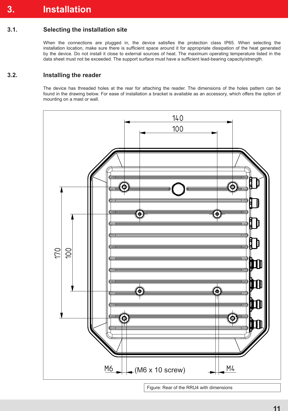
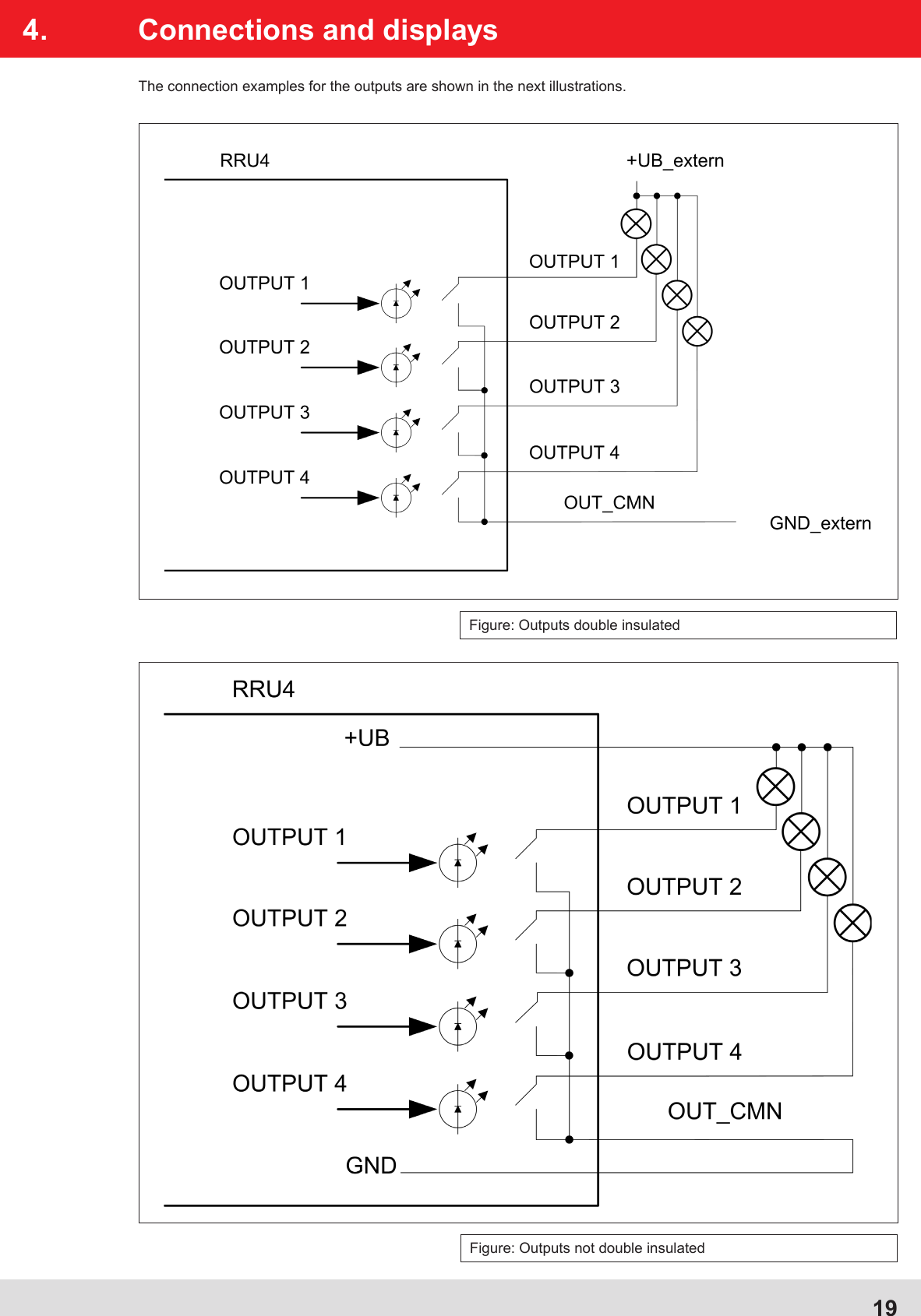
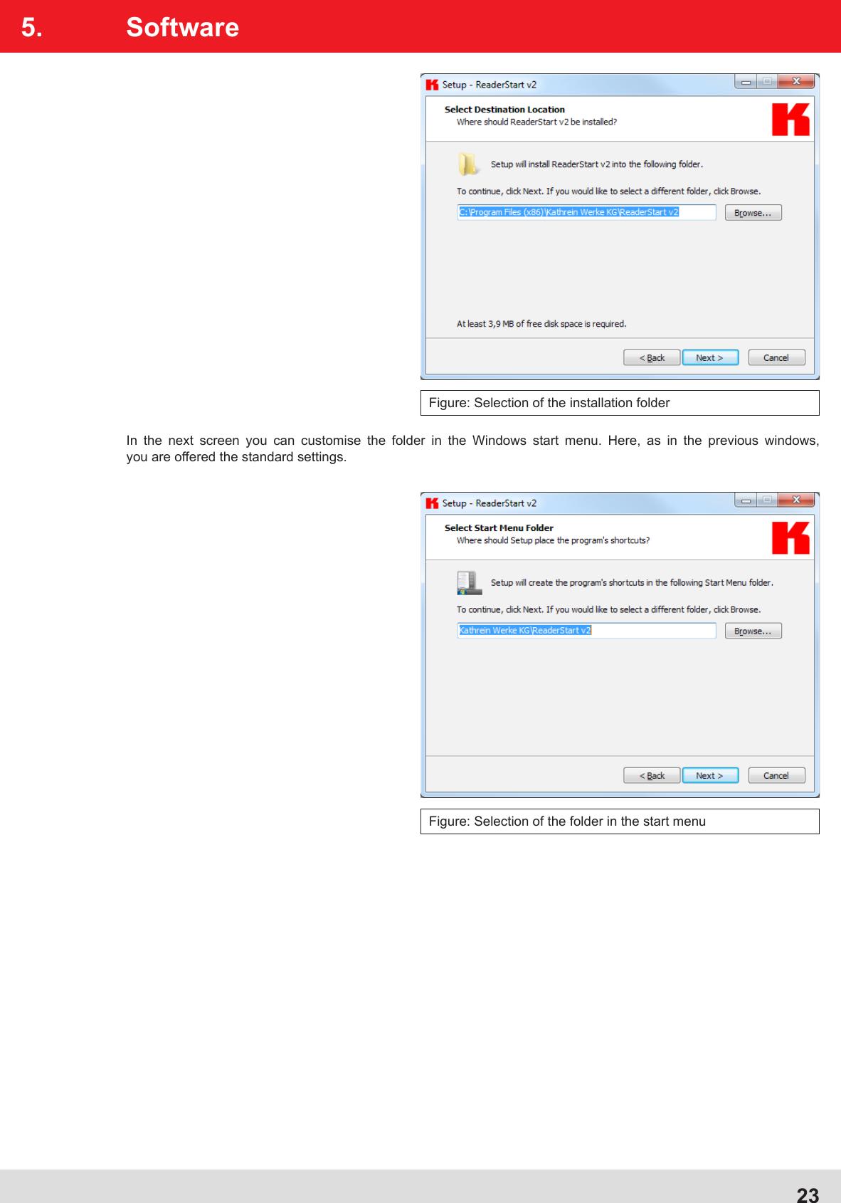
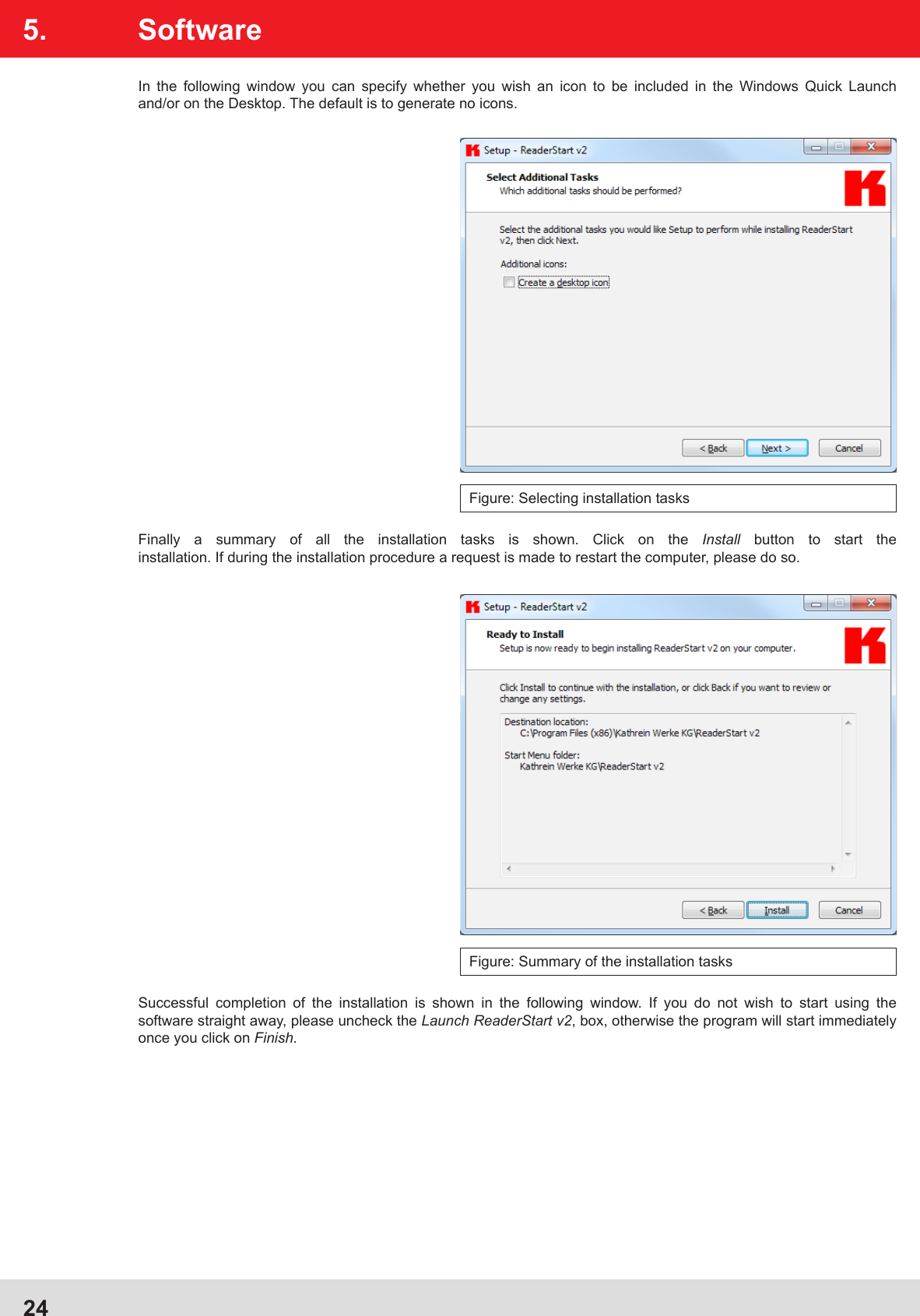
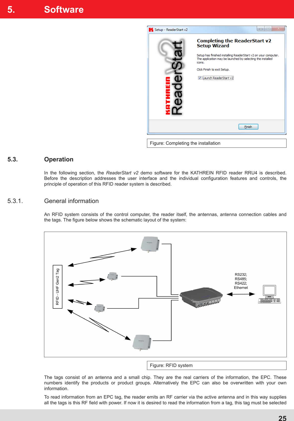
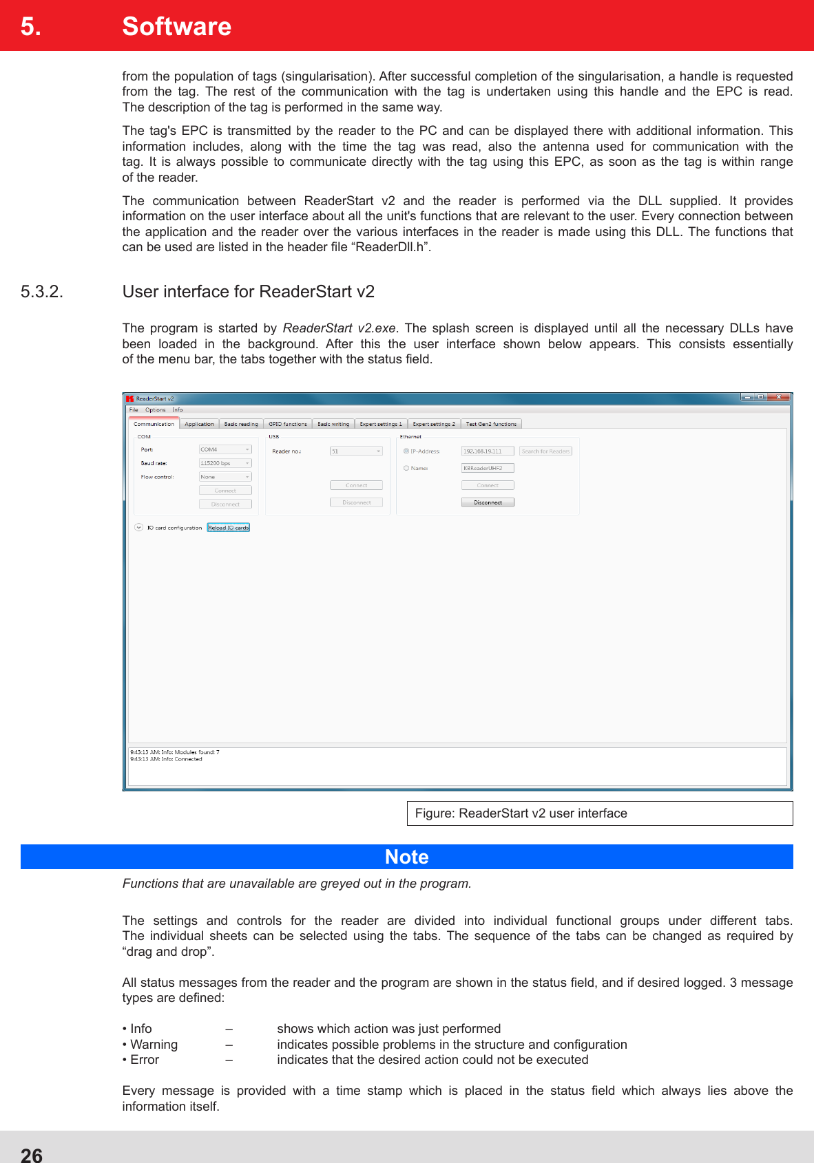
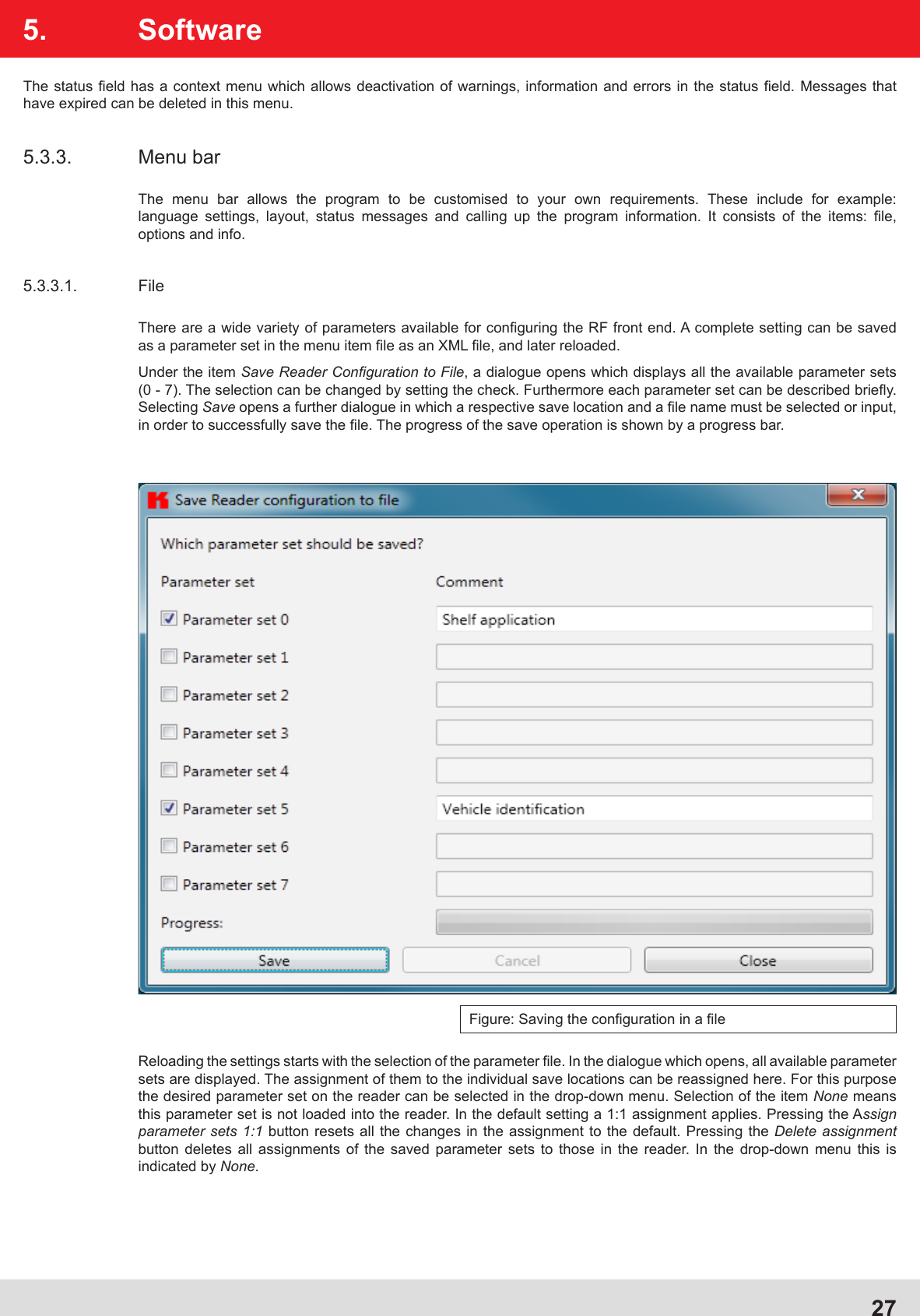
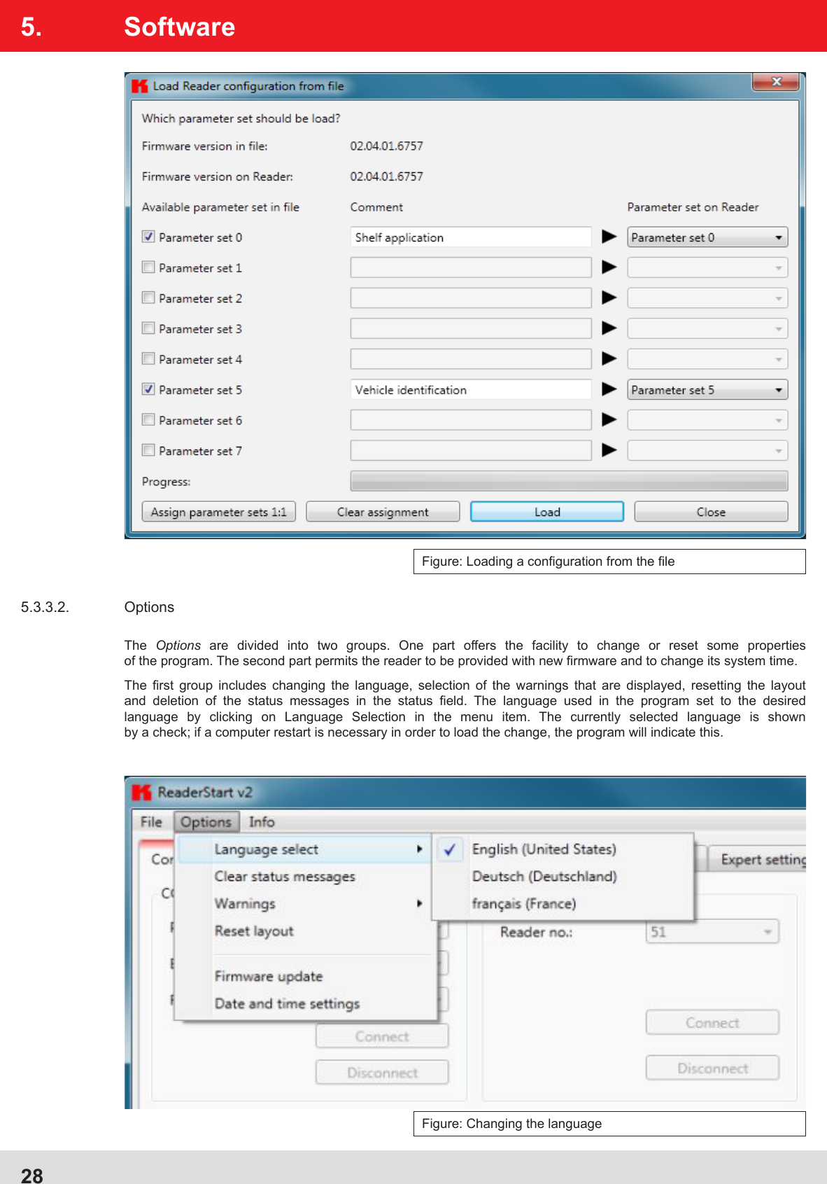
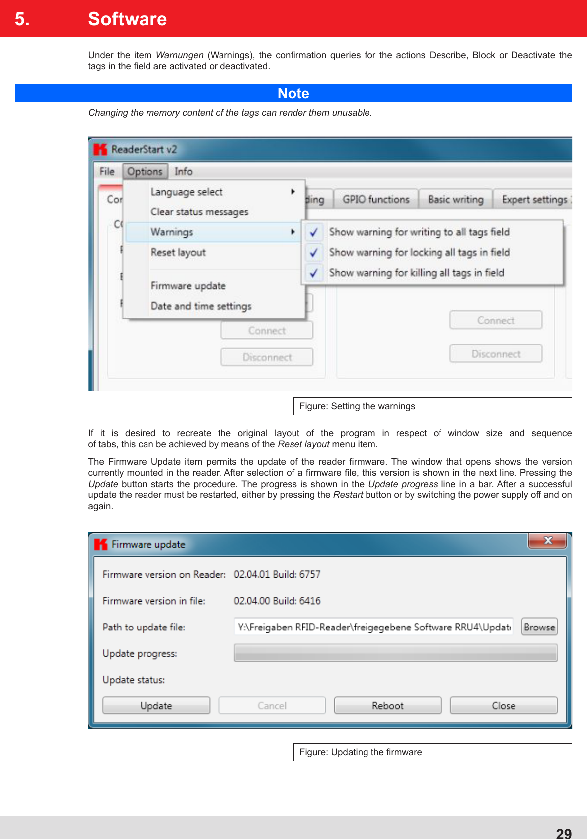
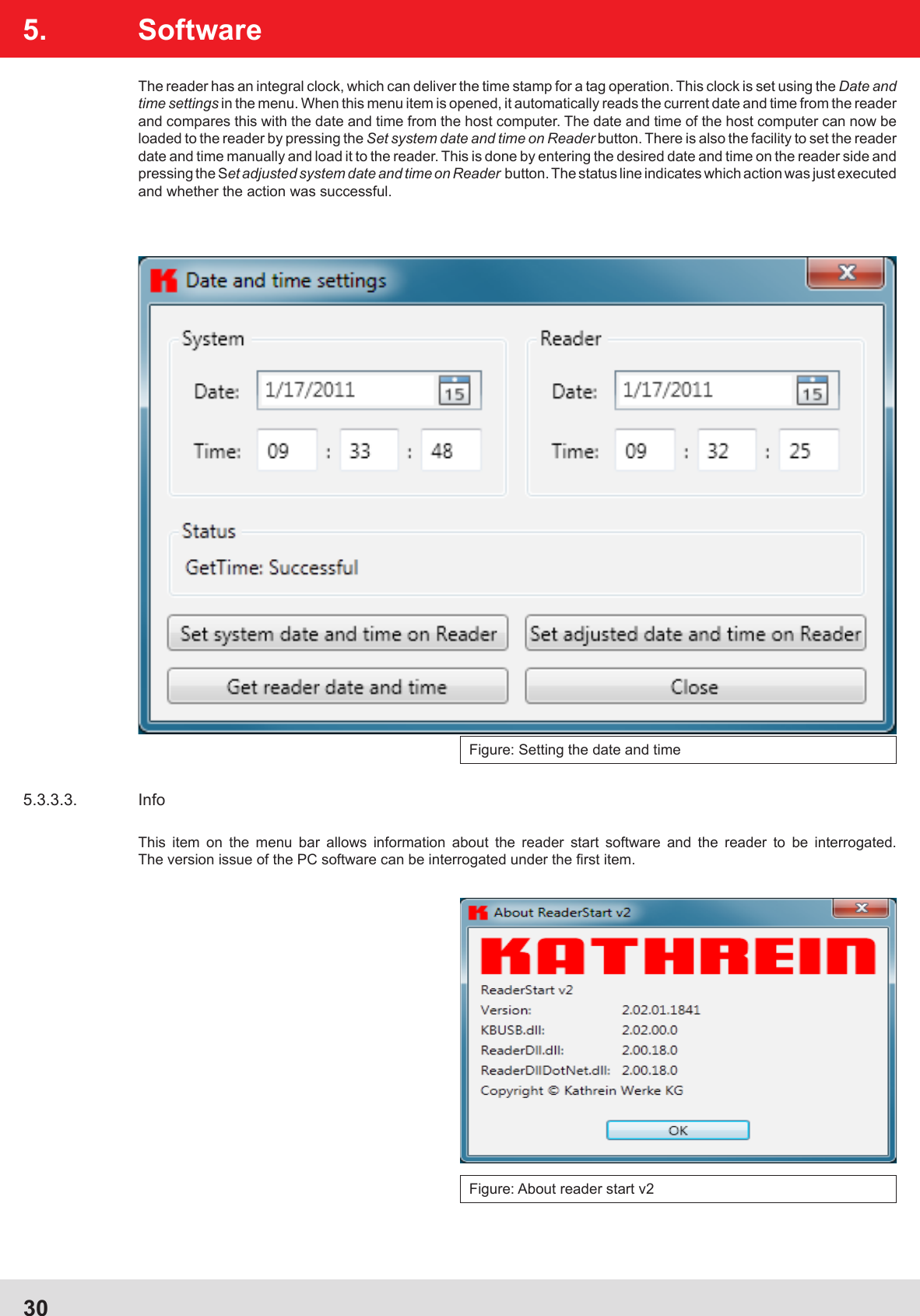
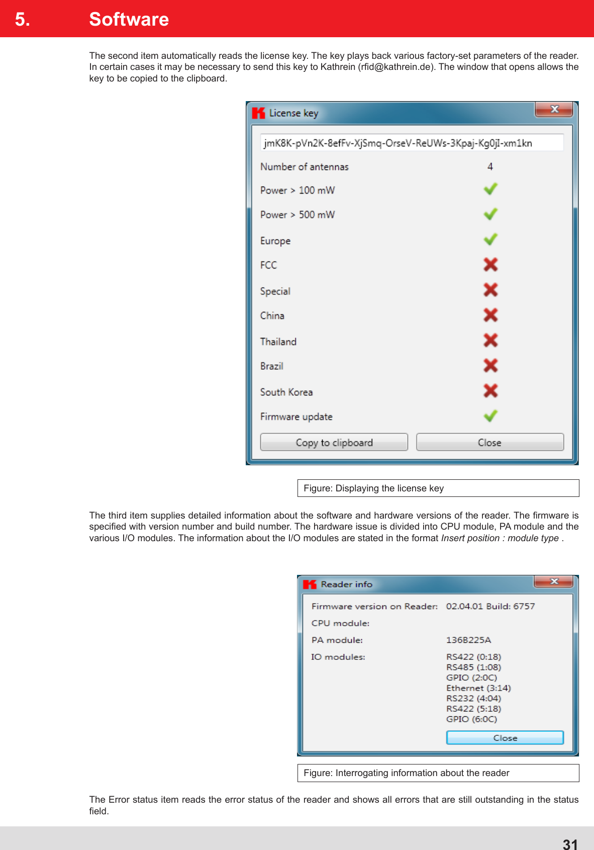
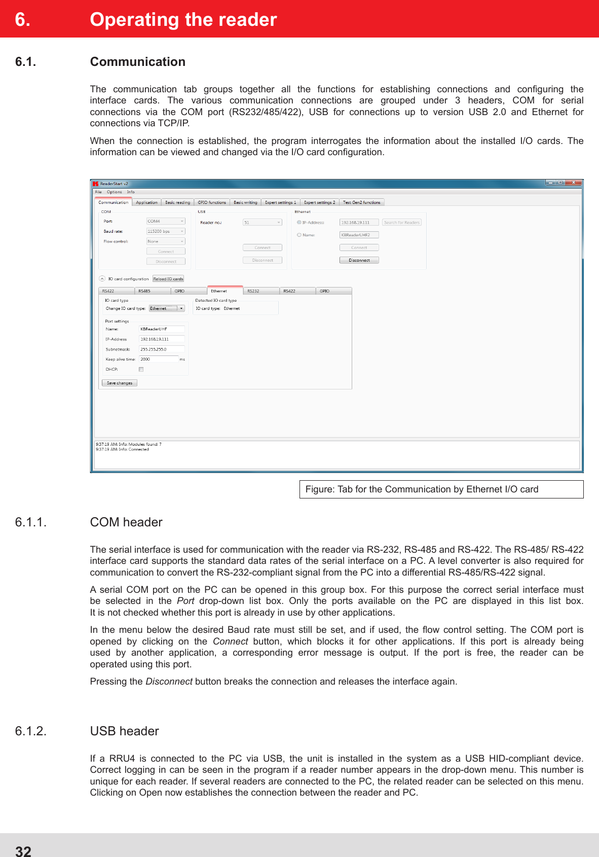
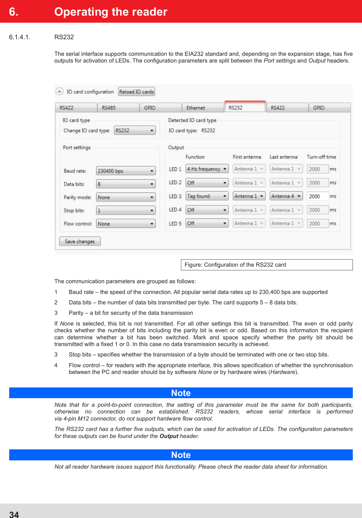
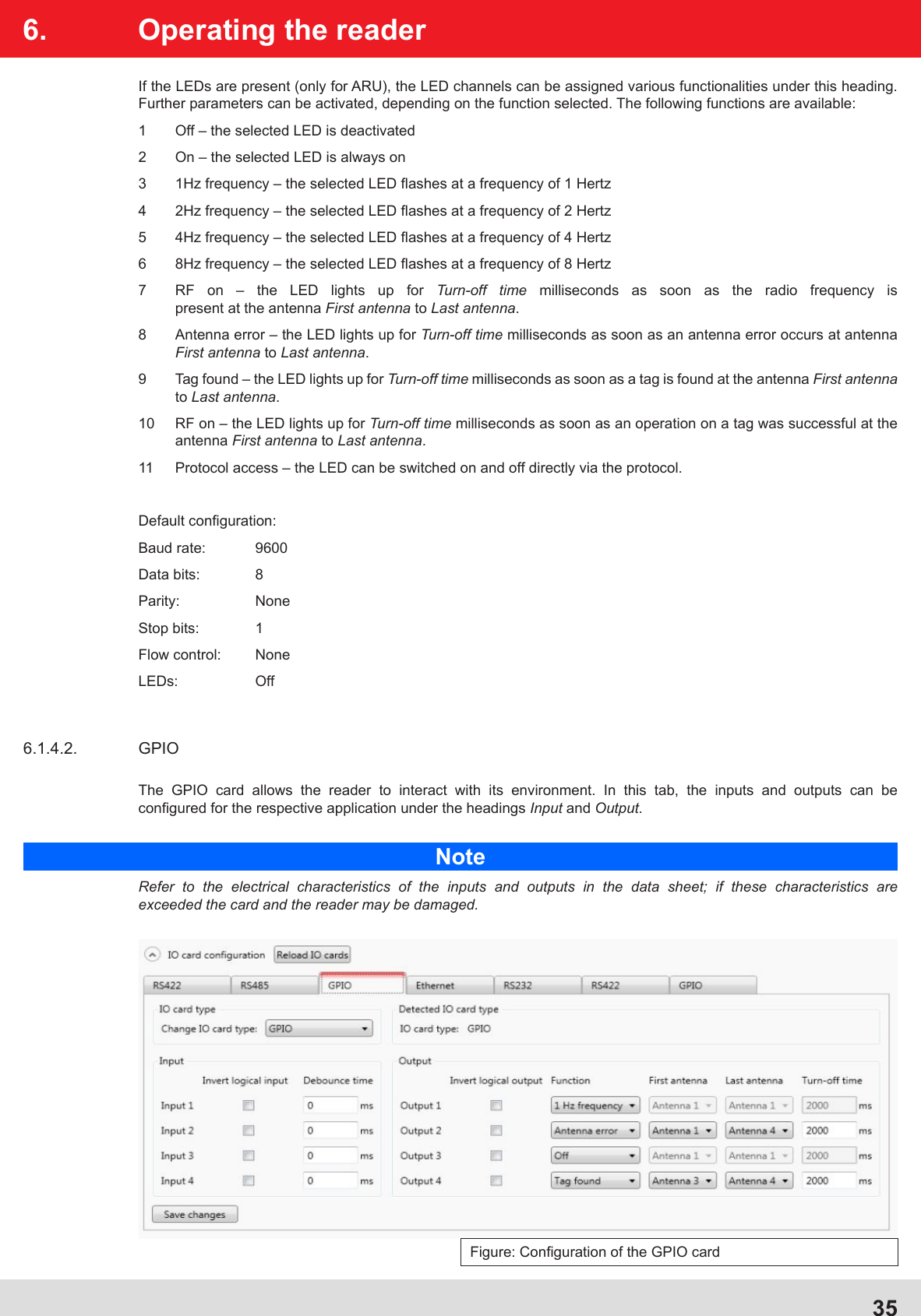
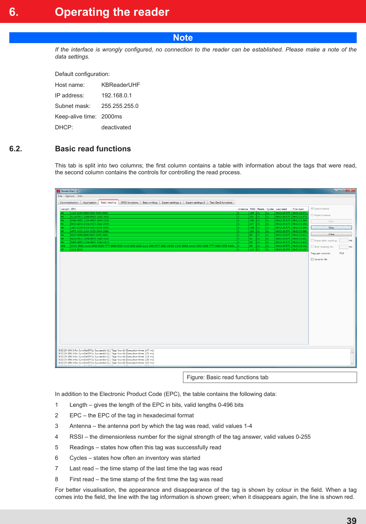
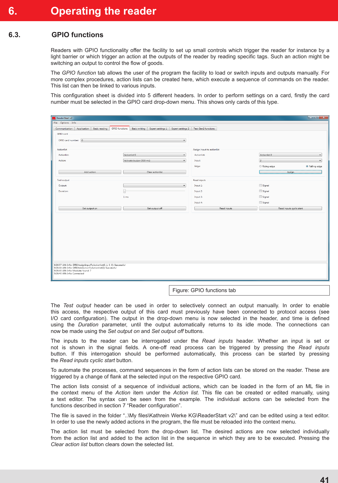
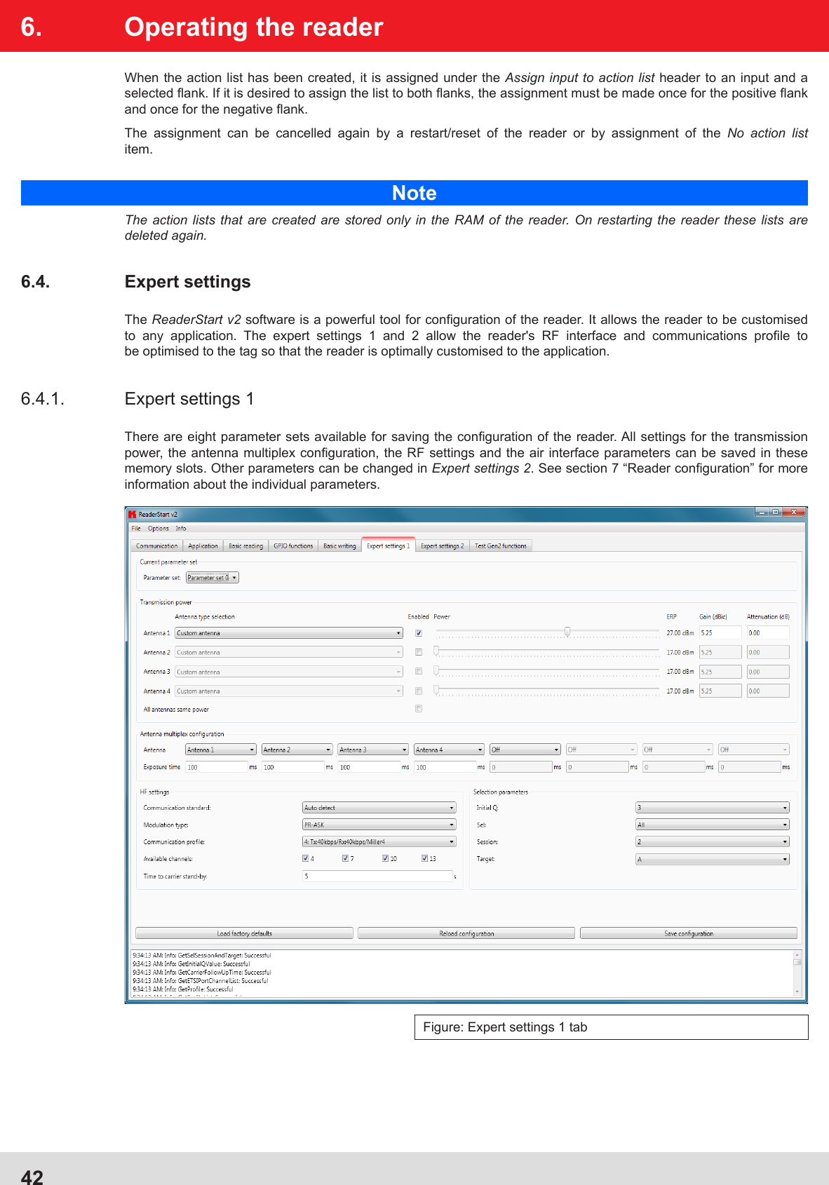
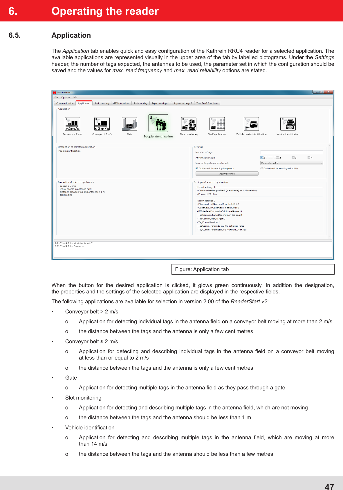
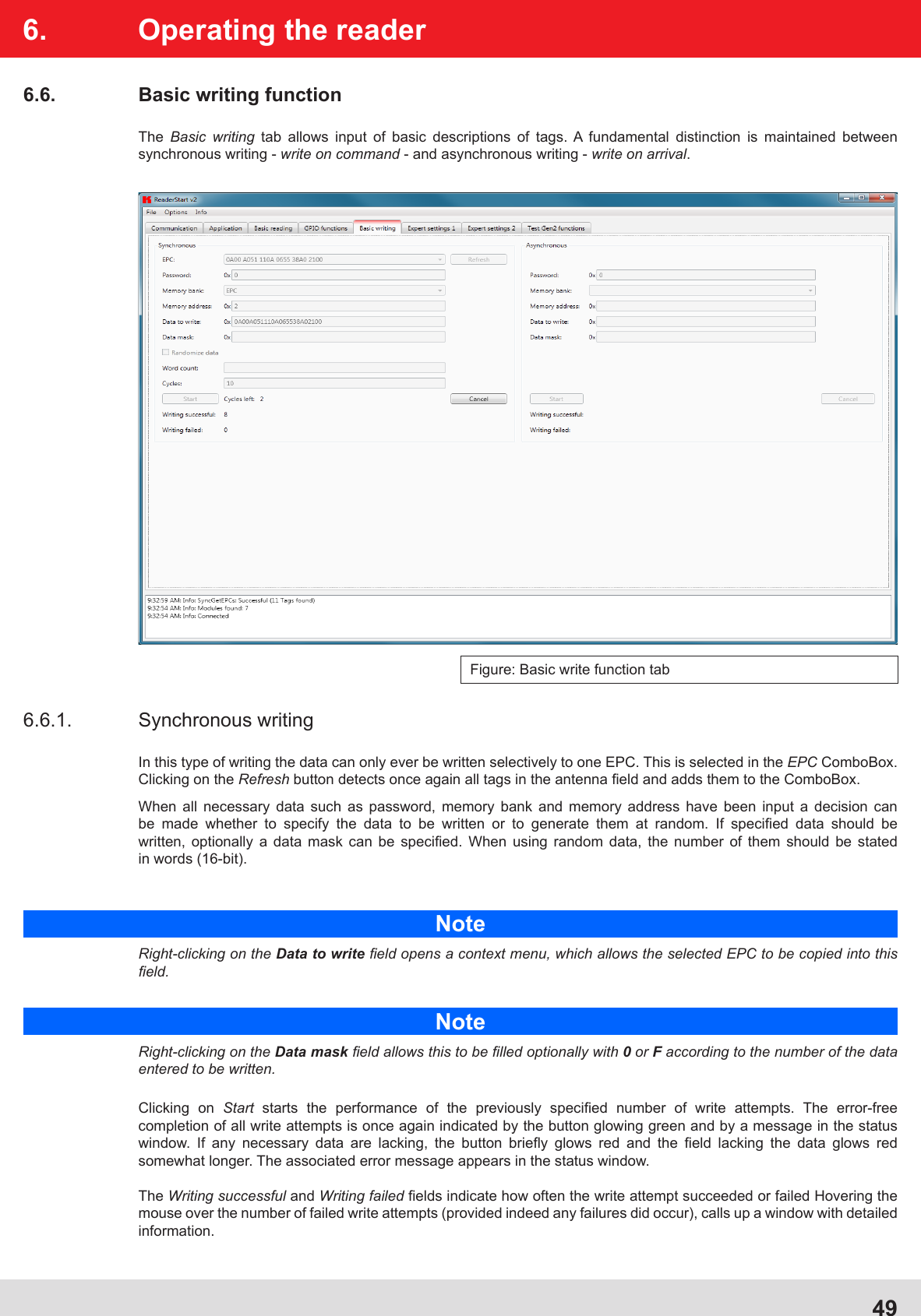
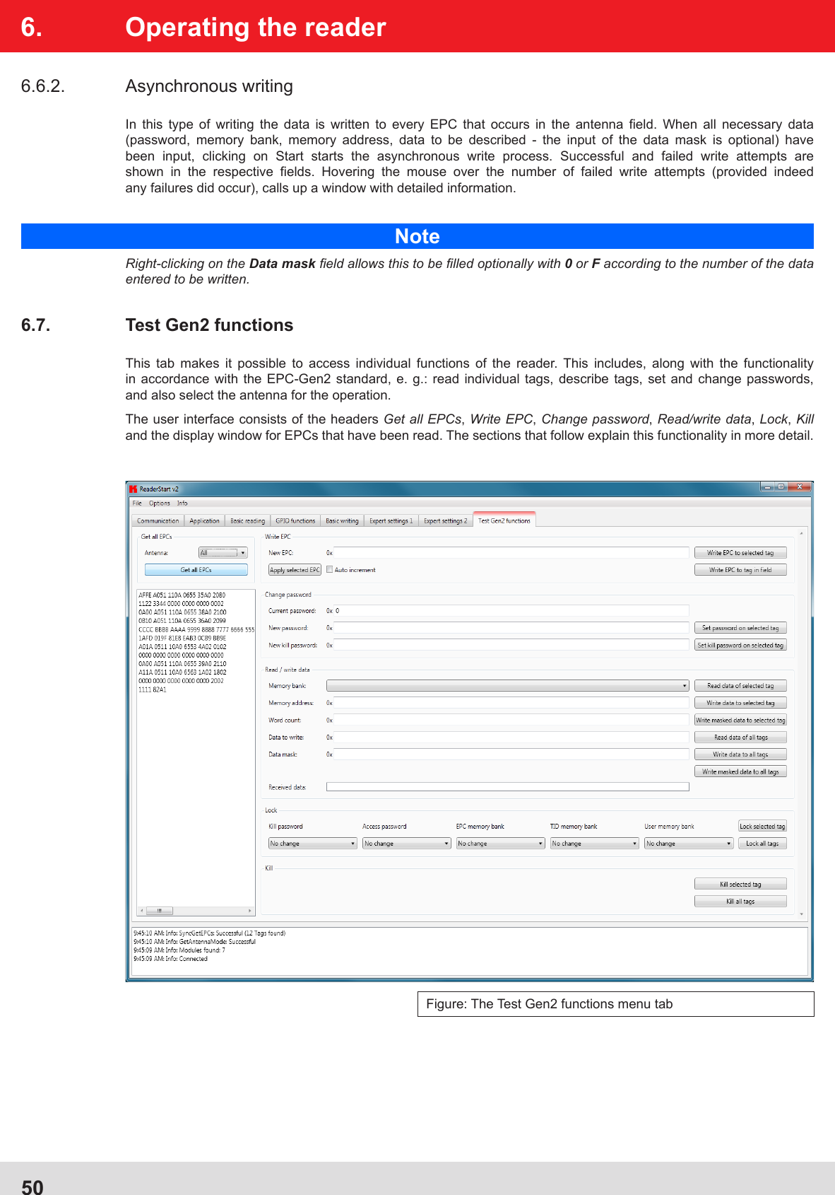
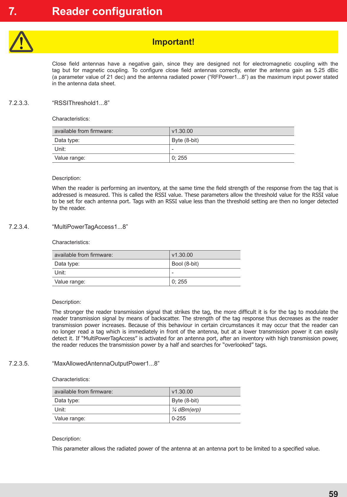
![687. Reader configuration7.2.5.3. “ObservedTimeoutCnt”Characteristics:available from fi rmware: v1.30.00Data type: Byte (8-bit)Unit: –Value range: 0-255Description:This confi guration parameter applies only to asynchronous protocol commands (“ASync...”). For the duration of an asynchronous command, the reader compiles a list of all the tags found within the antenna range. If a tag is present in the antenna range for multiple inventories, a “coming” message is generated for that tag and the message is sent to the higher level. If a tag is no longer detected during multiple inventories, a “going” message is generated and sent.This confi guration parameter specifi es the number of inventories where the tag is no longer detected, which then triggers the generation of a “going” message which is sent to the higher level.7.2.6. The confi guration group “Host communication” (“HostComm”)7.2.6.1. “ExtendedResultFlag”Characteristics:available from fi rmware: v1.30.00Data type: Byte (8-bit)Unit: –Value range: 0-15Description:This confi guration parameter allows specifi cation of which additional information on a tag should be sent when tag data are sent to the higher level. Every bit of the lower four bits that is set to “1” in this confi guration parameter causes the sending of certain additional information:Bit 0: Sending the antenna information (the antenna which detected the tag)Bit 1: Sending the RSSI value (fi eld strength information of the tag response)Bit 2: Sending the time stamp (the time when the tag was detected)Bit 3: Sending the protocol control word of the tag (PC, [XPC_W1, [XPC_W2]]; see also the “EPCglobal Class 1 Generation 2 UHF RFID” specifi cation V1.2.0 section 6.3.2.1.2 (page 38).)7.2.6.2. “AntennaIndependentOperation”Characteristics:available from fi rmware: v1.30.00Data type: Bool (8-bit)Unit: –Value range: 0; 255Description:This confi guration parameter allows differentiation between “antenna-dependent” (confi guration parameter deactivated) and “antenna-independent” (confi guration parameter activated) operation of the reader. This confi guration parameter is relevant to all asynchronous protocol commands (“ASync...”) and to the command “SyncBulkGetEPCs”. In the case of the specifi ed protocol commands the reader compares a tag which it has detected during an inventory with the tags listed on an internal list.](https://usermanual.wiki/KATHREIN-Sachsen/RRU4ETGU6/User-Guide-1533187-Page-68.png)