KATHREIN Sachsen RRU4ETGU6 UHF RFID Reader User Manual en Stand A indd
KATHREIN Sachsen GmbH UHF RFID Reader en Stand A indd
user manual
User manual English
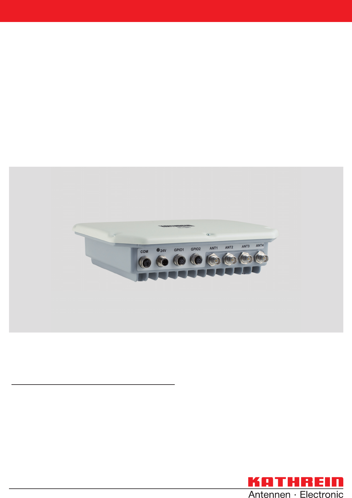
RRU4
RFID UHF READER
This manual applies to the following types:
Type: Order no.
RFID-UHF reader RRU4-RS4-E6 52010093
RFID-UHF reader RRU4-ETG-E6 52010094
RFID-UHF reader RRU4-RS4-U6 52010096
RFID-UHF reader RRU4-ETG-U6 52010097

2
Foreword and general information
The reproduction or distribution of this document or extracts from it in whatever form and by whatever means (electronic or mechanical)
for whatever purpose is permitted only with the prior written permission of Kathrein.
Kathrein accepts no liability for omissions or inaccuracies in this document or in relation to the provision or use of the information
contained in this document. Kathrein reserves the right to change the products described in this document and does not accept any
liability in relation to the application or usage of the products described in this manual.
This document and the information contained in it are proprietary information of Kathrein and should be treated as confi dential.
Kathrein provides this document to its customers in connection with contacts of sale for the products described therein. If the person
in possession of this document, being a legal or natural person, is not a contractual sales partner of Kathrein, or Kathrein has not
intended him by other means as the recipient of the document and the information contained therein, the person in possession is hereby
informed that the use of this document is unlawful and a violation of the rights of Kathrein.
Copyright notice
The information in this manual was correct at the time of editorial deadline.
We reserve the right however to make changes at any time and without prior notice.
This document was prepared for specialist personal who install, confi gure and place in operation the reader.
Scope
The information contained in this manual is intended for the support of the development process and as development guidance
for the customer. In addition this manual offers supporting information about the standards to be applied at the place of installation
and the relevant safety standards for installation and confi guration of the Kathrein reader.
General information
This manual contains information on the installation, confi guration, operation and maintenance of the reader. In addition it gives
detailed technical data in order better to familiarise the user with the features of the reader.
In order to ensure a long working life and fault-free operation, this manual should therefore be read carefully and all the instructions
and information contained in it should be complied with.
Warranty
Switching on the AC or DC power supply prior to connecting the LAN cable is considered incorrect installation. Any functional defect
arising as a result is excluded from the warranty/guarantee. Before installing or servicing the reader, the person concerned must
have read the manual and understood its contents. Kathrein accepts no liability if the customer fails to implement the precautions
listed here. In such cases, any claims under the warranty/guarantee are void.
Disposal instruction
Electronic equipment is not classed as household waste and must be disposed of properly in accordance with
Directive 2002/96/EC OF THE EUROPEAN PARLIAMENT AND OF THE COUNCIL of 27 January 2003 on used
electrical and electronic equipment.
At the end of its service life, take this device for disposal at a designated public collection point.
Used batteries are special waste!
Do not put used batteries into your domestic waste; instead take them to a collection point for used batteries!

3
List of Contents
Foreword and general information 2
List of Contents 3
1. Safety instructions/information 6
2. Introduction 9
2.1. The reader 9
2.2. Further reference material 9
2.3. Scope of supply 9
2.4. Accessories 9
3. Installation 11
3.1. Selecting the installation site 11
3.2. Installing the reader 11
4. Connections and displays 12
4.1. Power supply 12
4.2. Ethernet port 13
4.3. RS422/485 connection 13
4.4. RS232 connection 13
4.5. UART transmission (RS232, RS422, RS485 or similar) 14
4.5.1. Bit transmission layer (physical layer) 14
4.5.2. Data link layer 14
4.5.2.1. Structure of a frame 14
4.5.2.2. Start code and synchronisation 14
4.5.2.3. Status byte 14
4.5.2.4. Frame number 15
4.5.2.5. User data 15
4.5.2.6. Checksum 15
4.5.3. Network layer 15
4.5.4. Transport layer, session layer, presentation layer 15
4.5.5. Application layer 15
4.6. Ethernet transmission 16
4.6.1. Frame structure 16
4.6.2. Port 16
4.6.3. Example 16
4.7. Digital inputs and outputs 17
4.8. Antenna Connection 20
4.9. LED 20
4.10. Buzzer 20
5. Software 21
5.1. System requirements 21

4
List of Contents
5.2. Installation 21
5.3. Operation 25
5.3.1. General information 25
5.3.2. User interface for ReaderStart v2 26
5.3.3. Menu bar 27
5.3.3.1. File 27
5.3.3.2. Options 28
5.3.3.3. Info 30
6. Operating the reader 32
6.1. Communication 32
6.1.1. COM header 32
6.1.2. USB header 32
6.1.3. Ethernet header 33
6.1.4. I/O card configuration 33
6.1.4.1. RS232 34
6.1.4.2. GPIO 35
6.1.4.3. RS485 37
6.1.4.4. Ethernet 38
6.2. Basic read functions 39
6.2.1. Synchronous mode 40
6.2.2. Asynchronous mode 40
6.3. GPIO functions 41
6.4. Expert settings 42
6.4.1. Expert settings 1 42
6.4.1.1. Transmission power 43
6.4.1.2. Antenna multiplex configuration 45
6.4.1.3. RF settings 45
6.4.1.4. Selection parameters 45
6.4.2. Expert settings 2 46
6.5. Application 47
6.6. Basic write function 49
6.6.1. Synchronous writing 49
6.6.2. Asynchronous writing 50
6.7. Test Gen2 functions 50
6.7.1. Read all EPCs 51
6.7.2. Write EPC 51
6.7.3. Change password 51
6.7.4. Read/write data 52
6.7.5. Block 52
6.7.6. Deactivation 53
7. Reader configuration 54
7.1. Introduction 54
7.1.1. Structure of the configuration IDs 54
7.1.2. The parameter sets 54
7.2. Description of the configuration parameters of the RRU4 reader system 55
7.2.1. The “Global” configuration group 55
7.2.1.1. “DefaultParamset” 55
7.2.2. The configuration group “RFInterface” 55

5
7.2.2.1. “RFPower1...8” 55
7.2.2.2. “TimeToPowerOff” 56
7.2.2.3. “ModulationType” 56
7.2.2.4. “MultiplexingAntennaport1...8” 57
7.2.3. “MultiplexingExposureTime1...8” 58
7.2.3.1. “CableLoss1...8” 58
7.2.3.2. “AntennaGain1...8” 58
7.2.3.3. “RSSIThreshold1...8” 59
7.2.3.4. “MultiPowerTagAccess1...8” 59
7.2.3.5. “MaxAllowedAntennaOutputPower1...8” 59
7.2.3.6. “EnableRSSIThresholdAtSpecificCmds” 60
7.2.3.7. “FlashWriteAdditionalPower” 60
7.2.4. The configuration group “Tag communication” (“TagComm”) 60
7.2.4.1. “UsePilottone” 60
7.2.4.2. “InitialQ” 61
7.2.4.3. “Session” 61
7.2.4.4. “MaxErrors” 62
7.2.4.5. “CommunicationProfile” 62
7.2.4.6. “CommStandard” 62
7.2.4.7. “IntelligentWrite” 63
7.2.4.8. “VerifyWrite” 63
7.2.4.9. “QueryTarget” 64
7.2.4.10. “QuerySel” 64
7.2.4.11. “ForcePowerOffAfterEPCWrite” 65
7.2.4.12. “TransmitGetEPCsPreSelect” 65
7.2.4.13. “TransmitSelectIfNoFilterIsOn” 66
7.2.4.14. “NumberOfEPCWords” 66
7.2.4.15. “UseBlockWrite” 66
7.2.4.16. “DisableReceivingNXPReadProtectedTags” 67
7.2.5. The configuration group “ObservedList” 67
7.2.5.1. “GlimpsedTimeoutCnt” 67
7.2.5.2. “ObservedThresholdCnt” 67
7.2.5.3. “ObservedTimeoutCnt” 68
7.2.6. The configuration group “Host communication” (“HostComm”) 68
7.2.6.1. “ExtendedResultFlag” 68
7.2.6.2. “AntennaIndependentOperation” 68
7.2.6.3. “ASyncAdditionalRSSIDataDeliveryDelta” 69
7.2.6.4. “UseMillisecondsAsTimestamp” 69
7.2.7. The configuration group “ETSI” 70
7.2.7.1. “PortChannelListGlobalValue1...16” 70
7.2.7.3. “ChannelSwitchingMode” 70
7.2.7.4. “PowerCheckOverAllAllowedChannels” 71
7.2.8. The configuration group “communication standard” (“CommStandard”) 71
7.2.8.1. “CenterFreqCH0” 72
7.2.8.2. “ChannelWidth” 72
7.2.8.3. “MaxChannelTime” 72
7.2.8.4. “MinChannelWaitTime” 73
7.2.8.5. “FirstChannel” 73
7.2.8.6. “LastChannel” 73
8. Reference literature 74
List of Contents
6
Key
Caution Indicates a potentially dangerous situation which, if disregarded, can lead to injuries ranging
from minor to severe and/or damage to the unit.
Note Information intended to make a specifi c topic easier to understand and/or enable optimal use
of the unit functions.
Important!
Before starting installation work or replacing the unit, the accompanying manual must be read carefully and its
contents understood.
The detailed information in the data sheets and in this manual must be complied with carefully during installation and
operation of the reader!
The installation team must be properly qualifi ed and familiar with the safety regulations applicable in the country
concerned.
Connection, installation and maintenance work, as well as all other work on the unit, may only be carried out by
properly qualifi ed and trained employees.
The unit may only be used for the purpose intended by the manufacturer.
Unauthorized changes to the unit and the use of spare parts and peripheral devices which are not sold or
recommended by the manufacturer can result in fi res, electric shocks and injuries. Such actions therefore result in
exclusion of liability and make the manufacturer’s warranty/guarantee null and void.
The applicable version of the manufacturer’s warranty is that which was valid at the time of purchase. We accept
no liability for unsuitable manual or automatic adjustments made to the unit's parameters and inappropriate use of
the unit.
Repairs may only be undertaken by personnel authorised to perform them. Opening or attempting to repair the
unit makes all guarantee/warranty claims null and void! Improper work on the unit may jeopardise electrical safety.
The manufacturer is not liable for accidents caused by the user opening the unit!
When carrying out work on the unit, the valid safety regulations must be complied with.
Supply voltage
Make sure that the mains cable (power supply cable) is not damaged. If the mains cable is damaged, the device
must not be used. Instead it must be disconnected from the mains and repaired by a qualifi ed technician. Use only
the power supply unit supplied!
Risk of fatal injury due to electric shock!
The device may be operated only at the stated supply voltage (see the rear of the device or external power supply
unit)!
If the supply voltage is too high, there is a risk of fi re!
General safety notes
1. Safety instructions/information
Important!


8
Note
Following corresponding tests, it has been ascertained that this unit adheres to the limit values for class B digital
units in accordance with part 15 of the FCC regulations. These limit values are intended to provide private user's
systems with appropriate protection against harmful radio interference. This unit generates and uses energy
in the radio frequency range and is also able to radiate this; if it is not installed and used in accordance with the
regulations, the unit may cause harmful radio communication interference. However, there is no guarantee that
interference will not occur in a specifi c system. If this unit causes harmful radio or television reception interference,
which can be ascertained by switching the unit on and off, we recommend that the user attempts to rectify this
interference via one or more of the following measures:
- Realign the receive antenna or change its position.
- Increase the distance between the unit and the receiver.
- Plug the unit into a socket in a current circuit other than that to which the receiver is connected.
- Seek advice from the retailer or an experienced radio/television technician.
1. Safety instructions/information
Important!/Attention !
This equipment complies with IC RSS-102 radiation exposure limits set forth for an uncontrolled environment.
This equipment should be installed and operated with minimum distance 20 cm between the radiator & your body.
Cet équipement est conforme aux limites d‘exposition aux rayonnements IC établies pour un environnement non con-
trôlé. Cetéquipement doit être installé et utilisé avec un minimum de 20 cm de distance entre la source de rayonnement
et votre corps.
IC Radiation Exposure Statement/Déclaration d‘exposition aux radiations
included in this list, having a gain greater than the maximum gain indicated for that type, are strictly prohibited for use
with this device.
Conformément à la réglementation d‘Industrie Canada, le présent émetteur radio peut fonctionner avec une antenne
d‘un type et d‘un gain maximal (ou inférieur) approuvé pour l‘émetteur par Industrie Canada. Dans le but de réduire les
risques de brouillage radioélectrique à l‘intention des autres utilisateurs, il faut choisir le type d‘antenne et son gain de
sorte que la puissance isotrope rayonnée équivalente (p.i.r.e.) ne dépasse pas l‘intensité nécessaire à l‘établissement
d‘une communication satisfaisante.
Le présent appareil est conforme aux CNR d‘Industrie Canada applicables aux appareils radio exempts de licence.
L‘exploitation est autorisée aux deux conditions suivantes : (1) l‘appareil ne doit pas produire de brouillage, et (2)
l‘utilisateur de l‘appareil doit accepter tout brouillage radioélectrique subi, même si le brouillage est susceptible d‘en
compromettre le fonctionnement.
Avis de conformité insérés dans le manuel d‘utilisation des appareils radio exempts de licence
Le présent appareil est conforme aux CNR d‘Industrie Canada applicables aux appareils radio exempts de licence.
L‘exploitation est autorisée aux deux conditions suivantes : (1) l‘appareil ne doit pas produire de brouillage, et (2)
l‘utilisateur de l‘appareil doit accepter tout brouillage radioélectrique subi, même si le brouillage est susceptible d‘en
compromettre le fonctionnement.
Modifi cations or conversions which are carried out on this unit without the express permission of Kathrein
may invalidate the FCC permit for the operation of this unit.
Note
To meet part 15 of the FCC regulations in the United States, the system must be properly installed to guarantee
adherence to the certifi cation regulations according to part 15. The operator and the specialist company which carries
out installation are responsible for ensuring that only certifi ed systems are used in the United States. Use of this
system in any other combination (e.g. several antennas which transmit the same information in the same location)
is expressly prohibited.
Note regarding proper installation:

9
2. Introduction
2.1. The reader
The Kathrein RFID (Radio Frequency Identifi cation) reader RRU4 is a multi-protocol-capable device for reading
active and passive RFID tags in the frequency range from 865 to 868 MHz for Europe and 902 to 928 MHz for
the American market. As supplied the unit can read and write tags in accordance with the EPC-Gen2 standard.
Additional protocols can be loaded using software updates.
The reader operates using the frequency skipping process, so as to avoid faults and interference between readers.
Readers change their transmission channel in a random or pre-programmed sequence.
For the ETSI area this means that in accordance with EN 302208 V1.2.1 the reader must pause its transmission for
100ms (and change its frequency) after it has transmitted continuously for 4s.
Within the FCC area this procedure is mandatory. The reader changes its transmission frequency randomly, with equal
distribution across the 50 available channels.
The device has a maximum of four external antenna ports for connection of the transmission/reception antennas for
communication with RFID tags.
For integration into a variety of infrastructures, the device has different communication interfaces depending on the
variant. The power supply is provided by a 4-pin M12 panel connector in A coding.
2.2. Further reference material
In order to confi gure the reader correctly and adapt it to the respective application, detailed knowledge of the
EPCGlobal standards of GS1 is necessary ((B)). This standard describes the principle of operation of the interface
between the tag and reader.
The parameters available for the confi guration of the reader are described from section 7 “Reader Confi guration” of
this manual.
The reader is controlled via the Kathrein-Burgstädt Reader Protocol (KBRP). The current version of the KBRP
specifi cation document ((A)) includes a detailed description of the protocol.
Note
The versions of the documents must match the software version of the reader. The CD supplied contains the current
documents for the reader fi rmware supplied.
2.3. Scope of supply
The contents of the packaging consist of the following items:
- 1 RRU4 (grey casing)
- 1 CD with demo software, programming examples, DLL and operating instructions
10
2. Introduction
- Connection cable sets (without antenna cables)
Designation Order no. Consisting of
cabling set RRU4 RS4 52010125 Power supply cable M12/free end, length 2 m; RS 422/485 interface cable
M12/free end, length 2 m; 2 x GPIO cable M12/free end, length 2 m)
cabling set RRU4 ETG 52010126 Power supply cable M12/open, length 2 m; Ethernet interface cable
M12/RJ 45 socket, length 2 m; 2 x GPIO cable M12/free, length 2 m)
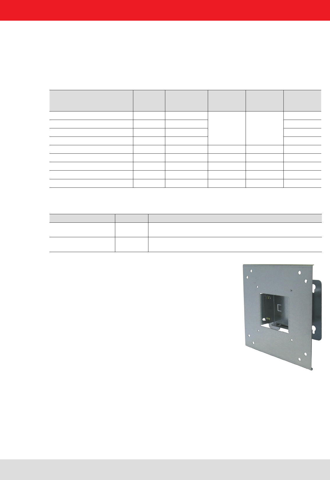
- Mast and wall clamp, BN 52010128
Wall/mast clamp for installing RFID antennas and RRU4/ARU4
readers (up to 6.0 kg total weight).
- Protective cap set, BN 52010127
Accessories set for RRU4/ARU4 reader with screw-on protective caps for 3x antenna input (R-TNC) and
2x digital connection (M12)
2.4. Accessories
The following accessories are available for the reader (if you have questions about the accessories, please contact
our Sales Offi ce):
- Antennas: For use with UHF-RFID antennas; we recommend the Kathrein antenna types ULORA, LORA,
MIRA, WIRA. These antenna types are available for all frequency ranges.
- Antenna cable
Designation
(all cables listed:
IP54 standard)
Order no. 50-Ω cable
type Connector 1 Connector 2 Length (cm)
Cable 1 m, TNC-TNC(rev) 52010051 RG058-PE
TNC(f)-rev TNC(m)
100
Cable 2 m, TNC-TNC(rev) 52010052 RG058-PE 200
Cable 3 m, TNC-TNC(rev) 52010053 RG058-PE 300
Cable 6 m, TNC-TNC(rev) 52010054 RG058-PE 600
Cable 1 m, N-TNC(rev) 52010055 RG058-PE TNC(f)-rev N (m) 100
Cable 2 m, N-TNC(rev) 52010056 RG058-PE 200
Cable 3 m, N-TNC(rev) 52010057 RG058-PE 300
Cable 6 m, N-TNC(rev) 52010058 RG058-PE 600
11
3. Installation
3.1. Selecting the installation site
When the connections are plugged in, the device satisfi es the protection class IP65. When selecting the
installation location, make sure there is suffi cient space around it for appropriate dissipation of the heat generated
by the device. Do not install it close to external sources of heat. The maximum operating temperature listed in the
data sheet must not be exceeded. The support surface must have a suffi cient lead-bearing capacity/strength.
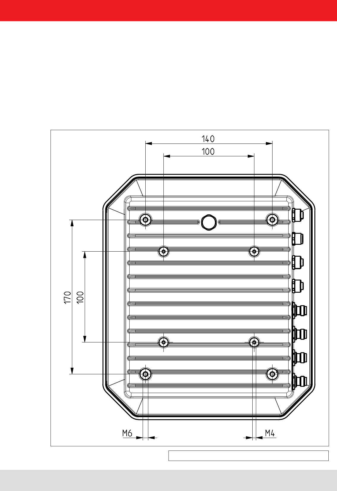
3.2. Installing the reader
The device has threaded holes at the rear for attaching the reader. The dimensions of the holes pattern can be
found in the drawing below. For ease of installation a bracket is available as an accessory, which offers the option of
mounting on a mast or wall.
Figure: Rear of the RRU4 with dimensions
(M6 x 10 screw)
12
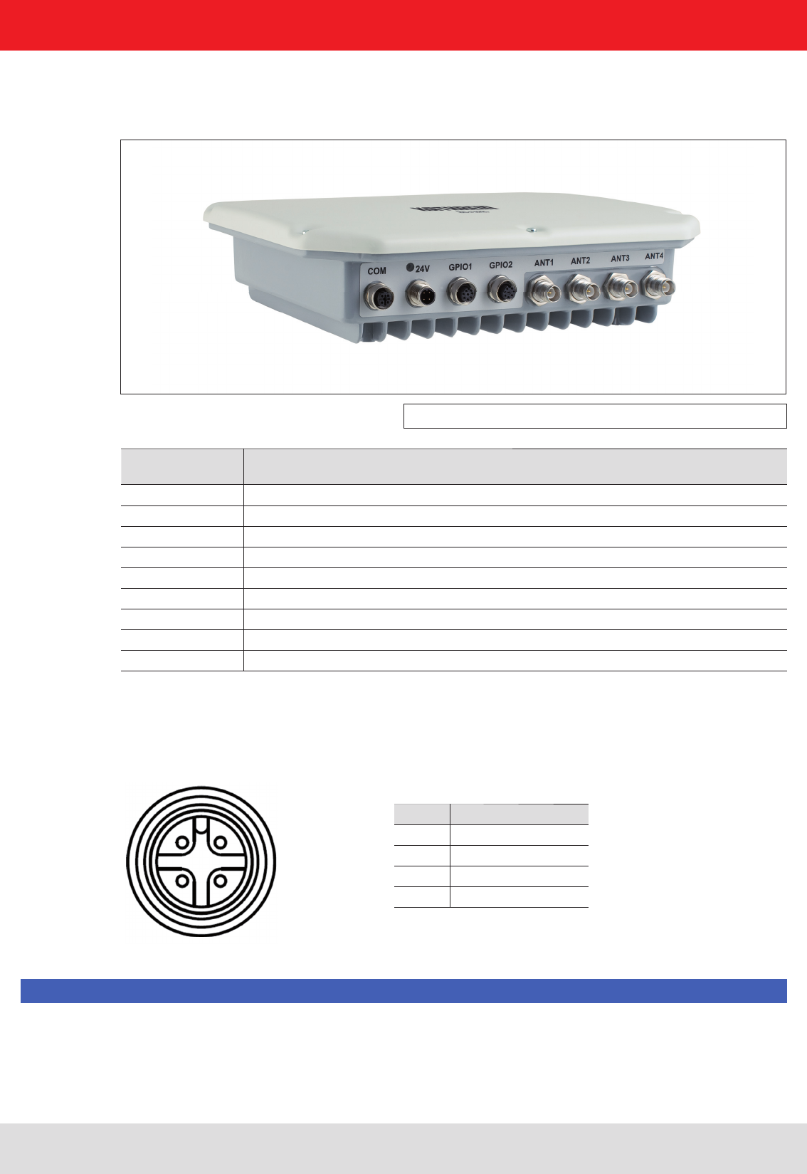
4. Connections and displays
Depending of the device variant, the reader has various connection options. The illustration below shows an
RRU4 standard reader with all its connection options. Details of the connections and the pin assignments of plugs
and sockets are provided in the following pages.
Figure: General view of the RRU4
Sockets, from
left to right Description
1 Communication connection: M12 (depending on the device variant)
2 Power supply connection: M12 male, 4-pin, A-coded
3 GPIO connection 1: M12 female, 8-pin, A-coded
4 GPIO connection 2: M12 female, 8-pin, A-coded
5 Antenna connection 1: R-TNC 50 Ohm
6 Antenna connection 2: R-TNC 50 Ohm
7 Antenna connection 3: R-TNC 50 Ohm
8 Antenna connection 4: R-TNC 50 Ohm
Status indicators: 3 coloured LEDs (red, green, orange)
2 1
3 4
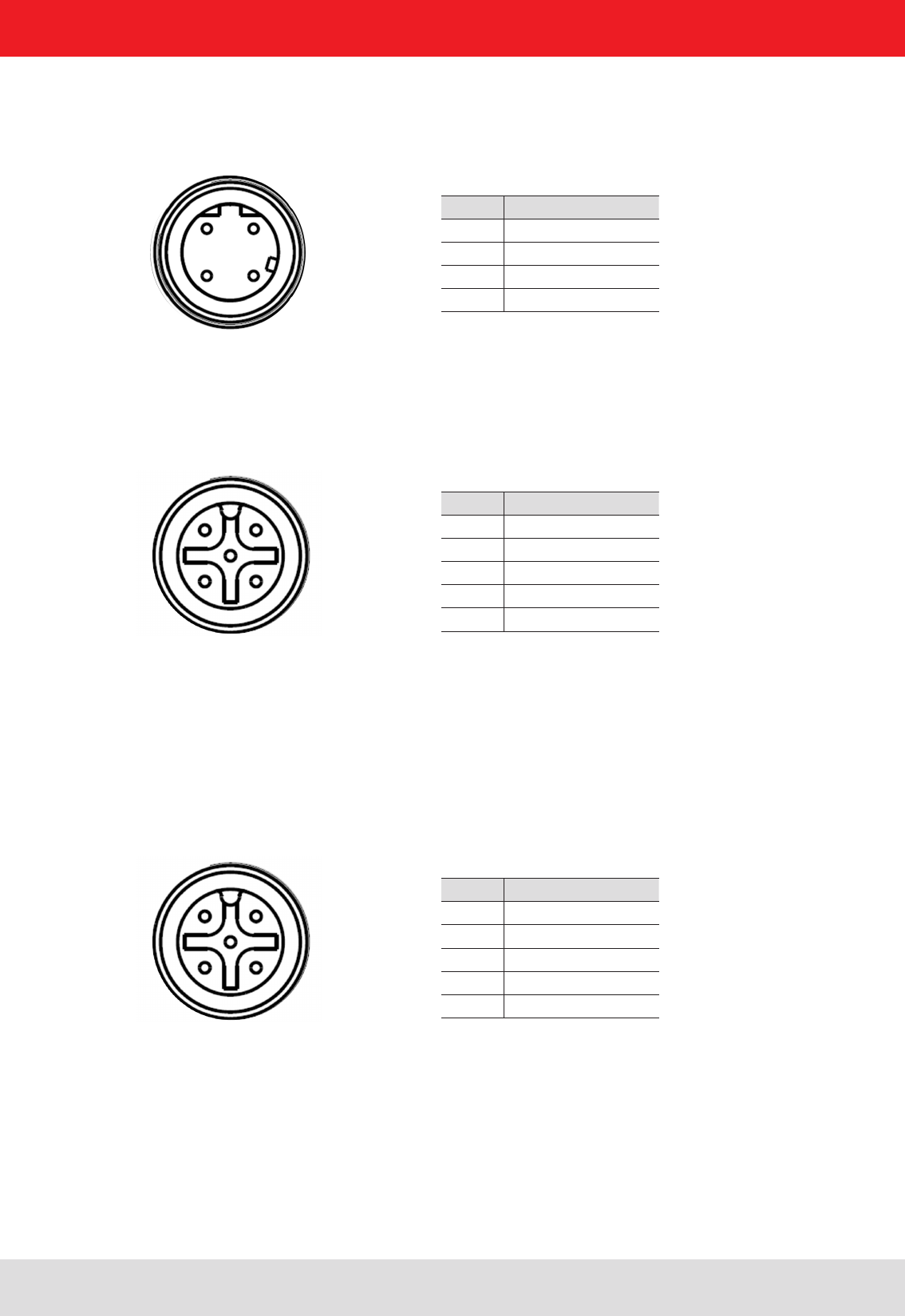
4.1. Power supply
The power supply is arranged as a four-pin round-pin plug with and M12 connection thread in A-coding.
PIN Assignment
1 +24 V DC
2
3 GND
4
For operating this device only LPS (Limited Power Source) or NEC class 2 classifi ed power supply units are approved!
That means the power of the power supply unit may not exceed 100 W on the secondary side.
Note
13
4. Connections and displays
4.2. Ethernet port
This data interface is arranged as a 4-pin M12 socket with D-coding. Only shielded cables may be used.
PIN Assignment
1 TD+
2 RD+
3 TD-
4 RD-
1 2
4 3
4.3. RS422/485 connection
This interface is arranged as a 5-pin M12 socket with A-coding. Only shielded cables may be used.
PIN Assignment
1 RxD+
2 RxD-
3 TxD+
4 TxD-
5 GND
1 2
4 3
5 central pin
The interface card of the reader is equipped with a combined RS485/RS422 interface. The changeover between
RS485 and RS422 is performed using the confi guration tool. For operation as RS422, the RS485 cables
are connected to RX.
4.4. RS232 connection
This interface is also arranged as a 5-pin M12 socket with A-coding. Only shielded cables may be used.
PIN Assignment
1 CTS
2 RxD
3RTS
4 TxD
5 GND
1 2
4 3
5 central pin

14
4. Connections and displays
4.5. UART transmission (RS232, RS422, RS485 or similar)
4.5.1. Bit transmission layer (physical layer)
A full or half-duplex connection such as RS232, RS422 or RS485 is used for the physical layer.
4.5.2. Data link layer
Transmission is in frames and blocks. A block comprises a maximum of 256 frames. A frame comprises a
maximum of 256 bytes, of which a maximum of 250 bytes can be user data. The result is a maximum block size of
64000 bytes of user data.
The data link layer is used to safeguard the data between sender and recipient. The sender receives a response
from the recipient for each frame received. If the sender does not receive a response from the recipient within a
time window of 350 milliseconds after sending a frame, the frame sent is repeated until the error counter signals
the cancellation of the transmission.
4.5.2.1. Structure of a frame
5A LL SS FF DD ... DD P1 P2
5A: Start code for synchronisation
LL: Number of bytes in the frame not including the start code
SS: Status byte
FF: Frame number
DD: User data
P1: 16-bit checksum low byte
P2: 16-bit checksum high byte
4.5.2.2. Start code and synchronisation
The start code is used to synchronise the recipient to the sender. It further allows the receiver to synchronise to the
start of a frame when no data have been received for 15 milliseconds.
4.5.2.3. Status byte
The status byte has the following signifi cance:
50: Data packet
A0: Response: “OK”
A1: Response: “Memory error” (the receiver was unable to allocate any memory for the data block received)
A response is only 3 bytes long and is not CRC checked.
“OK” response: 5A 02 A0
“Memory error” response: 5A 02 A1

15
4. Connections and displays
4.5.2.4. Frame number
The frame number defi nes how many more frames there are in this data block. Only the fi rst frame in a data block
can be shorter than 256 bytes. Each additional frame must have a length of 256 bytes (length byte LL is FF).
It is therefore possible to calculate the block size from the fi rst frame number.
For example:
A block with 700 bytes of user data is to be transmitted. For this purpose the block is divided into three frames.
1. frame: 5A CD 50 02 – there now follow 200 bytes of user data – P1 P2
2. frame: 5A FF 50 01 – there now follow 250 bytes of user data – P1 P2
3. frame: 5A FF 50 00 – there now follow 250 bytes of user data – P1 P2
The receiver can use the frame number of the fi rst frame (here 02) and its length byte to calculate the block size
(block size = frame number * 250 bytes + length byte -5) (here in the example: 2 * 250 bytes + 205 bytes - 5 bytes =
700 bytes), and reserve an appropriate amount of memory for the data.
4.5.2.5. User data
User data are the bytes in a frame that fl ow into the block transmitted.
4.5.2.6. Checksum
The checksum is calculated using the polynomial x^16 + x^12 + x^5 + 1 with a pre-initialisation of 0x0000 from the
start code to the last user data byte.
4.5.3. Network layer
As the KBRP is a point-to-point protocol, there is no network layer.
4.5.4. Transport layer, session layer, presentation layer
Do not exist.
4.5.5. Application layer
The application layer transmits data blocks from 1 to a maximum of 64000 bytes.

16
4. Connections and displays
4.6.1. Frame structure
A frame is structured as follows:
Start + Data block + End
The start consists of 0xAA 0xBB 0x01 0x01, where the fi rst 1 is the data transmit byte and the second 1 a stuff byte.
The end consists of 0xAA 0xCC. If the byte 0xAA occurs in the KBRP frame, it must be doubled (0xAA → 0xAA 0xAA)
4.6.2. Port
The TCP communication port is the Port 4007.
4.6.3. Example
As an example the frame for “ASyncGetEPCs” is shown. The ID for this command is the “0x0111” which then causes
the frame to appear as follows:
0xAA 0xBB 0x01 0x01 0x11 0x01 0xAA 0xCC
4.6. Ethernet transmission
When communication to our reader is via Ethernet, a data transmission layer is also used, as for serial
communication.
The transmission layer via Ethernet looks much simpler here, because the TCP/IP protocol already provides a
data security layer. All we need to add are the packet start and packet end, since TCP/IP is a streaming protocol.
17
4. Connections and displays
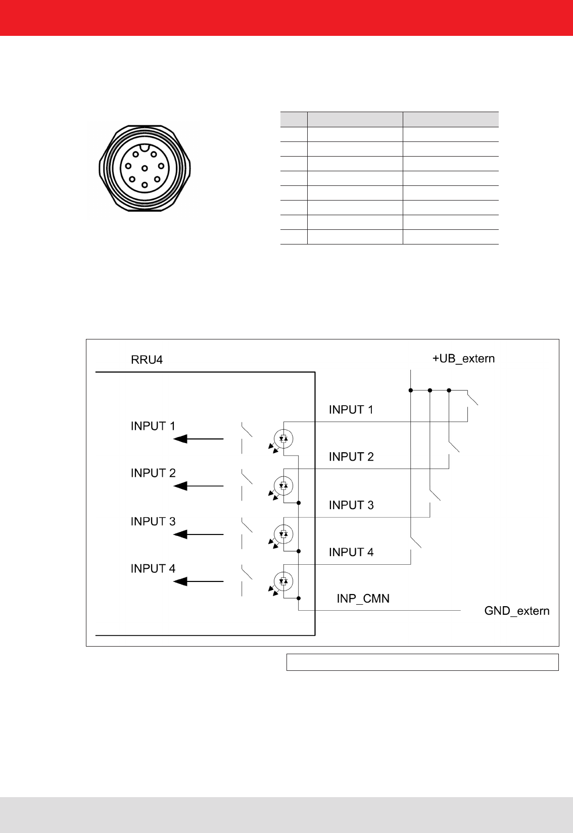
4.7. Digital inputs and outputs
The digital inputs and outputs are communicated via two eight-pin sockets in A-coding with M12 connection
threads. The inputs are double isolated from the power supply of the reader and can be operated irrespective of
the polarity of the input signal. For this reason there is a common pin for the inputs (INP_CMN). The connection
variants for the inputs are shown below. Depending on the application, the power to the inputs can be double insulated
from the external power supply to the reader, or not double insulated from it.
Figure: Inputs double insulated
The activation and evaluation can be performed using the software ReaderStart v2, with the DLL supplied, or by
access to the reader protocol.
Pin GPIO 1 GPIO 2
1 OUT_CMN OUT_CMN
2 INPUT 4 INPUT 1
3 INP_CMN INP_CMN
4 GND GND
5UB UB
6 OUTPUT 4 OUTPUT 2
7 OUTPUT 3 OUTPUT 1
8 INPUT 3 INPUT 2
1 2
7 3
6 4
5
8 central pin
18
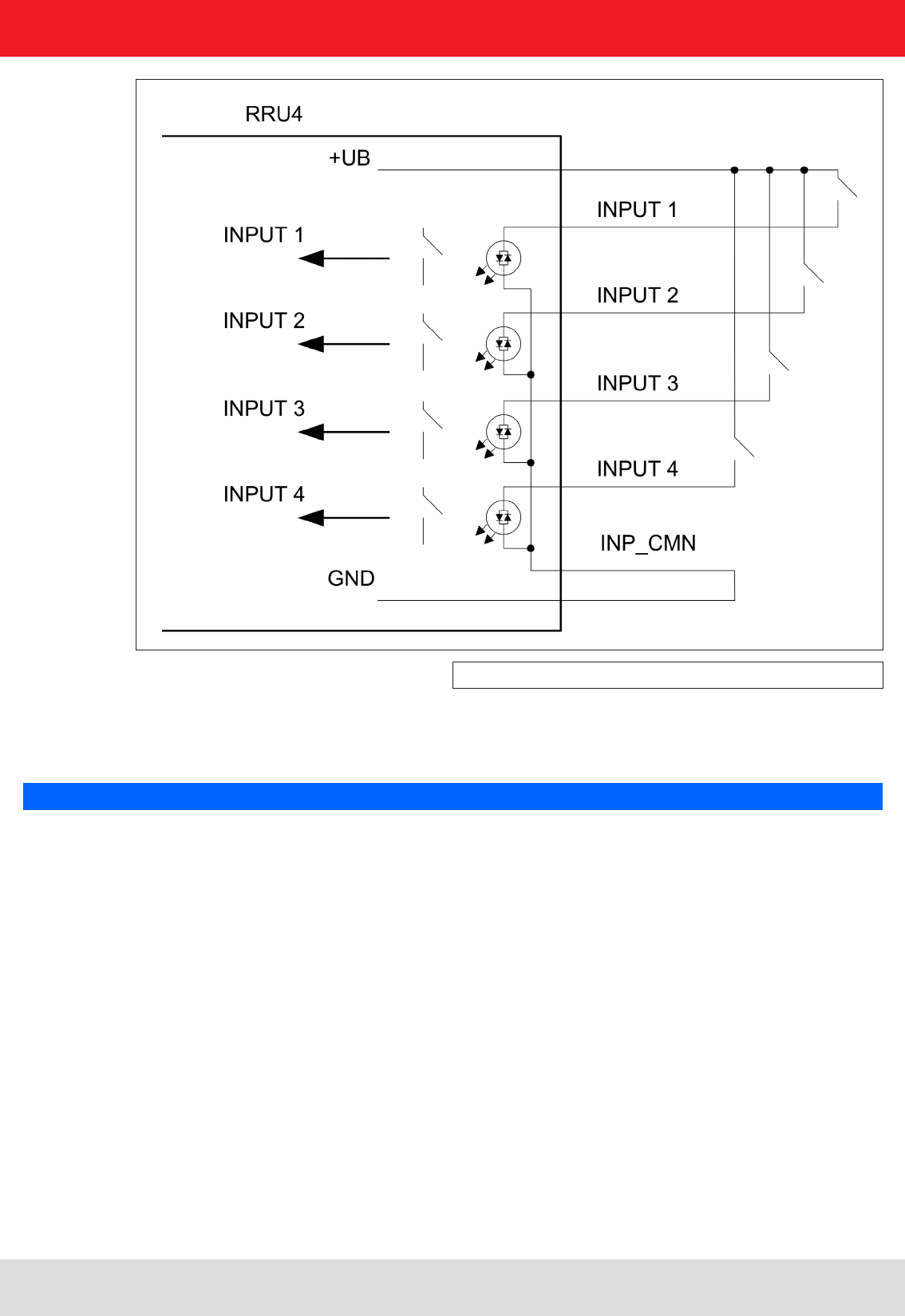
4. Connections and displays
Figure: Inputs not double insulated
The outputs are also double insulated from the power supply to the reader and have a common pin (OUT_CMN).
If the double insulation is not required, the power supply can also be taken directly from the reader.
Please note that the load per channel is limited to a maximum of 0.5 A, and the total load across all the channels must
not exceed 1.5 A. If the reader’s auxiliary power GPIO connection is used, the maximum load is 1.1 A. The inputs and
outputs are designed for a maximum voltage of 30 V DC. Further information can be found in the data sheet for the
reader. For operating the outputs with an external power source, only LPS (Limited Power Source) or NEC class 2
classifi ed power supply units are approved.
Note
19
4. Connections and displays
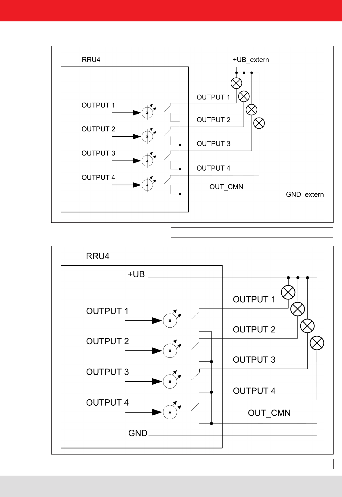
The connection examples for the outputs are shown in the next illustrations.
Figure: Outputs double insulated
Figure: Outputs not double insulated

20
4. Connections and displays
4.8. Antenna Connection
For the connection to the RFID antennas, the reader has four antenna connections that are of reverse
TNC design. Please only use the cable from the accessories or equivalent cable for this connection.
Note
Please only use cable suitable for the impedance (50 Ohm), as otherwise the performance of the reader will be
severely limited by the mismatch. If the mismatch is large, the reader may indicate a fault.
4.9. LED
The reader has a 2-colour LED for the indication of the operating state. The table below shows the colours used
and the related operating state.
Red Green Operating state
Xfl ashes approx. every 8 seconds Error during initialisation
X X Unit is booting
Flashes approx. every 8 seconds X Normal operation with heartbeat
Table: Indication of the operating states by the LED
4.10. Buzzer
Furthermore the reader is also fi tted with a buzzer which, in addition to the LED, indicates successful booting
(1 x short) or an error (2 x long).
For test purposes the reader can be operated using the demo software supplied. This software provides all the
necessary functionality of the reader for a test in a real environment. As an aid to confi guration, various basic
settings for application scenarios are provided.
As well as this documentation, the following documents and programs can be found on the CD supplied:
- data sheet for the reader
- specifi cation of the protocol for communication by the reader with a receiver
- catalogue of the RFID products currently available
- API DLLs for the simplifi ed activation of the reader with Borland and Visual Studio together with some simple
programming examples
- set-up program for the Kathrein reader start demo
- .Net Framework 4
- C++ 2008 redistributable
21
5. Software
5.1. System requirements
To ensure correct operation using the software on your PC/laptop, your PC/laptop should meet the following
minimum requirements:
Processor: X86 compatible
Memory: 512 MB RAM
Operating system: Windows XP (SP3), Vista (SP1), Windows 7 or higher
free hard disk memory for:
32-bit operating system 850 MB (including Microsoft .Net Framework 4)
64-bit operating system 2 GB (including Microsoft .Net Framework 4)
5.2. Installation
The demo software is installed by running KathreinRFIDDemoSetup.exe from the CD-ROM supplied. During
the installation a check is made whether the necessary preconditions for the installation are satisfi ed. This
means that a check is made whether all the dependencies such as the necessary Windows Service Packs, the
.NET Framework in the respective version together with the C++ redistributables are installed. If this is the case,
during this process the demo software and the DLL for controlling the reader are installed.
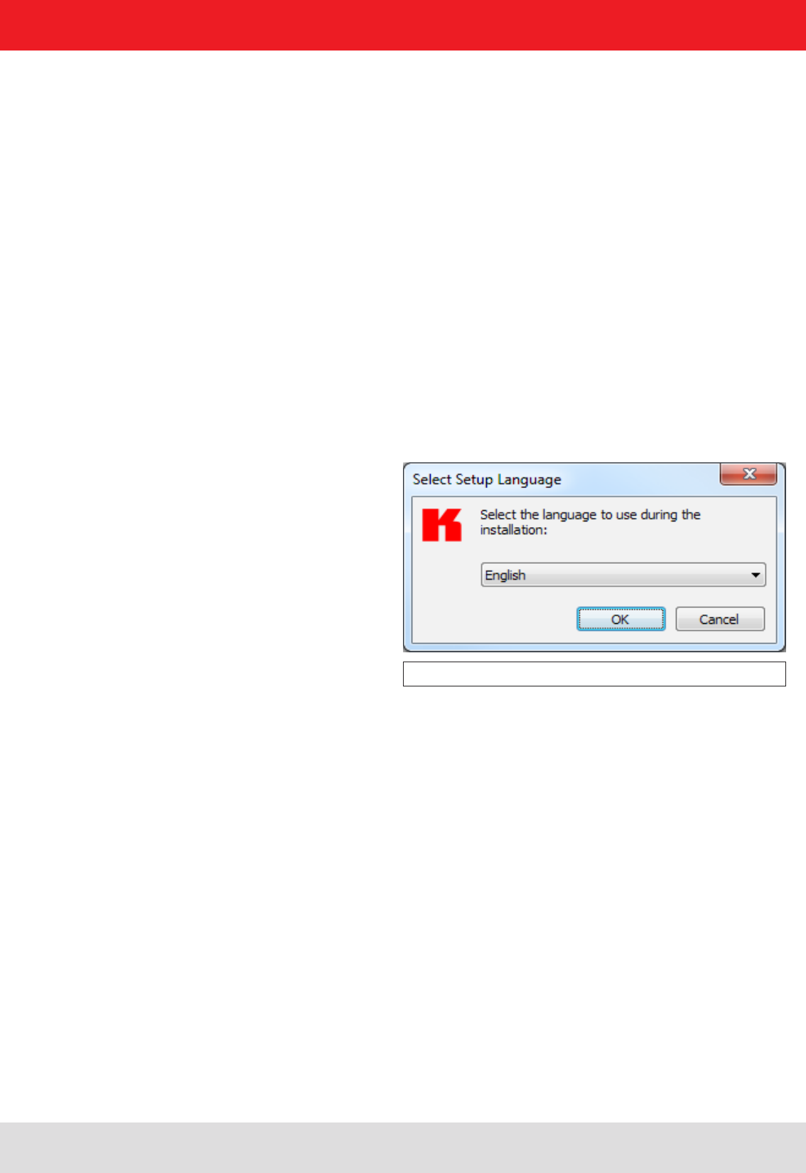
After the start of the set-up, you can change the language used during the installation in the window that now opens.
Confi rm your selection by clicking on the OK button.
Figure: Language selection for the installation
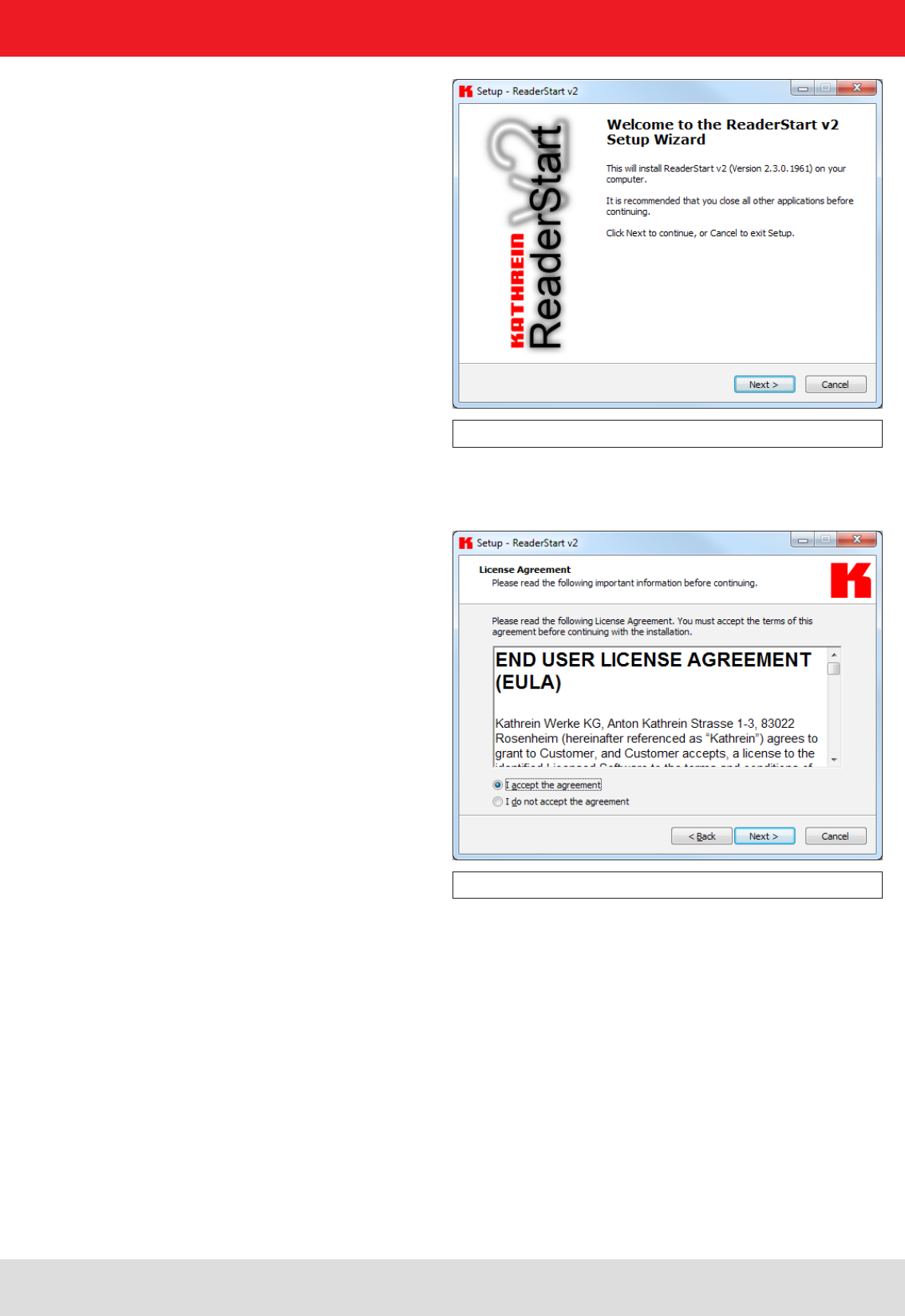
The welcome screen that now appears gives further information on the exact version issue of the reader start
software. This information can later be called up from the drop-down Info menu in the menu bar.
22
Figure: Welcome screen with software version
Clicking on the Next button takes you to the license agreement. Please read this through carefully; if you do
not accept the terms of the agreement you must decline to accept it. The installation is then terminated at this point.
Figure: Confi rmation of the license agreement
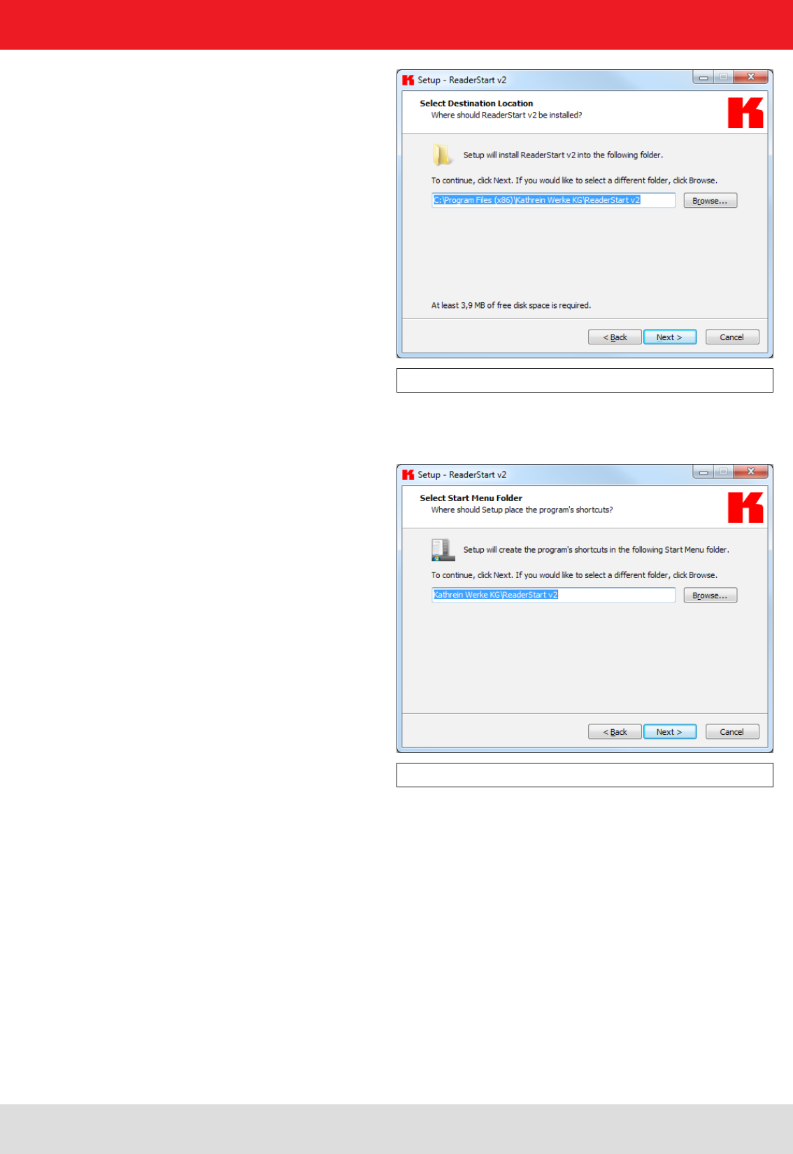
If you have accepted the license agreement, press the Next button, following which you can select the target folder in
which to install the software. Don't forget to select the target drive also.
5. Software
23
Figure: Selection of the installation folder
In the next screen you can customise the folder in the Windows start menu. Here, as in the previous windows,
you are offered the standard settings.
Figure: Selection of the folder in the start menu
5. Software
24
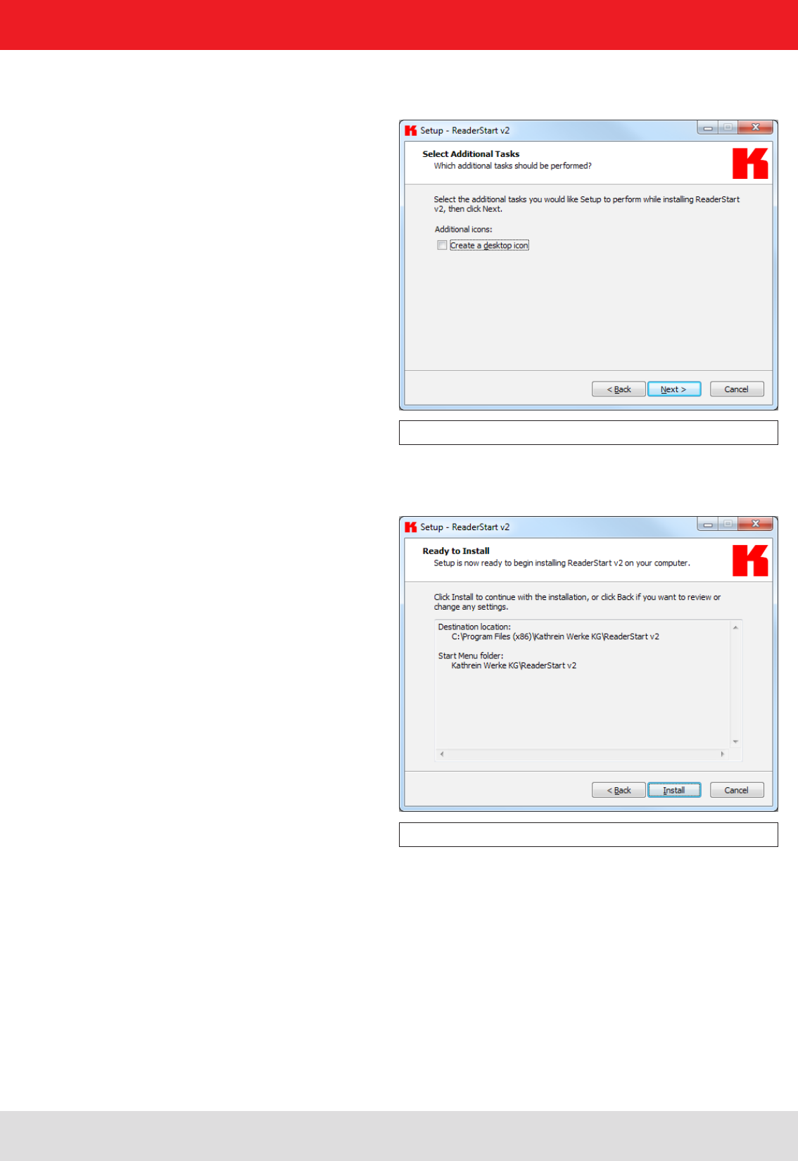
Figure: Selecting installation tasks
Finally a summary of all the installation tasks is shown. Click on the Install button to start the
installation. If during the installation procedure a request is made to restart the computer, please do so.
Figure: Summary of the installation tasks
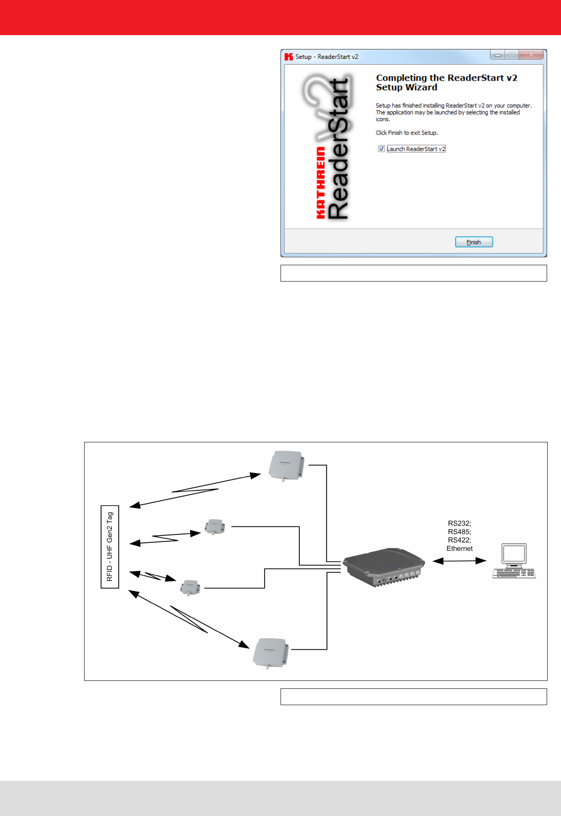
Successful completion of the installation is shown in the following window. If you do not wish to start using the
software straight away, please uncheck the Launch ReaderStart v2, box, otherwise the program will start immediately
once you click on Finish.
5. Software
In the following window you can specify whether you wish an icon to be included in the Windows Quick Launch
and/or on the Desktop. The default is to generate no icons.
25
Figure: Completing the installation
5. Software
5.3. Operation
In the following section, the ReaderStart v2 demo software for the KATHREIN RFID reader RRU4 is described.
Before the description addresses the user interface and the individual confi guration features and controls, the
principle of operation of this RFID reader system is described.
5.3.1. General information
An RFID system consists of the control computer, the reader itself, the antennas, antenna connection cables and
the tags. The fi gure below shows the schematic layout of the system:
Figure: RFID system
The tags consist of an antenna and a small chip. They are the real carriers of the information, the EPC. These
numbers identify the products or product groups. Alternatively the EPC can also be overwritten with your own
information.
To read information from an EPC tag, the reader emits an RF carrier via the active antenna and in this way supplies
all the tags is this RF fi eld with power. If now it is desired to read the information from a tag, this tag must be selected
26
5. Software
from the population of tags (singularisation). After successful completion of the singularisation, a handle is requested
from the tag. The rest of the communication with the tag is undertaken using this handle and the EPC is read.
The description of the tag is performed in the same way.
The tag's EPC is transmitted by the reader to the PC and can be displayed there with additional information. This
information includes, along with the time the tag was read, also the antenna used for communication with the
tag. It is always possible to communicate directly with the tag using this EPC, as soon as the tag is within range
of the reader.
The communication between ReaderStart v2 and the reader is performed via the DLL supplied. It provides
information on the user interface about all the unit's functions that are relevant to the user. Every connection between
the application and the reader over the various interfaces in the reader is made using this DLL. The functions that
can be used are listed in the header fi le “ReaderDll.h”.
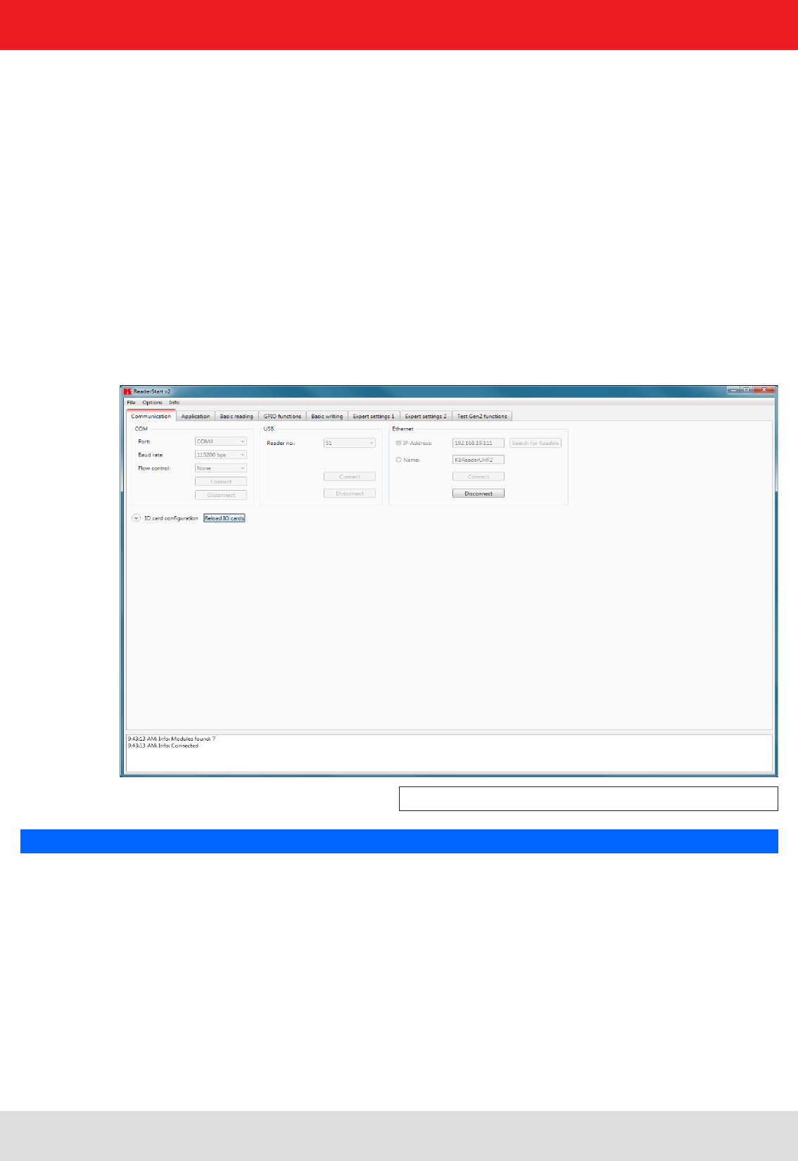
5.3.2. User interface for ReaderStart v2
The program is started by ReaderStart v2.exe. The splash screen is displayed until all the necessary DLLs have
been loaded in the background. After this the user interface shown below appears. This consists essentially
of the menu bar, the tabs together with the status fi eld.
Figure: ReaderStart v2 user interface
Note
Functions that are unavailable are greyed out in the program.
The settings and controls for the reader are divided into individual functional groups under different tabs.
The individual sheets can be selected using the tabs. The sequence of the tabs can be changed as required by
“drag and drop”.
All status messages from the reader and the program are shown in the status fi eld, and if desired logged. 3 message
types are defi ned:
• Info – shows which action was just performed
• Warning – indicates possible problems in the structure and confi guration
• Error – indicates that the desired action could not be executed
Every message is provided with a time stamp which is placed in the status fi eld which always lies above the
information itself.
27
5. Software
5.3.3. Menu bar
The menu bar allows the program to be customised to your own requirements. These include for example:
language settings, layout, status messages and calling up the program information. It consists of the items: fi le,
options and info.
5.3.3.1. File
There are a wide variety of parameters available for confi guring the RF front end. A complete setting can be saved
as a parameter set in the menu item fi le as an XML fi le, and later reloaded.
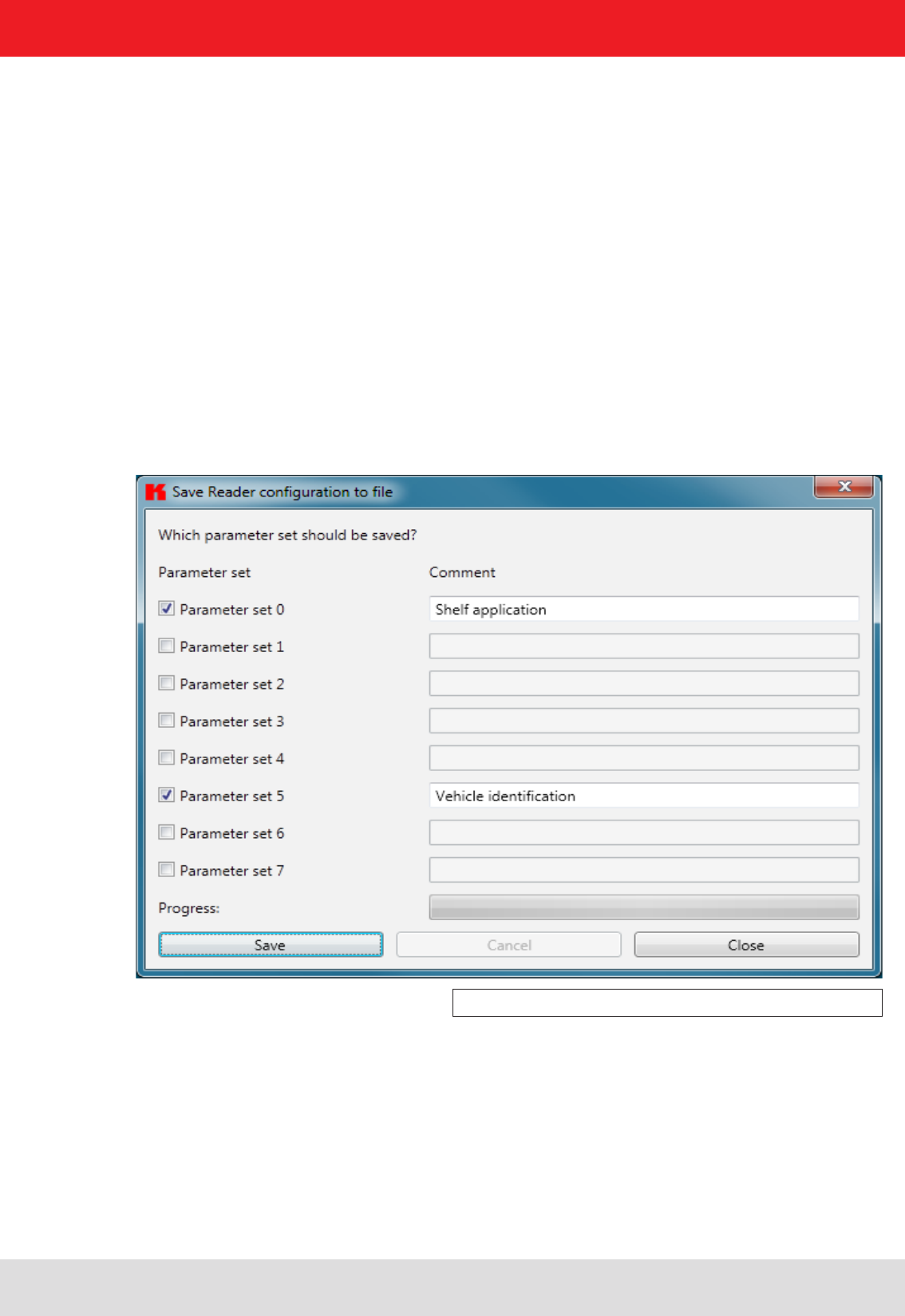
Under the item Save Reader Confi guration to File, a dialogue opens which displays all the available parameter sets
(0 - 7). The selection can be changed by setting the check. Furthermore each parameter set can be described briefl y.
Selecting Save opens a further dialogue in which a respective save location and a fi le name must be selected or input,
in order to successfully save the fi le. The progress of the save operation is shown by a progress bar.
Figure: Saving the confi guration in a fi le
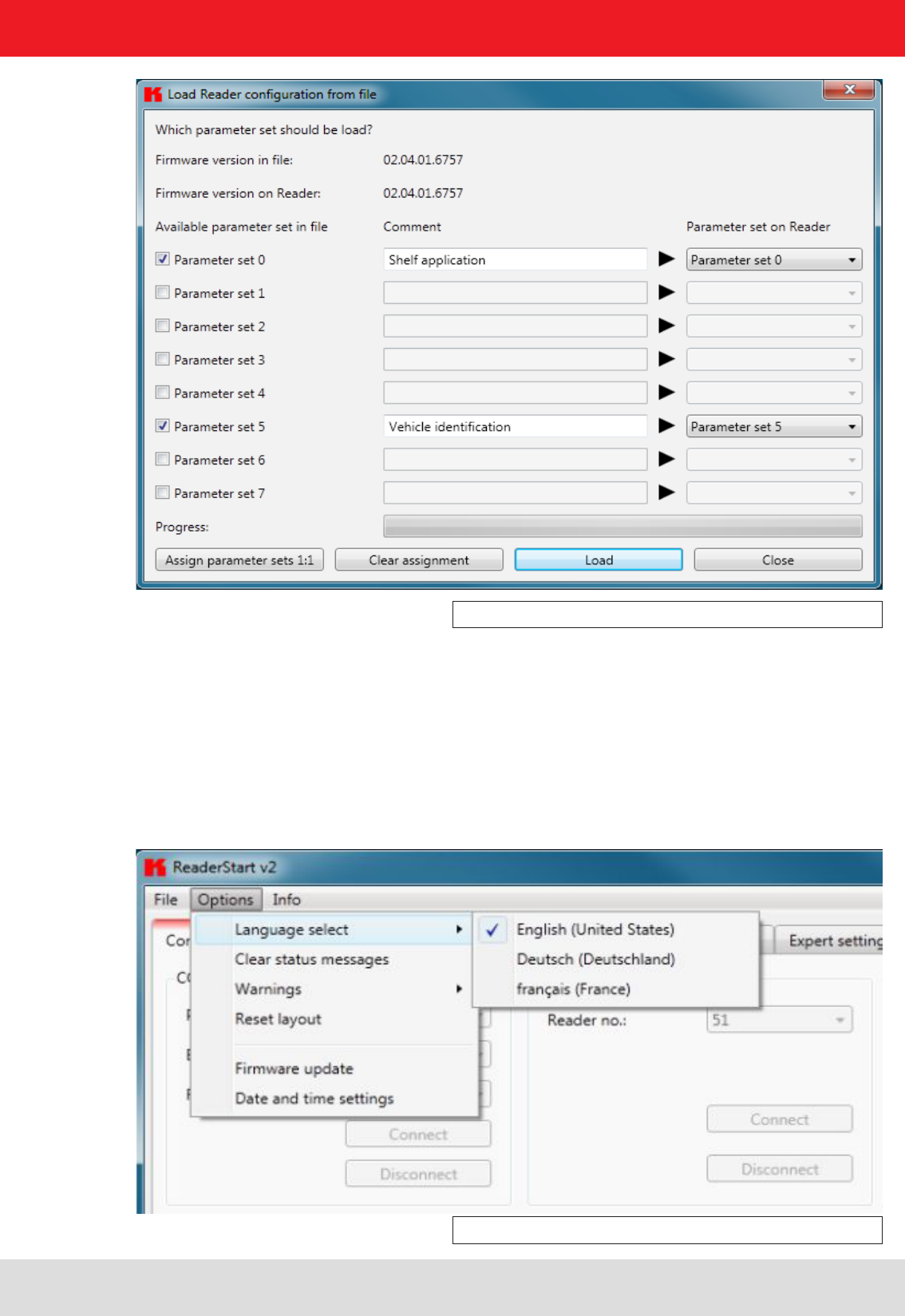
Reloading the settings starts with the selection of the parameter fi le. In the dialogue which opens, all available parameter
sets are displayed. The assignment of them to the individual save locations can be reassigned here. For this purpose
the desired parameter set on the reader can be selected in the drop-down menu. Selection of the item None means
this parameter set is not loaded into the reader. In the default setting a 1:1 assignment applies. Pressing the Assign
parameter sets 1:1 button resets all the changes in the assignment to the default. Pressing the Delete assignment
button deletes all assignments of the saved parameter sets to those in the reader. In the drop-down menu this is
indicated by None.
The status fi eld has a context menu which allows deactivation of warnings, information and errors in the status fi eld. Messages that
have expired can be deleted in this menu.
28
5. Software
Figure: Loading a confi guration from the fi le
5.3.3.2. Options
The Options are divided into two groups. One part offers the facility to change or reset some properties
of the program. The second part permits the reader to be provided with new fi rmware and to change its system time.
The fi rst group includes changing the language, selection of the warnings that are displayed, resetting the layout
and deletion of the status messages in the status fi eld. The language used in the program set to the desired
language by clicking on Language Selection in the menu item. The currently selected language is shown
by a check; if a computer restart is necessary in order to load the change, the program will indicate this.
Figure: Changing the language
29
5. Software
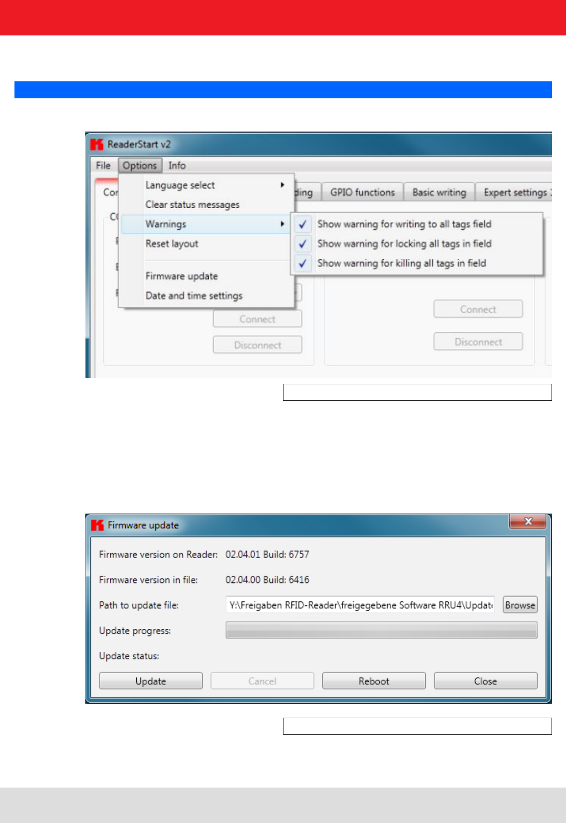
Under the item Warnungen (Warnings), the confi rmation queries for the actions Describe, Block or Deactivate the
tags in the fi eld are activated or deactivated.
Note
Changing the memory content of the tags can render them unusable.
Figure: Setting the warnings
If it is desired to recreate the original layout of the program in respect of window size and sequence
of tabs, this can be achieved by means of the Reset layout menu item.
The Firmware Update item permits the update of the reader fi rmware. The window that opens shows the version
currently mounted in the reader. After selection of a fi rmware fi le, this version is shown in the next line. Pressing the
Update button starts the procedure. The progress is shown in the Update progress line in a bar. After a successful
update the reader must be restarted, either by pressing the Restart button or by switching the power supply off and on
again.
Figure: Updating the fi rmware
30
5. Software
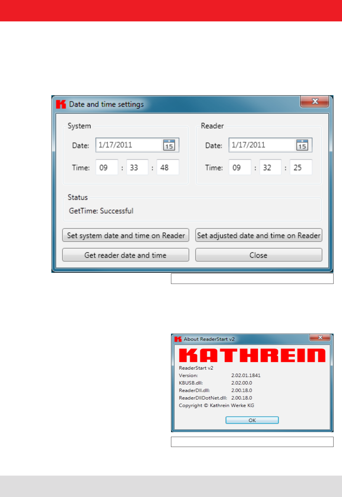
Figure: Setting the date and time
The reader has an integral clock, which can deliver the time stamp for a tag operation. This clock is set using the Date and
time settings in the menu. When this menu item is opened, it automatically reads the current date and time from the reader
and compares this with the date and time from the host computer. The date and time of the host computer can now be
loaded to the reader by pressing the Set system date and time on Reader button. There is also the facility to set the reader
date and time manually and load it to the reader. This is done by entering the desired date and time on the reader side and
pressing the Set adjusted system date and time on Reader button. The status line indicates which action was just executed
and whether the action was successful.
5.3.3.3. Info
This item on the menu bar allows information about the reader start software and the reader to be interrogated.
The version issue of the PC software can be interrogated under the fi rst item.
Figure: About reader start v2
31
5. Software
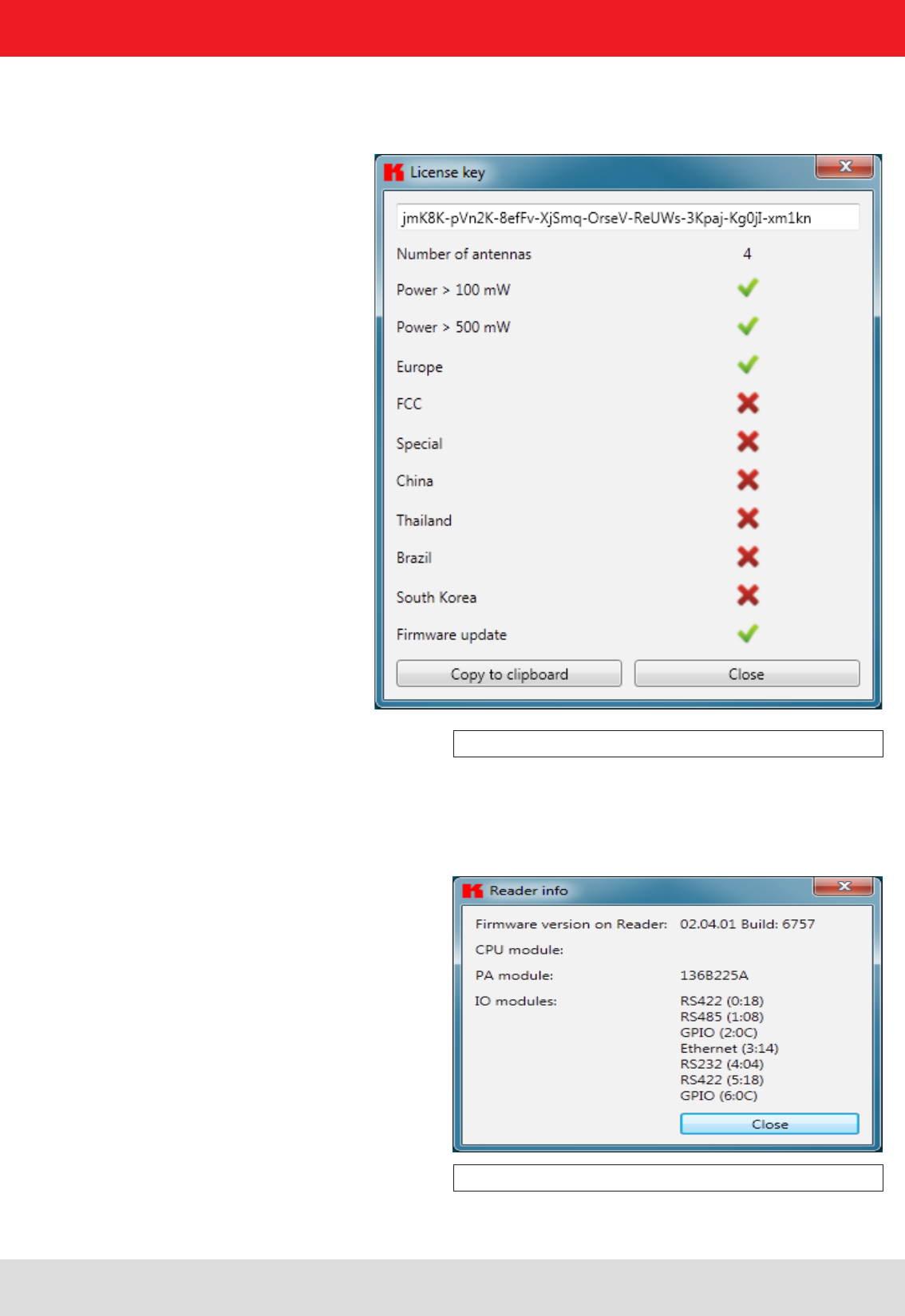
The second item automatically reads the license key. The key plays back various factory-set parameters of the reader.
In certain cases it may be necessary to send this key to Kathrein (rfi d@kathrein.de). The window that opens allows the
key to be copied to the clipboard.
Figure: Displaying the license key
The third item supplies detailed information about the software and hardware versions of the reader. The fi rmware is
specifi ed with version number and build number. The hardware issue is divided into CPU module, PA module and the
various I/O modules. The information about the I/O modules are stated in the format Insert position : module type .
Figure: Interrogating information about the reader
The Error status item reads the error status of the reader and shows all errors that are still outstanding in the status
fi eld.
32
6. Operating the reader
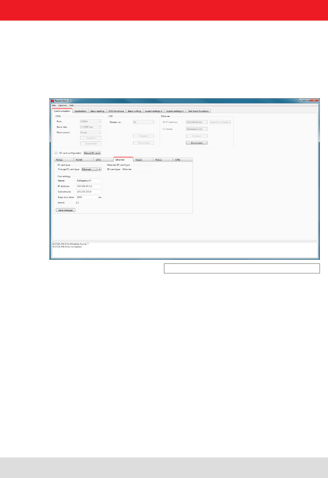
6.1. Communication
The communication tab groups together all the functions for establishing connections and confi guring the
interface cards. The various communication connections are grouped under 3 headers, COM for serial
connections via the COM port (RS232/485/422), USB for connections up to version USB 2.0 and Ethernet for
connections via TCP/IP.
When the connection is established, the program interrogates the information about the installed I/O cards. The
information can be viewed and changed via the I/O card confi guration.
6.1.1. COM header
The serial interface is used for communication with the reader via RS-232, RS-485 and RS-422. The RS-485/ RS-422
interface card supports the standard data rates of the serial interface on a PC. A level converter is also required for
communication to convert the RS-232-compliant signal from the PC into a differential RS-485/RS-422 signal.
A serial COM port on the PC can be opened in this group box. For this purpose the correct serial interface must
be selected in the Port drop-down list box. Only the ports available on the PC are displayed in this list box.
It is not checked whether this port is already in use by other applications.
In the menu below the desired Baud rate must still be set, and if used, the fl ow control setting. The COM port is
opened by clicking on the Connect button, which blocks it for other applications. If this port is already being
used by another application, a corresponding error message is output. If the port is free, the reader can be
operated using this port.
Pressing the Disconnect button breaks the connection and releases the interface again.
Figure: Tab for the Communication by Ethernet I/O card
6.1.2. USB header
If a RRU4 is connected to the PC via USB, the unit is installed in the system as a USB HID-compliant device.
Correct logging in can be seen in the program if a reader number appears in the drop-down menu. This number is
unique for each reader. If several readers are connected to the PC, the related reader can be selected on this menu.
Clicking on Open now establishes the connection between the reader and PC.

33
6. Operating the reader
6.1.3. Ethernet header
The Ethernet connection can be achieved by linking the reader into an existing network, or by a direct connection
between the reader and a control computer. For direct connection of the reader to the PC, a cross-link cable
is required, unless the LAN interface on the PC supports “auto-mdi-x”. Alternatively two standard patch cables
and a switch can be used.
Note
From reader fi rmware 2.04, the reader in the ex-works condition has the IP address 192.168.0.1 with the network
mask 255.255.255.0. Reader versions earlier than this are confi gured for DHCP.
Note
The IP addresses of the control computer and the reader must be in the same IP range, but they must not be the same.
The network mask on the other hand must be identical.
6.1.4. I/O card confi guration
The communication interface settings can be changed using the IO card confi guration. All available I/O cards are
displayed here in the form of tabs. Clicking on the respective tab opens the associated card and displays all respective
confi guration parameters, together with the card type that was detected.
Under the IO card type header there is a drop-down menu, in which the card type can be set to Auto detect, Card not
used or to the actual card type. Automatic detection restores the interface to the default settings. What these settings
are is described in the following sections in relation to the interfaces. If the card type is set to not used, this interface
can no longer to used.
All card-specifi c confi guration parameters are displayed on the card sheet when the recognised card type is set.
These parameters are described in the following sections for the respective card. The settings are saved to the
reader by pressing the Save changes button.
Note
The new parameters, provided nothing to the contrary is specifi ed for the specifi c card, become valid only when the
reader has been restarted. If incorrect parameters are loaded, the reader can no longer be accessed!
To integrate the reader into a corporate network, please contact your administrator who will be able to allocate
you a spare IP address and assign the correct network mask. Alternatively the reader can also be confi gured to
obtain an IP address automatically. For this service, referred to as DHCP, an appropriate DHCP server must be
operating in the network. You can obtain more details about this from your network administrator.
In order to establish the connection to the reader, the program offers two options. On the one hand, it is possible
to communicate directly with the reader by entering the IP address, on the other hand it is also possible to
establish a connection using the reader's host name.
For the connection using a host name, there must be a correspondingly confi gured DHCP server and a DNS
in the network. After power up, the reader makes a DHCP request and logs on to the DHCP server. This assigns
the reader an IP address and reports the network name and IP address to the DNS server. If now the connection
has been established, the IP address of the reader is determined by an enquiry on the DNS server.
The establishment of the connection is achieved if the establishment of the connection is selected under the
Ethernet header, meaning the selection of the IP address or name. For this, the correct IP address or the host
name of the reader must be entered in the corresponding fi eld. Pressing the Connect button then opens the
data channel to the reader.
If you wish to establish a connection via an IP address, the IP address fi eld must be highlighted and
this address entered in it. The connection is established by clicking on the Connect button.
34
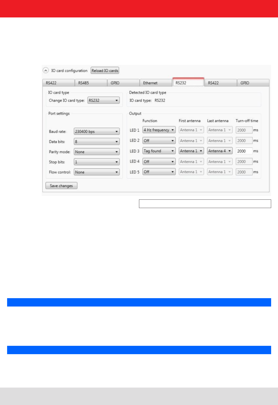
6.1.4.1. RS232
The serial interface supports communication to the EIA232 standard and, depending on the expansion stage, has fi ve
outputs for activation of LEDs. The confi guration parameters are split between the Port settings and Output headers.
6. Operating the reader
Figure: Confi guration of the RS232 card
The communication parameters are grouped as follows:
1 Baud rate – the speed of the connection. All popular serial data rates up to 230,400 bps are supported
2 Data bits – the number of data bits transmitted per byte. The card supports 5 – 8 data bits.
3 Parity – a bit for security of the data transmission
If None is selected, this bit is not transmitted. For all other settings this bit is transmitted. The even or odd parity
checks whether the number of bits including the parity bit is even or odd. Based on this information the recipient
can determine whether a bit has been switched. Mark and space specify whether the parity bit should be
transmitted with a fi xed 1 or 0. In this case no data transmission security is achieved.
3 Stop bits – specifi es whether the transmission of a byte should be terminated with one or two stop bits.
4 Flow control – for readers with the appropriate interface, this allows specifi cation of whether the synchronisation
between the PC and reader should be by software None or by hardware wires (Hardware).
Note
Note that for a point-to-point connection, the setting of this parameter must be the same for both participants,
otherwise no connection can be established. RS232 readers, whose serial interface is performed
via 4-pin M12 connector, do not support hardware fl ow control.
The RS232 card has a further fi ve outputs, which can be used for activation of LEDs. The confi guration parameters
for these outputs can be found under the Output header.
Note
Not all reader hardware issues support this functionality. Please check the reader data sheet for information.

35
6. Operating the reader
If the LEDs are present (only for ARU), the LED channels can be assigned various functionalities under this heading.
Further parameters can be activated, depending on the function selected. The following functions are available:
1 Off – the selected LED is deactivated
2 On – the selected LED is always on
3 1Hz frequency – the selected LED fl ashes at a frequency of 1 Hertz
4 2Hz frequency – the selected LED fl ashes at a frequency of 2 Hertz
5 4Hz frequency – the selected LED fl ashes at a frequency of 4 Hertz
6 8Hz frequency – the selected LED fl ashes at a frequency of 8 Hertz
7 RF on – the LED lights up for Turn-off time milliseconds as soon as the radio frequency is
present at the antenna First antenna to Last antenna.
8 Antenna error – the LED lights up for Turn-off time milliseconds as soon as an antenna error occurs at antenna
First antenna to Last antenna.
9 Tag found – the LED lights up for Turn-off time milliseconds as soon as a tag is found at the antenna First antenna
to Last antenna.
10 RF on – the LED lights up for Turn-off time milliseconds as soon as an operation on a tag was successful at the
antenna First antenna to Last antenna.
11 Protocol access – the LED can be switched on and off directly via the protocol.
Default confi guration:
Baud rate: 9600
Data bits: 8
Parity: None
Stop bits: 1
Flow control: None
LEDs: Off
6.1.4.2. GPIO
The GPIO card allows the reader to interact with its environment. In this tab, the inputs and outputs can be
confi gured for the respective application under the headings Input and Output.
Note
Refer to the electrical characteristics of the inputs and outputs in the data sheet; if these characteristics are
exceeded the card and the reader may be damaged.
Figure: Confi guration of the GPIO card

36
6. Operating the reader
Each input channel has two confi guration parameters available. The Invert logical input option negates the electrical
input signal and uses this status for processing in the reader. If the check is not set, the signal is used unchanged.
Depending on the sensor being used (mechanical or electrical switch), a debounce time in milliseconds can be assigned
to each channel.
The outputs from the card can be assigned various functions. Further parameters can be activated, depending on the
function selected. The following functions are available:
1 Off – the selected output is deactivated
2 On – the selected output is always on
3 1Hz frequency – the selected output fl ashes at a frequency of 1 Hertz
4 2Hz frequency – the selected output fl ashes at a frequency of 2 Hertz
5 4Hz frequency – the selected output fl ashes at a frequency of 4 Hertz
6 8Hz frequency – the selected output fl ashes at a frequency of 8 Hertz
7 RF on – the output is active for Turn-off time milliseconds as soon as the radio frequency is present at the antenna
First antenna to Last antenna.
8 Antenna error – the output is active for Turn-off time milliseconds as soon as an antenna error occurs at antenna
First antenna to Last antenna.
9 Tag found – the output is active for Turn-off time milliseconds as soon as a tag is found at the antenna
First antenna to Last antenna.
10 RF on – the output is active for Turn-off time milliseconds as soon as an operation on a tag was successful at the
antenna First antenna to Last antenna.
11 Protocol access – the output is released and can be activated with all KBRP commands for GPIO.
Note
If the output is not set to protocol access, it cannot be accessed when processing action lists. See the
GPIO functions section for more details on action lists.
Once all the settings have been performed, the changes are loaded to the reader by pressing the Save changes
button, and take effect immediately.
Default confi guration
No default confi guration is provided for this card.
Note
If this card setting is changed from Auto detect or Card not used to GPIO, the reader must be restarted so that the
card is correctly initialised.
37
6. Operating the reader
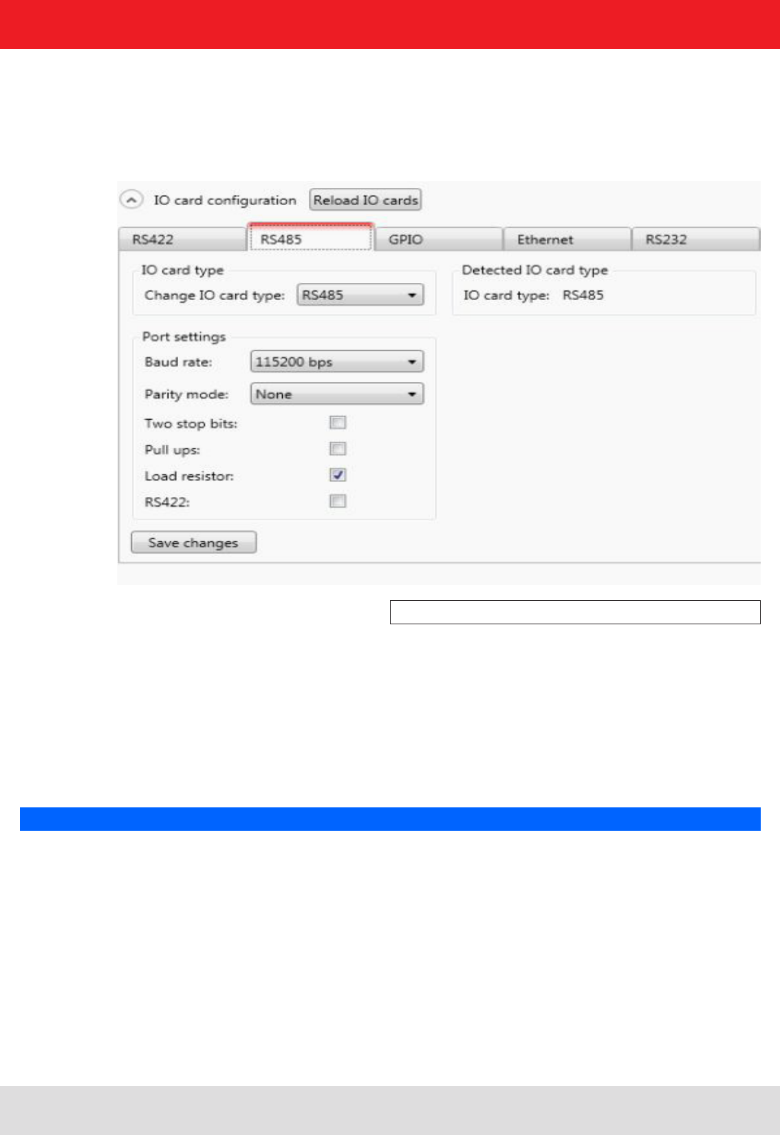
6.1.4.3. RS485
In order to establish a serial symmetrical connection to the EIA-485 standard, a RS485/RS422 card is required for
the reader. In addition to the parameters Baud rate, parity and stop bits, which are identical to RS232, the tab for
confi guration of this interface has certain other specifi c settings under the Port settings header.
Figure: Confi guration of the RS485 card
The parameters have the following meaning:
1 Pull-up – when this parameter is set, the differential wires are pulled up with 120 Ohm to a fi xed reference
potential (+5 V and GND). This procedure is recommended when the signal ratios between the communications
participants are critical.
2 Load resistor – terminates the differential wires against each other with 120 Ohm. This variant is required
when the reader forms the end point of the network.
3 RS422 – activates the RS422 mode of the interface card. This changes over the connection from 2-wire for
RS485 to 4-wire for RS422. This achieves a full duplex connection with differential RX and TX wires.
Note
Note that for a point-to-point connection or for connection of the participants in a network, the setting of this
parameter must be the same for both participants, otherwise no connection can be established.
Default confi guration:
Baud rate: 115200
Data bits: 8
Parity: None
Stop bits: 1
Load resistor: activated
RS422: deactivated
38
6. Operating the reader
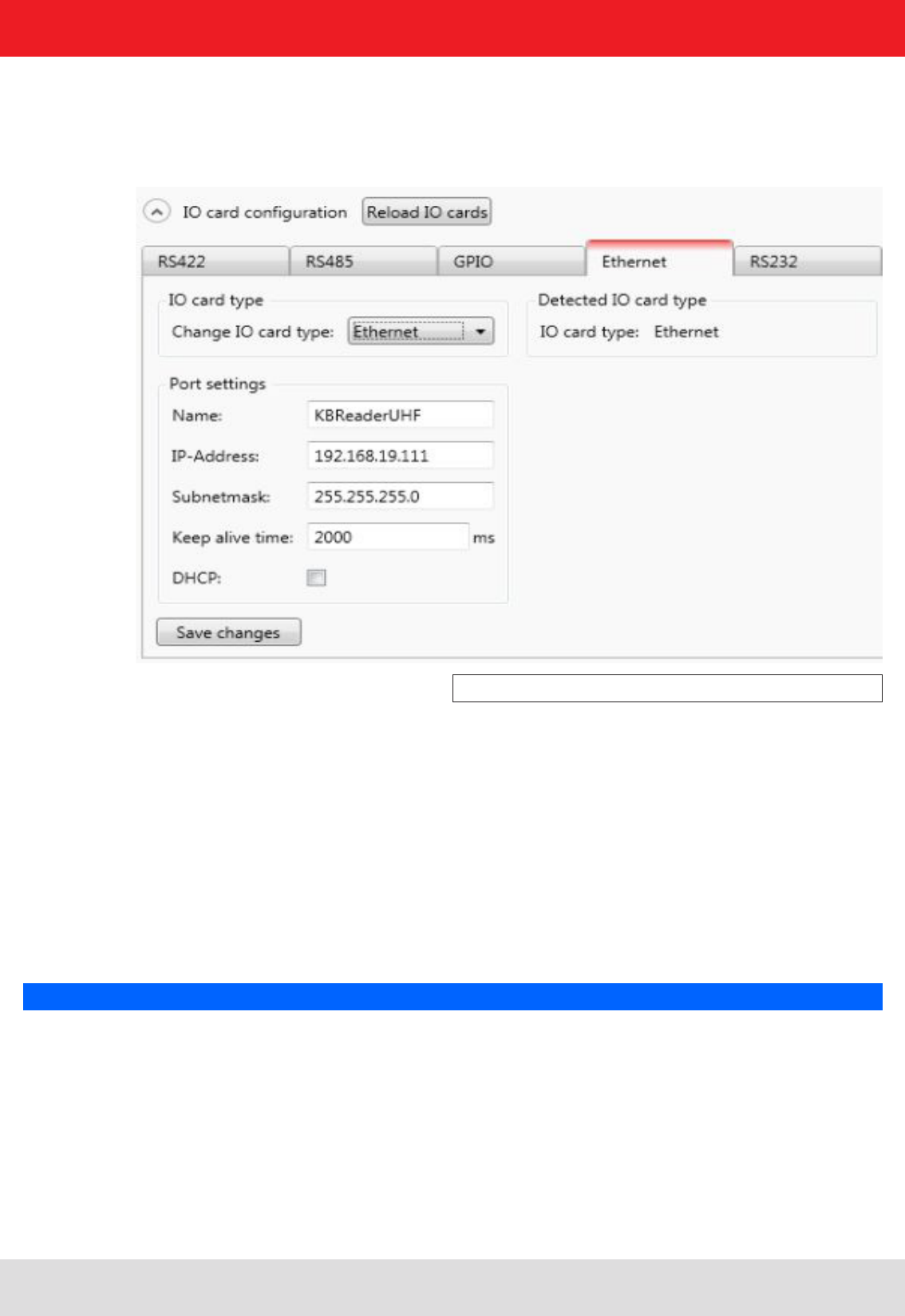
6.1.4.4. Ethernet
The parameters Name, IP-Address, Subnetmask, Keep-alive time and DHCP can be set for the Ethernet card on the
reader.
Figure: Confi guration parameters for the Ethernet module
The parameters have the following functions:
1 Name – Here the host name of the reader which is logged on to the DNS server is stated. The reader can be
addressed by this name as an alternative to the IP address.
2 DHCP – activates the automatic issuing of an IP address by a DHCP server; if the network has a confi gured
DNS server, the host name of the reader can also be used.
3 IP address – for manual issuing of the address. This parameter can be used only if the DHCP is deactivated
4 Subnet mask – for manual issuing of a network mask. This parameter can be used only if the DHCP is
deactivated.
5 Keep-alive time – this time specifi es the intervals of time at which the reader sends a data packet to check
whether the receiver is still available. If the connection to the reader is broken, the reader shuts down the
connection. If this parameter is deactivated (0 ms), the socket is shut down only when the reader is restarted.
Note
If no keep-alive time is set it may happen that the reader cannot take up any further connections because the
existing connections have not been properly shut down (e.g. following a breakage in the wire). In this case the
reader has to be restarted. It is recommended that the keep-alive time is used to check the connection between the
reader and PC.
The data are saved in the reader by pressing the Save changes button. The data are however not loaded to the working
confi guration until the reader is restarted.
39
6. Operating the reader
Note
If the interface is wrongly confi gured, no connection to the reader can be established. Please make a note of the
data settings.
Default confi guration:
Host name: KBReaderUHF
IP address: 192.168.0.1
Subnet mask: 255.255.255.0
Keep-alive time: 2000ms
DHCP: deactivated
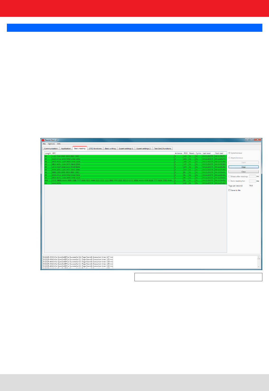
6.2. Basic read functions
This tab is split into two columns; the fi rst column contains a table with information about the tags that were read,
the second column contains the controls for controlling the read process.
Figure: Basic read functions tab
In addition to the Electronic Product Code (EPC), the table contains the following data:
1 Length – gives the length of the EPC in bits, valid lengths 0-496 bits
2 EPC – the EPC of the tag in hexadecimal format
3 Antenna – the antenna port by which the tag was read, valid values 1-4
4 RSSI – the dimensionless number for the signal strength of the tag answer, valid values 0-255
5 Readings – states how often this tag was successfully read
6 Cycles – states how often an inventory was started
7 Last read – the time stamp of the last time the tag was read
8 First read – the time stamp of the fi rst time the tag was read
For better visualisation, the appearance and disappearance of the tag is shown by colour in the fi eld. When a tag
comes into the fi eld, the line with the tag information is shown green; when it disappears again, the line is shown red.

40
6. Operating the reader
The controlling of the read process is performed in the second column of the tab. This allows differentiation between
two different modes.
6.2.1. Synchronous mode
This mode is intended for applications when the requirements for timing are not so demanding. This mode allows
the facility to switch the carrier off during the idle times, thus saving power.
The inventory of the tags (the read process) is performed across all the antennas that are confi gured. Once all
tags in the fi eld have been read on the last antenna, data are sent to the PC. The inventory of the tags is then
automatically retriggered by the PC.
The Pause after reading option specifi es how many milliseconds the pause between two inventories should be. During
this waiting time the carrier can be deactivated. See section 7 “Reader confi guration” for more information about
switching off the carrier.
In order to keep the time between inventories as short as possible in synchronous mode, data transmission between
the inventories can be dispensed with. That means that the reader saves all the tags that it fi nds in the fi eld in
its internal RAM. After a confi gurable time this results list is sent to the PC. This time is given in milliseconds by
the Bulk read parameter.
The current reading performance is displayed under the item Tags per second.
Note
The read rate is infl uenced by many parameters; these include in addition to the selected broadcasting profi le
with the respective data rates also application-specifi c data such as how many tags the reader should expect in
the fi eld. You can optimise these parameters using the expert settings 1 and 2. There is more about this in
the following sections. If you are unsure whether the settings you have chosen are optimum for your application,
please contact KATHREIN Support.
If the tags that have been read are to be saved to a fi le, this can be done by activating the Save to fi le option. The
EPC, the length of the EPC, the antenna on which the tag was read, the RSSI valuetogether with the time stamp when
the tag was read are saved.
The data are then saved in a csv fi le in the Program directory. The fi le can opened or deleted in the context menu
for this item.
6.2.2. Asynchronous mode
This mode is intended for applications for which maximum performance is required.
The reader starts the inventory as quickly as possible, and at the end of an inventory it does not deliver every tag
that was read to the PC, but only those that had newly appeared in the fi eld or newly left it. This allows the time
required for communication with the higher level to be minimised.
The timing of when a tag was reliably read in the fi eld and when the tag no longer appears in the fi eld can be
defi ned more precisely using parameters. Details of these ObservedThresholdCnt and ObservedTimeoutCnt
parameters can be found in section 7 “Reader confi guration”.
Note
The read rate is infl uenced by many parameters; these include in addition to the selected broadcasting profi le
with the respective data rates also application-specifi c data such as how many tags the reader should expect in
the fi eld. You can optimise these parameters using the expert settings 1 and 2. There is more about this in
the following sections. If you are unsure whether the settings you have chosen are optimum for your application,
please contact KATHREIN Support.
If the tags that have been read are to be saved to a fi le, this can be done by activating the Save to fi le
option. The data are then saved in a csv fi le in the Program directory. The fi le can opened or deleted
in the context menu for this item.
Once the mode and the parameters have been selected, the read process can be started. Both modes are stopped
by pressing the Stop button. The Delete button removes all tag entries from the table.
41
6. Operating the reader
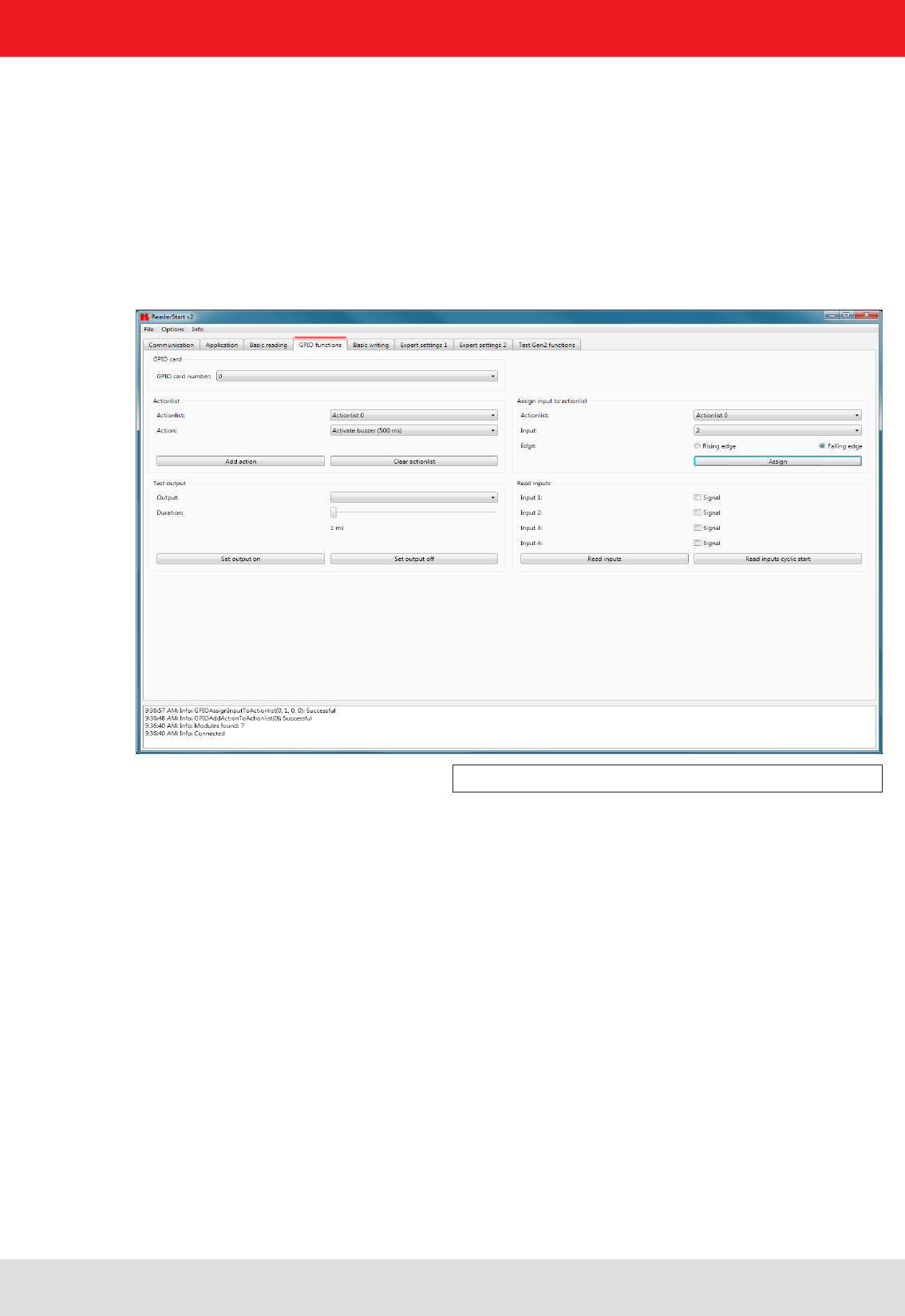
6.3. GPIO functions
Readers with GPIO functionality offer the facility to set up small controls which trigger the reader for instance by a
light barrier or which trigger an action at the outputs of the reader by reading specifi c tags. Such an action might be
switching an output to control the fl ow of goods.
The GPIO function tab allows the user of the program the facility to load or switch inputs and outputs manually. For
more complex procedures, action lists can be created here, which execute a sequence of commands on the reader.
This list can then be linked to various inputs.
This confi guration sheet is divided into 5 different headers. In order to perform settings on a card, fi rstly the card
number must be selected in the GPIO card drop-down menu. This shows only cards of this type.
Figure: GPIO functions tab
The Test output header can be used in order to selectively connect an output manually. In order to enable
this access, the respective output of this card must previously have been connected to protocol access (see
I/O card confi guration). The output in the drop-down menu is now selected in the header, and time is defi ned
using the Duration parameter, until the output automatically returns to its idle mode. The connections can
now be made using the Set output on and Set output off buttons.
The inputs to the reader can be interrogated under the Read inputs header. Whether an input is set or
not is shown in the signal fi elds. A one-off read process can be triggered by pressing the Read inputs
button. If this interrogation should be performed automatically, this process can be started by pressing
the Read inputs cyclic start button.
To automate the processes, command sequences in the form of action lists can be stored on the reader. These are
triggered by a change of fl ank at the selected input on the respective GPIO card.
The action lists consist of a sequence of individual actions, which can be loaded in the form of an ML fi le in
the context menu of the Action item under the Action list. This fi le can be created or edited manually, using
a text editor. The syntax can be seen from the example. The individual actions can be selected from the
functions described in section 7 “Reader confi guration”.
The fi le is saved in the folder “..\My fi les\Kathrein Werke KG\ReaderStart v2\” and can be edited using a text editor.
In order to use the newly added actions in the program, the fi le must be reloaded into the context menu.
The action list must be selected from the drop-down list. The desired actions are now selected individually
from the action list and added to the action list in the sequence in which they are to be executed. Pressing the
Clear action list button clears down the selected list.
42
When the action list has been created, it is assigned under the Assign input to action list header to an input and a
selected fl ank. If it is desired to assign the list to both fl anks, the assignment must be made once for the positive fl ank
and once for the negative fl ank.
The assignment can be cancelled again by a restart/reset of the reader or by assignment of the No action list
item.
Note
The action lists that are created are stored only in the RAM of the reader. On restarting the reader these lists are
deleted again.
6. Operating the reader
6.4. Expert settings
The ReaderStart v2 software is a powerful tool for confi guration of the reader. It allows the reader to be customised
to any application. The expert settings 1 and 2 allow the reader's RF interface and communications profi le to
be optimised to the tag so that the reader is optimally customised to the application.
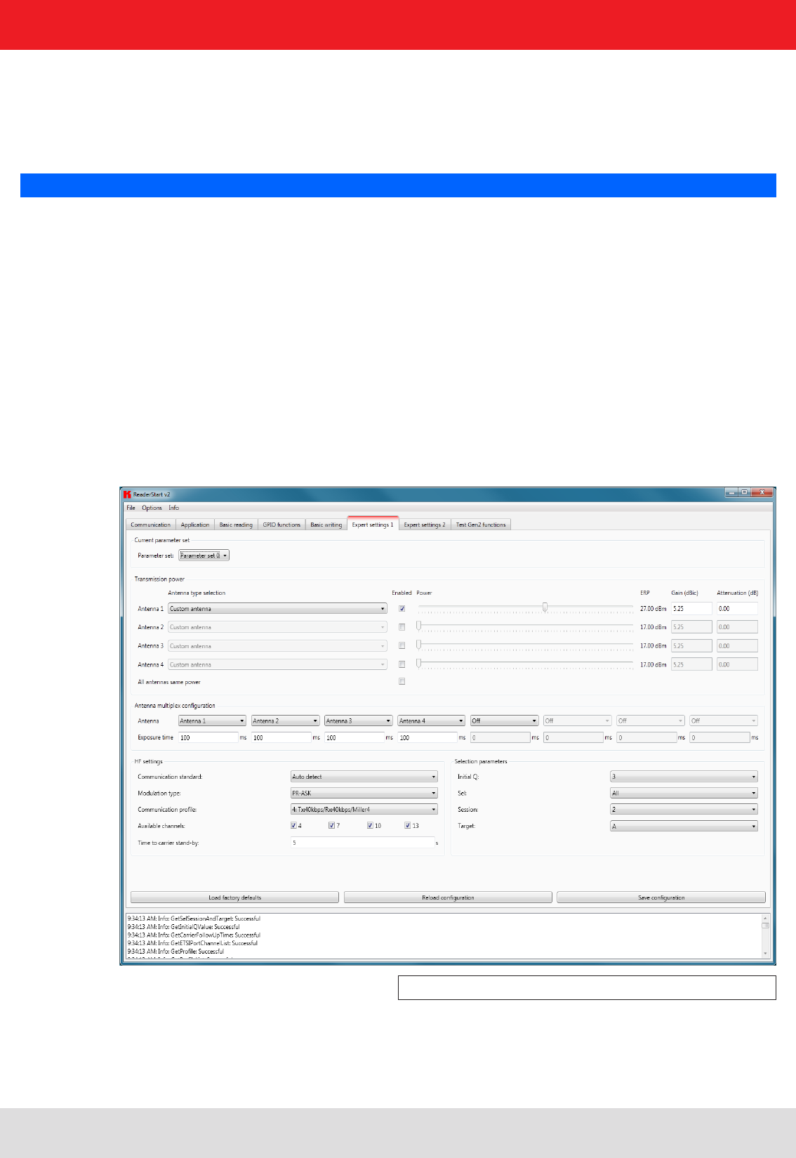
6.4.1. Expert settings 1
There are eight parameter sets available for saving the confi guration of the reader. All settings for the transmission
power, the antenna multiplex confi guration, the RF settings and the air interface parameters can be saved in these
memory slots. Other parameters can be changed in Expert settings 2. See section 7 “Reader confi guration” for more
information about the individual parameters.
Figure: Expert settings 1 tab

43
6. Operating the reader
Pre-setting can be selected under the Current parameter set header. This is done by selecting a parameter set in
the drop-down menu. This parameter is now active and loaded, and the headers are updated. When all the desired
changes have been made, they can be saved. The changes to the settings can be discarded by pressing the Reload
confi guration button. The parameter set can be reloaded by pressing the Load factory defaults.
Under the Transmission power header, the parameters of the transmission path can be entered; these include the
transmission power, transmission channel (only EU) and spectrum. The applicable standards in the related approval
region are to be observed when setting the transmission power.
Note
To operate the reader in accordance with the related national standards, the antenna gain and the cable
attenuation must be taken into account in the transmission power setting. In no circumstances is it allowed to
exceed the permitted transmission power. Failure to observe this instruction can result in non-compliant operation
of the reader rendering void the unit's type approval.
6.4.1.1. Transmission power
The radiated power is limited in Europe in accordance with ETSI 302208 to 2 W ERP. In the FCC region, max. 1 W
connected RF power applies with an antenna gain of 6 dBi. If the antenna gain is greater than 6 dBi, the RF power must
be reduced accordingly. While the European standard refers to a half-wave dipole, FCC part 15 refers to an isotropic
radiator.
To set the transmission power, the length-dependent cable attenuation and the antenna gain must be included in
the calculation of the transmission power. An example for the calculation of the transmission power for Europe and
FCC is given in the following.
The following applies to the European approval region:
The cable attenuation is the length-dependent attenuation of the cable at the related frequency:
The antenna gain is stated in various different units. These units include dBi and dBic. The units dBi and dBic refer
to an isotropic (spherical) radiator, where dBic refers to a circularly polarised isotropic radiator and dBi to a linearly
polarised isotropic radiator.
In the European approval area, the radiated power must not exceed 2 W ERP. This fi gure refers to a half-wave dipole.
The relationship shown below exists between an isotropic radiator (dBi) and a half-wave dipole.
PReader = PERP + DKabel – GHW
PReader...Transmission power of the reader in dBm
PERP
......Transmission power based on a half-wave dipole in dBm
DKabel.....Cable attenuation in dB
GHW......Antenna gain based on a half-wave dipole
DKabel = l*DdB/m
DKabel....Cable attenuation in dB
l...........Length in m
DdB/m.....Attenuation in db/m at frequency

44
6. Operating the reader
If the gain of the antenna is referred to the polarisation of a circular isotropic antenna (dBic), the linear gain of the
antenna is 3 dB lower. As a result the transmission power can be increased by 3 dB.
In the FCC approval region, the RF power connected at the antenna input must not exceed 1 W. If the gain of the
antenna is higher than 6 dBi, the RF power connected must be reduced correspondingly. The reader's transmission
power is then:
If the antenna gain is stated in dBic, the reader's transmission power can be increased by 3 dB.
The transmission power for the European variant can be set in 0.25-dB steps from 20 dBm to 33 dBm.
The heading provides separate fi elds for inputting the antenna gain and the attenuation.
Note
The antenna gain must be stated in dBic.
The RFID reader's transmission power can be set separately for each antenna or all antennas at the
same time. If the All antennas same power check box is set, the sliders for the other antennas are
set to the same power when a slider for the power for antenna 1-4 is adjusted. If this check box is
not selected, the power at the antennas can be set separately for each output.
Pre-defi ned antennas can be selected in the Antenna type selection drop-down menu. This selection sets
the antenna gain in the program, and limits the transmission power to the maximum value permitted for this
antenna. If Custom antenna is selected, the gain and power can be freely set.
The context menu allows the XML fi le to be opened, and if changes are made to the fi le also allows it to be reloaded.
When the fi le has been loaded, the changes are visible in the program.
GHW = Gisot – 2.14dB
GHW....Gain based on a half-wave dipole
Gisot....Gain based on an isotropic radiator in dBi
GHW = Gisot – 2.14dB – 3dB
GHW....Gain based on a half-wave dipole
Gisot....Gain based on an isotropic radiator in dBic
PReader = Pcond + DKabel with Pcond ≤ 1W and Gisot ≤ 6dB
PReader...Transmission power of the reader in dBm
Pcond......Power on antenna output in dBm
DKabel.....Cable attenuation in dBm
GHW......Antenna gain in dBi

45
6. Operating the reader
6.4.1.2. Antenna multiplex confi guration
The sequence in which the antennas are used to read the tag can be set under this header. If this antenna
is not activated, the system proceeds to the next entry on the multiplex list. For asynchronous operation of
the reader, the exposure time on the antenna can also be specifi ed. See section 7 “Reader confi guration”,
sections MultiplexingAntennaport and MultiplexingExposureTime for more details.
6.4.1.3. RF settings
Depending on the approval region, the reader transmits in the frequency range 865 MHz to 868 MHz for Europe or
902 MHz to 928 MHz for USA.
In Europe the number of channels to be used can be limited. For this purpose the related check box
for each channel the reader is to use must be selected on the Available channels list. In this manner
it is possible to avoid from the start the usage of specifi c channels on which there is interference.
Each read command connects the channels under country-specifi c conditions and in accordance with the selected
communications standard. The reader then starts to search through the channels in ascending order.
In the Communication standard drop-down menu, when necessary and when permitted by the reader, the reader can
be switched to a different country-specifi c communications standard.The device version governs the communications
standards that are permitted.
The modulation type can be switched between double sideband and PR-ASK modulation in this drop-down menu.
The communications profi le is critical for the data rate and the read reliability. This option allows the technician to
directly infl uence the performance of the reader and the spectrum of the signal. The profi le names contain basic
orientation on the transmission and reception data rates.
Note
A special data rate may be necessary, depending on the tag used. Please contact Kathrein (rfi d@kathrein.de) for
further details.
The “Time until carrier stand-by” parameter specifi es how long the carrier of the reader remains active on the air
interface after the last action. Once this time has elapsed the carrier is switched off.
6.4.1.4. Selection parameters
Under this heading the user can confi gure the singularisation of the tags to the EPC standard ((B)). The parameters
can be selected in the drop-down menu, and have the following meanings:
1 Initial Q value – refl ects the number of tags expected in the fi eld. (see 7.2.4.2. “InitialQ”)
2 Sel – specifi es whether other parameters are of interest for an inventory of the tag population, or not. (see
7.2.4.10. “QuerySel”)
3 Sessions - this confi guration parameter instructs the reader the session with which it should work. (see 7.2.4.3.
“Sessions”)
4 Target – specifi es which tags in the population should participate in the inventory. (see 7.2.4.9. “QueryTarget”)
46
6. Operating the reader
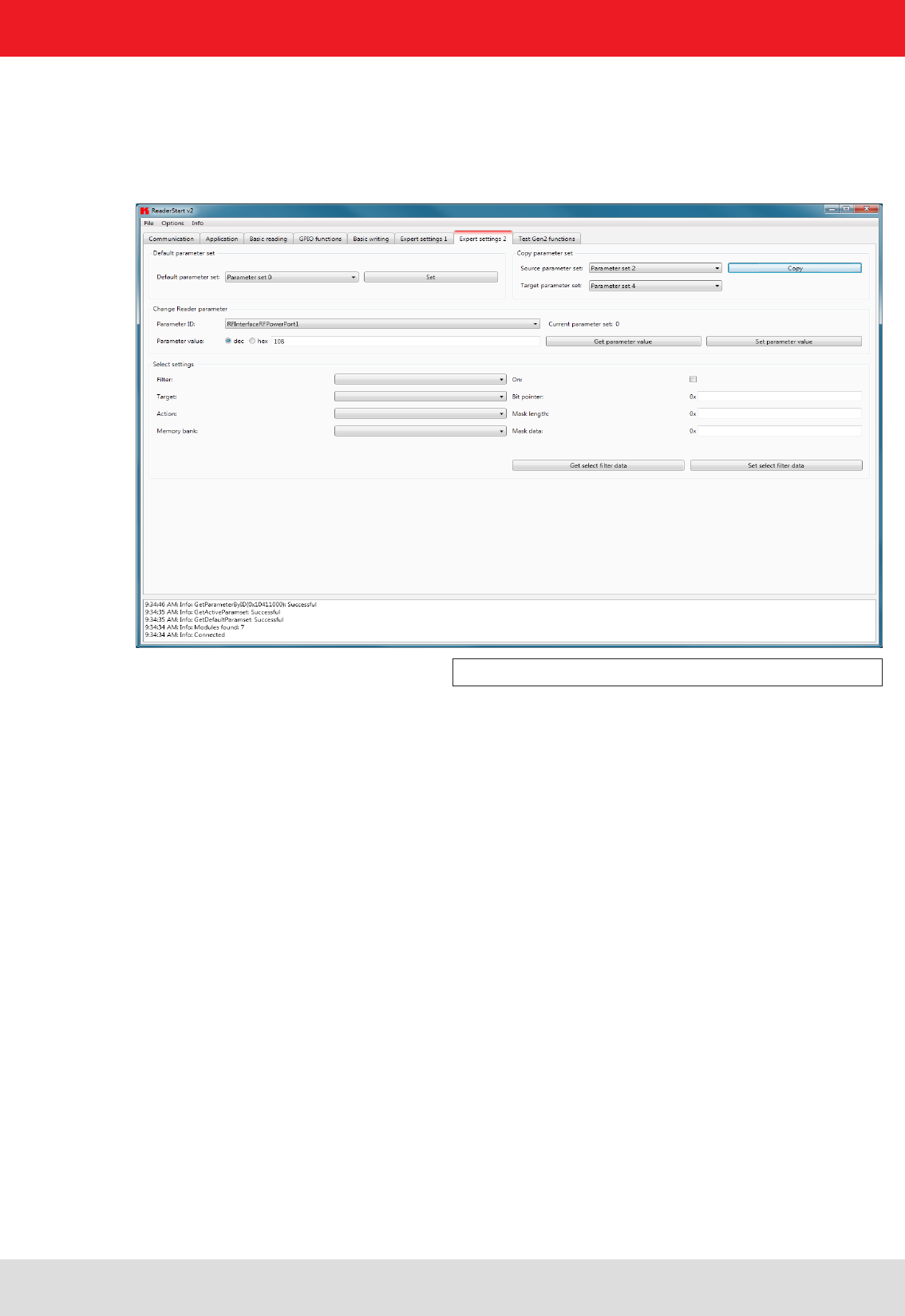
6.4.2. Expert settings 2
The Expert settings 2 tab is split into four headings for further confi guration of the Kathrein RRU4 reader. The default
parameter set can be changed, one parameter set copied into another,reader parameters read to determine their ID
and select fi lter settings confi gured.
Figure: Expert settings 2 tab
The Default parameter set rubric allows confi guration of the parameter set that is loaded from the EEPROM into the
RAM when the Kathrein RRU4 reader is started.
The Copy parameter set header allows one parameter set to be copied into another. On successful completion of the
copy operation, the Copy button glows green briefl y and a corresponding message is displayed in the status window,
otherwise the Copy button glows red.
The Change reader parameter header allows all the Kathrein RRU4 reader settings to be changed using their
respective confi guration IDs. After selection of the parameter ID, the corresponding value of the current parameter set
of the Kathrein RRU4 reader is read by clicking on Get parameter value and displayed in the fi eld parameter value,
optionally as a decimal (dec) or hexadecimal (hex) value. A value that has already been read can be converted to dec
or hex by pressing the radio button. The Set parameter value button writes the value stated in the Parameter value
fi eld into the selected parameter ID. The two actions (read and set) are shown by the respective buttons glowing
the respective colour to indicate success and failure, and a message appears in the status window accordingly.
In the Select settings area, fi lters can be set which are brought into effect by means of a Select command. This
offers the facility to fi lter out certain tags, or to detect only tags with certain defi ned data in the respective
memory banks. Up to 32 fi lters can be set in total. Successful reading of the values of the selected fi lter and
successful writing of the fi lter values is indicated by the respective button glowing green and a text appearing
in the status fi eld. Otherwise the respective button glows red and a description of the error is output.
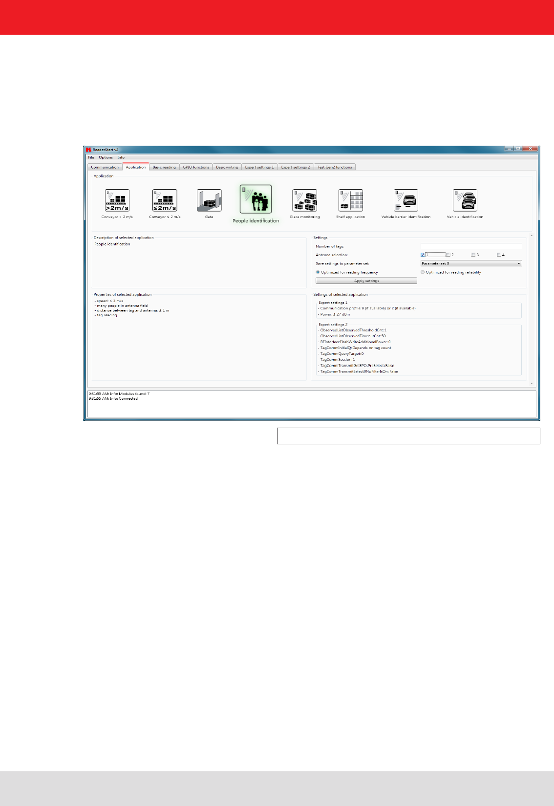
47
6. Operating the reader
6.5. Application
The Application tab enables quick and easy confi guration of the Kathrein RRU4 reader for a selected application. The
available applications are represented visually in the upper area of the tab by labelled pictograms. Under the Settings
header, the number of tags expected, the antennas to be used, the parameter set in which the confi guration should be
saved and the values for max. read frequency and max. read reliability options are stated.
Figure: Application tab
When the button for the desired application is clicked, it glows green continuously. In addition the designation,
the properties and the settings of the selected application are displayed in the respective fi elds.
The following applications are available for selection in version 2.00 of the ReaderStart v2:
• Conveyor belt > 2 m/s
o Application for detecting individual tags in the antenna fi eld on a conveyor belt moving at more than 2 m/s
o the distance between the tags and the antenna is only a few centimetres
• Conveyor belt ≤ 2 m/s
o Application for detecting and describing individual tags in the antenna fi eld on a conveyor belt moving
at less than or equal to 2 m/s
o the distance between the tags and the antenna is only a few centimetres
• Gate
o Application for detecting multiple tags in the antenna fi eld as they pass through a gate
• Slot monitoring
o Application for detecting and describing multiple tags in the antenna fi eld, which are not moving
o the distance between the tags and the antenna should be less than 1 m
• Vehicle identifi cation
o Application for detecting and describing multiple tags in the antenna fi eld, which are moving at more
than 14 m/s
o the distance between the tags and the antenna should be less than a few metres

48
6. Operating the reader
• Vehicle identifi cation (barrier)
o Application for detecting and describing individual tags in the antenna fi eld, which are not moving
o the distance between the tags and the antenna should be less than a few metres
• Shelving application
o Application for detecting and describing very many tags in the antenna fi eld, which are not moving
o the distance between the tags and the antenna should be less than 1 m
• Personal identifi cation
o Application for detecting multiple tags in the antenna fi eld, which are moving at not more than 3 m/s
o the distance between the tags and the antenna should be less than 1 m
If there are more applications than fi t on the screen, the buttons alongside the applications are activated to allow
scrolling.
When the max. read frequency is set, for every detection (inventory) all tags are reset in order to read
them afresh. Under some circumstances the time allowed for detecting the tags may be insuffi cient,
so that some transponders are not detected. The frequency for detecting the tags should then be increased.
When the max. read reliability is set, tags that have already been read are not reset at every detection
(inventory), provided they are still being supplied with power. This means that only those tags which
have not yet been registered are detected. The confi dence that all tags are read is thus increased.
Clicking on the Apply settings button saves the settings that were made, as well as the settings for the selected application,
in the selected parameter set. This is done by fi rst resetting them to the factory settings and thus overwriting the previous
confi guration. This must be acknowledged. Success is indicated by a the Apply settings button glowing briefl y, and by
display of a success message in the status window. If the process fails, the button glows briefl y orange for a warning or briefl y
red for an error (and if the failure was due to an entry being omitted, in addition the fi eld that is lacking the entry glows red),
and by display of a warning description or error description in the status window.
If the settings have been loaded successfully, a switch can now be made to the Basic reading tab and the read process
can be started.
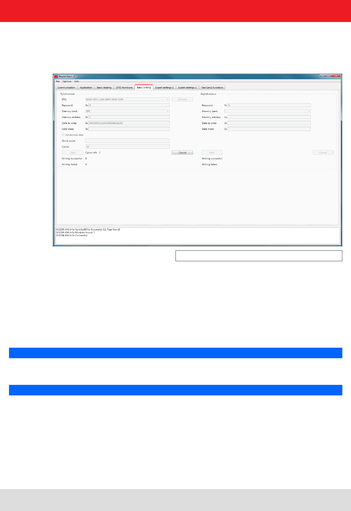
49
6. Operating the reader
6.6. Basic writing function
The Basic writing tab allows input of basic descriptions of tags. A fundamental distinction is maintained between
synchronous writing - write on command - and asynchronous writing - write on arrival.
Figure: Basic write function tab
6.6.1. Synchronous writing
In this type of writing the data can only ever be written selectively to one EPC. This is selected in the EPC ComboBox.
Clicking on the Refresh button detects once again all tags in the antenna fi eld and adds them to the ComboBox.
When all necessary data such as password, memory bank and memory address have been input a decision can
be made whether to specify the data to be written or to generate them at random. If specifi ed data should be
written, optionally a data mask can be specifi ed. When using random data, the number of them should be stated
in words (16-bit).
Note
Right-clicking on the Data to write fi eld opens a context menu, which allows the selected EPC to be copied into this
fi eld.
Note
Right-clicking on the Data mask fi eld allows this to be fi lled optionally with 0 or F according to the number of the data
entered to be written.
Clicking on Start starts the performance of the previously specifi ed number of write attempts. The error-free
completion of all write attempts is once again indicated by the button glowing green and by a message in the status
window. If any necessary data are lacking, the button briefl y glows red and the fi eld lacking the data glows red
somewhat longer. The associated error message appears in the status window.
The Writing successful and Writing failed fi elds indicate how often the write attempt succeeded or failed Hovering the
mouse over the number of failed write attempts (provided indeed any failures did occur), calls up a window with detailed
information.
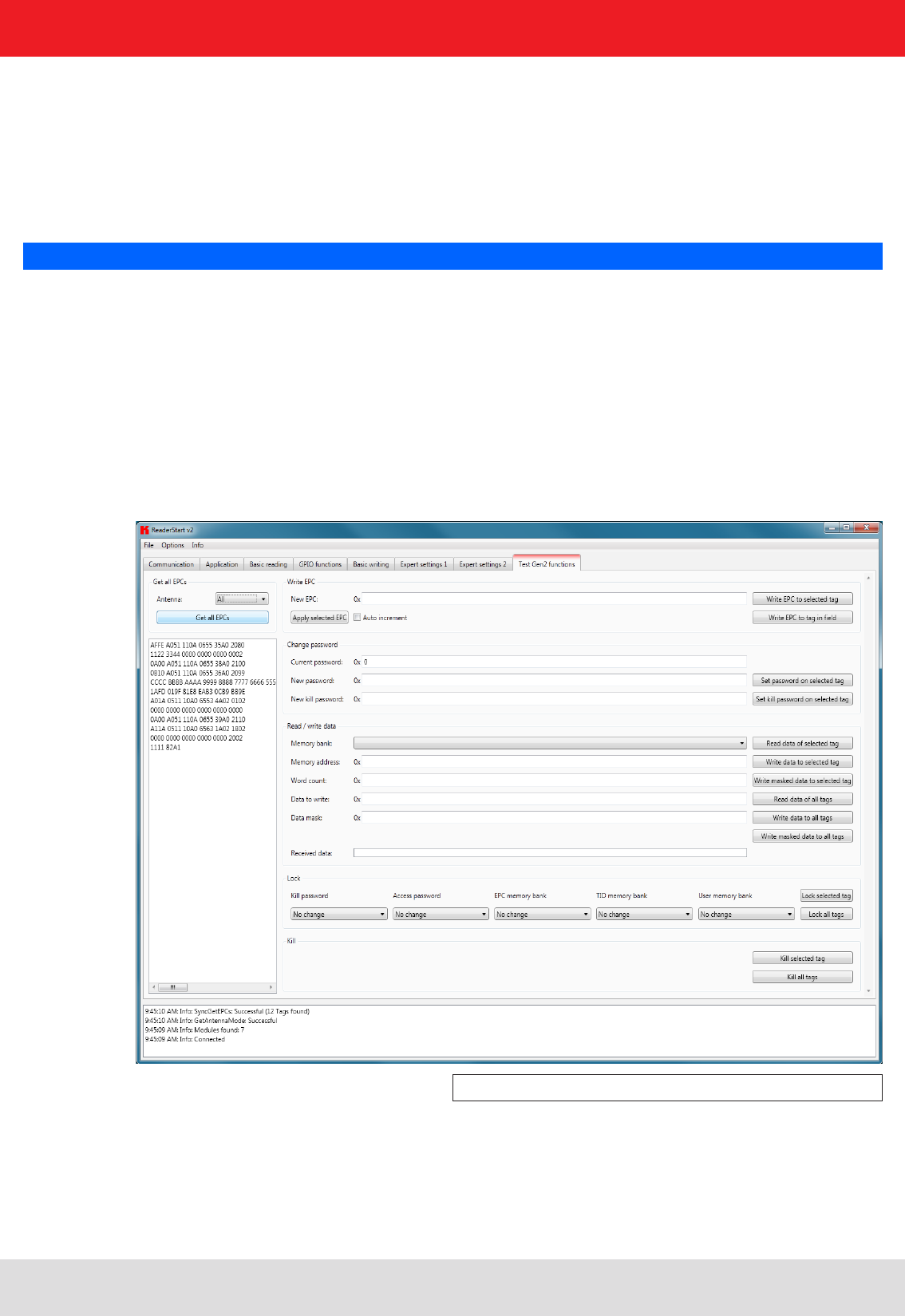
50
6. Operating the reader
6.6.2. Asynchronous writing
In this type of writing the data is written to every EPC that occurs in the antenna fi eld. When all necessary data
(password, memory bank, memory address, data to be described - the input of the data mask is optional) have
been input, clicking on Start starts the asynchronous write process. Successful and failed write attempts are
shown in the respective fi elds. Hovering the mouse over the number of failed write attempts (provided indeed
any failures did occur), calls up a window with detailed information.
Note
Right-clicking on the Data mask fi eld allows this to be fi lled optionally with 0 or F according to the number of the data
entered to be written.
6.7. Test Gen2 functions
This tab makes it possible to access individual functions of the reader. This includes, along with the functionality
in accordance with the EPC-Gen2 standard, e. g.: read individual tags, describe tags, set and change passwords,
and also select the antenna for the operation.
The user interface consists of the headers Get all EPCs, Write EPC, Change password, Read/write data, Lock, Kill
and the display window for EPCs that have been read. The sections that follow explain this functionality in more detail.
Figure: The Test Gen2 functions menu tab

51
6. Operating the reader
6.7.1. Get all EPCs
To read a tag in this menu, the Get all EPCs button must be clicked once the reader has been correctly
confi gured. The reader now tries once again to read all the tags in the fi eld of the selected antenna.
If in the Antenna selection drop-down menu the number of antennas has been restricted, reading will
now be performed using the currently selected antenna, or using the antenna selected with All in the
Expert settings 1.
The EPCs from the tags read successfully are displayed in the fi eld below. For the following operations, a tag can be
selected from this list by clicking on it.
Note
Right clicking on the tag brings up additional information on the manufacturer and the chip type.
6.7.2. Write EPC
The EPC of the tag can be altered as desired under this header. For this purpose an EPC in hexadecimal format
must be entered in the New EPC fi eld.
Note
Comply with the maximum EPC length supported by the tag - if this is exceeded the tag will return an error.
If the requirement is only to amend an existing tag, this tag can be loaded to the fi eld by pressing the Apply selected
EPC button. Now the EPC can be changed manually, or by using the Auto increment option can be increased by one
at each write event.
The write event itself can optionally be executed on this tag by pressing the Write EPC to selected tag button. At this
time there may be several tags in the fi eld, but at least one tag from the list must be selected. The second option is to
write the specifi ed EPC without a tag being selected. When using this function, make sure there just one single tag in
the fi eld.
6.7.3. Change password
The EPC standard (see (B)) specifi es that the tag should have two modes, the open and the secured state.
In the open state, operations can be performed on the tag if the associated memory areas are not secured with
a password greater than 0. If a password has been set and the Lock header has been used to set the memory
areas to password protected, the desired operation will not be executed, and the tag will report an access error.
Normal access remains available in areas that are not blocked.
If when the tag is accessed the valid password is given, the tag switches into the secured state and access is available
even in blocked areas. Setting the password and setting how individual areas are blocked is performed under the
Change password and Lock headers.
Under the fi rst header, the password for restricting access to the tag and the password for deactivation of the
tag are set. The access password can be used to restrict access to the tag in the open state. Depending on the
confi guration under the Lock header, parts of the tag can be provided with completely or partially restricted access
rights.
The deactivation password is required to deactivate the tag permanently by means of a Kill command.
Note
After a Kill tag command, the tag will be unusable.
To change the password, the current password must be given. If no password has yet been set, the
default value is 0. The new password is entered in the fi eld of the same name, in hexadecimal format.
Clicking on the Set password on selected tag button replaces the old password with the new password.
The deactivation password is entered in the fi eld of the same name by clicking on the associated button.
If the password is changed and the memory area in question is already protected by the access password, in addition
to the new password the access password must be entered in the Current password fi eld.

52
6.7.4. Read/write data
This header supplies detailed access to all the data areas of the tag. Access is obtained by entering the selected
memory bank, the address within the memory bank and the number of words, expressed as 16-bit words.
If data are to be written, they must be entered in the Data to write fi eld. The data mask allows only
individual bits on the tag to be changed. To do this, the mask must be entered in the Data mask fi eld. The
reader uses this mask to change the data read from the tag at the points where 1 bits are written in the
mask, and writes the result back into the tag. The desired data can optionally be written to a single tag
in the fi eld or to all tags in the fi eld. If they are written to all tags in the fi eld, these tags must all have the same
confi guration (lock and password).
The header also offers the facility to read data from the selected tag or from all tags in the fi eld. If the tags in the
fi eld have differing passwords and are confi gured differently, the data must be read by individual tags.
The next section deals in more detail with the saving of the individual memory areas.
6. Operating the reader
6.7.5. Lock
The EPC Gen 2 standard provides security mechanisms for the tag data areas. This allows individual memory areas
and functionalities of the tags to be provided with a password to protect it against access and/or changes.
Under the Lock header, the mask that specifi es access to the areas in accordance with the EPC Gen 2 standard can be
customised to suit the application. If no changes are required for an area, No change must be selected in the respective
drop-down menu. The areas are grouped as follows:
1 Deactivate – specifi es whether or not a deactivation password is necessary for deactivating the tag. Further
details can be found in (B).
2 Access – specifi es whether an access password is necessary for accessing a tag. If no access password is set,
the TAG can be addressed in the open state condition. Further details can be found in (B).
3 EPC – allows specifi cation of whether or not the access password is necessary for changing the EPC.
4 TID – this area contains general information about the tag. This area can also be protected against user access
by setting the access password.
5 USER – if the tag has a memory area provided for user data, these can be protected by setting the access
password.
The respective items in the drop-down menu are divided into access blocks, which prevent reading and writing, and
write blocks.
Note
If the option with the suffi x is permanently selected, this option can no longer be changed. Further details can be
found in (B).
Clicking on the Lock selected tag button loads the mask that was created to the list of the selected
tag. Alternatively all the tags in the fi eld can be blocked, on the precondition that the tags all have the
same password.
Note
Wrongly confi guring the Lock header can render the tag unusable.

53
6. Operating the reader
6.7.6. Kill
Pressing the Kill selected tag button, with the stated password, executes a Kill command on this tag. The Kill all tags
button, with the stated password, attempts to execute a Kill command on all the tag in the fi eld.
Note
For the deactivation of a tag, a deactivation password that is not 0 must have been set.
Note
After a Kill tag command, the tag will be unusable.

54
7. Reader configuration
The RRU4 Kathrein UHF RFID reader system is characterised by great fl exibility in addressing RFID applications.
One reason for this is the wide variety of reading devices from the Kathrein product portfolio, which are compatible
with each other and permit optimum confi guration to the application. A further reason for the high fl exibility
is the wide range of parameters for confi guring the reader fi rmware. This confi guration manual explains the
various confi guration parameters and give instructions on how to make the optimum parameter settings for the
application of your Kathrein RFID reader.
7.1. Introduction
A confi guration parameter of the RRU4 reader system consists of a 32-bit long identifi cation number (ID) and a
data part which is 8 to 32 bits depending on the parameter. The data part is referred to below as the “parameter
value” or just the “value”. The ID allows the various parameters to be read or set in the reader system.
Each ID – and hence each confi guration parameter – stands for a special functionality within the reader system.
7.1.1. Structure of the confi guration IDs
The ID of a confi guration parameter is not selected arbitrary, rather it contains information about the respective
confi guration parameter. The ID of a confi guration parameter contains the following information:
- the confi guration group to which the parameter belongs
- a sequential number to differentiate parameters within a group
- the data type (byte, word, etc.) of the value
- the number of data bytes in the value
- whether the value of the parameter is signed (are negative values possible)
- the unit of the value
For ease of handling the confi guration parameters are addressed by their plain text names. The plain text name
begins with “cfgid” followed by the name of the confi guration group. This includes the function name of the
parameter. That is the part that clearly states the function/use of the confi guration parameter. For example:
Confi guration parameter “cfgidTagCommIntelligentWrite”
“cfgid” initial code
“TagComm” Name of the confi guration group
“IntelligentWrite” Function name of the parameter
For more details about the structure of the ID or the naming of confi guration parameters, see the fi le “konfi gids.h” in
the source fi les for the programming environment of the RRU4 reader system.
For programmers: This fi le contains macros in the programming language “C”, which offers you the facility in your
programming environment to address the confi guration parameters by their plain text names. The plain text name is
then translated into the respective confi guration ID at compile time.
7.1.2. The parameter sets
The confi guration of an RFID reader of the RRU4 reader system is organised in parameter sets. Each reader has
eight parameter sets. Apart from one exception (“cfgidGlobalDefaultParamset”) all the confi guration parameters
listed below are represented in every parameter set. The use of parameter sets allows an RFID reader to switch
from one confi guration to another with only one command. The parameter set selected is then designated
the “active parameter set”. Reading and writing confi guration parameters using the protocol commands
“GetParameterById” and “SetParameterById” is always performed on the active parameter set. When the active
parameter set is changed it can be saved into the reader's EEPROM using “SaveActiveParamset”, and thus is
available again when the reader is restarted. Changing over between parameter sets is performed using the
command “SetActiveParamset”.

55
7. Reader configuration
7.2. Description of the confi guration parameters of the RRU4 reader system
7.2.1. The “Global” confi guration group
7.2.1.1. “DefaultParamset”
Characteristics:
available from fi rmware: v1.30.00
Data type: Byte (8-bit)
Unit: –
Value range: 0-7
Description:
This parameter is the only one in its confi guration group. In contrast to all the other parameters, this one is
“independent”. That means that this parameter is not held in any parameter set, it just exists on its own. The parameter
indicates which parameter set is loaded and activated when the reader is started up.
7.2.2. The confi guration group “RFInterface”
7.2.2.1. “RFPower1...8”
Characteristics:
available from fi rmware: v1.30.00
Data type: Byte (8-bit)
Unit: ¼ dBm(erp)
Value range: 0; 68-136
Description:
This parameter allows the reader transmission power to be set for respective antenna port. More precisely: The
power which the antenna should radiate. The data is given in dBm(erp). So that the power radiated by the antenna
really does correspond to the value of this parameter, the parameters for the attenuation of the antenna cable
and the antenna gain must be set correctly.
It is a precondition that the transmission power is set to a value greater than 0 dBm(erp), in order that an inventory
can be performed using this antenna port.
Note
The transmission power is always set in dBm(erp). If the desired transmission power is stated in dBm(eirp),
this must be converted to dBm(erp): dBm(erp) = dBm(eirp) - 2.14

56
7.2.2.2. “TimeToPowerOff”
Characteristics:
available from fi rmware: v1.30.00
Data type: Word (16-bit)
Unit: Seconds
Value range: 0-65535
Description:
This parameter sets the duration for how long the transmission carrier remains switched on after the completion of
an inventory, or a tag operation in general.
A certain time must elapse after receipt of an inventory command before the reader can start the inventory. This
time is required by the reader amongst other things for LBT (Listen before Talk) and for an antenna test. Using this
parameter it is now possible to reduce this time: If an inventory has been completed by the reader, and the next
inventory command is received within the time confi gured by this parameter, the reader can dispense with the LBT and
the antenna test and start the inventory more quickly.
7. Reader configuration
Note
The time during which the transmission carrier is switched on by not performing any tag operation represents an
increase in the overall power consumption of the reader.
The LBT (Listen Before Talk) operating mode is permissible only in existing systems.
7.2.2.3. “ModulationType”
Characteristics:
available from fi rmware: v1.30.00
Data type: Byte (8-bit)
Unit: -
Value range: 0; 1
Description:
This parameter is used by the reader to specify the modulation type used for tag communication.
There are two modulation types available:
0: Double Side Band (DSB)
1: Phase Reversal Amplitude Shift Keying (PR-ASK)
Note
For readers manufactured for the European Union (EU), Phase Reversal Amplitude Shift Keying is used
irrespective of the setting of this parameter.
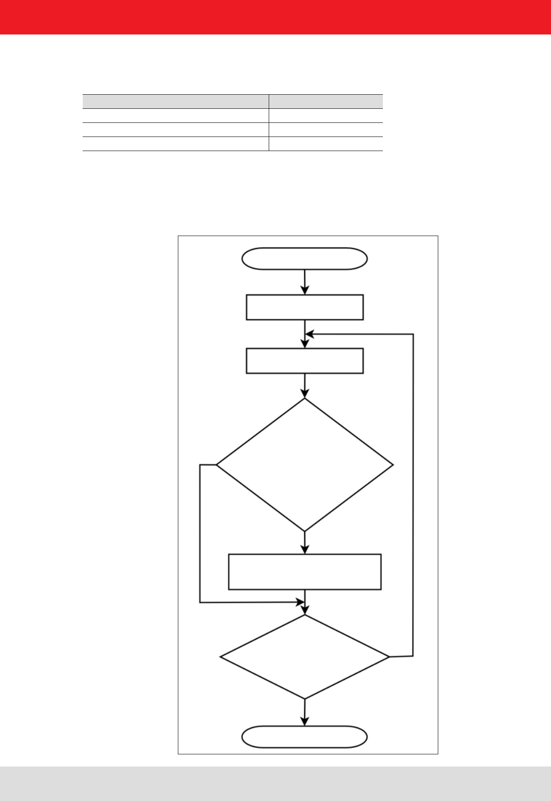
57
7. Reader configuration
7.2.2.4. “MultiplexingAntennaport1...8”
Characteristics:
available from fi rmware: v1.30.00
Data type: Byte (8-bit)
Unit: -
Value range: 0; 1-8
Description:
These eight parameters form the antenna multiplex list of the reader. Either an antenna port number (1 to 8) or a
zero can be entered in each of the eight list slots. If a zero is entered, the list slot is deactivated and the reader
skips to the next list slot. This is shown in the following diagram:
Inventory start
Index multiplex list := 0
Index multiplex list +1
no
yes
yes
no
Does the multiplex list
contain an entry and is
there a power confi gured
for this antenna port?
Perform inventory at a
specifi ed antenna port
Has the end of the
multiplex list been
reached?
Inventory end

58
7. Reader configuration
7.2.3. “MultiplexingExposureTime1...8”
Characteristics:
available from fi rmware: v1.30.00
Data type: Word (16-bit)
Unit: milliseconds
Value range: 0-65535
Description:
The values of these confi guration parameters are of interest only to reader commands that start with “ASync...”.
Each parameter stands for an exposure time which specifi es how long the reader maintains exposure for inventories
the respective position – and hence antenna – in the multiplex list. In contrast to synchronous commands, when
using asynchronous commands the reader does not proceed to the next entry in the multiplex list immediately
after performing an inventory; instead it fi rst waits until the exposure time given by these parameters for the
respective multiplex entry has expired. An inventory in progress is not interrupted at the expiry of the exposure time,
but is continued to completion.
7.2.3.1. “CableLoss1...8”
Characteristics:
available from fi rmware: v1.30.00
Data type: Byte (8-bit)
Unit: ¼ dB
Value range: 0-255
Description:
These parameters contain the cable attenuation of the antenna cable between the reader and the antenna for the
respective antenna port of the reader. The reader can set the transmission power correctly only if the attenuation
values for the antenna cable have been entered correctly.
7.2.3.2. “AntennaGain1...8”
Characteristics:
available from fi rmware: v1.30.00
Data type: Byte (8-bit); signed
Unit: ¼ dBic
Value range: -128 – 127
Description:
These parameters allows the antennas gain for the antennas connected to the reader to be communicated to the
reader. The reader calculates from the transmission power setting (antenna radiated power), the antenna gain
and the cable attenuation the port power at the RF output:
Use the following formula to convert an antenna gain expressed in dBi to dBic units:
Antenna gaindBic = antenna gaindBi + 3
Port powerdBm = radiated powerdBm(erp) – antenna gaindBic + cable attenuationdB + 5.14
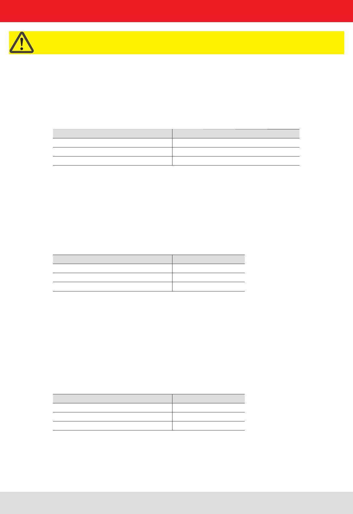
59
7. Reader configuration
Important!
Close fi eld antennas have a negative gain, since they are designed not for electromagnetic coupling with the
tag but for magnetic coupling. To confi gure close fi eld antennas correctly, enter the antenna gain as 5.25 dBic
(a parameter value of 21 dec) and the antenna radiated power (“RFPower1...8”) as the maximum input power stated
in the antenna data sheet.
7.2.3.3. “RSSIThreshold1...8”
Characteristics:
available from fi rmware: v1.30.00
Data type: Byte (8-bit)
Unit: -
Value range: 0; 255
Description:
When the reader is performing an inventory, at the same time the fi eld strength of the response from the tag that is
addressed is measured. This is called the RSSI value. These parameters allow the threshold value for the RSSI value
to be set for each antenna port. Tags with an RSSI value less than the threshold setting are then no longer detected
by the reader.
7.2.3.4. “MultiPowerTagAccess1...8”
Characteristics:
available from fi rmware: v1.30.00
Data type: Bool (8-bit)
Unit: -
Value range: 0; 255
Description:
The stronger the reader transmission signal that strikes the tag, the more diffi cult it is for the tag to modulate the
reader transmission signal by means of backscatter. The strength of the tag response thus decreases as the reader
transmission power increases. Because of this behaviour in certain circumstances it may occur that the reader can
no longer read a tag which is immediately in front of the antenna, but at a lower transmission power it can easily
detect it. If “MultiPowerTagAccess” is activated for an antenna port, after an inventory with high transmission power,
the reader reduces the transmission power by a half and searches for “overlooked” tags.
7.2.3.5. “MaxAllowedAntennaOutputPower1...8”
Characteristics:
available from fi rmware: v1.30.00
Data type: Byte (8-bit)
Unit: ¼ dBm(erp)
Value range: 0-255
Description:
This parameter allows the radiated power of the antenna at an antenna port to be limited to a specifi ed value.

60
7. Reader configuration
7.2.3.6. “EnableRSSIThresholdAtSpecifi cCmds”
Characteristics:
available from fi rmware: v1.46.00
Data type: Bool (8-bit)
Unit: –
Value range: 0; 255
Description:
The RSSI threshold value set by the “RSSIThreshold1...8” parameter applies equally to non-specifi c (“...GetEPCs”,
“...Any”) and specifi c (“...Specifi c”) tag reader commands. The effect on specifi c tag reader commands can however
be switched on and off by these confi guration parameters. The following scenario can be set: “SyncGetEPCs”
commands the reader to scan cyclically for tags in the antenna fi eld. The confi guration parameter “RSSIThreshold1...8”
means that tags with less than a specifi ed RSSI value are not reported. One tag is now close to the RSSI
threshold and when the threshold is reached is reported by the reader to the higher level. This triggers a specifi c
command for the reported tag. If “EnableRSSIThresholdAtSpecifi cCmds” is activated it can now happen that the
specifi c command comes to nothing, since the RSSI value of the tag is fl uctuating around the threshold value.
In such a scenario, “EnableRSSIThresholdAtSpecifi cCmds” should be deactivated.
7.2.3.7. “FlashWriteAdditionalPower”
Characteristics:
available from fi rmware: v2.00.00
Data type: Byte (8-bit)
Unit: ¼ dB
Value range: 0-48
Description:
It takes more energy to write to a tag than to read a tag. Therefore for a given transmission power the tag must
be nearer the antenna for writing than for reading. In order to overcome this distance differential, this parameter
can be used to specify whether and by how much the reader transmission power needs to be increased
for write commands compared to read commands.
7.2.4. The confi guration group “Tag communication” (“TagComm”)
7.2.4.1. “UsePilottone”
Characteristics:
available from fi rmware: v1.30.00
Data type: Bool (8-bit)
Unit: –
Value range: 0; 255
Description:
This parameter allows the pilot tone tag to be switched on and off. Tags to EPCGlobal Class 1 Gen 2 are able to
carry a pilot tone ahead of the user data. The purpose of the pilot tone is the synchronisation of the reader to the
response of the tag. Without a pilot tone it is more diffi cult for the reader to synchronise itself to the tag response.
In order to ensure reliable tag detection, this parameter should always be activated.

61
7. Reader configuration
7.2.4.2. “InitialQ”
7.2.4.3. “Session”
Characteristics:
available from fi rmware: v1.30.00
Data type: Byte (8-bit)
Unit: –
Value range: 0-3
Description:
Tags to EPCGlobal Class 1 Gen 2 support four different “sessions”. At each session a tag can be given an inventoried
fl ag to indicate whether or not it has already been detected by the reader during an inventory process. Inventoried
fl ags have different properties for the individual sessions, which allows recognition of their persistence times.
The time thus indicates how long a tag indicates that it has been detected or not by the reader.
Tag has energy Tag has no energy
Session 0 unlimited persistence no persistence
Session 1 persistence greater than 500 milliseconds
but less than 5 seconds
persistence greater than 500 milliseconds but less than
5 seconds
Session 2 unlimited persistence persistence greater than 2 seconds
Session 3 unlimited persistence persistence greater than 2 seconds
This confi guration parameter instructs the reader the session with which it should work.
Characteristics:
available from fi rmware: v1.30.00
Data type: Byte (8-bit)
Unit: –
Value range: 0-15
Description:
The value Q in the inventory process specifi es how many tags there are in the reader antenna fi eld and which must
be detected. The number x on tag is calculated by the following formula:
The value Q is communicated to the tags by the reader, whereupon each of these selects from x a random
“Communications slot” for its response. In order to perform an inventory as quickly and effi ciently as possible, as
many of the x communications slots should be occupied by tags, but without there being any multiple occupation
of communications slots (which would lead to collisions). If the reader detects that the value chosen for Q is
too large (hardly any communications slots are occupied) or too small (collisions occur), it will be adjusted
automatically and loaded to the tags. Since this adjustment takes time, the reader with this confi guration parameter
should be informed of the approximate number of tags to expect in the antenna fi eld. This allows the number
of communications slots to be set to an appropriate value right from the start of the inventory process.
-1

62
7.2.4.4. “MaxErrors”
Characteristics:
available from fi rmware: v1.30.00
Data type: Byte (8-bit)
Unit: –
Value range: 0-255
Description:
The “MaxErrors” confi guration parameter indicates how often a command is issued by the reader to the tag when
the response expected by the reader from the tag remains outstanding.
7. Reader configuration
7.2.4.5. “CommunicationProfi le”
Characteristics:
available from fi rmware: v1.30.00
Data type: Byte (8-bit)
Unit: –
Value range: 0-255
Note: Up to fi rmware v2.04.00 this parameter was called “DefaultProfi le”.
The confi guration ID was not changed.
Description:
This confi guration parameter sets the “communication profi le” between the reader and tag. A communication profi le
consists of:
- the data transmission rate (reader to tag communication)
- the data reception rate ( tag to reader communication)
- the coding of the data from tag to reader
There are various data transmission rates, data reception rates and codings available. Since not every combination
of these three properties is viable, selected combinations are available as communication profi les. A list of the
viable communication profi les can be downloaded from the reader by the command “GetProfi leList”. It is dependent
on the selected communication profi le whether “Dense Reader Mode” is in operation in the reader or not.
7.2.4.6. “CommStandard”
Characteristics:
available from fi rmware: v1.30.00
Data type: Byte (8-bit)
Unit: –
Value range: 0-255
Description:
Different countries have different regulations regarding the permissible transmission power and transmission
channels that can be used for communication with RFID tags. This confi guration parameter informs the reader
which regulations to comply with for radio communication with RFID tags.
For more details on the country profi les that are supported, see the fi le “rrui4api.h” in the source fi les for the
programming environment of the RRU4 reader system.

63
7. Reader configuration
7.2.4.7. “IntelligentWrite”
Characteristics:
available from fi rmware: v1.30.00
Data type: Bool (8-bit)
Unit: –
Value range: 0; 255
Description:
Depending on the type of tag, it requires 10 to 20 milliseconds time to write 16 bits of data (one word). If for instance
a 96-bit EPC should be written, then the time which a tag requires for saving the data is 120 milliseconds in the
worst case. Only a fi fth to a tenth of this time would be required for reading the data from a tag. In practice it often
happens that the data written to a tag were already present on it. Despite this, the tag requires the full stated time
to complete the write command. This confi guration parameter should be activated in order to accelerate the write
event and to avoid writing data when they are already present on the tag. To achieve this, before writing to the tag
the reader fi rst reads the relevant data area on the tag. It then writes only those parts which it is necessary to change.
Note: If a memory area on a tag is protected by a “Lock” against overwriting, and if identical content is scheduled
to be written to the tag with “IntelligentWrite” activated, no error message is generated by the reader. No write
command is issued to the tag in the process of reading the existing data, comparing it with the data to be written
and establishing by the reader that no changed data need be written to the tag. With no write command issued,
the reader is not in the position to detect the “Lock” on the memory area.
7.2.4.8. “VerifyWrite”
Characteristics:
available from fi rmware: v1.30.00
Data type: Bool (8-bit)
Unit: –
Value range: 0; 255
Description:
After a write operation, a tag sends the result to the reader. This result can be either an error code or a success
message. The memory cells of a tag cannot be written infi nitely many times, since they are subject to ageing.
Depending on the tag, it has a working life of 1,000 to 1,000,000 write cycles. At the end of a tag's working life it
can occur that following a write operation a tag sends out a success message to the reader, but has not stored
the data correctly in the tag memory. If “VerifyWrite” is activated, the reader issues a read command after receiving
the success message. This reads the data in the tag memory and reports any mismatches to the higher level
as “Verify Fail”.
Important!
Even with “VerifyWrite” activated, there is no guarantee that the data are stored correctly in the tag memory.
Aged tags may “forget” the content of their memory, be it minutes or hours after the write operation!

64
7. Reader configuration
7.2.4.9. “QueryTarget”
Characteristics:
available from fi rmware: v1.30.00
Data type: Bool (8-bit)
Unit: –
Value range: 0; 255
Description:
Tags to EPCGlobal Class 1 Gen 2 support four different “sessions”. At each session a tag can be given an inventoried
fl ag to indicate whether or not it has already been detected by the reader during an inventory process. The status of
the inventoried fl ag can be either “A” or “B”. When the tag is detected in the inventory, the status of the fl ags switches
either from A to B or from B to A. The status of the fl ag can also be infl uenced by “Select commands”.
The confi guration parameter “QueryTarget” determines which tags should participate in the inventory. If the
confi guration parameter has the value zero, the tags participate in the inventory for which the inventoried fl ag is
set to A.
Otherwise only the tags for which the inventoried fl ag is set to B. In conjunction with the “Select fi lters”, fi lter tasks
can be performed in this way.
Note
See also the “EPCglobal Class 1 Generation 2 UHF RFID” specifi cation V1.2.0 section 6.3.2.2 (page 43f).
7.2.4.10. “QuerySel”
Characteristics:
available from fi rmware: v1.30.00
Data type: Byte (8-bit)
Unit: –
Value range: 0-3
Description:
This confi guration parameter specifi es the content of the fi eld “Sel” in the Gen2 command “Query”. This fi eld instructs
the tag whether the content of the “Selected fl ag” is or is not relevant for participation in the inventory. In conjunction
with the “Select fi lters”, fi lter tasks can be performed in this way.
Note
See also the “EPCglobal Class 1 Generation 2 UHF RFID” specifi cation V1.2.0 section 6.3.2.11.2.1 (page 57).

65
7. Reader configuration
7.2.4.11. “ForcePowerOffAfterEPCWrite”
Characteristics:
available from fi rmware: v1.40.00
Data type: Byte (8-bit)
Unit: milliseconds
Value range: 0-255
Description:
During the inventory process a tag transmits its EPC and a checksum to the reader. This checksum is formed when
the tag is “Powered up” from the memory area of the EPC. If now a write command changes the EPC and a new
inventory is started without any intervening “Power up” – i.e. without switching off the antenna fi eld, the tag cannot
participate in the inventory, because the checksum it communicates no longer matches the EPC it transmits.
This confi guration parameter specifi es whether and for how long after a write operation to the memory bank of the EPC
the carrier should be switched off so as to “repower” the tag.
Note
See also the “EPCglobal Class 1 Generation 2 UHF RFID” specifi cation V1.2.0 section 6.3.2.1.2.1 (page 38).
7.2.4.12. “TransmitGetEPCsPreSelect”
Characteristics:
available from fi rmware: v1.41.00
Data type: Bool (8-bit)
Unit: –
Value range: 0; 255
Description:
The content of this confi guration parameter affects only the protocol commands “SyncGetEPCs”,
“SyncBulkGetEPCs”, “ASyncGetRawEPCs” and “ASyncGetEPCs”. All other protocol commands behave as if
“TransmitGetEPCsPreSelect” is zero. Depending on the value of this confi guration parameter, an inventory runs
as follows:
• “TransmitGetEPCsPreSelect” is zero:
1. the fi rst antenna is selected from the multiplex list
2. a Select to reset all tags within the reception range of the selected antenna is executed
3. an inventory is executed by the selected antenna, until no further tags are found
4. as long as there remain further antennas in the multiplex list, the next antenna is selected and the process
resumes at point 2
5. the protocol command is completed and the result is transferred to the higher level
• “TransmitGetEPCsPreSelect” is not equal to zero:
1. the fi rst antenna is selected from the multiplex list
2. a Select to reset all tags within the reception range of the selected antenna is executed
3. as long as there remain further antennas in the multiplex list, the next antenna is selected and the process
resumes at point 2
4. the fi rst antenna is selected from the multiplex list
5. an inventory is executed by the selected antenna, until no further tags are found
6. as long as there remain further antennas in the multiplex list, the next antenna is selected and the process
resumes at point 5
7. the protocol command is completed and the result is transferred to the higher level

66
If several antennas look at a population of tags and it is immaterial which antenna detects any tag, the time for a
complete detection of the tag population can be reduced by activation of this confi guration parameter: Tags which
had already been detected by one antenna are no longer detected by the following antennas in the multiplex list.
7.2.4.13. “TransmitSelectIfNoFilterIsOn”
Characteristics:
available from fi rmware: v1.45.00
Data type: Bool (8-bit)
Unit: –
Value range: 0; 255
Description:
At the start of an inventory the reader sets all tags that are within antenna range to a defi ned initial status, using
a defi ned “select fi lter” or a “select” command. The subsequent inventory then detects all tags that are in this
defi ned initial status. If no select fi lters were defi ned, this confi guration parameter can be used to specify whether
or not before the inventory a select command should be sent to perform a global reset of all tags within the
antenna range.
7. Reader configuration
7.2.4.14. “NumberOfEPCWords”
Characteristics:
available from fi rmware: v2.00.00
Data type: Byte (8-bit)
Unit: –
Value range: 0-31; 255
Description:
From fi rmware version v2.00.00, RRU4 RFID readers of the Kathrein reader system can read tags with an EPC length
of 0 to 31 words (0 to 496-bit EPCs). This parameter allows deactivation of the automatic detection of the EPC length,
thus forcing the reader to work with a fi xed length.
7.2.4.15. “UseBlockWrite”
Characteristics:
available from fi rmware: v2.00.00
Data type: Bool (8-bit)
Unit: –
Value range: 0; 255
Description:
If this confi guration parameter is activated, the reader uses the command “BlockWrite” for writing data to a tag.
This means that more than 16 bits (one word) can be written to a tag with just a single command and thus save
“write time”.
Note
Not all tags support the command “BlockWrite”. See also the “EPCglobal Class 1 Generation 2 UHF RFID”
specifi cation V1.2.0 section 6.3.2.11.3.7 (page 74).

67
7. Reader configuration
7.2.4.16. “DisableReceivingNXPReadProtectedTags”
Characteristics:
available from fi rmware: v2.01.00
Data type: Bool (8-bit)
Unit: –
Value range: 0; 255
Description:
If a tag from the company NXP was protected by “ReadProtect”, at inventory it would no longer communicate
its EPC or a valid checksum. The data content of the EPC and the checksum is zero. To allow such tags to be
detected, the reader allows tags for which the EPC and checksum are zero to pass. Since such tags are no
longer secured with a valid checksum, it can happen very occasionally that the reader detects such a tag where
none exists. In order to prevent this, the reception of “ReadProtected” tags can be suppressed by activation of this
confi guration parameter.
7.2.5. The confi guration group “ObservedList”
7.2.5.1. “GlimpsedTimeoutCnt”
Characteristics:
available from fi rmware: v1.30.00
Data type: Byte (8-bit)
Unit: –
Value range: 0-255
Description:
This confi guration parameter applies only to asynchronous protocol commands (“ASync...”). For the duration
of an asynchronous command, the reader compiles a list of all the tags found within the antenna range. If a tag
is present in the antenna range for multiple inventories, a “coming” message is generated for that tag and the
message is sent to the higher level. If a tag is no longer detected during multiple inventories, a “going” message is
generated and sent.
Once the “going” message has been generated for a tag, this confi guration parameter specifi es the number of
inventories where the tag is not detected, which then triggers deletion of this tag from the internal administration list.
This parameter should not be changed. It has no infl uence over the generation of a “coming” or “going” message.
Kathrein reserves the right to remove this parameter from fi rmware versions at a future point in time.
7.2.5.2. “ObservedThresholdCnt”
Characteristics:
available from fi rmware: v1.30.00
Data type: Byte (8-bit)
Unit: –
Value range: 0-255
Description:
This confi guration parameter applies only to asynchronous protocol commands (“ASync...”). For the duration
of an asynchronous command, the reader compiles a list of all the tags found within the antenna range. If a tag
is present in the antenna range for multiple inventories, a “coming” message is generated for that tag and the
message is sent to the higher level. If a tag is no longer detected during multiple inventories, a “going” message is
generated and sent.
This confi guration parameter specifi es the number of inventories where the tag is detected, which then triggers the
generation of a “coming” message which is sent to the higher level.

68
7. Reader configuration
7.2.5.3. “ObservedTimeoutCnt”
Characteristics:
available from fi rmware: v1.30.00
Data type: Byte (8-bit)
Unit: –
Value range: 0-255
Description:
This confi guration parameter applies only to asynchronous protocol commands (“ASync...”). For the duration
of an asynchronous command, the reader compiles a list of all the tags found within the antenna range. If a tag
is present in the antenna range for multiple inventories, a “coming” message is generated for that tag and the
message is sent to the higher level. If a tag is no longer detected during multiple inventories, a “going” message is
generated and sent.
This confi guration parameter specifi es the number of inventories where the tag is no longer detected, which then
triggers the generation of a “going” message which is sent to the higher level.
7.2.6. The confi guration group “Host communication” (“HostComm”)
7.2.6.1. “ExtendedResultFlag”
Characteristics:
available from fi rmware: v1.30.00
Data type: Byte (8-bit)
Unit: –
Value range: 0-15
Description:
This confi guration parameter allows specifi cation of which additional information on a tag should be sent when tag
data are sent to the higher level. Every bit of the lower four bits that is set to “1” in this confi guration parameter
causes the sending of certain additional information:
Bit 0: Sending the antenna information (the antenna which detected the tag)
Bit 1: Sending the RSSI value (fi eld strength information of the tag response)
Bit 2: Sending the time stamp (the time when the tag was detected)
Bit 3: Sending the protocol control word of the tag (PC, [XPC_W1, [XPC_W2]]; see also the “EPCglobal Class 1
Generation 2 UHF RFID” specifi cation V1.2.0 section 6.3.2.1.2 (page 38).)
7.2.6.2. “AntennaIndependentOperation”
Characteristics:
available from fi rmware: v1.30.00
Data type: Bool (8-bit)
Unit: –
Value range: 0; 255
Description:
This confi guration parameter allows differentiation between “antenna-dependent” (confi guration parameter
deactivated) and “antenna-independent” (confi guration parameter activated) operation of the reader.
This confi guration parameter is relevant to all asynchronous protocol commands (“ASync...”) and to the
command “SyncBulkGetEPCs”. In the case of the specifi ed protocol commands the reader compares a tag
which it has detected during an inventory with the tags listed on an internal list.

69
7. Reader configuration
During antenna-dependent operation the antenna information is used in this process, as well as the EPC.
That means that a tag which was detected by multiple antennas also generates multiple records in the reader.
Each record then contains the same EPC but a different antenna port number. During antenna-independent
operation the antenna information is irrelevant. A tag which was detected by multiple antennas generates only a
single record in the reader.
7.2.6.3. “ASyncAdditionalRSSIDataDeliveryDelta”
Characteristics:
available from fi rmware: v2.00.00
Data type: Byte (8-bit)
Unit: –
Value range: 0-255
Description:
This confi guration parameter infl uences the behaviour of all asynchronous protocol commands (“ASync...”) except
for “ASyncGetRawEPCs”.
During asynchronous commands, when a tag comes within range of an antenna, a “coming” message is generated
and sent to the higher level. When the tag leaves the antenna fi eld, a “going” message is generated. In various
application scenarios it is of interest to view how the fi eld strength (RSSI value) of a tag behaves in the time
between the “coming” message and the “going” message. This allows amongst other things conclusions to be drawn
regarding the movement of a tag within the antenna fi eld.
This confi guration parameter specifi es how much the change in strength of the RSSI value of a tag must
be in order to generate a “TagDataChanged” message which is then sent to the higher level. At a value of 255,
no “TagDataChanged” messages are generated.
Note
In order that the RSSI value is also included in the “TagDataChanged” message, the confi guration parameter
“ExtendedResultFlag” should also be set.
7.2.6.4. “UseMillisecondsAsTimestamp”
Characteristics:
available from fi rmware: v2.00.00
Data type: Bool (8-bit)
Unit: –
Value range: 0; 255
Description:
After an inventory, a time stamp with the time of detection of the tag can also be sent to the higher level as part
of the tag information (see “ExtendedResultFlag”). This confi guration parameter specifi es whether the time
stamp should be the UTC time in seconds since the 01.01.1970 0:00, or the milliseconds elapsed since the
the reader was started. If this confi guration parameter is activated, the milliseconds since the start of the reader
will be sent as the time stamp.

70
7. Reader configuration
7.2.7. The confi guration group “ETSI”
7.2.7.1. “PortChannelListGlobalValue1...16”
Characteristics:
available from fi rmware: v1.30.00
Data type: Byte (8-bit)
Unit: –
Value range: 0-15
Description:
These confi guration parameters are relevant only if “ETSI_EN302208” or “ETSI_EN302208_LBT” was selected as
the communications standard.
These confi guration parameters serve for the administration of the radio channels approved for Europe; taken
together they constitute the ETSI channel list. This channel list contains a maximum of 16 entries. Each entry
can contain an ETSI channel number in the range from 1 to 15. A value of zero denotes the end of the channel
list. All entries of confi guration parameters with a higher index are then ignored. If the confi guration parameter
“ChannelSwitchingMode” is set accordingly, the reader selects a channel from this channel list at random
for communication with the tags.
7.2.7.3. “ChannelSwitchingMode”
Characteristics:
available from fi rmware: v1.30.00
Data type: Byte (8-bit)
Unit: –
Value range: 0-1
Description:
This confi guration parameters is relevant only if “ETSI_EN302208” or “ETSI_EN302208_LBT” (only in existing
systems) was selected as the communications standard.
Note
The LBT (Listen Before Talk) operating mode is permissible only in existing systems.
This confi guration parameter specifi es whether the reader performs the channel selection in “mode 0” or in “mode 1”:
ETSI-
Communication standard
Mode 0 Mode 1
ETSI_EN302208 no LBT; uses the global channel list
for every port, random selection of the
channel
no LBT; uses the channel list associated
with the port, with random selection of the
channel
ETSI_EN302208_LBT LBT on the fi rst parameterised antenna;
uses the global channel list for every
port, with random selection of the channel
sequence; no new LBT - and hence no
channel change - when changing port
LBT at each change to this port; uses the
channel list associated with the port, with
random selection of the channel

71
7. Reader configuration
7.2.7.4. “PowerCheckOverAllAllowedChannels”
Characteristics:
available from fi rmware: v1.30.00
Data type: Bool (8-bit)
Unit: –
Value range: 0; 255
Description:
These confi guration parameters are relevant only if “ETSI_EN302208” or “ETSI_EN302208_LBT” was selected as the
communications standard.
Different maximum transmission powers are allowed per channel, depending on the communications standard:
For EN 302208 these are:
channel 1 23456789101112131415
maximum
permitted
transmis-
sion power
W000200200200200
For EN 302208_LBT these are:
channel 1 23456789101112131415
maximum
permitted
transmis-
sion power
W0,10,10,122222222220,50,5
1. The transmission power that is used is limited to the lowest maximum power for the selected channels. For
example: If “EN302208_LBT” was selected and channels 3 and 4 are entered in the channel list, and 2 Watt has
been set as the transmission power, the reader transmits only at 0.1 Watt, since within these channels channel 3
has a maximum power setting of only 0.1 Watt.
2. If point 1 yields a maximum power setting of 0 Watt (if for instance “EN302208” was selected and a channel other
than channels 4, 7, 10 or 13 was entered in the channel list), the reader generates a “power check error” for the
respective antenna port.
7.2.8. The confi guration group “communication standard” (“CommStandard”)
The following confi guration parameters contain the setting options for the “Special” communications standard.
This communications standard allows country profi les to be entered for countries (so far) lacking an entry
implemented in the reader. The principal condition for this is that the communications standard to be entered is in
the form of a schematic channel grid specifi ed exposure times and pause times, and random channel selection.
A further condition is that the values of the confi guration parameter, taken together, ensure 100% coverage of the
time. That means that the reader is in the position at all times to determine a valid channel from the values set
in the parameters. For 100% coverage of the time, one of the following conditions must be satisfi ed:
or
(“FirstChannel” = “LastChannel”) AND (“MinChannelWaitTime” = 0)
(“MaxChannelTime” – 5ms) * (“LastChannel” – “FirstChannel” + 1) ≥ “MinChannelWaitTime”
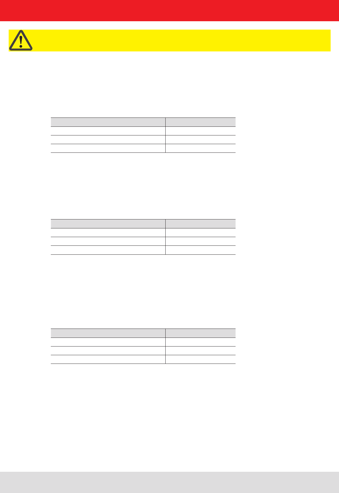
72
Important!
Since there are frequencies which the hardware of the RFID reader cannot deliver, when using the “Special”
communications standard, a spectrum analysis must be performed to check whether each channel frequency is
available for the correct setting.
7. Reader configuration
7.2.8.1. “CenterFreqCH0”
Characteristics:
available from fi rmware: v1.32.00
Data type: DWord (32-bit)
Unit: kiloHertz
Value range: 0-1048575
Description:
This confi guration parameter specifi es the mid-frequency of channel 0 for the “Specia” communications standard.
7.2.8.2. “ChannelWidth”
Characteristics:
available from fi rmware: v1.32.00
Data type: Word (16-bit)
Unit: kiloHertz
Value range: 0-65535
Description:
This confi guration parameter allows the width of each radio channel for the “Special” communications standard
to be specifi ed.
7.2.8.3. “MaxChannelTime”
Characteristics:
available from fi rmware: v1.32.00
Data type: Word (16-bit)
Unit: milliseconds
Value range: 0; 10-65535
Description:
This confi guration parameter for the “Special” communications standard specifi es how long the reader may occupy a
selected channel until it must change to the next channel.

73
7. Reader configuration
7.2.8.4. “MinChannelWaitTime”
Characteristics:
available from fi rmware: v1.32.00
Data type: Word (16-bit)
Unit: milliseconds
Value range: 0-65535
Description:
This confi guration parameter for the “Special” communications standard specifi es how long the reader must wait
before returning to a channel after its maximum exposure time (“MaxChannelTime”) has elapsed.
7.2.8.5. “FirstChannel”
Characteristics:
available from fi rmware: v1.32.00
Data type: Byte (8-bit)
Unit: –
Value range: 0-255
Description:
This confi guration parameter for the “Special” communications standard specifi es the fi rst channel to be used for this
communications standard. The frequency of the channel is determined by the following formula:
7.2.8.6. “LastChannel”
Characteristics:
available from fi rmware: v1.32.00
Data type: Byte (8-bit)
Unit: –
Value range: 0-255
Description:
This confi guration parameter for the “Special” communications standard specifi es the last channel to be used for this
communications standard. The frequency of the channel is determined by the following formula:
f = “CenterFreqCH0” + “FirstChannel” * “ChannelWidth”
f = “CenterFreqCH0” + “LastChannel” * “ChannelWidth”

74
8. Reference literature
(A) Kathrein-Burgstädt Reader Protocol (KBRP) V1.23
(B) EPCTM Radio-Frequency Identity Protocols Class-1 Generation-2 UHF RFID in the version V1.2.0 on
www.epcglobalinc.org

0711/ZWT - Technical data subject to change.
Internet: www.kathrein-rfi d.de
KATHREIN-Werke KG • Anton-Kathrein-Straße 1 - 3 • P.O. Box 100 444 • 83004 Rosenheim • GERMANY • phone +49 8031 184-0 • Fax +49 8031 184-494