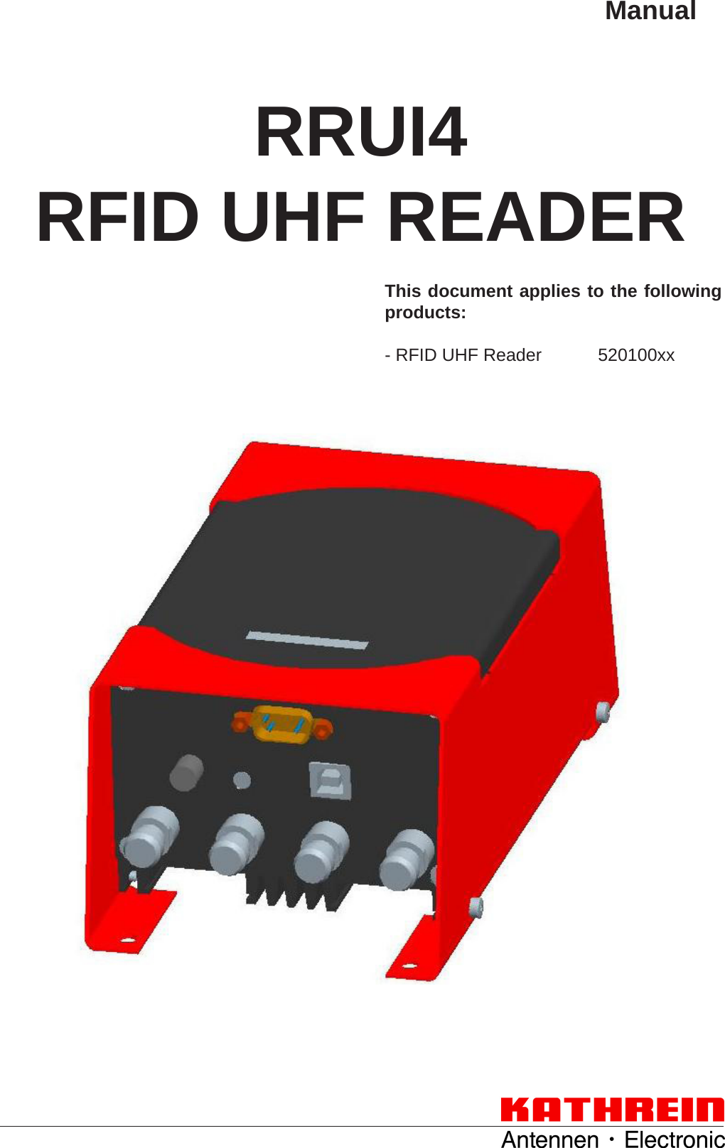
KATHREIN Sachsen RRUI4RS4U4 RFID UHF Reader User Manual 9363456a Manual RRUI4 RFID UHF Reader
KATHREIN Sachsen GmbH RFID UHF Reader 9363456a Manual RRUI4 RFID UHF Reader
UserManual.wiki
>
KATHREIN Sachsen
>
RRUI4RS4U4 User Manual
User Manual
Navigation menu
Upload a User Manual
Namespaces
Wiki Guide
HTML
PDF
Info
Views
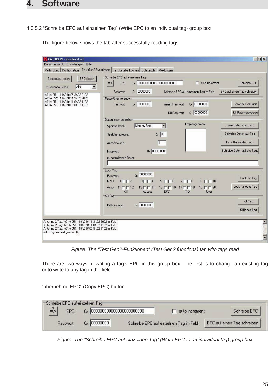
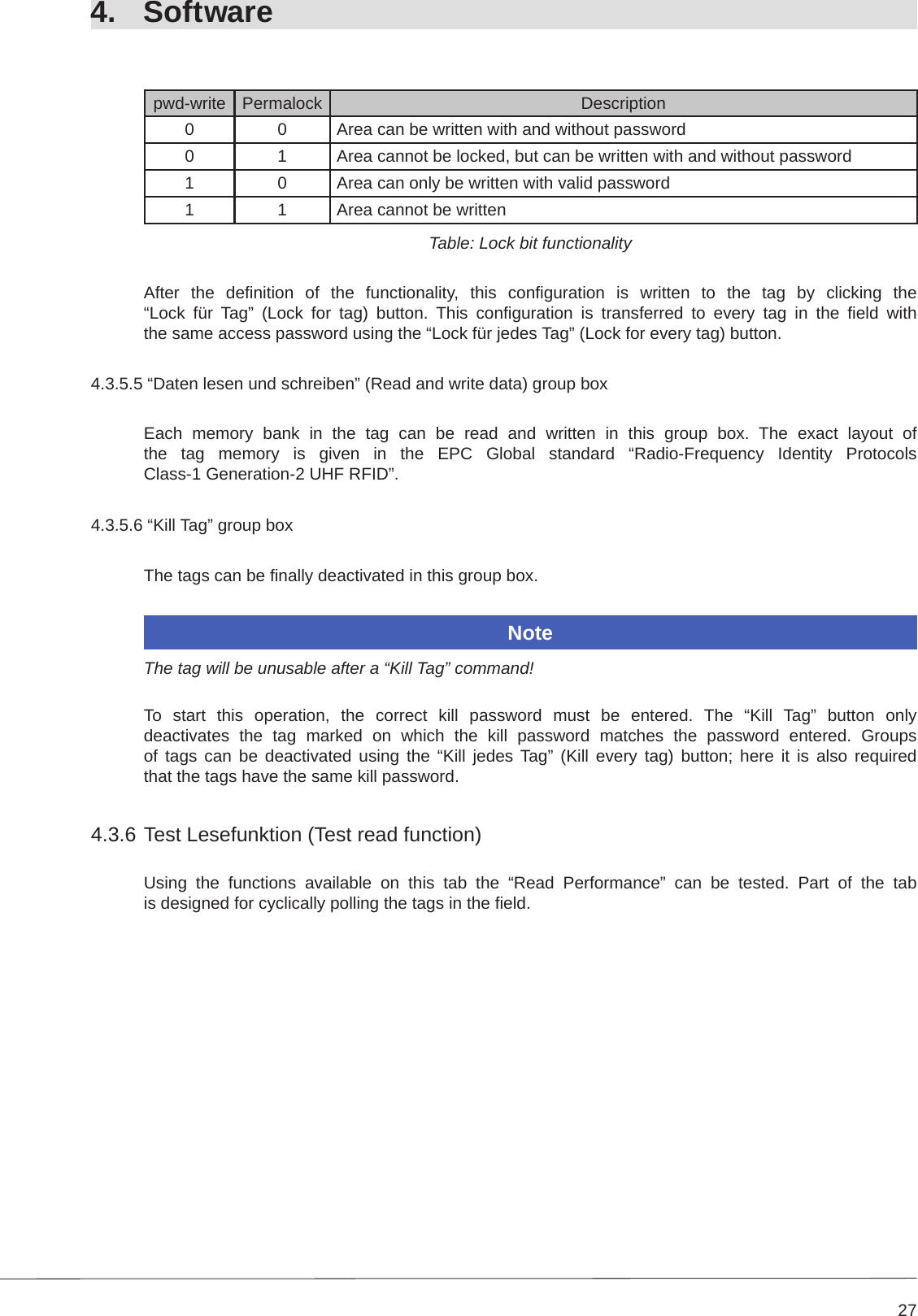
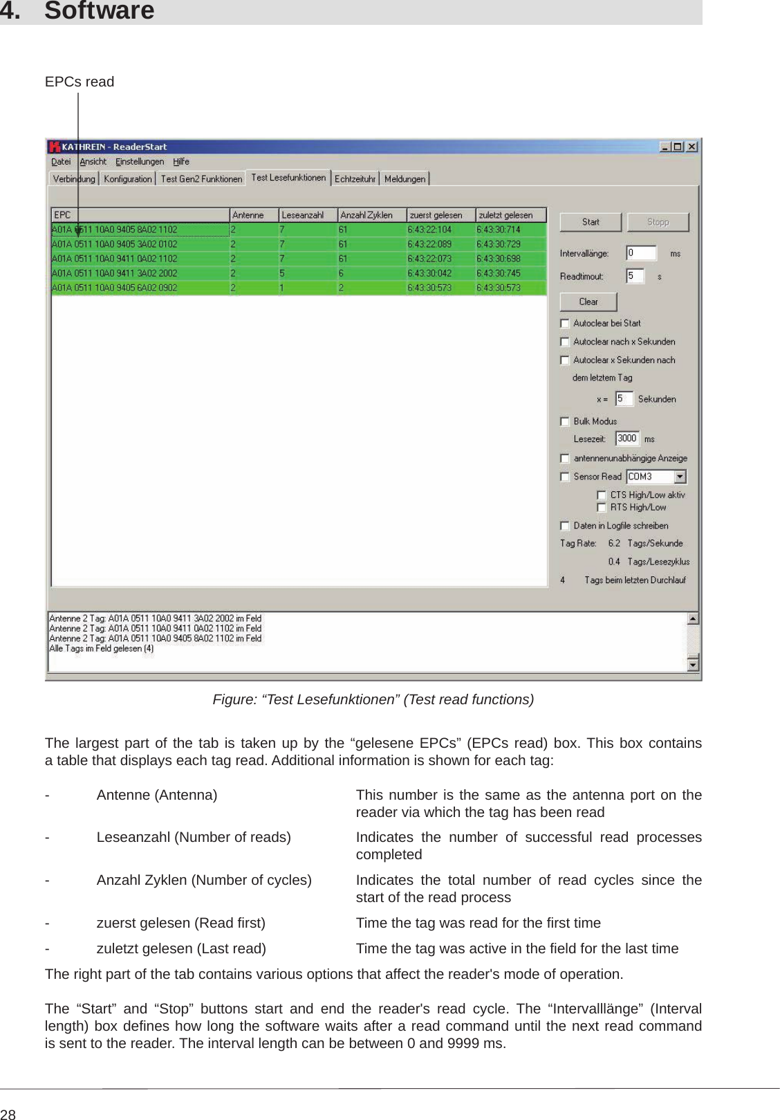
User Manual
Discussion / Help
Navigation