KATHREIN Sachsen RRUI4RS4U4 RFID UHF Reader User Manual 9363456a Manual RRUI4 RFID UHF Reader
KATHREIN Sachsen GmbH RFID UHF Reader 9363456a Manual RRUI4 RFID UHF Reader
User Manual
Manual
RRUI4
RFID UHF READER
This document applies to the following
products:
- RFID UHF Reader 520100xx

2
Foreword and General Information
This document or extracts of this document is/are not allowed to be copied or distributed in any form or by
any means (electronic or mechanical) for any purpose without the prior written approval of Kathrein.
Kathrein does not accept any liability for omissions or inaccuracies in this document or in relation to the
provision or usage of the information contained in this document. Kathrein reserves the right to change
the products described in this document and does not accept any liability in relation to the application or
usage of one of the products described in this manual.
This document and the information it contains are proprietary information belonging to Kathrein and
confi dential. Kathrein provides this document to its customers in the context of purchase contracts for the
products described in it. If the holder of this document as a legal entity or person is not party to a purchase
contract concluded with Kathrein, or Kathrein does not otherwise envisage him/her as the recipient of
this document and the information it contains, the holder is herewith informed that its usage is unlawful
and an infringement of Kathrein's rights.
Copyright note
The information in this manual was correct at the time of going to press.
We reserve the right, however, to make changes at any time and without prior notice.
This document was prepared for specialist personnel who install, confi gure and place in operation the reader.
Scope
The information in this manual is intended to support the development process and development
guidelines at the customer. In addition, this manual provides supporting information on the applicable
standards for the related installation location, as well as the relevant safety standards related to the
installation and confi guration of the Kathrein reader.
General information
This manual includes information on the installation, confi guration, operation and maintenance of the
reader. In addition, detailed technical data is provided with the intention of better informing users about the
reader's features.
Therefore, in the interests of long service life and trouble-free operation, read this manual carefully and
follow all the instructions and information it contains.
Warranty
Switching on the AC or DC power supply prior to connecting the antenna cable is considered incorrect
installation. Any malfunctions that then occur subsequently are therefore also not covered by the warranty.
The manual should be read and understood in its entirety prior to setup or maintenance of the reader. We
accept no liability if the customer fails to take the precautionary measures given here. The warranty is void in
such cases.
Disposal Instructions
Electronic equipment is not domestic waste - in accordance with directive 2002/96/EC OF
THE EUROPEAN PARLIAMENT AND THE COUNCIL dated 27th January 2003 on used
electrical and electronic appliances, it must be disposed of properly.
At the end of its service life, take this unit for disposal to an appropriate offi cial collection
point.
Spent batteries are special waste.
Do not throw spent batteries into your domestic waste; take them to a collection point for used
batteries.

3
Contents
Foreword and general information 2
Copyright note 2
Scope 2
General information 2
Warranty 2
Disposal Instructions 2
Contents 3
1. Safety instructions/information 4
General safety instructions 4
Mains voltage 4
Ventilation 5
Damp, sunlight, heat, naked flames 5
Radiated electromagnetic fields 5
Battery 5
CE and FCC marking 5
2. Introduction 7
2.1 The reader 7
2.2 Product package 7
2.3 Accessories 7
2.4 Installation location 7
2.5 Connections/Displays 8
2.6 Data sheet 10
3. Installation 12
3.1 Hole pattern (mm) 12
3.2 Selecting the installation site 12
3.3 Installing the reader 12
4. Software 13
4.1 System requirements 13
4.2 Installation 13
4.3 Operation 15
5. Contact addresses 32
4
1. Safety Instructions/Information
Figure legend
Caution Indicates a potentially dangerous situation that can result in minor to
serious injuries and/or damage to the unit on failure to observe.
Note Provides information that makes it easier to understand a specifi c topic
and/or to be able to optimally utilise the functionality of the unit.
Caution!
Before you start to install or replace the unit, the manual provided must be read
carefully and understood.
The details given in our data sheets and in this manual must be carefully followed
and observed during the installation of the reader and during operation!
The installation team must hold suitable qualifi cations and be familiar with the
relevant national safety regulations.
Connection, setup, maintenance and other work on the unit are only allowed to be
undertaken by suitably qualifi ed staff with appropriate training.
The unit is only allowed to be used for the purpose intended by the manufacturer.
Unauthorised modifi cations and the usage of spare parts and additional units
that are not sold or recommended by the manufacturer can cause fi res, electric
shock and injuries. Such actions will therefore result in exclusion of liability and the
manufacturer will not provide any warranty.
The version of manufacturer's warranty conditions applicable at the time of purchase
apply to the unit. No liability is accepted for unsuitable manual or automatic
adjustment of the unit's parameters or the unsuitable usage of the unit.
Repairs are only allowed to be undertaken by authorised personnel. Opening the
unit and attempting to repair it yourself will void all warranty claims! Improper work
on the unit may jeopardise the electrical safety of the unit.
The manufacturer accepts no liability for accidents caused by the user opening
the unit!
The related applicable safety regulations must be followed when working on the unit.
Mains voltage
Make sure that the mains cable (power supply cable) is not damaged. Units with a
damaged mains cable must be disconnected from the mains (disconnect mains
connector) and repaired by a qualifi ed engineer before setup. Only use the power
supply unit provided!
Mortal danger due to electric shock!
Only operate the unit at the specifi ed mains voltage (indicated on the rear of the
unit or on the external power supply unit)!
If the mains voltage is too high, there is a risk of fi re!
Caution
General safety instructions
5
1. Safety Instructions/Information
Damp, sunlight, heat, naked fl ames
The unit should be protected from damp, dripping water and splashing. Do not place
the unit close to a heater or expose it to direct sunlight and do not operate it in damp
locations. Only use the unit in a moderate climate, not in tropical conditions! Do not place
any naked fl ames on the unit! 1)
There is a risk of fi re!
Ventilation
The heat generated in this unit is adequately dissipated. However, the unit should
never be installed in a cupboard or on shelves with inadequate ventilation.
Never cover over the unit's ventilation slots.
There is a risk of fi re!
Caution!
Caution!
Radiated electromagnetic fi elds
This reader is designed for operation as per EN 302208. On the operation of the unit with
antennas connected, the human exposure regulations in accordance with EN 50364
are to be observed. Ensure there is a minimum distance of 23 cm between antenna
and human bodies. In some circumstances, heart pacemakers may suffer interference
if wearers are close to the antenna when the unit is in operation (reader and antenna).
In case of doubt, the people affected are requested to contact the manufacturer of their
pacemaker or their doctor.
The reader output power is to be reduced as a function of the antenna cable length and
the antenna gain.
Caution!
Battery
The battery incorporated in the device may be replaced only by a battery of the same
type. It must be installed by a trained fi tter. If the battery is replaced by one of the wrong
type or is wrongly connected.
There is the risk of an explosion.
Attention!
1) If the unit is not expressly designed for these installation locations/conditions.
CE and FCC marking
The unit complies with the applicable CE requirements and FCC part 15.
Brand Name: Kathrein RRUI4 RFID-UHF-Reader
Model Name: 52010025 - 52010034
FCC ID: __________________
This device complies with part 15 of the FCC Rules. Operation is subject to the following
two conditions: (1) This device may not cause harmful interference, and, (2) This device
must accept any interference received including interference that may cause undesired
operation.

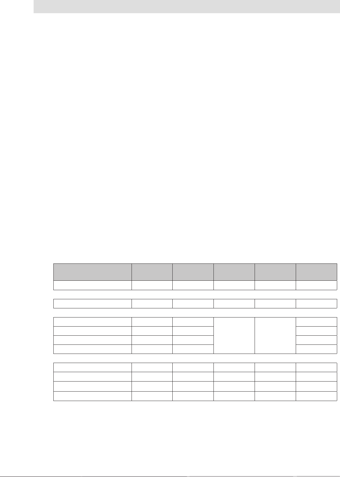
6
Kathrein FCC-ID ICC-ID
XXX XXXXXX - YYYYYYYY
Type details Part no. Grantee code ID code Company number Unique Product Number
applied for 14 digits free applied for 8 digits free
RRUI4-RS4-U4 52010025 WJ9 - RRUI4RS4U4 5530C - RRUI4RS4
RRUI4-USB-U4 52010026 WJ9 - RRUI4USBU4 5530C - RRUI4UB4
RRUI4-ETH-U4 52010027 WJ9 - RRUI4ETHU4 5530C - RRUI4EH4
RRUI4-ETG-U4 52010028 WJ9 - RRUI4ETGU4 5530C - RRUI4EG4
RRUI4-RS4-U5 52010029 WJ9 - RRUI4RS4U5 5530C - RRUI4RS5
RRUI4-ETH-U5 52010030 WJ9 - RRUI4ETHU5 5530C - RRUI4EH5
RRUI4-ETG-U5 52010031 WJ9 - RRUI4ETGU5 5530C - RRUI4EG5
RRUI4-RS4-U6 52010032 WJ9 - RRUI4RS4U6 5530C - RRUI4RS6
RRUI4-ETH-U6 52010033 WJ9 - RRUI4ETHU6 5530C - RRUI4EH6
RRUI4-ETG-U6 52010034 WJ9 - RRUI4ETGU6 5530C - RRUI4EG6
Note
Changes or modifi cations made to this equipment not expressly approved by
Kathrein may void the FCC authorization to operate this equipment.
This equipment has been tested and found to comply with the limits for a Class B digital
device, pursuant to Part 15 of the FCC Rules. These limits are designed to provide
reasonable protection against harmful interference in a residential installation. This
equipment generates, uses and can radiate radio frequency energy and, if not installed
and used in accordance with the instructions, may cause harmful interference to radio
communications.
However, there is no guarantee that interference will not occur in a particular
installation.
If this equipment does cause harmful interference to radio or television reception, which
can be determined by turning the equipment off and on, the user is encouraged to try to
correct the interference by taking one or more of the following measures:
-- Reorient or relocate the receiving antenna.
-- Increase the distance between the equipment and receiver.
-- Connect the equipment into an outlet on a circuit different from that to which the
receiver is connected.
-- Consult the dealer or an experienced radio/TV technician for help.
RF Exposure Warning
This equipment complies with FCC radiation exposure limits set forth for an uncontrolled
environment. This equipment should be installed and operated with a minimum distance
of 20 cm between the radiator and your body.
Professional Installation Notice:
To comply with FCC part 15 rules in the United States, the system must be professionally
installed to ensure compliance with the part 15 certifi cation. It is the responsibility of the
operator and professional installer to ensure that only certifi ed systems are deployed in
the United States. The use of the system in any other combination (such as co-located
antennas transmitting the same information) is expressly forbidden.
1. Safety Instructions/Information
7
2. Introduction
2.1 The reader
The Kathrein RFID (Radio Frequency Identifi cation) Reader RRUI4 is a multiprotocol reader for
reading active and passive tags in the frequency range from 865 MHz to 868 MHz for Europe or
902 MHz to 928 MHz for FCC. The unit operates, depending on the approval region, with 2 W RF
output power or 1 W RF power at the antenna socket. As supplied the unit can read and write tags in
accordance with the EPC-Gen2 standard. Additional protocols can be loaded using software updates.
The unit has various interfaces for communication.
The reader has four antenna connections for connecting transmitting/receiving antennas for
communication with RFID tags. The unit has various interfaces for the connection to the PC, depending
on the confi guration and degree of protection. Depending on the variant, the unit can be supplied
with power via the RS 485/ RS 422 interface or via a 3-pin M8 connector.
2.2 Product package
1 RRUI4 (colour scheme: black housing with red cover)
1 CD with demo software and operating instructions
1 Plug-in power supply unit 24 V/45 W
1 Mains cable (not heat resistant)
1 USB cable (A to B)
1 Data sheet
2.3 Accessories
Antennas: → Can be used with UHF RFID antennas; Kathrein antenna types are recommended
e. g. 52010003, 52010004 and 52010060
Antenna cable:
Designation Order no. 50-Ω
cable type Connector
1Connector
2Length (cm)
Cable 3 m, SMA-N 52010049 RG058-PE SMA (m) N (m) 300
Cable 3 m, SMA-SMA 52010050 RG058-PE SMA (m) SMA (m) 300
Cable 1 m, TNC-TNC(rev) 52010051 RG058-PE
TNC(f)-rev TNC(m)
100
Cable 2 m, TNC-TNC(rev) 52010052 RG058-PE 200
Cable 3 m, TNC-TNC(rev) 52010053 RG058-PE 300
Cable 6 m, TNC-TNC(rev) 52010054 RG058-PE 600
Cable 1 m, N-TNC(rev) 52010055 RG058-PE TNC(f)-rev N (m) 100
Cable 2 m, N-TNC(rev) 52010056 RG058-PE 200
Cable 3 m, N-TNC(rev) 52010057 RG058-PE 300
Cable 6 m, N-TNC(rev) 52010058 RG058-PE 600
Table: Original Kathrein antenna cables
2.4 Installation location
The standard version of the unit complies with the degree of protection IP 40. Variants with a higher
protection class are available on request and comply with the related IP requirements specifi ed.
8
2. Introduction
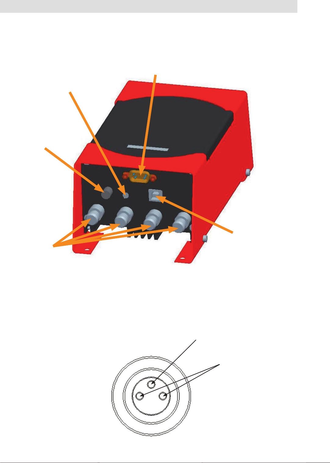
The fi gure below shows the front of the reader with all available connections on the IP 40 variant.
2.5 Connections/Displays
Antennas
connectors
USB port
Power
connector
LED
RS 485/RS 422 interface
2.5.1 Supply of power
The power is supplied via a 3-pin M8 connector or via the 9-pin Sub-D socket. The pin assignments
on the housing connector are shown in the illustration below:
Positive pole
Earth
Figure: Front end of the RRUI 4

9
2. Introduction
2.5.3 Connection via USB (only IP 40 units)
For confi guration purposes the reader is equipped with a USB socket of type B. The DLL fi le on the CD
supplied requires to operate the unit using this port.
2.5.4 Antenna connection
For connecting the RFID antennas the reader has four antenna connectors designed in “reverse TNC”.
Please only use the cables from the accessories (see 2.3) or equivalent cables for this connection.
Note
Please only use cable suitable for the impedance (50 Ohm), as otherwise the performance of
the reader will be severely limited by the mismatch. If the mismatch is large, the reader may
indicate a fault (“Antenna faults”).
2.5.5 LED
The reader has a 2-colour LED for the indication of the operating state. The table below shows the
colours used and the related operating state.
Red Green Operating state
X Flashes approx. every 8 seconds Error during initialisation
X X Unit is booting
Flashes approx. every 8 seconds X Normal operation with heartbeat
Table: Indication of the operating states by the LED
2.5.6 Buzzer
The reader also has a buzzer that, in addition to the LED, indicates successful booting (1 x short)
or an error (2 x long).
2.5.2 RS 422/RS 485
The reader's interface card is equipped with a
combined RS 485/RS 422 interface. The interface
is switched between RS 485 and RS 422 with
the supplied confi guration tool (see 4.3.4.2).
The unit can also be supplied with power via
this interface. The table on the right shows the
pin assignments for the 9-pin Sub-D socket,
as well as the M12 connector:
PIN Sub-D 9-pin M12
RS 485 - A 3 5
RS 422 - A - TX 4 4
RS 485 - B 8 6
RS 422 - B - TX 9 2
GND screen Screen 8
+ 24 V Ub 7 1
Ground Ub 2 3
Table: Connector pin assignment, Sub-D
socket
For operation with RS 422, the RS 485 wires are
switched to RX.
10
2. Introduction
2.6 Data sheet
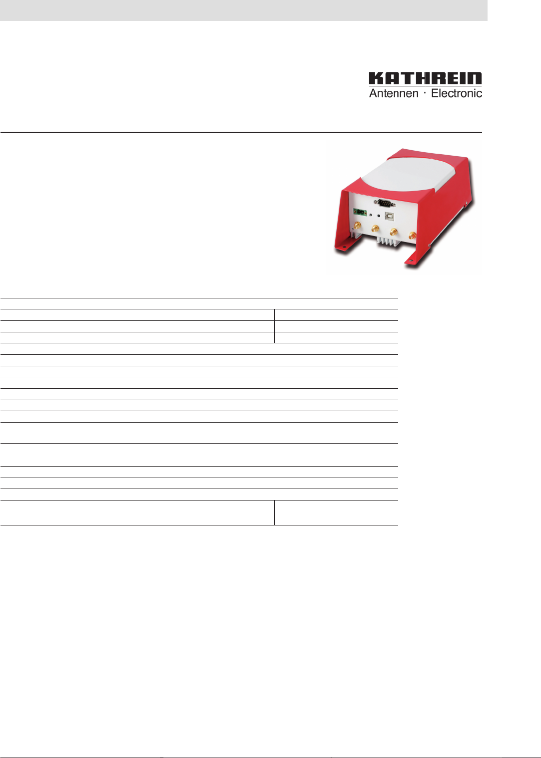
RRUI 4 RFID UHF Reader System
4-Way Antenna Interface
Order no. 520 100xx
936.3276b Subject to change
The Kathrein RRUI 4 Series is a new GEN2 modularly designed reader sys-
tem which allows the user to select a wide range of different function blocks to
obtain an optimised solution for today’s RFID challenges.
The RRUI 4 Series is targeted to the next generation of RFID UHF applica-
tions to solve problems in the supply chain and in the manufacturing area. Key
segments are the Automotive Industry, Automation Systems, Telecommunica-
tions and Logistics.
The RRUI 4 Series is based on the Impinj Indy R1000 UHF chipset to provide
highest performance with essential reduction of system costs.
General Specifi cations: ECE Version US Version
Frequency range 865-868 MHz 902-928 MHz
Output power + 30 dBm + 30 dBm conducted (FCC)
Emitted power (max.) + 33 dBm ERP -
Protocols EPC Class1 GEN2/ISO 18000-6C
Nominal impedance (antenna ports) 50 ohms
LBT Sensitivity -96 dBm
Antenna interface 4 Port TX/RX interface with TNC-reverse (male) connectors
Communication interface see Reader overview
Operating system Kathrein Firmware @ ARM 9 Proc.
Power supply + 24 V DC ±10%
Operating temperature range -20°C to +55°C
Storage temperature range -20°C to +85°C
Dimensions 200 x 108 x 81 mm
Weight 1.32 kg
Environmental Protection see RFID UHF Reader overview
Conform to: EN 302 208-1, EN 301 489-3,
CE, ETSI, FCC
Technical Features:
• System compliant to EPCglobal Gen2/ISO 18000-6C standards
• Software-defi ned radio architecture based on Impinj Indy R1000
• Combined TX/RX antenna ports
• Support LBT Listen before talk (ETSI EN 302 208-1)
• Dense Reader Mode (DRM)
• Modulation modes: DSB, PR-ASK
• Output power range justable from 20 dBm upto 33 dBm (100 mW up to 2 W)
• Ready for Kathrein RFID Antenna Interface KRAI ©
Delivery scope:
• Reader System RRUI4-xxx-xx
• Network adapter + 24 V DC (only covers IP 40)
• Types with USB port: USB connecting cable A → B
• CD-ROM with manual and data sheet (pdf)
11
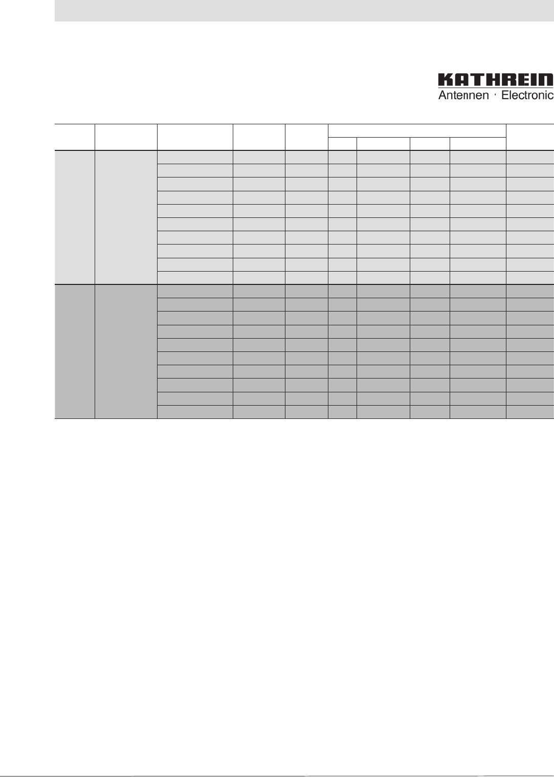
2. Introduction
Region
(Norm) Device Type Order No. Housing Connectors Protection
class
USB RS 422/485 Ethernet Eth. M. GPIO
EU
(CE)
Kathrein-
RRUI4
(4-way multiplex)
RRUI4-RS4-E4 52010009 sw/rt X X IP 40
RRUI4-USB-E4 52010016 sw/rt X IP 40
RRUI4-ETH-E4 52010017 sw/rt X X IP 40
RRUI4-ETG-E4 52010018 sw/rt X X IP 40
RRUI4-RS4-E5 52010019 sw/rt X IP 54
RRUI4-ETH-E5 52010020 sw/rt X IP 54
RRUI4-ETG-E5 52010021 sw/rt X IP 54
RRUI4-RS4-E6 52010022 sw/rt X IP 65
RRUI4-ETH-E6 52010023 sw/rt X IP 65
RRUI4-ETG-E6 52010024 sw/rt X IP 65
US (FCC) Kathrein-
RRUI4
(4-way multiplex)
RRUI4-RS4-U4 52010025 sw/rt X X IP 40
RRUI4-USB-U4 52010026 sw/rt X IP 40
RRUI4-ETH-U4 52010027 sw/rt X X IP 40
RRUI4-ETG-U4 52010028 sw/rt X X IP 40
RRUI4-RS4-U5 52010029 sw/rt X IP 54
RRUI4-ETH-U5 52010030 sw/rt X IP 54
RRUI4-ETG-U5 52010031 sw/rt X IP 54
RRUI4-RS4-U6 52010032 sw/rt X IP 65
RRUI4-ETH-U6 52010033 sw/rt X IP 65
RRUI4-ETG-U6 52010034 sw/rt X IP 65
12
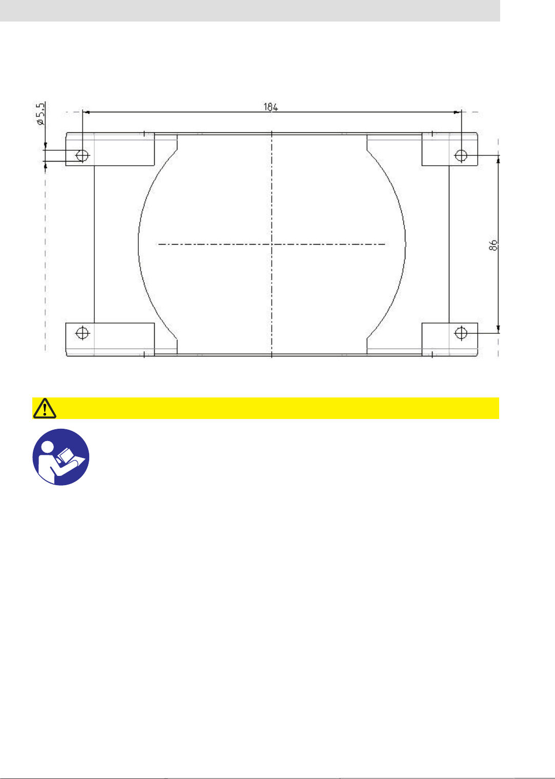
3. Installation
The reader has four holes of 5.5 mm diameter in its cover for fastening.
Figure: Underside of RRUI 4 with fastening holes
3.2 Selecting the installation site
Pay attention to the unit's degree of protection when selecting the installation site. The standard
version (IP 40) of the reader is only designed for usage indoors. The installation site must be
protected against water splashes in this case. Space is to be provided around the unit so that the
heat produced in the unit can dissipate adequately.
3.1 Hole pattern (mm)
Prior to installing, read the safety instructions at the start of this manual!
Caution!
- The reader (the unit) is only to be fastened using the holes on the cover
- Attention is to be paid to the mounting surface when selecting the fastening material
- Strain relief should be used on the cables to protect the connections
3.3 Installing the reader
13
4. Software
For test purposes the reader can be operated using the demo software on the CD supplied.
This software includes all the reader's functionality. For integration in enterprise resource planning
systems, there is a DLL fi le on the CD for programming custom routines.
4.1 System requirements
To ensure correct operation using the software on your PC/laptop, your PC/laptop should meet
the following minimum requirements:
Processor: X 86 compatible
Memory: 512 MB RAM
Operating system: Windows XP
Spare hard disk space: 3 MB
4.2 Installation
The demo software is installed by running “KathreinRFIDDemoSetup.exe” on the CD-ROM
supplied. During this process the demo software and the DLL for controlling the reader are installed.
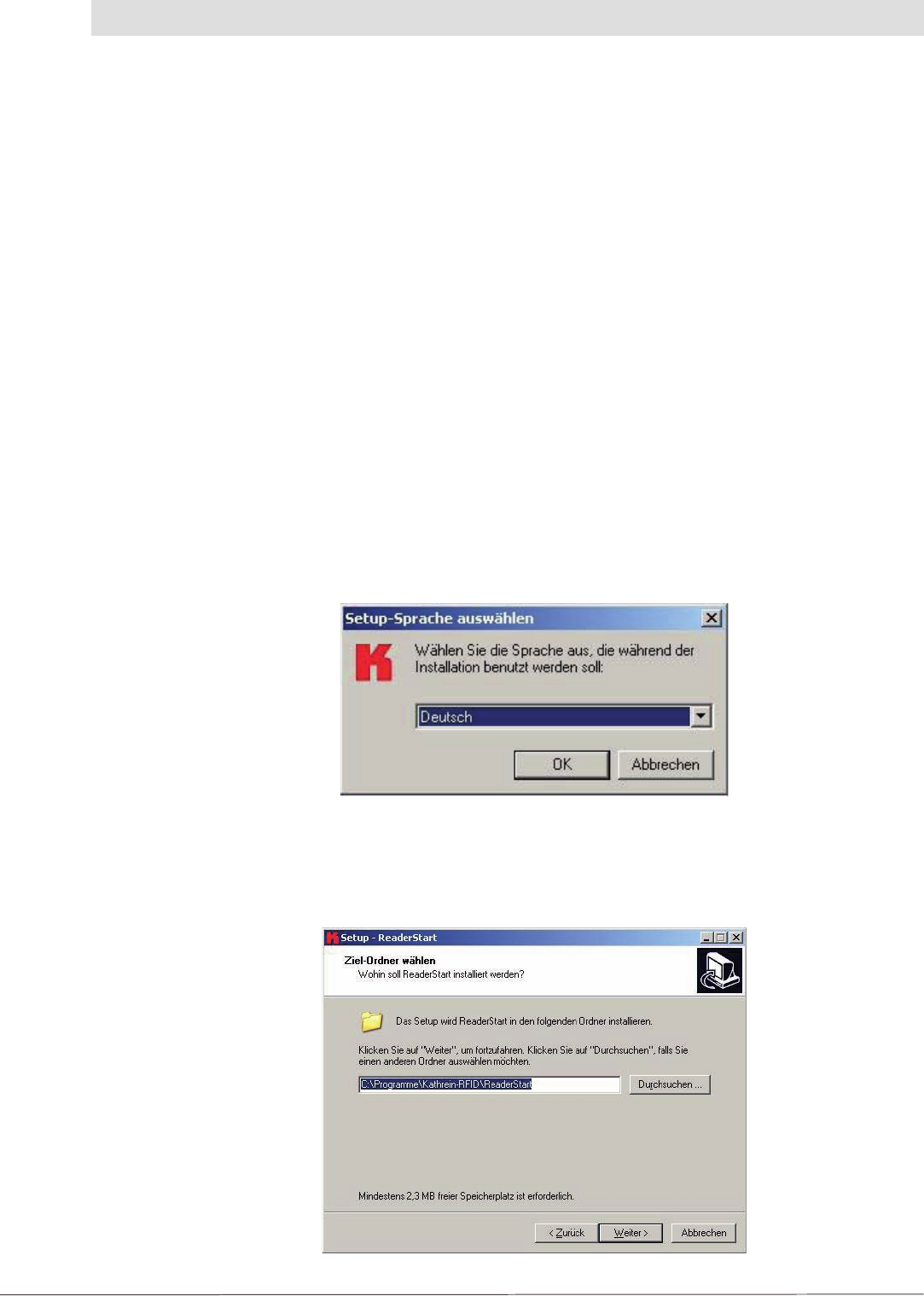
You can change the language used during the installation in the dialog box that now opens.
Accept your selection by clicking the “OK” button.
Figure: Installation, language selection
Now follow the instructions in the dialog box. Select an installation folder and a name for the folder
on the Start menu, if you want to change the defaults.
Figure: Installation, selecting installation folder
14
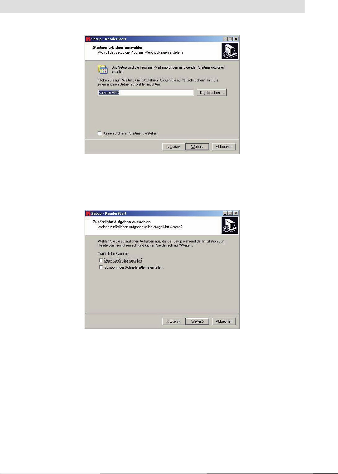
Figure: Installation, select Start menu folder
In the next dialog box, defi ne whether the setup is to create a desktop icon and an icon on the
quick start toolbar.
Figure: Installation, Zusätzliche Aufgaben
auswählen (Select additional tasks)
4. Software
15
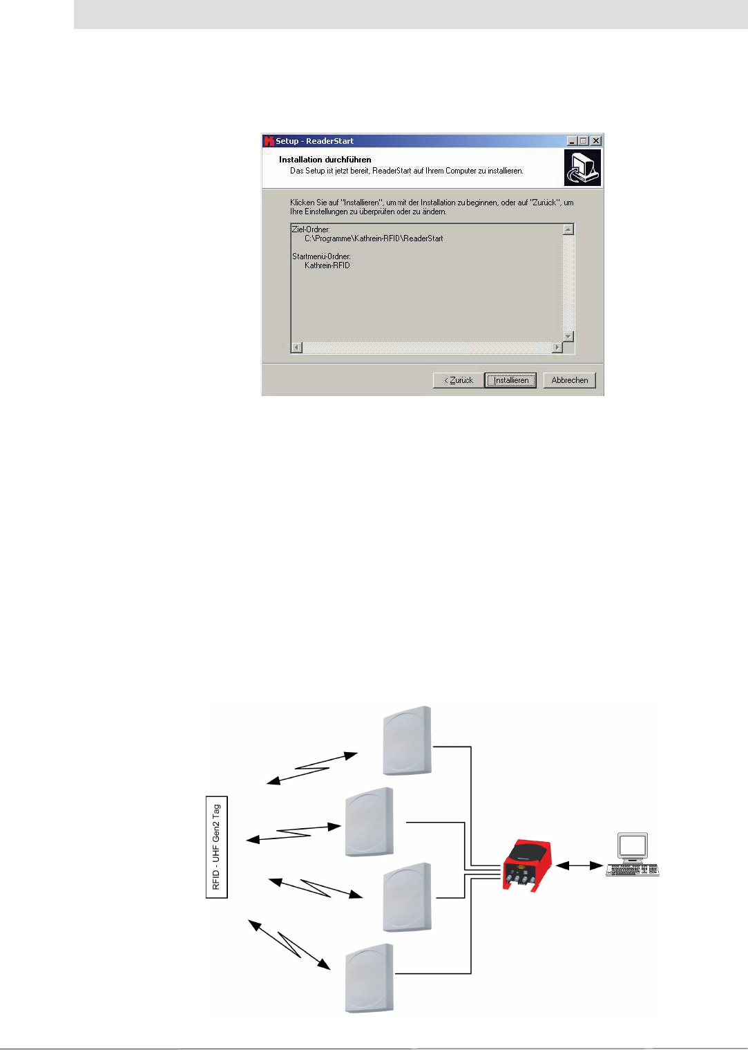
Figure: Installation, summary of the installation tasks
“Installation durchführen” (Install)
A summary of the installation tasks is then displayed. Start the installation process by clicking the
“Installieren” (Install) button.
4.3 Operation
The test software “ReaderStart” for the RRUI4 is described in the section that follows. Before the
description addresses the user interface and the individual confi guration features and controls,
the principle of operation of this RFID reader system is described.
4.3.1 General
An RFID system comprises, along with a control computer and the actual reader, also the
antennas for the reader, the antenna connection cables and the tags. The fi gure below shows the
schematic layout of the system:
Figure: Schematic illustration of an RFID reader system
4. Software
16
The computer controls the reader via one of the available interfaces and receives over this interface
the EPCs and data from the tags read.
To read from an EPC tag, the reader emits an RF carrier via the active antenna and in this way
supplies the tag with power. If the information on the tag is now to be read, a connection to the tag
is established. For this purpose the tag is selected from a possible number of tags (singularisation).
For the transmission of data from and to the tag, the reader requests a handle from the tag. The rest
of the communication with the tag can be undertaken using this handle and the EPC read.
The tag's EPC is transferred from the reader to the PC and displayed on the PC with additional
information. This information includes, along with the time the tag was read, also the antenna used for
communication with the tag. It is always possible to communicate directly with the tag using this EPC,
as soon as the tag is in range of the reader.
The ReaderStart application communicates with the reader using the DLL supplied. On the
user interface it provides information on all the unit's functions of relevance to the user. Every
connection between the application and the reader over the various interfaces in the reader is made
using this DLL. The functions that can be used are listed in the header fi le “ReaderDll.h”.
4. Software
4.3.2 User interface description
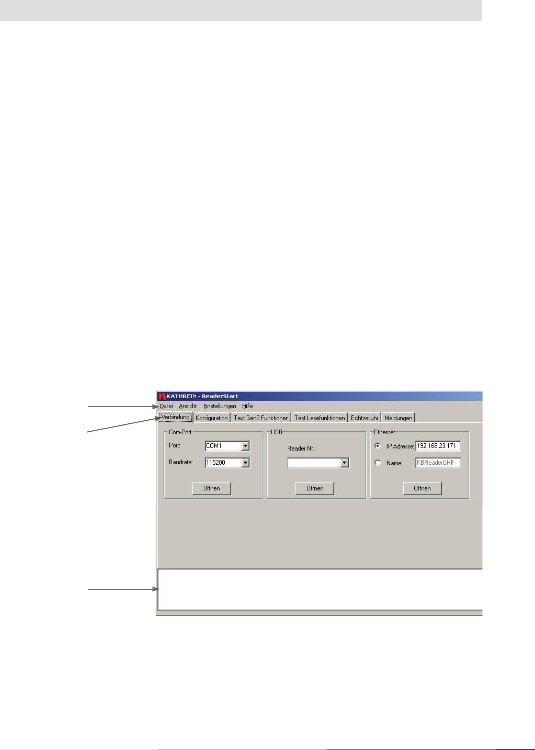
The program is started by double-clicking “ReaderStart.exe”. After a splash screen, the program's
user interface appears.
Figure: ReaderStart user interface
Menu bar
Tab
Status box
The status box contains current messages from the reader and can be seen on every tab.

17
4.3.3 Establishing connection
The “Verbindung” (Connection) tab contains all controls for establishing a connection to the reader.
Depending on the unit, it is possible to establish a connection via RS 485 or RS 422, via USB or via
Ethernet.
4. Software
4.3.3.1 “ComPort” group box
The serial interface is used for the communication with the reader via RS 485 or RS 422. The
RS 485/RS 422 interface card supports the standard data rates of the serial interface on a PC. A level
converter is also required for the communication to convert the RS 232-compliant signal from the
PC into a differential RS 485/RS 422 signal.
A serial com port on the PC can be opened in this group box. For this purpose the correct
serial interface must be selected in the “Port” drop-down list box. Only the ports available on
the PC are displayed in this list box. It is not checked whether this port is already in use by other
applications.
The required baud rate must also be set in the list box below. The com port is opened by clicking
the “Öffnen” (Open) button and the port is then no longer available for other applications. If
this port is already in use by another application, a corresponding error message is displayed.
If the port is free, the reader can be operated using this port.
4.3.3.2 “USB” group box
If an RRUI4 is connected to the PC via USB, the unit is installed in the system as a USB HID-
compliant device. Correct installation can be seen in the application if a number appears in the drop-
down list box after reader installation. This number is unique for each reader. If several readers are
connected to the PC, the related reader can be selected on this menu. The connection between
the reader and PC is now established by clicking “Öffnen” (Open).
4.3.3.3 “Ethernet” group box
The application offers two ways of establishing a connection to the reader via Ethernet (only
possible on readers with Ethernet interface). On the one hand, it is possible to communicate
directly with the reader by entering the IP address, on the other hand it is also possible to
establish a connection using the reader's host name.
To integrate the reader into a corporate network, please contact your administrator who will be
able to allocate you a spare IP address. If you want to connect the reader directly to the PC,
please use a cross-link cable (crossed network cable). You can use a standard patch cable for
connecting to the PC using a hub or switch.
If you have a spare IP address, you must allocate this address to the reader. For this purpose a
connection must be established to the reader (e. g. via USB). It is now possible to enter the IP address
on the “Konfi guration” (Confi guration) tab. After the confi guration has been saved it is possible to
communicate with the reader using this address. For this purpose, mark the “IP-Adresse” (IP address)
box and enter this address. The connection is established by clicking the “Öffnen” (Open) button.
For the connection using a DNS name, there must be a correspondingly confi gured DHCP and
DNS server in the network. If the reader is registered on the DHCP server and the DNS server, it is
also possible to connect to the reader using a network name. For this purpose, select the “Name”
box and enter the name agreed for the reader. The connection to the RRUI4 is established by
clicking the “Öffnen” (Open) button.
18
4. Software
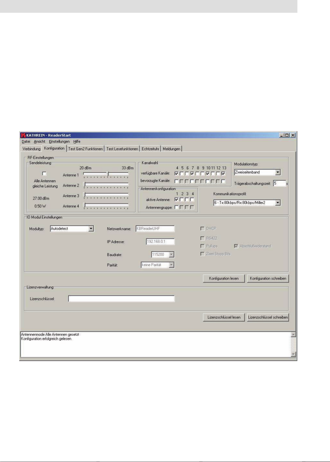
4.3.4 Konfi guration (Confi guration)
On the “Konfi guration” (Confi guration) tab it is possible to set all the RF parameters for the reader
as well as to set the parameters for the communication interfaces. It is also possible to read and
write the licence key for the reader on this tab.
If a connection has been established to the reader, the settings in the reader are read when
the “Konfi guration” (Confi guration) tab is opened. The confi guration can also be read manually
from the reader by clicking the “Konfi guration lesen” (Read confi guration) button. During this
process all settings in the user interface are overwritten. The current settings are saved in
the reader by clicking “Konfi guration schreiben” (Write confi guration). This action includes all
parameters in the “RF-Einstellungen” (RF settings) group box.
Figure: “Konfi guration” (Confi guration) tab

19
4.3.4.1 “HF-Einstellungen” (RF settings) group box
In this group box the radio frequency parameters, such as the transmission power, transmission
channel (EU only) and the spectrum can be set. The applicable standards in the related approval
region are to be observed when setting the transmission power.
4. Software
Note
To operate the reader in accordance with the related national standards, the antenna gain
and the cable attenuation must be taken into account in the transmission power setting. In no
circumstances is it allowed to exceed the permitted transmission power. Failure to observe this
instruction can result in non-compliant operation of the reader rendering void the unit's type approval.
Sendeleistung (Transmission power)
The RFID reader's transmission power can be set separately for each antenna or all antennas at
the same time. If the “Alle Antennen gleiche Leistung” (All antennas same power) check box is
selected, the sliders for the other antennas are set to the same power when a slider for the power
for antenna 1-4 is adjusted. If this check box is not selected, the power at the antennas can be set
separately for each output.
The radiated power is limited in Europe in accordance with ETSI 302208 to 2 W ERP. In the
FCC region, max. 1 W connected RF power applies with an antenna gain of 6 dBi. While the
European standard refers to a half-wave dipole, FCC part 15 refers to an isotropic radiator.
To set the transmission power, the length-dependent cable attenuation and the antenna gain
must be included in the calculation of the transmission power. An example for the calculation of the
transmission power for Europe and FCC is given in the following.
The following applies to the European approval region:
PReader = PERP + DCable - GAntenna
PReader ... Reader's transmission power in dBm
PERP ... Radiated power referred to a half-wave dipole in dBm
DCable ... Cable attenuation in dB
GHW ... Gain of the antenna referred to a half-wave dipole
The cable attenuation is the length-dependent attenuation of the cable at the related frequency:
DCable = L * Dper m
DCable ... Cable attenuation in dB
L ... Length in m
Dpro m ... Attenuation in dB/m
The antenna gain is stated in various different units. These units include dBi and dBic. The units
dBi and dBic refer to an isotropic (spherical) radiator, where dBic refers to a circularly polarised
isotropic radiator and dBi to a linearly polarised isotropic radiator.

20
4. Software
In the European approval area, the radiated power must not exceed 2 W ERP. This fi gure refers
to a half-wave dipole. The relationship shown below exists between an isotropic radiator (dBi)
and a half-wave dipole.
GHW = Gisot - 2.14 dB
GHW ... Gain referred to half-wave dipole
Gisot ... Gain referred to isotropic radiator in dBi
If the gain of the antenna is referred to the polarisation of a circular isotropic antenna (dBic), the
linear gain of the antenna is 3 dB lower. As a result the transmission power can be increased by 3 dB.
GHW = Gisot - 2.14 dB - 3 dB
GHW ... Gain referred to half-wave dipole
Gisot ... Gain referred to isotropic radiator in dBic
- In the FCC approval region, the RF power connected at the antenna input must not exceed 1 W
- If the gain of the antenna is higher than 6 dBi, the RF power connected must be reduced
correspondingly
- The reader's transmission power is then:
PReader = Pcond + DCable, with Pcond ≤ 1 W and Gisot ≤ 6 dB
PReader ... Reader's transmission power in dBm
DCable ... Cable attenuation
Gisot ... Gain of the antenna in dBi
Pcond ... Power at the antenna input in dBm
If the antenna gain is stated in dBic, the reader's transmission power can be increased by 3 dB.
The transmission power for the European variant can be set in 0.25 dB steps from 20 dBm to 33 dBm.
Kanalwahl (Channel selection)
The reader transmits, dependent on the approval region, in the frequency range 865 MHz to 868 MHz
for Europe or 902 MHz to 928 MHz for USA. In Europe the number of channels to be used can be
limited. For this purpose the related check box must be selected on the “verfügbare Kanäle” (Available
channels) list for each channel the reader is to use. In this manner it is possible to avoid from the start
the usage of specifi c channels on which there is interference. In the case of a read command, the
reader searches for a spare transmission channel using LBT (Listen Before Talk). The reader starts
to search through the channels in ascending order. As soon as it fi nds a free transmission channel,
the reader starts to send its data on this channel.

21
Antennenkonfi guration (Antenna confi guration)
If all antenna outputs on the reader are selected, the reader attempts to read the tags in the fi eld
starting at antenna 1. Once no more new tags are found, the reader switches to the next antenna. It is
then again attempted to read all tags that reply to the reader's request. This process starts again from
the beginning after the last antenna.
If not all antennas are selected, the reader starts its request with the lowest antenna selected and
then switches through all antennas selected in ascending order.
It is possible to quickly select the antennas to be used on the “Test Gen2-Funktionen” (Test Gen2
functions) tab by forming an antenna group. For this purpose a selection must be made from the
active antennas by selecting the check boxes in the “Antennengruppe” (Antenna group) list. The
resulting group can now be selected using the “Test Gen2-Funktionen” (Test Gen2 functions).
The “Tags lesen” (Read tags) function is then only performed for this group.
Modulationstypen (Modulation types)
The modulation type can be switched between “Zweiseitenband” (double sideband) and PR-ASK
modulation in this drop-down list box.
Trägerabschaltzeit (Carrier shut down time)
The “Trägerabschaltzeit” (carrier shut down time) defi nes how long an RF carrier remains enabled
after the last command from the reader to the tag. If the time between two commands is long, it is
recommended to shut down the carrier to save energy and to avoid using the channel unnecessarily.
The shut down time can be set as an integer from 0 to 65535 seconds.
Mögliche Kommunikationsprofi le (Possible communication profi les)
If the confi guration is read, the communication profi les that can be used are read from the reader
and can be selected in the drop-down list box. The profi le defi nes the speed at which data are
transmitted to and from the tag. The person confi guring the reader thus has direct control over the
performance of the reader and the spectral characteristics of the transmission signal.
4. Software
Table: List of communication profi les
Profi le number Profi le name
1 Tx:40kbps/Rx:80kbps/FM0
2 Tx:40kbps/Rx:40kbps/Miller2
3 Tx:40kbps/Rx:160kbps/FM0
4 Tx:40kbps/Rx:80kbps/Miller2
5 Tx:80kbps/Rx:160kbps/FM0
6 Tx:80kbps/Rx:80kbps/Miller2
7 Tx:80kbps/Rx:160kbps/Miller2
The order with which the channels are to be searched using LBT can be defi ned with the aid
of the selection of the preferred channels. The channels selected here are searched fi rst in
ascending order. If a spare channel is not found in the preferred channels, the remaining channels
are searched.
In the USA the RF power connected at the antenna input is related to a minimum number of
channels used.
22
4. Software
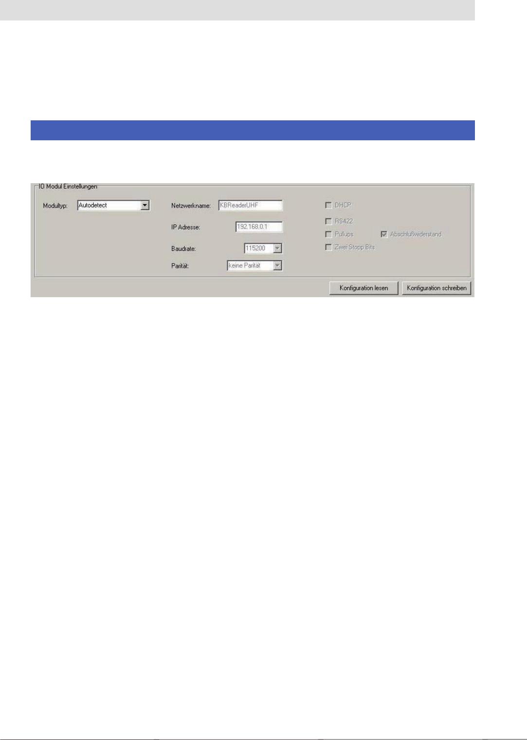
4.3.4.2 “IO-Modul-Einstellungen” (IO module settings) group box
The reader is supplied either with an Ethernet or RS 485/422 interface depending on its features.
The confi guration of the interface can be adapted to the application using this group box.
Note
Incorrect settings can result in an interruption of the connection to the reader. The settings on
readers without USB can only be reset using an interface that matches the confi guration.
Figure: Part of the “Konfi guration” (Confi guration) tab
The card type for the reader can be set in the “Modultyp” (Module type) drop-down list box. The
remaining confi guration boxes in this group box are activated depending on the card type selected.
The following settings are possible:
- Autodetect:
The reader detects which I/O card is installed. The settings for the card detected are made in
accordance with the default confi guration (see section 4.3.4.3).
- RS 485:
The reader expects a corresponding RS 422/485 card. To set the interface type from RS 485
to RS 422, the RS 422 check box must be selected. It is also possible to enable pull-ups and a
terminating resistor in the receive and transmit path. The terminating resistor is imperative for
a reliable point-to-point connection. It should only be deactivated in RS 485/422 networks in
which the reader is not installed at one of the ends of the network. The data transfer can also be
made using two stop bits. The transmission speed is set in the “Baudrate” drop-down list box.
The parity is set in the “Parität” (Parity) box to suit the required setting.
- Ethernet:
If the “Ethernet” module type is selected, it is possible to enter the network name and IP address.
If DHCP is activated by selecting the check box with the same name, the reader logs into the
DHCP server in the network and gets its IP address from there. For this reason the “IP-Adresse”
(IP address) fi eld is also deactivated. An appropriate network name can still be entered; this name
can then be used to communicate with the reader in the network provided there is an appropriately
confi gured DNS server.

23
4. Software
4.3.4.3 Default confi guration
The default confi guration includes all the settings for the RRUI4 as supplied.
- I/O module Autodetect
o RS 485/422 1 start bit
8 data bits
No parity
1 stop bit
115200 bits per second
o Ethernet DHCP
o Network name
RRUI4_xxxx
(xxxx ... seq. unit number, is the same as USB no)
- Transmission power
o Antenna 1-4 27 dBm
- Channel selection All channels selected, no preferred channels
- Modulation type Double sideband modulation
- Carrier shut down time 5 s
- Communication profi le Profi le 6
- Antenna confi guration No antenna group, only fi rst antenna active
4.3.4.4 Licence key
The licence key contains information on the confi guration of the reader and options that describe
the functionality of the reader's fi rmware. Depending on the customer's requirements, these features
can be enabled or inhibited by Kathrein.
If you need a different confi guration, you can type a new licence key prepared by Kathrein in this
group box.
Note
A licence key that does not match this hardware may result in the reader ceasing to function.
In this case, please contact our sales department (for contact data see last page).
24
4. Software
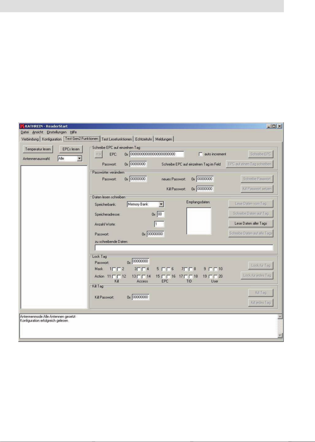
4.3.5 Test Gen2-Funktionen (Test Gen2 functions)
This tab makes it possible to test the individual reader functions. This includes, along with the
functionality in accordance with the EPC-Gen2 standard, e. g.: reading individual tags, writing
tags, setting passwords, also the measurement of the temperature inside the reader, as well as
the selection of the antenna.
Along with the “Temperatur lesen” (Read temperature), “EPCs lesen” (Read EPCs) buttons,
antenna selection and the box for displaying the EPCs read, this tab comprises the “Schreibe EPC
auf einzelnen Tag” (Write EPC to an individual tag), “Passwörter verändern” (Change passwords),
“Daten lesen schreiben” (Read write data), “Lock Tag” and “Kill Tag” group boxes. The sections
that follow explain this functionality in more detail.
Figure: The “Test Gen2-Funktionen” (Test Gen2 functions) tab
4.3.5.1 Reading tag
To read a tag on this tab, the “EPCs lesen” (Read EPCs) button must be clicked once the reader
is correctly confi gured. The reader now tries to read once all the tags in the fi eld of the selected
antenna. If the number of antennas is limited in the “Antennenwahl” (Antenna selection) drop-
down list box, only the available antennas or the antenna group set in the confi guration are
used for reading. The EPCs from the tags read successfully are displayed in the fi eld below.
The status box shows the EPCs of the tags read in relation to the antenna used.
The actual temperature inside the reader can be requested using the “Temperatur lesen” (Read
temperature) button. This function is for information only.
25
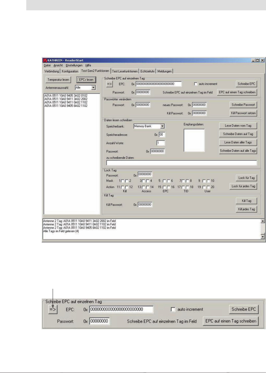
4.3.5.2 “Schreibe EPC auf einzelnen Tag” (Write EPC to an individual tag) group box
The fi gure below shows the tab after successfully reading tags:
Figure: The “Test Gen2-Funktionen” (Test Gen2 functions) tab with tags read
4. Software
There are two ways of writing a tag's EPC in this group box. The fi rst is to change an existing tag
or to write to any tag in the fi eld.
“übernehme EPC” (Copy EPC) button
Figure: The “Schreibe EPC auf einzelnen Tag” (Write EPC to an individual tag) group box

26
4. Software
To change an existing EPC, the EPC must be selected in the “gelesene EPCs” (EPCs read) box.
The EPC is copied to the editable “EPC” box using the “übernehme EPC” (Copy EPC) button. There
the code can be changed either manually or using the “auto-inkrement” (Auto-increment) function;
the latter function increases the EPC by 1 each time the code is written successfully to a tag. The
“Schreibe EPC” (Write EPC) button transfers the number from the EPC box to the selected tag. If the
“EPC auf einen Tag schreiben” (Write EPC to a tag) button is used it is not necessary to know the
EPC on the tag. But there must only be one tag in the fi eld. This tag is detected by the reader and
the new EPC written to the tag. If the data area on the tag is protected with an access password,
this password must be entered in the “Passwort” (Password) box prior to the write operation.
4.3.5.3 “Passwörter verändern” (Change passwords) group box
According to the EPC standard, the access to the individual memory areas of a tag can be restricted.
The confi guration of which area is protected is defi ned in the “Passwörter verändern” (Change
passwords) and “Lock Tag” group boxes.
The access password and the kill password can be set in the fi rst group box. For this purpose the
old password must be entered fi rst. If a password has not been set, 0 must be entered. The new
password is entered in the “neue Passwort” (New password) box. The old password is replaced
with the new password by clicking the “Schreibe Passwort” (Write password) button. To set a kill
password, the access password must also be entered. The kill password is only needed for the fi nal
deactivation of the tag.
Note
The tag will be unusable after a “Kill Tag” command!
The new kill password is entered in the fi eld and transferred to the tag by clicking the “Kill
Passwort setzten” (Set kill password) button. Once this process has been completed, the new
password applies.
4.3.5.4 “Lock Tag” group box
In this group box, the access to individual tag data areas can be inhibited as per the EPC standard.
Access is then only possible using a valid password, or is no longer possible until the inhibit
is removed.
The access is confi gured in 3 steps:
1. Enter the access password
2. Set mask bits for the “Kill”, “Access”, “EPC”, “TID” and “User” data areas. If a check box is selected,
the related action bit is defi ned as per the setting, otherwise it is ignored
3. Set action bits for the data areas. The function of the bits for each area is identical and is shown
in the following table. A set bit is the same as the selection of a check box on the user interface
You will fi nd more detailed information on these bits and the related memory areas in the latest
version of standard “Radio-Frequency Identity Protocols Class-1 Generation-2 UHF RFID” from
EPC global.

27
Table: Lock bit functionality
pwd-write Permalock Description
0 0 Area can be written with and without password
0 1 Area cannot be locked, but can be written with and without password
1 0 Area can only be written with valid password
1 1 Area cannot be written
After the defi nition of the functionality, this confi guration is written to the tag by clicking the
“Lock für Tag” (Lock for tag) button. This confi guration is transferred to every tag in the fi eld with
the same access password using the “Lock für jedes Tag” (Lock for every tag) button.
4.3.5.5 “Daten lesen und schreiben” (Read and write data) group box
Each memory bank in the tag can be read and written in this group box. The exact layout of
the tag memory is given in the EPC Global standard “Radio-Frequency Identity Protocols
Class-1 Generation-2 UHF RFID”.
4.3.5.6 “Kill Tag” group box
The tags can be fi nally deactivated in this group box.
Note
The tag will be unusable after a “Kill Tag” command!
To start this operation, the correct kill password must be entered. The “Kill Tag” button only
deactivates the tag marked on which the kill password matches the password entered. Groups
of tags can be deactivated using the “Kill jedes Tag” (Kill every tag) button; here it is also required
that the tags have the same kill password.
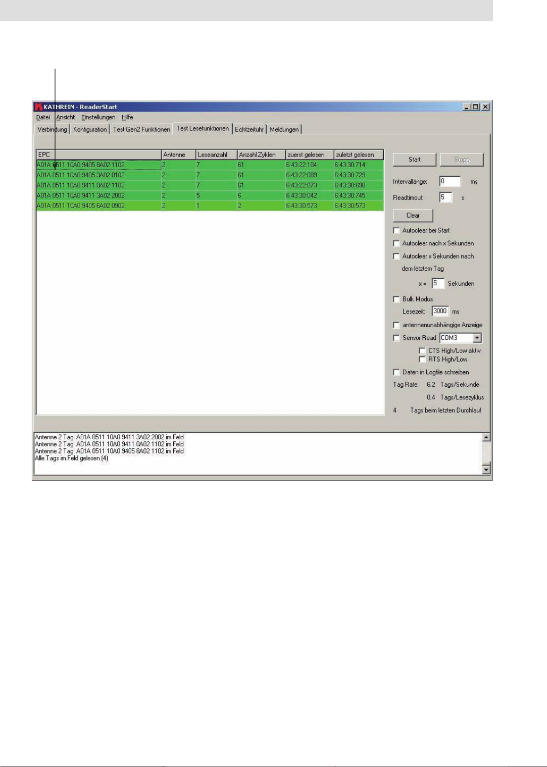
4.3.6 Test Lesefunktion (Test read function)
Using the functions available on this tab the “Read Performance” can be tested. Part of the tab
is designed for cyclically polling the tags in the fi eld.
4. Software
28
EPCs read
Figure: “Test Lesefunktionen” (Test read functions)
4. Software
The largest part of the tab is taken up by the “gelesene EPCs” (EPCs read) box. This box contains
a table that displays each tag read. Additional information is shown for each tag:
- Antenne (Antenna) This number is the same as the antenna port on the
reader via which the tag has been read
- Leseanzahl (Number of reads) Indicates the number of successful read processes
completed
- Anzahl Zyklen (Number of cycles) Indicates the total number of read cycles since the
start of the read process
- zuerst gelesen (Read fi rst) Time the tag was read for the fi rst time
- zuletzt gelesen (Last read) Time the tag was active in the fi eld for the last time
The right part of the tab contains various options that affect the reader's mode of operation.
The “Start” and “Stop” buttons start and end the reader's read cycle. The “Intervalllänge” (Interval
length) box defi nes how long the software waits after a read command until the next read command
is sent to the reader. The interval length can be between 0 and 9999 ms.
29
4. Software
Table: Connector pin assignment Sub-D 9-pin
Signal I/O Pin Sub-D 9
TD O 3
RD I 2
SG 5
DTR O 4
DSR I 6
CD I 1
RTS O 7
CTS I 8
If there is a very large number of tags in the fi eld, the reader may take a very long time to singularise
and read the EPCs on the tags. In such a case the software may end the read process with a
timeout. In the “Readtimeout” (Read timeout) box you can defi ne how long the software waits for a
reply from the reader before the read command is declared invalid and the software outputs an
error message. This time is entered in seconds and can be a maximum of 99 seconds.
The “gelesene EPCs” (EPCs read) table can be completely erased manually using the “Clear” button.
The check boxes underneath this button make it possible to reset the table:
- Either on each start
- After a specifi c time in seconds
- Or a specifi c time after the last tag was read.
The related function is activated by selecting the related check box. The maximum waiting time
before the table is cleared is 999 seconds.
The “Bulk-Modus” (Bulk mode) changes the reading behaviour of the reader such that the EPCs
for the tags successfully read are not logged into the reader immediately after the end of a read
process. The reader automatically starts read commands on all available antennas until the time
stated in the “Lesezeit” (Read time) fi eld has elapsed. All the tags read are then transferred to the
software. If there is a large number of tags in the fi eld, the transmission time from the reader
to the PC is optimised using this function and the performance of the reader improved.
The “Antennen unabhängige Anzeige” (Antenna-independent indication) check box makes it
possible to suppress the multiple indication of tags that are read via more than antennas. With
this indication, each tag, irrespective of which antenna is used to read it, is added to the EPC list
and counted only once.
A trigger event can send the read command to the reader using the “Sensor Read” function.
For this purpose a suitable signal must be applied to a spare serial port on the PC. If the condition
is met, the PC sends read commands to the reader until the condition is no longer met.
To set the correct signal level, a check box can be used to switch between RTS and CTS. CTS is the
input as per table 7. RTS is set to the required active level. The correct level to trigger the trigger event
is set on CTS using the check box.
To confi gure this function, the level for RTS and CTS must fi rst be defi ned. In the next step, the
required port must be selected in the drop-down list box. The com port is opened by selecting the
“Sensor Read” check box, and the related settings made.

30
4. Software
4.3.7 Echtzeituhr (Real-time clock)
Here the reader's real-time clock can be read and set. Click the “Zeit lesen” (Read time) button to read
the RTC from the reader and display it in the “Uhrzeit” (Time) and “Datum” (Date) fi elds.
The time can be set by manually entering the time in the “Uhrzeit” (Time) and “Datum” (Date) fi elds.
An easier variant is to select the “PC Zeit setzen” (Set PC time) check box. Then the current time is
transferred to the related boxes. The time is transferred to the reader by clicking the “Uhrzeit setzen”
(Set time) button.
4.3.8 Meldungen (Messages)
All reader error messages are logged on this tab. These include whether the connection to the PC
was established successfully, whether the connection to the PC has been interrupted, whether
it was not possible to fi nd a free transmission channel or whether the reader has detected an
antenna fault.
4.3.9 Menu bar
4.3.9.1 Datei (File)
On this menu you can open and save the confi guration as well as the settings for the software in
the form of a XML fi le. The “Beenden” (Exit) command closes the application.
4.3.9.2 Ansicht (View)
On this menu the contents of the status box can be deleted. All messages that occur during
operation are saved in this box and deleted at specifi c intervals. If you want to reset the box,
use the “Ansicht” (View) menu.
4.3.9.3 Einstellungen (Settings)
On the “Einstellungen” (Settings) tab the access to the reader's write operations on the tag can be
inhibited for unauthorised personnel. If a write password is set, the user cannot perform any write
operations on the tag without entering the password and the related buttons are not available.
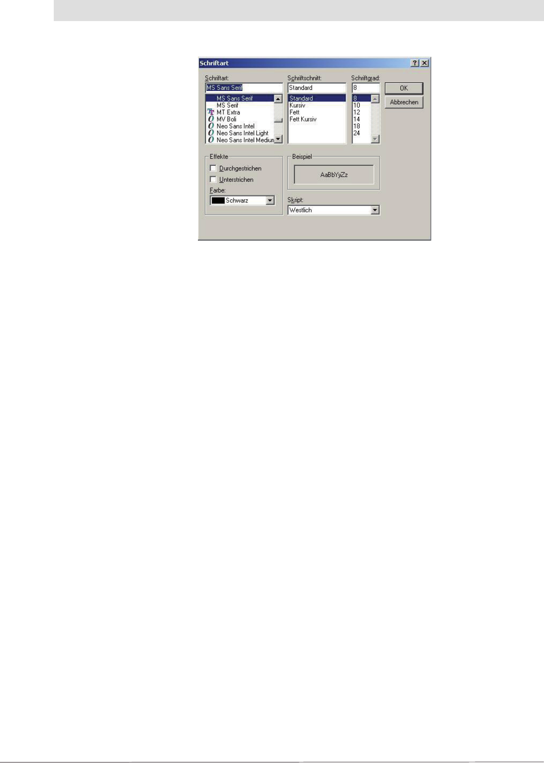
The following dialog box is displayed by clicking the “Schriftart EPCs lesen ändern” (Change read
EPCs font) command (see next page):
By selecting the “Daten in Log File schreiben” (Write data to log fi le) check box the data from
the status box are saved in the fi le “log.txt” in the program folder.
31
4. Software
Figure: Changing font
Here the format of the font for the EPC fi eld on the “Test Lesefunktionen” (Test read functions)
tab can be changed. It is possible to improve the legibility of the read results on the monitor even
from larger distances by increasing the size of the font.
4.3.9.4 Hilfe (Help)
The “Hilfe” (Help) menu contains the Info..., Reader Info and Firmwareupdate (Firmware update)
commands.
The “Info” command provides the version information on the ReaderStart application, as well as
copyright information. The “Readerinfo” command requests information on the software in the
reader to which a connection is currently established and displays this information.
Once a connection has been established to the reader, a reader software update can be started
using the “Firmwareupdate” (Firmware update) command on the “Hilfe” (Help) menu. If you click this
command, a fi le selection dialog box appears in which you can select the fi le with the new fi rmware
with the fi le extension “.bin”. You can obtain this fi le either from our support department or from the
web site “www.kathrein.de”. Up to software version 1.23.00 it is only possible to update with a later
version of the software. With all later software versions it also possible to downgrade the fi rmware.
Once a fi le has been selected, start the download process by clicking the “Öffnen” (Open) button.
The software is transferred initially to the reader's RAM, the progress is indicated in the status box.
If no errors have occurred during this process, the software is transferred to the fl ash in the 2nd step.
Whether the update process was successful can be seen in the status box, the reader's LED also
illuminates green. The duration of the update process is dependent on the interface selected.

5. Contact Addresses
Headquarters:
KATHREIN-Werke KG
RFID-Systeme
P.O. Box 100 444
D-83004 Rosenheim
Fax: +49 8031 184-52794
e-mail: rfi d@kathrein.de
Innovation centre:
KATHREIN-RFID GmbH
Am Kroit 25-27
D-83123 Amerang
e-mail: rfi d@kathrein.de
www.kathrein-rfi d.de
936.3456/A/1108/ZWT - Technical data subject to change.
Internet: http://www.kathrein-rfi d.de
KATHREIN-Werke KG • phone +49 8031 184-0 • Fax +49 8031 184-306
Anton-Kathrein-Straße 1-3 • P.O. Box 100 444 • 83004 Rosenheim GERMANY