KC Wirefree BTAUDIO BTAUDIO User Manual BTAUDIO UserGuidex
KC Wirefree Corporation BTAUDIO BTAUDIO UserGuidex
User Manual

BTAudioModuleUserGuide
Class1BluetoothAudioModule
www.kcwirefree.comVersionDecember19,2014Page1
Description
TheBTAUDIO‐5112Class1BluetoothHiPowerAudioModuleisahighlytunedandcompletelyintegratedwirelessaudio
transceiversubsystemreadyforinstallationinaudiodevices.TheBTAUDIO‐5112isapre‐engineeredsubsystemintegratinga
wirelessradio,digitalaudiosystem,andprogrammedfirmwareprofilesthatdefinefeatures,configurations,anduserinterface.All
firmwareofferedbyKCWirefreecanbecustomizedforOEMclients.Inmanycasesafewchangescanproducegreatvalueby
differentiatingandimprovingyourproduct.FirmwarecanbeupdatedviaUSB.
kcAudioGatewayFirmwareEdition
ThekcAudioGatewayfirmwareisatransmittersystem,offeringA2DPsourceprofileorAGHFPgatewayprofile(default),butnot
bothsimultaneously.A2DPmodeprovidesstereotransmissiontoHeadset/Speakerdevices.Stereoaudioissampledfromthe
MIC_L+,MIC_L‐,MIC_R+,andMIC_R‐pinsat44.1kHz,andwillautomaticallytransmittoaHeadsetdevice.AGHFPmode(default)
providestwo‐wayvoicecommunications,sampledat8kHz,toastandardBluetoothcellphoneheadset.Additionally,theHeadset
VoiceCommandpromptwilltoggleaPTTpinonkcAudioGateway,whichenablesstandardBluetoothcellphoneheadsetsto
provideaPTTfunction.
PleaserefertoourkcAudioGatewayUserGuidefordetails.
kcAudioHeadsetFirmwareEdition
ThekcAudioHeadsetfirmwareisareceiversystem,offeringA2DPsinkprofile,andHFPprofile.ItcanreceiveanA2DPwireless
stereosignal,decompress,andconverttoanalogaudioavailableontheSPK_L+,SPK_L‐,SPK_R+,andSPK_R‐pins.Additionally,it
can“answer”phonecalls,whichwillpauseanyA2DPstream,andswitchmodes,nowprovidingtwowaymonocommunication
channel.
PleaserefertoourkcAudioHeadsetUserGuidefordetails.
BTAudioModuleUserGuide
Class1BluetoothAudioModule
www.kcwirefree.comVersionDecember19,2014Page2
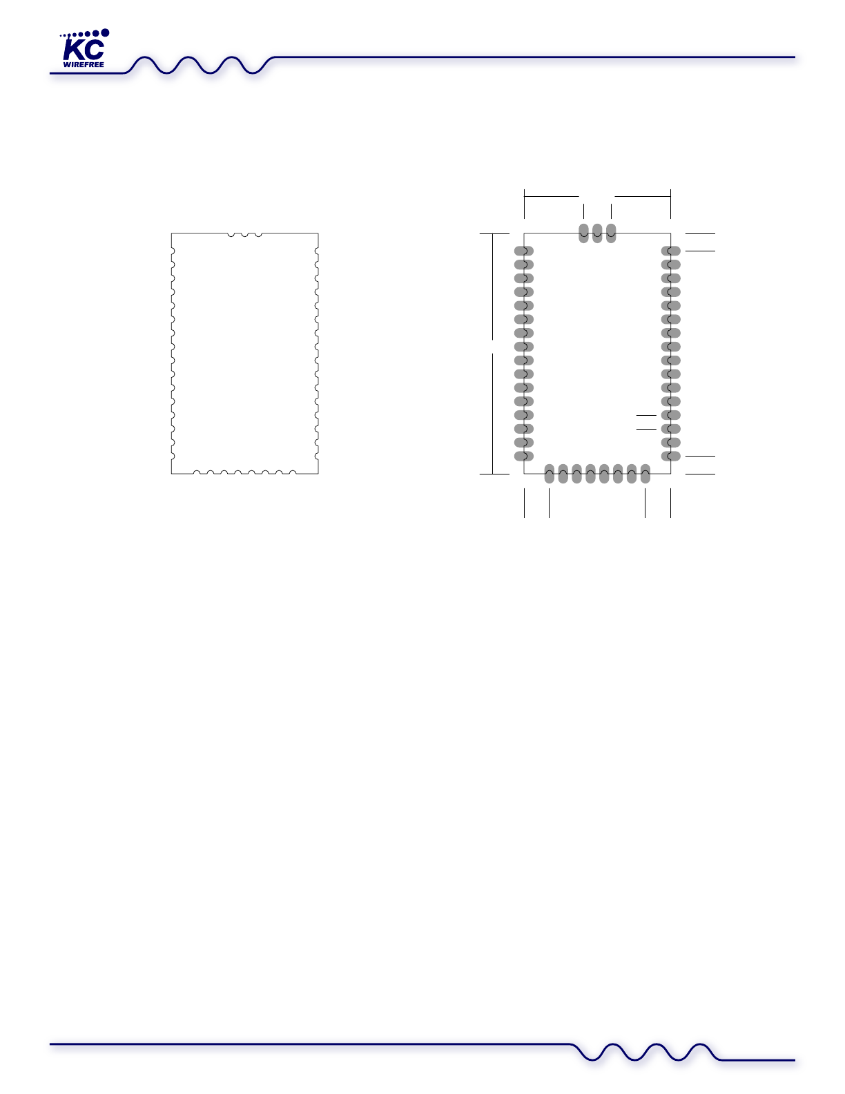
Dimensions & Layout
BTAUDIO‐5112
TopView
43
42
41
GND
ANT
GND
1
2
3
4
5
6
7
8
9
10
11
12
13
14
15
16
40
39
38
37
36
35
34
33
32
31
30
29
28
27
26
25
17
18
19
20
21
22
23
24
GND
RESET
VDD
ENABLE
SPI_CSB
SPI_MOSI
SPI_MISO
SPI_CLK
PIO2
PIO3
PIO4
PIO5
PIO6
PIO7
PIO8
PIO9
PIO10
LED_BLU
LED_RED
UART_RTS
UART_CTS
UART_TXD
UART_RXD
3V3_OUT
SPK_R+
SPK_R-
SPK_L+
SPK_L-
MIC_R+
MIC_R-
MIC_L+
MIC_L-
MIC_BIAS
PCM_IN
PCM_CLK
PCM_OUT
PCM_SYNC
USB+
USB-
CHARGE
1.4
PADS
1.0 X 2.0
1.8
2.69.82.6
21.0
1.8
15.0 MM
2.8 6.16.1
24.6

BTAudioModuleUserGuide
Class1BluetoothAudioModule
www.kcwirefree.comVersionDecember19,2014Page3
PinAssignments
PinFunctionTypeDescription
1PIO2I/OProgrammableI/O
2PIO3I/OProgrammableI/O
3PIO4I/OProgrammableI/O
4PIO5I/OProgrammableI/O
5PIO6I/OProgrammableI/O[I2C]
6PIO7I/OProgrammableI/O[I2C]
7PIO8I/OProgrammableI/O[I2C]
8PIO9I/OProgrammableI/O
9PIO10I/OProgrammableI/O
10LED_BLUInputBlueLEDDrain
11LED_REDInputRedLEDDrain
12UART_RTSOutputUARTRequestToSend
13UART_CTSInputUARTClearToSend
14UART_TXDOutputUARTDataTransmit
15UART_RXDInputUARTDataReceive
163V3_OUTOutputOnboard3.3VRegulatorOutput
17GND‐‐Ground
18RESETInputReset(ActiveLow>5ms)
19VDDInputVDD/BatteryInput(2.9V–4.4V)
20ENABLEInputSystemEnable(withinternallatch)
21SPI_CSBInputSPIChipSelect
22SPI_MOSIInputSPIMasterOut
23SPI_MISOOutputSPIMasterIn
24SPI_CLKInputSPIClock
25CHARGEInputBatteryChargingSupply(onlyusewhenVDDisbatterypowered)
26USB‐ I/OUSBDataNegative
27USB+I/OUSBDataPositive
28PCM_SYNCI/OPCMSync[I2SWS]
29PCM_OUTOutputPCMOut[I2SOut][SPDIFOut]
30PCM_CLKI/OPCMClock[I2SClk]
31PCM_INInputPCMIn[I2SIn][SPDIFIn]
32MIC_BIASOutputMicrophoneBias
33MIC_L‐ InputAudioInputLeftNegative
34MIC_L+InputAudioInputLeftPositive
35MIC_R‐ InputAudioInputRightNegative
36MIC_R+InputAudioInputRightPositive
37SPK_L‐ OutputAudioOutputLeftNegative
38SPK_L+OutputAudioOutputLeftPositive
39SPK_R‐ OutputAudioOutputRightNegative
40SPK_R+OutputAudioOutputRightNegative
41GND‐‐Ground
42ANTI/O50Ohm2.4GHzAntennaPort
43GND‐‐Ground
[Optionfeaturesinbrackets]

BTAudioModuleUserGuide
Class1BluetoothAudioModule
www.kcwirefree.comVersionDecember19,2014Page4
InterfacePins
PIOPins[1‐9]
PIOpinsareLOWbydefault,andbuttonpressesusedfordeviceoperationareHIGHsignals.PIOinputsaredebouncedto20ms.
SeveralPIOpinsareassignedfunctionsindefaultversionsoffirmware.Customprogrammedfunctionsareavailable.Inputscan
beconfiguredforweakpull‐up,weakpull‐down,strongpull‐up,strongpull‐down.Voltageinputtoleranceandoutputlevelis
directlyrelatedtotheVDDlevel.
SpecificfunctionsareenabledondesignatedPIOpinsdependingonfirmwareversion.PleaserefertothespecificfirmwareAudio
UserGuidesforcompleteinformationregardingPIOfeaturesandassignments.
LEDPins[10‐11]
Twoopen‐drainLEDoutputpinsareavailable.TheLED'sneedapositive3.3V(maximum)supply,andacurrentlimitingresistor.
UARTPins[12‐15]
TheUARTiscompatiblewiththe16450industrystandard.UpcomingkcAudiofirmwarewillimplementanATCommandsetfor
configurationandoperation.
3V3_OUTPin[16]
Themodulehasseveralonboardregulators.Theonboard3V3regulatorsuppliesthePIO,PCM,SPI,UART,andUSBPins.Theclass
2modulehasupto100mAavailablefromthispin.Theclass1modulealsousestheonboard3V3regulatortosupplytheRF
PowerAmp,andhaslessthan30mAavailablefromthispin.
GNDPin[17]
VSSgroundplane.
RESETPin[18]
ThemodulewillresetwhenpulledLOW>5ms.
VDDPin[19]
MinimumVDDis2.9V.
Suppliesseveralonboardregulators,andisalsothedesignatedBatteryPterminalifpoweringdirectlyfromaLithiumIonbattery.
TheVDDpinmayreceivearechargecurrentsupplywhenthevoltagereadingfromthispinmeasuresbelow4.0V,theCHARGEPin
isconnectedtoapowersupply,andfirmwarehasenabledbatterymonitoringandcharging(defaultbehavior).ThisVDDpin
suppliestheonboardSeikoS‐1112LDO3V3regulator.Note:theSeikoS‐1112hasa200mVdropout,soifVDDis<3.5V,thenthe
3V3supplyrailwillhavea0.2Vdropout.The3V3railsuppliesPIO,PCM,SPI,UART,andUSBPins.Powersupplytomoduleshould
havelessthan10mVrmsnoisebetween0‐10MHz,andspikesshouldbeminimal.

BTAudioModuleUserGuide
Class1BluetoothAudioModule
www.kcwirefree.comVersionDecember19,2014Page5
ENABLEPin[20]
Enablesinternalvoltageregulators.TheENABLEpincanbeutilizedintwodifferentways.Ourcurrentdefaultfirmwareusesthe
ENABLEpininSwitchPowerMode,whereitshouldbetiedtotheVDDpin,andusedwithanexternalpowerswitch.InSwitched
PowerMode,ourBTBfunctionsaretypicallyassignedtoPIO4.PleaseseespecificfirmwareUserGuidesfordetailsregardingPIO
functionassignments.
Alternatively,firmwarecanutilizetheENABLEpininBatteryPowerMode,whichusesamomentaryON/OFFbuttontopowerup.
Oncepoweredup,theinternalvoltageregulatorswilllatchon,andthentheENABLEpinisusedforBTBassignedfunctions.Thisis
typicallyintendedforabatterypoweredheadsetapplicationwithminimalbuttons.Separatefirmwaremustbeusedthatassigns
thisbehaviortotheENABLEpin.
SPIPins[21‐24]
WehighlyrecommendincludingtestpointsforthefourSPIsignals,usedforfirmwareloadinganddiagnostics.TheSPIinterfaceis
unavailableforgeneralusage,andonlyinterfaceswithchipmanufacturerdiagnosticapplications.
CHARGEPin[25]
Providepowersupplyforbatterycharging,whenabatteryisconnectedtoVDD,andfirmwareenablesbatterymonitoringand
chargingfunction(enabledbydefault).DonotconnectwithoutaLithiumIonbatteryconnectedtoVDDPin.
USBPins[26‐27]
Theseinterfacesareavailablewithcustomconfiguration.USBcanbeprogrammedforplug‐n‐playoperationusingstandardUSB
AudiodriversavailableonPC,Mac,andLinux.
PCMPins[28‐31]
Pinsaregenerally3.3Vlevellogic(dependentuponVDD).
MIC_BIASPin[32]
ProvidesaDCbiasintendedforelectretmicrophones.Configurable1.8V–3.3V(default=2.69V)withacurrentof200uA–
1.229mA(default=0.672mA).
MICPins[33‐36]
Microphoneorlinelevelanalogaudioinput.Impedanceis6.0kΩ‐30kΩdependingonvolumesetting.ADCoperatesat8,11.025,
16,22.05,32,and44.1kHz.Inputsignalshouldbe4mVrms–800mVrms.Inputgainisadjustablefrom
SPKPins[37‐40]
Outputgainisadjustablefrom‐45dBto+3.5dB.
RFPort[41‐43]
Themodulealreadycontainsabalun‐filteronboard,sotheantennaportonlyrequiresastandard2.4GHzRFtransmissionline
witha50ohmload.Designtheantennacircuitaccordingtotheantennamanufacturerguidelines.Somedesignsmayuseasimple
chipantennawithoutadditionalcircuitry.Microstripdesignisnotcriticaliftheantennaislessthan3mmfromtheRFpin.Afew
recommendedchipantennas:Johanson2450AT18B100E,Johanson2450AT43A100E,orAntenovaRufaA5839.ForPCB
transmissionlinedesign,werecommendthefollowingonlinecalculator:http://www.emclabinfo.com/emc_calc/microstrip.htm

BTAudioModuleUserGuide
Class1BluetoothAudioModule
www.kcwirefree.comVersionDecember19,2014Page6
ElectricalCharacteristics (ConditionsVDD=3.3Vand25°C)
AbsoluteMaximumRatingsMinMaxUnit
Storagetemperaturerange ‐40+105°C
SupplyvoltageVDD‐0.44.4Volts
SupplyvoltageCHARGE4.56.5Volts
SupplyvoltageENABLE‐0.44.9Volts
RecommendedOperatingConditionsMinTypicalMaxUnit
Temperaturerange ‐4020+85°C
SupplyvoltageVDD2.93.34.4Volts
SupplyvoltageCHARGE4.5‐‐6.5Volts
SupplyvoltageENABLE2.5‐‐4.4Volts
CurrentConsumption AvgUnit
Stereo66mA
MonoHeadset36mA
NoConnection2mA
Peakcurrent190mA
RFCharacteristicsMinMaxUnit
CarrierFrequency24002483.5MHz
TransmissionLine5050Ω
TransmissionPower0+20dBm
ReceiveSensitivity‐20‐98dBm
AudioDACCharacteristicsMinTypicalMaxUnit
Outputvoltagefull‐scaleswing(differential)‐‐750‐‐mVrms
Resolution‐‐‐‐16Bits
SampleRate8‐‐48kHz
SNR(@8KHzsampling)‐‐95‐‐dB
DigitalGain‐24‐‐21.5dB
AnalogGain0‐‐‐21dB
THD+N(@100kΩload)‐‐0.040.01%

BTAudioModuleUserGuide
Class1BluetoothAudioModule
www.kcwirefree.comVersionDecember19,2014Page7
AudioADCCharacteristicsMinTypicalMaxUnit
Inputfullscaleatmaximumgain(differential)‐‐0.004‐‐ Vrms
Inputfullscaleatminimumgain(differential)‐‐0.800‐‐ Vrms
Resolution‐‐‐‐16Bits
SampleRate(8,11.025,16,22.050,32,44.1kHz)8‐‐44.1kHz
SNR(@8KHzsampling)‐‐79‐‐dB
DigitalGain‐24‐‐21.5dB
AnalogGain‐‐‐‐42dB
3dBbandwidth‐‐20‐‐kHz
Inputimpedance‐‐6.030Ω
THD+N(microphoneinput)@30mVrmsinput‐‐0.04‐‐ %
ProgrammableI/OPinsOperatingCharacteristicsMinTypicalMaxUnit
InputVoltageLowLogic‐0.3‐‐VDDLDOx0.25Volts
InputVoltageHighLogicVDDLDOx0.625‐‐ VDDLDO+0.3Volts
OutputVoltageLowLogic0‐‐0.125Volts
OutputVoltageHighLogicVDDLDOx0.75‐‐ VDDLDOVolts
OutputCurrentLowLogic‐‐4.0‐‐ mA
OutputCurrentHighLogic‐‐‐4.0‐‐ mA
InputLeakageCurrent‐1000100nA
InputSchmittvoltageVDDLDOx0.25‐‐VDDLDOx0.625 Volts
InputCapacitance1.0‐‐5.0pF
Weakpullup500K‐‐ 2MΩ
Weakpulldown500K‐‐ 2MΩ
Strongpullup10K‐‐50KΩ
Strongpulldown10K‐‐50KΩ
FCC Statement:
This equipment has been tested and found to comply with the limits for Part 15 of the FCC rules.
These limits are designed to provide reasonable protection against harmful interference in a
residential installation. This equipment generates, uses and can radiate radio frequency energy
and, if not installed and used in accordance with the instructions, may cause harmful interference
to radio communications.
However, there is no guarantee that interference will not occur in a particular installation. If this
equipment does cause harmful interference to radio or television reception, which can be
determined by turning the equipment off and on, the user is encouraged to try to correct the
interference by one or more of the following measures:
• Reorient or relocate the receiving antenna.
• Increase the separation between the equipment and receiver.
• Connect the equipment to an outlet on a circuit different from that to which the receiver is
connected.
This device complies with part 15 of the FCC rules. Operation is subject to the following two
conditions: (1) This device may not cause harmful interference, and (2) this device must accept
any interference received, including interference that may cause undesired operation.
Note: Modifications to this product will void the user’s authority to operate this equipment.
RF Radiation Exposure Statement:
1.This Transmitter must not be co located or operating in conjunction with any other antenna or ‐
transmitter.
2.This equipment complies with FCC RF radiation exposure limits set forth for an uncontrolled
environment. This equipment should be installed and operated with a minimum distance of 20
centimeters between the radiator and your body.
FCC Information to OEM integrator
The OEM integrator has to be aware not to provide information to the end user regarding how to
install or remove this RF module in the user manual of the end product.
The user manual which is provided by OEM integrators for end users must include the following
information in a prominent location.
1.To comply with FCC RF exposure compliance requirements, the antenna used for this
transmitter must be installed to provide a separation distance of at least 20 cm from all persons
and must not be co located or operating in conjunction with any other antenna or transmitter, ‐
except in accordance with FCC multi transmitter product procedures.‐
2. Only those antennas with same type and lesser gain filed under this FCC ID number can be
used with this device.
3. The regulatory label on the final system must include the statement: “Contains FCC ID:S22-BTAUDIO or
using electronic labeling method as documented in KDB 784748.
4. The final system integrator must ensure there is no instruction provided in the user manual or
customer documentation indicating how to install or remove the transmitter module except such
device has implemented two ways authentication between module and the host system‐