KEYES DIY Robot HC06 bluetooth module User Manual HC 06 Spec
Shenzhen KEYES DIY Robot Co.,Ltd bluetooth module HC 06 Spec
UserManual.wiki
>
KEYES DIY Robot
>
HC06 User Manual
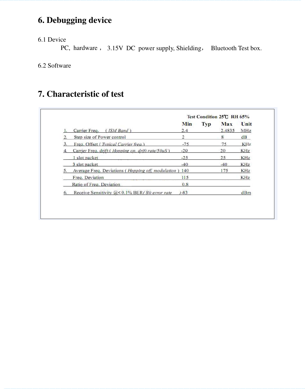
User manual
Navigation menu
Upload a User Manual
Namespaces
Wiki Guide
HTML
PDF
Info
Views
User Manual
Discussion / Help
Navigation