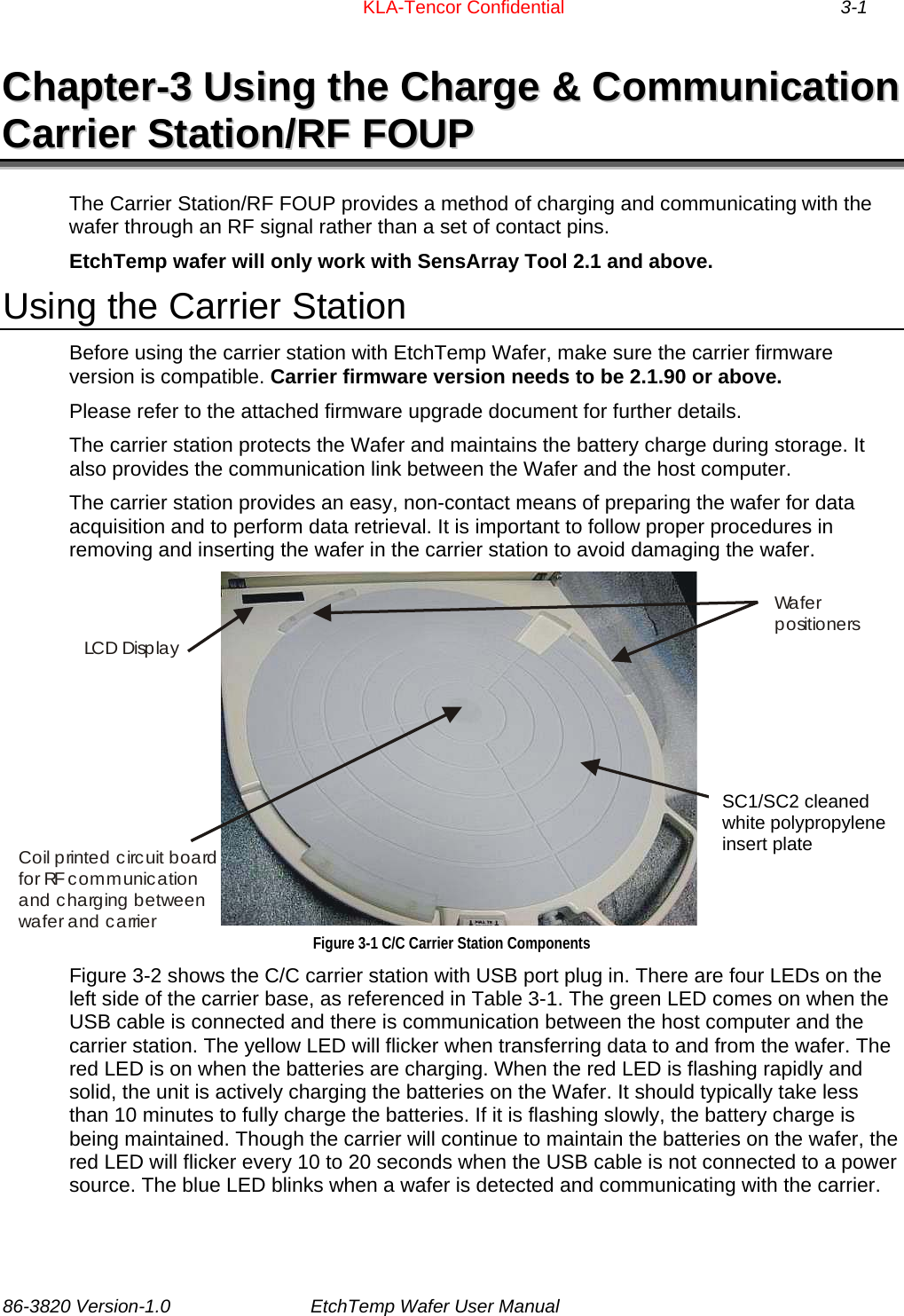
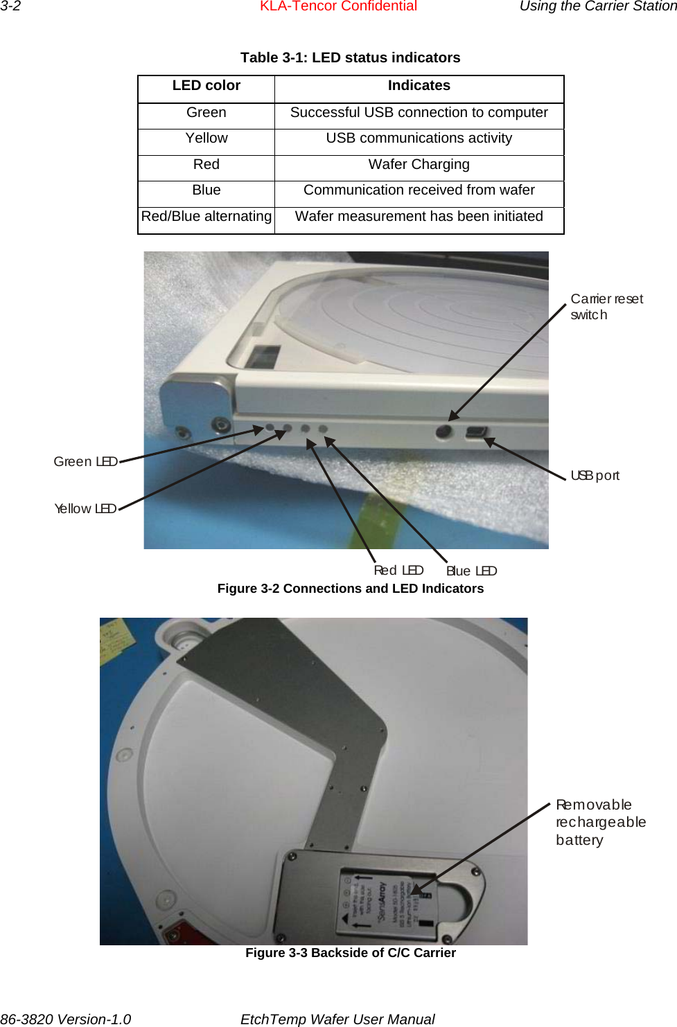
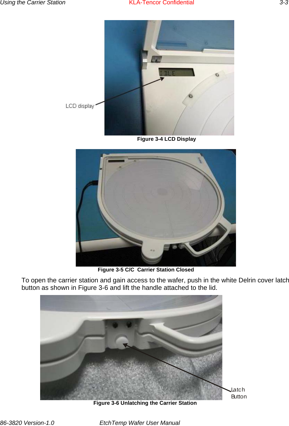
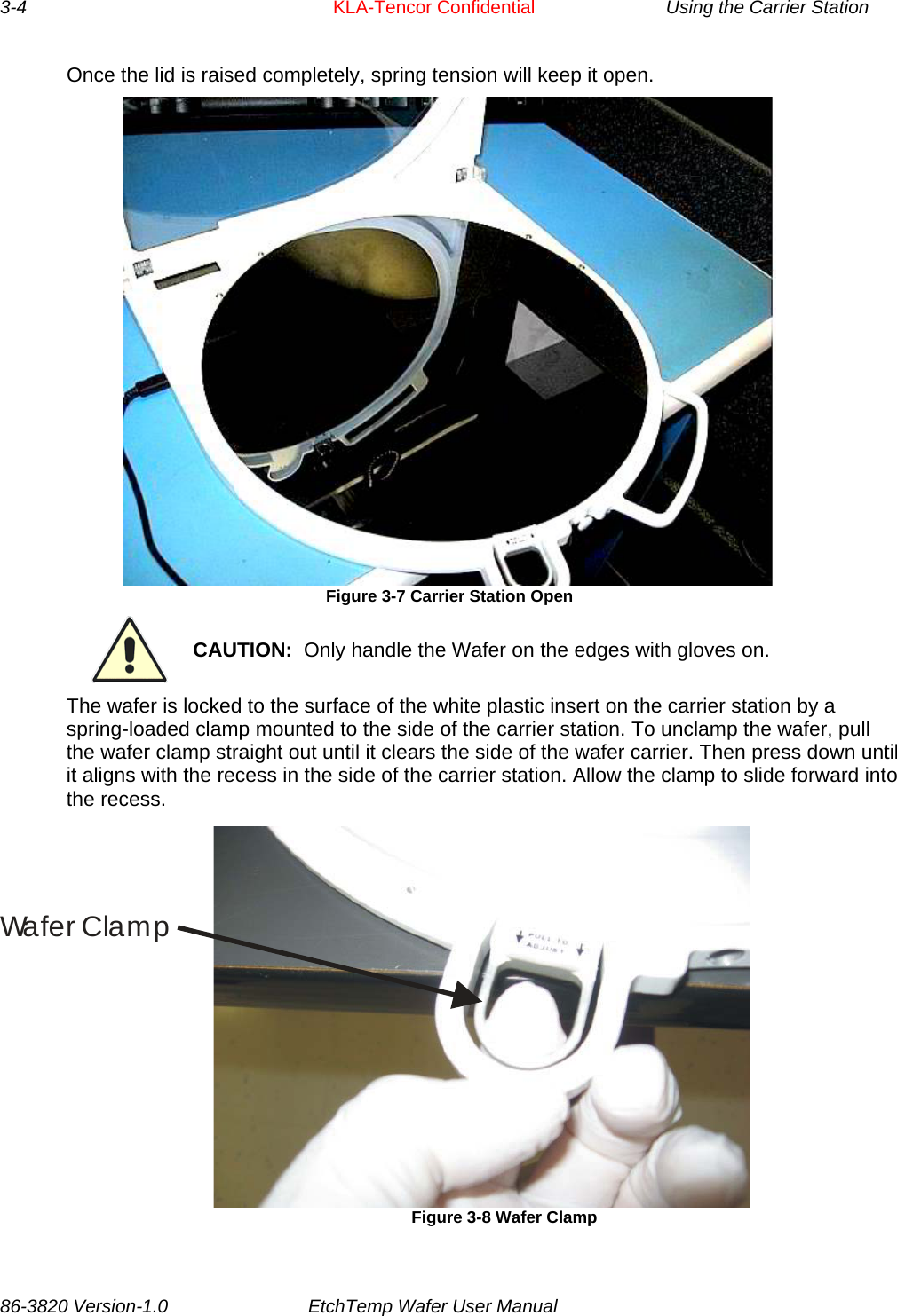
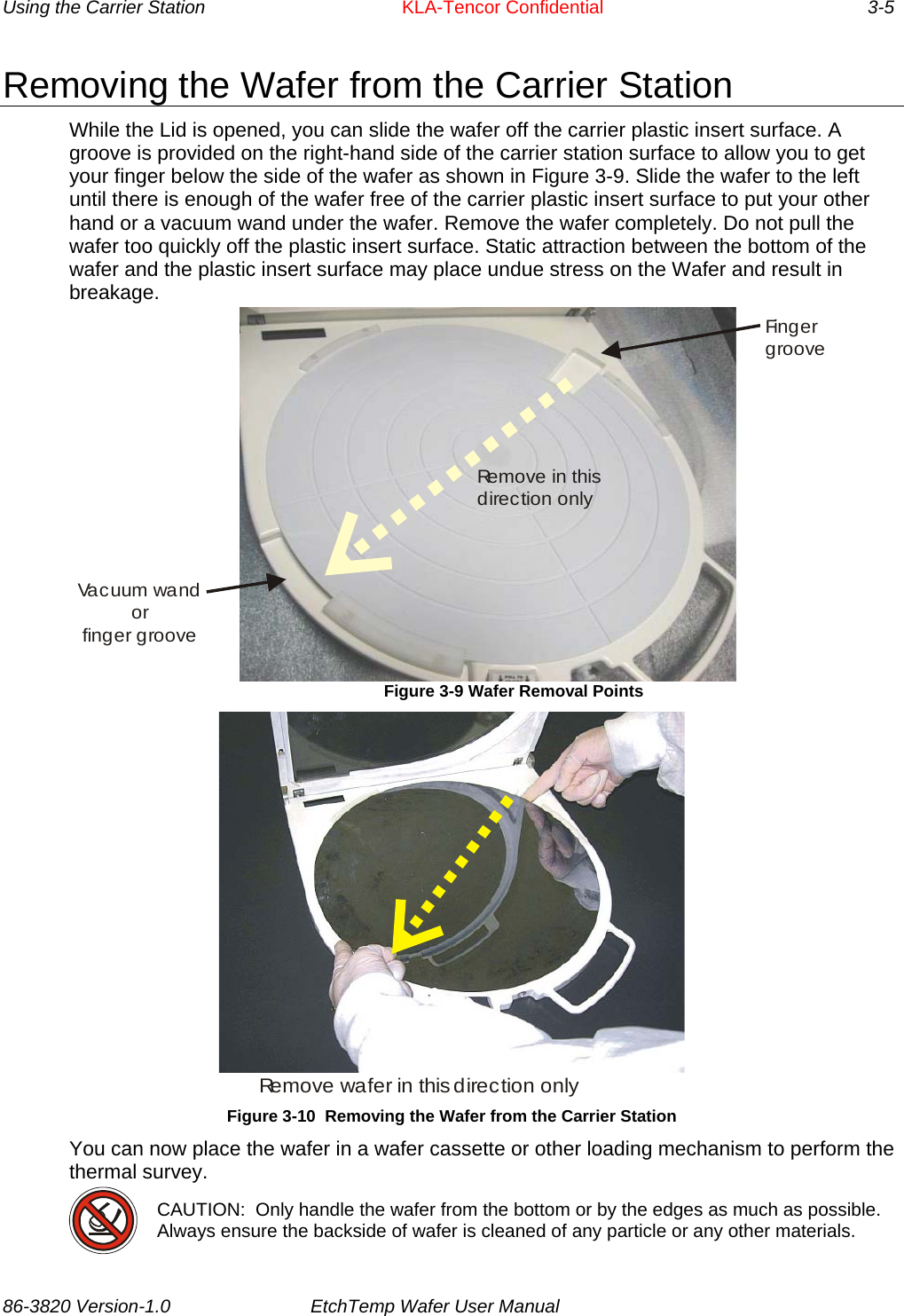
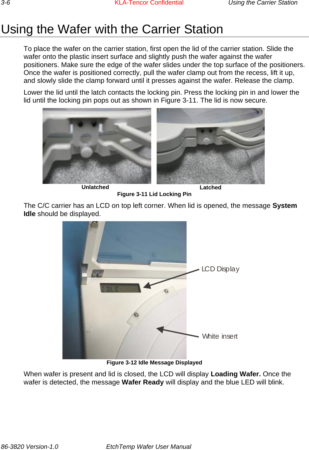
KLA RFWC812A Integral Wafer RF Carrier System for 200 and 300mm Wafers User Manual EtchTemp Wafer Title Page
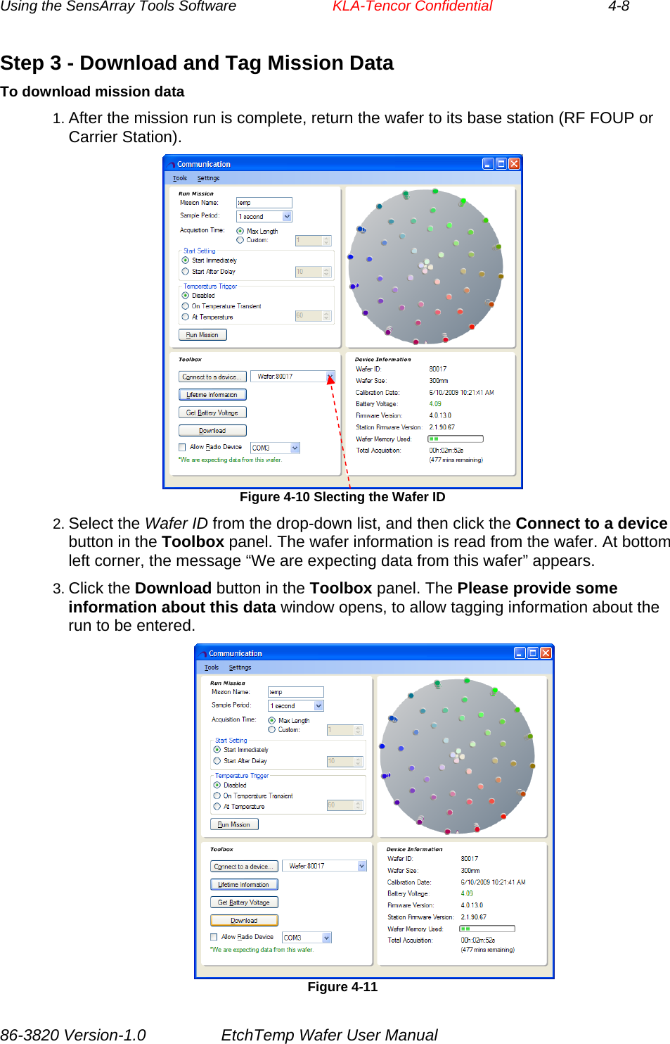
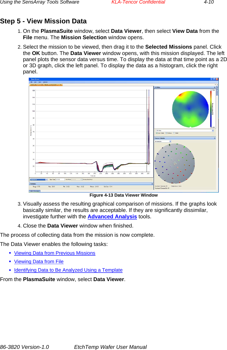
KLA-Tencor Corporation Integral Wafer RF Carrier System for 200 and 300mm Wafers EtchTemp Wafer Title Page
KLA >
Contents
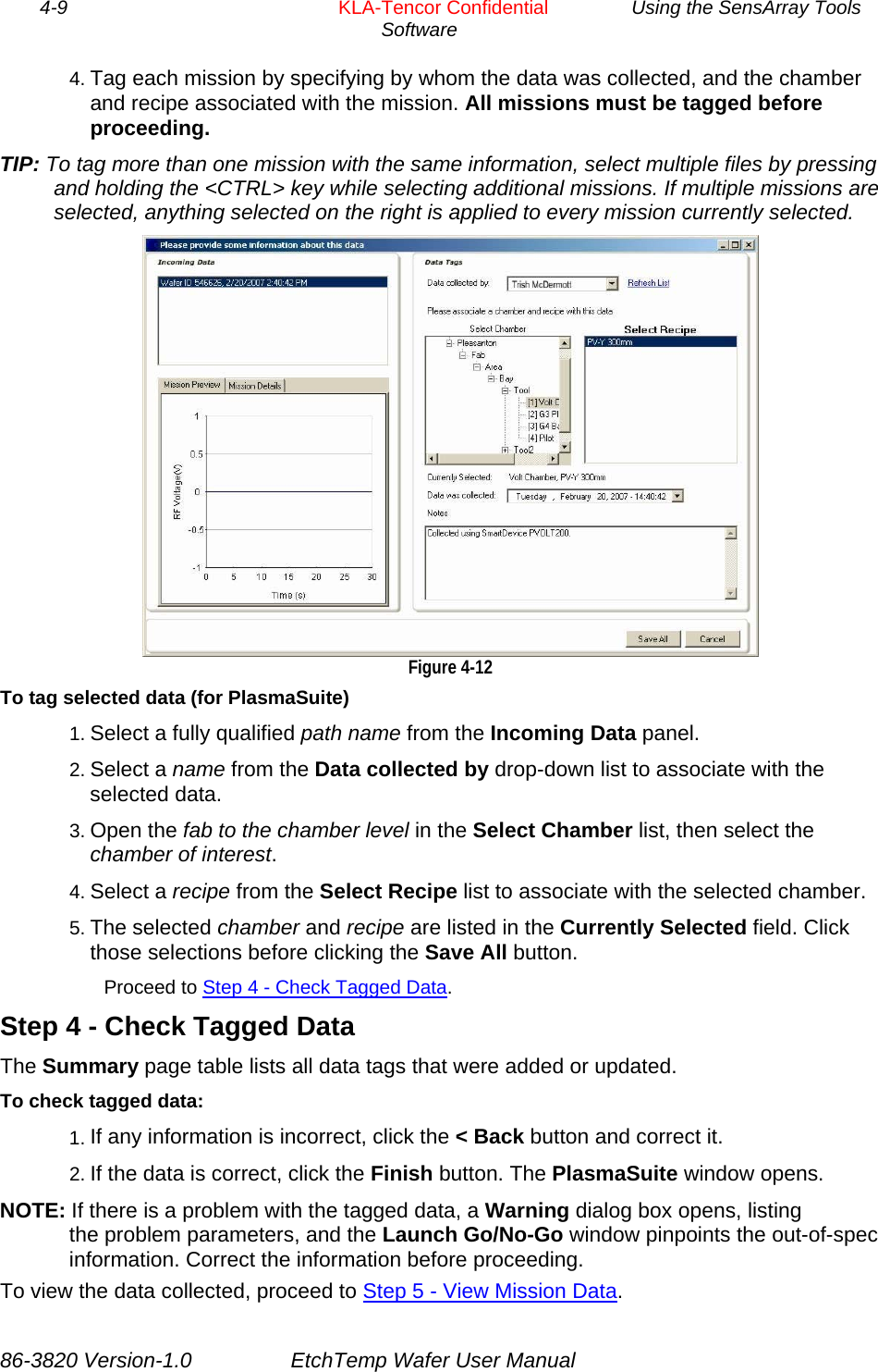
- 1. Users Manual
- 2. Users Manual 2
Users Manual
![Important Notices Warranty EtchTemp Wafer System Hardware KLA-Tencor warrants that the EtchTemp Wafer Systems (“Products”) sold will be free from defects in material and workmanship, and perform to KLA-Tencor’s applicable published specifications for a period of 12 months after shipment for the Docking Station. The EtchTemp is warranted for a specified number of operating hours. Refer to the specification provided with your wafer for the exact warranty terms. The Products that comprise the System shall include the Docking Station. The liability of KLA-Tencor hereunder shall be limited to replacing or repairing, at its option, any defective Products that are returned F.O.B. to KLA-Tencor SensArray division plant in Santa Clara, CA. In no case are Products to be returned without the purchaser first obtaining SensArray’s permission and Returned Materials Authorization [RMA] number. In no event shall SensArray be liable for any consequential or incidental damages. Products that have been subject to abuse, misuse, accident, alteration, neglect, or unauthorized repair or installation are not covered by this warranty. SensArray will make the final determination as to the existence and cause of any alleged defect. SensArray is not responsible for maintaining or supplying any consumable materials used in conjunction with this hardware. No warranty is made with respect to any customized equipment or Products supplied with EtchTemp Wafer systems where produced to Purchaser’s specifications except as specifically stated in writing by SensArray in the contract for such Products. The purchaser will pay the shipping costs of returned materials to SensArray; SensArray will pay the cost of shipping repaired/replaced material to Purchaser. This Warranty is the only warranty made by SensArray with respect to the Product delivered hereunder and may be modified only by a written instrument that is signed by a duly authorized officer of SensArray and accepted by Purchaser. Except as provided above, SensArray makes no warrantees, expressed or implied, including any warranty of merchantability for a particular purpose. SensArray Tool Software KLA-Tencor (SensArray division) warrants that (a) SensArray Tools software (Software) will perform substantially in accordance with the accompanying written materials for a period of 12 months after shipment, and (b) the medium on which the Software is recorded will be free from defects in materials and workmanship under normal use and service for a period of 12 months after shipment. Faults caused by unauthorized modification, misuse or abuse of products, or problems due to software not supplied by SensArray, are not covered by this Warranty. During the Warranty Period, the purchaser may return failed Software to SensArray for repair or replacement, at SensArray’s option. SensArray does not warrant that the operation of the Software shall be uninterrupted or error free. The purchaser will first notify SensArray of the nature of the problem and obtain a Returned Materials Authorization [RMA] number. The purchaser will pay the costs of shipping returned Software to SensArray; SensArray will pay the cost of shipping repaired/replaced Software to the purchaser. No other warranty is expressed or implied. SensArray specifically disclaims the implied warranty of merchantability and fitness for a specific application. The SensArray Tool Software Documentation Materials (“Documentation”) are subject to revision and change without notice. SensArray agrees to make a best effort attempt to keep the purchaser advised of changes to the Documentation. 86-3820 Version-1.0 KLA-Tencor Confidential III](https://usermanual.wiki/KLA/RFWC812A.Users-Manual/User-Guide-2420610-Page-3.png)
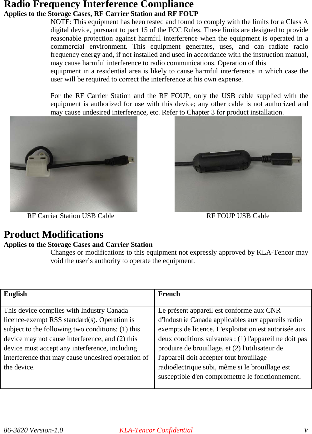
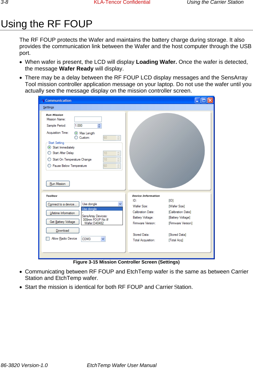
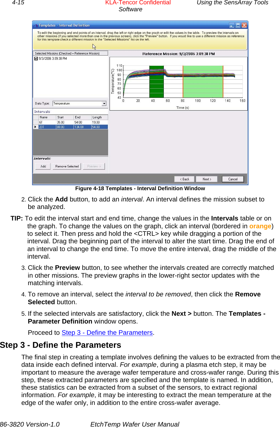
![Using the SensArray Tools Software KLA-Tencor Confidential 4-16 To define template parameters: 1. Click the Add New Parameter button to add a parameter. A new row appears in the Interval Parameters list, with a drop-down list for Interval, Statistic, and Sensor Pattern. Figure 4-19 Templates - Parameter Definition window 2. Select the interval to which the parameter applies. 3. Select the statistic to calculate for that interval. Available options are Mean, 3Sigma, Max, Min, Range, Median, MaxAverage, and MinAverage. 4. Select the sensor pattern, to select the sensors to use in the calculations. Available options are All, None, Outer Ring, Inner Disc, Mask Edge, and [new pattern]. By default, all sensors on the wafer are used. NOTE: When a sensor pattern is selected, a Sensor Pattern window opens. It is possible to edit the selected sensor pattern characteristics or load a different pattern to edit. To create a new pattern, associate a different pattern name with the result. The button options are Select All, Clear All, Save, Save New, and Cancel. 5. Name the template (on the lower-right of the window). 6. Click the Finish button to save the input. A dialog box opens, to confirm template creation. Click the Yes button to confirm. After the template is created, the first Template Wizard window re-opens, where another template can be added. If this task is complete, close the window and start the Create a Signature module from the PlasmaSuite window. 86-3820 Version-1.0 EtchTemp Wafer User Manual](https://usermanual.wiki/KLA/RFWC812A.Users-Manual/User-Guide-2420610-Page-40.png)
![4-31 KLA-Tencor Confidential Using the SensArray Tools Software Profile Comparison. View 2D profiles of multiple missions. SPC (Statistical Process Control) Chart. Tool used to determine whether a manufacturing or business process is in a state of statistical control or not. If the chart indicates that the process being monitored is not in control, the pattern it reveals can help determine the source of variation to be eliminated to bring the process back into control. A control chart is a specific kind of run chart. Recipe. Computer program, rules, specifications, operations, and procedures, which are organized in steps and are performed each time to produce/process a wafer. Used in PlasmaSuite. Each chamber in the fab must have a recipe associated with it. Steady State. Stable condition that does not change over time, or in which change in one direction is continually balanced by change in another. Recipe Step. Single action within a recipe. Sample Rate. Speed of acquisition during data collection. For example, a sample rate of 2 means that data will be collected from all sensors on the wafer every 2 seconds. Tag, Tagging. Set of metadata for a mission. This metadata includes the person who collected the data, the chamber and recipe (or track and flow) on which the mission was run, the date the mission was run, and notes. Scatter Plot. Chart that uses Cartesian coordinates to display values for two variables. Data is displayed as a collection of points, each having one coordinate on the horizontal axis and one on the vertical axis. Template. Defines the regions of interest within a mission run using a specific process (recipe or flow). It also defines the important statistics for each region (such as mean, range, and standard deviation). Identifies critical intervals for a production, monitoring, or diagnostic process (recipe or flow). Sensor. Device that responds to an environmental variable (such as temperature). Sensor Pattern. Select the sensors to be used in calculating template parameters during a mission run. Available options are All, None, Outer Ring, Inner Disc, Mask Edge, and [new pattern]. By default, all sensors on the wafer are used. Track. Enclosed system used to heat, process, and cure semiconductor wafers. USB (Universal Serial Bus). Replaces various kinds of serial and parallel port connectors with one standardized plug and port combination. Connect USB-compliant devices (for example, the provided portable computer), by way of a USB cable connected to the devices’ USB port(s), then power-on the devices. Signature. Allows numbers to be associated with a template, to indicate the expected values for the calculated statistics. For example, if a template for a recipe calculated the mean of a steady-state period, the signature for that template would specify the minimum and maximum values expected for that mean. Wafer. Thin round slice of a semiconductor material from which chips are made. SmartDevice Control Center. Software that allows the user to set up and run missions to gather fab data for analysis. Used with 3rd generation SmartFOUP360ez and SmartBOXez devices. Wafer Carrier. Used to protect wafers during the wafer fabrication. Wafer Fabrication. Series of manufacturing operations that places the circuit or device in and on the wafer. 86-3820 Version-1.0 EtchTemp Wafer User Manual](https://usermanual.wiki/KLA/RFWC812A.Users-Manual/User-Guide-2420610-Page-55.png)