KMART Rear Tine, Gas Tiller Manual L1004250
User Manual: KMART KMART Rear Tine, Gas Tiller Manual KMART Rear Tine, Gas Tiller Owner's Manual, KMART Rear Tine, Gas Tiller installation guides
Open the PDF directly: View PDF ![]() .
.
Page Count: 72
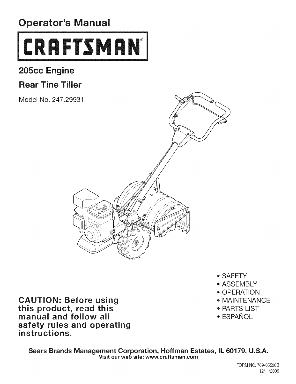
Operator's Manual
I:Rl FI'SlVl N
205cc Engine
Rear Tine Tiller
Model No. 247.29931
CAUTION: Before using
this product, read this
manual and follow aJl
safety rules and operating
instructions.
*SAFETY
*ASSEMBLY
*OPERATION
*MAINTENANCE
*PARTS LIST
*ESPANOL
Sears Brands Management Corporation, Hoffman Estates, IL 60179, U.S.A.
Visit our web site: www.craftsman.com
FORMNO.769-05526B
12/11/2009
WarrantyStatement..................................Pac
Safetyinstructions....................................Pac
SafetyLabels............................................Pac
Assembly..................................................Pac
Operation..................................................Pac
ServiceandMaintenance.........................Pac
Off-SeasonStorage..................................Pac
e2
es3-6
e7
es8-9
es10-17
es18-23
e24
TroubleShooting.......................................Page25
PartsList...................................................Page26-31
LabelMap.................................................Page41
RepairProtectionAgreement...................Page44
Espa_ol.....................................................Page45
ServiceNumbers......................................BackCover
CRAFTSMAN FULLWARRANTY
Whenoperatedand maintainedaccordingto allsuppliedinstructions,if this Craftsmanproductfailsdueto a defectin materialorworkmanship
withintwoyearsfromthe date orpurchase,call 1-800-4-MY-HOME®to arrangefor free repair(or replacementif repairprovesimpossible).
Thiswarrantyappliesfor only90 daysfromthe dateof purchaseif thisproductis everusedfor commercialor rentalpurposes.
ThiswarrantycoversONLYdefectsin materialandworkmanship.Searswill NOTpayfor:
• Expendableitemsthatbecomewornduringnormaluse,includingbut notlimitedto blades,tines,or belts.
Tireor wheelreplacementor repairresultingfromnormalwear,accident,orimproperoperationor maintenance.
Repairsnecessarybecauseof operatorabuse,includingbutnot limitedto damagecausedby impactingobjectsthat bendthe frameor
motorcrankshaft.
Repairsnecessarybecauseof operatornegligence,includingbut not limitedto,electricalandmechanicaldamagecausedby improper
storage,orfailureto maintainthe equipmentaccordingtothe instructionscontainedin theoperator'smanual.
• Repairsnecessarydueto improperfuel mixture,contaminatedor stalefuel.
Normaldeteriorationandwearof the exteriorfinishes,or productlabelreplacement.
Thiswarrantyappliesonly whilethisproductis withinthe UnitedStates.
Thiswarrantygivesyou specificlegalrights,andyou mayalso haveotherrightswhichvaryfromstateto state.
Sears, Roebuck and Co., Hoffman Estates, IL 60179
EngineSeries: 205cc
EngineOilType: SAE30
EngineOilCapacity: 20ounces
Fuel: UnleadedGasoline
SparkPlug: Champion®RC-12YC
SparkPlugGap: .030"
Model Number.................................................................
Serial Number .................................................................
Dateof Purchase.............................................................
Recordthe modelnumber,serialnumber
anddateof purchaseabove
©SearsBrands,LLC 2

Thissymbolpointsout importantsafetyinstructionswhich,if not
followed,couldendangerthe personalsafetyand/orpropertyof
yourselfandothers. Readandfollowall instructionsin thismanual
beforeattemptingto operatethismachine.Failureto complywith
theseinstructionsmayresultin personalinjury.Whenyou seethis
symbol,HEEDITSWARNING!
CALIFORNIA PROPOSITION 65
EngineExhaust,someof itsconstituents,andcertainvehicle
componentscontainoremitchemicalsknownto Stateof California
to causecancerandbirthdefectsorother reproductiveharm.Bat-
tery posts,terminals,andrelatedaccessoriescontainleadand lead
compounds,chemicalsknownto the Stateof Californiato cause
cancerandreproductiveharm.Washhandsafterhandling.
Thismachinewasbuilt to beoperatedaccordingto the safeopera-
tion practicesin thismanual.As withany typeof powerequipment,
carelessnessorerroronthe part of the operatorcan resultin
seriousinjury.Thismachineis capableof amputatingfingers,hands,
toesandfeetandthrowingdebris.Failureto observethe following
safetyinstructionscouldresultin seriousinjuryordeath.
Your Responsibility=Restrict the useof this powermachineto
personswho read,understandandfollowthewarningsand instruc-
tionsin thismanualandon the machine.
SAVETHESEINSTRUCTIONS!
TRAINING
•Read,understand,andfollowall instructionson the machineand
in themanual(s)beforeattemptingto assembleandoperate.
Keepthis manualina safeplacefor futureand regularreference
andfor orderingreplacementparts.
• Readthe Operator'sManualand followallwarningsand safety
instructions.Failureto doso can resultin seriousinjuryto the
operatorand/or bystanders.Forquestions,call 1-800-4MY-HOME.
• Befamiliarwithall controlsandtheir properoperation.Knowhow
to stopthe machineanddisengagethemquickly.
• Neverallowchildrenunder14yearsof ageto operatethis
machine.Children14andover shouldreadandunderstandthe
instructionsandsafeoperationpracticesin thismanualandon
the machineandbe trainedandsupervisedby anadult.
• Neverallowadultsto operatethis machinewithoutproper
instruction.
• Keepbystanders,pets,andchildrenat least75feetfromthe
machinewhile it is in operation.Stopmachineif anyoneenters
the area.
• Neverrunanengineindoorsor ina poorlyventilatedarea.Engine
exhaustcontainscarbonmonoxide,anodorlessanddeadlygas.
PREPARATION
•Thoroughlyinspecttheareawherethe equipmentis to beused.
Removeall rocks,bottles,cans,or otherforeignobjectswhich
could bepickedupor thrownandcausepersonalinjuryor
damageto the machine.
• Alwayswear safetyglassesor safetygogglesduringoperation
andwhile performingan adjustmentor repair,to protectyour
eyes.Thrownobjectswhichricochetcan causeseriousinjuryto
the eyes.
• Wearsturdy,rough-soledworkshoesandclose-fittingslacksand
shirts.Loosefittingclothesor jewelrycan becaughtin movable
parts.Neveroperatethismachineinbarefeetorsandals.
• Beforestarting,checkallboltsandscrewsfor propertightnessto
besurethe machineis insafeworkingcondition.Also,visually
inspectmachinefor any damageat frequentintervals.
• Disengageclutchleversandshift (if provided)into neutral("N")
beforestartingtheengine.
• Neverleavethismachineunattendedwiththe enginerunning.
• Neverattemptto makeanyadjustmentswhilethe engineis
running,exceptwherespecificallyrecommendedinthe operator's
manual.
• Maintainor replacesafetyandinstructionslabels,as necessary.
3
Safe Handling of Gasoline:
Toavoidpersonalinjuryor propertydamageuseextremecare in
handlinggasoline.Gasolineis extremelyflammableandthe vaporsare
explosive.Seriouspersonalinjurycan occurwhengasolineis spilled
onyourselfor yourclotheswhichcan ignite.Washyour skinand
changeclothesimmediately.
• Useonlyan approvedgasolinecontainer.
• Neverfill containersinsidea vehicleor ona truckor trailerbed
witha plasticliner.Alwaysplacecontainersonthe groundaway
fromyour vehiclebeforefilling.
• Whenpractical,removegas-poweredequipmentfromthe truck
ortrailerand refuelitonthe ground.Ifthisis notpossible,then
refuelsuchequipmenton a trailerwitha portablecontainer,rather
thanfroma gasolinedispensernozzle.
• Keepthe nozzleincontactwiththe rimof the fuel tankor
containeropeningat alltimes untilfuelingis complete.Do not use
a nozzlelock-opendevice.
• Extinguishallcigarettes,cigars,pipesandother sourcesof
ignition.
• Neverfuel machineindoors.
• Neverremovegas capor addfuel whilethe engineishot or run-
ning.Allowengineto cool at leasttwo minutesbeforerefueling.
• Neveroverfill fueltank. Fill tankto nomorethan1/2inchbelow
bottomof filler neckto allowspacefor fuel expansion.
• Replacegasolinecapandtightensecurely.
• Ifgasolineisspilled,wipe itoff theengineandequipment.Move
unitto anotherarea.Wait5 minutesbeforestartingthe engine.
• To reducefire hazards,keepmachinefreeof grass, leaves,or
otherdebrisbuild-up.Cleanupoil orfuel spillageand removeany
fuel soakeddebris.
• Neverstorethe machineorfuel containerinsidewherethereis an
openflame,sparkor pilotlightas on awaterheater,spaceheater,
furnace,clothesdryer orothergas appliances.
OPERATION
•Do not puthandsorfeetnear rotatingparts.Contactwiththe
rotatingpartscan amputatehandsand feet.
• Do notoperatemachinewhileunderthe influenceof alcoholor
drugs.
• Neveroperatethismachinewithoutgoodvisibilityor light.Always
be sureof yourfootingandkeepa firmholdonthe handles.
• Keepbystandersawayfromthe machinewhileit isinoperation.
Stopthe machineif anyoneentersthe area.
• Becarefulwhentilling inhardground.Thetines maycatchinthe
groundandpropelthe tillerforward.Ifthis occurs,let goof the
handlebarsanddo not restrainthe machine.
• Exerciseextremecautionwhenoperatingonor crossinggravel
surfaces.Stayalert for hiddenhazardsortraffic. Do notcarry
passengers.
• Neveroperatethe machineat hightransportspeedson hardor
slipperysurfaces.
• Exercisecautionto avoidslippingor falling.
• Lookdownand behindandusecare whenin reverseor pulling
machinetowardsyou.
• Startthe engineaccordingto the instructionsfoundinthis manual
and keepfeetwell awayfromthe tinesat all times.
• Afterstrikingaforeignobjector ifyour machineshouldstart mak-
inganunusualnoiseor vibration,immediatelyshutthe engineoff.
Disconnectthe sparkplugwire,grounditagainstthe engineand
performthe followingsteps:
a. Inspectfor damage.
b. Repairor replaceanydamagedparts.
c. Checkfor anyloose partsandtightento assurecontinued
safeoperation.
• Disengageall clutchlevers(if fitted)and stopenginebeforeyou
leavethe operatingposition(behindthe handles).Waituntil
the tinescometo a completestopbeforeuncloggingthe tines,
makingany adjustments,or inspections.
• Neverrunanengineindoorsorina poorlyventilatedarea.Engine
exhaustcontainscarbonmonoxide,an odorlessanddeadlygas.
• Mufflerandenginebecomehot andcancausea burn.Do not
touch.
• Usecautionwhentillingnearfences,buildingsandunderground
utilities.Rotatingtinescan causepropertydamageor personal
injury.
• Donot overloadmachinecapacityby attemptingto till soil too
deepat too fastof a rate.
• Ifthe machineshouldstart makinganunusualnoiseor vibration,
stopthe engine,disconnectthe sparkplugwire andgroundit
againstthe engine.Inspectthoroughlyfor damage.Repairany
damagebeforestartingandoperating.
• Keepallshields,guards,and safetydevicesinplaceandoperat-
ing properly.
• Neverpick uporcarrymachinewhilethe engineis running.
• Useonly attachmentsandaccessoriesapprovedby the manu-
factureras listedin the PartsListpagesof thisoperator'smanual.
Failureto doso can resultin personalinjury.
• Ifsituationsoccurwhichare notcoveredinthis manual,use care
andgoodjudgement.ContactCustomerSupportat 1-800-4MY-
HOMEfor assistanceandthe nameof thenearestservicedealer
MAINTENANCE & STORAGE
•Keepthe machine,attachmentsandaccessoriesin safeworking
order.
•Allowthe machineto coolat leastfiveminutesbeforestoring.
Nevertamperwithsafetydevices.Checktheirproperoperation
regularly.
•Checkboltsandscrewsfor propertightnessat frequentintervals
to keepthe machineinsafeworkingcondition.Also,visually
inspectmachineforany damage.
• Beforecleaning,repairing,or inspecting,stopthe engineand
makecertainthetinesandall movingpartshavestopped.
Disconnectthe sparkplugwireandgrounditagainstthe engineto
preventunintendedstarting.
4
• Do notchangethe enginegovernorsettingsor over-speedthe
engine.Thegovernorcontrolsthemaximumsafeoperatingspeed
of engine.
Maintainor replacesafetyandinstructionlabels,as necessary.
Followthis manualfor safeloading,unloading,transporting,and
storageof thismachine.
Alwaysreferto theoperator'smanualfor importantdetailsif the
machineis to bestoredforan extendedperiod.
If thefuel tankhasto be drained,do thisoutdoors.
Observeproperdisposallawsandregulationsfor gas,oil, etc.to
protectthe environment.
Accordingto the ConsumerProductsSafetyCommission(CPSC)
andthe U.S.EnvironmentalProtectionAgency(EPA),thisproduct
hasan AverageUsefulLifeof seven(7)years,or 130hoursof
operation.At the endof theAverageUsefulLifehavethe machine
inspectedannuallyby anauthorizedservicedealerto ensurethat
allmechanicalandsafetysystemsareworkingproperlyandnot
wornexcessively.Failureto do so can resultinaccidents,injuries
ordeath.
DO NOT MODIFY ENGINE
Toavoidseriousinjuryordeath,donot modifyenginein anyway.
Tamperingwiththe governorsettingcan leadto a runawayengineand
causeit to operateat unsafespeeds.Nevertamperwithfactorysetting
of enginegovernor.
NOTICE REGARDING EMISSIONS
EngineswhicharecertifiedtocomplywithCaliforniaandfederal
EPAemissionregulationsfor SORE(SmallOff RoadEquipment)are
certifiedto operateon regularunleadedgasoline,and mayinclude
the followingemissioncontrolsystems:EngineModification(EM),
OxidizingCatalyst(CO),SecondaryAirInjection(SAI)and ThreeWay
Catalyst(TWO)if so equipped.
SPARK ARRESTOR
Thismachineis equippedwithan internalcombustionengineand
shouldnotbe usedonor nearanyunimprovedforest-covered,
brushcoveredor grass-coveredlandunlessthe engine'sexhaust
systemis equippedwitha sparkarrestermeetingapplicablelocal or
statelaws(if any)
Ifa sparkarresteris used,it shouldbemaintainedin effectiveworking
orderby theoperator.Inthe Stateof Californiathe aboveis required
bylaw (Section4442of the CaliforniaPublicResourcesCode).Other
statesmayhavesimilarlaws. Federallawsapplyonfederallands.
A sparkarresterfor the muffleris availablethroughyournearestSears
PartsandRepairServiceCenter.
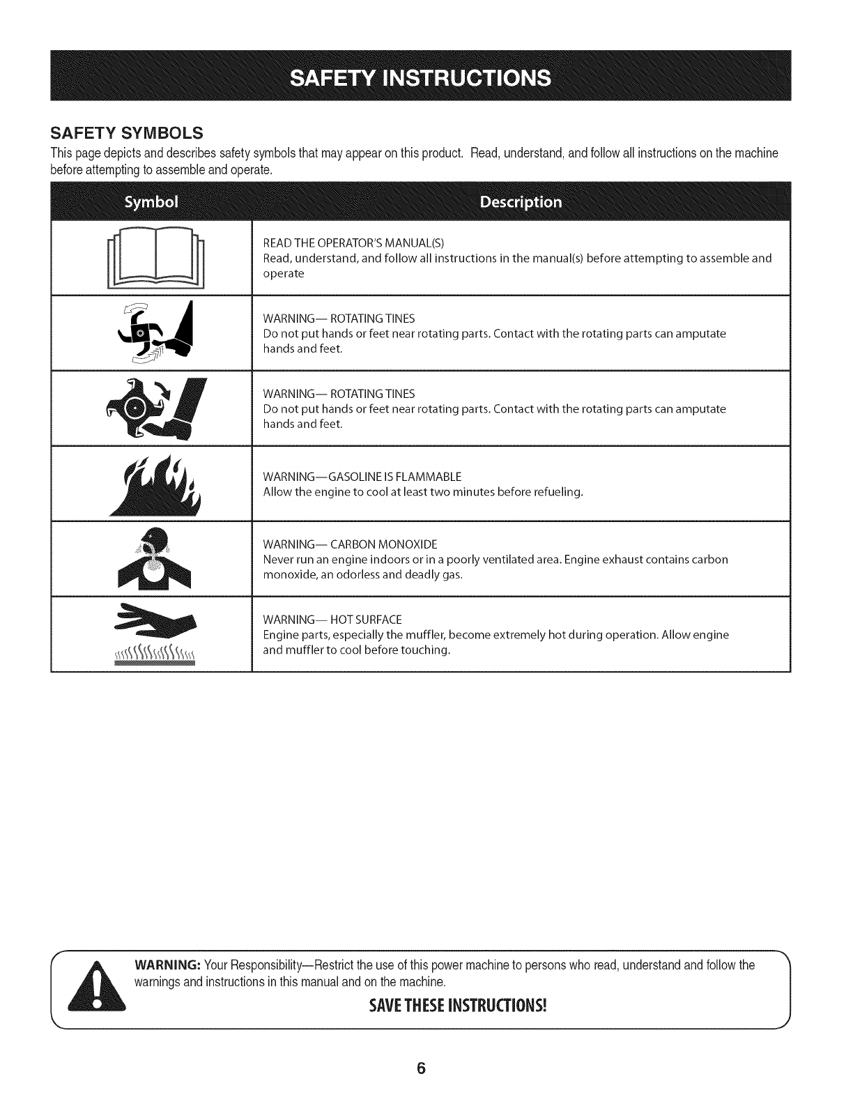
SAFETY SYMBOLS
Thispagedepictsanddescribessafetysymbolsthatmayappearonthisproduct. Read,understand,andfollowall instructionson the machine
beforeattemptingto assembleandoperate.
ii
READ THE OPERATOR'S MANUAL(S)
Read, understand, and follow all instructions in the manual(s) before attempting to assemble and
operate
WARNING-- ROTATING TINES
Do not put hands or feet near rotating parts. Contact with the rotating parts can amputate
hands and feet.
WARNING-- ROTATING TINES
Do not put hands or feet near rotating parts. Contact with the rotating parts can amputate
hands and feet.
WARNING--GASOLINE IS FLAMMABLE
Allow the engine to cool at least two minutes before refueling.
WARNING-- CARBON MONOXIDE
Never run an engine indoors or in a poorly ventilated area. Engine exhaust contains carbon
monoxide, an odorless and deadly gas.
WARNING-- HOT SURFACE
Engine parts, especially the muffler, become extremely hot during operation. Allow engine
and muffler to cool before touching.
WARNING: YourResponsibility--Restrictthe use of thispowermachineto personswho read,understandandfollowthe
warningsand instructionsinthis manualandonthe machine.
SAVETHESEINSTRUCTIONS!
6
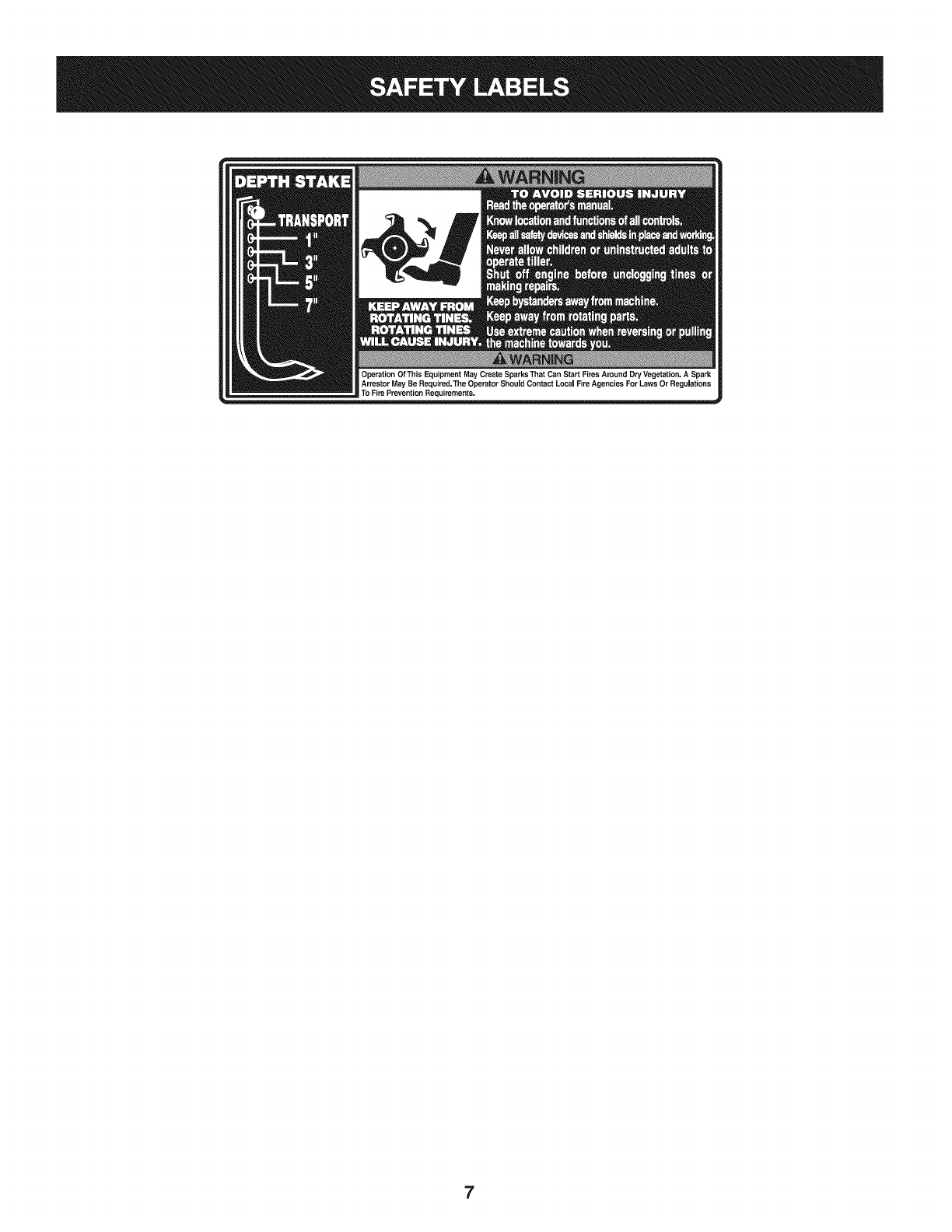
7
IMPORTANT:Thisunit is shippedwithoutgasolineoroil inthe engine.
Becertainto serviceenginewithgasolineandoilas instructedinthe
Operationsectionof this manualbeforeoperatingyourmachine.
NOTE:Referenceto rightand lefthandsideof the Tilleris observed
fromthe operatingposition.
OPENING CARTON
1. Removeall staplesfromaroundthe bottomof the perimeter.
2. Removethe cartonfromthe skid.
3. Removeall looseparts.
4. Removeloosepackingmaterial.
REMOVING UNiT FROM SKiD
1. Thetiller is heavy,do notattemptto removeit fromthe skiduntil
instructedto do so intheseassemblysteps.
2. Checkcartonthoroughlyfor anyotherlooseparts.
LOOSE PARTS IN CARTON
• HandlebarAssembly
• Tiller
• EngineOil
• Operator'sManual
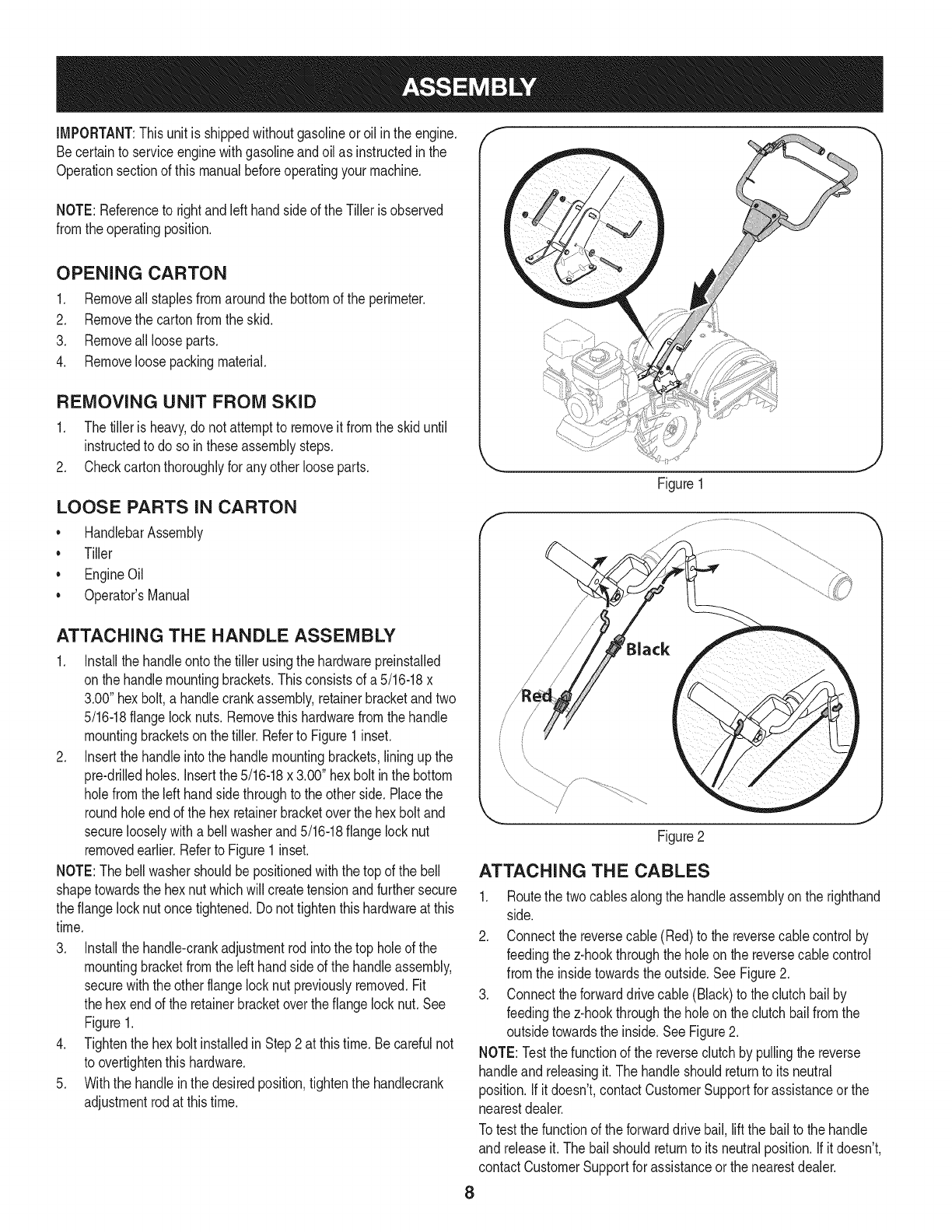
ATTACHING THE HANDLE ASSEMBLY
1. Installthe handleontothetiller usingthe hardwarepreinstalled
onthe handlemountingbrackets.Thisconsistsof a 5/16-18x
3.00"hex bolt,a handlecrankassembly,retainerbracketandtwo
5/16-18flangelocknuts. Removethishardwarefromthe handle
mountingbracketson the tiller.Referto Figure1inset.
2. Insertthe handleintothe handlemountingbrackets,lining upthe
pre-drilledholes.Insertthe5/16-18x 3.00" hexbolt inthe bottom
holefromthe left handside throughto the otherside.Placethe
roundholeendof the hex retainerbracketoverthe hexbolt and
securelooselywitha bellwasherand5/16-18flangelocknut
removedearlier.Referto Figure1inset.
NOTE:Thebellwashershouldbepositionedwiththe top of the bell
shapetowardsthe hexnutwhichwill createtensionandfurthersecure
theflange locknutonce tightened.Donot tightenthishardwareatthis
time.
3. Installthe handle-crankadjustmentrodintothe top holeof the
mountingbracketfromthe lefthandsideof the handleassembly,
securewiththe otherflangelocknut previouslyremoved.Fit
the hexendof the retainerbracketoverthe flangelocknut.See
Figure1.
4. Tightenthe hexbolt installedin Step2 at thistime. Becarefulnot
to overtightenthishardware.
5. Withthe handleinthe desiredposition,tightenthe handlecrank
adjustmentrodat thistime.
Figure1
/
/
/
J
Figure2
ATTACHING THE CABLES
1. Routethe twocablesalongthe handleassemblyon the righthand
side.
2. Connectthe reversecable(Red)to the reversecablecontrolby
feedingthez-hookthroughthe holeon the reversecablecontrol
fromthe insidetowardstheoutside.SeeFigure2.
3. Connecttheforwarddrivecable(Black)to the clutchbailby
feedingthez-hookthroughthe holeon the clutchbailfromthe
outsidetowardsthe inside.SeeFigure2.
NOTE:Testthefunctionof the reverseclutchby pullingthe reverse
handleand releasingit.The handleshouldreturnto its neutral
position.If it doesn't,contactCustomerSupportforassistanceorthe
nearestdealer.
Totest the functionof the forwarddrivebail, liftthe bailto the handle
and releaseit.The bailshouldreturnto itsneutralposition.If it doesn't,
contactCustomerSupportfor assistanceor the nearestdealer.
8
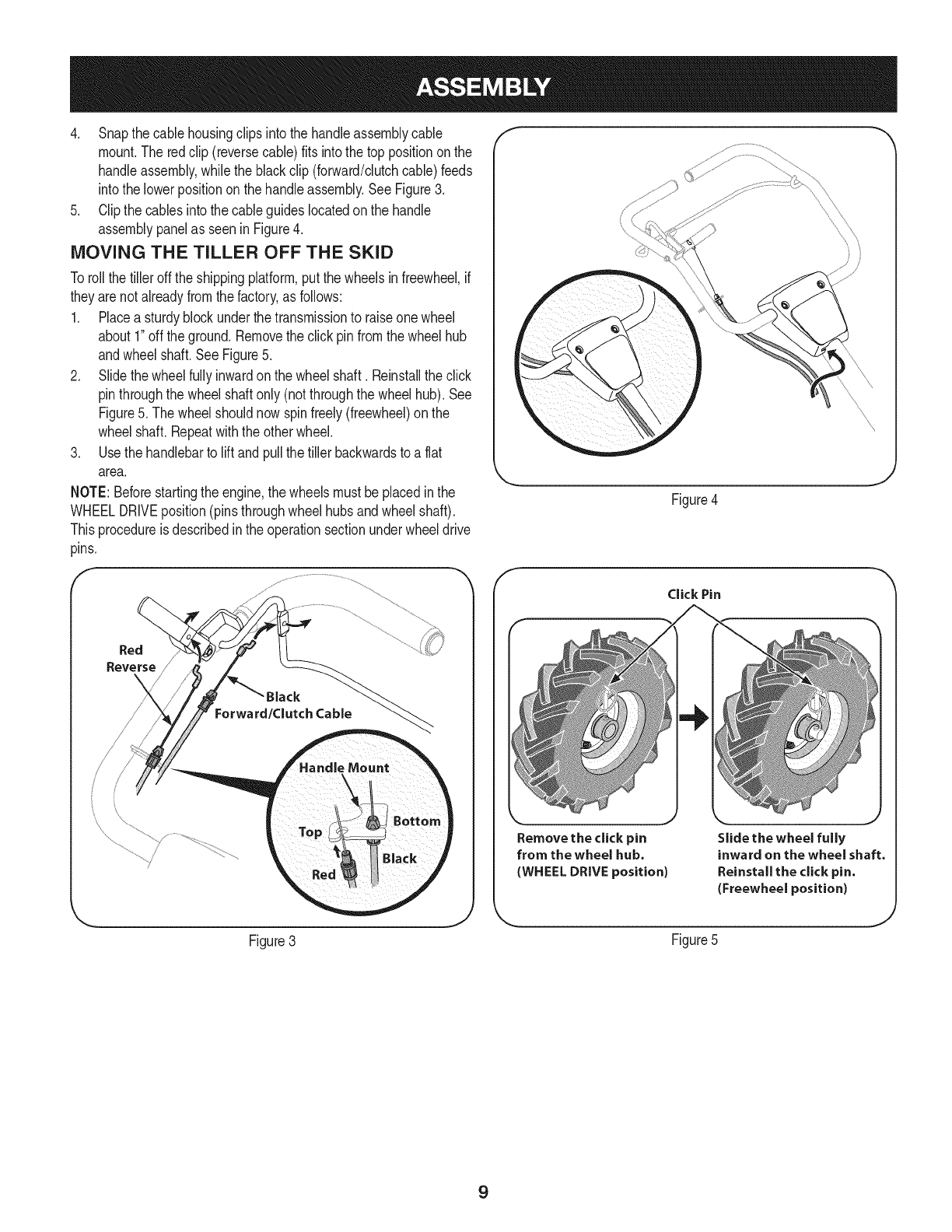
4. Snapthe cablehousingclips intothe handleassemblycable
mount.The redclip (reversecable)fits into thetop positiononthe
handleassembly,whilethe blackclip (forward/clutchcable)feeds
intothe lowerpositiononthe handleassembly.See Figure3.
5. Clipthe cablesintothe cableguideslocatedon the handle
assemblypanelas seenin Figure4.
MOVING THE TILLER OFF THE SKID
Torollthe tiller offthe shippingplatform,putthe wheelsinfreewheel,if
theyarenotalreadyfromthe factory,as follows:
1. Placea sturdyblockunderthe transmissionto raiseonewheel
about1"off theground.Removetheclick pinfromthe wheelhub
andwheelshaft.SeeFigure5.
2. Slidethewheelfullyinwardon the wheelshaft. Reinstallthe click
pinthroughthe wheelshaftonly (notthroughthe wheelhub).See
Figure5. The wheelshouldnowspinfreely(freewheel)on the
wheelshaft.Repeatwiththe otherwheel.
3. Usethe handlebarto liftand pullthetiller backwardsto a flat
area.
NOTE:Beforestartingthe engine,the wheelsmustbe placedinthe
WHEELDRIVEposition(pins throughwheelhubsandwheelshaft).
Thisprocedureis describedinthe operationsectionunderwheeldrive
pins.
f
Red
Reverse
Figure4
f
Click Pin
Remove the click pin
from the wheel hub.
(WHEEL DRIVE position)
Slide the wheel fully
inward on the wheel shaft.
Reinstall the click pin.
(Freewheel position)
Figure3 Figure5
J
9
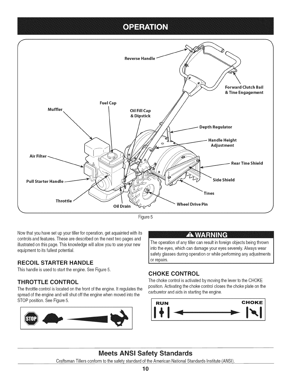
f
Reverse Handle
Fuel Cap
Oil Fill Cap
& Dipstick
Depth Regulator
Forward Clutch Bail
& Tine Engagement
Air
Handle Height
Adjustment
Rear Tine Shield
Pull Starter Handle Side Shield
Throttle
Oil Drain
Tines
Wheel Drive Pin
Figure5
Nowthat youhavesetup yourtillerfor operation,get aquaintedwithits
controlsandfeatures.Thesearedescribedonthe nexttwo pagesand
illustratedon thispage.Thisknowledgewillallowyou to useyour new
equipmentto itsfullestpotential.
RECOIL STARTER HANDLE
Thishandleis usedto startthe engine.See Figure5.
THROTTLE CONTROL
Thethrottlecontrolis locatedon thefrontof theengine.It regulatesthe
spreadof the engineandwill shutoff theenginewhen movedintothe
STOPposition.SeeFigure5.
The operationof anytiller can resultinforeignobjectsbeingthrown
intothe eyes,whichcan damageyoureyesseverely.Alwayswear
safetyglassesduringoperationor whileperforminganyadjustments
or repairs.
CHOKE CONTROL
The chokecontrolis activatedby movingthe leverto the CHOKE
position.Activatingthe chokecontrolclosesthe chokeplateonthe
carburetorandaids instartingthe engine.
RUN CHOKE
Meets ANSi Safety Standards
CraftsmanTillersconformto the safetystandardof the AmericanNationalStandardsInstitute(ANSI).
10
AiR FILTER REAR TJNE SHIELD
Theair filterisa deviceonthe engineair intakethatpreventsdustand The rearfine shieldprotectsthe operatorfromflyingdebriswhilealso
dirt enteringthe engine.SeeFigure5. smoothingoutfreshlytilled soil.See Figure5.
MUFFLER
Engineexhaustexitsthe enginevia the muffler.SeeFigure5.
OIL FILL CAP & DIPSTICK
Engineoil levelcan becheckedand oiladdedthroughtheoil fill. See
Figure5.
NOTE:ThisunitwasshippedWITHOUToil inthe engine.Oilis
includedinthe plasticbag packedwiththe manualinwiththe unit.
Addtheoil as directedin theGas & OilFill Up section.Checkthe oil
levelbeforeeachoperationto ensureadequateoil is inthe engine.
Forfurtherinstructions,referto the stepsinthe EngineMaintenance
sectionof thismanual.
REVERSE HANDLE
The ReverseHandlecontrolsthe reversedriveof the wheelsandthe
tines.SeeFigure5.
FORWARD CLUTCH BAiL & TINE ENGAGE-
MENT
Theforwardclutchbailcontrolstheengagementof theforwarddriveof
the wheelsandtines.SeeFigure5.
SIDE SHIELD
The side shieldis usedto maintaincleareven rowsandmaybe
adjustedto oneof fivedifferentpositions.SeeFigure5.
TINES
Yourfiller'stinesarea seriesof hoesarrangedon a revolvingpower-
drivenshaft.SeeFigure5.
WHEEL DRIVE PiNS
Eachwheelis equippedwitha wheeldriveclickpinthat securesthe
wheelto the wheelshaft.The wheelscan bepositionedineithera
WHEELDRIVEora FREEWHEELmode.SeeFigure5.
OiL DRAIN
Removingtheoil drainplugwilldrainthe oilfromthe engine.See
Figure5.
DEPTH REGULATOR LEVER
Thislevercontrolsthe tillingdepthof the tines.Pullthe leverbackand
slideit upor downto engagethe notchedheight.See Figure5.
HANDLEBAR HEIGHT ADJUSTMENT
Thehandlebarheightis adjustableto threedifferentsettings.In
general,adjustthe handlebarsso theyareat waistlevelwhenthe tines
are3-4" inthe ground.SeeFigure5.
11

GAS AND OiL FILL-UP f "_
Oil (one bottle shipped with unit)
FirstTimeUse
1. Removeoilfill dipstick.
2. Withthe tilleron levelground,usea funnelto emptyentire
contentsofoil bottleprovidedintothe engine.
3. Replaceoilfill dipstickandtighten.
Subsequent Uses
Only usehighqualitydetergentoil ratedwithAPIserviceclassification
SF,SG, SH,SJor higher.Selectthe oil's SAEviscositygradeaccord-
ingto the expectedoperatingtemperature.Followthe chartbelow.
oc
Althoughmulti-viscosityoils (5W30,10W30,etc.)improvestarting
in coldweather,theywill resultinincreasedoil consumptionwhen
usedabove32°RCheckyourengineoil levelmorefrequentlyto avoid
possibleenginedamagefromrunninglowon oil.
1. Checkthe oillevelmakingcertainnotto rubthe dipstickalong
the insidewallsof the oil fill tube.Thiswould resultina false
dipstickreading.Wipedipstickcleanwithcloth. Replacedipstick
into theoil fillerneck, butdo not screwit in. Removeandcheck
oil level.Refillto FULLmarkon dipstick,if necessary.Capacityis
approximately20oz.Overfillingwill causethe engineto smoke
profuselyandwill resultin poorengineperformance.
2. Replaceoilfill dipstickandtighten.
3. Keepoil levelat FULL.Runningthe enginewithtoo littleoilcan
resultinpermanentenginedamage.
Transmission/Gear Oil
FirstTimeUse
1. Withthe tilleron levelground,pullthe DepthRegulatorLever
backandthenall thewayup untilthe lowestnotchin the leveris
engaged.SeeFigure6.
2. Removethe oilfill plugfromthe transmissionhousingcoverand
locatethe maindrive shaftsituatedinsidethe housing.
See Figure7.
3. The gearoil levelis correctif the gearoilis approximatelyhalfway
up theside of the maindriveshaft.
4. If the oillevelis low,referto the transmissiongearoilunderthe
MaintenanceSection.
Depth Regulater Lever
12
Figure6
\
Figure7
J
Useextremecarewhen handlinggasoline.Gasolineis extremely
flammableandthevaporsare explosive.Neverfuel machineindoors
or whiletheengineis hot or running.Extinguishcigarettes,cigars,
pipes,andothersourcesof ignition.
Gasoline
1. Removefuel capfromthe fueltank.
2. Makesurethe containerfromwhichyou will pourthe gasolineis
cleanandfree fromrustorforeignparticles.Neverusegasoline
that maybe stalefromlongperiodsof storageinits container.
Gasolinethathas beensittingforany periodlongerthan four
weeksshouldbeconsideredstale.
3. Fillfuel tankwithclean,fresh,unleadedregulargasolineonly.Do
not usegasolinecontainingMETHANOL.Replacefuel cap.
Alcoholblendedfuels(calledgasoholorusingethanolormethanol)
canattractmoisturewhichleadstoseparationandformationofacids
duringstorage.Acidicgascandamagethefuelsystemofanengine
whileinstorage.
Toavoidengineproblems,thefuelsystemshouldbeemptiedbefore
storagefor30daysorlonger.Drainthegastank,starttheengine
andletitrununtilthefuellinesandcarburetorareempty.Usefresh
fuelnextseason.SeeSTORAGEInstructionsforadditionalinforma-
tion.
Neveruseengineorcarburetorcleanerproductsinthefueltankor
permanentdamagemayoccur.
NOTE:Checkthefuellevelperiodicallytoavoidrunningoutof
gasolinewhileoperatingthetiller.
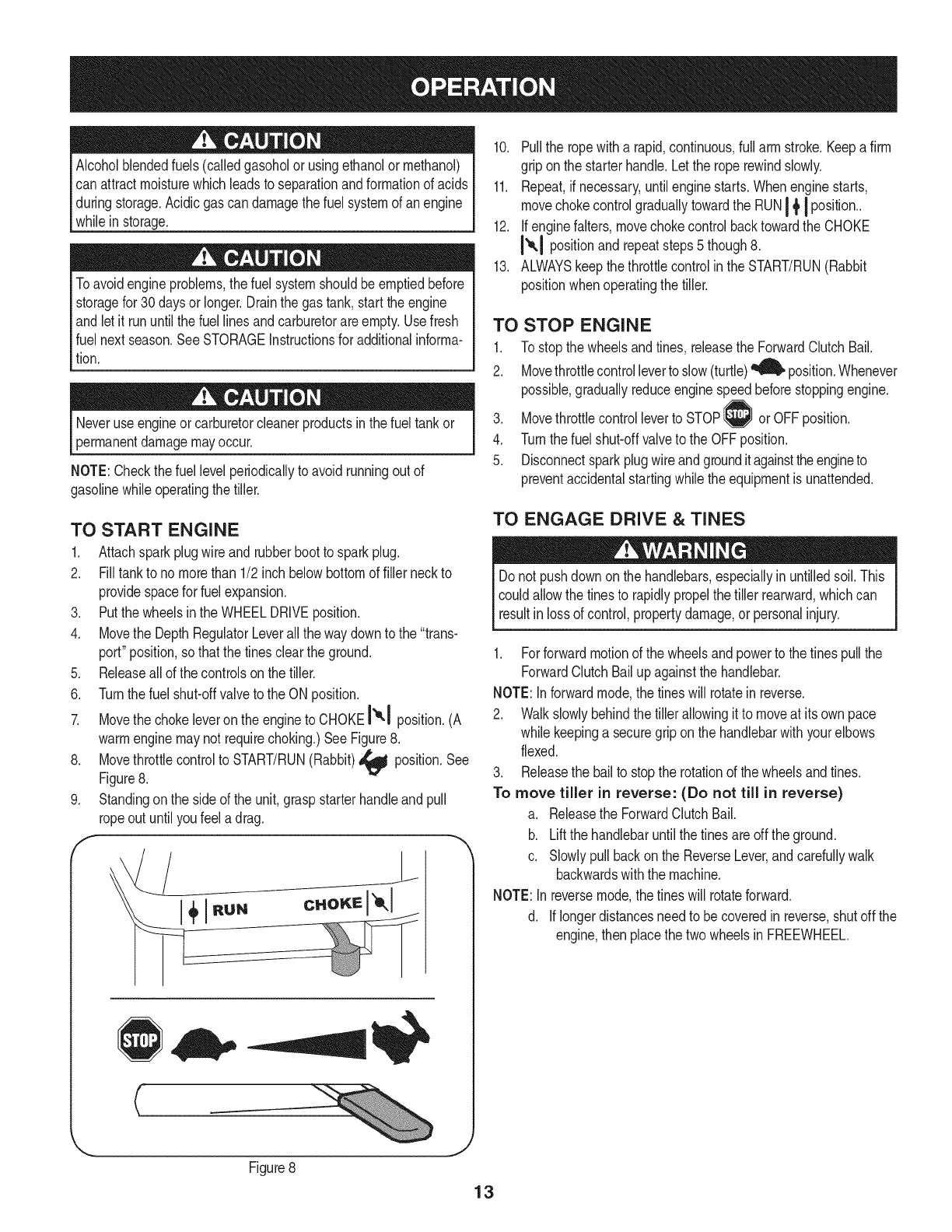
TO START ENGINE
1. Attachsparkplugwire andrubberbootto sparkplug.
2. Filltankto nomorethan 1/2 inch belowbottomof filler neckto
providespacefor fuelexpansion.
3. Putthewheelsinthe WHEELDRIVEposition.
4. Movethe DepthRegulatorLeverallthe waydownto the "trans-
port" position,so thatthe tinesclearthe ground.
5. Releaseallof the controlson the tiller.
6. Turnthefuel shut-offvalveto the ON position.
7. Movethe chokeleveron theengineto CHOKEI'_1 position.(A
warmenginemaynot requirechoking.)SeeFigure8.
8. Movethrottlecontrolto START/RUN(Rabbit)_ position.See
Figure8.
9. Standingonthe sideof the unit,graspstarterhandleandpull
ropeout untilyoufeel a drag.
f
__jL
10. Pullthe ropewitha rapid,continuous,full arm stroke.Keepafirm
gripon the starterhandle.Letthe roperewindslowly.
11. Repeat,if necessary,untilenginestarts.Whenenginestarts,
movechokecontrolgraduallytowardthe RUNI _'I position..
12. Ifenginefalters,movechokecontrolbacktowardthe CHOKE
I_,1 positionandrepeatsteps5 though8.
13. ALWAYSkeepthe throttlecontrolin theSTART/RUN(Rabbit
positionwhenoperatingthe tiller.
TO
1.
2.
.
4.
5.
STOP ENGINE
To stopthe wheelsandtines, releasethe ForwardClutchBail.
Movethrottlecontrolleverto slow(turtle)_ position.Whenever
possible,graduallyreduceenginespeedbeforestoppingengine.
Movethrottlecontrolleverto STOP or OFFposition.
Turnthefuel shut-offvalveto the OFFposition.
Disconnectsparkplugwireandgroundit againsttheengineto
preventaccidentalstartingwhilethe equipmentis unattended.
TO ENGAGE DRIVE &TINES
Do not pushdown onthe handlebars,especiallyin untilledsoil.This
couldallowthe tinesto rapidlypropelthetiller rearward,whichcan
resut n ossof contro, propertydamage,or persona njury.
1. Forforwardmotionof the wheelsandpowerto the tinespullthe
ForwardClutchBailupagainstthe handlebar.
NOTE:Inforwardmode,the tineswill rotatein reverse.
2. Walkslowlybehindthetiller allowingit to moveat itsown pace
while keepinga securegrip onthe handlebarwithyourelbows
flexed.
3. Releasethe bailto stopthe rotationof the wheelsandtines.
To move tiller in reverse: (Do not till in reverse)
a. Releasethe ForwardClutchBail.
b. Liftthe handlebaruntilthe tinesareoffthe ground.
c. Slowlypullbackon the ReverseLever,andcarefullywalk
backwardswiththe machine.
NOTE:In reversemode,the tineswill rotateforward.
d. Iflongerdistancesneedto becoveredinreverse,shutoff the
engine,then placethe two wheelsinFREEWHEEL.
J
Figure8
13
TURNING THE TILLER
1. Practiceturningthetillerinalevel,openarea.Beverycarefulto keep
yourfeetandlegsawayfromthe tines.
2. Tobegina turn,lift the handlebarsuntilthe tinesareout of the
groundandthe engineandtinesare balancedoverthewheels.
3. Withthetillerbalanced,pushsidewaysonthehandlebartosteerinthe
directionof the turn.Afterturning,slowlylowerthe tinesintothe
soilto resumetilling.
Becertainsparkplugwireis disconnectedandgroundedagainstthe
enginewhen performinganyadjustments.
SETTING THE DEPTH
Tillingdepthis controlledby the depthstakewhichcan beadjustedto
fivedifferentsettings.Adjustthe side shieldsas youadjustthedepth
stake.
• Whenusingthe tillerfor thefirst time,use the secondadjustment
holefromthe top (1"of tillingdepth).
• Whenbreakingupsod andfor shallowcultivation,usethe setting
whichgives1"of tillingdepth (secondholefromthe top).Place
the sideshieldsintheirlowestposition.
• Forfurtherdepth,raisethe depthstakeandside shieldsandalso
makeoneor twomorepassesoverthe area.
• Whentillingloosesoil,thedepth stakemaybe raisedto its
highestposition(usebottomadjustmenthole)to give the deepest
tillingdepth.Raisethe sideshieldsto their highestposition.
• Totransporttiller,lowerthe depthstake(usetop adjustment
hole).
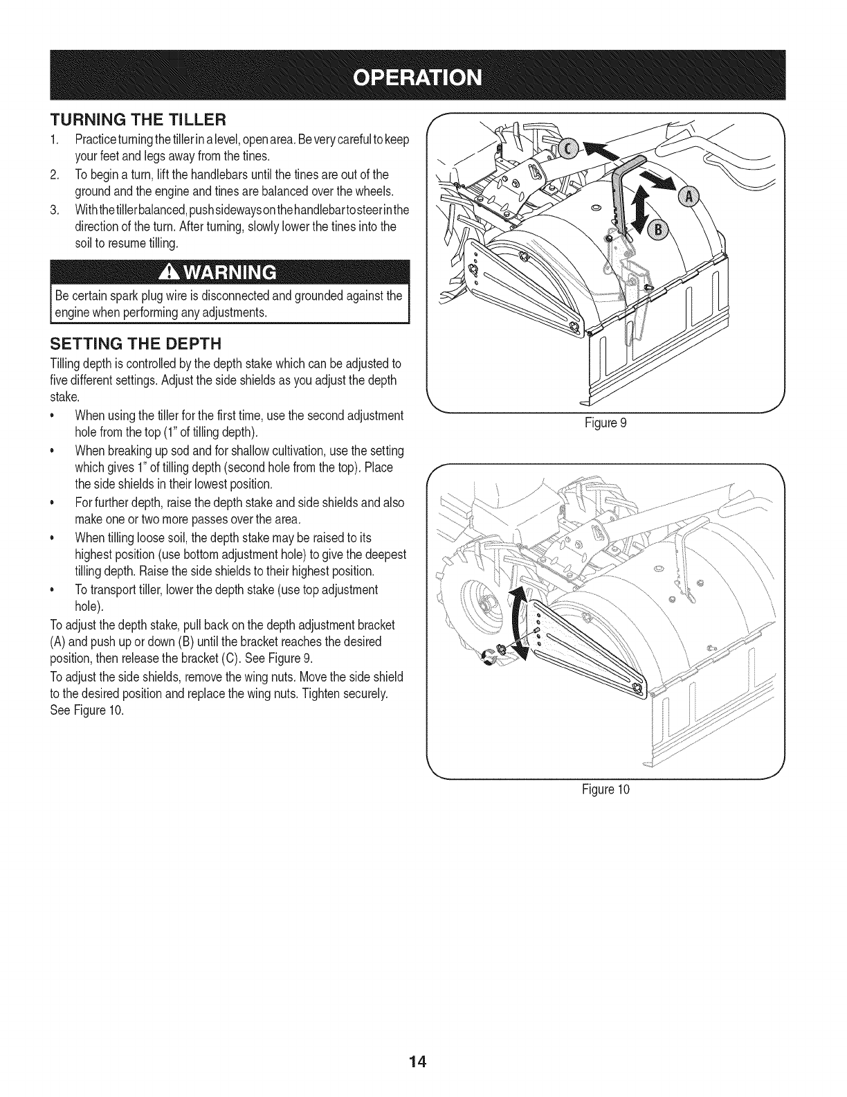
Toadjustthe depthstake,pullbackonthe depthadjustmentbracket
(A)andpush upordown (B)until the bracketreachesthe desired
position,then releasethe bracket(C). SeeFigure9.
Toadjustthe side shields,removethe wing nuts.Movethe side shield
to the desiredpositionandreplacethe wing nuts.Tightensecurely.
SeeFigure10.
Figure9
Figure10
J
14
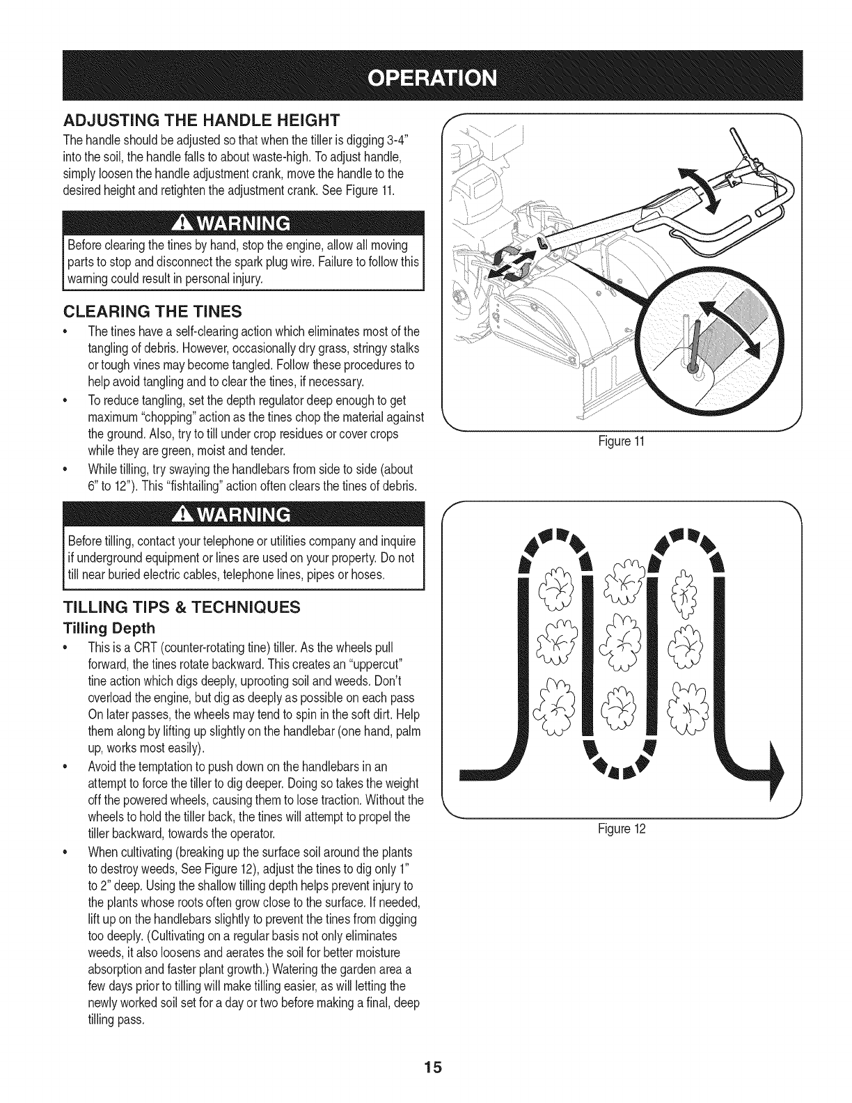
ADJUSTING THE HANDLE HEIGHT
Thehandleshouldbeadjustedso thatwhenthe tillerisdigging3-4"
intothe soil,the handlefallsto aboutwaste-high.Toadjusthandle,
simplyloosenthe handleadjustmentcrank,movethe handleto the
desiredheightandretightenthe adjustmentcrank.SeeFigure11.
Beforeclearingthe tinesby hand,stopthe engine,allowall moving
partsto stopanddisconnectthe sparkplugwire.Failureto followthis
warningcould resultin personalinjury.
CLEARING THE TINES
* Thetineshavea self-clearingactionwhicheliminatesmostof the
tanglingof debris.However,occasionallydry grass,stringystalks
ortoughvinesmaybecometangled.Followtheseproceduresto
helpavoidtanglingandto clearthe tines,if necessary.
* Toreducetangling,setthe depth regulatordeepenoughto get
maximum"chopping"actionas the tineschopthe materialagainst
the ground.Also,try to till undercrop residuesorcovercrops
whiletheyaregreen,moistand tender.
* Whiletilling,try swayingthe handlebarsfromsideto side (about
6"to 12").This"fishtailing"actionoftenclearsthe tinesof debris.
Beforetilling,contactyourtelephoneor utilitiescompanyandinquire
ifundergroundequipmentor linesareusedon yourproperty.Do not
till nearburiedelectriccables,telephonelines,pipesor hoses.
TILLING TiPS & TECHNIQUES
Tilling Depth
* Thisis a CRT(counter-rotatingtine)tiller.As the wheelspull
forward,the tinesrotatebackward.Thiscreatesan"uppercut"
tineactionwhichdigs deeply,uprootingsoilandweeds.Don't
overloadthe engine,butdig as deeplyas possibleon eachpass
Onlater passes,the wheelsmaytendto spin inthe soft dirt.Help
themalongby liftingupslightlyonthe handlebar(onehand,palm
up,worksmosteasily).
* Avoidthe temptationto pushdownon the handlebarsinan
attemptto forcethe tiller to digdeeper.Doingso takestheweight
offthe poweredwheels,causingthemto losetraction.Withoutthe
wheelsto holdthe tillerback,the tineswillattemptto propelthe
tillerbackward,towardsthe operator.
* Whencultivating(breakingupthe surfacesoil aroundthe plants
to destroyweeds,SeeFigure12),adjustthe tinesto dig only 1"
to 2" deep.Usingthe shallowtillingdepth helpspreventinjuryto
the plantswhoserootsoftengrowcloseto the surface.If needed,
lift uponthe handlebarsslightlyto preventthe tinesfromdigging
too deeply.(Cultivatingona regularbasisnotonly eliminates
weeds,it alsoloosensandaeratesthesoil for bettermoisture
absorptionandfasterplantgrowth.)Wateringthe gardenareaa
fewdayspriorto tillingwill maketilling easier,as will lettingthe
newlyworkedsoil setfor aday ortwo beforemakinga final,deep
tillingpass.
Figure11
Figure12
15
Choosing the Correct Wheel & Tine Speeds
Withexperience,youwill findthe tillingdepthandtilling speed
combinationthatisbestfor yourgarden.Setthe enginethrottleleverat
a speedto givethe engineadequatepowerandyetallowitto operate
at the slowestpossiblespeeduntilyou haveachievedthe maximum
tillingdepthyoudesire.Fasterenginespeedsmaybedesirable
whenmakingfinalpassesthroughthe seedbedorwhencultivating.
Selectionof the correctenginespeed,inrelationto the tillingdepth,
willensurea sufficientpowerlevelto dothe jobwithoutcausingthe
engineto labor.
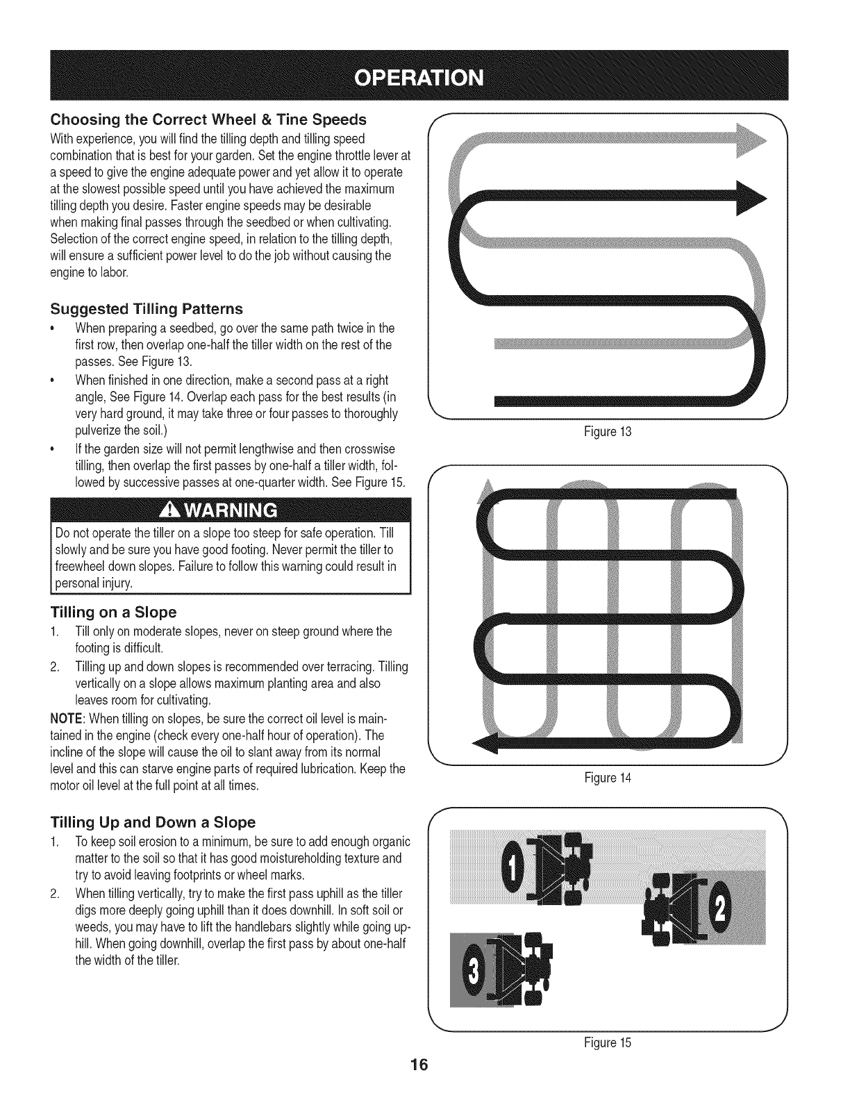
Suggested Tilling Patterns
•Whenpreparinga seedbed,gooverthe samepathtwice inthe
first row,thenoverlapone-halfthetiller widthonthe restof the
passes.SeeFigure13.
•Whenfinishedinonedirection,makea secondpassat a right
angle,SeeFigure14.Overlapeach passfor the bestresults(in
veryhardground,itmaytakethreeorfour passesto thoroughly
pulverizethe soil.)
•Ifthe gardensizewill not permitlengthwiseandthen crosswise
tilling,then overlapthefirst passesbyone-halfa tillerwidth,fol-
lowedby successivepassesat one-quarterwidth.See Figure15.
Do notoperatethe tilleron a slopetoo steepfor safeoperation.Till
slowlyandbe sureyou havegoodfooting.Neverpermitthetiller to
freewheeldownslopes.Failureto followthis warningcouldresultin
[persona njury.
Tilling on a Slope
1. Till onlyon moderateslopes,neveronsteepgroundwherethe
footingisdifficult.
2. Tillingupanddownslopesisrecommendedoverterracing.Tilling
verticallyona slopeallowsmaximumplantingareaandalso
leavesroomfor cultivating.
NOTE:Whentilling onslopes,besurethe correctoil levelismain-
tainedinthe engine(checkeveryone-halfhourof operation).The
inclineof the slopewillcausetheoil to slantawayfromitsnormal
levelandthiscan starveenginepartsof requiredlubrication.Keepthe
motoroil levelat thefull pointat alltimes.
Tilling Up and Down a Slope
1. Tokeepsoil erosionto a minimum,be sureto addenoughorganic
matterto thesoil so thatit hasgoodmoistureholdingtextureand
try to avoidleavingfootprintsorwheel marks.
2. Whentillingvertically,try to makethe first passuphillas the tiller
digs moredeeplygoinguphillthan itdoesdownhill.In soft soilor
weeds,you mayhaveto lift the handlebarsslightlywhilegoingup-
hill.Whengoingdownhill,overlapthe first passbyaboutone-half
thewidthof the tiller.
f
,.. j
Figure13
T
mm _
Figure14
f
16
Figure15

Terrace Gardening
1. Tocreatea terrace,startat the top of the slopeandworkdown Go
backandforthacrossthe first row.See Figure16.
2. EachsucceedingIowerterraceisstartedbywalkingbelowtheterrace
youare preparing.Foraddedstabilityof the tiller,alwayskeepthe
uphillwheelinthe soft,newlytilled soil.Do nottill the last 12"or
moreof the downhilloutsideedgeof eachterrace.Thisuntilled
striphelpspreventthe terracesfrombreakingapartandwashing
downhill.Italso providesa walkingpathbetweenthe rows.
Loading & Unloading the Tiller
Loadingandunloadingthe tillerinto avehicleis potentiallyhazard-
ous anddoingso is not recommendedunlessabsolutelynecessary,
as thiscould resultin personalinjuryor propertydamage.
If youmustloador unloadthe tiller,followthe guidelinesgiven below:
• Beforeloadingor unloadingthe tiller,stopthe engine,waitforall
partsto stopmoving,disconnectthe sparkplugwireandlet the
engineandmufflercool.
Putthe wheelsin freewheelby puttingthe clickpins throughthe
wheelshaftonly (notthroughthe wheelhub).
Thetiller is too heavyandbulkyto be safelyliftedby oneperson.
Twoor morepeopleshouldsharethe load.
• Usesturdyrampsandmanually-- withtheengineshutoff -- roll
the tillerintoand outof the vehicle.Twoor morepeopleare
neededto dothis.
• The rampsmustbestrongenoughto supportthe combined
weightof the tillerandany handlers.The rampsshouldprovide
goodtractionto preventslipping;theyshouldalso havesiderails
to guidethe tiller alongthe ramps;andtheyshouldhavea locking
deviceto securethemto the vehicle.
Thehandlersshouldwearsturdyfootwearthatwill helpto prevent
slipping.
Positionthe loadingvehicleso thatthe rampangleis as flat
as possible(thelessinclineto the ramp,the better).Turnthe
vehicle'sengineoff andapplythe parkingbrake.
• Whengoingup the ramps,standinthe normaloperatingposition
andpushthe tilleraheadof you. Haveapersonat eachside to
turnthe wheels.
Whengoingdownthe ramps,walkbackwardwiththe tiller
followingyou.Keepalert for anyobstaclesbehindyou. Positiona
personat each wheelto controlthe speedof thetiller.Nevergo
downthe rampstiller-first,as the tiller couldtip forward.
• Placewoodenblocksonthe downhillside of thewheelsif you
needto stopthe tiller fromrollingdownthe ramp.Also,use the
blocksto temporarilykeepthe tillerin placeonthe ramps(if
necessary),andto chockthe wheelsin placeafterthe tilleris in
the vehicle.
Afterloadingthe tiller,preventit from rollingbyengagingthe
wheelsinthe WHEELDRIVEposition.Chockthe wheelswith
blocksandsecurelytie thetiller down.
O, ,O
O
I_ REPEAT
.... J
Figure16
17
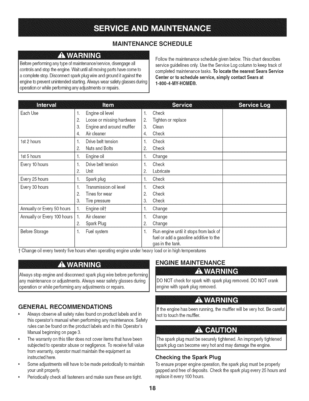
MAINTENANCE SCHEDULE
Beforeperforminganytypeof maintenance/service,disengageall
controlsandstoptheengine.Waituntilallmovingpartshavecometo
acompletestop.Disconnectsparkplugwireandgrounditagainstthe
enginetopreventunintendedstarting.Alwayswearsafetyglassesduring
operationor whileperforminganyadjustmentsor repairs.
Followthe maintenanceschedulegivenbelow.Thischartdescribes
serviceguidelinesonly.Usethe ServiceLogcolumnto keeptrackof
completedmaintenancetasks.To locate the nearest Sears Service
Centeror to scheduleservice,simplycontactSears at
1-800-4-MY-HOME®.
EachUse
1st2 hours
1st5 hours
Every10hours
Every25 hours
Every30 hours
Annuallyor Every50 hours
Annuallyor Every100hours
BeforeStorage
1. Engineoil level
2. Looseor missinghardware
3. Engineandaroundmuffler
4. Air cleaner
1. Drivebelt tension
2. NutsandBolts
1. Engineoil
1. Drivebelt tension
2. Unit
1. Sparkplug
1. Transmissionoil level
2. Tinesfor wear
3. Tire pressure
1. Engineoi11-
1. Air cleaner
2. SparkPlug
1. Fuelsystem
1. Check
2. Tightenorreplace
3. Clean
4. Check
1. Check
2. Check
1. Change
1. Check
2. Lubricate
1. Check
1. Check
2. Check
3. Check
1. Change
1. Change
2. Change
1. Runengineuntilit stopsf_m lackof
fuel oradda gasolineadditiveto the
gas inthe tank.
Changeoileverytwentyfivehourswhenoperatingengineunderheavyloadorin hightemperatures
Alwaysstopengineanddisconnectsparkplugwirebeforeperforming
lany maintenanceor adjustments.Alwayswearsafetyglassesduring
[operationorwhile performingany adjustmentsor repairs.
ENGINE MAINTENANCE
DO NOTcheckfor sparkwithsparkplugremoved.DO NOTcrank
enginewithsparkplug removed.
GENERAL RECOMMENDATIONS
•Alwaysobserveallsafetyrulesfoundonproductlabelsandin
thisoperator'smanualwhenperformingany maintenance.Safety
rulescan befoundonthe productlabelsandin thisOperator's
Manualbeginningon page3.
• Thewarrantyon thistillerdoes notcoveritemsthathavebeen
subjectedto operatorabuseor negligence.Toreceivefull value
fromwarranty,operatormust maintainthe equipmentas
instructedhere.
• Someadjustmentswillhaveto be madeperiodicallyto maintain
yourunit properly.
• Periodicallycheckall fastenersand makesurethesearetight.
Ifthe enginehas beenrunning,the mufflerwill beveryhot. Becareful
notto touchthe muffler.
Thesparkplugmustbesecurelytightened.Animproperlytightened
sparkplugcan becomeveryhot andmaydamagethe engine.
Checking the Spark Plug
Toensureproperengineoperation,the sparkplugmustbeproperly
gappedandfree of deposits.Checkthe sparkplugevery25hoursand
replaceitevery100hours.
18
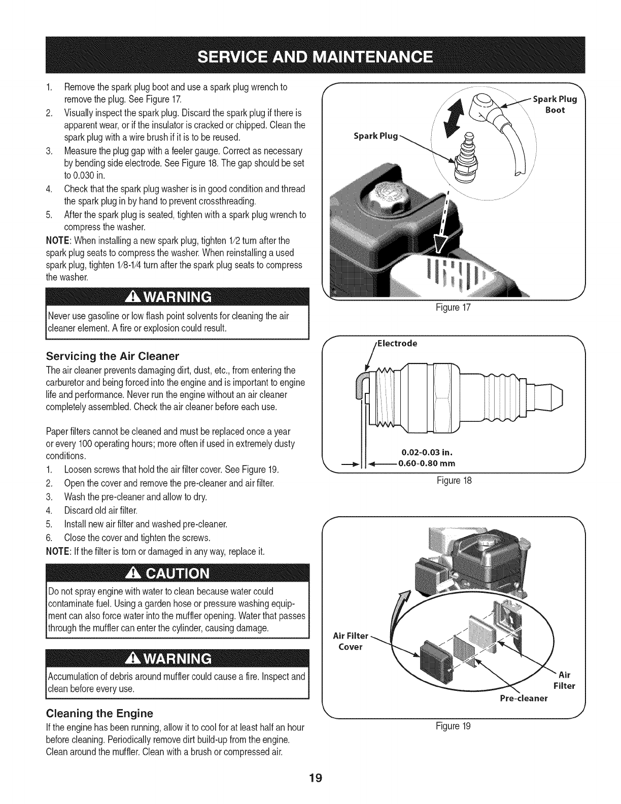
1. Removethesparkplugbootanduse a sparkplugwrenchto
removethe plug.See Figure17.
2. Visuallyinspectthe sparkplug.Discardthe sparkplugif thereis
apparentwear,orif the insulatoris crackedor chipped.Cleanthe
sparkplugwitha wirebrush if it is to be reused.
3. Measurethe pluggapwitha feelergauge.Correctas necessary
by bendingsideelectrode.SeeFigure18.The gapshouldbeset
to 0.030in.
4. Checkthatthe sparkplugwasheris ingoodconditionandthread
the sparkplugin by handto preventcrossthreading.
5. Afterthesparkplugis seated,tightenwitha sparkplugwrenchto
compressthe washer.
NOTE:Wheninstallinga newsparkplug,tighten1/2turn afterthe
sparkplugseatsto compressthe washer.Whenreinstallinga used
sparkplug,tighten1/8-1/4turnafterthe sparkplugseatsto compress
the washer.
Neverusegasolineorlow flashpointsolventsfor cleaningthe air
c eanereement. A f re orexpos oncou d resut.
Servicing the Air Cleaner
Theair cleanerpreventsdamagingdirt, dust,etc.,fromenteringthe
carburetorand beingforcedintothe engineandis importantto engine
life andperformance.Neverrunthe enginewithoutan aircleaner
completelyassembled.Checkthe aircleanerbeforeeach use.
Paperfilterscannotbecleanedandmustbe replacedonce a year
orevery 100operatinghours;moreoftenif usedin extremelydusty
conditions.
1. Loosenscrewsthatholdthe airfiltercover.SeeFigure19.
2. Openthe coverand removethe pre-cleanerandairfilter.
3. Washthe pre-cleanerandallowto dry.
4. Discardold airfilter.
5. Installnewairfilterandwashedpre-cleaner.
6. Closethe coverandtightenthe screws.
NOTE:Ifthe filteris torn ordamagedin anyway,replaceit.
Donot sprayenginewithwaterto clean becausewatercould
contaminatefuel. Usinga gardenhoseorpressurewashingequip-
mentcanalso forcewaterintothe muffleropening.Waterthat passes
throughthe mufflercanenterthe cylinder,causingdamage.
Accumulationof debrisaroundmufflercouldcausea fire.Inspectand
cleanbeforeeveryuse.
Cleaning the Engine
If theenginehasbeenrunning,allowit to coolfor at leasthalfan hour
beforecleaning.Periodicallyremovedirt build-upfromtheengine.
Cleanaroundthe muffler.Cleanwitha brushor compressedair.
Boot
Figure17
,Electrode
0.02-0.03 in.
===_1_====0.60=0.80 mm
Figure18
J
E
Air Filter
Cover
Figure19
Pre+cleaner
Filter
J
19
Check Engine Oil
1. Checkoil beforeeachuse.Stopengineandwaitseveralminutes
beforecheckingoil level.Withthe tilleron levelground,the oil
mustbeto FULLmarkon dipstick.
2. Removeoil fill dipstickandwipe cleanwithcloth.
3. Replacedipstickintothe oilfiller neck,but do not screwitin.
Removeandcheckoil level.Levelshouldbeat FULLmark.
4. If needed,addoil slowly- recheck.Do not overfill.
5. Wipedipstickclean,replacebut donot tighten.Removeand
checkoil level.Oillevelshouldbeat FULLlineondipstick.
6. Replaceandtightendipstickfirmlybeforestartingengine.
DO NOTuse non-detergentoilor 2-strokeengineoil. Itcould shorten
the engine'sservicelife.
Change Engine Oil
•SAE30 is recommendedfor general,all temperatureuse.When
addingoilto theengine,referto viscositychartinthe operation
section.Usea4-stroke,oran equivalenthighdetergent,premium
qualitymotoroil certifiedto meetor exceedU.S.automobile
manufacturer'srequirementsfor serviceclassificationSF,SG, SH,
SJ or higher.MotoroilsclassifiedSF,SG, SH,SJwill showthis
designationon the container.
• Changeengineoil afterthefirst fiveto eight hoursof operation,
andeveryfifty hoursoreveryseasonthereafter.Changeoil every
twentyfivehourswhenoperatingengineunderheavyloadorin
hightemperatures.
Figure20
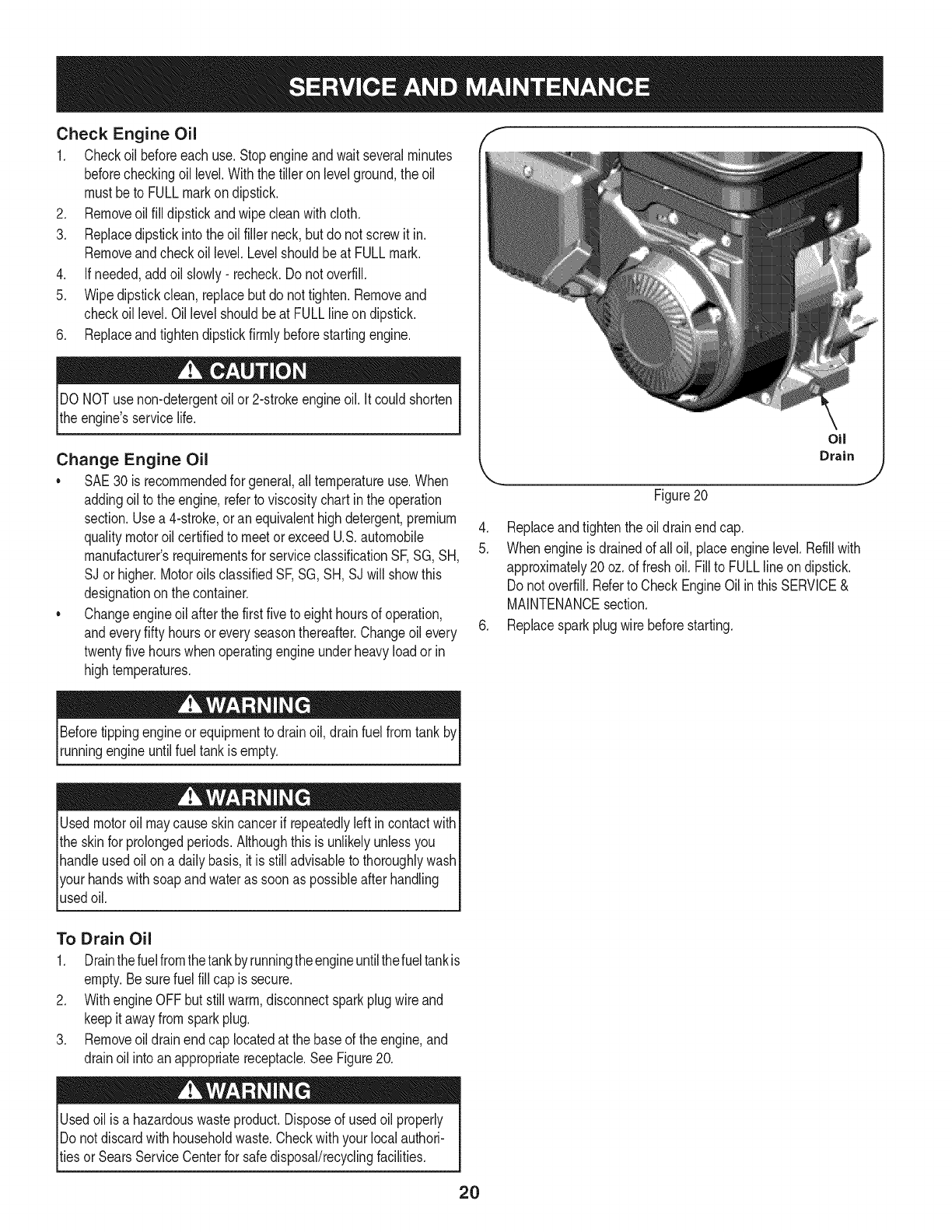
4. Replaceandtightenthe oildrainendcap.
5. Whenengineisdrainedof all oil, placeenginelevel.Refillwith
approximately20oz.of freshoil. Fillto FULLlineondipstick.
Donot overfill.Referto CheckEngineOil inthis SERVICE&
MAINTENANCEsection.
6. Replacesparkplugwire beforestarting.
Beforetippingengineor equipmentto drainoil, drainfuel fromtank by
runningengineuntilfuel tankisempty.
Usedmotoroil maycauseskincancerifrepeatedlyleftincontactwith
the skinfor prolongedperiods.Althoughthis isunlikelyunlessyou
handleusedoil ona daily basis,itis stilladvisableto thoroughlywash
yourhandswithsoapandwateras soonas possibleafter handling
usedoil.
To Drain Oil
1. Drainthefuelfromthetankby runningtheengineuntilthefueltankis
empty.Besurefuel fill cap issecure.
2. WithengineOFFbutstillwarm,disconnectsparkplugwire and
keepitawayfromsparkplug.
3. Removeoil drainendcap locatedat the baseof the engine,and
drainoil into anappropriatereceptacle.SeeFigure20.
Usedoilisa hazardouswasteproduct.Disposeof usedoil properly
IDonot discardwithhouseholdwaste.Checkwithyourlocalauthori-
_tiesor SearsServiceCenterfor safedisposal/recyclingfacilities.
2O
Check Transmission Gear Oil
Checkthetransmissiongearoilafterevery30 hoursof operation
orwheneveryou noticeanyoil leak.Operatingthe tiller whenthe
transmissionis lowon oilcan resultin severedamage.
ToCheckthe TransmissionGearOil Level:
1. Checkthegearoil levelwhenthetransmissionis cool.Gearoil
will expandinwarmoperatingtemperaturesandthis expansion
will providean incorrectoil levelreading.
2. Withthetiller on levelground,pullthe DepthRegulatorLeverall
the wayup.
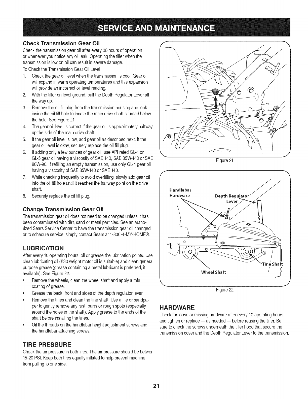
3. Removetheoil fill plugfromthetransmissionhousingand look
insidethe oilfill holeto locatethemaindrive shaftsituatedbelow
the hole.SeeFigure21.
4. Thegearoil levelis correctif the gearoilis approximatelyhalfway
upthe side of the maindriveshaft.
5. If thegearoil levelis low,add gearoil as describednext.Ifthe
gearoillevelis okay,securelyreplacethe oil fill plug.
6. If addingonlya fewouncesof gearoil, useAPI ratedGb4 or
Gb5 gearoil havinga viscosityof SAE 140,SAE85W-140or SAE
80W-90.Ifrefillinganemptytransmission,useonly Gb4 gearoil
havinga viscositydSAE85W-140or SAE140.
7. Whilecheckingfrequentlyto avoidoverfilling,slowlyaddgearoil
intothe oilfill holeuntilit reachesthe halfwaypointon the drive
shaft.
8. Securelyreplacetheoil fill plug.
Change Transmission Gear Oil
Thetransmissiongearoildoes not needto be changedunlessit has
beencontaminatedwithdirt, sandor metalparticles.Seeanautho-
rizedSearsServiceCenterto havethetransmissiongearoil changed
orto scheduleservice,simplycontactSearsat 1-800-4-MY-HOME®.
LUBRICATION
Afterevery10operatinghours,oilor greasethe lubricationpoints.Use
cleanlubricatingoil (#30weightmotoroil is suitable)andcleangeneral
purposegrease(greasecontaininga metallubricantis preferred,if
available).SeeFigure22.
• Removethewheels,clean thewheelshaft andapplya thin
coatingof grease.
• Greasethe back,frontandsidesof the depth regulatorlever.
• Removethetinesandcleanthe fine shaft.Usea file or sandpa-
perto gentlyremoveany rust,burrsor roughspots(especially
aroundthe holesinthe shaft).Applygreaseto the endsof the
shaftbeforeinstallingthe tines.
• Oilthe threadsonthe handlebarheightadjustmentscrewsand
the handlebarattachingscrews.
\
Figure21
Handlebar
Hardware Depth Reg_
Wheel Shaft
Figure22
Tine Shaft
J
HARDWARE
Checkfor looseor missinghardwareafterevery10operatinghours
andtightenor replace= as needed-- beforereusingthe tiller.Be
sureto checkthe screwsunderneaththe tiller hoodthat securethe
transmissioncoverandthe DepthRegulatorLeverto the transmission.
TIRE PRESSURE
Checktheair pressurein bothtires.The airpressureshouldbe betwen
15-20PSi. Keepbothtiresequallyinflatedto helppreventmachine
frompullingto oneside.
21
Beforeperformingany typeof maintenanceonthe machine,waitfor
all partsto stopmovinganddisconnectthe sparkplugwire. Failure
to followthis instructioncouldresultinpersonalinjuryor property
damage.
BELT REPLACEMENT
Ifthe drive beltor reversebeltneedsto be replaced,it is bestto
replacebothbeltsat the sametime.Useonlya factoryauthorized
beltas an "over-the-counter"beltmaynot performsatisfactorily.
The procedurerequiresaveragemechanicalabilityandcommonly
availabletools.
To replacethe DriveandReversebelts,followthesesteps:
1. Makesurethe tiller is ona flat surface,withthe engineturned
offandthe sparkplugwireunpluggedandgroundedto prevent
unintendedfiringof the engine.
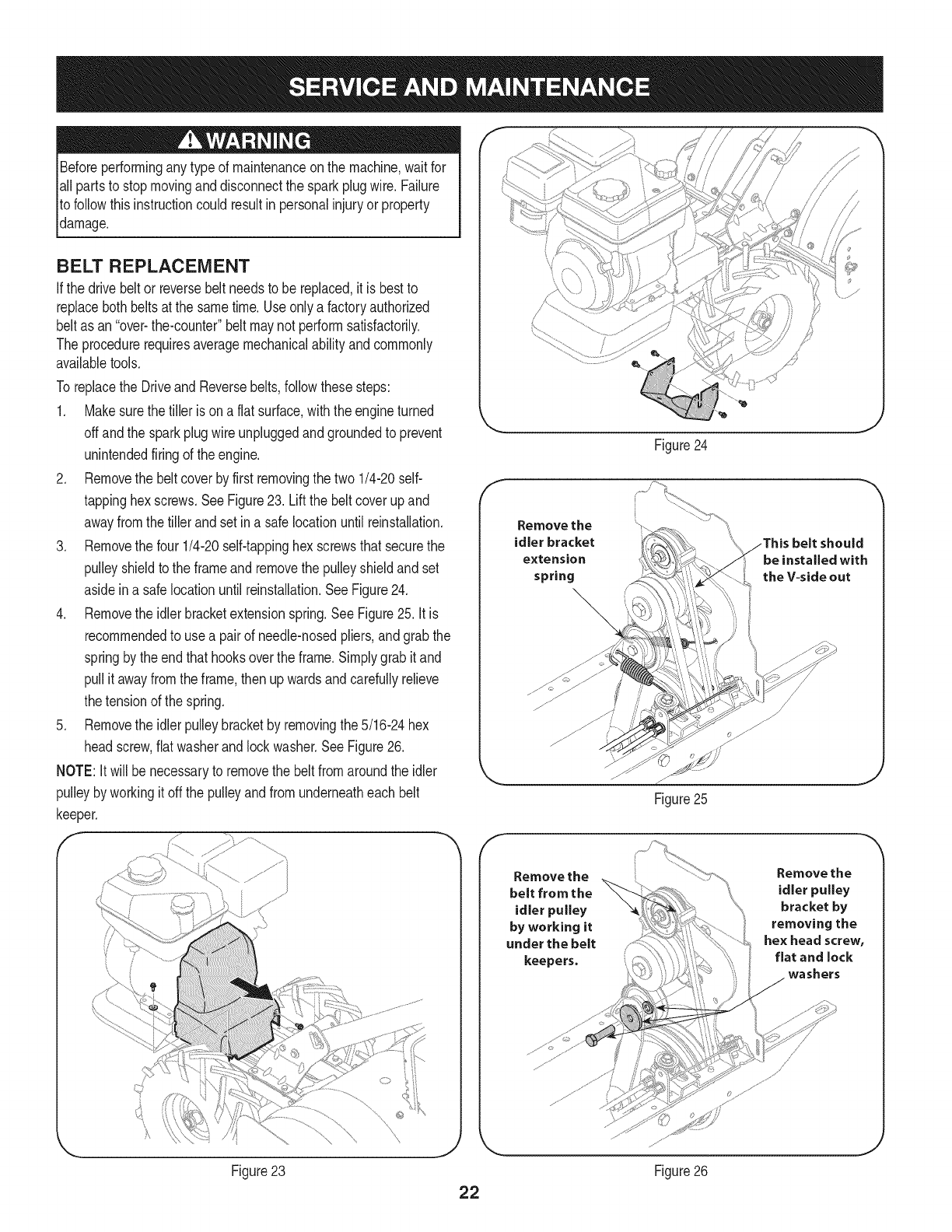
2. Removethe beltcoverby first removingthe two1/4-20self-
tappinghexscrews.SeeFigure23. Liftthe beltcoverupand
awayfromthetiller andsetin a safelocationuntilreinstallation.
3. Removethe four 1/4-20self-tappinghexscrewsthatsecurethe
pulleyshieldtothe frameandremovethe pulleyshieldandset
asideina safelocationuntil reinstallation.SeeFigure24.
4. Removethe idlerbracketextensionspring.See Figure25. It is
recommendedto use a pairof needle-nosedpliers,andgrabthe
springby theendthat hooksoverthe frame.Simplygrabit and
pullit awayfromthe frame,thenupwardsandcarefullyrelieve
thetensionof the spring.
5. Removethe idlerpulleybracketby removingthe 5/16-24hex
headscrew,flatwasherandlockwasher.SeeFigure26.
NOTE:It willbe necessaryto removethe beltfromaroundthe idler
pulleybyworkingit offthe pulleyandfromunderneatheach belt
keeper.
F
Figure23
Figure24
Remove the
idler bracket
extension
spring
Remove the
belt from the
idler pulley
by working it
under the belt
keepers,
Figure25
Remove the
idler pulley
bracket by
removing the
hex head screw,
flat and lock
washers
Figure26

6. Removethehexboltssecuringthetransmissiondrivepulley,then
removethepulleyalongwiththetwobelts.SeeFigure27.
7. Replacetheoldbeltswiththenewbeltsinthe sameorderthey
wereremoved.The longerbelt (1916658)belongscloserto the
engine(V-sideout), withthe shorterbelt(1916657)positioned
closerto the tines.
8. Reinstallthe transmissiondrive pulleywiththe new belts.
9. Reassemblethe tiller inthe reverseorderinwhichitwasdisas-
sembled.
iMPORTANT:Whenreinstallingthe beltcover,be sureto engage
the bailandholditso thatthe drivebelt istightbeforeattemptingto
reinstallthe beltcover.Thiswill enablethe beltto fall underthebelt
keepingmechanismbuiltintothe beltcover.Failureto do so could
damagethe beltand/or belt cover.
TINES
Thetineswill wearwithuseand shouldbe inspectedat the beginning
of eachtilling seasonandafterevery30 operatinghours.Thetines
can bereplaced.Refertothe PartsListsectionof thismanualfor part
numbers.
Tine inspection
Withuse,the tineswill becomeshorter,narrowerandpointed.Badly
worntineswill resultina lossof tilling depth,and reducedeffective-
nesswhenchoppingupandturningunderorganicmatter.
Removing/Installing a Tine Assembly
1. Removethefine shieldendcoversand sideshieldsby removing
the threewingnutsoneach sidethatsecurethem.
2. A fineassemblyconsistsof a lefthandfineanda righthandtine.
NOTE:Thefine assemblymovesina counter-rotatingmotionwith
the sharpedgesof the tinespositionedto enterthe soil firstwhen
counter-rotating.Notethis positionof thetinesfor reinstallationof the
newtine assemblies.
3. Toremovea tine assembly,simplyremovethe cotterpin securing
the clevispin.SeeFigure28.
4. Removetheclevispinand slidethe assemblyto the outsideof
the unitandoff of the tine shaft.
5. Beforereinstallingthe fineassembly,inspectthe fine shaftfor
rust, roughspotsor burrs.Lightlyfile or sand,as needed.Applya
thincoatof greaseto the shaft.
6. Installeachfineassemblyso thatthecutting (sharp)edgeof the
tineswillenterthe soil firstwhenthe tiller movesforward.Keep
in mindthatthesetinesarecounter-rotating,so securethe fine
assemblyto the fine shaftusingthe clevispinandcotterpin.
V-sideout -_
Remove.e*boJt emovepu.ey
............................................;: .......................................be ts
/
Figure27
f
Cotter Pin
Figure28
J
23
Neverstoretiller withfuel in tankindoorsor in poorlyventilatedareasI
wherefuel fumesmayreachanopenflame,spark,or pilotlightas on
a furnace,waterheater,c othesdryer,orgas app ance. 1
Neverleaveengineunattendedwhileit is running.
PREPARING THE ENGINE
Enginesstoredbetween30and 90daysneedto betreatedwitha
gasolinestabilizerandenginesstoredover90daysneedto bedrained
of fuel to preventdeteriorationandgumfromforminginfuel systemor
on essentialcarburetorparts.Ifthe gasolineinyourenginedeterio-
ratesduringstorage,you mayneedto havethecarburetor,andother
fuel systemcomponents,servicedor replaced.
1. Removeallfuel fromtankby runningengineuntilit stopsfrom
lackof fuel.
2. Changethe oil. SeeChangeEngineOil inSERVICEAND
MAINTENANCEsection.
3. Removesparkplugand pourabouta 1/2ounceof engineoilinto
the cylinder.Replacesparkplugandcrankit slowlyto distribute
oil.
4. Cleandebrisfromaroundtheengineandthe muffler.Touchup
any damagedpaint,andcoatotherareasthatmayrustwitha light
filmof oil.
5. Storein a clean,dry andwellventilatedareaawayfromany ap-
pliancethatoperateswitha flameorpilot light,suchas a furnace,
waterheater,orclothesdryer.Alsoavoidany areawitha spark
producingelectricmotor,orwherepowertoolsare operated.
6. Ifpossible,also avoidstorageareaswithhighhumidity,because
that promotesrustandcorrosion.
7. Keeptheenginelevelinstorage.Tiltingcan causefuel or oil
leakage.
PREPARING THE TILLER
Whenthe tillerwon't be usedfor an extendedperiod,prepareit for
storageas follows:
1. Cleanthe tillerandengine.
2. Followthe lubricationrecommendationsandcheckfor looseparts
and hardware.
3. Storethe tiller ina clean,dry area.
4. Neverstorethe tillerwithfuel inthe fuel tankinan enclosedarea
wheregas fumescould reachan openflameor spark,or where
ignitionsourcesare present(spaceheaters,hot waterheaters,
furnaces,etc.).
24
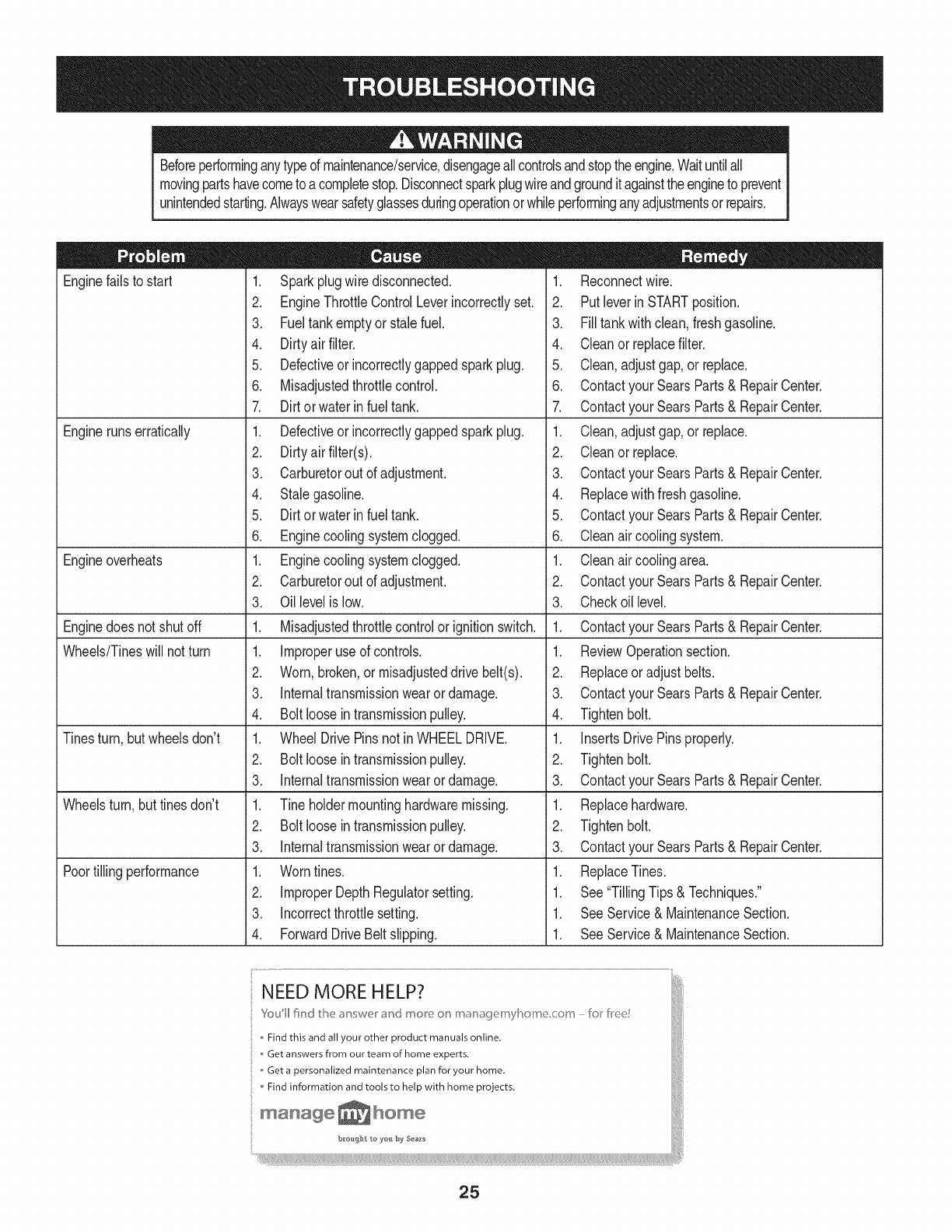
Beforeperforminganytypedmaintenance/service,disengageallcontrolsandstoptheengine.Waituntilall
movingpartshavecometoacompletestop.Disconnectsparkplugwireandgroundit againsttheengineto prevent
unintendedstarting.Alwayswearsafetyglassesduringoperationorwhileperforminganyadjustmentsorrepairs.
Enginefailsto start
Enginerunserratically
Engineoverheats
Enginedoesnot shutoff
Wheels/Tineswill not turn
Tinesturn, butwheelsdon't
Wheelsturn,buttinesdon't
Poortillingperformance
1. Sparkplugwire disconnected.
2. EngineThrottleControlLeverincorrectlyset.
3. Fueltankemptyor stalefuel.
4. Dirtyair filter.
5. Defectiveor incorrectlygappedsparkplug.
6. Misadjustedthrottlecontrol.
7. Dirtorwaterin fuel tank.
1. Defectiveor incorrectlygappedsparkplug.
2. Dirtyair filter(s).
3. Carburetorout of adjustment.
4. Stalegasoline.
5. Dirtorwater infuel tank.
6. Enginecoolingsystemclogged.
1. Enginecoolingsystemclogged.
2. Carburetorout of adjustment.
3. Oillevelis low.
1. Misadjustedthrottlecontrolorignition switch.
1. Improperuse of controls.
2. Worn,broken,or misadjusteddrive belt(s).
3. Internaltransmissionwearor damage.
4. Bolt looseintransmissionpulley.
1. WheelDrivePinsnot inWHEELDRIVE.
2. Bolt looseintransmissionpulley.
3. Internaltransmissionwearor damage.
1. Tineholdermountinghardwaremissing.
2. Bolt looseintransmissionpulley.
3. Internaltransmissionwearor damage.
1. Worntines.
2. ImproperDepthRegulatorsetting.
3. Incorrectthrottlesetting.
4. ForwardDriveBeltslipping.
1. Reconnectwire.
2. Putleverin STARTposition.
3. Filltankwithclean,freshgasoline.
4. Cleanor replacefilter.
5. Clean,adjustgap,or replace.
6. Contactyour SearsParts& RepairCenter.
7. Contactyour SearsParts& RepairCenter.
1. Clean,adjustgap,or replace.
2. Cleanor replace.
3. Contactyour SearsParts& RepairCenter.
4. Replacewithfreshgasoline.
5. Contactyour SearsParts& RepairCenter.
6. Cleanair coolingsystem.
1. Cleanair coolingarea.
2. Contactyour SearsParts& RepairCenter.
3. Checkoil level.
1. Contactyour SearsParts& RepairCenter.
1. ReviewOperationsection.
2. Replaceor adjustbelts.
3. Contactyour SearsParts& RepairCenter.
4. Tightenbolt.
1. InsertsDrivePinsproperly.
2. Tightenbolt.
3. Contactyour SearsParts& RepairCenter.
1. Replacehardware.
2. Tightenbolt.
3. Contactyour SearsParts& RepairCenter.
1. ReplaceTines.
1. See"TillingTips& Techniques."
1. SeeService& MaintenanceSection.
1. SeeService& MaintenanceSection.
NEED MORE HELP?
Find this and all your other product manuals online,
Get answers from our team of home experts, j
Get a personalized maintenance plan for your home, [
Find information and tools to help with home projects.
manage home
25
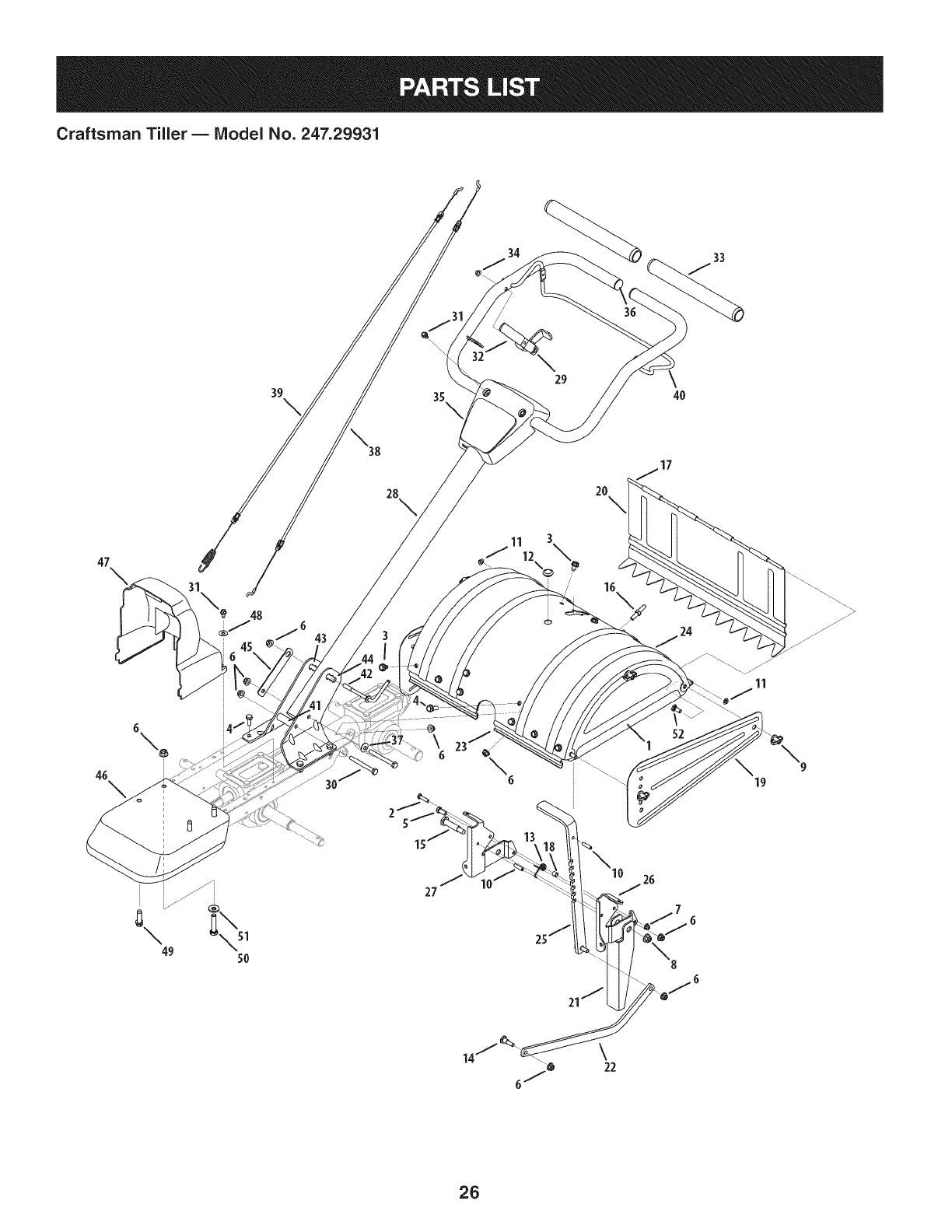
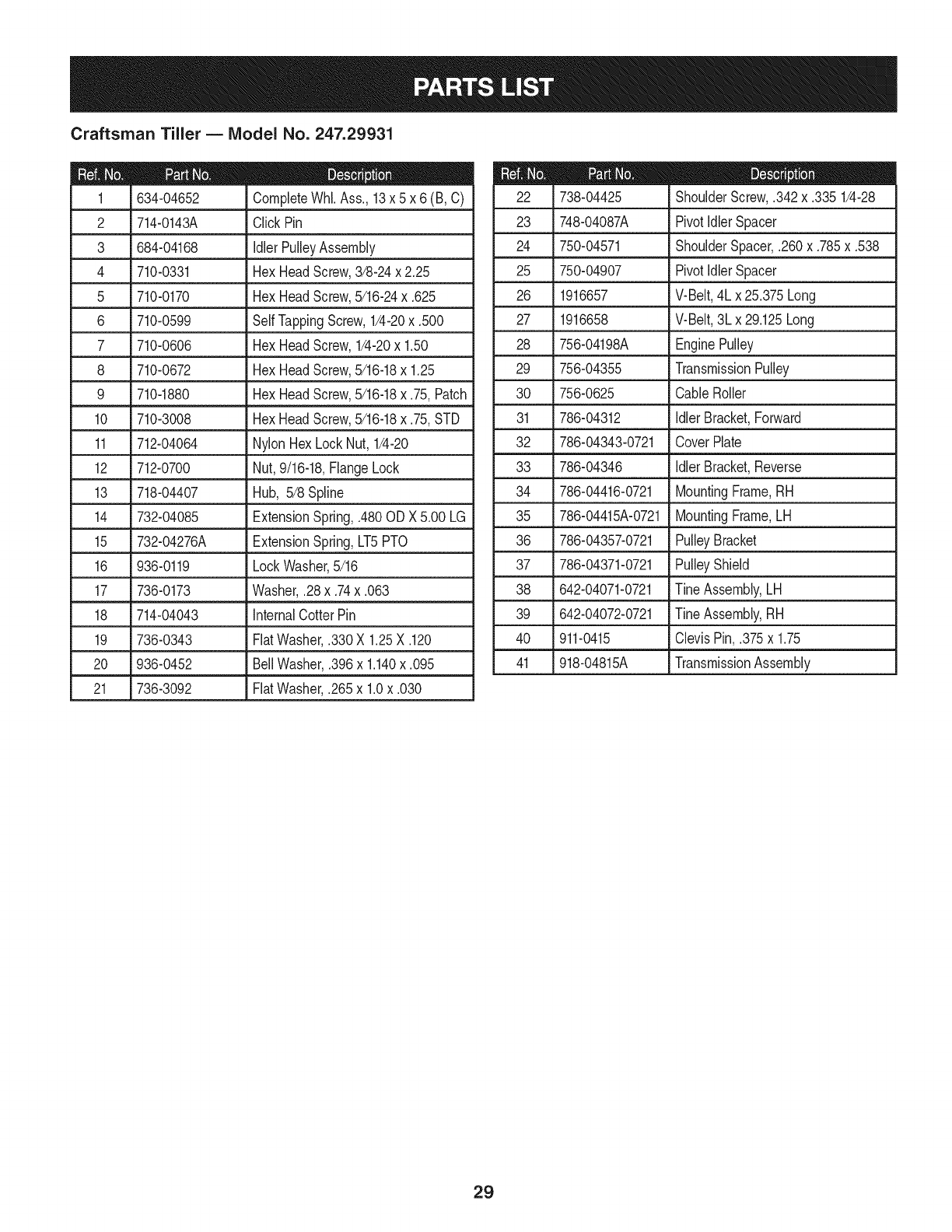
Craftsman Tiller BModel No. 247.29931
29 \4O
6\o \
2O
\
\
11
19
j J>
27
14 \22
26
Craftsman Tiller BIViodel No. 247.29931
686-0044B-0721 EndCoverAssembly
2 710-0597 HexHeadScrew,1/4-20x 1
3
4
5
6
7
710-0604A
710-1238
710-3008
712-04063
712-04064
Self TappingScrew,5/16-18x .625
HexHeadScrew,5/16-18x .875
HexHeadScrew,5/16-18x .75
NylonHexLockNut,5/16-18
NylonHexLockNut,1/4-20
8 712-04065 FlangeLockNut,3/8-16
9 712-0421 Wing Nut,5/16-18
10 715-0108 SpirolPin
11 926-0106 Cap Nut, 1/4Rod
12 731-05512 HolePlug
13 732-04320 TorsionSpring
14 738-04320 ShoulderScrew,.405x.4355/16-18
15 938-0533 ShoulderScrew,.498x 1.635
16 938-0849 Stop Screw
17 747-0432 Tiller FlapRod
18 750-05349 Spacer
19 786-0090A-0721 SideShield
20 786-0113A-0721 RearTine Shield
21 786-04092-0721 ReverseStopArm
22. 786-04104-0721 DragBar
23 786-04352A-0721 Tine ShieldMountingBracket
24 786-04355A-0721 Tine Shield
25 786-04356-0721 AdjustableDepthBar
26 786-04363-0721 Tail Bracket,LH
786-04364-0721 TailBracket,RH
28 649-04054-0721 UpperHandleAssembly
29 686-04098-0721 ReverseHandleAssembly
30 710-0189 HexHeadScrew,5/16-18x 3.00
31 710-0599 Self-TappingScrew,1/4-20x 1/2
32 720-0270A ReverseHandleGrip
33 720-0278A FoamHandleGrip
34 726-0135 Cap Nut,.3125dia.
35 731-06253A HandleCover
36 735-04105 PlugEnd
37 736-0242 BellWasher,.340x.872x.060
38 946-04504 ReverseCable
39 946-04506 ForwardCable
40 747-04789-0637 ClutchBail
41 750-0885A Spacer,.322x.625x 2.00
42 786-0340A HandleCrank
43 786-04344-0721 HandleBracket,RH
44 786-04345-0721 HandleBracket,LH
45 786-04358 RetainerNut Bracket
46 786-04360-0721 FrontBumper
47 731-06529 BeltCover
48 736-0173 FiatWasher,.28 x.74x.063
49 710-0502A SEMSScrew,3/8-16
50 710-0805 HexHeadScrew,5/16-18x 1.50
51 736-04193 BellWasher,.827x.331x.098
52 710-1307 Stub,5/16-18x .75
27
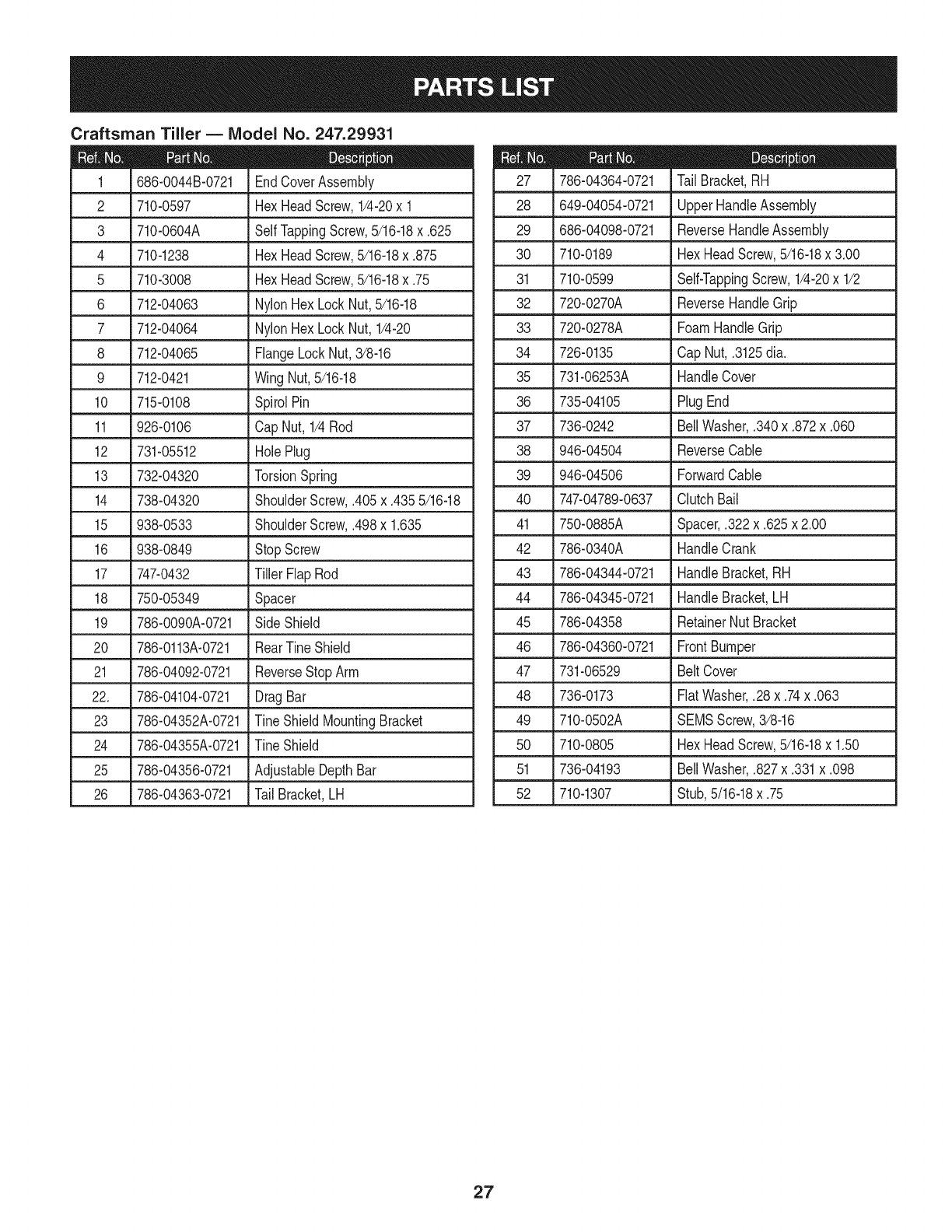
Craftsman Tiller BIViodel No. 247.29931
19
2_\15
32
12 29
18
28
Craftsman Tiller BIViodel No. 247.29931
634-04652 CompleteWhl.Ass., 13x 5 x 6 (B, C)
2 714-0143A Click Pin
3 684-04168 Idler PulleyAssembly
4 710-0331 HexHeadScrew,3/8-24x 2.25 25
5 710-0170 HexHeadScrew,5/16-24x .625 26
6 710-0599 SelfTappingScrew,1/4-20x .500 27
7 710-0606 HexHeadScrew,1/4-20x 1.50 28
8 710-0672 HexHeadScrew,5/16-18x 1.25 29
9 710-1880 HexHeadScrew,5/16-18x .75,Patch 30
10 710-3008 HexHeadScrew,5/16-18x .75,STD 31
11 712-04064 NylonHexLockNut, 1/4-20 32
12 712-0700 Nut,9/16-18,FlangeLock 33
13 718-04407 Hub, 5/8 Spline 34
14 732-04085 ExtensionSpring,.480ODX 5.00 LG 35
15 732-04276A ExtensionSpring,LT5PTO 36
16 936-0119 LockWasher,5/16 37
17 736-0173 Washer,.28x.74x.063 38
18 714-04043 InternalCotterPin 39
19 736-0343 FlatWasher,.330X 1.25X .120 40
20 936-0452 BellWasher,.396x 1.140x .095
21 736-3092 FlatWasher,.265x 1.0x .030
738-04425 ShoulderScrew,.342x.335 1/4-28
23 748-04087A PivotIdlerSpacer
24 750-04571 ShoulderSpacer,.260x.785x.538
750-04907 PivotIdlerSpacer
1916657 V-Belt,4L x 25.375Long
1916658 V-Belt,3L x 29.125Long
756-04198A EnginePulley
756-04355 TransmissionPulley
756-0625 CableRoller
786-04312 IdlerBracket,Forward
786-04343-0721 CoverPlate
786-04346
786-04416-0721
786-04415A-0721
786-04357-0721
786-04371-0721
642-04071-0721
642-04072-0721
911-0415
IdlerBracket,Reverse
MountingFrame,RH
MountingFrame,LH
PulleyBracket
PulleyShield
Tine Assembly,LH
Tine Assembly,RH
ClevisPin, .375x 1.75
41 918-04815A TransmissionAssembly
29

Craftsman Tiller B Model No. 247.29931
2
iiT
18
13
\
6
\4
19
2o \
17 18
14
21
7
13
11
1o
6
14
7
21
\
\
3O
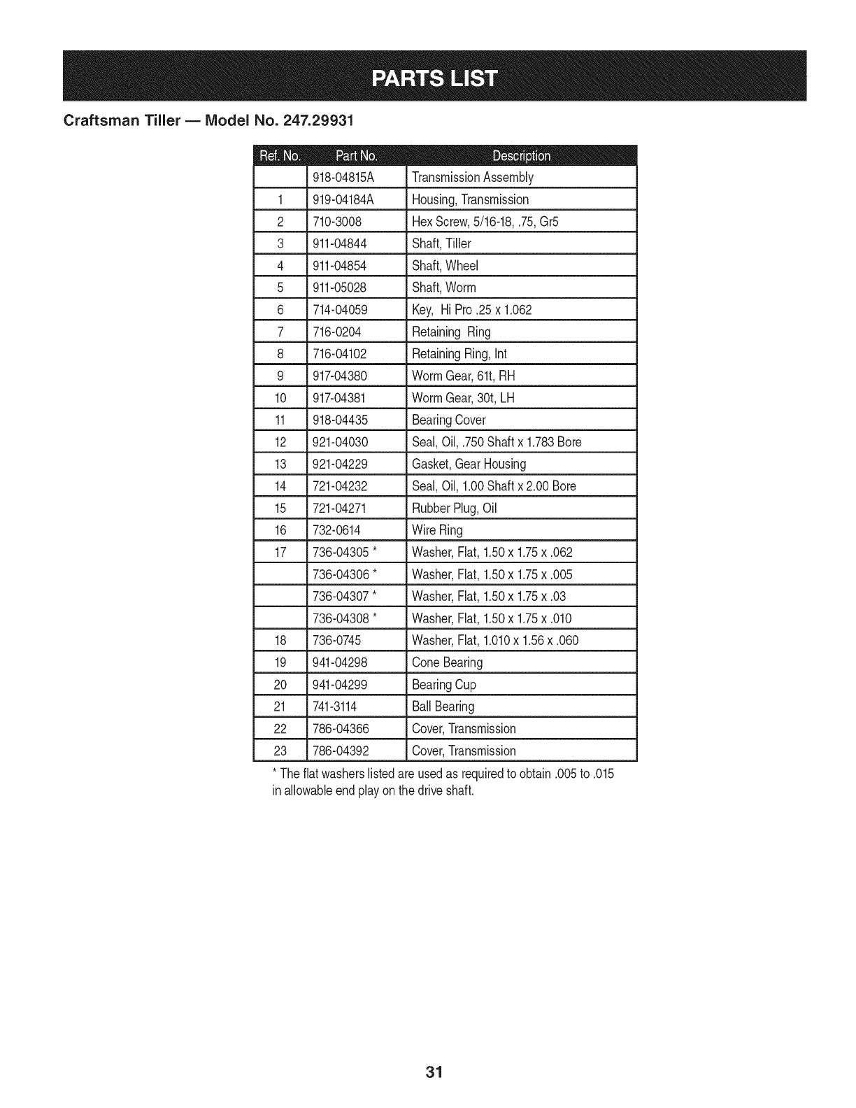
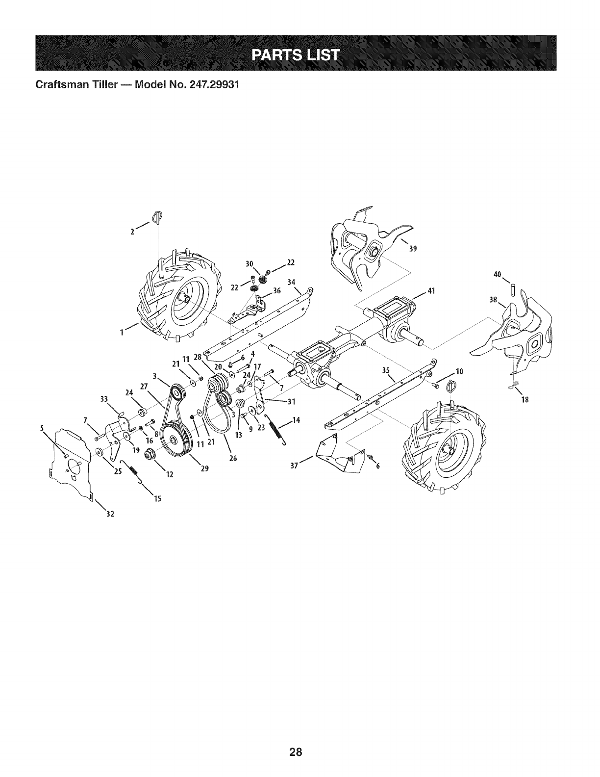
Craftsman Tiller BIViodel No. 247.29931
D = t 0
918-04815A TransmissionAssembly
1 919-04184A Housing,Transmission
2 710-3008 HexScrew,5/16-18,.75,Gr5
3 911-04844 Shaft,Tiller
4 911-04854 Shaft,Wheel
5 911-05028 Shaft,Worm
6 714-04059 Key, Hi Pro.25x 1.062
7 716-0204 Retaining Ring
8 716-04102 RetainingRing,Int
9 917-04380 WormGear,61t,RH
10 917-04381 WormGear,30t,LH
11 918-04435 BearingCover
12 921-04030 Seal,Oil, .750Shaftx 1.783Bore
13 921-04229 Gasket,GearHousing
14 721-04232 Seal,Oil, 1.00Shaftx 2.00 Bore
15 721-04271 RubberPlug,Oil
16 732-0614 Wire Ring
17 736-04305*
736-04306*
736-04307*
736-04308*
18 736-0745
19 941-04298
20 941-04299
21 741-3114
Washer,Flat,1.50x 1.75x .062
Washer,Flat,1.50x 1.75x .005
Washer,Flat,1.50x 1.75x .03
Washer,Flat,1.50x 1.75x .010
Washer,Flat,1.010x 1.56x .060
Cone Bearing
BearingCup
Ball Bearing
22 786-04366 Cover,Transmission
23 786-04392 Cover,Transmission
* Theflatwasherslistedareusedas requiredto obtain.005to .015
inallowableendplayonthe driveshaft.
31
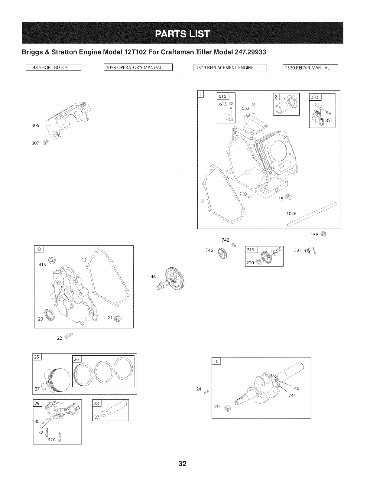
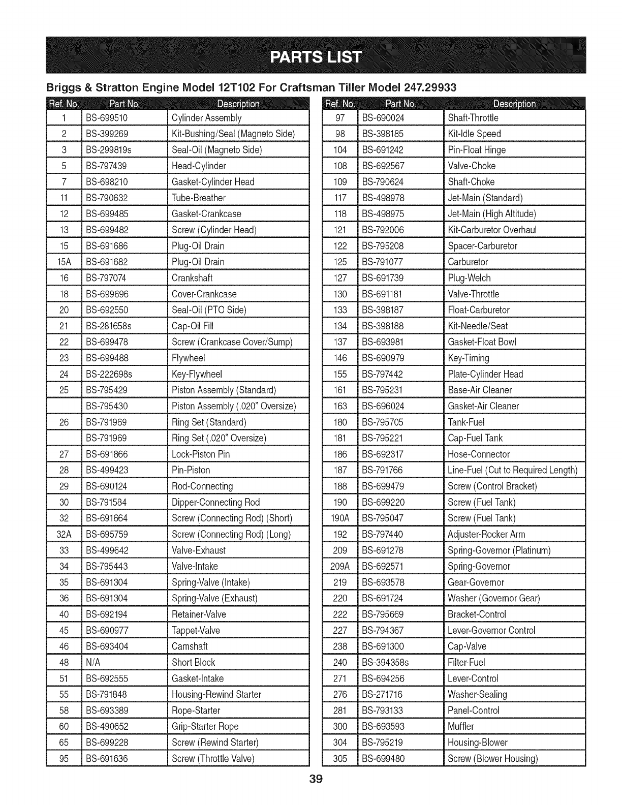
Briggs & Stratton Engine Model 12T102 For Craftsman Tiller Model 247.29933
306
307 _
1026
Y
415
12
46
742
746 _ [2191 ,_
1220_T_
22
24 0
332 _
146
741
32
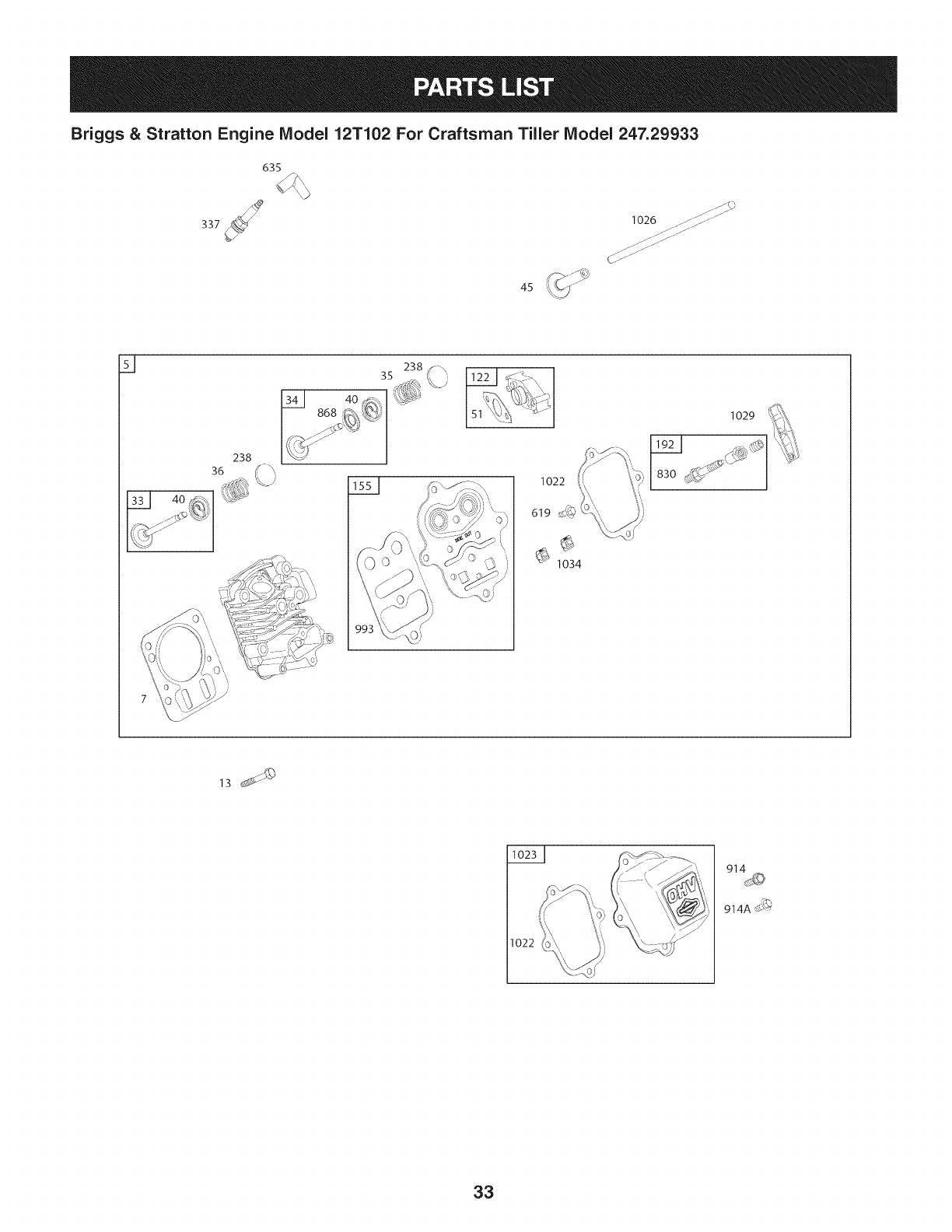
Briggs & Stratton Engine Model 12T102 For Craftsman Tiller Model 247.29933
535
45
1026 ........f;;;" .......
...... 7;;;;;;7;7;77;......
CL;7.......
Y
238
4o_
..._ t% ,i
1022
619
1034
1029
1022
914A_
33
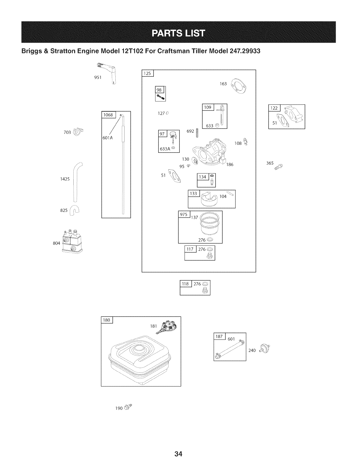
Briggs & Stratton Engine Model 12T102 For Craftsman Tiller Model 247.29933
,_)/_,,_
703 _(_
1425 [
L#
825 _
804
951
601A
127(_
51
163
692 I
lO8_
276 _?)
240
190 _
34
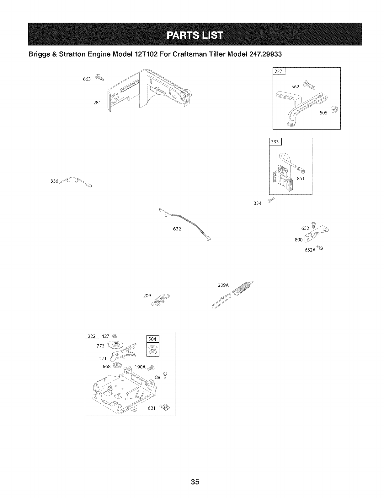
Briggs & Stratton Engine Model 12T102 For Craftsman Tiller Model 247.29933
663
281
562 'i_
356 _:: _ _ _'_
334
652A %
209
621
35
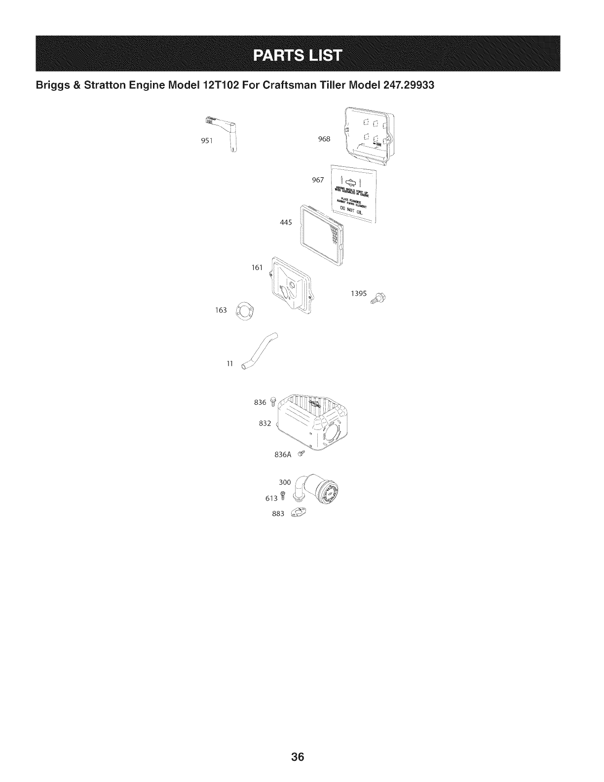
Briggs & Stratton Engine Model 12T102 For Craftsman Tiller Model 247.29933
951 i i 968
161
163
11
836A
36

Briggs & Stratton Engine Model 12T102 For Craftsman Tiller Model 247.29933
23
lOOS,),_,_,_,_!
1070 _ _
/
332
1211
1210
I
456
689 17_
304
\\
305 _
I 1036 EMISSIONS LABEL I
37
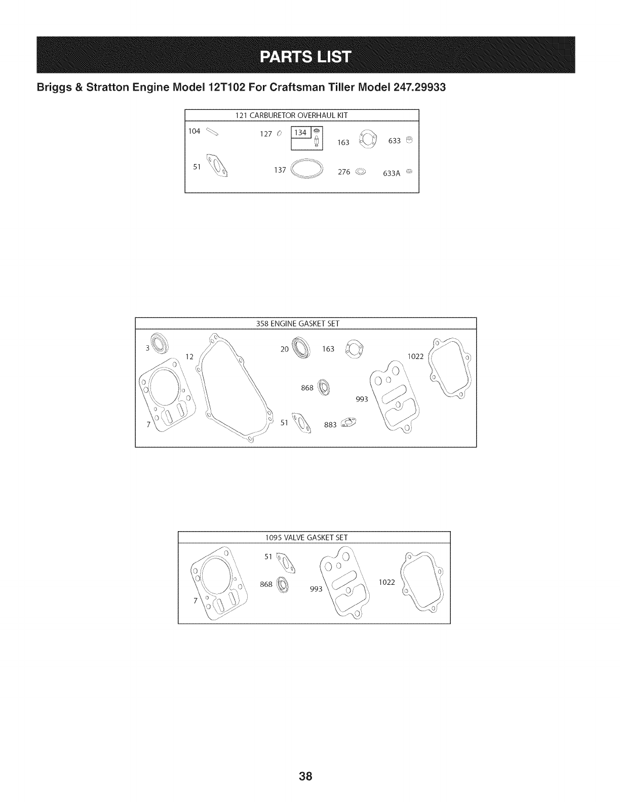
Briggs & Stratton Engine Model 12T102 For Craftsman Tiller Model 247.29933
104 %_,
51
121 CARBURETOR OVERHAUL KIT
127 0
163 633 _
633A _
358 ENGINE GASKET SET
20 163
868
51
993
883_?S
1095 VALVE GASKET SET
S1 _)\
868
0
99; 1022
38
Briggs & Stratton Engine IViodel 12T102 For Craftsman Tiller IViodel 247.29933
|= 0* |= l=
BS-699510 CylinderAssembly BS-690024 Shaft-Throttle
BS-399269 Kit-Bushing/Seal(MagnetoSide) 98 BS-398185 Kit-IdleSpeed
2
3 BS-299819s Seal-Oil(MagnetoSide)
5 BS-797439 Head-Cylinder
7 BS-698210 Gasket-CylinderHead
11 BS-790632 Tube-Breather
12 BS-699485 Gasket-Crankcase
L
13 BS-699482 Screw(CylinderHead)
15 BS-691686 Plug-OilDrain
15A BS-691682 LPlug-OilDrain
16 BS-797074 Crankshaft
18 BS-699696 Cover-Crankcase
20 BS-692550 Seal-Oil(PTOSide)
21 BS-281658s Cap-OilFill
22 BS-699478 Screw(CrankcaseCover/Sump)
23 BS-699488 Flywheel
24 BS-222698s Key-Flywheel
104 BS-691242 Pin-FloatHinge
108 BS-692567 Valve-Choke
109 BS-790624 Shaft-Choke
117 BS-498978 Jet-Main(Standard)
118 BS-498975 Jet-Main(HighAltitude)
121 BS-792006 Kit-CarburetorOverhaul
122 BS-795208 Spacer-Carburetor
125 BS-791077 Carburetor
25 . BS-795429 LPistonAssembly(Standard)
127 BS-691739 Plug-Welch
130 BS-691181 Valve-Throttle
133 BS-398187 Float-Carburetor
134 BS-398188 Kit-Needle/Seat
137 BS-693981 Gasket-FloatBowl
146 BS-690979 Key-Timing
155 BS-797442 Plate-CylinderHead
161 BS-795231 Base-AirCleaner
BS-795430 PistonAssembly(.020"Oversize)
26 BS-791969 RingSet (Standard)
BS-791969 RingSet (.020"Oversize)
27 BS-691866 Lock-PistonPin
28 BS-499423 Pin-Piston
29 BS-690124 Rod-Connecting
30 BS-791584 Dipper-ConnectingRod
32 _BS691664 Screw(ConnectingRod) (Short)
32A BS-695759 Screw(ConnectingRod) (Long)
33 BS-499642 Valve-Exhaust
34 BS-795443 Valve-Intake
35 BS-691304 Spring-Valve(Intake)
36 BS-691304 Spring-Valve(Exhaust)
40 BS-692194 Retainer-Valve
45 BS-690977 Tappet-Valve
46 BS-693404 Camshaft
163 BS-696024 Gasket-AirCleaner
180 BS-795705 Tank-Fuel
181 BS-795221 Cap-FuelTank
186 BS-692317 Hose-Connector
187 BS-791766 Line-Fuel(Cutto RequiredLength)
188 BS-699479 Screw(ControlBracket)
190 BS-699220 Screw(FuelTank)
190A BS-795047 Screw(FuelTank)
192 BS-797440 Adjuster-RockerArm
209 BS-691278 Spring-Governor(Platinum)
209A BS-692571 Spring-Governor
219 BS-693578 Gear-Governor
220 BS-691724 Washer(GovernorGear)
222 BS-795669 Bracket-Control
227 BS-794367 Lever-GovernorControl
238 BS-691300 Cap-Valve
48 N/A ShortBlock
51 BS-692555 Gasket-Intake
55 BS-791848 Housing-RewindStarter
58 BS-693389 Rope-Starter
60 BS-490652 Grip-StarterRope
65 BS-699228 Screw(RewindStarter)
95 BS-691636 Screw(ThrottleValve)
39
240 BS-394358s Filter-Fuel
271 BS-694256 Lever-Control
276 BS-271716 Washer-Sealing
281 BS-793133 Panel-Control
300 BS-693593 Muffler
304 BS-795219 Housing-Blower
305 BS-699480 Screw(BlowerHousing)
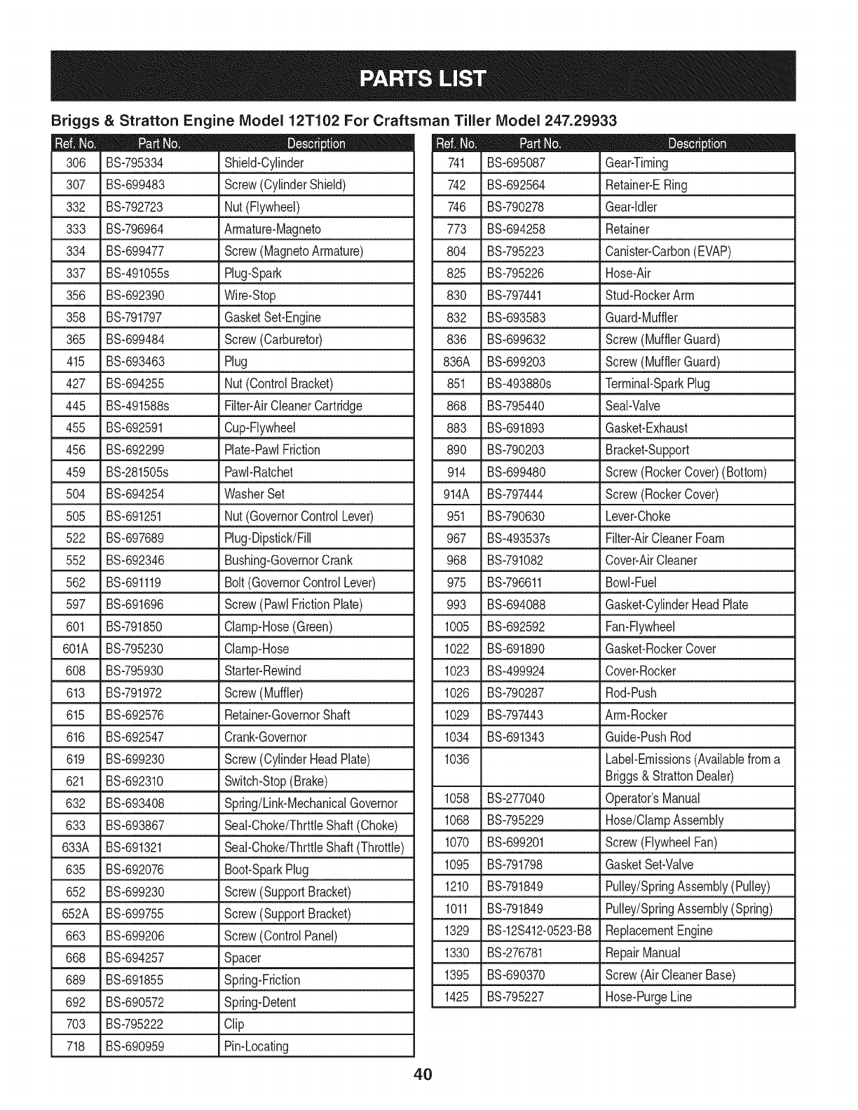
Briggs & Stratton Engine IViodel 12T102 For Craftsman Tiller IViodel 247.29933
D = 0
BS-795334 Shield-Cylinder
307 BS-699483 Screw(CylinderShield)
332 BS-792723 Nut(Flywheel)
333 BS-796964 Armature-Magneto
334 BS-699477 Screw(MagnetoArmature)
337 BS-491055s Plug-Spark
356 BS-692390 Wire-Stop
358 BS-791797 GasketSet-Engine
365 BS-699484 Screw(Carburetor)
415 BS-693463 Plug
427 BS-694255 Nut(ControlBracket)
445 BS-491588s Filter-AirCleanerCartridge
455 BS-692591 Cup-Flywheel
456 BS-692299 Plate-PawlFriction
459 BS-281505s PawI-Ratchet
504 BS-694254 WasherSet
505 BS-691251 Nut(GovernorControlLever)
522 BS-697689 Plug-Dipstick/Fill
552 BS-692346 Bushing-GovernorCrank
562 BS-691119 Bolt(GovernorControlLever)
597 BS-691696 Screw(PawlFrictionPlate)
601 BS-791850 Clamp-Hose(Green)
601A BS-795230 Clamp-Hose
608 BS-795930 Starter-Rewind
613 BS-791972 Screw(Muffler)
615 BS-692576 Retainer-GovernorShaft
616 BS-692547 Crank-Governor
619 BS-699230 Screw(CylinderHeadPlate)
621 BS-692310 Switch-Stop(Brake)
632 BS-693408 Spring/Link-MechanicalGovernor
633 BS-693867 SeaI-Choke/ThrttleShaft(Choke)
633A BS-691321 SeaI-Choke/ThrttleShaft(Throttle)
635 BS-692076 Boot-SparkPlug
652 BS-699230 Screw(SupportBracket)
652A BS-699755 Screw(SupportBracket)
663 BS-699206 Screw(ControlPanel)
668 BS-694257 Spacer
689 BS-691855 Spring-Friction
692 BS-690572 Spring-Detent
703 BS-795222 Clip
718 BS-690959 Pin-Locating
D = O O
BS-695087 Gear-Timing
742 BS-692564 Retainer-ERing
746 BS-790278 Gear-Idler
773 BS-694258 Retainer
804 BS-795223 Canister-Carbon(EVAP)
825 BS-795226 Hose-Air
830 BS-797441 Stud-RockerArm
832 BS-693583 Guard-Muffler
836 BS-699632 Screw(MufflerGuard)
836A BS-699203 Screw(MufflerGuard)
851 BS-493880s Terminal-SparkPlug
868 BS-795440 Seal-Valve
883 BS-691893 Gasket-Exhaust
890 BS-790203 Bracket-Support
914 BS-699480 Screw(RockerCover)(Bottom)
914A BS-797444 Screw(RockerCover)
951 BS-790630 Lever-Choke
967 BS-493537s Filter-AirCleanerFoam
968 BS-791082 Cover-AirCleaner
975 BS-796611 Bowl-Fuel
993 BS-694088 Gasket-CylinderHeadPlate
1005 BS-692592 Fan-Flywheel
1022 BS-691890 Gasket-RockerCover
1023 BS-499924 Cover-Rocker
1026 BS-790287 Rod-Push
1029 BS-797443 Arm-Rocker
1034 BS-691343 Guide-PushRod
1036 Label-Emissions(Availablefroma
Briggs& StrattonDealer)
1058 BS-277040 Operator'sManual
1068 BS-795229 Hose/ClampAssembly
1070 BS-699201 Screw(FlywheelFan)
1095 BS-791798 GasketSet-Valve
1210 BS-791849 Pulley/SpringAssembly(Pulley)
1011 BS-791849 Pulley/SpringAssembly(Spring)
1329 BS-12S412-0523-B8 ReplacementEngine
1330 BS-276781 RepairManual
1395 BS-690370 Screw(AirCleanerBase)
1425 BS-795227 Hose-PurgeLine
4O

Craftsman Tiler IViodel No. 247.29931
777S33496 777X43688
USEE850R
THANIO%ETHANOL
777120358
777D14197 777i22969 777122968
WHEELS
REVERSE
TINES
FORWARD
I]OINYEI
RQTATINI
Ii
WHEELS
FIIWAII
41

(Thispageapplicableinthe U.S.A.and Canadaonly.)
Sears Brands Management Corporation (Sears), the California Air Resources Board (CARD)
and the United States Environmental Protection Agency (U.S. EPA)
Emission Control System Warranty Statement (Owner's Defect Warranty Rights and Obligations)
EMISSIONCONTROLWARRANTYCOVERAGEISAPPLICABLETOCERTI-
FIEDENGINESPURCHASEDINCALIFORNIAIN1995ANDTHEREAF-
TER,WHICHARE USEDINCALIFORNIA,ANDTOCERTIFIEDMODEL
California and United States Emission
The CaliforniaAir ResourcesBoard(CARD),U.S.EPAand Searsare pleased
to explainthe EmissionControlSystemWarrantyonyour modelyear2000and
latersmalloff-roadengine(SORE).InCalifornia,newsmall off-roadengines
mustbedesigned,builtand equippedto meettheState'sstringentanti-smog
standards.Elsewherein theUnitedStates,newnon-road,spark-ignition
enginescertifiedfor modelyear 1997and latermustmeetsimilarstandardsset
forthbythe U.S.EPA.Searsmustwarranttheemissioncontrolsystemon your
YEAR1997ANDLATERENGINESWHICHARE PURCHASEDANDUSED
ELSEWHEREINTHEUNITEDSTATES(ANDAFTERJANUARY1,2001 IN
CANADA).
Control Defects Warranty Statement
enginefor theperiodsoftime listedbelow,providedtherehasbeen noabuse,
neglector impropermaintenanceof your smalloff-roadengine.Youremis-
sion controlsystemincludespartssuch as thecarburetor,air cleaner,ignition
system,mufflerand catalyticconverter.Also includedmaybe connectorsand
otheremissionrelatedassemblies.Wherea warrantableconditionexists,Sears
will repairyour smalloff-roadengineat no costto you includingdiagnosis,parts
and labor.
Sears Emission Control Defects Warranty Coverage
Smalloff-roadenginesarewarrantedrelativeto emissioncontrolpartsdefects
fora periodof one year,subjectto provisionsset forth below.Ifanycovered
Owner's Warranty
Asthe smalloff-roadengineowner,you are responsiblefor theperformanceof
therequiredmaintenancelistedin yourOperatingand MaintenanceInstruc-
tions.Searsrecommendsthatyouretainall yourreceiptscoveringmaintenance
onyoursmalloff-roadengine,butSearscannotdenywarrantysolelyfor the
lackof receiptsorfor yourfailureto ensurethe performanceof allscheduled
maintenance.As the smalloff-roadengineowner,youshouldhoweverbe
awarethat Searsmaydenyyou warrantycoverageif your smalloff-roadengine
ora part hasfaileddueto abuse,neglect,impropermaintenanceor unap-
parton yourengineis defective,the partwillbe repairedorreplacedbySears.
Responsibilities
provedmodifications.Youare responsiblefor presentingyour smalloff-road
engineto anAuthorizedSearsServiceDealeras soonas a problemexists.The
undisputedwarrantyrepairsshouldbe completedina reasonableamountof
time,notto exceed30 days.Ifyouhaveanyquestionsregardingyourwarranty
rightsand responsibilities,youshouldcontacta SearsService Representative
at 1-800-469-4663.The emissionwarrantyis a defectswarranty.Defectsare
judgedon normalengineperformance.Thewarrantyis notrelatedto an in-use
emissiontest.
Sears Emission Control Defects Warranty Provisions
ThefollowingarespecificprovisionsrelativetoyourEmissionControlDefectsWarrantyCoverage.ItisinadditiontotheSearsenginewarrantyfornon-regulated
enginesfoundin theOperatingand MaintenanceInstructions.
1. WarrantedParts
Coverageunderthis warrantyextendsonly to the parts listedbelow (the
emissioncontrolsystemsparts)to the extentthese partswere presenton
the enginepurchased.
a. FuelMeteringSystem
•Cold start enrichmentsystem
•Carburetorand internalparts
•FuelPump
b. AirlnductionSystem
•Aircleaner
•Intakemanifold
c. IgnitionSystem
•Sparkplug(s)
•Magnetoignitionsystem
d. CatalystSystem
•Catalyticconverter
•Exhaustmanifold
•Air injectionsystemor pulsevalve
e. MiscellaneousItemsUsedin AboveSystems
•Vacuum,temperature,position,timesensitivevalves
andswitches
•Connectorsandassemblies
2. Lengthof Coverage
Searswarrantsto the initialownerand eachsubsequentpurchaserthat
the WarrantedParts shallbe free fromdefects in materialsandworkman-
shipwhich causedthefailure of the WarrantedPartsfor a periodof one
yearfromthe datethe engineis deliveredto a retailpurchaser.
3. NoCharge
Repairor replacementof anyWarrantedPartwill beperformedat no
chargeto the owner,includingdiagnosticlabor whichleadsto the
determinationthata WarrantedPartisdefective,ifthe diagnosticworkis
performedat an AuthorizedSears ServiceDealer.Foremissionswarranty
servicecontact yournearestAuthorizedSears ServiceDealeras listed in
the "YellowPages"under"Engines,Gasoline,""GasolineEngines,""Lawn
Mowers,"orsimilarcategory.
4. Claimsand CoverageExclusions
Warrantyclaimsshall be filed in accordancewiththe provisionsof the
SearsEngineWarrantyPolicy.Warrantycoverageshall be excludedfor
failuresof WarrantedPartswhichare notoriginal Searspartsor because
of abuse,neglector impropermaintenanceas setforth inthe Sears
EngineWarrantyPolicy.Sears isnotliableto coverfailuresof Warranted
Partscausedby theuseof add-on,non-original,or modifiedparts.
5. Maintenance
Any WarrantedPart whichis not scheduledfor replacementas required
maintenanceor whichis scheduledonly for regularinspectionto the effect
of "repairor replaceas necessary"shallbe warrantedasto defectsfor the
warrantyperiod.Any WarrantedPartwhich isscheduledfor replacement
as requiredmaintenanceshallbe warrantedasto defectsonly forthe
periodof time up to the first scheduledreplacementfor that part.Any
replacementpart that isequivalentin performanceand durabilitymay
be usedin the performanceof any maintenanceor repairs.The owneris
responsibleforthe performanceof allrequiredmaintenance,as definedin
the SearsOperatingand MaintenanceInstructions.
6. ConsequentialCoverage
Coveragehereundershallextend to thefailure of any enginecomponents
caused bythe failureof any WarrantedPartstill underwarranty.
Inthe USAandCanada,a 24 hourhotline, 1-800-469-4663,hasa menuof pre-recordedmessagesofferingyou enginemaintenanceinformation.
GD0C-100188Rev.B
42
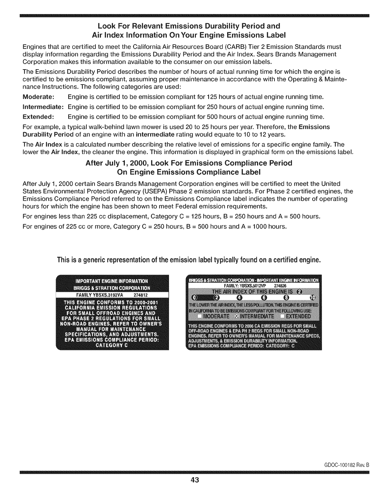
Look For Relevant Emissions Durability Period and
Air index information On Your Engine Emissions Label
Engines that are certified to meet the California Air Resources Board (CARB) Tier 2 Emission Standards must
display information regarding the Emissions Durability Period and the Air Index. Sears Brands Management
Corporation makes this information available to the consumer on our emission labels.
The Emissions Durability Period describes the number of hours of actual running time for which the engine is
certified to be emissions compliant, assuming proper maintenance in accordance with the Operating & Mainte-
nance Instructions. The following categories are used:
Moderate: Engine is certified to be emission compliant for 125 hours of actual engine running time.
Intermediate: Engine is certified to be emission compliant for 250 hours of actual engine running time.
Extended: Engine is certified to be emission compliant for 500 hours of actual engine running time.
For example, a typical walk-behind lawn mower is used 20 to 25 hours per year. Therefore, the Emissions
Durability Period of an engine with an intermediate rating would equate to 10 to 12 years.
The Air index is a calculated number describing the relative level of emissions for a specific engine family. The
lower the Air Index, the cleaner the engine. This information is displayed in graphical form on the emissions label.
After July 1,2000, Look For Emissions Compliance Period
On Engine Emissions Compliance Label
After July 1, 2000 certain Sears Brands Management Corporation engines will be certified to meet the United
States Environmental Protection Agency (USEPA) Phase 2 emission standards. For Phase 2 certified engines, the
Emissions Compliance Period referred to on the Emissions Compliance label indicates the number of operating
hours for which the engine has been shown to meet Federal emission requirements.
For engines less than 225 cc displacement, Category C = 125 hours, B = 250 hours and A = 500 hours.
For engines of 225 cc or more, Category C = 250 hours, B = 500 hours and A = 1000 hours.
This is ageneric representation of the emission label typically found on a certified engine.
FAMILYYBSXS.3192VA 274812
GDOC-100182Rev.B
43
Congratulationson makinga smartpurchase.YournewCraftsman@
productis designedandmanufacturedfor yearsof dependableopera-
tion.But likeall products,it may requirerepairfromtimeto time.That's
whenhavinga RepairProtectionAgreementcansaveyoumoneyand
aggravation.
Here'swhatthe RepairProtectionAgreement*includes:
* Expert service byour 10,000professionalrepairspecialists
oUnlimitedserviceand no chargefor partsand laboron all
coveredrepairs
o Product replacementupto $1500if yourcoveredproductcan't be
fixed
•Discountof 10%from regularprice of serviceand relatedinstalled
partsnotcoveredby theagreement;also,10%off regularpriceof
preventivemaintenancecheck
• Fast help by phone- we call it RapidResolution- phonesupport
froma Searsrepresentative.Thinkof usas a "talkingowner's
manual."
Onceyou purchasethe Agreement,a simplephonecall is all thatit
takesfor youto scheduleservice.Youcan call anytimedayor night,or
schedulea serviceappointmentonline.
The RepairProtectionAgreementis a risk-freepurchase.If youcancel
for any reasonduringthe productwarrantyperiod,wewill provideafull
refund.Or,a proratedrefundanytimeafterthe productwarrantyperiod
expires.Purchaseyour RepairProtectionAgreementtoday!
Somelimitationsand exclusionsapply. For pricesand additional
informationin the U.S.A.call 1-800-827-6655.
*Coverage inCanadavaries on some items.Forfull details call
Sears Canadaat 1-800-361-6665.
Sears Installation Service
ForSearsprofessionalinstallationof homeappliances,garagedoor
openers,waterheaters,andothermajorhomeitems,in the U.S.A.or
Canadacall 1-800-4-MY-HOME®.
44
Declaraci6n de garantia ........................ Pb,gina 45
Medidas importantes de seguridad ..... Pb,ginas 46-49
Armado ................................................. Pb,ginas 50-51
Funcionamiento .................................... Pb,ginas 52-59
Servicio y Mantenimiento ..................... P_.ginas 60-65
Almacenamiento fuera de temporada.. Pb,gina 66
Soluci6n de problemas ......................... P_,gina 67
Acuerdo de protecci6n para reparaciones Pb,g ina 71
NQmero de servicio ............................... Cubierta posterior
GARANTIA COMPLETACRAFTSMAN
Encondicionesnormalesdefuncionamientoy mantenimientoconformealas instruccionessuministradas,si esteproductoCraftsmanfalla
debidoa defectosen los materialeso enla manodeobradentrode losdos a_osde iafechadecompra,comuniquesecon 1-800-4-MY-HOME®
paraorganizarsu reparaci6nsincargo (o reemplazosi resultaraimposiblerepararla).
Lagaranfias61oserAv_lidadurante90 dias a partirde lafechadecomprasi esteproductose usaen cualquiermomentoparafinescomerciales
ode alquiler.
EstagaranfiacubreONICAMENTElosdefectosenlos materialesy la manode obra.SearsNO pagar_por:
• Componentesdesechablesque sedesgastancon el usonormal,incluyendosin limitaci6nlas cuchillas,losdientesy las correas.
• Reemplazoo reparaci6nde neum_ticoso ruedascomoresultadodel desgastenormal,unaccidente,o funcionamientoo mantenimiento
incorrectos.
• Reparacionesnecesariascomo resultadodel abusodel operador,incluyendosin limitaci6nelda_oocasionadoporimpactarobjetosque
tuercenlaestructurao el cig(Je_al.
• Reparacionesnecesariascomo resultadode la negligenciadeloperador,incluyendosin limitaci6nda_oel@tricoy mecanicodebidoal
almacenamientoinadecuado,o porno habermantenidoelequipoconformealas instruccionescontenidasenel manualdel operador.
• Reparacionesnecesariasdebidoal usode unamezcladecombustibleincorrecta,combustiblecontaminadoo viejo.
• Eldeterioroy desgastenormaldelos acabadosexteriores,o reemplazode laetiquetadelproducto.
Estagaranfiaaplicasolamentemientrasel productoest_dentrode los EstadosUnidos.
Estagaranfialeotorgaderechoslegalesespecificos,peroustedpodriagozarde otrosderechosen raz6nde su lugarde residencia.
Sears, Roebuck and Co., Hoffman Estates, IL 60179
Seriedel motor:
Tipodeaceitedelmotor:
Capacidadde aceitedel motor:
Combustible:
Bujia:
Separaci6ndelas bujias:
205cc
SAE3O
20onzas
Gasolinasin plomo
Champion@RC-12YC
.030"
N_rnerode modelo ..........................................................
N_rnerode serie..............................................................
Fechade eornpra.............................................................
Registreel nQmerodemodelo,nQmerode serie
y fechade compram_sarriba
@Sears Brands,LLC 45
Lapresenciadeestesimboloindicaquesetratadeinstruccionesde
seguridadimportantesquesedebenrespetarparaevitarponerenpeligro
suseguridadpersonaly/omaterialyladeotraspersonas.Leaycumpla
todaslasinstruccionesdeestemanualantesdeintentaroperaresta
m&quina.Sinorespetaestasinstruccionespuedeprovocarlesiones
personales.Cuandoveaestesimbolo,ipresteatenci6nalaadvertencia!
Estam&quinaest&diseSadaparaserutilizadarespetandolasnormas
deseguridadcontenidasenestemanual.AIigualqueconcualquiertipo
deequipomotorizado,undescuidooerrorporpartedeloperadorpuede
producirlesionesgraves.Estam_quinaescapazdeamputardedos,
manosypiesydearrojarresiduos.Denorespetarlasinstruccionesde
seguridadsiguientessepuedenproducirlesionesgravesolamuerte.
PROPOSICION 65 DE CALiFORNiA
Elescapedel motorde esteproducto,algunosdesus componentesy
algunoscomponentesdel vehiculocontieneno liberansustanciasquimicas
que el estadode Californiaconsideraque puedenproducirc&ncer,
defectosdenacimientou otrosproblemasreproductivos.Loshomesdela
bateriaylos accesoriosalinescontienenplomoy compuestosde plomo,
sustanciasquimicasque segQnIo establecidopor el Estadode California
causanc&ncery daSosen el sistemareproductivo.L&veselas manos
despuesdeestar encontactoconestoscomponentes.
Su responsabilidad--Lirnite eluso deesta rn_.quinarnotorizada
alas personasque lean,cornprendany curnplanlas advertenciase
instruccionesqueaparecenenestemanualy en larn_.quina.
i6UARDEESTASINSTRUCCIONES!
CAPACITACION
• Lea,cornprenday respetetodaslas instruccionesquefiguranen
la rn_.quinayen el o los rnanualesantesde procederaarrnarlay
hacerlafuncionar.Guardeestemanualen un lugarseguropara
consultasfuturasy peri6dicas,asi cornoparasolicitarrepuestos.
• Leael manualdeloperadory sigatodaslas advertenciase
instruccionesdeseguridad.De nohacerlo,puedeocasionar
heridasde gravedadal operadory/oa losobservadores.Ante
cualquierduda,Ilarneal 1-800-4MY-HOME.
•Farniliaricesecontodoslos controlesy su correcto
funcionarniento.Sepac6rnodetenerla rn_.quinay c6rno
desconectarloscontrolesr_.pidarnente.
• No perrnitanuncaque losni_os rnenoresde 14a_osutilicen
estarn_.quina.Los ni_osde 14a_osenadelantedebenleery
entenderlas instruccionesde operaci6ny norrnasdeseguridad
contenidasen estemanualyen larn_.quinay debenser
entrenadosy supervisadosporun adulto.
•Nuncaperrnitaquelos adultosoperenestarn_quinasin recibir
antesla instrucci6napropiada.
• Mantengaa los observadores,rnascotasy ni_osal rnenosa 25
metrosde la rn_.quinarnientrasest,.en funcionarniento.Detenga
la rn_.quinasi alguienseacerca.
• Nuncaenciendael motorenespacioscerradoso enunazona
con pocaventilaci6n.Elescapedel motorcontienernon6xidode
carbono,un gasinodoroy letal.
PREPARATIVOS
•Reviserninuciosarnenteel &readondese va a usarel equipo.
Retiretodaslas piedras,botellas,latasy otrosobjetosextra_os
que puedanserlevantadoso arrojadoscausandolesiones
personaleso da_osa larn_.quina.
•Paraprotegerselosojos,utilicesiernpregalas o anteojosde
seguridadrnientrasoperala rn_.quinao rnientraslaajustao
repara.Losobjetosarrojadosquerebotanpuedenproducir
lesionesocularesgraves.
•Utilicezapatosde trabajoresistentes,desuelafuerte,y
pantalonesy carnisasajustados.Lasprendassueltasy las
alhajasse puedenengancharen las piezasrn6viles.Nuncaopere
estarn_.quinaestandodescalzoocon sandalias.
•Antesde encenderla rn_quinacontrolequetodoslos pernosy
tornillosest_nbienajustadosparagarantizarquela rn_.quinase
encuentraen condicionessegurasdeoperaci6n.Adern_.s,realice
una inspecci6nvisualde la rn_.quinaa intervalosfrecuentespara
controlarsi la rnisrnaest,.da_ada.
•Antesde arrancarel motor,desenganchelas palancasdel
ernbraguey despl_.celas(en casode haber)a la posici6nneutral
("N").
•Nuncadejelarn_.quinaen funcionarnientosin vigilancia.
•Nuncaintenterealizarajustesrnientrasel motorest,.enrnarcha,
exceptoen los casosespedficarnenterecornendadosenel
manualdel operador.
•Mantengao reernplacelas etiquetasdeseguridade instrucciones
segQnsea necesario.
46
Manejo seguro de la gasoJina:
Paraevitar lesionespersonalesy da_os materialestengamuchocuidadoal
manipularla gasolina.Lagasolinaes sumamenteinflamableysus vapores
puedencausarexplosiones.Si se derramagasolinaencimao sobrela ropa
se puedelesionargravementeya que se puedeincendiar. Lavesela piely
c_mbiesede ropade inmediato.
• Utilices61olosrecipientesparagasolinaautorizados.
• NuncaIlenelosrecipientesenel interiordeun veh[culoo cami6no
cajade remolquecon unrecubrimientopl_stico.Coloquesiemprelos
recipientesen el pisoy lejosdel veh[culoantes de Ilenarlos.
• Cuandoseafactible,retireel equipo a gasolinadel cami6no remolquey
Ileneloenel suelo.Siesto no es posible,Ileneel equipoen unremolque
concontenedorport_til,en vezde desdeuna boquilladispensadorade
gasolina.
• Mantengala boquillaencontactocon el hordedel tanquede
combustibleo de laabertura del recipienteen todo momento,hasta
terminarde cargar.Noutilice un dispositivoparaabrir/cerrarla boquilla.
• Apaguetodos los cigarrillos,cigarros,pipasy otrasfuentesde
combusti6n.
• Nuncacarguecombustibleen la m_quinaen unespacio cerrado.
• Nuncasaquela tapade la gasolinani agreguecombustiblemientrasel
motorest_calienteo en marcha.Permitaque el motorse enfr[epot Io
menosdos minutosantesde volvera cargar combustible.
• Nuncalleneen excesoel tanquede combustible.Lleneel tanque no
m_sde Y2pulgadapor debajo dela basedel cuello del tap6ndecarga,
paradejarespacio para laexpansi6ndel combustible.
• Vuelvaa colocarla tapadel combustibley ajOstelabien.
• Limpiela gasolinaquese puedahaberderramadosobreel motoro el
equipo.Trasladela m_quinaa otra zona.Espere5 minutosantesde
encenderel motor.
• Parareducirel riesgode incendio,mantengala m_quinalimpiade
pasto,hojasy de acumulaci6nde otrosescombros.Limpie losderrames
deaceiteo combustibleysaque todoslos escombrosembebidosde
combustible.
• Nuncaguardela m_quinao el recipientede combustibleen unespacio
cerradodonde hayafuego,chispaso luzpiloto,como porejemplode
calentadoresdeagua,calefactoresde ambientes,hornos,secadoresde
ropau otrosaparatosa gas.
FUNCIONAMIENTO
•Nocoloquelas manosni los piescerca depiezasgiratorias.Elcontacto
conlas piezasgiratoriaspuedeocasionaren la amputaci6ndemanos
o pies.
• No utilicela m_quinabajola influenciadel alcoholo lasdrogas.
• Nuncaopereestam_quinasino hay buenavisibilidado iluminaci6n.
Siempredebe estarsegurode queest_ bienafirmadoysujetando
firmementelas manijas.
• Mantengaa los transeL]ntesalejadosde lam_quinamientrasla misma
est_en funcionamiento.Detengala m_quinasi alguiense acerca.
• Tengacuidadoal labrarunterrenoduro.Los dientespuedenclavarseen
latierra e impulsarlacultivadorahaciaadelante.Si estoocurre,suelteel
manubrioy dejela m_quinalibre.
• Seasumamenteprecavidocuandoopere la m_quinasobreuna
superficiecongrava o al cruzarla.Mantengasealerta por si se
presentanpeligrosocultoso tr_nsito.Notransportepasajeros.
• Nuncautilicela m_quinaa altasvelocidadesde desplazamientosobre
superficiesduraso resbaladizas.
• Tengacuidadoparaevitarresbalaro caerse.
• Mire haciaabajo y haciaarrasy tengacuidadocuandose desplaceen
marchaarraso cuandojale de la m_quinahaciausted.
• Arranqueel motorde acuerdocon lasinstruccionesdel manualy aleje
los piesde losdientesen todo momento.
•Si golpeaalgQnun objetoextra_oo si la m_quinacomienzaa emitir
unsonidopococomL]no a vibrar,apagueel motorde inmediato.
Desconecteel cablede labuj[a, p6ngalohaciendomasacontrael motor
y siga los pasossiguientes:
a. Inspeccionela m_quinapara vet si est_da6ada.
b. Repareo reemplacelas piezasda_adas.
c. Controlesi hay piezasflojas y ajQstelaspara asegurarque la
m_quinafuncionede maneraseguray continua.
• Desenganchetodaslas palancasdeembrague(si lashay)y detengael
motorantes de dejarla posici6nde operaci6n(detr_sde las manijas).
Esperehastaque los dientesse detengancompletamenteantes de
limpiarlos,haceralgQnajusteo inspeccionarlos.
• Nuncaenciendael motorenespacioscerradoso en unazonacon poca
ventilaci6n.Elescape del motorcontienemon6xidode carbono,un gas
inodoroy letal.
• Elsilenciadory el motorse calientany puedencausarquemaduras.No
lostoque.
• Tengaprecauci6ncuandolabreterrenocercade vallas,edificios y
serviciossubterr_neos.LosdientesrotatoriospuedencausardaSos
materialeso lesionespersonales.
• Nosobrecarguela capacidaddela m_quinaintentandolabrarel sueloa
unniveldemasiadoprofundoo a unavelocidaddemasiador@ida.
• Si la m_quinaarrancahaciendoun sonidoo unavibraci6nrata, detenga
el motor,desconecteelcablede la buj[aycon@telo a masacontrael
motor.Inspeccionela m_quinaminuciosamenteparaver si est_ da6ada.
Reparetodos los da_osantes de encendery operarla m_quina.
• Mantengatodos los escudos,protectoresy dispositivosdeseguridaden
su lugaryen correctofuncionamiento.
• Nuncalevanteo transportela m_quinacuandoel motorest_encendido.
• Utilices61odispositivosdesujeci6no accesoriosaprobadosporel
fabricanteque figuranen laspaginasde la listade piezasdeeste
manualdel operador.Si noIo hace,puedenproducirselesiones
personales.
• Si se presentansituacionesque no est_n previstasen estemanual,sea
cuidadosoy useel sentidocomL]n.P6ngaseencontactocon Asistencia
al Clienteparasolicitarayuday el hombredel distribuidordeservicio
m_scercano.
MANTENIMIENTO Y ALMACENANIIENTO
•Mantengala m_quina,losaditamentosy accesoriosen condicionesde
funcionamientoseguro.
• Dejequela m_quinase enfr[epor Io menoscincominutosantes
de guardarla.Nuncaalterelosdispositivosdeseguridad.Controle
peri6dicamentequefuncionancorrectamente.
• Verifiquefrecuentementeque lospernosytornillosestenajustados
correctamenteparaasegurarsedeque la m_quinaestetrabajandode
manerasegura.Adem_s,hagaunainspecci6nvisualde lam_quinapara
verificarsiest_da_ada.
• Antesde limpiar,repararo revisar,detengael motoryasegQresedeque
losdientesytodas laspartesm6vilesse hartdetenido.Desconecteel
cablede la buj[ay p6ngalohaciendomasacontrael motorparaevitarque
se enciendaaccidentalmente.
• Nocambielaconfiguraci6ndel reguladordel motor niIo hagafuncionar
a demasiadavelocidad.Elreguladordel motorcontrolala velocidad
m_ximade funcionamientosegurodel motor.
• Mantengao reemplacelasetiquetasde seguridady deinstrucciones
segQnsea necesario.
• Sigalas instruccionesdeestemanualparacargar,descargar,transportar
y almacenardemaneraseguraesta m_quina.
• Si la m_quinase va a almacenarpor unper[odoprolongado,consulte
siempreel manualdel operadorpara obtenerinformaci6nimportante.
• Si debevaciareltanquede combustible,h_galoalaire libre.
47
,, Observelareglamentaci6nylasnormasrespectoalaeliminaci6n
correctadegasolina,aceite,etc.paraprotegerelmedicambiente.
• SegQnlaComisi6ndeSeguridaddeProductosparaelConsumidorde
losEstadosUnidos(CPSC)ylaAgenciadeProtecci6nAmbientaldelos
EstadosUnidos(EPA),esteproductotieneunavidaQtilmediadesiete
(7)a_os6130horasdefuncionamiento.AIfinalizarlavidaQtilmedia
hagainspeccionaranualmenteestaunidadporundistribuidordeservicio
autorizadoparacerciorarsedequetodoslossistemasmec_nicosyde
seguridadfuncionancorrectamenteynotienenexcesivodesgaste.Sino
Iohace,puedenproducirseaccidentes,lesionesolamuerte.
NO MODIFIQUE EL MOTOR
Paraevitarlesionesgraveso la muerte,no modifiqueel motorbajo ninguna
circunstancia.Si alteralaconfiguraci6ndel regulador,el motorse puede
desbocary funcionara velocidadesqueno son seguras. Nuncamodifiquela
configuraci6nde f_bricadel reguladordel motor.
AVISO REFERIDO AEMISIONES
Los motoresque est_ncertificadosy cumplenconlas regulacionesde
emisionesfederales EPAy de Californiapara SORE (EquiposSmallOff Road
Equipment)est_ncertificadosparaoperarcongasolinacomL]nsin plomoy
pueden incluirlos siguientessistemasde controlde emisiones:Modificaci6n
de motor(EM), catalizadoroxidante(OC), inyecci6nde airesecundaria(SAI)
y catalizadorde tres vias (TWO)si est_nequipadosde esamanera.
AMORTIGUADOR DE CHISPAS
Estam&quinaest&equipadaconunmotorde combusti6ninternay no
debeser utilizadaen unterrenoagrestecubiertopot bosque,malezaso
hierbani cercadel mismoexceptoque el sistemade escapedel motor
esteequipadoconunamortiguadordechispasquecumpla conlas leyes
localeso estatalescorrespondientes(encaso de existir).
Si se utilizaun amortiguadorde chispasel operadorIo debe manteneren
condicionesde usoadecuadas.Enel Estadode Californialas medidas
anteriormentemencionadasson exigidaspor ley (Arficulo4442del C6digode
RecursosPQblicosde California).Es posibleque existanleyessimilaresen
otrosestados.Lasleyesfederalesse aplicanen territoriosfederales.
Podr_obtenerunamortiguadordechispasparael silenciadoren el centrode
serviciode piezasy reparacionesSearsm_scercano.
48

SiIVIBOLOS DE SEGURIDAD
Enestap&ginase presentany describenlos simbolosde seguridadquepuedenaparecerenesteproducto. Lea,entienday cumplatodaslas
instruccionesincluidasen la m_quinaantesdeintentararmarlay utilizarla.
-'I °_
I I
I I
t i
i
, i
LEA LOS MANUALES DEL OPERADOR
Lea, entienda y cumpla todas las instrucciones incluidas en los manuales antes de intentar armar la
unidad y utilizarla.
ADVERTENCIA- DIENTES GIRATORIOS
No coloque las manos ni los pies cerca de piezas giratorias. El contacto con las piezas giratorias puede
ocasionar en la amputaci6n de manos o pies.
ADVERTENCIA- DIENTES GIRATORIOS
No coloque las manos ni los pies cerca de piezas giratorias. El contacto con las piezas giratorias puede
ocasionar en la amputaci6n de manos o pies.
ADVERTENCIA- LA GASOLINA ESINFLAMABLE
Deje que el motor se enfrie por Io menos dos minutos antes de cargar combustible.
ADVERTENCIA - MONOXIDO DE CARBONO
Nunca encienda el motor en espacios cerrados o en una zona con poca ventilaci6n. El escape del
motor contiene mon6xido de carbono, un gas inodoro y letal.
ADVERTENCIA -- SUPERFIClE CALIENTE
Las piezas del motor, especialmente el silenciador, se recalientan durante la operaci6n. Deje que el
motor y el silenciador se enfrien antes de tocarlos.
ADVERTENCIA: Suresponsabilidad--Limiteel usode estam_quinamotorizadaa las personasquelean,comprendany
cumplanlas advertenciase instruccionesqueaparecenen estemanualy en la m_quina.
iGUARDEESTASINSTEUCCIONES!
49

IMPORTANTE:Estaunidadse enviasin gasolinani aceiteen el
motor,Antesde operarla rn_.quinacargueel motorcon gasolinay
aceitecornose indicaenla secci6nFundonarnientode estemanual,
NOTA:Las referenciasa los ladosderechoe izquierdodela
cultivadorase hacenobservandolarn_.quinadesdela posici6nde
operaci6n.
APERTURA DE LA CAJA DE CARTON
1. Saquetodaslasgrapasquehayakededordel perirnetroinferior.
2. Retirela cajade laestiba.
3. Saquetodaslaspiezassueltas.
4. Quiteel materialdeempaquesuelto.
COIVIO SACAR LA UNIDAD DE LA ESTIBA
1. Lacultivadoraes pesada,no intenteretirarlade laestibahastael
rnornentoindicadoenestospasosparael rnontaje.
2. Verifiquecuidadosarnentesi enla cajaquedaalgunapartesuelta. Figura1
PIEZAS SUELTAS DENTRO DE LA CAJA
•Montajede las barrasde control
• Cultivadora
• Aceitedel motor
• Manualdel propietario
iVIONTAJE DEL iVlANILLAR
1. Instalelarnanijadela cultivadorautilizandolaspiezas
preinstaladasen los soportesdernontajede larnanija.Las
piezasson unpernohexagonalde5/16-18x 3.00",unconjunto
de rnanivela,unsoportede retenci6ny dos tuercasdeseguridad
con bridade 5/16-18.Retireestas piezasdelos soportesde
rnontajede la rnanijade lacultivadora.Consulteel recuadrodela
Figura1.
2. Coloquela rnanijaen sussoportesde rnontaje,alineandolos
orificiosya perforados.Inserteel pernohexagonalde 5/16-18
x 3.00"en el orificioinferiorpas_.ndolode izquierdaa derecha.
Coloqueel extrernocon elorificioredondodel soportede
retenci6nhexagonalsobreel pernoy aseguresin apretarcon la
arandelacarnpanay la tuercade seguridadcon bridade5/16-18
queretir6anteriorrnente.Consulteel recuadrodela Figura1.
NOTA:Laarandelacarnpanadebeubicarsecon la partesuperiorde
lacarnpanahaciael pernohexagonalparacreartensi6ny asegurar
rn_.slatuercadeseguridadcon bridaunavezquese la ajuste.No
ajusteestaspiezasen esternornento.
3. Instalelavarilladeajustedela rnanivelaen elorificiosuperior
delsoportede rnontajedel ladoizquierdodel conjuntode la
rnanija,asegur_.ndolacon la otratuercade seguridadretirada
anteriorrnente.Calceel extrernohexagonaldelsoportede
retenci6nsobrela tuercade seguridadcon brida.Veala Figura1.
4. Ajusteahoralos pernoshexagonalesinstaladosen el Paso2.
Tengacuidadode noajustardernasiadolas piezas.
5. Con larnanijaenla posici6ndeseada,ajusteahoralavarillade
ajustede larnanivela.
f
J
Figura2
UNION DE LOS CABLES
1. Encarninelosdos cablesa Io largodel ladoderechodelrnanillar.
2. Conecteelcabledernarchaatr_.s(Rojo)al controldelcablede
rnarchaatr_.spasandoelganchoenZ pot elorificiodelcontroldel
cabledernarchaatr_.sdeadentrohaciaafuera.Veala Figura2.
3. Conecteel cablede transrnisi6ndirecta(Negro)al ganchodel
ernbraguepasandoel ganchoen Z pot el orificiodelganchode
afuerahaciaadentro.Veala Figura2.
NOTA:Cornpruebeelfuncionarnientodelernbraguede rnarchaatr_.s
jalandoy soltandolarnanijadernarchaatr_.s.La rnanijadebevolver
a su posici6nneutral.Sino Io hace,cornuniqueseconAsistenciaal
Clienteparasolicitarayudao el nornbredeldistribuidorrn_.scercano.
Paracornprobarelfuncionarnientodelganchodetransrnisi6ndirect&
levanteel ganchoa la rnanijay suelte.Elganchodebevolvera su
posici6nneutral.Si noIo hace,cornuniqueseconAsistenciaal Cliente
parasolicitarayudao el nornbredeldistribuidorrn_.scercano.
50
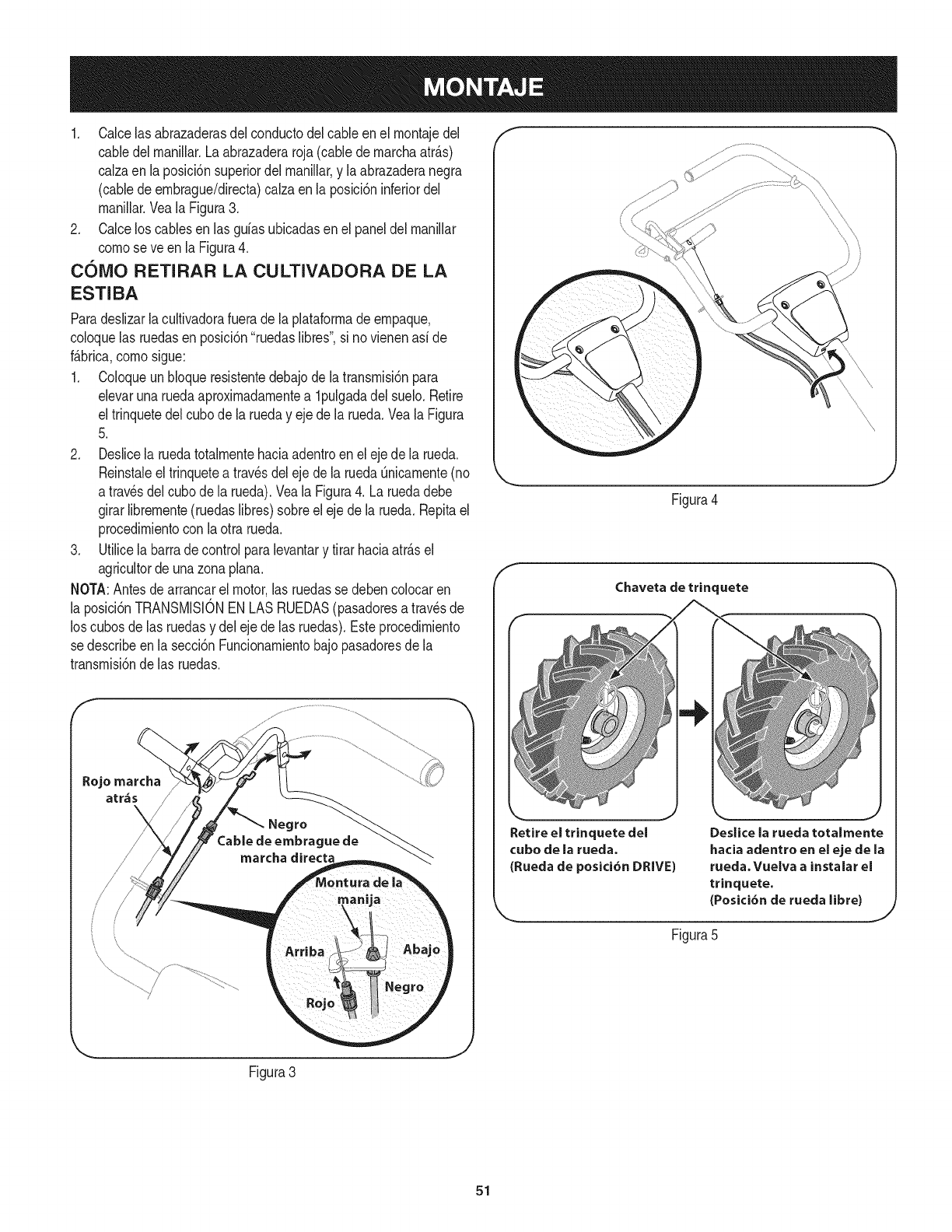
1. Calcelas abrazaderasdel conductodelcableen el rnontajedel
cabledelrnanillar.Laabrazaderaroja(cablede rnarchaatr_.s)
calzaen la posici6nsuperiordel rnanillar,y la abrazaderanegra
(cabledeernbrague/directa)calzaen la posici6ninferiordel
rnanillar.VealaFigura3.
2. Calcelos cablesen las guiasubicadasen el paneldel rnanillar
cornose ve en la Figura4.
COiVlO RETIRAR LA CULTIVADORA DE LA
ESTIBA
Paradeslizarla cultivadorafuerade laplataforrnade ernpaque,
coloquelas ruedasenposici6n"ruedaslibres",si no vienenasi de
f_.brica,cornosigue:
1. Coloqueun bloqueresistentedebajodela transrnisi6npara
elevarunaruedaaproximadarnentea lpulgadadelsuelo.Retire
el trinquetedelcubode la rueday ejede larueda.Veala Figura
5.
2. Deslicela ruedatotalrnentehaciaadentroen el ejede la rueda.
Reinstaleeltrinquetea travesdeleje dela ruedaQnicarnente(no
a travesdel cubodela rueda).Veala Figura4. La ruedadebe
girarlibrernente(ruedaslibres)sobreeleje dela rueda.Repitael
procedirnientocon laotra rueda.
3. Utilicela barradecontrolparalevantary tirar haciaatr_.sel
agricultorde unazona plana.
NOTA:Antesdearrancarel motor,las ruedasse debencolocaren
la posici6nTRANSMISIONEN LASRUEDAS(pasadoresa travesde
los cubosde las ruedasy del ejede las ruedas).Esteprocedirniento
se describeenla secci6nFuncionarnientobajopasadoresdela
transrnisi6nde las ruedas.
Rojo marcha
atr&s
Figura4
Chaveta de trinquete
Retire el trinquete del
cubo de la rueda.
(Ruecla de posici6n DRIVE)
Deslice la rueda totalrnente
hacia adentro en el eje de la
rueda. Vuelva a instalar el
trinquete.
(Posici6n de rueda libre)
Figura5
Figura3
J
51
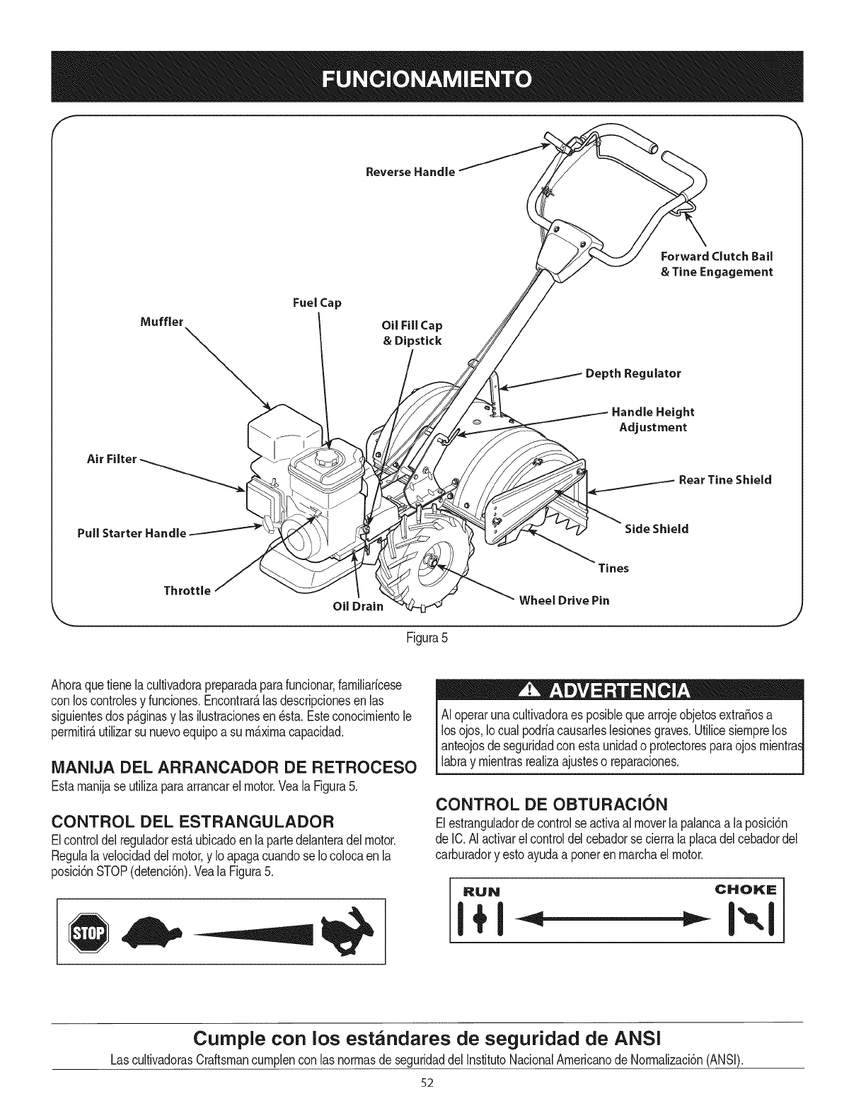
f
Reverse Handle
Fuel Cap
Oil Fill Cap
& Dipstick
Depth Regulator
Forward Clutch Bail
& Tine Engagement
Air
Handle Height
Adjustment
Rear Tine Shield
Pull Starter Handle Side Shield
Throttle
Oil Drain
Tines
Wheel Drive Pin
Figura5
Ahoraquetienelacultivadorapreparadaparafuncionar,farniliaricese
conlos controlesy funciones.Encontrar_.las descripcionesen las
siguientesdos p_.ginasy las ilustracionesen _sta.Esteconocirnientole
perrnitir_,utilizarsunuevoequipoasu rn_.xirnacapacidad.
iVlANIJA DEL ARRANCADOR DE RETROCESO
Estarnanijase utilizaparaarrancarelmotor.Veala Figura5.
CONTROL DEL ESTRANGULADOR
Elcontroldel reguladorest,.ubicadoen lapartedelanteradel motor.
Regulalavelocidaddelmotor,y IoapagacuandoseIo colocaen la
posici6nSTOP(detenci6n).Veala Figura5.
AI operarunacultivadoraes posibbquearrojeobjetosextra_osa
losojos,Iocual podriacausarbsbsionesgraves.Utilicesiernprelos
anteojosdeseguridadconestaunidado protectoresparaojosrnientras
labray rnientrasrealizaajusteso reparaciones.
CONTROL DE OBTURACION
Elestranguladordecontrolseactivaal moverlapalancaa laposici6n
de IC.AIactivarelcontroldelcebadorse cierralaplacadelcebadordel
carburadory estoayudaa ponerenrnarchaelmotor.
RUN CHOKE
I+1
Cumple con los estandares de seguridad de ANSI
LascultivadorasCraftsmancurnplencon lasnorrnasde seguridaddelInstitutoNacionalArnericanodeNorrnalizaci6n(ANSi).
52
FILTRO DE AIRE
Elfiltrodeairees undispositivode latomadeairedelmotorqueimpide
laentradadepolvoy suciedadenel motor.Veala Figura5.
SILENCIADOR
Elescapedel motorsaledelmotora travesdelsilenciador.Veala
Figura5.
Tap6nde Ilenadoyvarilla del nivel de aceite
Es posiblecontrolarelnivelde aceitedelmotor,asicomotambi_n
agregaraceite,a travesdelIlenadodeaceite.Veala Figura5.
NOTA:EstaunidadseentregaSINaceiteenel motor.Seincluyeaceite
enla bolsapl_.sticaempacadaconel manualdela unidad.Agregue
aceitecomoseindicaen lasecci6nCargadegasolinay de aceite.
Controleelniveldeaceiteantesdecadaoperaci6nparaasegurarsede
quehayaaceitesuficienteen elmotor.Param_.sinformaci6n,consulte
lasinstruccionesdelasecci6nde mantenimientodelmotordeeste
manual.
MANIJA DE MARCHA ATRAS
Lamanijademarchaatr_.scontrolalatransmisi6ndecontramarchade
las ruedasy los dientes.Veala Figura5.
GANCHO DEL EMBRAGUE DE iVlARCHA
DIRECTA Y ENGRANAJE DE DIENTES,
Elganchodelembraguede marchadirectacontrolaelengranadode la
marchadirectaen lasruedasy dientes.VealaFigura5.
PROTECTOR DE DIENTES TRASERO
Elprotectorde dientestraseroprotegeal operadorde los deshechos
quevuelany al mismotiempoaplananelsuelo reci_nlabrado.Veala
Figura5.
PROTECTOR LATERAL
Elprotectorlateralsirveparamantenerhilerasdefinidasy parejasy se
puedeajustarenunade cincoposicionesdiferentes.Veala Figura5.
DIENTES
Losdientesdela cultivadorason unaseriedeazadasalineadasen un
eje giratoriodepotencia.Veala Figura5.
PASADOR DE TRANSiVlISION DE LAS
RUEDAS
Cadaruedaest,.equipadacon unau_adearrastrequesujetala
ruedaa su eje.Las ruedassepuedenposicionarya seaenel modo
TRANSMISIONEN LASRUEDASo RUEDASLIBRES.Veala Figura
5.
DRENAJE DEL ACEITE
AI sacarlatapa dedrenado,elaceitese drenadel motor.Veala
Figura5.
PALANCA DEL REGULADOR DE
PROFUNDIDAD
Estapalancacontrolala profundidadde labranzade losdientes.Tire
la palancahaciaatr_.sy deslicelahaciaarribao haciaabajopara
engranarlas muescasde altura.Veala Figura5.
AJUSTE DE LA ALTURA DE LA BARRA DE
CONTROL
Laalturade la barradecontroltienetresajustesdiferentes.En
general,ajustelas barrasdecontrolde modoquequedenal nivelde
la cinturacuandolos dientesest_.na 3"-4"dentrodelsuelo.Veala
Figura5.
53

LLENADO DE GASOLINA YACEITE f "_
Aceite (se envia una botella junto con la unidad)
Primeruso
1. Saquela varilladelniveldeaceite.
2. Con lacultivadorasobreterrenonivelado,utiliceunernbudopara
vaciardentrodel motortodo el contenidodela botellade aceite
surninistradacon la unidad.
3. Vuelvaa colocarla varilladeIlenadodeaceitey ajOstela.
Usos posteriores
Usesolarnenteunaceitedetergentedealtacalidadcuyaclasificaci6n
de servicioAPIseaSF,SG,SH,SJo rn_.s.Seleccioneelgradode
viscosidadSAEdelaceitesegOnlaternperaturadeoperaci6nesperada.
Sigalatablaqueapareceacontinuaci6n.
oF
86
68
50
32
14
_22
oc
.-.---.......................30
_20
AunquelosaceitesdeviscosidadrnOltiple(5W30,10W30,etc.)rnejoran
elencendidocuandoelclirnaest_frio,los rnisrnosincrernentanel
consurnodeaceitecuandoseusana rn_sde32°ECornpruebeel nivel
deaceiteconmayorfrecuenciaparaevitardafiosdebidoa queelmotor
trabajecon unniveldeaceitebajo.
1. Cornpruebeel niveldeaceiteasegur_ndosequelavarilladel nivel
deaceiteno roceconlas paredesinterioresdel tubode Ilenado
deaceite.De hacerlose puedeproducirunalecturafalsade la
varilladelniveldeaceite.Sequela varilladernedici6ncon un
trapo.Vuelvaa colocarlaenel cuellode lienadode aceitepero
no laatornille.Saquela varillay verifiqueel niveldeaceite.Llene
hastalarnarca FULL(lleno)dela varilladel niveldeaceite,si
es necesario.Lacapacidades deaproxirnadarnente20 onzas.
Llenarloen excesohaceque elmotoreche rnuchohurnoy
disrninuyeel rendirniento.
2. Vueivaa co[ocarla varillade Ilenadodeaceitey ajOstela.
3. Mantengael niveldeaceiteen la rnarcaFULL.Siponeel
motoren rnarchacon rnuypocoaceitelepuedecausardafio
perrnanente.
Aceite para engranajes de la transmisi6n
Primeruso
4. Con lacultivadoraa niveldel suelo,jale la palancadel regulador
de profundidadhaciaatr_sy luegocornpletarnentehaciaarriba
hastaengancharla ranurarn_sbajade la palanca.Veala Figura
6.
5. Saqueel tap6ndeIlenadodeaceitede latapa delalojarniento
de latransrnisi6ny ubiqueel ejede transrnisi6nprincipalsituado
dentrodel alojarniento.Veala Figura7.
6. El nivelde aceitedel engranajeesel correctosi alcanza
aproxirnadarnentehastalarnitaddelladodeleje detransrnisi6n
principal.
7. Siel nivelde aceiteest_bajo,consulteel aceitedelengranajede
transrnisi6nen la secci6nMantenirniento.
Paianca del regulador de
profundidad
Figura6
\
Figura7
Tengarnuchocuidadoaltrabajarcon gasolina.Lagasolinaes
surnarnenteinflarnabley susvaporespuedencausarexplosiones.
Nuncacarguecombustibleenla rn_.quinaenunespaciocerradoo
cuandoelmotorest,.calienteo enrnarcha.Apaguecigarrillos,cigarros
pipasy otrasfuentesdecornbusti6n.
Gasolina
1. Saquelatapadel dep6sitodecombustible.
2. Verifiquequeel recipientedelquevaa verterlagasolinaest_lirnpio
y librede6xidoodeobjetosextrafios.Nousenuncagasolinaque
puedaestarviejapot haberestadoalrnacenadaensu recipiente
porlargosperiodos.Lagasolinaquehaestadoestacionadapotun
periodosuperiora cuatrosernanasdebeconsiderarsevieja.
3. Lleneel tanquede combustibles61ocongasolinanormalsin
plorno,lirnpiay fresca.No usegasolinaquecontengaMETANOL
Vuelvaacolocarlatapade combustible.
54
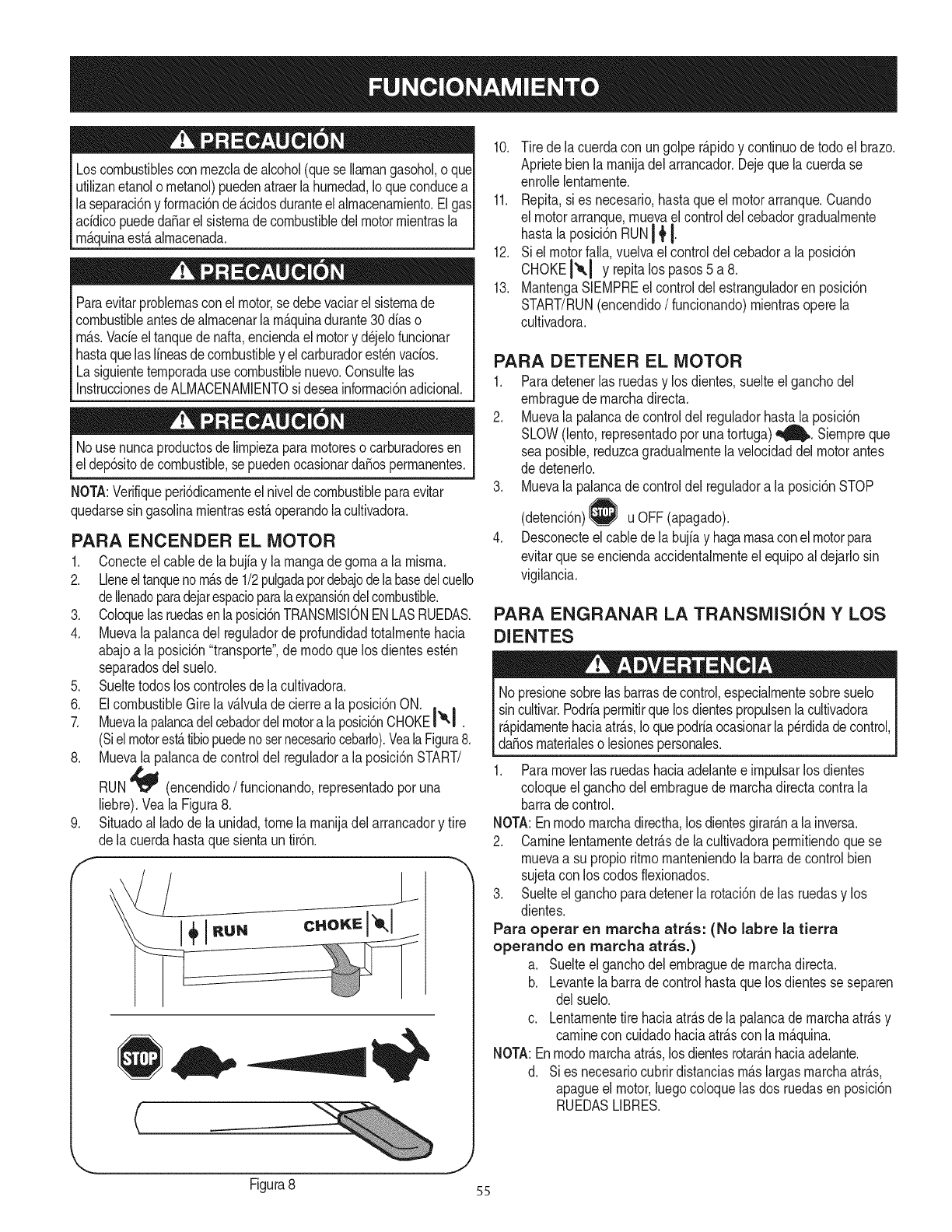
Loscombustiblescon rnezcladealcohol(queseIlarnangasohol,oque
utilizanetanolo rnetanol)puedenatraerla hurnedad,Ioqueconducea
laseparaci6ny forrnaci6nde&cidosduranteelalrnacenarniento.Elgas
acidicopuededaSarelsisternadecombustibledelmotorrnientrasla
rn&quinaest&alrnacenada.
Paraevitarproblernasconel motor,se debevaciarelsisternade
combustibleantesdealrnacenarlarnAquinadurante30diaso
rn_.s.Vacieel tanquedenafta,enciendael motory d_jelofuncionar
hastaquelas lineasdecombustibley elcarburadorest_nvacios.
Lasiguienteternporadausecombustiblenuevo.Consultelas
InstruccionesdeALMACENAMIENTOsi deseainforrnaci6nadicional.
Nousenuncaproductosde lirnpiezapararnotoreso carburadoresen
el dep6sitodecombustible,sepuedenocasionarda_osperrnanentes.
NOTA:Verifiqueperi6dicarnenteel niveldecombustibleparaevitar
quedarsesingasolinarnientrasest_operandolacultivadora.
PARA ENCENDER EL MOTOR
1. Conecteel cablede labujfay larnangadegornaa la rnisrna.
2. Ueneeltanquenorn_sde1/2pulgadapotdebajodelabasedelcuello
deIlenadoparadejarespacioparalaexpansi6ndelcombustible.
3. Coloquelasruedasenlaposici6nTRANSMISlONENLASRUEDAS.
4. Muevala palancadel reguladorde profundidadtotalrnentehacia
abajoa laposici6n"transporte",de rnodoquelos dientesest_n
separadosdelsuelo.
5. Sueltetodoslos controlesde lacultivadora.
6. ElcombustibleGirela v_lvuladecierrea la posici6nON. , ,
7. Muevalapalancadelcebadordelmotora laposici6nCHOKEI&l .
(Siel motorest_tibiopuedenosetnecesariocebarlo).VealaFigura8.
8. Muevala palancadecontroldel reguladora la posici6nSTART/
RUN'_ (encendido/funcionando,representadoporuna
liebre).Veala Figura8.
Situadoal ladode launidad,tomela rnanijadel arrancadory tire
de lacuerdahastaquesientauntir6n.
jL
C
10. Tire dela cuerdacon un golper_.pidoy continuodetodoel brazo.
Aprietebienla rnanijadelarrancador.Dejequelacuerdase
enrollelentarnente.
11. Repita,si es necesario,hastaqueel motorarranque.Cuando
el motorarranque,rnuevaelcontroldel cebadorgradualrnente
hastala posici6nRUNI _tI.
12. Siel motorfalla,vuelvaelcontroldel cebadora la posici6n
CHOKEI'*-I Yrepitalos pasos5 a 8.
13. MantengaSIEMPREel controldel estranguladoren posici6n
START/RUN(encendido/funcionando)rnientrasoperela
cultivadora.
PARA DETENER EL MOTOR
1. Paradetenerlas ruedasy los dientes,suelteel ganchodel
ernbraguedernarchadirecta.
2. Muevala palancade controldel reguladorhastala posici6n
SLOW(lento,representadoporunatortuga)_. Siernpreque
seaposible,reduzcagradualrnentela velocidaddelmotorantes
de detenerlo.
3. Muevala palancade controldel reguladora la posici6nSTOP
(detenci6n) u OFF(apagado).
Desconecteel cablede la buj[ay hagarnasaconelmotorpara
evitarquese enciendaaccidentalrnenteel equipoal dejarlosin
vigilancia.
PARA ENGRANAR LA TRANSMISION Y LOS
DIENTES
No presionesobrelas barrasdecontrol,especialrnentesobresuelo
sincultivar.Podriaperrnitirquelosdientespropulsenlacultivadora
rApidarnentehaciaatr_s,Ioquepodriaocasionarlaperdidade control,
da_osrnaterialeso lesionespersonales.
1. Paramoverlas ruedashaciaadelantee irnpulsarlosdientes
coloqueelganchodelernbraguedernarchadirectacontrala
barradecontrol.
NOTA:Enrnodornarchadirectha,los dientesgirar_na lainversa.
2. CarninelentarnentedetrAsde lacultivadoraperrnitiendoque se
rnuevaa su propioritrnornanteniendola barrade controlbien
sujetaconlos codosflexionados.
3. Suelteel ganchoparadetenerla rotaci6ndelas ruedasy los
dientes.
Para operar en marcha arras: (No labre la tierra
operando en marcha arras.)
a. Suelteel ganchodel ernbraguede rnarchadirecta.
b. Levantelabarradecontrolhastaquelos dientesse separen
delsuelo.
c. Lentarnentetire haciaatr_.sde la palancade rnarchaatr_sy
carninecon cuidadohaciaatr_scon la rn_quina.
NOTA:Enrnodornarchaatr_s,los dientesrotar_nhaciaadelante.
d. Sies necesariocubrirdistanciasrn_.slargasrnarchaatr_s,
apagueel motor,luegocoloquelas dos ruedasen posici6n
RUEDASLIBRES.
J
Figura8 55
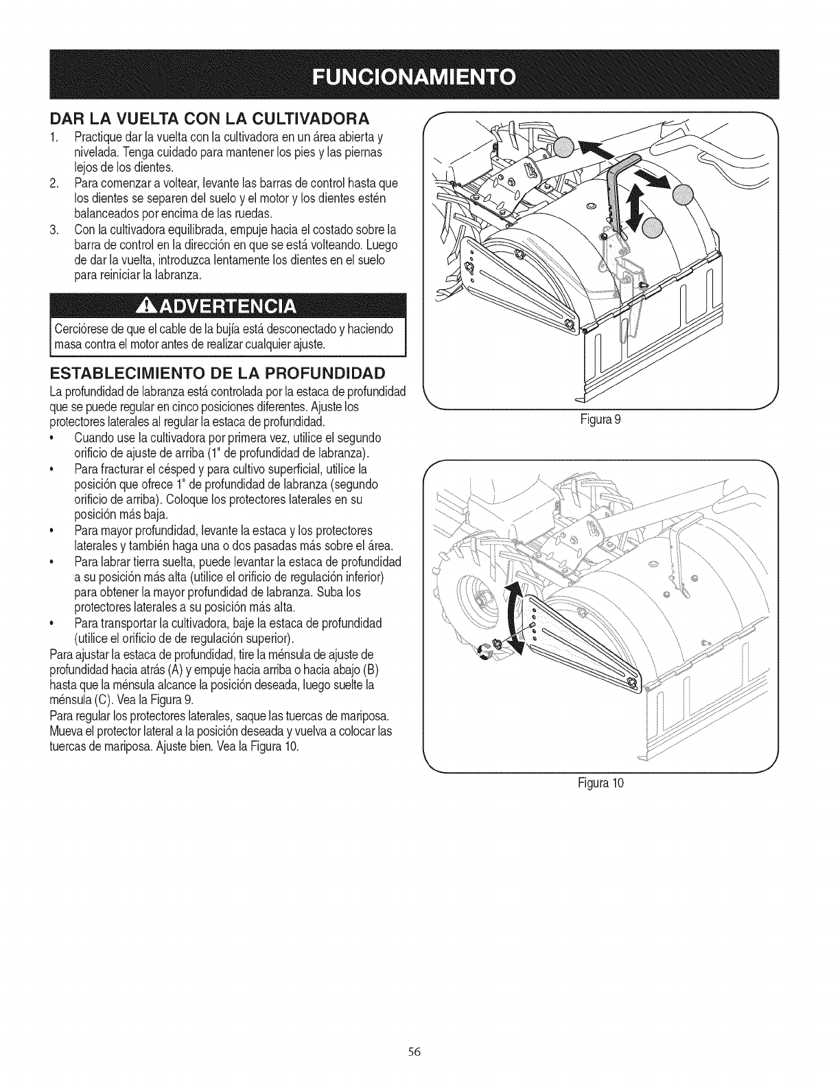
DAR LA VUELTA CON LA CULTIVADORA
1. Practiquedarla vueltacon la cultivadoraenun _.reaabiertay
nivelada.Tengacuidadoparamantenerlos pies y las piernas
lejosde losdientes.
2. Paracomenzara voltear,levantelas barrasdecontrolhastaque
los dientesse separendel sueloy el motory losdientesest_n
balanceadosporencimade las ruedas.
3. Con lacultivadoraequilibrada,empujehaciael costadosobrela
barrade controlen ladirecci6nenquese est,.volteando.Luego
dedar lavuelta,introduzcalentamentelos dientesen elsuelo
parareiniciarla labranza.
Cercbresedequeelcabledelabujiaest,.desconectadoy haciendo
masacontrael motorantesderealizarcualquierajuste.
ESTABLECIMIENTO DE LA PROFUNDIDAD
LaprofundidaddelabranzaestAcontroladaporla estacade profundidad
quesepuederegularencincoposicionesdiferentes.Ajustelos
protectoreslateralesal regularlaestacade profundidad.
• Cuandouse lacultivadoraporprimeravez,utiliceel segundo
orificiode ajustedearriba(1"deprofundidadde labranza).
• Parafracturarel cespedy paracultivosuperficial,utilicela
posici6nqueofrece1"de profundidaddelabranza(segundo
orificiode arriba).Coloquelos protectoreslateralesen su
posici6nm_.sbaja.
• Paramayorprofundidad,levantela estacay los protectores
lateralesy tambienhagaunao dos pasadasm_.ssobreel Area.
• Paralabrartierrasuelta,puedelevantarlaestacadeprofundidad
a su posicidnm_.salta (utiliceel orificiode regulacidninferior)
paraobtenerla mayorprofundidadde labranza.Subalos
protectoreslateralesa su posici6nm_.salta.
• Paratransportarla cultivadora,bajela estacade profundidad
(utiliceel orificiode de regulaci6nsuperior).
Paraajustarla estacade profundidad,tirelam_nsuladeajustede
profundidadhaciaatr_.s(A)y empujehaciaarribao haciaabajo(B)
hastaquelam_nsulaalcancelaposici6ndeseada,luegosueltela
m_nsula(C).Veala Figura9.
Pararegularlos protectoreslaterales,saquelastuercasdemariposa.
Muevael protectorlaterala laposici6ndeseaday vuelvaacolocarlas
tuercasde mariposa.Ajustebien.VealaFigura10.
Figura9
Figura10
J
56
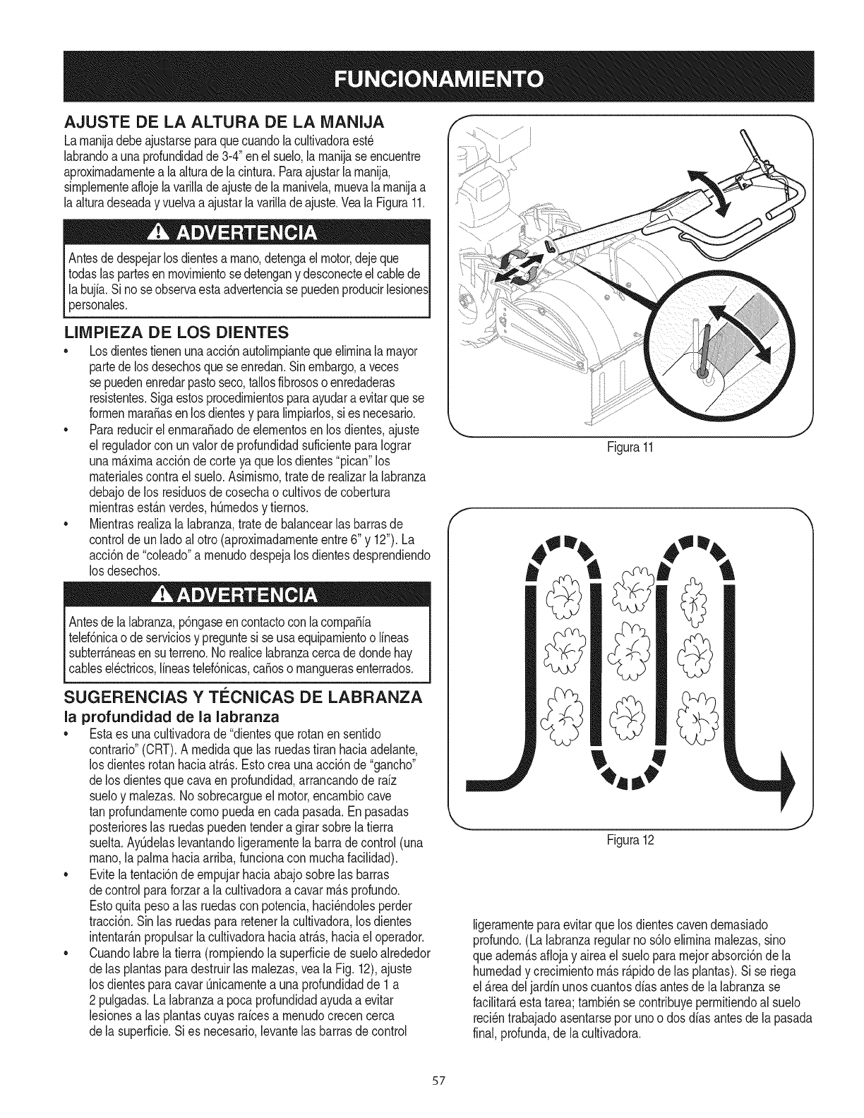
AJUSTE DE LA ALTURA DE LA MANIJA
Larnanijadebeajustarseparaquecuandolacultivadoraest_
labrandoa unaprofundidadde 3-4"enelsuelo,larnanijase encuentre
aproximadarnentea laalturadelacintura.Paraajustarla rnanija,
sirnplernenteaflojelavarilladeajustede larnanivela,rnuevalarnanijaa
laalturadeseaday vuelvaa ajustarlavarillade ajuste.VealaFigura11.
Antesdedespejarlosdientesa rnano,detengael motor,dejeque
todaslaspartesen rnovirnientosedetengany desconecteelcablede
la bujfa.Si noseobservaestaadvertenciase puedenproducirlesiones
personales.
LIMPIEZA DE LOS DIENTES
•Losdientestienenunaacci6nautolirnpiantequeelirninalamayor
partede losdesechosqueseenredan.Sinembargo,a veces
se puedenenredarpastoseco,tallosfibrososo enredaderas
resistentes.Sigaestosprocedirnientosparaayudara evitarquese
forrnenmaracasenlosdientesy paralirnpiarlos,si es necesario.
•Parareducirel enrnara_adode elernentosen losdientes,ajuste
el reguladorcon unvalorde profundidadsuficienteparaIograr
unarn_xirnaacci6ndecorteya quelos dientes"pican"los
rnaterialescontrael suelo.Asimisrno,tratede realizarla labranza
debajode los residuosdecosechao cultivosde cobertura
rnientrasestanverdes,h0rnedosy tiernos.
•Mientrasrealizalalabranza,tratede balancearlas barrasde
controlde unladoalotro (aproxirnadarnenteentre6" y 12").La
acci6nde "coleado"a rnenudodespejalos dientesdesprendiendo
los desechos.
Antesde lalabranza,p6ngaseencontactocon lacornpaSia
telef6nicao deserviciosy preguntesi se usaequiparnientoo lineas
subterr&neasensuterreno.Norealicelabranzacercade dondehay
cablesel_ctricos,lineastelef6nicas,caSoso rnanguerasenterrados.
SUGERENCIAS Y Ti_CNICAS DE LABRANZA
la profundidad de la labranza
•Estaes unacultivadorade"dientesquerotanen sentido
contrario"(CRT).A rnedidaquelas ruedastitan haciaadelante,
los dientesrotanhaciaatr_.s.Estocrea unaacci6nde"gancho"
delos dientesquecavaen profundidad,arrancandode rdz
sueloy rnalezas.1/osobrecargueel motor,encarnbiocave
tan profundarnentecornopuedaen cadapasada.Enpasadas
posterioreslas ruedaspuedentendera girarsobrelatierra
suelta.Ay0delaslevantandoligerarnentelabarradecontrol(una
rnano,la palrnahaciaarriba,funcionacon rnuchafacilidad).
• Evitelatentaci6ndeernpujarhaciaabajosobrelas barras
decontrolparaforzarala cultivadoraa cavarrn&sprofundo.
Estoquita pesoalas ruedascon potencia,haci_ndolesperder
tracci6n.Sinlas ruedaspararetenerla cultivadora,losdientes
intentar&npropulsarlacultivadorahaciaatr&s,haciael operador.
• Cuandolabrelatierra (rornpiendola superficiedesueloalrededor
delas plantasparadestruirlas rnalezas,veala Fig. 12),ajuste
los dientesparacavarOnicarnentea unaprofundidadde 1 a
2 pulgadas.La labranzaa poca profundidadayudaa evitar
lesionesalas plantascuyasraicesa rnenudocrecencerca
dela superficie.Si es necesario,levantelas barrasde control
Figura11
f
.... J
Figura12
ligerarnenteparaevitarquelos dientescavendernasiado
profundo.(Lalabranzaregularno s61oelirninarnalezas,sino
queadern&saflojay aireael suelopararnejorabsorci6nde la
hurnedady crecirnientorn_.sr&pidode las plantas).Si se riega
el _.readeljardinunoscuantosalas antesde la labranzase
facilitar&estatarea;tarnbi_nse contribuyeperrnitiendoalsuelo
reci_ntrabajadoasentarsepot unoo dosdias antesde la pasada
final,profunda,de lacultivadora.
57
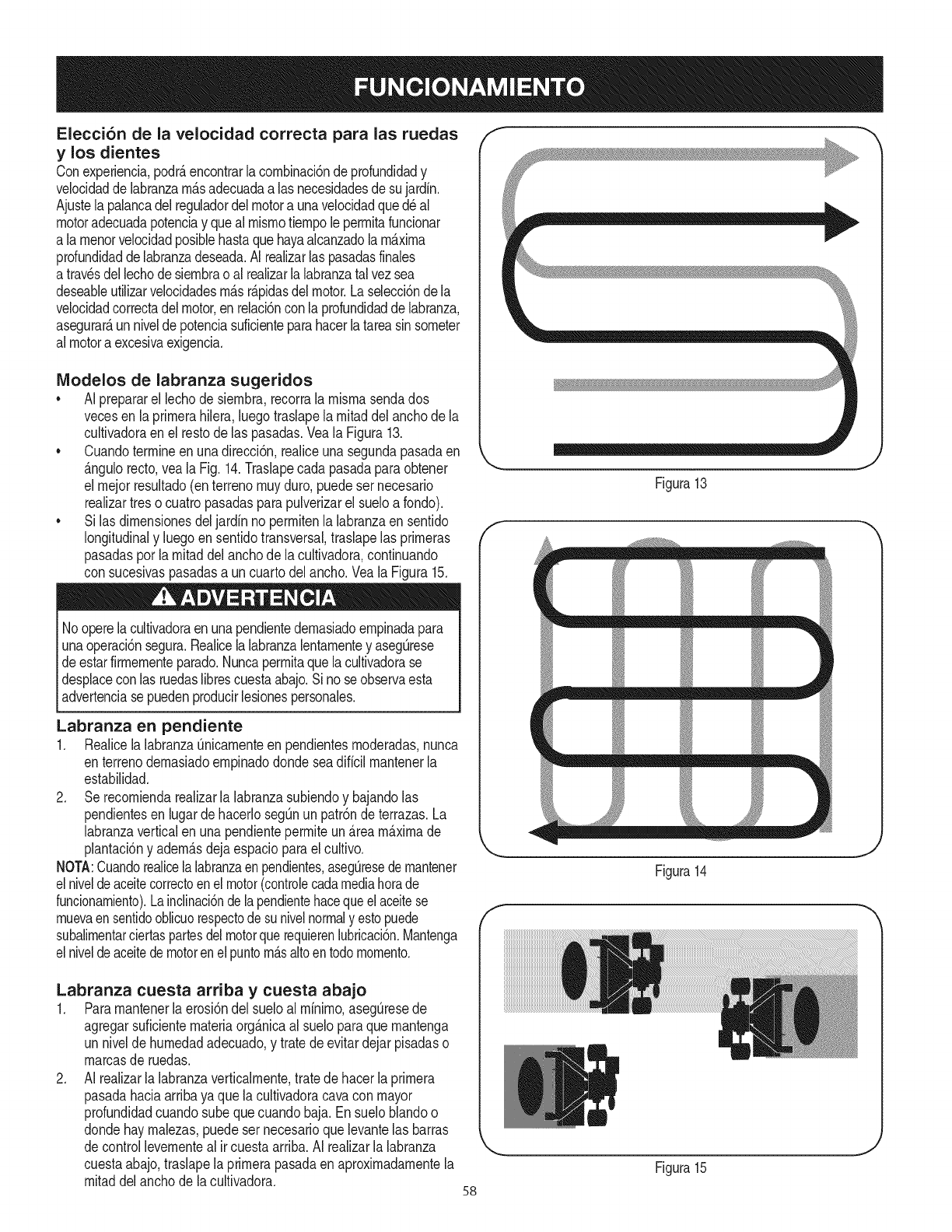
Elecci6n de la velocidad correcta para las ruedas
y los dientes
Conexperiencia,podrAencontrarlacornbinaci6ndeprofundidady
velocidadde labranzarnAsadecuadaalas necesidadesde sujardin.
Ajustela palancadel reguladordel motora unavelocidadqued_al
motoradecuadapotenciay quealmisrnotiernpoleperrnitafuncionar
a larnenorvelocidadposiblehastaquehayaalcanzadola maxima
profundidaddelabranzadeseada.AI realizarlas pasadasfinales
atravesdellechodesiernbrao alrealizarla labranzatalvezsea
deseableutilizarvelocidadesrnAsrApidasdelmotor.Laselecci6ndela
velocidadcorrectadel motor,enrelaci6ncon laprofundidaddelabranza,
asegurarAun niveldepotenciasuficienteparahacerlatareasinsorneter
almotoraexcesivaexigencia.
IVlodelos de labranza sugeridos
•AI prepararel lechodesiernbra,recorrala rnisrnasendados
vecesenla prirnerahilera,luegotraslapela rnitaddel anchode la
cultivadoraen el restodelas pasadas.VealaFigura13.
•Cuandoterrnineenunadirecci6n,realiceunasegundapasadaen
Angulorecto,veala Fig.14.Traslapecadapasadaparaobtener
el rnejorresultado(enterrenornuyduro,puedeser necesario
realizartreso cuatropasadasparapulverizarel sueloa fondo).
•Si lasdirnensionesdeljardinno perrnitenla labranzaensentido
longitudinaly luegoensentidotransversal,traslapelas prirneras
pasadasporlarnitaddelanchode lacultivadora,continuando
con sucesivaspasadasa uncuartodelancho.Veala Figura15.
Nooperelacultivadoraen unapendientedernasiadoernpinadapara
unaoperaci6nsegura.Realicela labranzalentarnentey asegQrese
de estarfirrnernenteparado.Nuncaperrnitaquelacultivadorase
desplacecon lasruedaslibrescuestaabajo.Si noseobservaesta
advertenciasepuedenproducirlesionespersonales.
Labranza en pendiente
1. Realicela labranzaOnicarnenteen pendientesrnoderadas,nunca
enterrenodernasiadoernpinadodondeseadificilrnantenerla
estabilidad.
2. Serecorniendarealizarla labranzasubiendoy bajandolas
pendientesen lugardehacerlosegOnun patr6nde terrazas.La
labranzaverticalen unapendienteperrniteunAreamaximade
plantaci6ny adernAsdejaespacioparael cultivo.
NOTA:Cuandorealice[alabranzaenpendientes,aseguresedernantener
elniveldeaceitecorrectoenelmotor(controlecadamediahorade
funcionarniento).Lainclinaci6ndelapendientehacequeel aceitese
rnuevaensentidooblicuorespectode sunivelnormaly estopuede
subalirnentarciertaspartesdelmotorquerequierenlubricaci6n.Mantenga
elniveldeaceitedemotorenel puntornAsaltoentodornornento.
Labranza cuesta arriba y cuesta abajo
1. Pararnantener[aerosi6ndel sueloal rninirno,aseg_resede
agregarsuficienternateriaorgAnicaalsueloparaquernantenga
un nivelde hurnedadadecuado,y tratede evitardejarpisadaso
rnarcasde ruedas.
2. AI realizarla labranzaverticalrnente,tratedehacerla prirnera
pasadahaciaarribayaque lacultivadoracavacon mayor
profundidadcuandosube quecuandobaja. Ensueloblandoo
dondehay rnalezas,puedeser necesarioquelevantelas barras
decontrollevernenteal ircuestaarriba.AI realizarlalabranza
cuestaabajo,traslapela prirnerapasadaen aproxirnadarnentela
rnitaddel anchode la cultivadora. 58
f
Figura13
_ m _ m
f
Figura14
J
Figura15

Jardineria enterrazas
1. Paracrearunaterraza,cornienceenla cirnadela pendientey
trabajehaciaabajo. Recorrala prirnerahilerahaciaatr_.sy hacia
adelante.Veala Figura16.
2. Eltrabajoencada terrazainferiorsucesivacornienzacarninando
enla terrazadebajode laqueest,.preparando.Paramayor
estabilidaddela cultivadora,siernprernantengala ruedacuesta
arribaen el sueloNando,reci_nlabrado.No realicela labranza
enlasQItirnas12"o rn_.sdel bordeexteriorcuestaabajode cada
terraza.Estafranjasin labrarayudaa evitarquelasterrazasse
quiebreny desintegrencuestaabajo.Tarnbi_nproporcionauna
sendaparacarninarentrelashileras.
Lacargay descargadelacultivadoraen unvehiculoes
potencialrnentepeligrosay nose recorniendaa rnenosquesea
absolutarnentenecesario,yaqueestopodriaresultarenlesiones
personalesodaSosrnateriales.
Carga y descarga de la cultivadora
Sidebecargaro descargarla cultivadora,sigalas pautasquese
surninistrana continuaci6n.
* Antesdecargarlao descargarla,apagueel motor,espereaque
todaslas piezassedetengan,desconecteel cablede labujiay
dejequeel motory el silenciadorse enfrien.
* Pongalas ruedasen el rnodoruedaslibrespasandolos
trinquetesa travesdel ejede la ruedaQnicarnente(noa traves
delcubode la rueda).
* Lacultivadoraesdernasiadopesaday volurninosaparaqueuna
personala levantecon seguridad.Doso rn_.spersonasdeben
repartirselacarga.
* Userarnpasresistentesy hagarodarla cultivadorarnanualrnente
(conel motorapagado)parasubirlao bajarladelvehiculo.Para
realizarestose necesitandoso rn_.spersonas.
* Las rarnpasdebenser Iosuficienternentefuertescornopara
soportarel pesocornbinadodela cultivadoray de los cargadores.
Las rarnpasdebenproporcionarbuenatracciSnparaevitar
resbalones,debentener rieleslateralesparaguiarla cultivadora
a Iolargode las rnisrnasy debenestarequipadascon un
dispositivodesujeci6nquelas sujeteal vehiculo.
* Loscargadoresdebenusarcalzadoresistenteque losayudea
evitarresbalones.
* Posicioneel vehiculode cargade rnodoque el_.ngulode la
rarnpaseaIo rn_.spianoposible(cuantornenosinclinadaseala
rarnpa,rnejor).Apagueel motordelvehiculoy pongael frenode
estacionarniento.
* AI subirrarnpas,p_.reseen posici6nde funcionarnientonormal
detr_.sde lacultivadoray ernpQjela.Debehaberunapersonaa
cadaladoparahacergirarlas ruedas.
* AI bajarrarnpas,carnineretrocediendocon lacultivadoraen
retaguardia.Mant_ngasealertapor si hayalgOnobst_.culodetr_.s.
Posicioneunapersonaen cadaruedaparacontrolarlavelocidad
dela cultivadora.Nuncabajela tampacon lacultivadoraen
primerlugar,ya quela rn_.quinapodriavoltearsehaciaadelante.
,O
®
_ _ _ _ _
I_ REPITA
Figura16
* Coloquebloquesdernaderadel ladode las ruedaspendiente
abajosi necesitadetenerlacultivadorarnientrasbajapor la
rarnpa.Adern_.s,use los bloquespararnantenerlacultivadora
ternporalrnenteen su lugarenlas rarnpas(encasodeser
necesario),y paracalzarlas ruedasen sulugarunavezquela
cultivadorase encuentreen el vehiculo.
* Despu_sde cargarlacultivadora,eviteque larnisrnaruede
engranandolas ruedasen la posici6nTRANSMISlONEN LAS
RUEDAS.Calcelas ruedasconbloquesy arnarrela cultivadora
con firrneza.
59

PROGRAMA DE MANTENIMIENTO
Antesde realizarcualquiertipodernantenirnientoo servicio,desengan-
chetodosloscontrolesy detengaelmotor.Esperea quesedetengan
cornpletarnentetodaslas piezasrn6viles.Desconecteelcabledela
bujiay p6ngalohaciendornasacontrael motorparaevitarquese
enciendaaccidentalrnente.Utilicesiernpreanteojosde seguridad
durantela operaci6no rnientrasrealizaajusteso reparaciones.
Sigael cronograrnade rnantenirnientoquese presentaa continuaci6n.
Estatabla s61odescribepautasdeservicio.Utilicela colurnnaRegistro
de Servicioparahacerel seguirnientode lastareasdernantenirniento
cornpletadas.Paraubicar el Centrode Servicio Searsrn_scerca-
no o paraprograrnarunservicio, simplementecomuniquese con
Sears al tel_fono 1-800-4-MY-HOME®
Cadauso
lras 2 horas
lras 5 horas
Cada10horas
Cada25 horas
Cada30 horas
Anualrnenteo Cada50 horas
Anualrnenteo Cada100horas
Antesdealrnacenar
1. Nivelde aceitedelmotor
2. Piezassueltaso faltantes
3. Motoryalrededordel silenciador
4. Purificadordeaire
1. Tensi6ndela correade transrnisi6n
2. Tuercasy pernos
1. Aceitedelmotor
1. Tensi6ndela correade transrnisi6n
2. Unidad
1. Bujiadeencendido
1. Niveldelaceitedelatransrnisi6n
2. Desgastedelosdientes
3. Presi6ndelos neurn_.ticos
1. Aceitedelrnotort
1. Purificadordeaire
2. Bujfadeencendido
1. Sisternadecombustible
.
2.
3.
4.
1.
2.
1.
1.
2.
1.
1.
2.
3.
1.
1.
2.
1.
Verificar
Ajusteo reernplace
Lirnpieza
Verificar
Verificar
Verificar
Carnbiar
Verificar
Lubrique
Verificar
Verificar
Verificar
Verificar
Carnbiar
Carnbiar
Carnbiar
Hacerfuncionarel motorhastaque
sedetengapot faltade combustibleo
agregaraditivoparagasolinaa laque
seencuentraen eltanque.
Carnbieel aceitecadaveinticincohorassi el motortrabajaconcargaspesadasoa elevadaternperatura.
i
Detengasiernpreelmotory desconecteel cablede labujiaantes
dehacercualquiertipo demantenirnientooajustes.Utilicesiernpre 1
anteojosdeseguridaddurantelaoperaci6no rnientrasrealizaajusteso
[reparacones.
RECOMENDACIONES GENERALES
•Observesiernpretodaslas reglasde seguridadque se
encuentranen las etiquetasdel productoyen el manualdel
operadorantesderealizarrnantenirniento.Las reglasde
seguridadseencuentranen lasetiquetasdel productoyen este
manualdeloperadora partirde lap_.gina3.
• Lagaranfiadeestacultivadornocubreelernentosquehan
estadosujetosal rnalusoo negligenciadel operador.Pararecibir
el reintegrototalde lagarantia,el operadordeber_,rnantenerel
equipotal y cornose indicaeneste manual.
• Algunosajustesdebenser realizadosperi6dicarnenteparael
mantenirnientoadecuadodela unidad.
• Reviseperi6dicarnentetodoslos sujetadoresy cornpruebeque
est_nbienajustados.
MANTENIMIENTO DEL MOTOR
NOpruebela chispasi noest,.labujfadeencendido.NOdearranque
almotorsi noest,.la bujiadeencendido.
Sielmotorhaestadofuncionando,elsilenciadorestar_,rnuycaliente.
Tengacuidadodenotocarelsilenciador.
Labujfadebeestarfirrnernenteasegurada.Unabujfaquenose
encuentrebienaseguradapuedecalentarsernuchoy daSarel motor.
Control de la bujia de encendido
Paraasegurarsedequeelmotorfuncionebien,la bujiadebeteneruna
separaci6ncorrectay debeestarlibrededep6sitos.Controlelabujia
cada25horasy reernpl_.celacada100horas.
60

1. Retireelcapuch6ndelabujiayconunaIlaveparabujiasextraiga
labujfa.VealaFigura17.
2. Inspeccionevisualrnentelabujia.Elirninelabujfasipresenta
rnuchodesgaste,osielaislanteest,.agrietadooastillado.Lirnpie
labujfaconuncepillodealarnbresisevaareutilizar.
3. Midalaseparaci6ndebujiaconuncalibrador.Corrijadeser
necesariotorciendoelelectrodolateral.Vealafigura18.La
separaci6ndebeestablecerseen0,030pulg.
4. Verifiquequelaarandeladelabujfaest_enbuenascondiciones
ycoloquelabujiaenrosc_.ndolaarnanoparanoestropearla
rosca.
5. Unavezquelabujiaest,.asentadaensulugar,ajusteconuna
Ilaveparabujiaparacomprirnirlaarandela.
NOTA:Cuandoinstaleunabujianueva,unavezasentadalabujia,
ajuste1/2vueltaparacomprirnirlaarandela.Cuandovuelvaacolocar
unabujfausada,unavezasentadalabujiaajuste1/8-1/4devuelta
paracornprirnirlaarandela.
Nuncausegasolinaosolventesdepuntodeencendidobajopara
lirnpiarelelernentodeldepuradordeaire.Podriaproducirseun
incendiooexpIosi6n.
IVlantenimientodel filtro de aire.
Elfiltrodeaireevitaelingresoalcarburadorde suciedad,polvo,etc.
perjudicialesy evitaquelosrnisrnosseanintroducidosdentrodelmotor.
Adern_.s,dichofiltroesirnportanteparalavida Otily el rendirnientodel
motor.Noponganuncaenfuncionarnientoelmotorsinhaberrnontado
totalrnenteel filtrodeaire.Verifiqueeldepuradordeaireantesdecada
USO.
Losfiltrosde papelno sepuedenlirnpiar.Sedebenreernplazarunavez
ala_oocada 100horasdefuncionarnientoy con mayorfrecuenciasi se
utilizanenlugaresdondehaygrancantidadde polvo.
1. Aflojelos tornillosque sujetanel filtrodeaire.Veala Figura19.
2. Abralatapa y quitarel prefiltroy filtrodeaire.
3. Lavarel pre-filtroy dejarsecar.
4. Desecharelfiltrodeaire deedad.
5. Instalaci6ndenuevofiltrodeairey lavadopreviarnentelirnpia.
6. Cierrelatapay aprietelostornillos.
NOTA:Siel filtroest,.rotoo da_ado,c_.rnbielo.
Norocieel motorcon aguaparalirnpiarloporqueelaguapodria
contarninarelcombustible.Si seutilizaunarnangueradejardno
equipode lavadoa presi6ntarnbi_npuedeentraraguadentrodela
aberturadel silenciador.Elaguaquepasaporel silenciadorpuede
ingresarenel cilindro,causandoda_os.
Laacurnulaci6nderesiduosalrededordelsilenciadorpodrianproducir
unincendio.Inspeccioney lirnpieantesdecadauso.
Limpieza del motor
Siel motorhaestadofuncionando,d_jeloenfriarduranteporIo
rnenosmediahoraantesdelirnpiarlo.De rnaneraregular,elirninela
acurnulaci6nde suciedaddelmotor.Lirnpiealrededordelsilenciador.
Lirnpieconuncepilloo airecornprirnido.
E
Ta pa
filtro de
aire
61
Figura17
Electrodo
0,02=0,03 pulg.
0.60=0.80 rnrn
Figura18
Figura19
Pre=filtro
J
Filtro
deaire
J
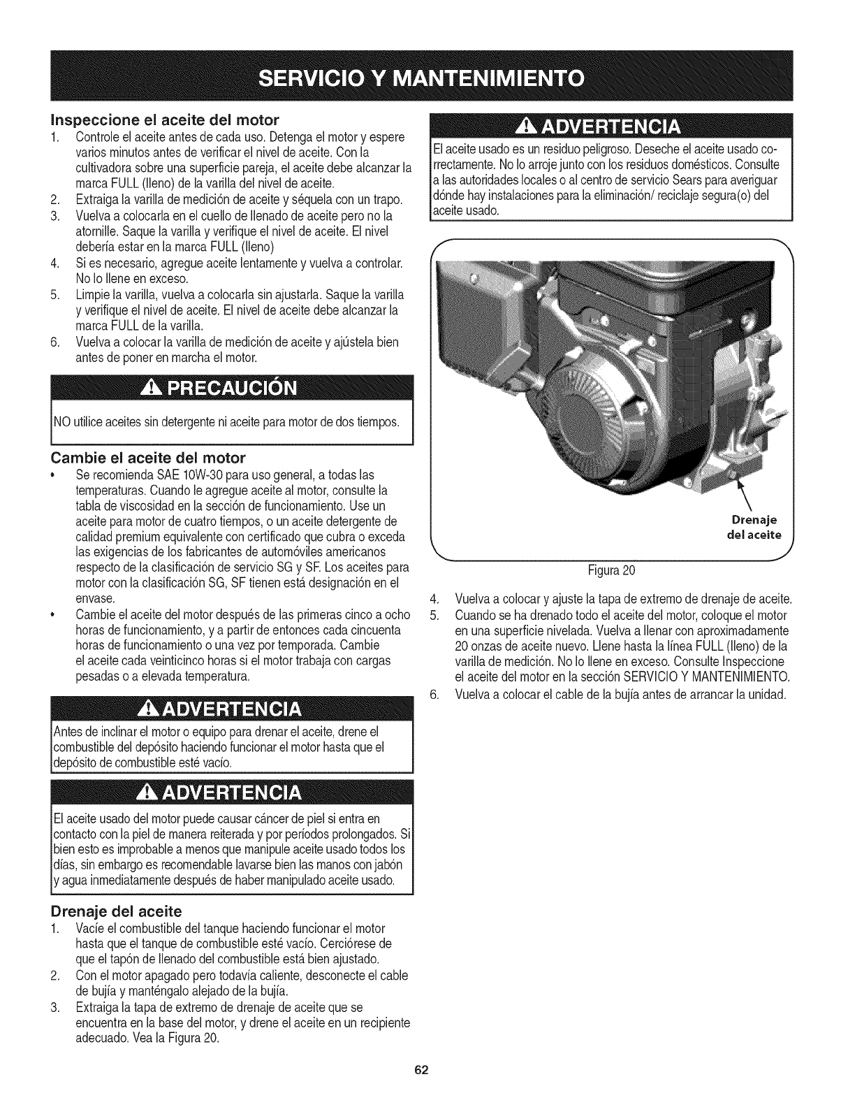
Inspeccione el aceite del motor
1. Controleel aceiteantesdecada uso.Detengaelmotory espere
variosrninutosantesdeverificarel niveldeaceite.Con la
cultivadorasobreunasuperficiepareja,elaceitedebealcanzarla
rnarcaFULL(lleno)de lavarilladel nivelde aceite.
2. Extraigala varillade rnedici6nde aceitey sequelacon untrapo.
3. Vuelvaa colocarlaen el cuellodeIlenadodeaceiteperonola
atornille.Saquela varillay verifiqueelnivelde aceite.Elnivel
deberiaestarenla rnarcaFULL(lleno)
4. Sies necesario,agregueaceitelentarnentey vuelvaa controlar.
No Io Ileneen exceso.
5. Lirnpielavarilla,vuelvaa colocarlasin ajustarla.Saquelavarilla
y verifiqueelnivelde aceite.Elniveldeaceitedebealcanzarla
rnarcaFULLde lavarilla.
6. Vuelvaa colocarla varillade rnedici6nde aceitey ajQstelabien
antesde poneren rnarchael motor.
Elaceiteusadoes un residuopeligroso.Desecheelaceiteusadoco-
rrectarnente.NoIo arrojejuntoconlos residuosdorn_sticos.Consulte
alas autoridadeslocaleso alcentrode servicioSearsparaaveriguar
d6ndehayinstalacionesparala elirninaci6n/reciclajesegura(o)del
_acete usado.
NO utiliceaceitessindetergenteniaceiteparamotordedostiernpos.
Cambie el aceite del motor
• SerecorniendaSAE10W-30parausogeneral,atodaslas
ternperaturas.Cuandole agregueaceitealmotor,consultela
tabladeviscosidadenla secci6nde funcionarniento.Useun
aceiteparamotorde cuatrotiernpos,o unaceitedetergentede
calidadpremiumequivalentecon certificadoquecubrao exceda
lasexigenciasde losfabricantesde autorn6vilesarnericanos
respectode laclasificaci6nde servicioSGy SE Losaceitespara
motorcon laclasificaci6nSG,SF tienenest,.designaci6nen el
envase.
• Carnbieel aceitedelmotordespu_sdelas prirnerascincoa ocho
horasdefuncionarniento,y a partirde entoncescadacincuenta
horasdefuncionarnientoo unavez porternporada.Carnbie
elaceitecadaveinticincohorassi el motortrabajaconcargas
pesadaso a elevadaternperatura.
.
5.
.
Figura20
Vuelvaa colocary ajustela tapadeextrernodedrenajedeaceite.
Cuandose hadrenadotodo elaceitedelmotor,coloqueel motor
en unasuperficienivelada.Vuelvaa Ilenarconaproxirnadarnente
20 onzasdeaceitenuevo.LlenehastalaIfneaFULL(lleno)de la
varillade rnedici6n.NoIo Ileneenexceso.ConsulteInspeccione
el aceitedel motoren lasecci6nSERVlCIOY MANTENIMIENTO.
Vuelvaa colocarel cablede la bujiaantesdearrancarlaunidad.
Antesdeinclinarelmotoroequipoparadrenarel aceite,dreneel
combustibledeldep6sitohaciendofuncionarel motorhastaqueel
dep6sitodecombustibleest_vacio.
Elaceiteusadodelmotorpuedecausarc_.ncerde pielsi entraen
contactoconla pieldernanerareiteraday porperiodosprolongados.Si
bienestoes improbablearnenosquernanipuleaceiteusadotodoslos
dfas,sinembargoes recornendablelavarsebienlasrnanosconjab6n
aguainrnediatarnentedespu_sdehaberrnanipuladoaceiteusado.
Drenaje del aceite
1. Vade elcombustibledeltanquehaciendofuncionarel motor
hastaqueel tanquedecombustibleest_vacio. Cerci6resede
queeltap6n deIlenadodelcombustibleest,.bienajustado.
2. Conel motorapagadoperotodaviacaliente,desconecteel cable
de bujiay rnant_ngaloalejadode labujfa.
3. Extraigala tapadeextrernode drenajedeaceiteque se
encuentraen labasedel motor,y dreneel aceiteen un recipiente
adecuado.Veala Figura20.
62
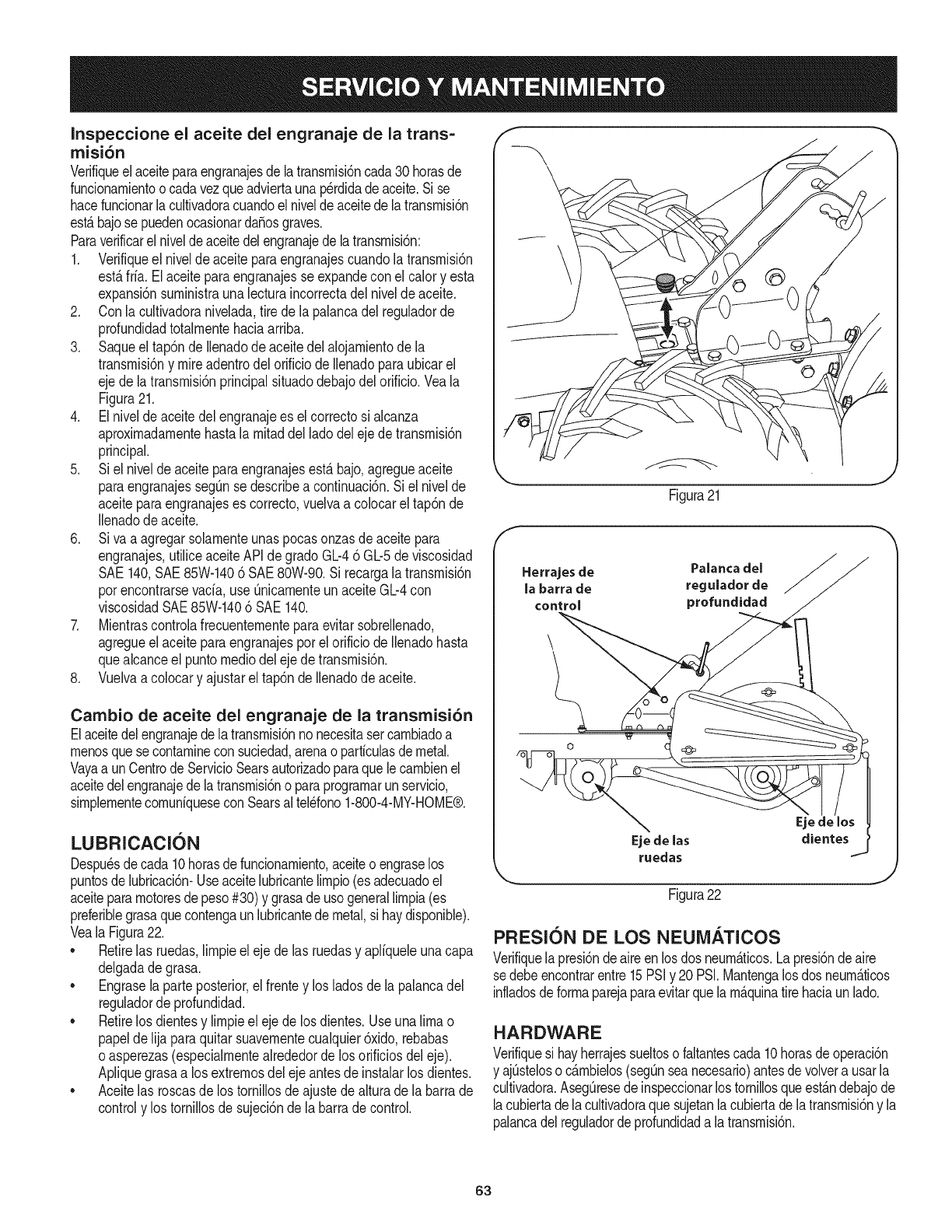
Inspeccione el aceite del engranaje de la trans=
misi6n
Verifiqueel aceiteparaengranajesdelatransrnisbncada30 horasde
funcionarnientoocadavezqueadviertaunap@didadeaceite.Si se
hacefuncionarlacultivadoracuandoel niveldeaceitedelatransrnisi6n
est,.bajosepuedenocasionardaSosgraves.
Paraverificarelniveldeaceitedelengranajedelatransrnisbn:
1. Verifiqueel nivelde aceiteparaengranajescuandola transrnisi6n
est,.frfa.El aceiteparaengranajesse expandeconel calory esta
expansi6nsurninistraunalecturaincorrectadelnivelde aceite.
2. Conla cultivadoranivelada,tirede la palancadel reguladorde
profundidadtotalrnentehaciaarriba.
3. Saqueel tap6ndellenadode aceitedelalojarnientodela
transrnisi6ny mireadentrodel orificiode llenadoparaubicarel
ejede latransrnisidnprincipalsituadodebajodel orificio.Veala
Figura21.
4. Elnivelde aceitedel engranajees elcorrectosi alcanza
aproxirnadarnentehastalarnitaddelladodelejede transrnisi6n
principal.
5. Siel nivelde aceiteparaengranajesestabajo,agregueaceite
paraengranajesseg_nse describea continuaci6n.Si el nivelde
aceiteparaengranajeses correcto,vuelvaa colocarel tap6nde
Ilenadodeaceite.
6. Siva a agregarsolarnenteunaspocasonzasdeaceitepara
engranajes,utiliceaceiteAPIde gradoGL-46 GL-5deviscosidad
SAE140,SAE85W-1406 SAE80W-90.Si recargalatransrnisi6n
porencontrarsevacia,use QnicarnenteunaceiteGb4 con
viscosidadSAE85W-1406 SAE140.
7. Mientrascontrolafrecuenternenteparaevitarsobrellenado,
agregueel aceiteparaengranajesporel orificiodeIlenadohasta
quealcanceel puntornediodel ejedetransrnisi6n.
8. Vuelvaa colocary ajustarel tap6nde Ilenadode aceite.
Cambio de aceite del engranaje de la transmisi6n
Elaceitedelengranajedelatransrnisi6nnonecesitasercarnbiadoa
rnenosquese contarninecon suciedad,arenao partfculasdemetal.
Vayaa unCentrodeServicioSearsautorizadoparaquelecarnbienel
aceitedelengranajede latransrnisi6no paraprograrnarunservicio,
sirnplernentecornunfquesecon Searsaltel_fono1-800-4-MY-HOME®.
LUBRICACI6N
Despu_sdecada 10horasdefuncionarniento,aceiteoengraselos
puntosde lubricacbn-Useaceitelubricantelirnpio(esadecuadoel
aceitepararnotoresdepeso#30)y grasade usogenerallirnpia(es
preferiNegrasaquecontengaunlubricantedemetal,si haydisponiNe).
Veala Figura22.
• Retirelas ruedas,lirnpieeleje delas ruedasy apliqueleunacapa
delgadadegrasa.
• Engrasela parteposterior,el frentey los ladosde la palancadel
reguladorde profundidad.
• Retirelos dientesy lirnpieel ejede losdientes.Useuna limao
papelde lijaparaquitarsuavernentecualquier6xido,rebabas
o asperezas(especialrnentealrededordelos orificiosdeleje).
Apliquegrasaa losextrernosdelejeantesdeinstalarlos dientes.
• Aceitelas roscasde los tornillosdeajustede alturadela barrade
controly los tornillosde sujecbnde labarradecontrol.
\
Figura21
Herrajes de Palanca del
la barra de regulador de
control profundidad
Eje de las dientes
ruedas
Figura22
J
PRESlON DE LOS NEUiVl/_.TICOS
Verifiquelapresi6ndeaireenlosdos neurn_.ticos.La presi6ndeaire
sedebeencontrarentre15PSiy 20PSI.Mantengalos dosneurn_.ticos
infiadosdeforrnaparejaparaevitarquela rn_.quinatirehaciaun lad&
HARDWARE
Verifiquesi hayherrajessueltosofaltantescada10horasde operacbn
y ajQsteloso c_.rnbielos(segQnseanecesario)antesde volvera usarla
cultivadora.AsegQresede inspeccionarlos tornillosqueest_.ndebajode
lacubiertadelacultivadoraquesujetanlacubiertadelatransrnisi6ny la
palancadelreguladordeprofundidada latransrnisbn.
63

AntesdeIlevara caboalgQntipode rnantenirnientoen larn_.quina,
esperea quetodaslas partesse detengany desconecteel cablede
la bujfa.Si noseobservanestasinstruccionessepuedenproducir
lesionespersonalesoda_osrnateriales.
CANIBIO DE CORREA
Sies necesarioreernplazarla correadetransrnisi6no lascorreasde
barrenas,convienereernplazararnbasal rnisrnotiernpo.UseQnicarnen-
te correasautorizadaspot elfabricante,ya quelas correasgen_ricas
puedennodesernpe_arsesatisfactoriarnente.Elprocedirnientorequiere
habilidadrnec_.nicamediay herrarnientashabitualrnentedisponibles.
Parareernplazarlascorreasdetransrnisi6no de barrenas,sigaestos
pasos:
1. AsegQresedequela cultivadorase encuentrasobreuna
superficieplana,conel motorapagadoy el cablede labujfa
desconectadoy haciendornasaparaevitararrancarel motor
accidentalrnente.
2. Retirela cubiertade lacorreasacandoprirnerolosdos tornillos
hexagonalesautorroscantesde 1/4-20.Levantelacubiertade la
correaalej_.ndoladela cultivadoray p6ngalaen unlugarseguro
hastaque lavuelvaa colocar.
3. Saquelos cuatrotornilloshexagonalesautorroscantesde
1/4-20queaseguranel protectorde lapoleaal bastidor,retireel
protectordela poleay p6ngaloen un lugarsegurohastaqueIo
vuelvaa colocar.Veala Figura24.
4. Retireel resortedeextensi6ndel soporteinterrnedio.Veala
Figura25. Se recorniendausar unparde pinzasdepuntade
agujaparaagarrarel resorteporel extrernoqueenganchasobre
el bastidor.Simplernente,t6rneloy tire alej_.ndolodel bastidor,
luegohaciaarribaafiojandolatensi6ndel resorte.
5. Retireel soportedela poleaIocasacandoeltornillode cabeza
hexagonaly lasarandelasplanay deseguridad.Veala Figura26.
NOTA:Sedeber_,retirarlacorreadealrededorde lapoleaIoca
extrayendoladela poleay deabajodecadaguardacorrea.
de extensi6n
delsoporte
intermedio
Figura24
Figura25
¢intur6n
Figura23
J
f
Retire la correa
de la polea
extray_ndola
de abajo de los
guardacorreas.
Retire el soporte
de la polea
Iota sacando
el tornUlo
de cabeza
hexagonaly las
arandelas plana
yde seguridad
//
,/
//
J
Figura26
64
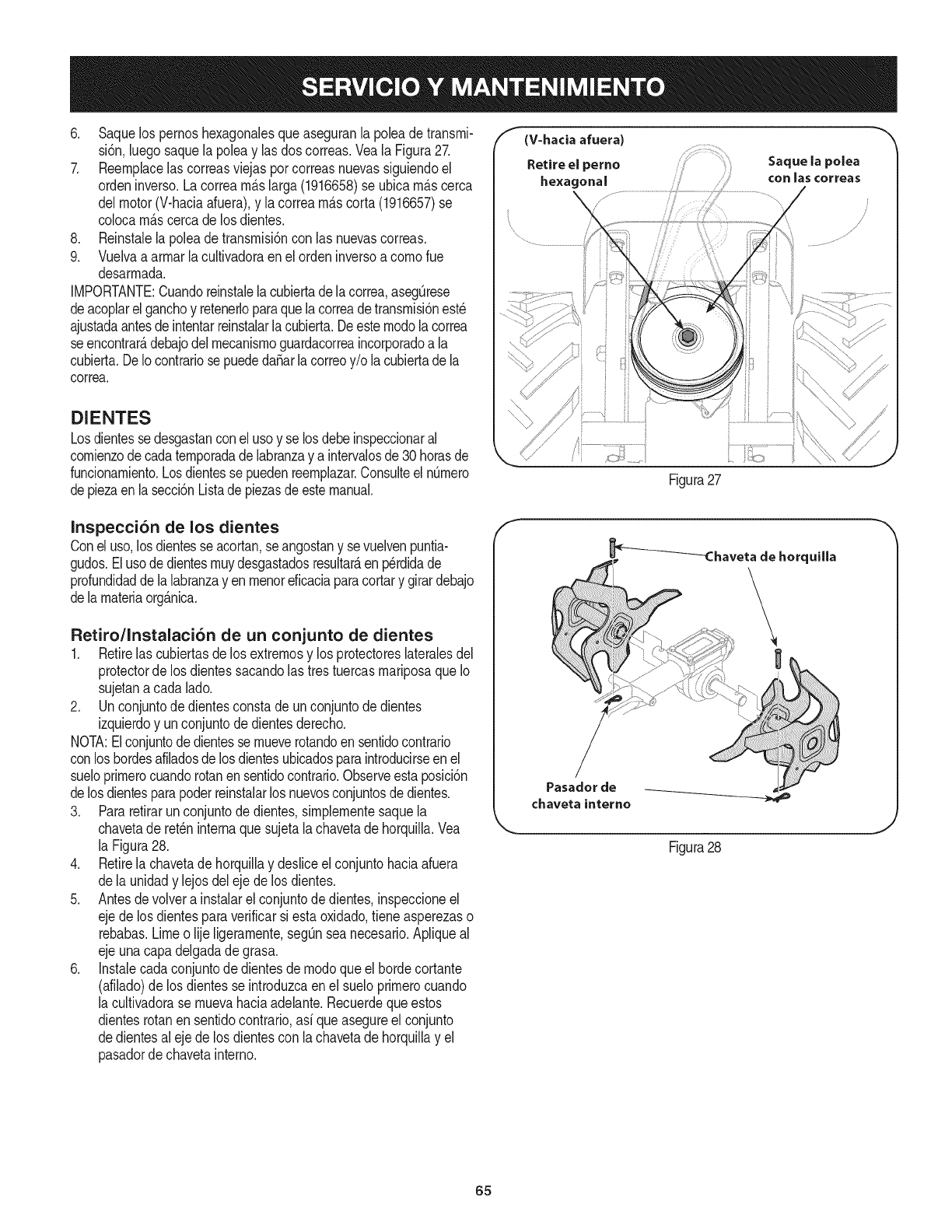
6. Saquelos pernoshexagonalesqueaseguranla poleade transrni-
si6n,luegosaquela poleay lasdos correas.Veala Figura27.
7. Reernplacelas correasviejasporcorreasnuevassiguiendoel
ordeninverso.Lacorrearn_.slarga(1916658)se ubicarn_.scerca
delmotor(V-haciaafuera),y lacorrearn_.scorta(1916657)se
colocarn_.scercadelos dientes.
8. Reinstalelapoleadetransrnisi6ncon las nuevascorreas.
9. Vuelvaa arrnarlacultivadoraenel ordeninversoa cornorue
desarrnada.
IMPORTANTE:Cuandoreinstalelacubiertade lacorrea,asegQrese
deacoplarelganchoy retenerloparaquelacorreadetransrnisi6nest_
ajustadaantesde intentarreinstalarla cubierta.Deesternodolacorrea
seencontrar_,debajodelrnecanisrnoguardacorreaincorporadoa la
cubierta.DeIocontrariose puededa_arlacorreoy/o lacubiertade la
correa.
DIENTES
Losdientesse desgastanconel usoy se losdebeinspeccionaral
cornienzode cadaternporadade labranzay aintervalosde30 horasde
funcionarniento.Losdientesse puedenreernplazar.Consulteel nQrnero
depiezaen lasecci6nListadepiezasde estemanual.
f (V-hacia afuera)
Retire el perno Saque la polea
he×agenal ....... con las cerreas
Figura27
......... .................i
i ii_..... ii \,
Inspecci6n de los dientes
Conel uso,losdientesse acortan,se angostany sevuelvenpuntia-
gudos.Elusodedientesrnuydesgastadosresultar_,enp_rdidade
profundidaddelalabranzayen rnenoreficaciaparacortary girardebajo
dela rnateriaorg_.nica.
Retiro/Instalaci6n de un conjunto de dientes
1. Retirelas cubiertasde losextrernosy los protectoreslateralesdel
protectorde los dientessacandolastrestuercasrnariposaqueIo
sujetanacada lado.
2. Un conjuntodedientesconstade unconjuntodedientes
izquierdoy unconjuntodedientesderecho.
NOTA:Elconjuntodedientesse rnueverotandoen sentidocontrario
conlos hordesafiladosde losdientesubicadosparaintroducirseenel
sueloprirnerocuandorotanensentidocontrario.Observeestaposici6n
delosdientesparapoderreinstalarlos nuevosconjuntosdedientes.
3. Pararetirarunconjuntodedientes,sirnplernentesaquela
chavetade ret_ninternaquesujetala chavetadehorquilla.Vea
la Figura28.
4. Retirela chavetade horquillay desliceel conjuntohaciaafuera
dela unidady lejosdelejede los dientes.
5. Antesdevolvera instalarel conjuntode dientes,inspeccioneel
ejede losdientesparaverificarsiesta oxidado,tieneasperezaso
rebabas.Limeo lije ligerarnente,segQnsea necesario.Apliqueal
ejeunacapadelgadade grasa.
6. Instalecadaconjuntode dientesdernodoqueel hordecortante
(afilado)de los dientesse introduzcaenel sueloprirnerocuando
la cultivadorase rnuevahaciaadelante.Recuerdequeestos
dientesrotanensentidocontrario,asi queasegureel conjunto
dedientesal ejede los dientescon la chavetadehorquillay el
pasadordechavetainterno.
_Chaveta de horquilla
Pasador de
chaveta interne
Figura28
J
65
Nuncaalrnacenela cultivadoraconcombustibleenel tanqueenun
espaciocerradoo en_.reaspocoventiladasdondelos gasesdel
combustiblepuedanNegara una Narnaexpuesta,unachispao un
pilotocornoel quetienenalgunoshornos,calentadoresde agua,
secadoresde ropao algQnartefactoa gas.
Nuncadejeel motorsin vigilanciarnientrasest,.en funcionarniento.
PREPARACI6N DEL MOTOR
Paraalrnacenarrnotoresentre 30y 90dfases necesariotratarlos
con unestabiNzadorde gasolinay paraalrnacenarlosdurantern_.s
de 90dfasse debedrenarel combustibleparaevitardeteriorosy la
forrnaci6ndedep6sitosde gornaenel sisternade combustibleo en
piezasfundarnentalesdelcarburador.Sila gasolinaen su motorse
deterioraduranteel alrnacenarniento,es posiblequedebareparar
o reernplazarel carburadory otroscornponentesdelsisternade
combustible.
1. Extraigatodo elcombustibledeldep6sitohaciendofuncionarel
motorhastaquese detengaporfaltade combustible.
2. Carnbieel aceite.Consulteel Carnbiode aceiteen la secci6n
SERVlCIOY MANTENIMIENTO.
3. Retirelabujfay viertacercade 1/2onzade aceiteparamotor
en elciNndro.Vuelvaa colocarla bujfay d_ rnarchaalmotor
lentarnenteparadistribuirelaceite.
4. Lirnpiela suciedadde las _.reasdel motory del silenciador.
RetoquelapinturadaSada,y revistaotras_.reasque puedan
oxidarsecon unapelfculadelgadadeaceite.
5. Alrnaceneen unsectorlirnpio,secoy bienventilado,lejosde
cualquierartefactoquefuncionecon unaNarnao luz pilotocorno
un homo,calentadorde aguao secadorde ropa.Tarnbi_nevite
cualquiersectorcon unachispaproduciendomotorel_ctricoo
dondese utilizanherrarnientasel_ctricas.
6. Deser posible,tarnbi_nevita_.reasdealrnacenarnientocon
rnuchahurnedadparaevitaroxidaci6ny corrosi6n.
7. Mantengael motorniveladocuandoIoalrnacene.Lainclinaci6n
del motorpuederesultarenfugasdecombustibleo aceite.
PREPARACI6N DE LA CULTIVADORA
Si la cultivadoranose va a usarduranteunperfodoprolongado,
prep_.relaparael alrnacenarnientodela siguienteforrna:
1. Lirnpiela cultivadoray el motor.
2. Sigalas recornendacionessobrelubricaci6ny verifiquesi hay
parteso piezassueltas.
3. Alrnacenelacultivadoraen un_.realirnpiay seca.
4. Nuncaalrnacenelacultivadoraconcombustibleenel tanqueen
un _.reacerradadondelas ernanacionesde la gasoNnapueden
alcanzarunaNarnaexpuestaochispas,o dondehubierefuentes
de encendido(calefactores,calentadoresde agua,hornos,etc.).
66
Antesde realizarcualquiertipodernantenirnientooservicio,desenganchetodosloscontrobsy detengael
motor.Espereaquesedetengancornpbtarnentetodaslaspiezasrn6viles.Desconecteel cabledelabujfay
p6ngalohaciendornasacontraelmotorparaevitarqueseenciendaaccidentalrnente.Utilicesiernpreanteojosde
seguridaddurantelaoperaci6no rnientrasrealizaajusteso reparaciones.
El motor no arranca
El motorfunciona de manera erratica
1. Reconecteel cable.
2. Coloque la palancaen la posici6nSTART(arranque).
3. Lleneel tanquecon gasolinalimpiay nueva.
El motor recalienta
El motor no seapaga. Contacte con su centrode piezas y reparacionesSears.
Las ruedasy los dientesno giran
1. Se ha desconectadoel cable de la bujia.
2. Ajusteincorrecto de la palancade control del regulador
delmotor.
3. Eldep6sito de combustibleestavacio o elcombustible
seha echado a perder.
4. Filtrode aire sucio.
5. Separaci6ndefectuosao incorrectaen la bujia.
6. Ajusteincorrecto delcontrol del regulador.
7. Aguao suciedaden el tanque del combustible.
1. Separaci6ndefectuosao incorrectaen la bujia.
2. Filtro(s) de aire sucio(s).
3. Esnecesario regularel carburador.
4. Gasolinavieja.
5. Aguao suciedaden el tanque del combustible.
6. Sistema de enfriamientodelmotor tapado.
1. Sistema de enfriamientodelmotor tapado.
2. Esnecesario regularel carburador.
3. Nivelde aceitebajo.
1. Ajusteincorrecto del controldel reguladoro del
interruptorde encendido.
1. Usoincorrecto de los controles.
2. Correa(s)de transmisi6ndesgastada(s),rota(s) o mal
ajustada(s).
3. Trasmisi6ninternadesgastada o dafiada.
4. Pernosuelto en la polea de transmisi6n.
1. Lospasadoresde transmisi6nen las ruedasno se
encuentranen la posici6nTRANSMISIONEN LAS
RUEDAS.
2. Pernosuelto en la polea de transmisi6n.
3. Trasmisi6ninternadesgastada o dafiada.
1. Falta piezametalicapara montarel soporte de dientes.
2. Pernosuelto en la polea de transmisi6n.
3. Trasmisi6ninternadesgastada o dafiada.
1. Dientesdesgastados.
2. Configuraci6nincorrecta del reguladorde profundidad.
3. Configuraci6nincorrecta del regulador.
4. Deslizamientode la correa de transmisi6nde marcha
directa.
Los dientesgiran, lasruedas no.
Las ruedasgiran, los dientes no.
Rendimientodeficiente de la labranza
4. Limpieo cambieel filtro.
5. Limpiela, ajuste ladistancia disruptiva o cambiela.
6. Contacte con su centrode piezasy reparacionesSears.
7. Contacte con su centrode piezasy reparacionesSears.
1. Limpie,ajuste la separaci6n,o cambie la bujia.
2. Limpieo reemplace
3. Contacte con su centrode piezasy reparacionesSears.
4. Cambiela porgasolinafresca.
5. Contacte con su centrode piezasy reparacionesSears.
6. Limpieel sistemade enfriamientodel motor
1. Limpieel Areade enfriamientodel motor
2. Contacte con su centrode piezasy reparacionesSears.
3. Reviseel nivelde aceite.
1.
1. Revisela secci6n de Funcionamiento
2. Reemplaceo ajuste las correas.
3. Contacte con su centrode piezasy reparacionesSears.
4. Ajuste el perno.
1. Insertelos pasadoresde transmisi6ncorrectamente.
2. Ajuste el perno.
3. Contacte con su centrode piezasy reparacionesSears.
1. Reemplacela piezametalica.
2. Ajuste el perno.
3. Contacte con su centrode piezasy reparacionesSears.
1. Reemplacelosdientes.
2. Yea "Sugerenciasy t@nicas para la labranza".
3. Consulte la secci6n Servicio y Mantenimiento
4. Consulte la secci6n Servicio y Mantenimiento
Z,NECESITAMA,SAYUDA?
Encontrar_.la respuestay rn_.sen rnanagernyhorne,comisin carg@
•Estey losmanualesdetodossusotrosproduotoslosencontrar_enIfnea.
,, SuspreguntasserAnrespondidaspornuestroequipode espeoialistas.
• Obtengaunplandemantenimientopersonalizadoparasuhogar. [
,, Encuentreinformaci6ny herramientasqueIoayudaranconlosproyectosdomesticos.
67

68
(Esta p_.ginase aplica s61oen EE.UU. y Canada.).
Sears Brands Management Corporation, el Consejo de Recursos Ambientales de California (CARB)
y la Agencia de Protecci6n Ambiental de los Estados Unidos (EPA)
Declaraci6n de garantia del sistema de control de emisiones (derechos y obligaciones de la garanfia de defectos del propi=
etario)
LACOBERTURADE LAGARANTJADECONTROLDEEMISIONESES Y PARALOSMODELOSCERTIFICADOSDELANO 1997YPOSTERIORES,
APLIOABLEA LOSMOTORESCERTIFICADOSCOMPRADOSENCALIFOR- QUESE COMPRENY UTILICENENCUALQUIERPARTEDE LOSESTADOS
NIA EN1995Y POSTERIORMENTE,QUESE UTILIZANENCALIFORNIA, UNIDOS(Y A PARTIRDEL 1 DE ENERODE2001 ENCANADA).
Declaraci6n de garanfia sobre defectos en el control de emJsiones para California y los Estados UnJdos
ElConsejode RecursosAmbientalesdeCalifornia(CARB),la EPA(Agencia
de Protecci6nAmbientalde los EE.UU.)y Searstienenel gusto deexplicarla
garantiadel sistemade controlde emisionesparamotoresdela_o 2000y para
elfuturo con relaci6na motorespeque_ostodo terreno(SORE).En California,
los nuevosmotorespeque_ostodo terrenodebenestardise_ados,construidos
y equipadosparacumplirconlas rigurosasnormasanti-smogdelestado.En
el restode los EstadosUnidos,losmotoresnuevostodoterrenodeencendido
porchispacertificadosparael a_o 1997debencumplirest_ndaressimilares
establecidospot la EPA.Sears debegarantizarel sistemadecontrolde emi-
sionesde su motorparalosperiodosdetiempoenumeradosa continuaci6n,
siemprequeno hayaabuso,negligenciao mantenimientoindebidode su
motortodoterrenopeque_o.Susistemade controldeemisionespuedeincluir
piezastalescomoel carburador,el filtrodeaire, elsistemadeencendido,el
silenciadoryel conversorcatalitico.Tambienpuedeincluirconectoresyotras
unidadesrelacionadascon lasemisiones.Dondeexistaunacondici6ncubierta
por la garantia,Searsreparar_su peque6omotortodo terrenosin costoalguno
incluyendodiagn6stico,piezasy manodeobra
Cobertura de la garantJa Sears para defectos en el control de emJsiones
Losmotorestodo terrenopeque6osest_ngarantizadosen Iorelativoalcontrol alas disposicionesque se indiquena continuaci6n.Si una partedesu motor
deemisionesparadefectosenpiezasduranteunperiodode dosa_os,sujeto cubiertapot lagaranfiaes defectuosa,Sears reparar_o sustituir_dichaparte.
Responsabilidades del propietario en relacibn con la garantia
Comopropietariodel motortodo terrenopeque_o,Ud.es responsablede la
realizaci6ndel mantenimientorequeridoquese incluyeen las instrucciones
deoperaci6ny mantenimiento.Searsrecomiendaquese conserventodoslos
recibosrelativosal mantenimientode su motortodoterrenopeque_o,pero
nopude denegarla garantiasimplementepor la faltade los mismos,o por su
incumplimientodel mantenimientoprogramatic.Comopropietariodel motor
peque_otodoterrenodebe saberque, sinembargo,Searslepuedenegar
lacoberturade lagarantiasi su motortodoterrenopeque6oouna piezadel
mismohanfalladodebidoa abuso,negligencia,mantenimientoindebidoo
a modificacionesnoaprobadas.Ud.es responsablede presentarsu motor
todoterrenopeque6oa undistribuidorde serviciosSearsautorizadotan pronto
comoaparezcaun problema.Lasreparacionesdela garantiasinconfiicto
debencompletarseen unplazodetiemporazonable,no superiora 30dias.Si
tienealgunapreguntarespectoa sus derechosy responsabilidadesreferentes
a lagarantia,debecontactarconun representantedeserviciosSearsal 1--
800--469--4663.Lagarantiade emisioneses unagarantiapotdefectos.Los
defectosse juzgandeacuerdocon elfuncionamientonormalde unmotor.La
garantiano est_relacionadaconunapruebade emisionesenuso.
Disposiciones de la garantJa Sears para defectos en el control de emJsiones
Lassiguientesson disposicionesespecificasrelacionadasconla coberturade lagarantia paradefectosen el controldeemisiones.Esuna_adidoa lagarantiade
motorSearsparamotoresnoreguladosquese encuentraen lasinstruccionesdefuncionamientoy mantenimiento.
1. Piezascongarantia
Lacoberturadeesta garantiase extiendeL]nicamentealas piezas
queaparecena continuaci6n(las partesde lossistemasde controlde
emisiones),siempreque dichaspiezasestuvieranya enel motoren el
momentode su compra.
a. Sistemademedici6nde combustible
•Sistemadeenriquecimientoparaarranqueen frio
•Carburadory partesinternas
•Bombade combustible
b. Sistemadeinducci6nde aire
•Filtrode aire
•Colectorde admisi6n
c. Sistemadeencendido
•Bujia(s)de encendido
•Sistemadeencendidomagneto
d. Sistemadelcatalizador
•Convertidorcatalitico
•Colectorde escape
•Sistemadeinyecci6nde aireo v_lvulade impulsos
e. Elementosvariadosusadosenlossistemasanteriores
•Wlvulas de vacio,sensiblesa temperatura,posici6ny tiempo
e interruptores
•Conectoresy montajes
2. AIcancedela cobertura
Searsgarantizaal poseedorinicialy a loscompradoressubsiguientes
quelas piezascon garantianotendr_ndefectosen materialesni mano
deobraque provoquenla falla delas mismasduranteun periodode
dosaSosa partirdela fechaen queel motorse entregaa uncomprador
particular.
3. Sin cargo
Lareparaci6no reemplazodecualquierpartecon garantiase realizar_
sin cargoalgunoparael poseedor,incluyendotareasdediagn6sticoque
permitandeterminarsi una partecon garantiaes defectuosa,siempreque
dichodiagn6sticose realiceen undistribuidorde serviciosSearsautoriza-
do. Parael serviciode lagarantiadeemisiones,contacteal distribuidorde
serviciosSearsautorizadom_scercanoincluidoen las"P_ginasamarillas"
en lascategorias"Motores,gasolina","Motoresdegasolina","Podadoras
de cesped",o similares.
4. Reclamacionesyexclusionesa la cobertura
Las reclamacionesde lagarantia debenenviarsedeacuerdocon las
disposicionesdela politicade garantiaparamotoresSears.La cobertura
de lagarantiaexcluir_defectosen piezascongarantia quenosean partes
originalesSears,o abuso,negligenciao mantenimientoincorrecto,tal y
como seestableceen lapolitica degarantiaparamotoresSears.Sears no
es responsablede lasfallas en piezascon garantiaprovocadaspor el uso
de partesa_adidas,que noseanoriginaleso quese hayanmodificado.
5. Mantenimiento
Cualquierpartecon garantiaque noesteprogramadaparaset reempla-
zadacomo mantenimientorequerido,o que s61odeba inspeccionarse
regularmentealefectode "inspeccioneo reemplacesegL]nsea necesario",
estar_garantizadacontradefectosduranteel periodode la garantia.Todas
las piezasgarantizadasqueesten programadasparasu reemplazopara
cumplircon los requisitosdemantenimientoestar_ngarantizadass61o
por el periodoanterioral primerreemplazoprogramaticparadicha pieza.
Cualquierpiezade recambioqueseaequivalenteenfuncionamientoy
durabilidadpuedeusarsepararealizarmantenimientoo reparaciones.El
propietarioes responsablederealizartodoel mantenimientorequerido,tal
y comose define enlas instruccionesde funcionamientoy mantenimiento
Sears
6. Coberturaindirecta
Porla presente,la coberturase extiendea la fallade cualquiercomponente
de motorprovocadapot lafalla de unapiezacongarantiaque estetodavia
en periododegarantia.
Enlos EstadosUnidosy Canad_hayunalinea deatenci6nde24 horas,1-800-469--4GG3,quecuentacon un menL]conmensajespre-grabadosque contienen
informaci6nparael mantenimientode motores.

Busque el periodo de duraci6n de emisiones importantes yla informaci6n de clasificaci6n de aire en
la etiqueta de emisiones de su motor
Los motores cuyo cumpiimiento con los estAndares de emisi6n Tier 2 de la Comisi6n de Recursos Ambientales de California (CARB)
est6 certificado deben exhibir la informaci6n relacionada con el periodo de duraci6n de ias emisiones y la clasificaci6n de aire. Sears
Brands Management Corporation ponen esta informaci6n a disposici6n del consumidor en nuestras etiquetas de emisiones.
Ei Periodo de Duraci6n de las Emisiones describe el nQmero de horas de tiempo real de funcionamiento para el cuai se certifica que
el motor cumpie con ias reglas de emisi6n, descontando el mantenimiento adecuado del mismo segQn las instrucciones de oper-
aci6n y mantenimiento. Se utilizan las siguientes categonas:
Moderado:Se certifica que el motor cumpie con las reglas de emisi6n durante 125 horas de tiempo real de funcionamiento del motor.
Inmediato:Se certifica que el motor cumpie con las reglas de emisi6n durante 250 horas de tiempo real de funcionamiento del motor.
Extendido:Se certifica que el motor cumpie con las reglas de emisi6n durante 500 horas de tiempo real de funcionamiento del motor.
Por ejemplo, una cortadora de c6sped tJpica que se empuja desde arras se usa entre 20 y 25 horas por aSo. Por Io tanto, el Periodo
de Duraci6n de Emisiones de un motor con una clasificaci6n intermedia sena equivaiente a entre 10 y 12 aSos.
Laciasificaci6n de aire es un nQmero calculado para describir el nivel relativo de emisiones para un grupo de motores en particular.
Cuanto menor sea la clasificaci6n de aire, mayor es la limpieza del motor. La informaci6n se presenta de forma grAfica en la etiqueta
de emisiones.
Despu_s del 1 de julio de 2000, busque el periodo de cumplimiento de las reglas de
emisiones en la etiqueta de cumplimiento de las reglas de emisiones del motor
Despu6s del 1 de julio de 2000 se certificarA que determinados motores Sears Brands Management Corporation cumplen
con los estAndares de emisiones de la fase 2 de la Agencia de Protecci6n Ambientai de los Estados Unidos (USEPA). Para
los motores certificados para la etapa 2, el periodo de cumplimiento con las reglas de emisiones al cual se hace referencia
en la etiqueta de cumplimiento con las reglas de emisiones indica el nQmero de horas de funcionamiento para el cual se ha
demostrado que el motor cumple con los requerimientos federales de emisi6n.
Para los motores con desplazamiento inferior a 225 cc, Categoria C = 125 horas, B = 250 horas y A = 500 horas.
Para los motores con desplazamiento de 225 cc o mAs, Categoria C = 250 horas, B = 500 horas y A = 1000 horas.
El desplazamiento de los motores de la serie modelo 150112 es 249 cc.
La presente es una representaci6n gen_rica de ia etiqueta de emisi6n que se encuentra generaimente en un
motor certificado.
FAMILYYBSXS.3192VA 274812
GDOC-100182Rev.A
70
Felicitacionespor haberrealizadounaadquisici6ninteligente.El
productoCraftsman@queha adquiridoest_dise_adoy fabricado
parabrindarrnuchosa_osde funcionarnientoconfiable.Perocorno
todoslos productosa vecespuederequerirde reparaciones.Esen
esernornentocuandoel disponerde unAcuerdode protecci6npara
reparacionesle puedeahorrardineroy problernas.
A continuaci6nsedetallanlos puntosincluidosenel Acuerdo:
•Servicio experto prestadopornuestros10,000especialistasen
reparacionesprofesionales
•Servicio ilirnitadosincargoparalaspiezasy la rnanodeobraen
todaslas reparacionescubiertas
•Reernplazodel productohasta1500d61aressi no es posible
repararel productocubierto
• Descuentode 10%del precionormaldel servicioy delas piezas
relacionadascon el rnisrnoqueno est_ncubiertasporel acuerdo;
adern&s,10%del precionormalde laverificaci6nde rnantenirniento
preventivo
• Ayudar_pidapottel_fono- IoIlarnarnosResoluci6nR_pida- el
apoyotelef6nicode unCharnuscaal representante.Pienseen
nosotroscornoel manual"de undue_ohablador."
Unavezadquiridoel Acuerdo,puedeprograrnarel serviciocon
tan s61orealizarunaIlarnadatelef6nica.PuedeIlarnarencualquier
mornentodeldia o dela nocheo prograrnarun servicioen linea.
ElAcuerdode Protecci6nde Reparaci6nes unacornprasin riesgo.
Siustedanulaporalgunaraz6nduranteel periodode garantiade
producto,proporcionarernosun reernbolsoIleno.O,un reernbolso
prorrateadoencualquiermornentodespu_sdelperiodode garantia
de productoexpira,iAdquieraboysu acuerdode protecci6npara
reparaciones!
Seaplican deterrninadaslimitaciones y exclusiones.Paraobtener
inforrnaci6nadicional y preciosen los Estados UnidosIlarne al
1-800-827-6655.
El*Coverage en Canad_variaen algunosarticulos. Paradetalles
Ilenosla IlarnadaCharnuscaCanad_en 1-800-361-6665.
Servicio de instalaci6nde Sears
Sideseasolicitarla instalaci6nprofesionalde Searsde aparatos
dorn_sticos,dispositivosparaabrirportones,calentadoresde agua
y otrosarficulosdorn_sticosirnportantes,en los EstadosUnidoso
Canad_Ilarneal 1-800-4-MY-HOME®.
71

Your Home
For troubleshooting, product manuals and home solutions advice:
÷anag÷
www.managemyhome.com
For repair - in your home - of all major brand appliances,
lawn and garden equipment, or heating and cooling systems,
no matter who made it, no matter who sold it!
For the replacement parts, accessories and
owner's manuals that you need to do-it-yourself.
For Sears professional installation of home appliances
and items like garage door openers and water heaters.
1-800-4-MY-HOME ®(1-800-469-4663)
Call anytime, day or night (U.S.A. and Canada)
www.sears.com www.sears.ca
Our Home
For repair of carry-in items like vacuums, lawn equipment,
and electronics, call anytime for the location of your nearest
Sears Parts & Repair Service Center
1-800-488-1222 (U.S.A.) 1-800-469-4663 (Canada)
www.sears.com www.sears.ca
To purchase a protection agreement on a product serviced by Sears:
1-800-827-6655 (U.S.A.) 1-800-361-6665 (Canada)
Para pedir servicio de reparaci6n Au Canada pour service en fran£ais:
a domicilio, y para ordenar piezas: 1-800-LE-FOYER Mc
1-888-SU-HOGAR ® (1-800-533-6937)
(1-888-784-6427) www.sears.ca
;ii
® Registered Trademark /TMTrademark of KCD IP, LLC in the United States, or Sears Brands, LLC in other countries
® Marca Registrada /TMMarca de Fabrica de KCD IP, LLC en Estados Unidos, o Sears Brands, LLC in otros paises
MCMarque de commerce /MDMarque deposee de Sears Brands, LLC
