KMW DONGLE-PL Zigbee Module User Manual
KMW INC. Zigbee Module
UserManual.wiki
>
KMW
>
DONGLE PL User Manual
User Manual
Navigation menu
Upload a User Manual
Namespaces
Wiki Guide
HTML
PDF
Info
Views
User Manual
Discussion / Help
Navigation
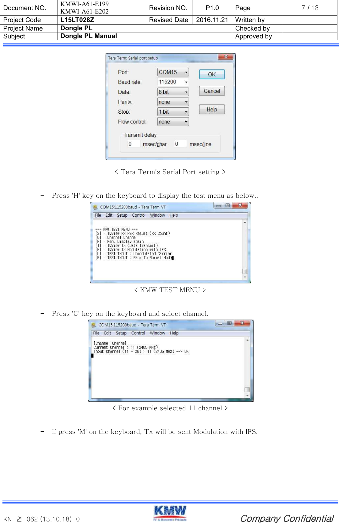
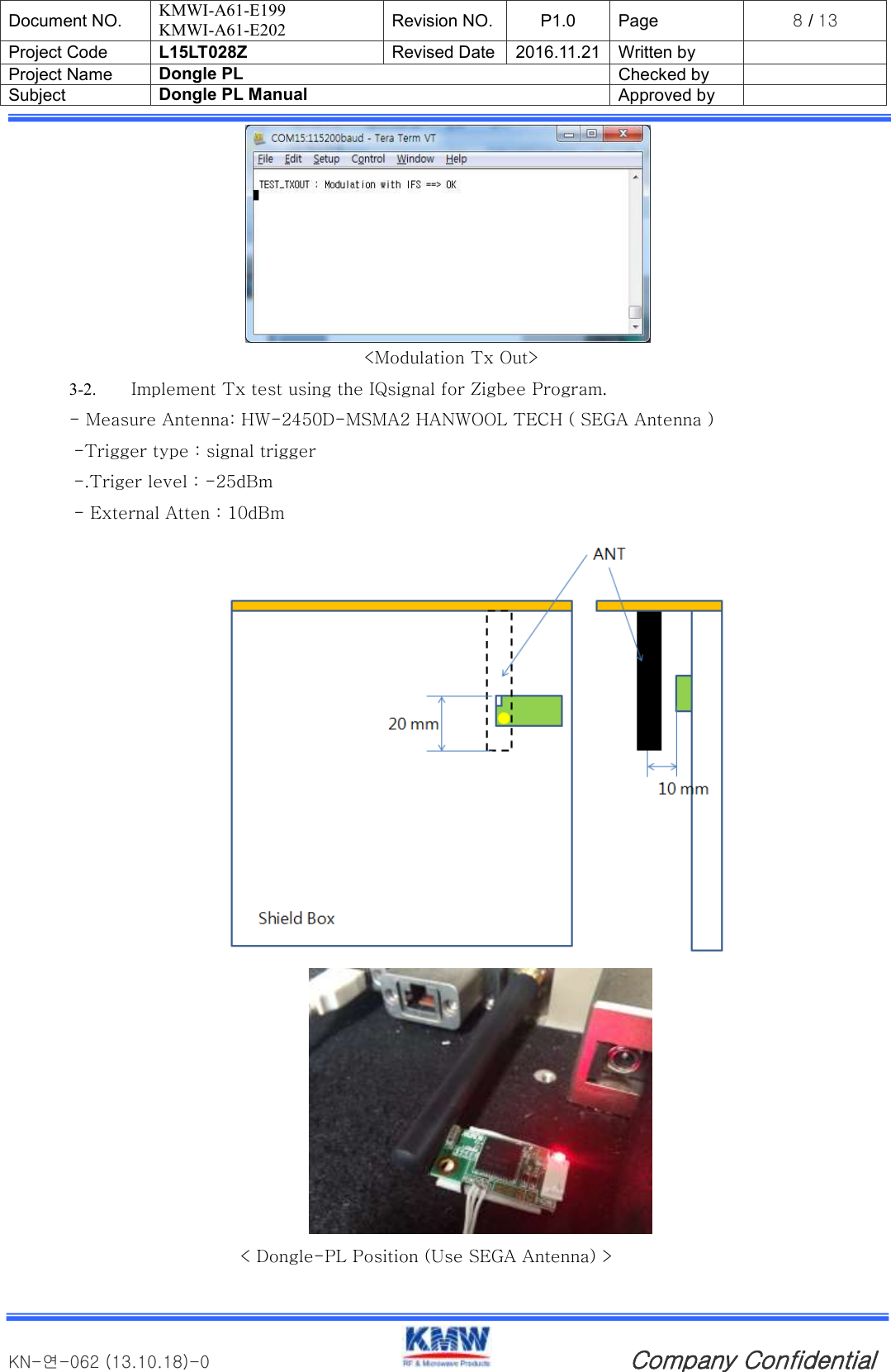
![Document NO. KMWI-A61-E199 KMWI-A61-E202 Revision NO. P1.0 Page 9 / 13 Project Code L15LT028Z Revised Date 2016.11.21 Written by Project Name Dongle PL Checked by Subject Dongle PL Manual Approved by KN-연-062 (13.10.18)-0 Company Confidential < Tx test measure > - Compare with the following items to check for defects < Zigbee Rx Test ChecK List> Req'd Spec Remark Transmit Power ≥3dBm [6.9.5]IEEE802.15.4-2006 Spectrum PSD mask 확인 [6.5.3.1]IEEE802.15.4-2006 Transmit Center Frequency Tolerance ±40ppm [6.9.4]IEEE802.15.4-2006 Error Vector Magnitude ≤35% [6.9.3]IEEE802.15.4-2006](https://usermanual.wiki/KMW/DONGLE-PL/User-Guide-3244331-Page-9.png)
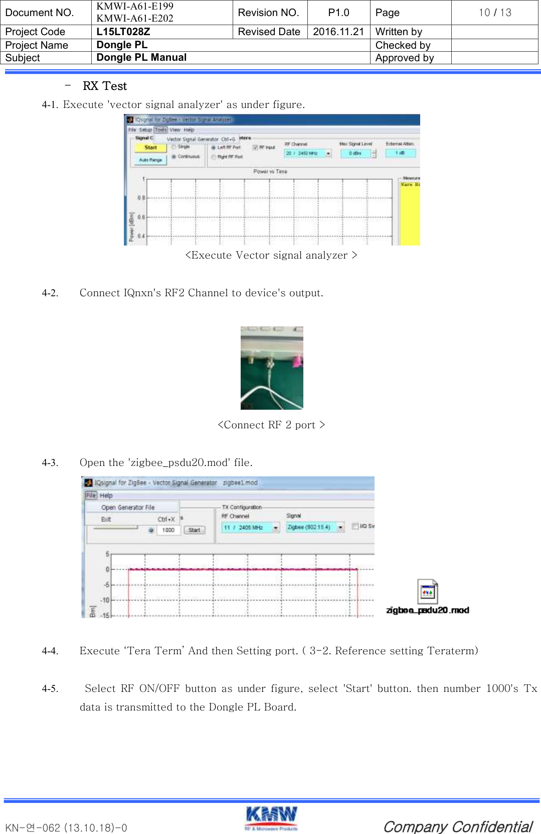
![Document NO. KMWI-A61-E199 KMWI-A61-E202 Revision NO. P1.0 Page 11 / 13 Project Code L15LT028Z Revised Date 2016.11.21 Written by Project Name Dongle PL Checked by Subject Dongle PL Manual Approved by KN-연-062 (13.10.18)-0 Company Confidential <RF ON/OFF, Start Button > 4-6. If press '2' on the keyboard, can be check transmitted result. < Tera Term Rx count Output Screen > - Compare with the following items to check for defects Req'd Spec Remark Receiver Sensitivity ≥-75dBm [6.5.3.3]IEEE802.15.4-2006 (≥-85dBm) Packet Error Rate(1000) ≤1% [6.5.3.3]IEEE802.15.4-2006 Receiver maximum input level -20dBm [6.9.6]IEEE802.15.4-2006 <IEEE802.15.4 standardize Zigbee Rx Test ChecK List> Specified as ≥-85dBm on IEEE802.15.4-2006, Changed to ≥-75dBm considering that the test environment is wireless.](https://usermanual.wiki/KMW/DONGLE-PL/User-Guide-3244331-Page-11.png)