Contents
- 1. POD User Manual_v0.9_Revised_Part1
- 2. POD User Manual_v0.9_Revised_Part2
POD User Manual_v0.9_Revised_Part2
User Manual for POD Systems Revision: 0.9
51
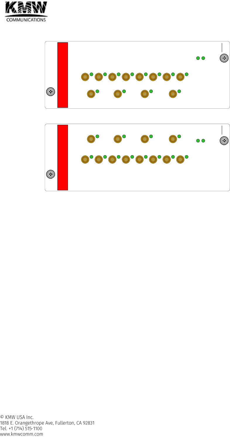
2.1.11 POD-H-STM-8x4
Figure 2-41 POD-H-STM-8x4-DL
Figure 2-42 POD-H-STM-8x4-UL
2.1.11.1 Functions and features
- Programmable sectorization can be supported by using H-STM-8x4.
- Based on programmed sector definition, DL output signals received from H-FEM are combined by each
sector and transferred to H-DTM, or H-HOM.
- Based on programmed sector definition, received UL signals from H-DTM, or H-HOM are distributed and
transferred to H-FEM.
- For each sector, controls Power Ratio for multiple H-FEM with same frequency band to share DL output
power at Remote Unit
- ALC function for DL/UL Path
- To minimize negative effects by unused input/output ports such as the degradation of VSWR or isolation
between ports, the unused ports can be switched into 50 ohm termination by user.
- When any one sector consists of remote unit less than 4, H-STM-8x4 can be connected to H-HOM-L directly
without H-DTM.
In this case, the attenuator in the common path of H-STM-8x8 should add 15dB attenuation using web
based GUI to compensate the loss of H-DTM.
2.1.11.2 Specifications
- Frequency range: 600~2700MHz
- Maximum RF Power: -10dBm@DL, 25dBm@UL
- Size, weight, and power consumption : refer to Table 2-1
STM-8x4 DL
PWR
KMW
#1
#2
#3
#4
#1
#2
#3
#4
#5
#6
#7
#8
ALM
STM-8x4 UL
PWR
KMW
#1
#2
#3
#4
#1
#2
#3
#4
#5
#6
#7
#8
ALM
User Manual for POD Systems Revision: 0.9
52
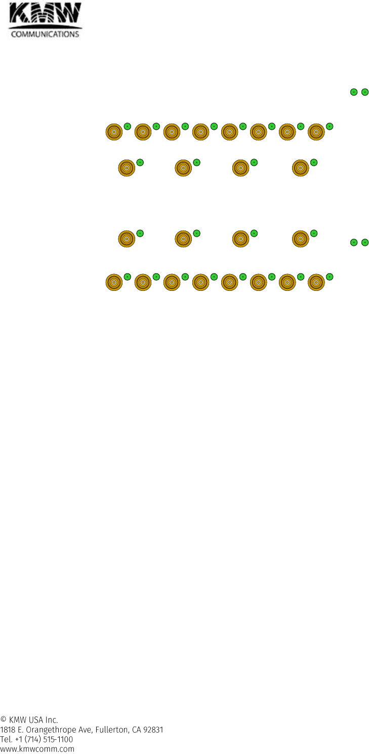
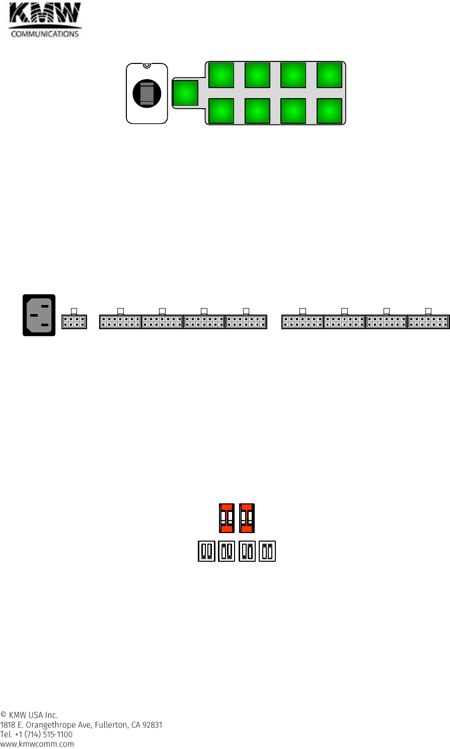
2.1.11.3 RF port and LED
Figure 2-43 POD-H-STM-8x4-DL RF port and LED
Figure 2-44 POD-H-STM-8x4-UL RF port and LED
RF port
- POD-H-STM-8x4-DL
DL IN #1 ~ #8
Receives downlink signal from up to 8 H-FEM
Connected to DL output port of H-FEM
Connector Type: SMB-L Female
DL OUT #1 ~ #4
Combines inputted downlink signals and outputs to H-DTM or H-HOM by each sector
Connected to DL input port of H-DTM, or H-HOM for each sector
Connector Type: SMB-L Female
- POD-H-STM-8x4-UL
UL IN #1 ~ #8
Receives uplink signals from H-DTM, or H-HOM for each sector
Connected to UL output port of H-DTM, or H-HOM for each sector
Connector Type: SMB-L Female
UL OUT #1 ~ #4
Distributes uplink signals inputted from UL IN #1~#8 port by each sector and outputs to H-
FEM
Connected to UL input port of H-FEM
Connector Type: SMB-L Female
PWR
#1
#2
#3
#4
#1
#2
#3
#4
#5
#6
#7
#8
ALM
PWR
#1
#2
#3
#4
#1
#2
#3
#4
#5
#6
#7
#8
ALM
User Manual for POD Systems Revision: 0.9
53
LED
Table 2-25 POD-H-STM-8x4 LED Operation
Specifications
PWR
Solid Green
When power is on.
Off
When power is off.
ALM
Off
When POD-H-STM-8x4-DL (UL) has no alarms.
Solid Yellow
When POD-H-STM-8x4-DL (UL) has minor alarm.
Solid Red
When POD-H-STM-8x4-DL (UL) has major alarm.
DL IN #1 ~ #8
Blink Green
At the cable connection guide, green led blinks to indicate which
RF ports should be connected to.
DL OUT #1 ~ #4
Blink Green
UL IN #1 ~ #8
Blink Green
UL OUT #1 ~ #4
Blink Green
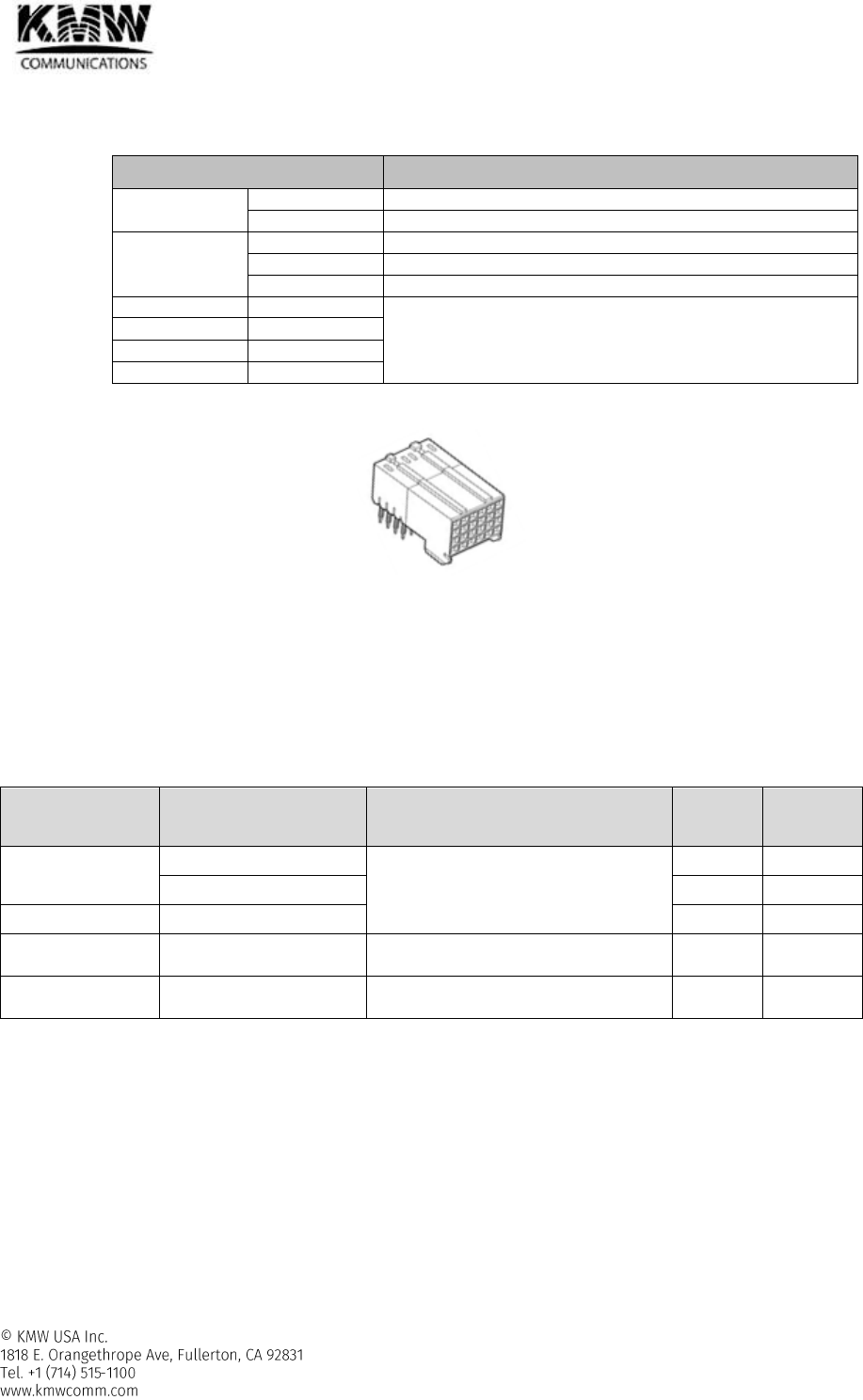
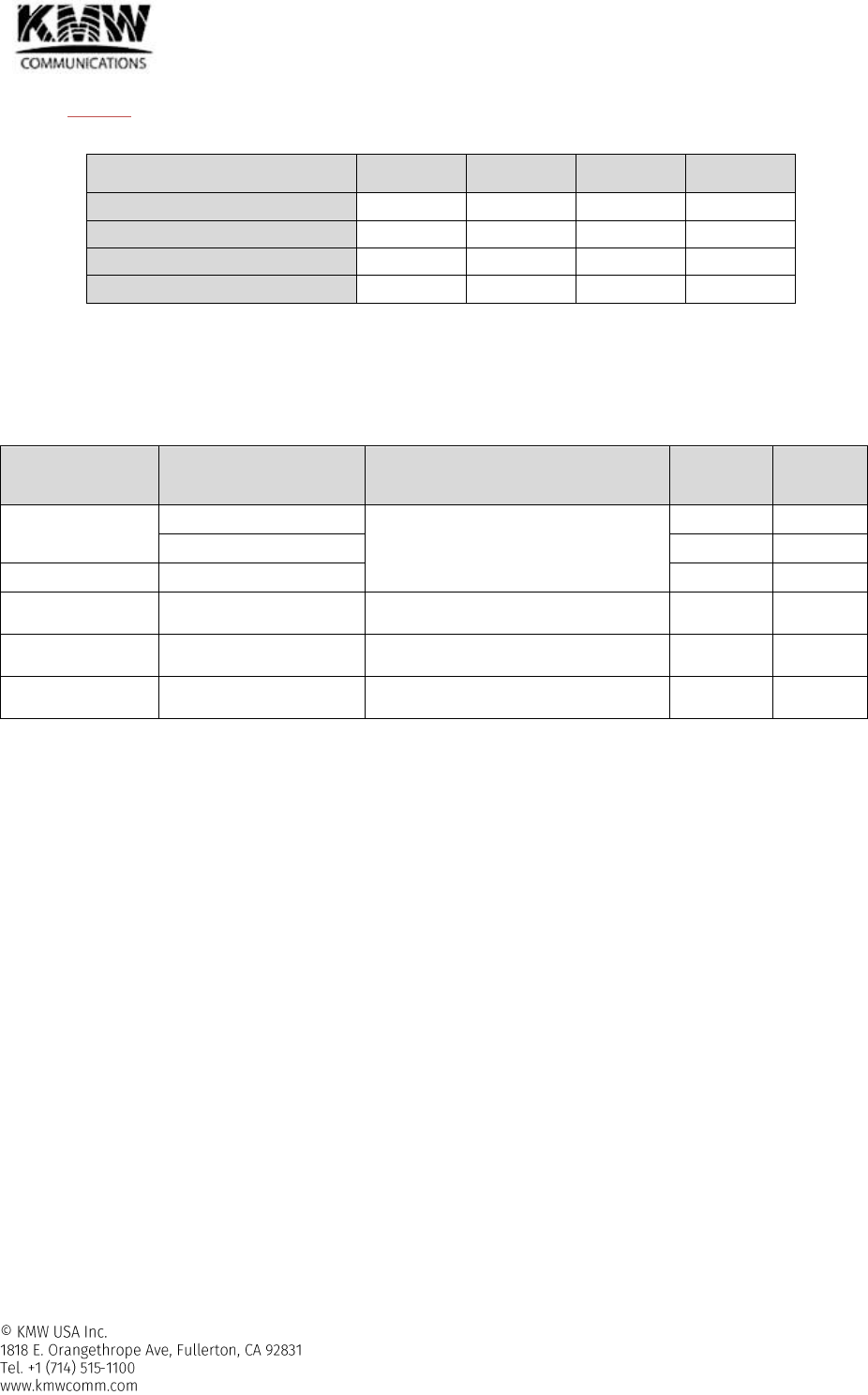
2.1.11.4 Communication port
Figure 2-45 Communication Port
- This port provides communication path between H-STM and H-SCM through backboard of H-SRU.
- +24V DC is provided through this communication port from backboard of H-SRU.
- H-STM acquires ID information such as Rack ID, Sub rack ID and Slot ID through this communication port.
The IP address of H-STM is assigned automatically using the acquired ID information.
2.1.11.5 Alarms
Table 2-26 POD-H-STM-8x8 - Alarms
Alarm Name
Description
Remedy
Alarm
Severity
LED
color
High Temperature
Temperature too high
Check environment
Major
Red
Temperature high
Minor
Yellow
Low Temperature
Temperature too low
Minor
Yellow
Link
Communication fail
Check pin of communication port/
assigned IP address
Major
Yellow
Downlink ALC
Activation
ALC activation
Check H-STM downlink input level/
attenuator configuration
Warning
Yellow
User Manual for POD Systems Revision: 0.9
54
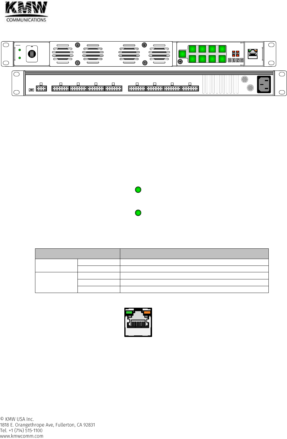
2.1.12 POD-H-PSU-x
Figure 2-46 POD-H-PSU-x
2.1.12.1 Functions and features
- Distributes +24Vdc to DMCU and up to 8 H-SRUs
- Turn on or off each DC output individually in a local or remote site
- Set Rack ID
2.1.12.2 Specifications
- AC input Range: AC 100~240V (47~63Hz)
- Size, weight, and power consumption : refer to Table 2-1
2.1.12.3 LED
Figure 2-47 POD-H-PSU-x LED
Table 2-27 POD-H-PSU-x LED Operation
Specifications
PWR
Solid Green
When power is on.
Off
When power is off.
ALM
Off
When POD-H-PSU-x has no alarms.
Solid Yellow
When POD-H-PSU-x has minor alarm.
Solid Red
When POD-H-PSU-x has major alarm.
2.1.12.4 Ethernet Port
Figure 2-48 Ethernet Port
DMCU port
- Connected to H-DMCU so that H-DMCU can monitor and control H-PSU
2.1.12.5 AC input on/off Switch & DC output on/off switch
DMCU
HPSU
Power
Alarm
#1 #2 #3 #4
#5 #6 #7 #8
DMCU
#1 #2 #3 #4
1 2 1 2
Group Rack
KMW
#1 #2 #3 #4 #5 #6 #7 #8
DMCU HSRU
Power
Alarm
DMCU
User Manual for POD Systems Revision: 0.9
55
Figure 2-49 AC input on/off Switch & DC output on/off switch
AC input on/off switch
- Be able to turn AC input on (off) manually by using AC input on/off switch
DC output on/off switch
- Be able to turn each DC output on (off) separately
- Toggle type
When you press DC output on/off switch, the LED light of DC output on/off switch and 24V DC output
turn on, and when you press it again, LED light and 24V DC output turn off.
- DC output on/off switch can be turned on (off) in local and remote site
2.1.12.6 AC input port & DC output port
Figure 2-50 AC input port & DC output port
AC input port
- Use 3 wire AC code (Line, Neutral, GND)
DC output port
- One DC output port for H-DMCU
DC output connector contains +24V DC, Rack ID, and insert pin.
- Eight DC output port for H-SRU
Each DC output connector contains +24V DC, Rack ID, and insert pin.
2.1.12.7 Rack ID
Figure 2-51 Rack ID
Group is not used
Rack ID
- Rack ID can be set from 1 to 4.
- One H-DMCU can support up to 4 racks, and one H-DMCU needs maximum 4 H-PSU because one H-PSU can
supply 24V DC power to only one rack that can be composed of up to 8 H-SRUs and one DMCU.
- H-DMCU and each H-SCM in H-SRU can identify its own rack ID through the cable connection with H-PSU.
HPSU
#1 #2 #3 #4
#5 #6 #7 #8
#1 #2 #3 #4 #5 #6 #7 #8
DMCU HSRU
#1 #2 #3 #4
1 2 1 2
Group Rack
User Manual for POD Systems Revision: 0.9
56
- CAUTION) The rack ID connected to H-DMCU must be set as 1.
Table 2-28 Rack ID
DIP Switch Setting
Group 1
Group 2
Rack 1
Rack 2
Rack ID #1
X
X
OFF
OFF
Rack ID #2
X
X
ON
OFF
Rack ID #3
X
X
OFF
ON
Rack ID #4
X
X
ON
ON
2.1.12.8 Ground port
- Refer to section 3.2.2
2.1.12.9 Alarms
Table 2-29 POD-H-PSU - Alarms
Alarm Name
Description
Remedy
Alarm
Severity
LED
color
High Temperature
Temperature too high
Check environment
Major
Red
Temperature high
Minor
Yellow
Low Temperature
Temperature too low
Minor
Yellow
Voltage
High Voltage
Check if High voltage alarm occurs again
after reset.
Major
Red
Current
High Current
Check if current alarm occurs again after
reset.
Major
Red
Low Voltage
Low Voltage
Check if low voltage alarm occurs again
after reset.
Major
Yellow
User Manual for POD Systems Revision: 0.9
57
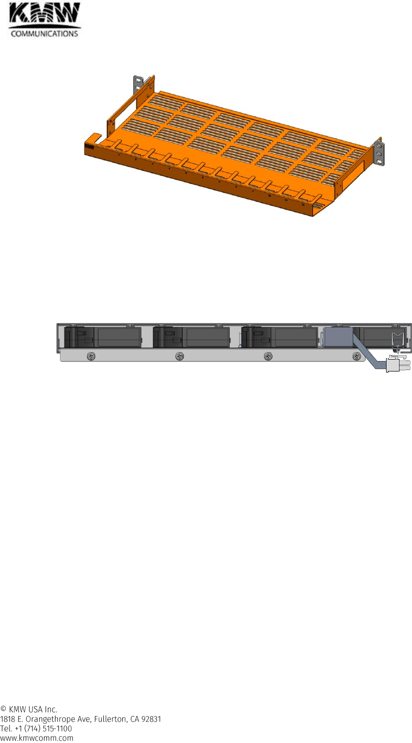
2.1.13 POD-H-CDU
Figure 2-52 POD-H-CDU
2.1.13.1 Functions and features
- Provides cable routing space when RF, optic, DC power, and Ethernet cables are connected between the
modules or units in POD DAS system.
- Has good space efficiency since H-FAU can be installed behind H-CDU
2.1.14 POD-H-FAU
Figure 2-53 POD-H-FAU
2.1.14.1 Functions and features
- Installed right above the H-SRU for dissipating heat comes from the modules installed in POD-H-SRU.
- Good space efficiency since H-FAU can be installed behind H-CDU
- DC Power is provided from FAN port located in the back side of H-SRU
- FAN speed control and FAN on/off is controlled automatically by H-SCM based on the temperature of
modules installed in H-SRU.
- FAN fail alarm is monitored by H-SCM.
2.1.14.2 The rules for installing FAN unit
- When the number of module installed in a POD-H-SRU is less than 5, it doesn’t need the installation of H-
FAU.
- When the number of module installed in a POD-H-SRU is more than 6, It needs the installation of POD-H-
FAU.
We strongly recommend that each module should be installed every other slot in a POD-H-SRU.
- When POD-H-SRUs more than 2 are stacked in one rack, one POD-H-FAU per 2 POD-H-SRU should be
installed regardless of the number of module installed in one POD-H-SRU.
We strongly recommend that each module should be installed with sufficient gap as far as possible
when the modules in a POD-H-SRU are not fully installed.
2.1.14.3 Port
- H-FAU must be connected with FAN port which is located in the back of H-SRU (refer to Figure 2-9) by
provided signal cable.

User Manual for POD Systems Revision: 0.9
58
- Control signal for FAN speed control, DC power and FAN alarm signal are transferred between H-FAU and
H-SCM through this signal cable.
2.1.14.4 Alarms
Table 2-30 POD-H-FAU - Alarms
Alarm Name
Description
Remedy
Alarm
Severity
LED
color
FAN
FAN fail
Replace FAN
Minor
Yellow
User Manual for POD Systems Revision: 0.9
59
2.2 Remote Unit
RU (Remote Unit) provides wireless service coverage to users by transmitting downlink signal through the
service antenna.
Remote units which is supported by KMW are as below.
- 7/5/3 band RU for commercial band service (POD-R-7S8CPAWB-2730-AC/DC)
- PS700/800 RU for public safety band service (POD-R-P78-27-AC/DC)
- High power RU with 20/40W output power (POD-R-4346-AC/DC)
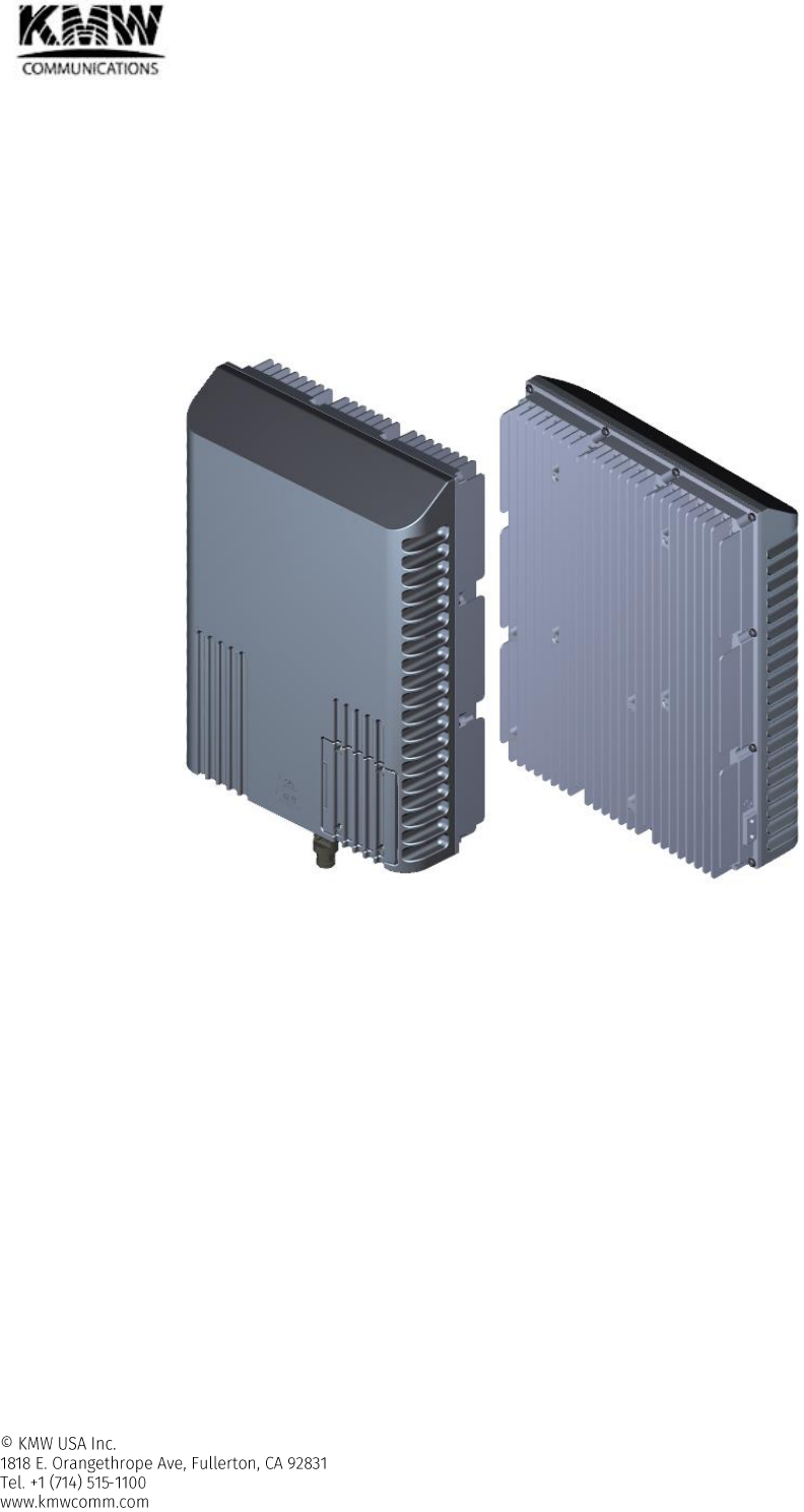
2.2.1 7/5/3 band RU for commercial band service (POD-R-7S8CPAWB-2730-AC/DC)
Figure 2-54 Remote Unit – 7/5/3 band
2.2.1.1 Functions and features
- Supported frequency band
3_band RU: SMR800, PCS, and 2.6G TDD
5_band RU: 700M, 850M, PCS, AWS, and WCS
7_band RU: 700M, SMR800+850M, PCS, AWS, WCS, and 2.6G TDD
- VSWR measurement function for checking VSWR of the connected service antenna
- Built-in Test tone generator in order to check uplink path verification
- Increase scalability by supporting expansion RU
Expansion RU is connected with main RU through AUX DL/UL port by using RF cable
Expansion RU can be added, when it needs additional frequency band other than frequency bands
being used in main RU, or additional filter attenuation in the frequency band being used in main RU. In
the latter case, the frequency band which needs additional filter attenuation must be off in main RU
and replaced by the frequency band with strengthened filter attenuation in expansion RU.
2.2.1.2 Specifications
Common Specifications
- Operating Temperature: -40~55C
User Manual for POD Systems Revision: 0.9
60
- Input Power
AC type: 110V, 50-60 Hz
DC Type: -48V
- IP rating: IP65
- Cooling method: convection cooling
- Dimension: (WxHxD) 13 x 17.3 x 4.7 in (330 x 440 x 120mm)
- Weight: 37.5 lbs (17kg)
-
700M, SMR800 + 850M
Table 2-31 3/5/7 band RU - 700M, SMR800 + 850M Specifications
700M
SMR800+850M
Lower ABC
Upper C
Frequency Band
Downlink
728.0M - 746.0M
746.0M - 756.0M
862.0M - 894.0M
Uplink
698.0M - 716.0M
777.0M - 787.0M
817.0M - 849.0M
Bandwidth
18.0 MHz
10.0 MHz
32 MHz
Mean Gain
Downlink
36 ± 1.0 dB
36 ± 1.0 dB
Uplink
37 ± 1.0 dB
37±1.0 dB
37 ± 1.0 dB
Maximum Gain
Downlink
42 dB
Uplink
37 dB
Ripple(p-p)
Downlink
2.5 dB
2.0 dB
Uplink
2.5 dB
4.0 dB @Full band
2.5dB@ 777~786M
2.0 dB
Maximum downlink output power
27 dBm
27 dBm
Uplink Noise Figure @center freq.
4.00 dB
4.00 dB
4.00 dB
VSWR
< 1:1.7
Delay
< 5.00 us
EVM
< 5.0 % @E-TM 3.1
Operating band unwanted emissions
Meet FCC, 3GPP WCDMA/LTE Repeater Spec., 3GPP2 CDMA spec.
Out of band emission
Meet FCC, 3GPP WCDMA/LTE Repeater Spec., 3GPP2 CDMA spec.
PCS, AWS
Table 2-32 3/5/7 band RU – PCS, AWS Specifications
PCS
AWS
Frequency Band
Downlink
1930.0M - 1995.0M
2110.0M - 2180.0M
Uplink
1850.0M-1915.0M
1710.0M-1780.0M
(1710~1755 M for BDA application)
Bandwidth
65.0 MHz
70.0 MHz
Mean Gain
Downlink
39 ± 1.0 dB
39 ± 1.0 dB
Uplink
40 ± 1.0 dB
40 ± 1.0 dB
Maximum Gain
Downlink
45 dB
Uplink
40 dB
Ripple(p-p)
Downlink
3.5 dB@ Full band
2.5dB (excluding band edge)
2.0 dB
Uplink
3.5 dB
2.5dB (excluding band edge)
2.0 dB
Maximum downlink output power
30 dBm
30 dBm
User Manual for POD Systems Revision: 0.9
61
PCS
AWS
Uplink Noise Figure @center freq.
4.00 dB
4.00 dB
VSWR
< 1:1.7
Delay
< 5.00 us
EVM
< 5.0 % @E-TM 3.1
Operating band unwanted emissions
Meet FCC, 3GPP WCDMA/LTE Repeater Spec., 3GPP2 CDMA spec.
Out of band emission
Meet FCC, 3GPP WCDMA/LTE Repeater Spec., 3GPP2 CDMA spec.
WCS, 2.65G
Table 2-33 3/5/7 band RU – WCS, 2.6G Specifications
WCS
2.6G
Frequency Band
Downlink
2350.0M - 2360.0M
2496.0M - 2690.0M
Uplink
2305.0M-2315.0M
2496.0M-2690.0M
Bandwidth
10.0 MHz
194.0 MHz
Mean Gain
Downlink
39 ± 1.0 dB
39 ± 1.0 dB
Uplink
40 ± 1.0 dB
40 ± 1.0 dB
Maximum Gain
Downlink
45 dB
Uplink
40 dB
Ripple(p-p)
Downlink
2.5 dB
3.5 dB
Uplink
1.75 dB
3.5 dB
Maximum downlink output power
30 dBm
30 dBm
Uplink Noise Figure @center freq.
5.00 dB
4.00 dB
VSWR
< 1:1.7
Delay
< 5.00 us
< 2.00 us
EVM
< 5.0 % @E-TM 3.1
Operating band unwanted emissions
Meet FCC, 3GPP WCDMA/LTE Repeater Spec.
Out of band emission
Meet FCC, 3GPP WCDMA/LTE Repeater Spec.
User Manual for POD Systems Revision: 0.9
62
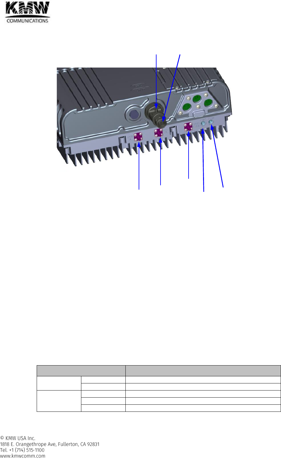
2.2.1.3 RF ports and LED
Figure 2-55 Remote Unit External Interfaces
RF port
- ANT port
Connected to Service antenna
Mini DIN, female type
- CPL port
Can be connected to spectrum analyzer to monitor downlink spectrum without interrupting wireless
service
SMA female type
- AUX UL & DL
Connected to expansion remote unit
QMA female type
- TDD sync port
Provides TDD sync signal which can be used to synchronize with TDD signal measuring equipment such
as spectrum analyzer.
QMA female type
LED
Table 2-34 7/5/3 band RU LED Operation
Specifications
PWR
Solid Green
When power is on.
Off
When power is off.
ALM
Off
When 7/5/3 band RU has no alarms.
Solid Yellow
When 7/5/3 band RU has minor alarm.
Solid Red
When 7/5/3 band RU has major alarm.
AUX UL
Port
AUX DL
Port
TDD Sync
Port ALM
LED
PWR
LED
ANT Port
CPL Port
User Manual for POD Systems Revision: 0.9
63
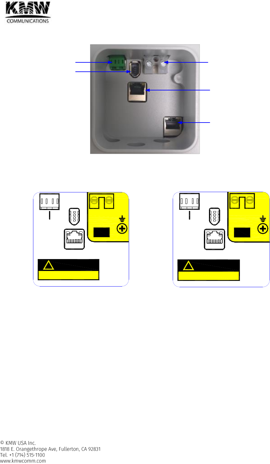
2.2.1.4 Debug Window
Figure 2-56 Debug Window
User can know the name for each port of RU by attached sticker on the cover of debug window when user opens
debug window. User can verify whether RU is AC or DC type, and RU is main RU or expansion RU.
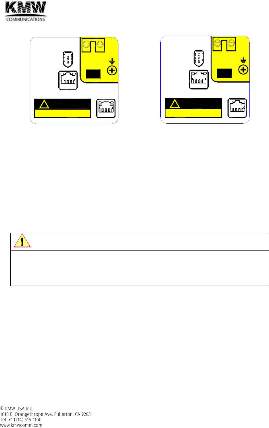
Main RU - AC type
Main RU - DC type
Optic Port AC or DC Power
input Port
Serial Port
Ethernet Port #1
Ethernet Port #2
GUI / EXT
DEBUG
UL DL
(OPTIC)
AC
(L) AC
(N)
AC
AC ONLY
CAUTION
!
DEBUG
GUI / EXT
UL DL
(OPTIC)
RTN
-48V
DC
DC ONLY
CAUTION
!
User Manual for POD Systems Revision: 0.9
64
Expansion RU - AC type
Expansion RU - DC type
Figure 2-57 Port name for each RU type
Optic port
- Connected to Head-end
- Expansion RU doesn’t need optic port because it is connected to main RU through RF cable.
- LC/APC Female type
- Wavelength: 1310nm for downlink, 1550nm for uplink
Serial port (DEBUG): Used for internal debug
AC or DC power input port
- AC or DC power source is provided into Remote unit through this port.
110V AC, 50~60Hz or DC -48V
CAUTION
Make sure whether remote unit is AC or DC type before connecting input power to AC or DC input port
Because AC and DC input port uses same connector, user might be confused, so that the wrong
connection of input power might cause severe damage of remote unit.
User can check easily whether remote unit is AC or DC type by checking the picture of sticker attached
to the debug window cover when you open it. (refer to Figure 2-57)
Ethernet Port
- Ethernet Port #1
Used as GUI Port to access web-based GUI when expansion RU is not connected
Used for connecting to expansion RU when expansion RU is connected to main RU.
Use GUI port in expansion RU to access web-based GUI when expansion RU is connected
- Ethernet Port #2
Used as GUI Port to access web-based GUI for only expansion RU
GUI
AC
AC ONLY
CAUTION
!
AC
(L) AC
(N)
EXT
DEBUG
GUI
DC
DC ONLY
CAUTION
!
RTN
-48V
EXT
DEBUG

User Manual for POD Systems Revision: 0.9
65
2.2.1.5 Alarms
Table 2-35 3/5/7 band RU – Alarms
Alarm Name
Description
Remedy
Alarm
Severity
LED
color
High Temperature
Temperature too high
Check environment
Major
Red
Temperature high
Minor
Yellow
Low Temperature
Temperature too low
Minor
Yellow
Downlink High
Output Power
RF signal too high
Check Head-end downlink input level/
attenuator configuration/ALC status
Major
Red
RF signal high
Major
Yellow
Uplink High Input
Power
RF signal too high
Check RU uplink input level/ attenuator
configuration/ ALC status
Major
Red
RF signal high
Major
Yellow
Downlink Low
Output Power
RF signal too low
Check Head-end downlink input level/
attenuator configuration/ RF cabling
Minor
Yellow
Link
Communication fail
Check cable connection
Major
Yellow
Freeze
The final stage of
Shutdown process
Check if shutdown process is going again
after reset
Major
Red
Downlink ALC
Activation
ALC activation
Check Head-end downlink input level/
attenuator configuration
Warning
Yellow
Uplink PLL Unlock
Uplink PLL unlock
Check if uplink PLL is still in unlocked
status after resetting PLL frequency
Minor
Yellow
VSWR
Bad RF cable/mismatched
service antenna
Check cable between RU and service
antenna, VSWR of service antenna
Major
Yellow
Optic LD Fail
Uplink LD fail
Check if optic LD fail alarm occurs again
after reset.
Major
Yellow
Optic PD Fail
Downlink PD fail
Check optic cable connection with H-
HOM
Major
Yellow
Optic Loss
Excess permitted optic loss
Check optic cable connection with H-
HOM / clean Optic connector and port
Minor
Yellow
High current
Power supply load too high
Check if current alarm occurs again after
reset.
Major
Red
Sync fail
No TDD sync signal is
acquired
Check optic cable connection with H-
HOM and 2.6G downlink input signal
Major
Yellow
2.2.1.6 Grounding
- Refer to section 3.3.2
User Manual for POD Systems Revision: 0.9
66
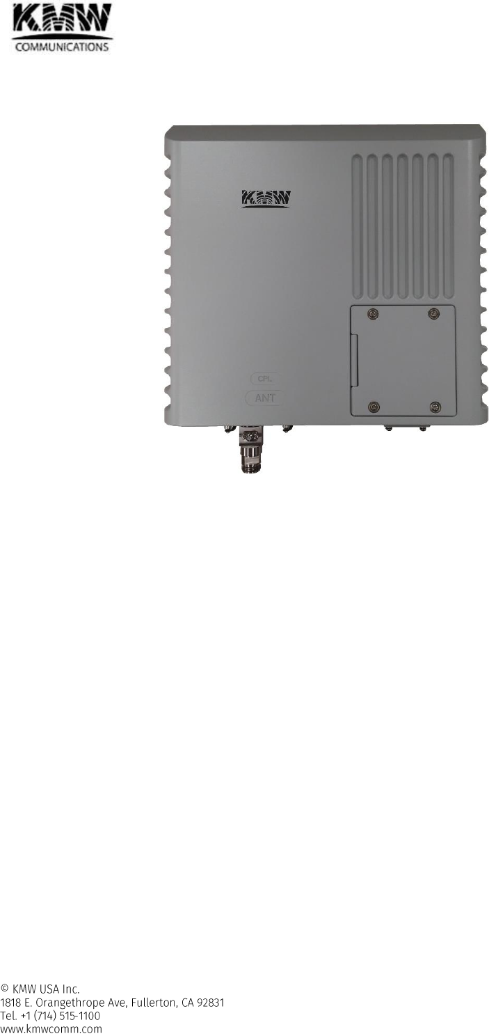
2.2.2 PS700/800 RU for public safety 700/800 frequency band service (POD-R-P78-27-AC/DC)
Figure 2-58 Remote Unit – PS700/800
2.2.2.1 Functions and features
- Supported frequency band: Public Safety 700M & 800M
- VSWR measurement function for checking VSWR of the connected service antenna
- Built-in Test tone generator in order to check uplink path verification
- Increase scalability by supporting expansion RU
Connected between expansion RU and main RU through AUX DL/UL port by using RF cable
Expansion RU can be added, when it needs additional frequency band other than frequency bands
being used in main RU, or additional filter attenuation in the frequency band being used in main RU. In
the latter case, the frequency band which needs additional filter attenuation must be off in main RU
and replaced by the frequency band with strengthened filter attenuation in expansion RU.
2.2.2.2 Specifications
- Operating Temperature: -40~55C
- Input Power
AC type: 110V, 50-60 Hz
DC Type: -48V
- Power Consumption: <55W
- IP rating: IP65
- Cooling method: convection cooling
- Dimension: (WxHxD) 13 x 12.2 x 3.9 in (330 x 310 x 100mm)
- Weight: 22.5 lbs (10.2kg)
User Manual for POD Systems Revision: 0.9
67
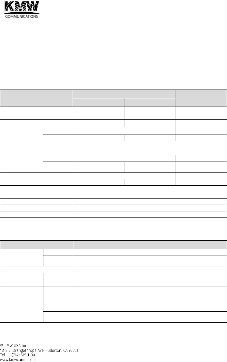
Table 2-36 PS700/800 RU - Specifications
PS700
PS800
Frequency Band
Downlink
758.0M - 775.0M
851M - 869M
Uplink
788.0M - 805.0M
806.0M - 824.0M
Bandwidth
17.0 MHz
18.0 MHz
Mean Gain
Downlink
36 ± 1.0 dB
36 ± 1.0 dB
Uplink
37 ± 1.0 dB
37 ± 1.0 dB
Maximum Gain
Downlink
67 dB
Uplink
37 dB
Ripple(p-p)
Downlink
3.5 dB @Full band
2.0 dB @759~774M
3.5 dB @Full band
2.0 dB @852~869M
Uplink
5.3 dB @Full band
2.0 dB @789~804M
5.3 dB @Full band
2.0 dB @807~824M
Maximum downlink output power
27 dBm
27 dBm
Uplink Noise Figure @center freq.
4.00 dB
4.00 dB
VSWR
< 1:1.7
Delay
< 5.00 us
EVM
< 5.0 % @E-TM 3.1
Operating band unwanted emissions
Meet FCC, LTE Repeater Spec.
Out of band emission
Meet FCC, LTE Repeater Spec.
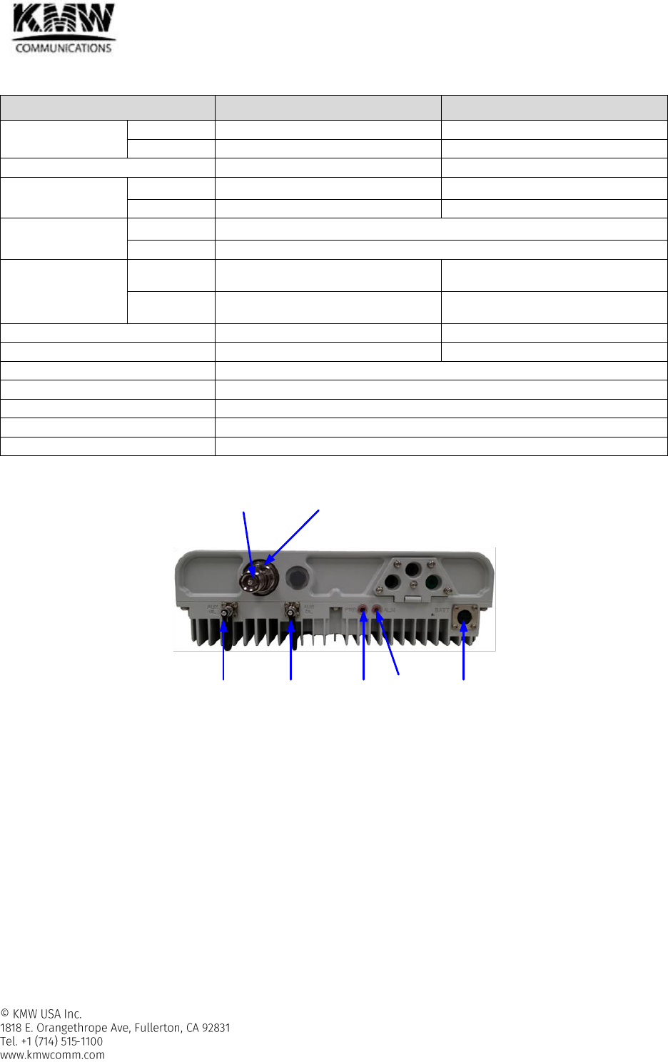
2.2.2.3 RF ports and LED
Figure 2-59 Remote Unit - PS700/800 External Interfaces
RF port
- ANT port
Connected to Service antenna
Mini DIN, female type
- CPL port
Can be connected to spectrum analyzer to monitor downlink spectrum without interrupting wireless
service
SMA female type
- AUX UL & DL
Connected to expansion remote unit
QMA female type
AUX UL
Port
AUX DL
Port
ALM
LED
PWR
LED
BATT
Port
ANT Port CPL Port
User Manual for POD Systems Revision: 0.9
68
- TDD sync port
Provides TDD sync signal which can be used to synchronize with TDD signal measuring equipment such
as spectrum analyzer.
QMA female type
LED
Table 2-37 7/5/3 band RU LED Operation
Specifications
PWR
Solid Green
When power is on.
Off
When power is off.
ALM
Off
When PS700/800 band RU has no alarms.
Solid Yellow
When PS700/800 band RU has minor alarm.
Solid Red
When PS700/800 band RU has major alarm.
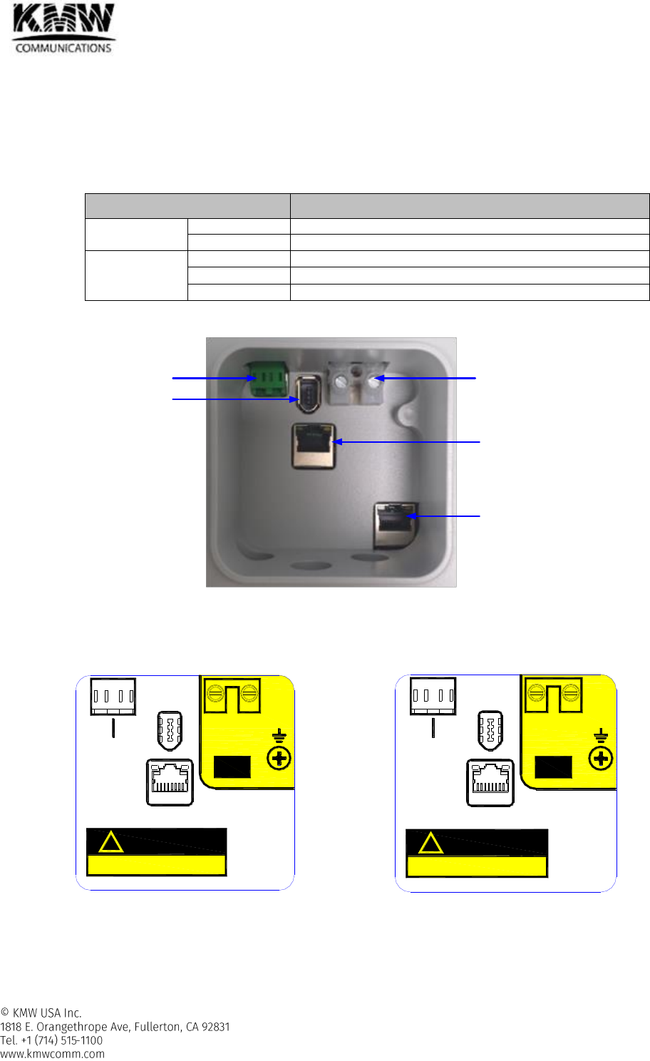
2.2.2.4 Debug Window
Figure 2-60 Debug Window
User can know the name for each port of RU by the sticker attached on the cover of debug window when user
opens debug window. User can verify whether RU is AC or DC type, and RU is main RU or expansion RU.
Main RU - AC type
Main RU - DC type
Optic Port AC or DC Power
input Port
Serial Port
Ethernet Port #1
Ethernet Port #2
GUI / EXT
DEBUG
UL DL
(OPTIC)
AC
(L) AC
(N)
AC
AC ONLY
CAUTION
!
DEBUG
GUI / EXT
UL DL
(OPTIC)
RTN
-48V
DC
DC ONLY
CAUTION
!

User Manual for POD Systems Revision: 0.9
69
Expansion RU - AC type
Expansion RU - DC type
Figure 2-61 Port name for each RU type
Optic port
- Connected to Head-end
- Expansion RU doesn’t need optic port because it is connected to main RU through RF cable.
- LC/APC Female type
- Wavelength: 1310nm for downlink, 1550nm for uplink
Serial port (DEBUG): Used for internal debug
AC or DC power input port
- AC or DC power source is provided into Remote unit through this port.
110V AC, 50~60Hz or DC -48V
CAUTION
Must verify whether remote unit is AC or DC type before connecting input power to AC or DC input port
because AC and DC power input port has same form factor.
It might cause severe damage of remote unit when user connects AC input to DC power input port of DC
type RU or DC input to AC power input port of AC type RU in the wrong way.
User can verify easily whether remote unit is AC or DC type by checking the picture of sticker attached
to the debug window cover when you open it. (refer to Figure 2-61)
Ethernet Port
- Ethernet Port #1
Used as GUI Port to access web-based GUI when expansion RU is not connected
Used for connecting to expansion RU when expansion RU is connected to main RU.
Use GUI port in expansion RU to access web-based GUI when expansion RU is connected
- Ethernet Port #2
Used as GUI Port to access web-based GUI for only expansion RU
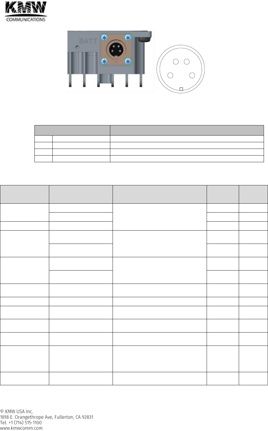
2.2.2.5 Battery Backup Port
GUI
AC
AC ONLY
CAUTION
!
AC
(L) AC
(N)
EXT
DEBUG
GUI
DC
DC ONLY
CAUTION
!
RTN
-48V
EXT
DEBUG
User Manual for POD Systems Revision: 0.9
70
Figure 2-62 Battery backup port
- Connected to rechargeable battery
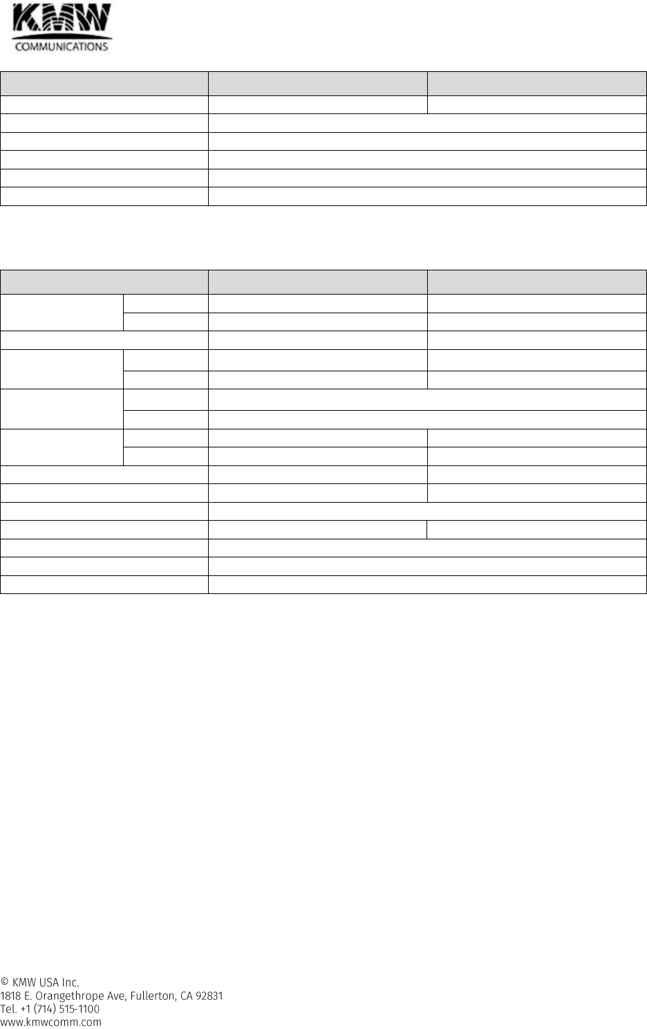
Table 2-38 Pin map - Battery Backup Port
Pin Assign
Specifications
1
DC
26V
2
DC
26V
3
GND
GND
4
GND
GND
2.2.2.6 Alarms
Table 2-39 PS700/800 band RU – Alarms
Alarm Name
Description
Remedy
Alarm
Severity
LED
color
High Temperature
Temperature too high
Check environment
Major
Red
Temperature high
Minor
Yellow
Low Temperature
Temperature too low
Minor
Yellow
Downlink High
Output Power
RF signal too high
Check Head-end downlink input level/
attenuator configuration/ ALC status
Major
Red
RF signal high
Major
Yellow
Uplink High Input
Power
RF signal too high
Check RU uplink input level/ attenuator
configuration/ ALC status
Major
Red
RF signal high
Major
Yellow
Downlink Low
Output Power
RF signal too low
Check Head-end downlink input level/
attenuator configuration/ RF cabling
Minor
Yellow
Link
Communication fail
Check cable connection
Major
Yellow
Freeze
The final stage of
Shutdown process
Check if shutdown process is going again
after reset
Major
Red
Downlink ALC
Activation
ALC activation
Check Head-end downlink input level/
attenuator configuration
Warning
Yellow
Uplink PLL Unlock
Uplink PLL unlock
Check if uplink PLL is still in unlocked
status after resetting PLL frequency
Minor
Yellow
VSWR
Bad RF cable/mismatched
service antenna
Check cable between RU and service
antenna, VSWR of service antenna
Major
Yellow
Optic LD Fail
Uplink LD fail
Check if optic LD fail alarm occurs again
after reset.
Major
Yellow
3 2
14

User Manual for POD Systems Revision: 0.9
71
Optic PD Fail
Downlink PD fail
Check optic cable connection with H-
HOM
Major
Yellow
Optic Loss
Excess permitted optic loss
Check optic cable connection with H-
HOM / clean Optic connector and port
Minor
Yellow
High current
Power supply load too high
Check if current alarm occurs again after
reset.
Critical
Red
2.2.2.7 Grounding
- Refer to section 3.3.2
User Manual for POD Systems Revision: 0.9
72
3. EQUIPMENT INSTALLATION
3.1 Inspection before equipment installation
Please follow these procedures before installing KMW POD equipments:
- Verify the number of packages received against the packing list.
- Check all packages for external damage; report any external damage to the shipping carrier.
- Open and check each package against the packing list. If any items are missing, contact KMW customer
service.
3.1.1 The Part list for each unit
3.1.1.1 Head-end Unit
3.1.1.1.1 POD-H-DMCU
Q’ty
Length
Comments
H-DMCU
1
H-CDU
1
Cable Duct Unit
Quick Installation Guide
1
Rack mount bracket
1
Power & signal cable between H-DMCU and H-PSU
1
30cm
Refer to section 4.1.1
Ethernet Cable for Web GUI or modem connection
1
2m
GND Cable
1
1m
3.1.1.1.2 POD-H-PSU
Q’ty
Length
Comments
H-PSU
1
Quick Installation Guide
1
Rack mount bracket
1
Power & signal cable between H-DMCU and H-PSU
1
2m
Refer to section 4.1.1
Ethernet Cable between H-DMCU and H-PSU
1
2m
GND Cable
1
1m
AC Cable (H-SPU-AC only)
1
2m
3.1.1.1.3 POD-H-SRU
Q’ty
Length
Comments
H-SRU
1
H-FAU
1
FAN Unit
Quick Installation Guide
1
Rack mount bracket
1
Power & signal cable between H-PSU and H-SRU
1
2m
Refer to section 4.1.1
Power & signal cable between H-SRU and H-FAU
1
2m
GND Cable
1
1m
3.1.1.1.4 POD-H-SCM
Q’ty
Length
Comments
H-SCM
1
Ethernet Cable between H-DMCU and H-SCM, or
between H-MCM and H-SCM
1
2m
Refer to section 4.1.1
3.1.1.1.5 POD-H-MCM
Q’ty
Length
Comments
H-MCM
1
Ethernet Cable between H-DMCU and H-MCM
1
2m
Refer to section 4.1.1

User Manual for POD Systems Revision: 0.9
73
3.1.1.2 Remote Unit
3.1.1.2.1 7/5/3 band RU, PS700/800 RU
Q’ty
Length
Comments
7/5/3 band RU or PS700/800 RU
1
Quick Installation Guide
1
wall mount bracket
1
AC or DC input power cable
1
2m
Refer to section 4.2.1.1
Ethernet Cable for Web GUI or modem connection
1
2m
GND Cable
1
2m
User Manual for POD Systems Revision: 0.9
74
3.2 Head-end Unit Equipment Installation
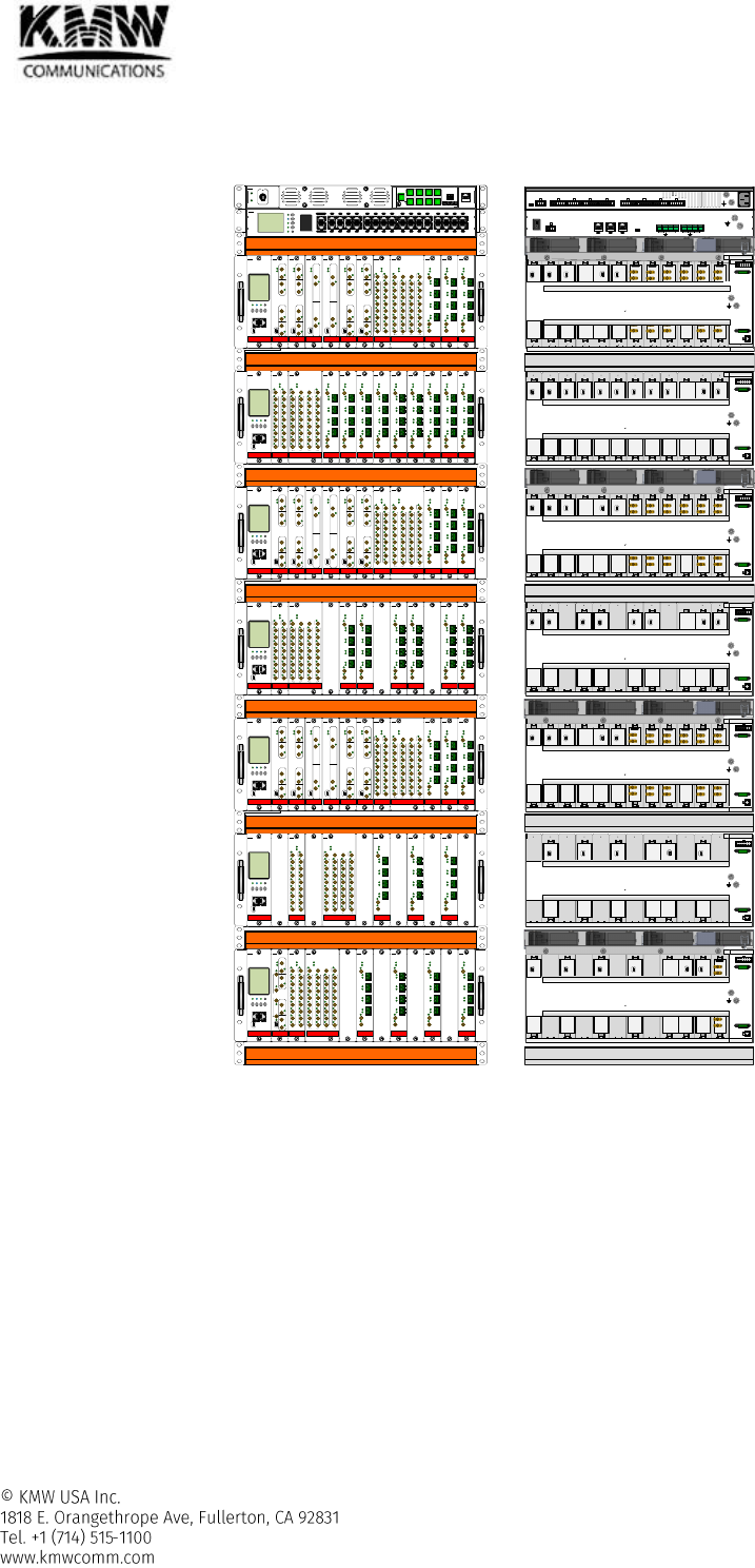
3.2.1 Installation Head-end Unit in a 19” rack
Figure 3-1 Head-end Unit Rack Mount (Front & Rear view)
1 2 3 4 5 6 7 8 9 10 11 12
ENT
Up
Down
ESC
Reset
Run
DMCU
Alarm
Link
HE
Alarm
RU
Alarm
1
2
3
4
5 7
6 8
9 11 13 15
10 12 14 16
17 19 21 23
18 20 22 24
25 27 29 31
26 28 30 32
Modem
Web GUI
KMW
DMCU
HPSU
Power
Alarm
#1 #2 #3 #4
#5 #6 #7 #8
DMCU
#1 #2 #3 #4
1 2 1 2
Group Rack
KMW
HFM-L-W
UL MON
DL MON
DL Out
UL In
UL MON
DL MON
DL Out
UL In
PWR
ALM
Path A
Path B
KMW
HFM-L-A
UL MON
DL MON
DL Out
UL In
UL MON
DL MON
DL Out
UL In
PWR
ALM
Path A
Path B
KMW
HFM-L-7
UL MON
DL MON
DL Out
UL In
UL Mon
DL MON
DL Out
UL In
PWR
ALM
Path A
Path B
KMW
HFM-L-C
UL MON
DL MON
DL Out
UL In
UL MON
DL MON
DL Out
UL In
PWR
ALM
Path A
Path B
KMW
HFM-L-P
DL Out
UL MON
UL In
DL MON
PWR
ALM
PCS
KMW
Run Link ALM Reset
ENT Up Down ESC
DMCU Web GUI
SCM
KMW
HCM-8
PWR
ALM
DL
COM
#1
#2
#3
#4
#5
#6
#7
#8
#1
#2
#3
#4
#5
#6
#7
#8
UL
COM
DL UL
KMW
HOM-L
PWR
ALM
UL Out
DL In
T_Sync
DL
UL
DL
UL
DL
UL
DL
UL
KMW
# 1
# 2
# 3
# 4
1 2 3 4 5 6 7 8 9 10 11 12
HOM-L
PWR
ALM
UL Out
DL In
T_Sync
DL
UL
DL
UL
DL
UL
DL
UL
KMW
# 1
# 2
# 3
# 4
HOM-L
PWR
ALM
UL Out
DL In
T_Sync
DL
UL
DL
UL
DL
UL
DL
UL
KMW
# 1
# 2
# 3
# 4
DTM-8X8
PWR
ALM
KMW
VHF
UHF
#1
#2
#3
#4
#5
#6
#7
#8
#1
#2
#3
#4
#5
#6
#7
#8
DL MON
DL UL
UL MON
#1
#2
#3
#4
#5
#6
#7
#8
#1
#2
#3
#4
#5
#6
#7
#8
VHF
UHF
IN OUT IN OUT
HFM-L-P
DL Out
UL MON
UL In
DL MON
PWR
ALM
PCS
KMW
1 2 3 4 5 6 7 8 9 10 11 12
HCM-8
PWR
ALM
DL
COM
#1
#2
#3
#4
#5
#6
#7
#8
#1
#2
#3
#4
#5
#6
#7
#8
UL
COM
DL UL
KMW
DTM-8X8
PWR
ALM
KMW
VHF
UHF
#1
#2
#3
#4
#5
#6
#7
#8
#1
#2
#3
#4
#5
#6
#7
#8
DL MON
DL UL
UL MON
#1
#2
#3
#4
#5
#6
#7
#8
#1
#2
#3
#4
#5
#6
#7
#8
VHF
UHF
IN OUT IN OUT
Run Link ALM Reset
ENT Up Down ESC
DMCU Web GUI
SCM
KMW
HOM-L
PWR
ALM
UL Out
DL In
T_Sync
DL
UL
DL
UL
DL
UL
DL
UL
KMW
# 1
# 2
# 3
# 4
HOM-L
PWR
ALM
UL Out
DL In
T_Sync
DL
UL
DL
UL
DL
UL
DL
UL
KMW
# 1
# 2
# 3
# 4
HOM-L
PWR
ALM
UL Out
DL In
T_Sync
DL
UL
DL
UL
DL
UL
DL
UL
KMW
# 1
# 2
# 3
# 4
Run Link ALM Reset
ENT Up Down ESC
DMCU Web GUI
SCM
KMW
HCM-8
PWR
ALM
DL
COM
#1
#2
#3
#4
#5
#6
#7
#8
#1
#2
#3
#4
#5
#6
#7
#8
UL
COM
DL UL
KMW
HOM-L
PWR
ALM
UL Out
DL In
T_Sync
DL
UL
DL
UL
DL
UL
DL
UL
KMW
# 1
# 2
# 3
# 4
1 2 3 4 5 6 7 8 9 10 11 12
HOM-L
PWR
ALM
UL Out
DL In
T_Sync
DL
UL
DL
UL
DL
UL
DL
UL
KMW
# 1
# 2
# 3
# 4
HOM-L
PWR
ALM
UL Out
DL In
T_Sync
DL
UL
DL
UL
DL
UL
DL
UL
KMW
# 1
# 2
# 3
# 4
HOM-L
PWR
ALM
UL Out
DL In
T_Sync
DL
UL
DL
UL
DL
UL
DL
UL
KMW
# 1
# 2
# 3
# 4
DTM-8X8
PWR
ALM
KMW
VHF
UHF
#1
#2
#3
#4
#5
#6
#7
#8
#1
#2
#3
#4
#5
#6
#7
#8
DL MON
DL UL
UL MON
#1
#2
#3
#4
#5
#6
#7
#8
#1
#2
#3
#4
#5
#6
#7
#8
VHF
UHF
IN OUT IN OUT
HFM-L-B
UL MON
DL MON
DLOut
UL In
UL MON
DL MON
DL Out
UL In
PWR
ALM
Path A
Path B
#1
#2
#3
#4
T-Sync
KMW
HOM-L
PWR
ALM
UL Out
DL In
T_Sync
DL
UL
DL
UL
DL
UL
DL
UL
KMW
# 1
# 2
# 3
# 4
HOM-L
PWR
ALM
UL Out
DL In
T_Sync
DL
UL
DL
UL
DL
UL
DL
UL
KMW
# 1
# 2
# 3
# 4
HOM-L
PWR
ALM
UL Out
DL In
T_Sync
DL
UL
DL
UL
DL
UL
DL
UL
KMW
# 1
# 2
# 3
# 4
HOM-L
PWR
ALM
UL Out
DL In
T_Sync
DL
UL
DL
UL
DL
UL
DL
UL
KMW
# 1
# 2
# 3
# 4
HOM-L
PWR
ALM
UL Out
DL In
T_Sync
DL
UL
DL
UL
DL
UL
DL
UL
KMW
# 1
# 2
# 3
# 4
HOM-L
PWR
ALM
UL Out
DL In
T_Sync
DL
UL
DL
UL
DL
UL
DL
UL
KMW
# 1
# 2
# 3
# 4
HOM-L
PWR
ALM
UL Out
DL In
T_Sync
DL
UL
DL
UL
DL
UL
DL
UL
KMW
# 1
# 2
# 3
# 4
HOM-L
PWR
ALM
UL Out
DL In
T_Sync
DL
UL
DL
UL
DL
UL
DL
UL
KMW
# 1
# 2
# 3
# 4
HOM-L
PWR
ALM
UL Out
DL In
T_Sync
DL
UL
DL
UL
DL
UL
DL
UL
KMW
# 1
# 2
# 3
# 4
HPSU
Power SW
DMCU
1 2 3
External Alarm
Input Output
1 2 3 4 5 6 7 8
#1 #2 #3 #4 #5 #6 #7 #8
DMCU HSRU
1 2 3 4 5 6 7 8 9 10 11 12
DL / UL (A)
UL Div (A)
DL / UL (B)
UL Div (B)
700M
┌
┌
└
└
DL / UL (A)
UL Div (A)
DL / UL (B)
UL Div (B)
850M
┌
┌
└
└
DL / UL (A)
UL Div (A)
DL / UL (B)
UL Div (B)
AWS
┌
┌
└
└
DL / UL (A)
UL Div (A)
PCS
┌
┌
DL / UL (A)
UL Div (A)
DL / UL (B)
UL Div (B)
WCS
┌
┌
└
└
DL / UL (A)
UL Div (A)
DL / UL (B)
UL Div (B)
WCS
┌
┌
└
└
- 30 -
- 30 -
#12 #11 #10 #9 #8 #7 #6 #5 #4 #3 #2 #1
HPSU
FUSE
Spare Fuse
FAN
- 30 -
- 30 -
#12 #11 #10 #9 #8 #7 #6 #5 #4 #3 #2 #1
HPSU
FUSE
Spare Fuse
FAN
DL / UL (A)
UL Div (A)
DL / UL (B)
UL Div (B)
WCS
┌
┌
└
└
1 2 3 4 5 6 7 8 9 10 11 12
DL / UL (A)
UL Div (A)
DL / UL (B)
UL Div (B)
700M
┌
┌
└
└
DL / UL (A)
UL Div (A)
DL / UL (B)
UL Div (B)
850M
┌
┌
└
└
DL / UL (A)
UL Div (A)
DL / UL (B)
UL Div (B)
AWS
┌
┌
└
└
DL / UL (A)
UL Div (A)
PCS
┌
┌
DL / UL (A)
UL Div (A)
DL / UL (B)
UL Div (B)
WCS
┌
┌
└
└
- 30 -
- 30 -
#12 #11 #10 #9 #8 #7 #6 #5 #4 #3 #2 #1
HPSU
FUSE
Spare Fuse
FAN
DL / UL (A)
UL Div (A)
DL / UL (B)
UL Div (B)
700M
┌
┌
└
└
- 30 -
- 30 -
#12 #11 #10 #9 #8 #7 #6 #5 #4 #3 #2 #1
HPSU
FUSE
Spare Fuse
FAN
1 2 3 4 5 6 7 8 9 10 11 12
DL / UL (A)
UL Div (A)
DL / UL (B)
UL Div (B)
WCS
┌
┌
└
└
- 30 -
- 30 -
#12 #11 #10 #9 #8 #7 #6 #5 #4 #3 #2 #1
HPSU
FUSE
Spare Fuse
FAN
1 2 3 4 5 6 7 8 9 10 11 12
DL / UL (A)
UL Div (A)
DL / UL (B)
UL Div (B)
700M
┌
┌
└
└
DL / UL (A)
UL Div (A)
DL / UL (B)
UL Div (B)
850M
┌
┌
└
└
DL / UL (A)
UL Div (A)
DL / UL (B)
UL Div (B)
AWS
┌
┌
└
└
DL / UL (A)
UL Div (A)
PCS
┌
┌
DL / UL (A)
UL Div (A)
DL / UL (B)
UL Div (B)
WCS
┌
┌
└
└
- 30 -
- 30 -
#12 #11 #10 #9 #8 #7 #6 #5 #4 #3 #2 #1
HPSU
FUSE
Spare Fuse
FAN
- 30 -
- 30 -
#12 #11 #10 #9 #8 #7 #6 #5 #4 #3 #2 #1
HPSU
FUSE
Spare Fuse
FAN
User Manual for POD Systems Revision: 0.9
75
CAUTIONS AND CONSIDERATIONS
- POD Head-end system should be installed inside building only and mounts in a standard 19” rack.
- The rule for installing FAN unit: refer to section -
- Allowed minimum clearance
Front and Rear: 10” (254mm)
Both sides:2” (51mm)
Top and bottom: No clearance is required.
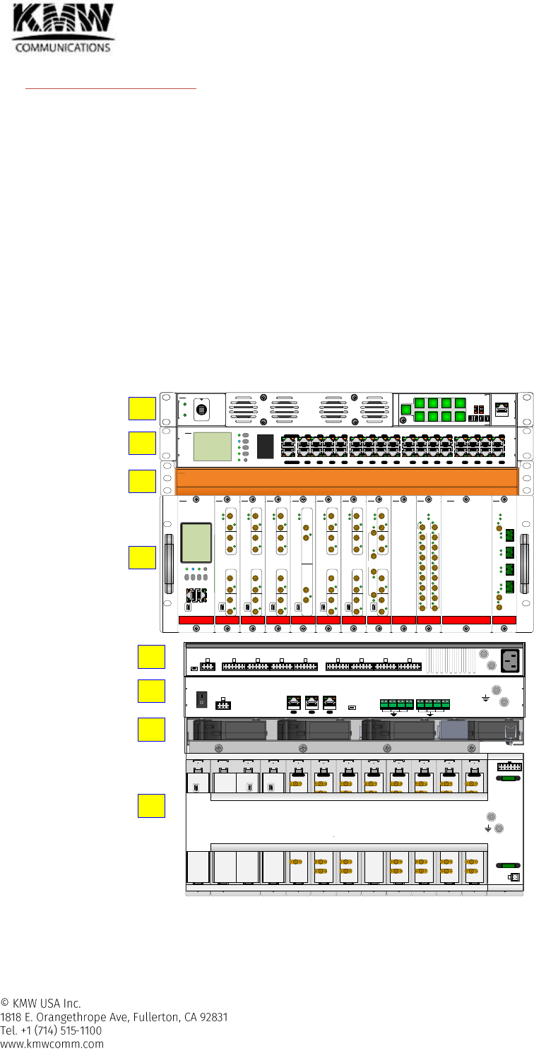
3.2.1.1 The sequence for mounting head-end unit
The sequence for mounting each head-end unit is as below.
- (1)H-PSU → (2)H-DMCU →(3-1)H-CDU #1 →(4-1)H-SRU #1 … (3-7)H-CDU #7 →(4-7)H-SRU #7 →(5)H-FAU
H-PSU must be installed at the top of the rack.
H-DMCU must be installed right below H-PSU on the rack.
H-SRU must be installed below H-DMCU with skip 1U gap
H-CDU must be installed between H-DMCU and H-SRU.
H-FAU (FAN Unit) will be installed in the empty space from rear side of H-CDU (Cable duck Unit).
- Regarding FAN installation, refer to section -.
Figure 3-2 Head-end Unit - Rack Mount Sequence
FEM-L-W
UL MON
DL MON
DL Out
UL In
UL MON
DL MON
DL Out
UL In
PWR
ALM
Path A
Path B
KMW
FEM-L-A
UL MON
DL MON
DL Out
UL In
UL MON
DL MON
DL Out
UL In
PWR
ALM
Path A
Path B
KMW
FEM-L-7
UL MON
DL MON
DL Out
UL In
UL Mon
DL MON
DL Out
UL In
PWR
ALM
Path A
Path B
KMW
FEM-L-S8
UL MON
DL MON
DL Out
UL In
UL MON
DL MON
DL Out
UL In
PWR
ALM
Path A
Path B
KMW
FEM-L-C
UL MON
DL MON
DL Out
UL In
UL MON
DL MON
DL Out
UL In
PWR
ALM
Path A
Path B
KMW
FEM-L-B
UL MON
DL MON
DLOut
UL In
UL MON
DL MON
DL Out
UL In
PWR
ALM
Path A
Path B
#1
#2
#3
#4
T-Sync
KMW
FEM-L-P
DL Out
UL MON
UL In
DL MON
PWR
ALM
PCS
KMW
Run Link ALM Reset
ENT Up Down ESC
DMCU Web GUI
SCM
KMW
COM-8
PWR
ALM
DL
COM
#1
#2
#3
#4
#5
#6
#7
#8
#1
#2
#3
#4
#5
#6
#7
#8
UL
COM
DL UL
KMW
HOM-L
PWR
ALM
UL Out
DL In
T_Sync
DL
UL
DL
UL
DL
UL
DL
UL
KMW
# 1
# 2
# 3
# 4
BLANK
KMW
BLANK
KMW
1 2 3 4 5 6 7 8 9 10 11 12
KMW
ENT
Up
Down
ESC
Reset
Run
DMCU
Alarm
Link
HE
Alarm
RU
Alarm
1
2
3
4
5 7
6 8
9 11 13 15
10 12 14 16
17 19 21 23
18 20 22 24
25 27 29 31
26 28 30 32
Modem
Web GUI
KMW
DMCU
HPSU
Power
Alarm
#1 #2 #3 #4
#5 #6 #7 #8
DMCU
#1 #2 #3 #4
1 2 1 2
Group Rack
KMW
1
2
3-1
4-1
DL / UL (A)
UL Div (A)
DL / UL (B)
UL Div (B)
700M
┌
┌
└
└
DL / UL (A)
UL Div (A)
DL / UL (B)
UL Div (B)
P7/P8
┌
┌
└
└
DL / UL (A)
UL Div (A)
DL / UL (B)
UL Div (B)
S8
┌
┌
└
└
DL / UL (A)
UL Div (A)
DL / UL (B)
UL Div (B)
850M
┌
┌
└
└
DL / UL (A)
UL Div (A)
PCS
┌
┌
DL / UL (A)
UL Div (A)
DL / UL (B)
UL Div (B)
AWS
┌
┌
└
└
DL / UL (A)
UL Div (A)
DL / UL (B)
UL Div (B)
WCS
┌
┌
└
└
DL / UL (A)
DL / UL (B)
BRS
┌
└
- 30 -
- 30 -
#12 #11 #10 #9 #8 #7 #6 #5 #4 #3 #2 #1
HPSU
FUSE
Spare Fuse
FAN
HPSU
Power SW
DMCU
1 2 3
External Alarm
Input Output
1 2 3 4 5 6 7 8
#1 #2 #3 #4 #5 #6 #7 #8
DMCU HSRU
1
2
5
4-1
User Manual for POD Systems Revision: 0.9
76
3.2.2 Grounding
The grounding terminals are located at the rear of H-PSU, H-DMCU, and H-SRU. They must be grounded properly
before powering on the equipment.
Figure 3-10 Head-end units Grounding
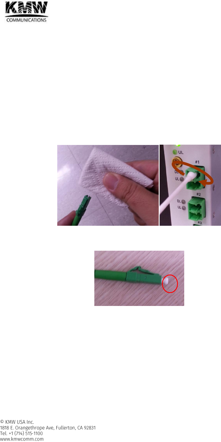
3.2.3 Optic port Cleaning
We recommend that optic connector should be cleaned using a dry optical cleaning swab or tissue in a dry
environment before connecting optic cable. Also, if the expected optic loss is 1.5dB higher than the loss
reported in the Web-GUI, the optic loss should be minimized through cleaning optic connectors.(Figure 3-3)
The unused optic ports are should be covered with a protective dust cap. (Figure 3-4)
Figure 3-3 Optic Connector Cleaning (left) and Optic Port Cleaning (right)
Figure 3-4 LC/APC Optic Connector Dust Cap
User Manual for POD Systems Revision: 0.9
77
3.3 Remote Unit
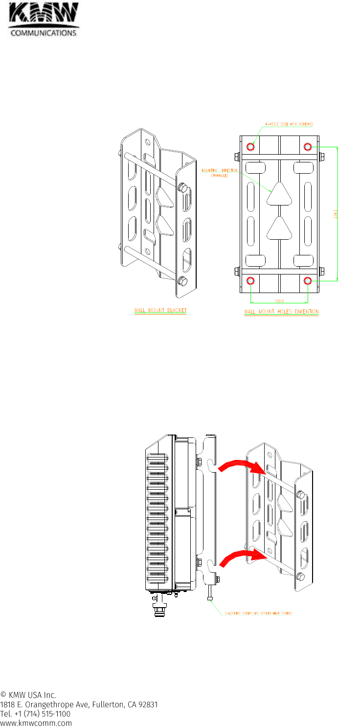
3.3.1 Wall Mount for 3/5/7 band RU and PS700/800 RU
Wall mounting procedure
- Check the suitability of the wall-mounting kit and the wall based on Figure 3-5
Figure 3-5 3/5/7 band RU, PS700/800 RU – wall mount bracket
- Install the wall-mounting bracket using 4 x M10 screw anchors (not included**) according to the drilling
layout. Confirm that the bracket is securely fastened to the wall.
** The M10 screw anchors are not included as part of the RU delivery because the suitable type
depends on the on-site conditions such as wall structure and materials. Therefore, use screw anchors
that are appropriate for the mounting surface.
- Install the Remote Unit on the wall-mounting bracket by lifting the RU into place and lowering it down onto
the bracket. The M6 pins must align with the slots in the bracket to support the RU.
Figure 3-6 3/5/7 band RU, PS700/800 RU – Install RU into wall mount bracket
- Fasten the lower section of the Remote Unit to the bracket using a washer and 2 x M6 screws (on both
sides). Slide a washer over each screw and then insert the screw and tighten it securely.
User Manual for POD Systems Revision: 0.9
78
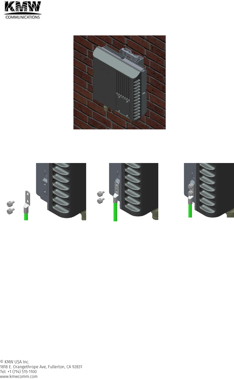
- Confirm that all screws have been fastened and the unit is securely mounted to the wall.
Figure 3-7 3/5/7 band RU, PS700/800 RU – RU installed on the wall
3.3.2 Grounding
3.3.2.1 3/5/7 band RU, PS700/800 RU
Step A
Step B
Step C
Figure 3-8 3/5/7 band RU grounding
- Connect an earth-bonding cable to the grounding bolt connection provided on the outside of the remote
unit (Left-side) as shown in Figure 3-8. Do not use earth-bonding cable to connect other external devices.
loosen the two hex bolts attached to remote unit as illustrated in Figure 3-8, Step A
Connect the earth-bonding cable to remote unit as illustrated in Figure 3-8, Step B
Then, fasten all parts again by tightening the hex bolts as illustrated in Figure 3-8, Step C
- Connect the other end of the ground wire to a suitable permanent ground following local electrical code
practices.
User Manual for POD Systems Revision: 0.9
79
4. CABLE CONNECTION
4.1 Head-end Unit Cable Connection
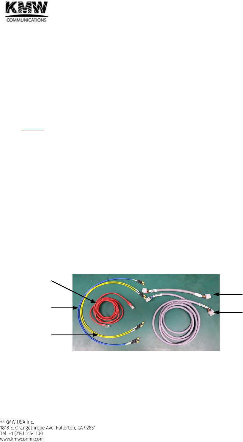
4.1.1 Cable
RF Cable
- Between modules in H-SRU or between H-SRUs
Downlink
Connector: SMB-L, female
Cable Color: Blue Jacket
Uplink
Connector: SMB-L, female
Cable Color: Yellow Jacket
- CAUTION) RF cable with 35” length will be provided normally. 60” and 90” RF cable can be provided by user’s
special order.
Ethernet cable
- Between H-DMCU and H-SCM or H-PSU
Connector: RJ45, female
Length: 2m
Power & Signal cable
- Between H-DMCU and H-PSU
Length: 30cm
- Between H-SRU and H-PSU
Length: 2m
- Between H-SRU and H-FAU
Length: 40cm
- AC Power Cable
Length: 2m
GND Cable
- H-DMCU, H-PSU, H-SRU
Length: 1m
Figure 4-1 Head-end - cables
Downlink
RF cable
Uplink
RF cable
Ethernet
Cable H-DMCU~
H-PSU
H-SRU~
H-PSU
User Manual for POD Systems Revision: 0.9
80
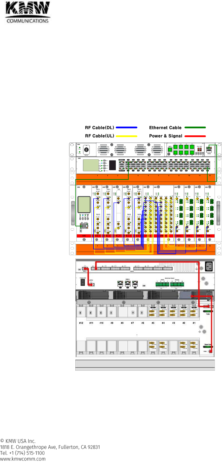
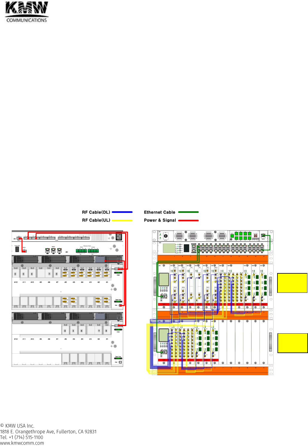
4.1.2 Cable Connection Example for frequency bands with FDD type
POD DAS System configuration
- H-DMCU : 1ea
- H-PSU: 1ea
- H-SRU: 1ea (H-SCM, H-FAU, H-CDU)
- H-FEM: 5ea (FEM-L-7, FEM-L-C, FEM-L-P, FEM-L-A, FEM-L-W)
- H-COM: 1ea
- H-DTM: 1ea
- H-HOM-L: 4ea
Figure 4-2 shows cable connection example for frequency bands with FDD type.
Figure 4-2 Cable Connection Example for frequency bands with FDD type

User Manual for POD Systems Revision: 0.9
81
RF cable connection
- The RF ports for BTS connection are located in the back of H-SRU.
- All RF ports for the connection between modules installed in H-SRU are located in the front of H-SRU.
Optic cable connection
- The optic ports for the connection with Remote units are located in the front panel of H-HOM-L.
Ethernet cable connection
From
To
Comments
Ethernet cable
H-DMCU
H-SCM
H-DMCU
H-PSU
Power & signal cable connection
From
To
Comments
Power & Signal cable
H-PSU
H-DMCU
H-PSU
H-SRU
H-SRU
H-FAU
User Manual for POD Systems Revision: 0.9
82
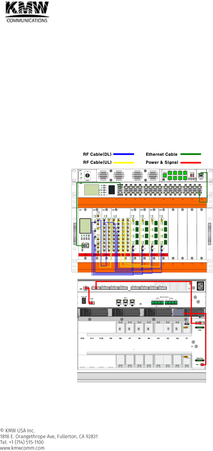
4.1.3 Cable Connection for TDD 2.6G frequency band
POD DAS System configuration
- H-DMCU : 1ea
- H-PSU: 1ea
- H-SRU: 1ea (H-SCM, H-FAU, H-CDU)
- H-FEM: 1ea (FEM-L-B)
- H-COM: 1ea
- H-DTM: 1ea
- H-HOM-L: 4ea
Figure 4-3 shows cable connection example for TDD 2.6G frequency band.
In case of 2.6G supporting TDD system, TDD sync signal generated from H-FEM-L-B should be transferred to RU
to synchronize TDD timing in overall POD DAS system. H-FEM-L-B has 4 TDD sync output port and each TDD sync
port is connected to TS sync port of H-HOM-L to transfer TDD signal over optic cable.
Figure 4-3 Cable Connection Example #1 for TDD 2.6G frequency band
User Manual for POD Systems Revision: 0.9
83
RF cable connection
- The RF ports for BTS connection are located in the back of H-SRU.
- All RF ports for the connection between modules installed in H-SRU are located in the front of H-SRU.
RF cable connection for TDD sync signal transfer
From
To
Module
port
Module
port
RF cable
H-FEM-L(H)-B
T-Sync #1~#4
H-HOM
T_Sync
Optic cable connection
- The optic ports for the connection with Remote units are located in the front panel of H-HOM-L.
Ethernet cable connection
From
To
Comments
Ethernet cable
H-DMCU
H-SCM
H-DMCU
H-PSU
Power & signal cable connection
From
To
Comments
Power & Signal cable
H-PSU
H-DMCU
H-PSU
H-SRU
H-SRU
H-FAU
User Manual for POD Systems Revision: 0.9
84
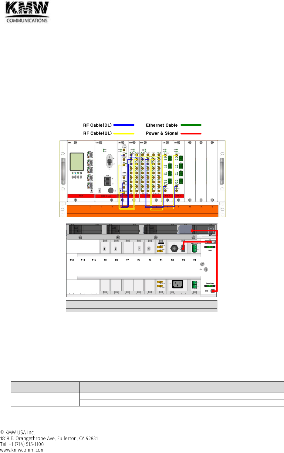
4.1.4 Cable Connection Example for Public Safety 700/800 band
POD DAS System configuration
- H-MCM : 1ea (or H-DMCU)
- H-PSM-OI: 1ea (or H-PSU)
- H-SRU: 1ea (H-SCM, H-FAU, H-CDU)
- H-FEM: 1ea (FEM-L-P7/P8)
- H-COM: 1ea
- H-DTM: 1ea
- H-HOM-L: 2ea
Figure 4-4 shows cable connection example for Public Safety 700/800 band.
Figure 4-4 Cable Connection Example for Public Safety 700/800 band
RF cable connection
- The RF ports for BTS connection are located in the back of H-SRU.
- All RF ports for the connection between modules installed in H-SRU are located in the front of H-SRU.
Optic cable connection
- The optic ports for the connection with Remote units are located in the front panel of H-HOM-L.
Power & signal cable connection
From
To
Comments
Power & Signal cable
H-PSM
H-SRU
H-SRU
H-FAU
User Manual for POD Systems Revision: 0.9
85
4.1.5 Cable Connection Example for MIMO configuration
POD DAS System configuration
- H-DMCU : 1ea
- H-PSU: 1ea
- H-SRU: 2ea (H-SCM, H-FAU, H-CDU)
- H-FEM: 6ea (H-FEM-L-7, H-FEM-L-C, H-FEM-L-P x2, H-FEM-L-A, H-FEM-L-W)
H-FEM-L-7, H-FEM-L-C, H-FEM-L-A, and H-FEM-L-W can support MIMO configuration by using one H-
FEM-L module because they have two paths in one module.
H-FEM-L-P supports only one path in one module. 2 H-FEM-L-P are needed to support MIMO
configuration for PCS frequency band.
- H-COM: 1ea
- H-DTM: 1ea
- H-HOM-L: 3ea
Figure 4-5 shows cable connection example for MIMO configuration.
MIMO #1
- H-FEM-L-x in H-SRU #1
- H-COM, H-DTM, and H-HOM-L in H-SRU #1
MIMO #2
- H-FEM-L-x in H-SRU #1
- H-COM, H-DTM, and H-HOM-L in H-SRU #2
Figure 4-5 Cable Connection for FDD frequency band (MIMO) support
H-SRU #1
H-SRU #2
User Manual for POD Systems Revision: 0.9
86
RF cable connection
- The RF ports for BTS connection are located in the back of H-SRU.
- All RF ports for the connection between modules installed in H-SRU are located in the front of H-SRU.
- RF cable connection For MIMO #1
H-FEM-L-x in H-SRU #1H-COM in H-SRU #1 H-DTM in H-SRU #1H-HOM-L in H-SRU #1
- RF cable connection For MIMO #2
H-FEM-L-x in H-SRU #1H-COM in H-SRU #2 H-DTM in H-SRU #2H-HOM-L in H-SRU #2
Optic cable connection
- The optic ports for the connection with Remote units are located in the front panel of H-HOM-L.
Ethernet cable connection
From
To
Comments
Ethernet cable
H-DMCU
H-SCM in H-SRU #1
H-DMCU
H-SCM in H-SRU #2
H-DMCU
H-PSU
Power & signal cable connection
From
To
Comments
Power & Signal cable
H-PSU
H-DMCU
H-PSU
H-SRU #1
H-PSU
H-SRU #2
H-SRU
H-FAU in H-SRU #1
User Manual for POD Systems Revision: 0.9
87
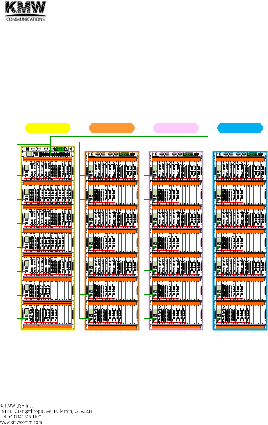
4.1.6 Cable connection between multiple Racks
Figure 4-6 shows how to connect cable and set rack ID for IP setting.
One H-DMCU is able to control and monitor maximum up to 4 racks and one rack can be composed of
maximum 7 H-SRUs and one H-DMCU. All H-PSU, H-SCM, and H-MCM are connected to H-DMCU through 32
Ethernet ports located in front side of H-DMCU.
Rack ID can be set by dip switch in H-PSU.
- Refer to section 2.1.12.7 to figure out how to set Rack ID.
It might need longer RF cable than RF cable with 35”length included in the packaged box for the connection
between racks. In this case, user needs to buy extra cable with longer length in advance. For your information,
RF cable with 60”, and 90” length can be provided by user’s special order.
Figure 4-6 Connection Diagram for Rack Inter Connection
Rack ID : #3Rack ID : #1 Rack ID : #4Rack ID : #2
Sub-Rack
#1
Sub-Rack
#2
Sub-Rack
#3
Sub-Rack
#4
Sub-Rack
#5
Sub-Rack
#6
Sub-Rack
#7

User Manual for POD Systems Revision: 0.9
88
4.2 Remote Unit Cable Connection
4.2.1 7/5/3 band & PS700/800 RU
4.2.1.1 Cable
Ethernet cable
- For web GUI connection or connection with expansion RU
Connector: RJ45, female
Length: 2m
AC or DC Power cable
- Length: 2m
GND Cable
- Length: 2m
User Manual for POD Systems Revision: 0.9
89
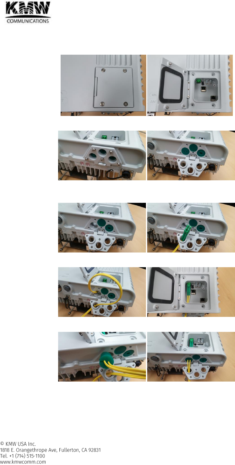
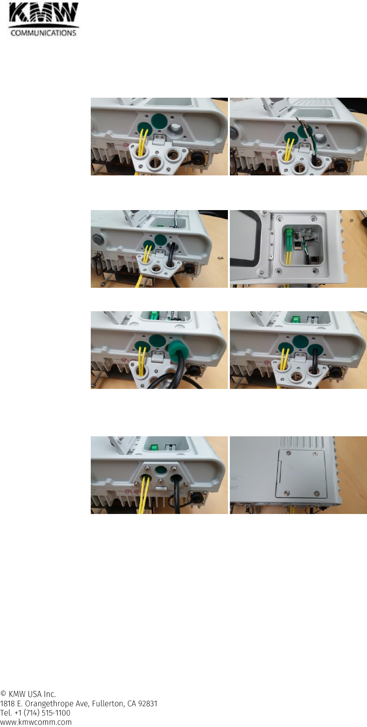
4.2.1.2 Optic cable connection
- After loosening 4x SECURITY SCREWS (M4), open the door for debug window.
- After loosening 5x SECURITY SCREWS (M4), open front door.
- After taking out of gasket from optic cable entrance located in left side, pass optic cable through this
entrance.
- Connect optic cable to optic port located on the left top side in debug window.
- Replace gasket into optic cable entrance.
- Continue in section 4.2.1.3.
User Manual for POD Systems Revision: 0.9
90
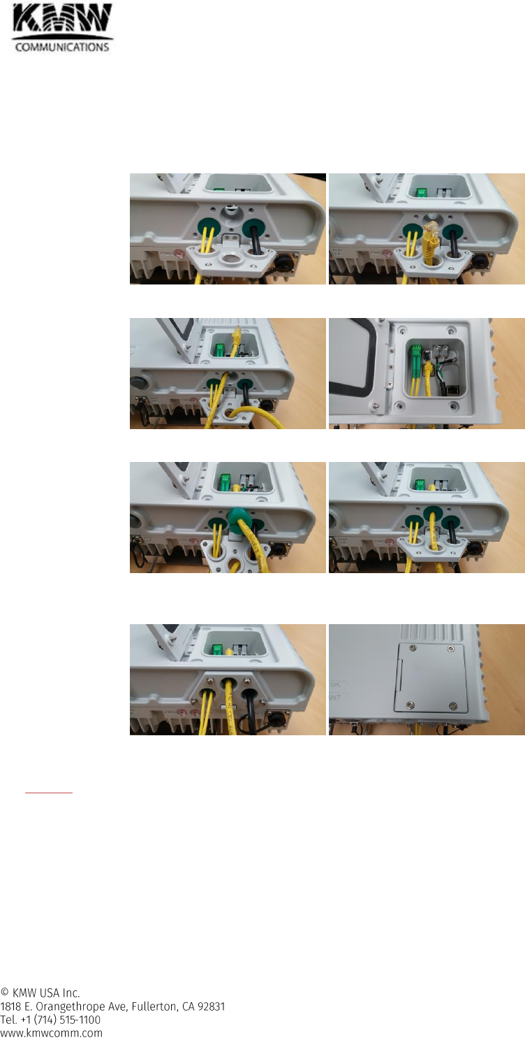
4.2.1.3 AC or DC power cable connection
- After taking out of gasket from power cable entrance located in right side, pass power cable through this
entrance.
- Connect power cable to AC (or DC) power terminal. In case of AC power cable, fasten ground cable by using
GND SCREW to GND position located on the right top side in debug window.
- Replace gasket into power cable entrance.
- If there is no expansion RU connected main RU, close/fasten the door for debug window and front door by
using SECURITY SCREWS (M4) and allowed Torque: 12.0 Kgfcm.
- If there is an expansion RU connected main RU, continue in section 4.2.1.4.
User Manual for POD Systems Revision: 0.9
91
4.2.1.4 Ethernet cable connection for connecting with Expansion RU
If there is an expansion RU connected main RU, connect Ethernet cable with expansion RU before closing the
door for debug window and front door.
- After taking out of gasket from Ethernet cable entrance located in the middle, pass Ethernet cable through
this entrance.
- Connect Ethernet cable to EXT port (RJ 45).
- Replace gasket into Ethernet cable entrance.
- Close/fasten the door for debug window and front door by using SECURITY SCREWS (M4) and allowed
Torque: 12.0 Kgfcm.
- Connect the other side of Ethernet cable to EXT pot of expansion RU based on section 4.2.1.4.
CAUTION) The location of EXT pot in expansion RU is different from the location of EXT port in main RU. Make
sure where the location of EXT port in expansion RU is (refer to Figure 2-57) before connecting Ethernet cable to
expansion RU.
User Manual for POD Systems Revision: 0.9
92
5. SPECIFICATION
5.1 Electrical Specifications (Low power HFM – Low power RU)
Table 5-1 POD DAS 2-Band RU Electrical Specifications (POD-R-P78-27-AC/DC)
Parameter
Specifications
Remark
PS 700
PS 800
Frequency
DL
758 - 775M
851 - 869M
UL
788 - 805M
806 - 824M
Input
DL
-40 ~ 20dBm
UL
-42dBm
-42dBm
Maximum
Output
DL
27dBm
@all temperature range
UL
-5dBm
@all temperature range
Gain Range
DL
7dB to 67dB
UL
-8dB to 37dB
Noise Figure @Max Gain
< 6 dB
@1 RU, optic loss: 0dB
Input/output Impedance
50 ohm
VSWR
< 1:1.7
System Delay
< 2us @2.6G, < 5us @other bands
Permitted optic loss
HOM-L: ~7.5dBo, HOM-H/OEM/OIM: ~10.5dBo
Frequency Error & EVM (LTE)
Frequency Error: <±0.01ppm, EVM: < 5%
Frequency Error & Rho (CDMA)
Frequency Error: <±0.05ppm, Rho: >0.912
Out of Band Emission
-13dBm/1KHz @9KHz – 150KHz
-13dBm/10KHz @150KHz – 30MHz
-13dBm/100KHz @30MHz – 1GHz
-13dBm/1MHz @1GHz – 12.75GHz
Operating Band
Unwanted
Emissions
CDMA
-45dBc/30KHz @±885KHz, -45dBc/30KHz @±1.125MHz
-50dBc/30KHz @±1.98MHz,
<-13dBm/30KHz @±2.25MHz, <-13dBm/1MHz @±4.0MHz
WCDMA/LTE
Meet 3GPP WCDMA/LTE Repeater Spec.
2 tone CW Test
Downlink: > 40dBc, Uplink: > 50dBc @two CW tone 1MHz separation
Operating
Temperature
Head-end
-10 ~ +50°C
RU
-40 ~ +55°C
Operating Humidity
≤ 95%, non-condensing
RU Enclosure
Meet IP65, NEMA4X
User Manual for POD Systems Revision: 0.9
93
Table 5-2 POD DAS 7-Band RU Electrical Specifications (POD-R-7S8CPAWB-2730-AC/DC)
Parameter
Specifications
Remark
700M
SMR 800 +
850M
PCS
AWS
WCS
2.5G
Frequency
DL
728-756M
862 - 894M
1930-1995M
2110-2180M
2350-2360M
2496-2690M
UL
698-716M
777-787M
817 - 849M
1850-1915M
1710-1780M
(1710-1755M1)
2305-2315M
2496-2690M
Note 1: when only it has
BDA connection at Head-
End)
Input
DL
-15 ~ 20dBm
UL
-42dBm
-45dBm
Maximum
Output
DL
27dBm
30dBm
@all temperature range
UL
-5dBm
@all temperature range
Gain Range
DL
7dB to 42dB
10dB to 45dB
UL
-8dB to 37dB
-5dB to 40dB
Noise Figure @Max Gain
< 6 dB
@1 RU, optic loss: 0dB
Input/output Impedance
50 ohm
VSWR
< 1:1.7
System Delay
< 2us @2.6G, < 5us @other bands
Permitted optic loss
HOM-L: ~7.5dBo, HOM-H/OEM/OIM: ~10.5dBo
Frequency Error & EVM (LTE)
Frequency Error: <±0.01ppm, EVM: < 5%
Frequency Error & Rho (CDMA)
Frequency Error: <±0.05ppm, Rho: >0.912
Out of Band Emission
-13dBm/1KHz @9KHz – 150KHz
-13dBm/10KHz @150KHz – 30MHz
-13dBm/100KHz @30MHz – 1GHz
-13dBm/1MHz @1GHz – 12.75GHz
Operating Band
Unwanted Emissions
CDMA
-45dBc/30KHz @±885KHz, -45dBc/30KHz @±1.125MHz, -50dBc/30KHz @±1.98MHz
<-13dBm/30KHz @±2.25MHz, <-13dBm/1MHz @±4.0MHz
WCDMA/LTE
Meet 3GPP WCDMA/LTE Repeater Spec.
2 tone CW Test
Downlink: > 40dBc, Uplink: > 50dBc @two CW tone 1MHz separation
Operating
Temperature
Head-end
-10 ~ +50°C
RU
-40 ~ +55°C
Operating Humidity
≤ 95%, non-condensing
RU Enclosure
Meet IP65, NEMA4X
User Manual for POD Systems Revision: 0.9
94
5.2 Additional Model Names
Each 2-Band and 7-Band RU has several additional models from the basic model. They are identical to basic model except only with blocked RF band(s) by
Factory loaded software and without hardware changing. So Basic model supports up to specified number of bands and additional models supports less number
of bands with several blocked RF band(s).
The table shown in below shows the basic model and additional models which are derived from the basic model.
Table 5-3 Basic Model and Additional Models on 2-Band Remote Unit
Basic Model
Additional Model
Activated RF Band
Blocked RF band
POD-R-P78-27-AC
-
PS 700M, PS 800M
N/A
POD-R-P7-27-AC
PS 700M
PS 800M
POD-R-P8-27-AC
PS 800M
PS 700M
Table 5-4 Basic Model and Additional Models on 7-Band Remote Unit
Basic Model
Additional Model
Activated RF Band
Blocked RF band
POD-R-7S8CPAWB-2730-AC
-
LTE 700M, SMR 800M, Cellular 850M, PCS 1.9G,
AWS 2.1G, WCS 2.3G, BRS 2.5G
N/A
POD-R-7S8CPAW-2730-AC
LTE 700M, SMR 800M, Cellular 850M, PCS 1.9G,
AWS 2.1G, WCS 2.3G
BRS 2.5G
POD-R-7CPAWB-2730-AC
LTE 700M, Cellular 850M, PCS 1.9G, AWS 2.1G,
WCS 2.3G, BRS 2.5G
SMR 800M
POD-R-7CPAW-2730-AC
LTE 700M, Cellular 850M, PCS 1.9G, AWS 2.1G,
WCS 2.3G
SMR 800M, BRS 2.5G
POD-R-7CPA-2730-AC
LTE 700M, Cellular 850M, PCS 1.9G, AWS 2.1G,
SMR 800M, WCS 2.3G, BRS 2.5G
POD-R-7PA-2730-AC
LTE 700M, PCS 1.9G, AWS 2.1G
SMR 800M, Cellular 850M, WCS 2.3G, BRS 2.5G
POD-R-CPA-2730-AC
Cellular 850M, PCS 1.9G, AWS 2.1G
LTE 700M, SMR 800M, WCS 2.3G, BRS 2.5G
POD-R-7CP-2730-AC
LTE 700M, Cellular 850M, PCS 1.9G
SMR 800M, AWS 2.1G, WCS 2.3G, BRS 2.5G
POD-R-S8PB-2730-AC
SMR 800M, PCS 1.9G, BRS 2.5G
LTE 700M, Cellular 850M, AWS 2.1G, WCS 2.3G,