KMW H-FEM-L-W DAS Head-End User Manual PDO
KMW U.S.A., INC. DAS Head-End PDO
UserManual.wiki
>
KMW
>
H FEM L W User Manual
POD User Manual_v0.7
Navigation menu
Upload a User Manual
Namespaces
Wiki Guide
HTML
PDF
Info
Views
User Manual
Discussion / Help
Navigation
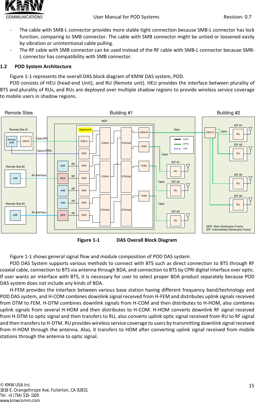
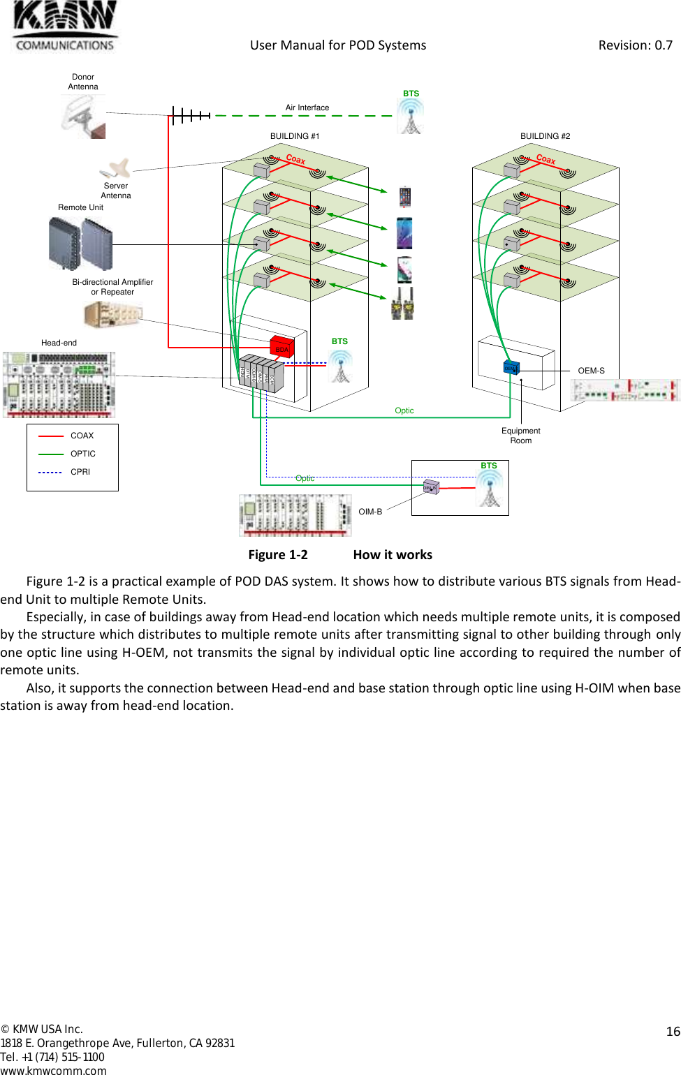
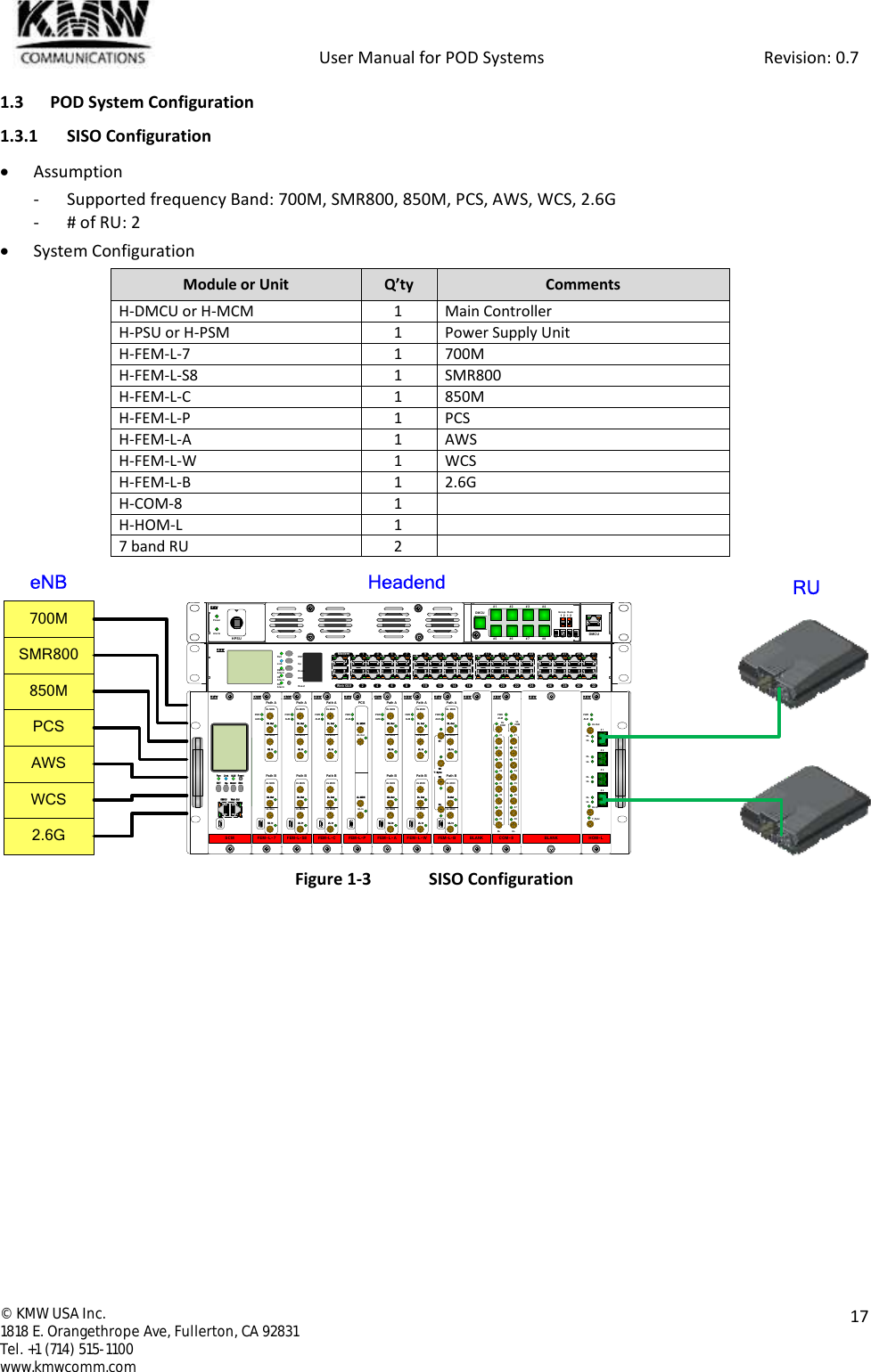
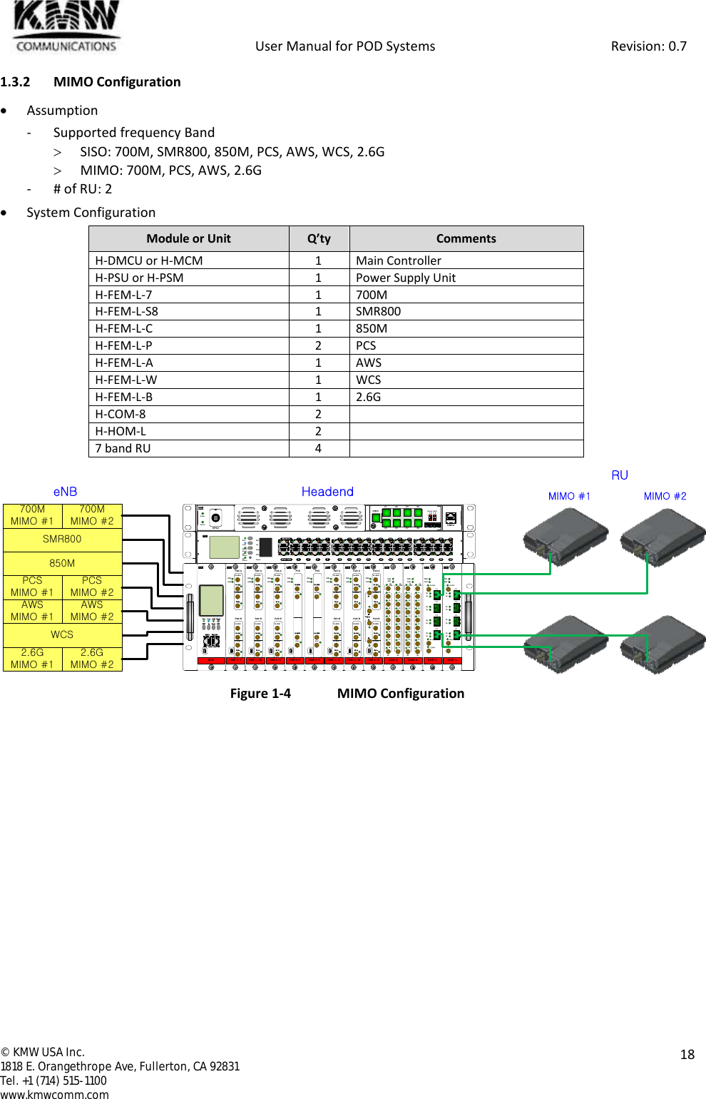
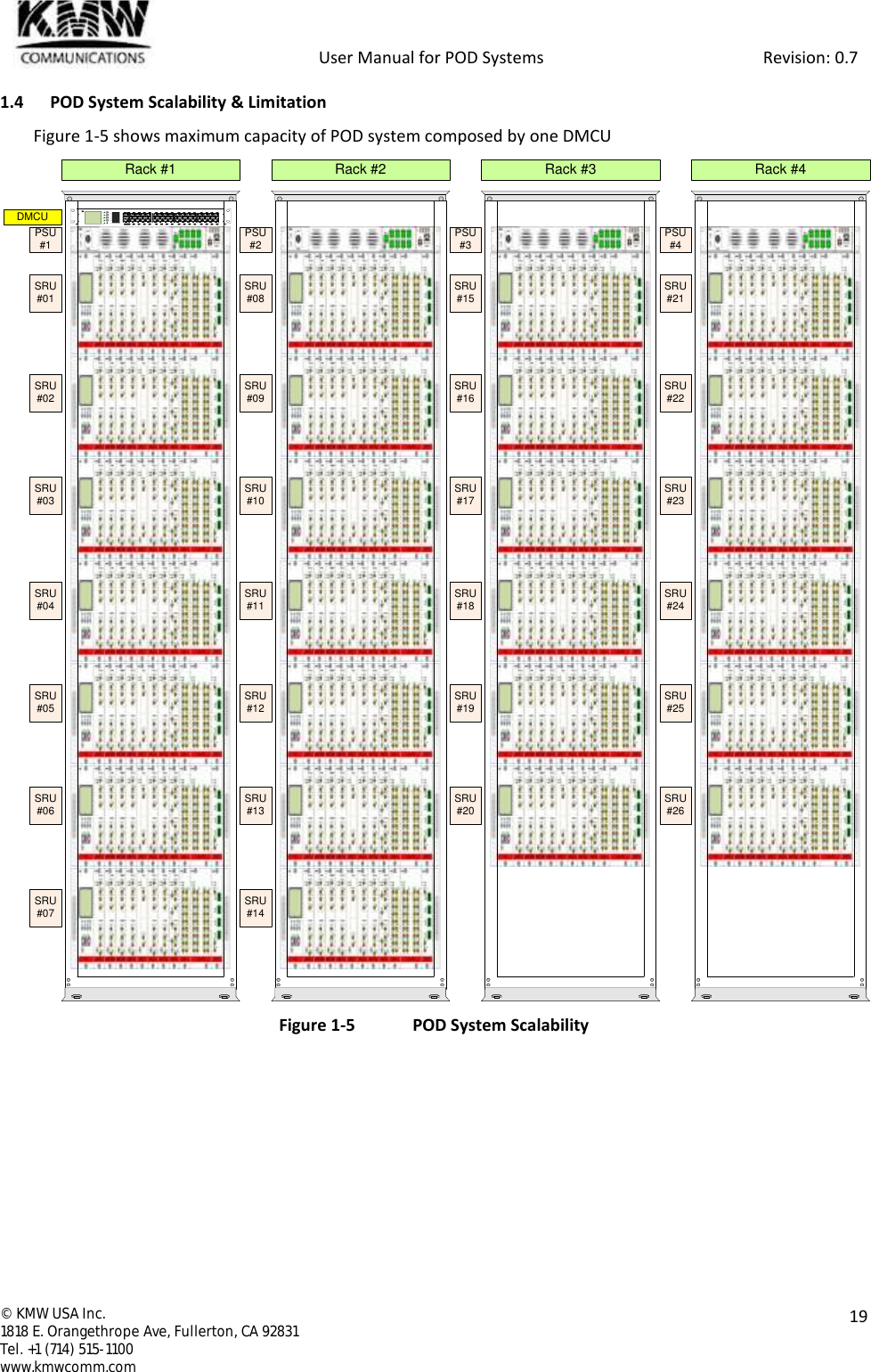
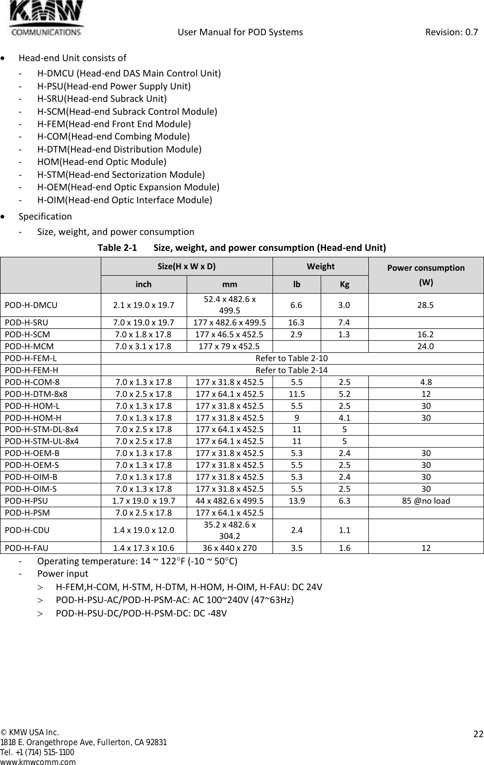
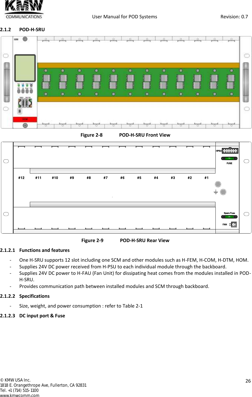
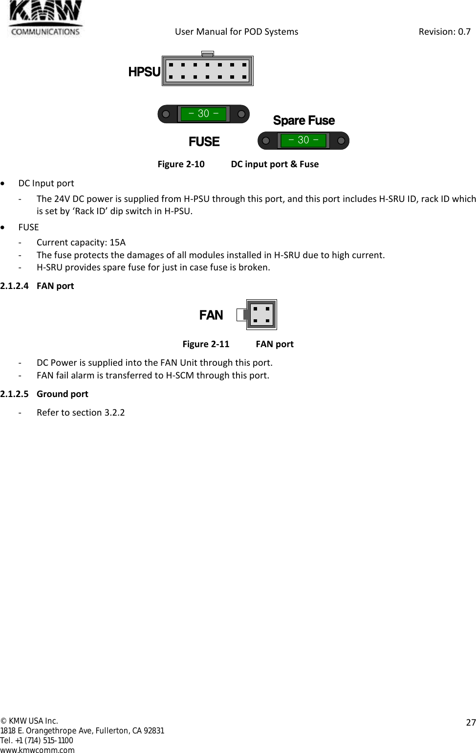
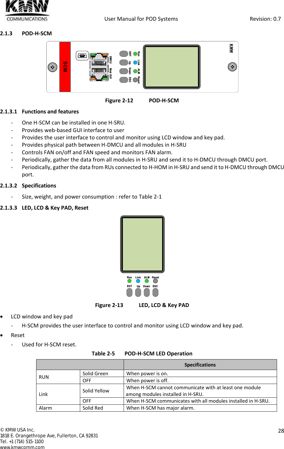
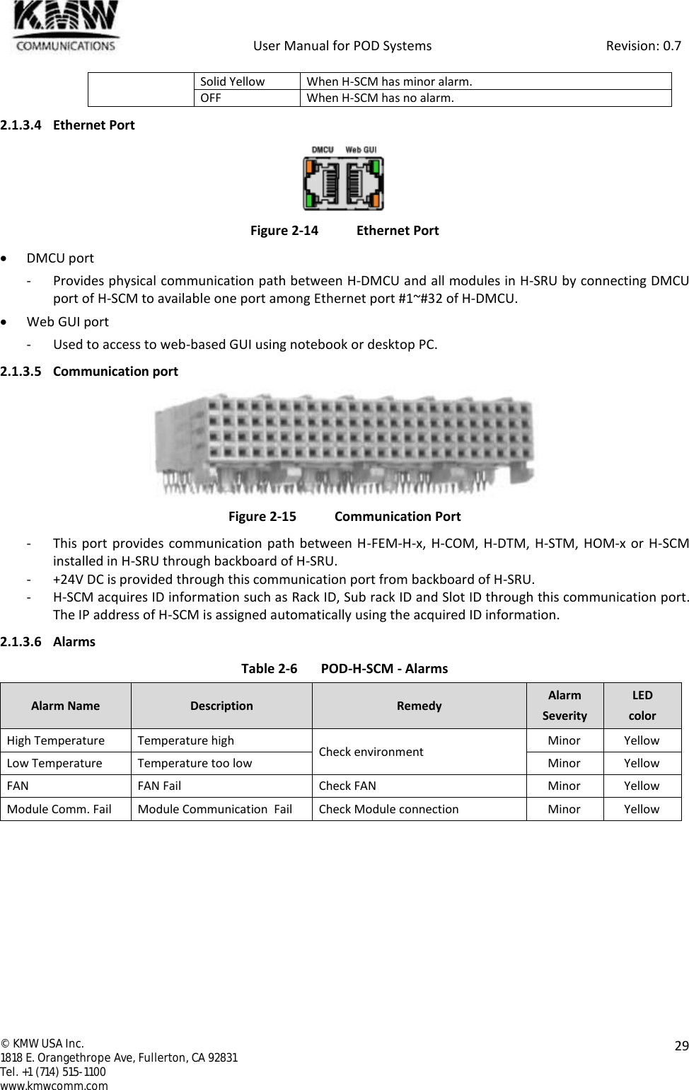
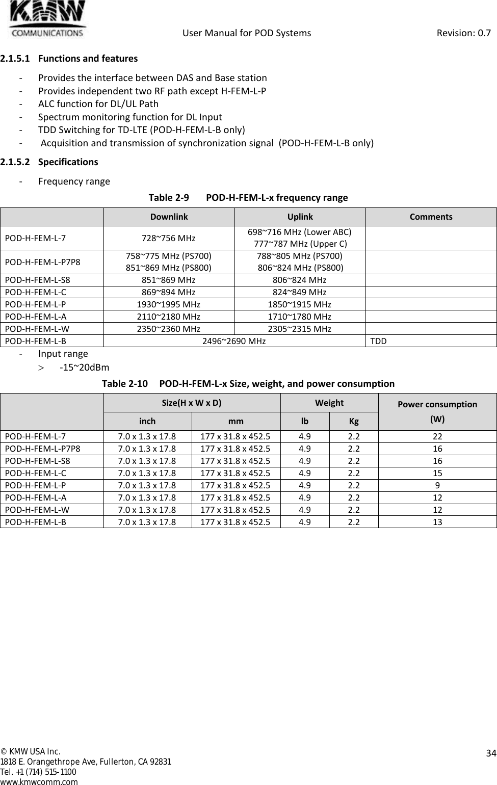
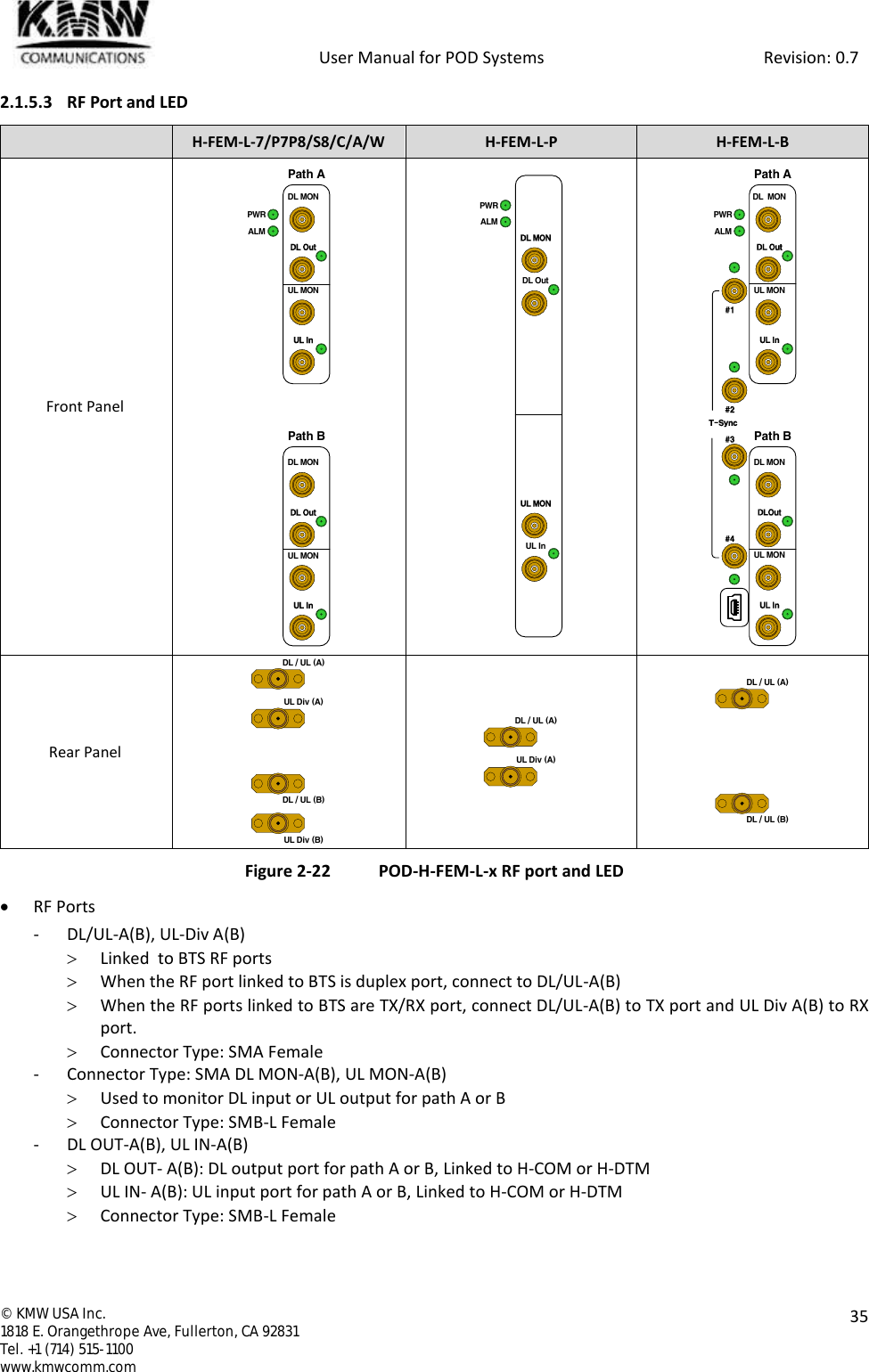
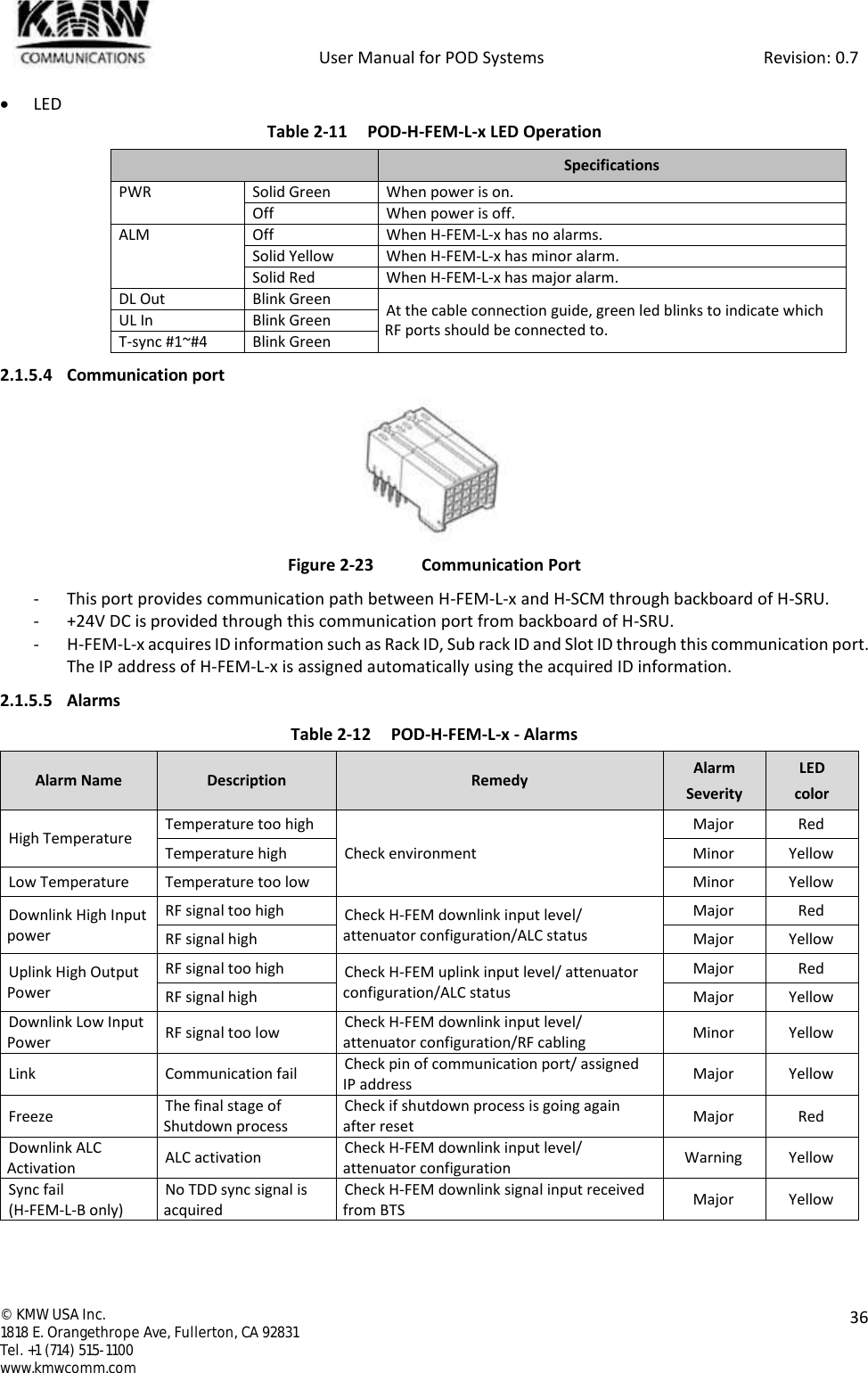
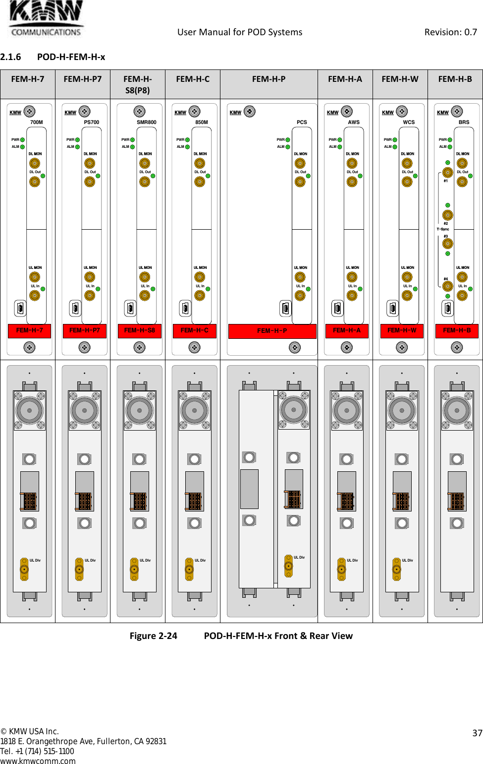
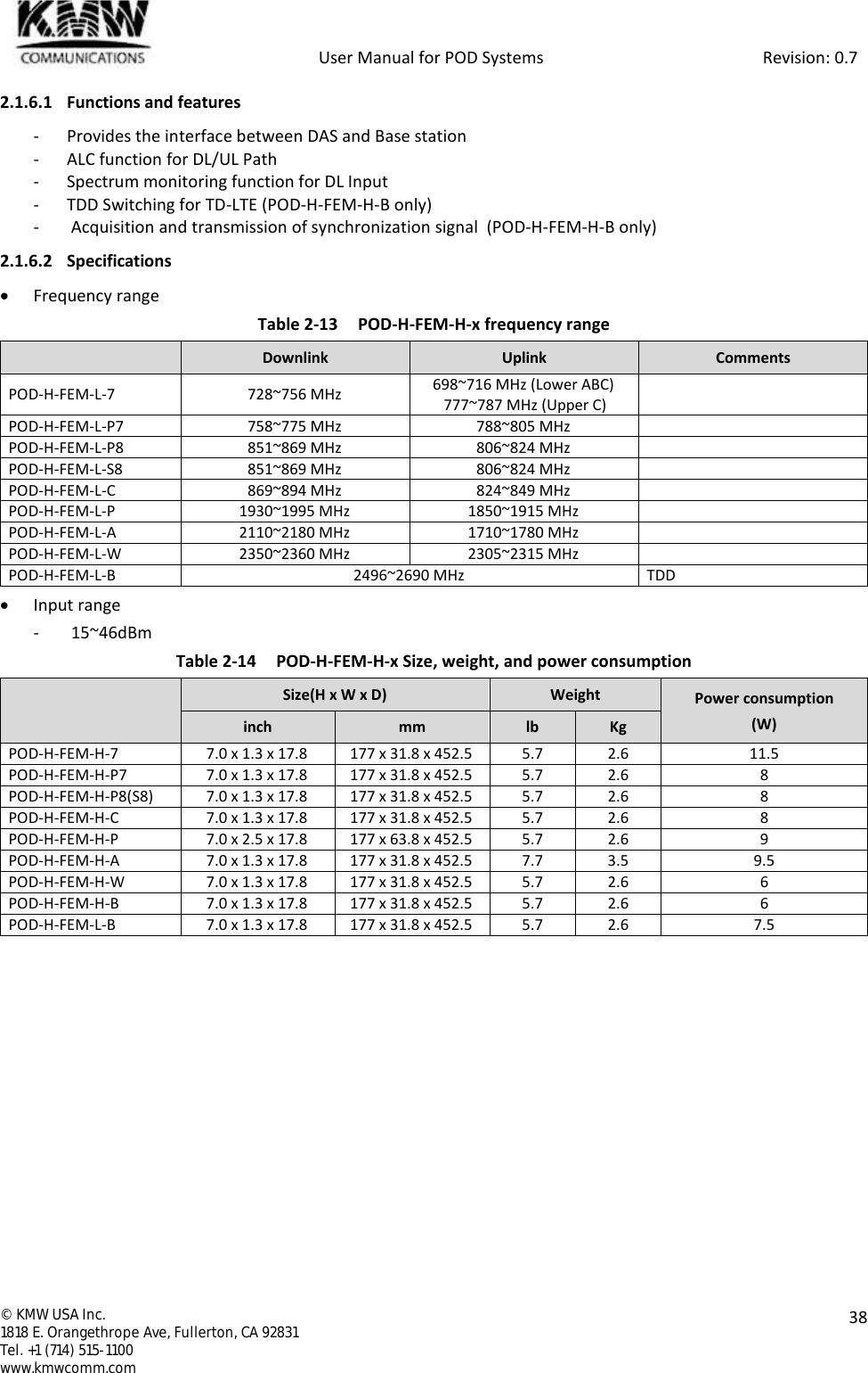
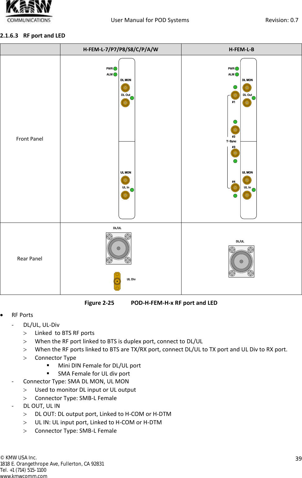
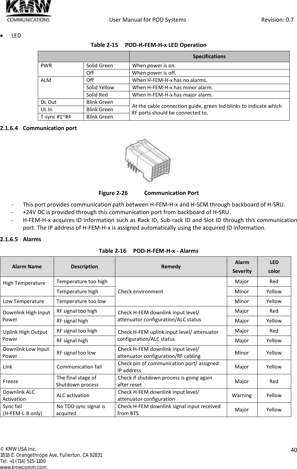
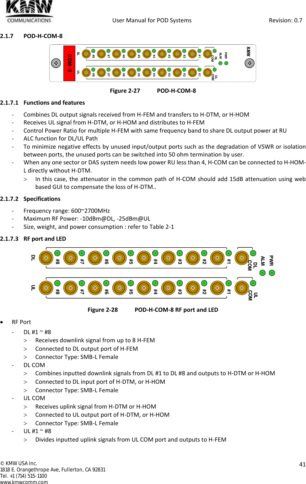
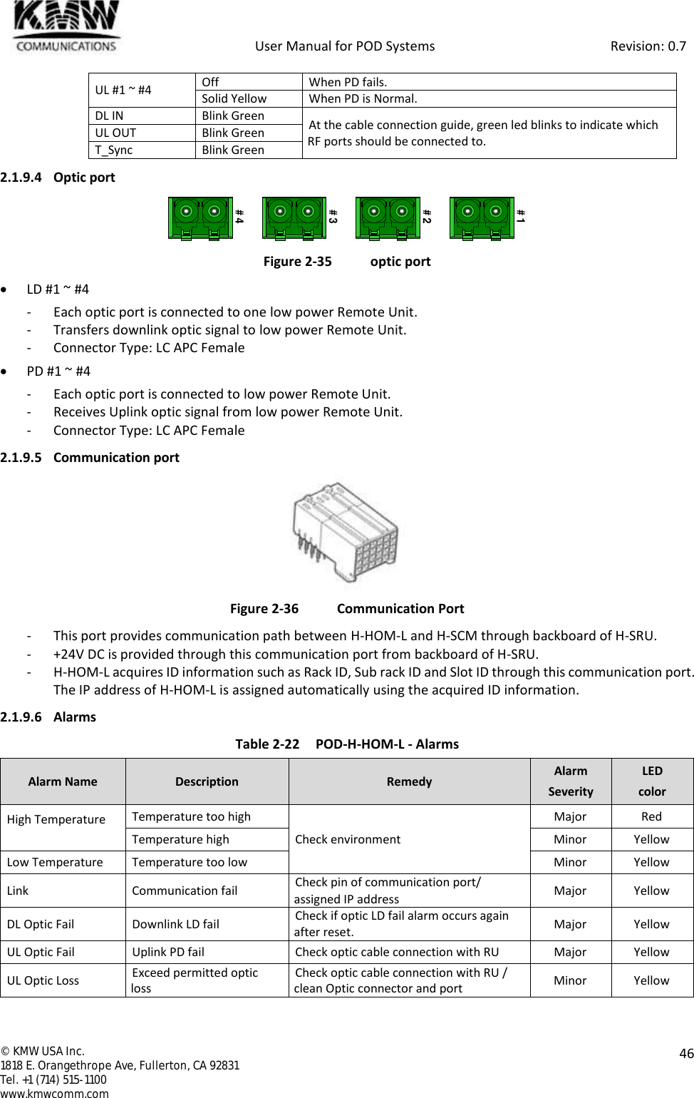
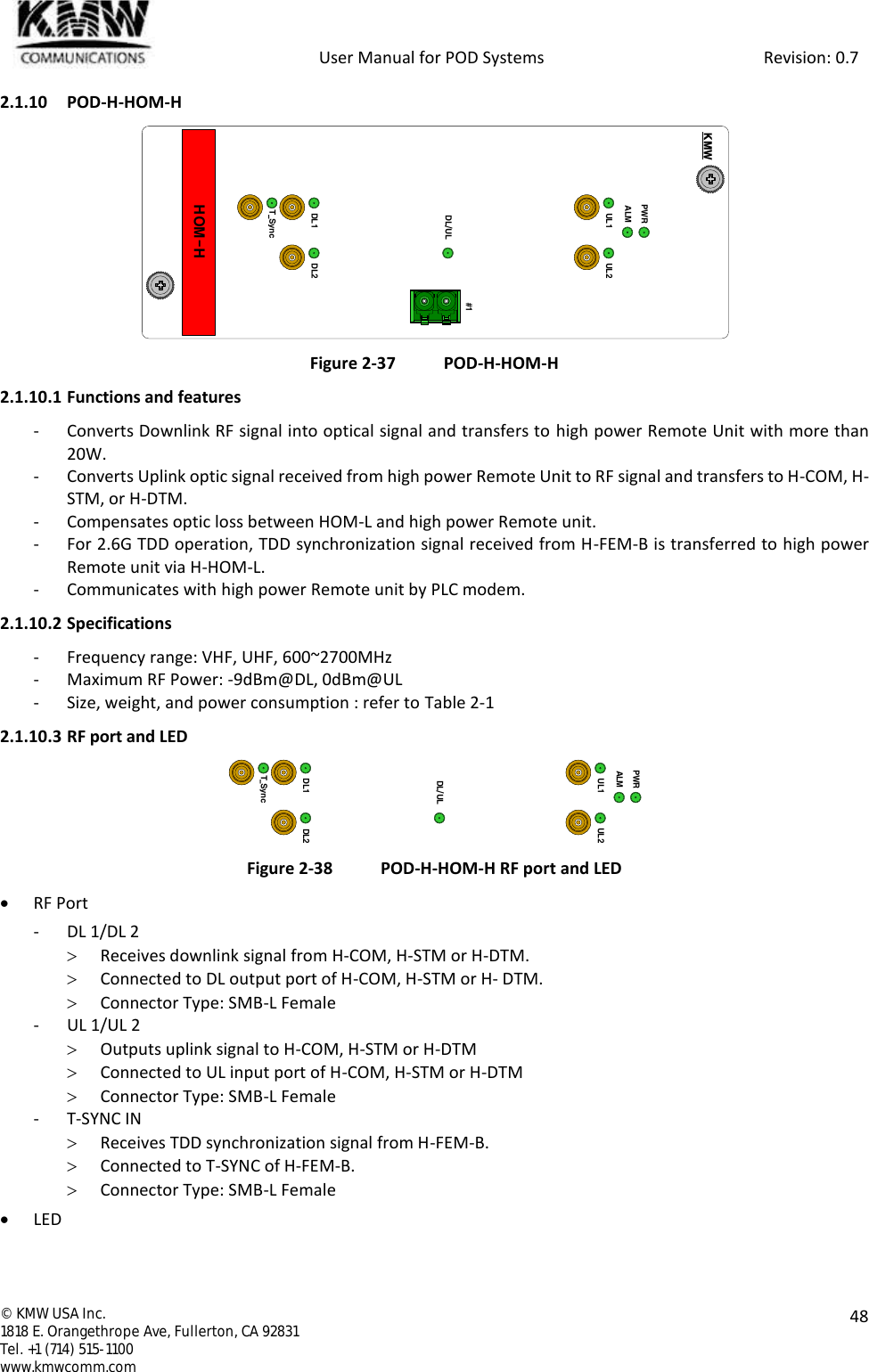
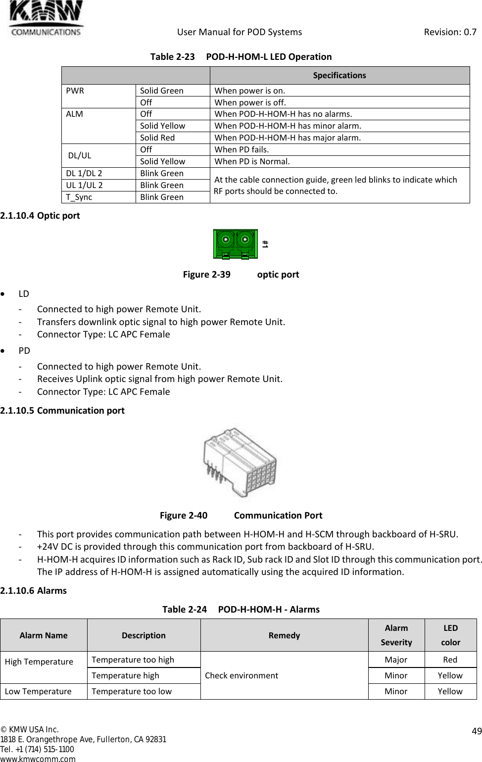
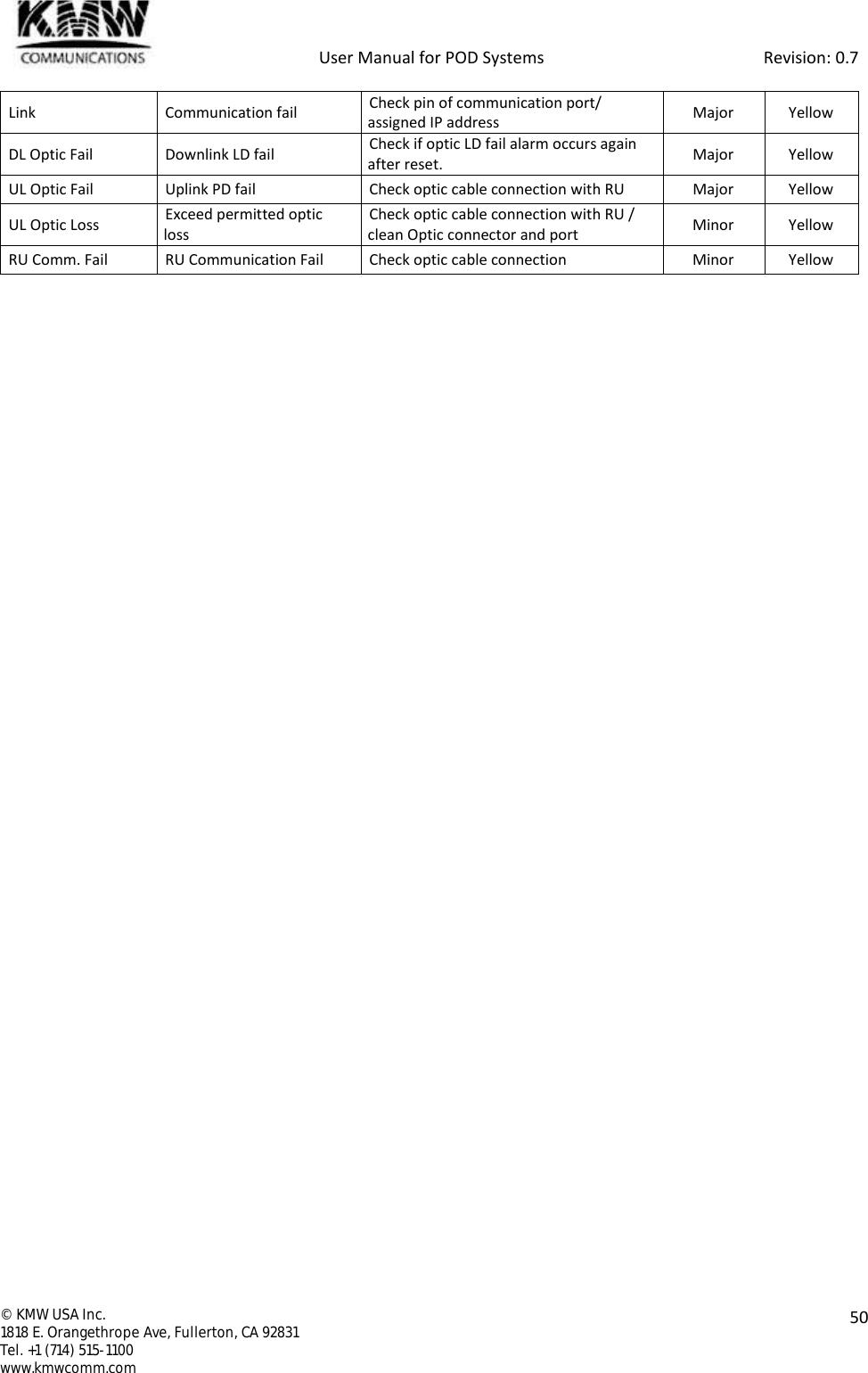
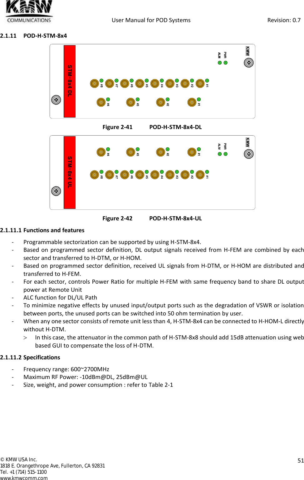
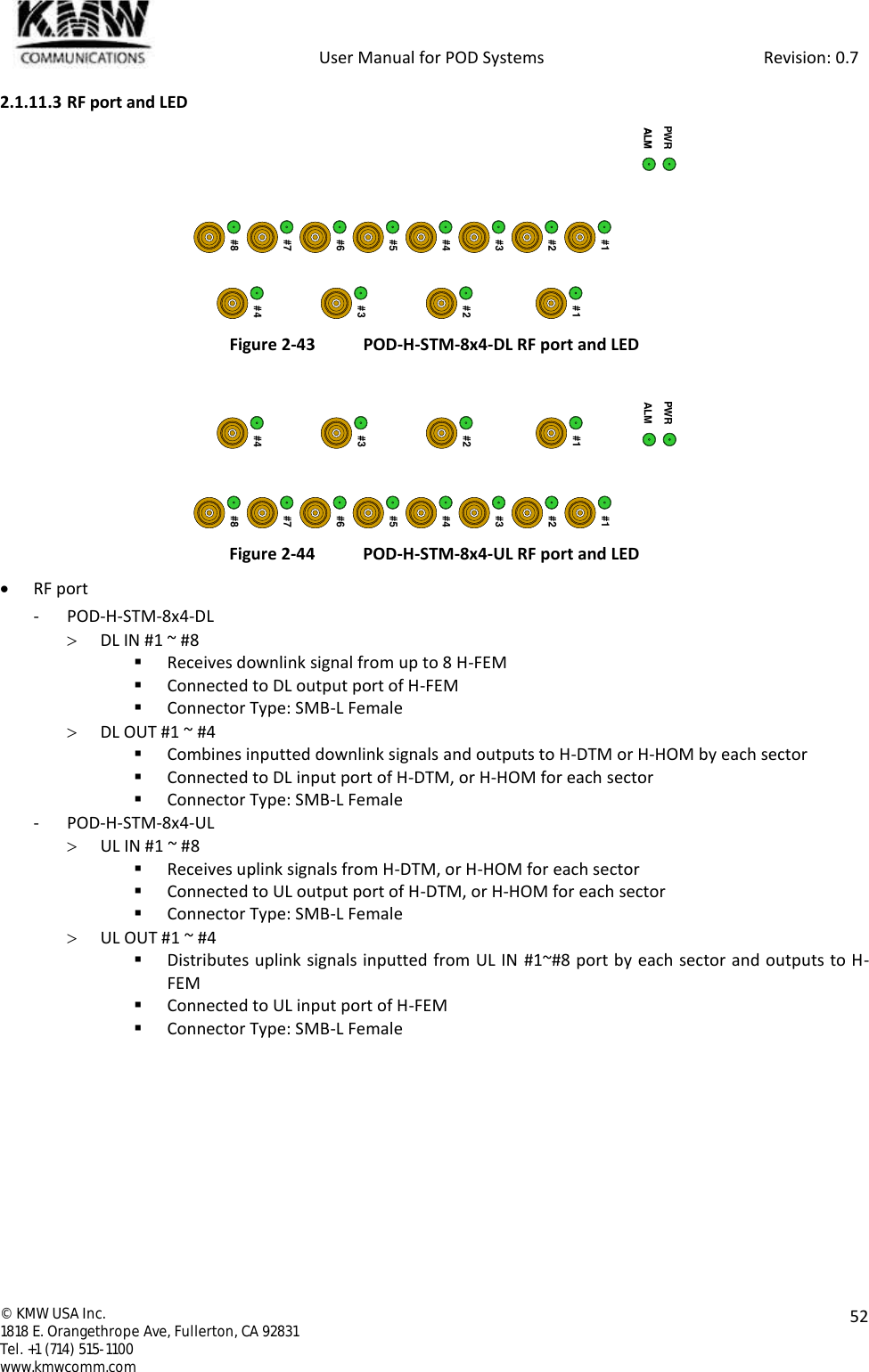
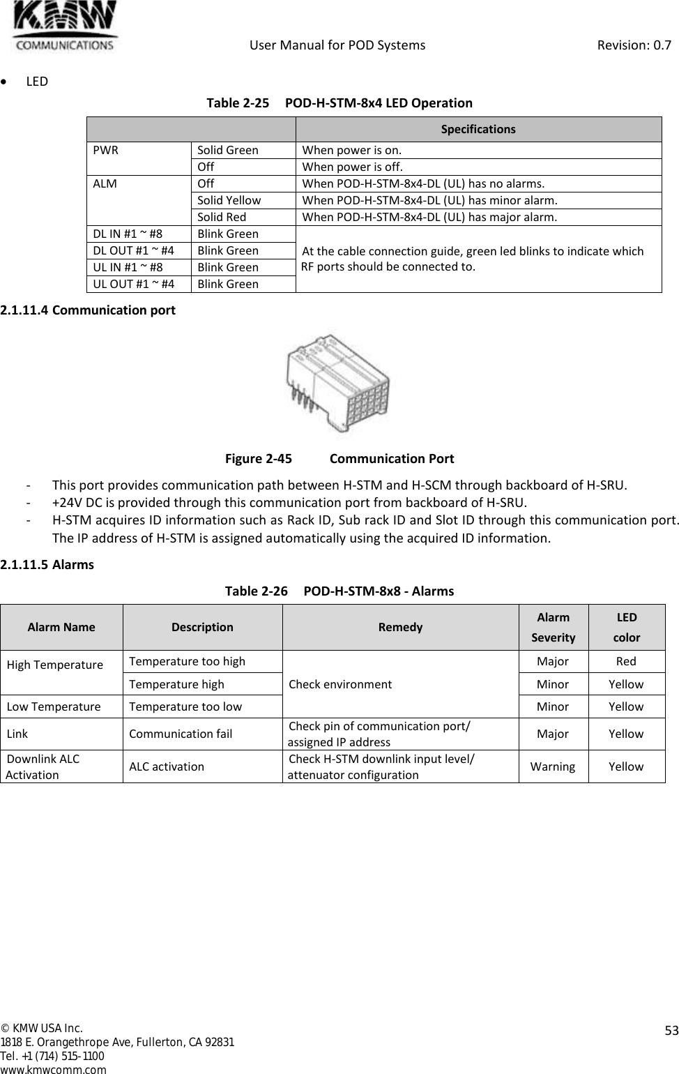
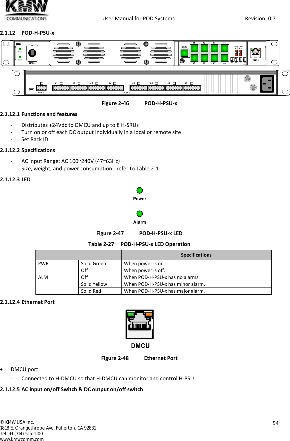
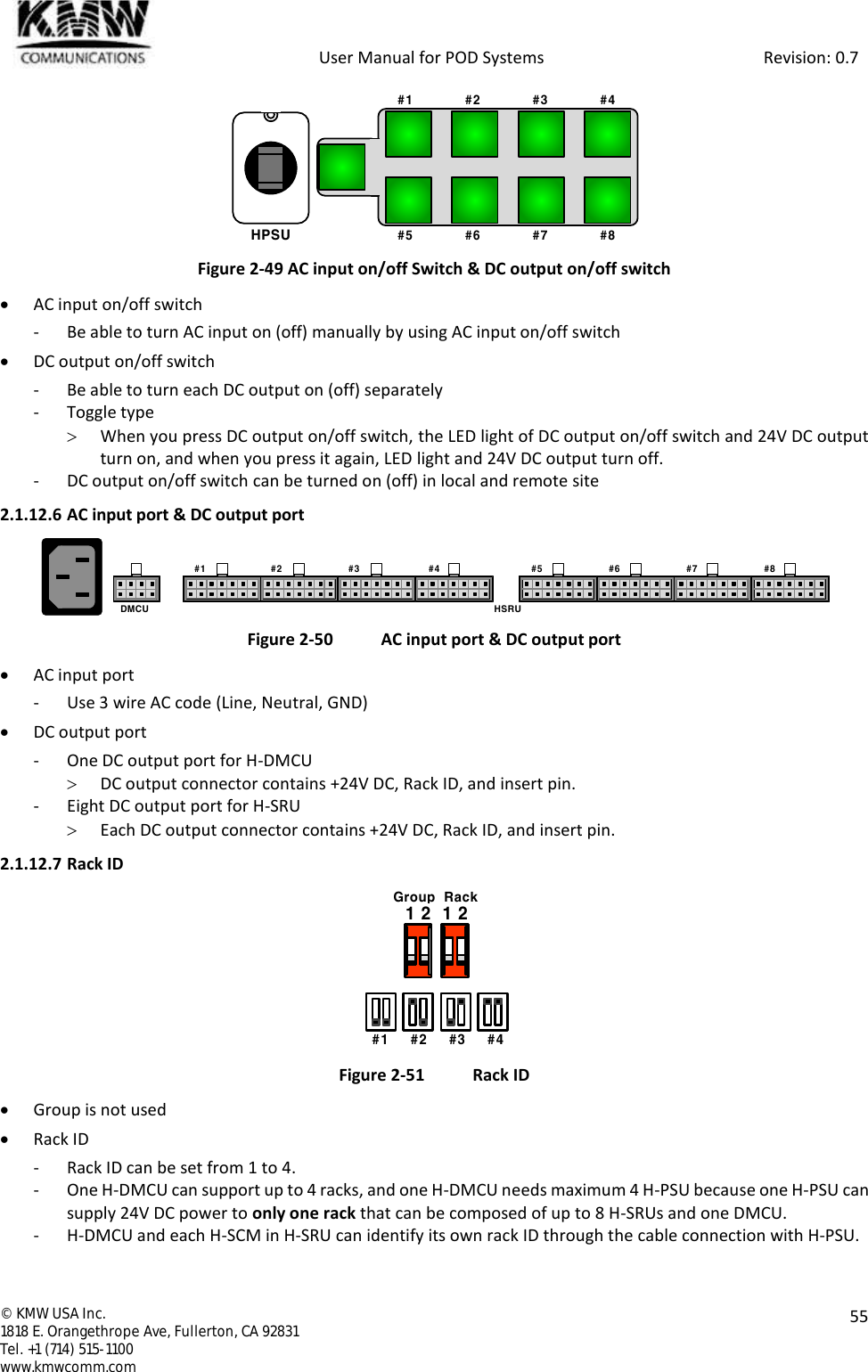
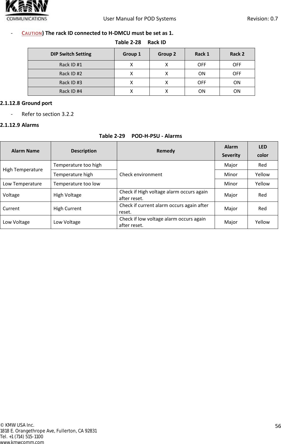
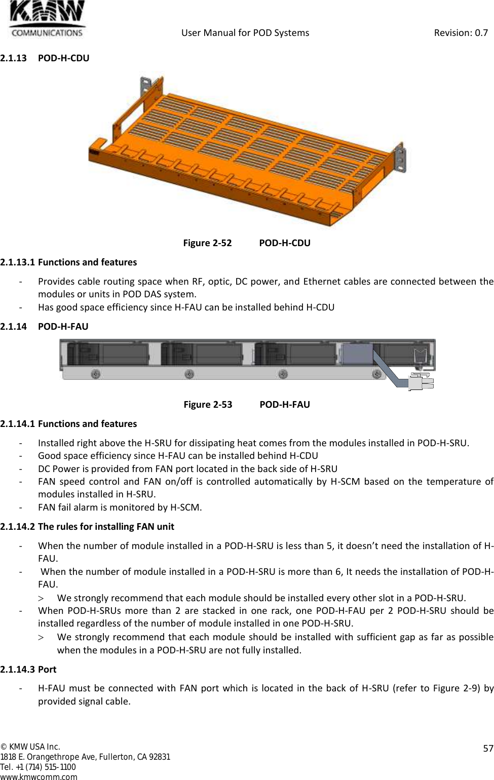
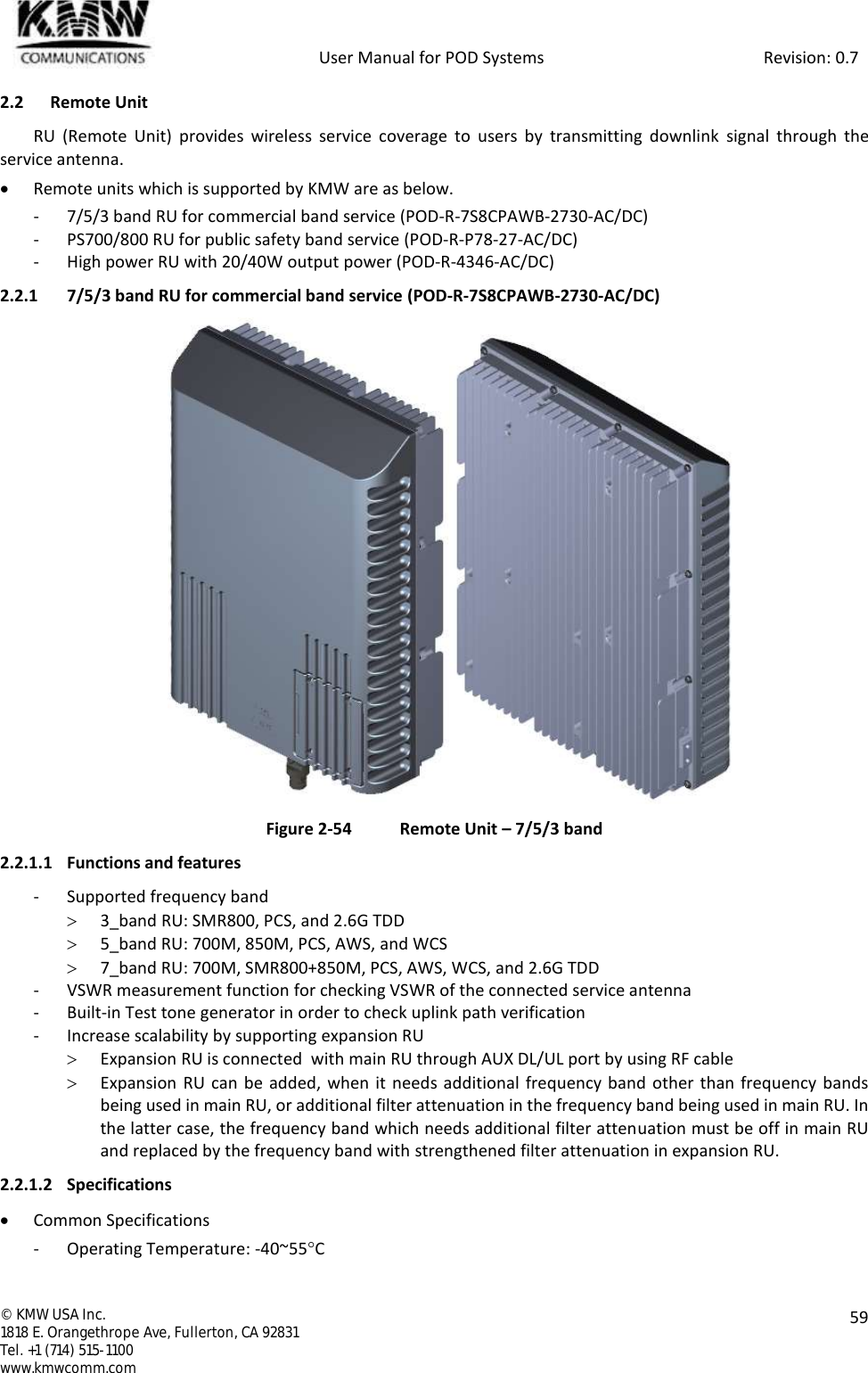
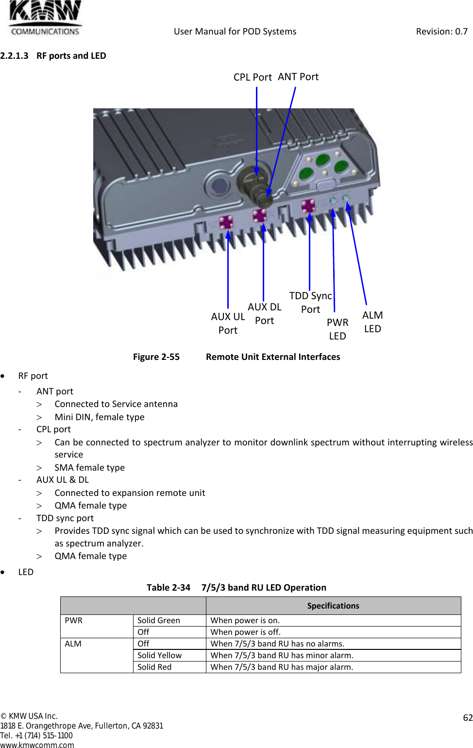
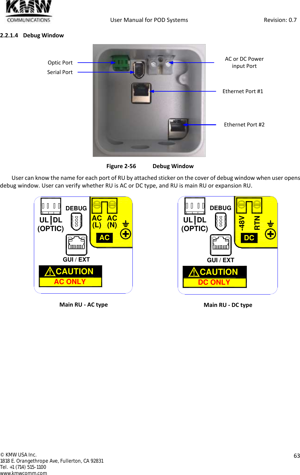
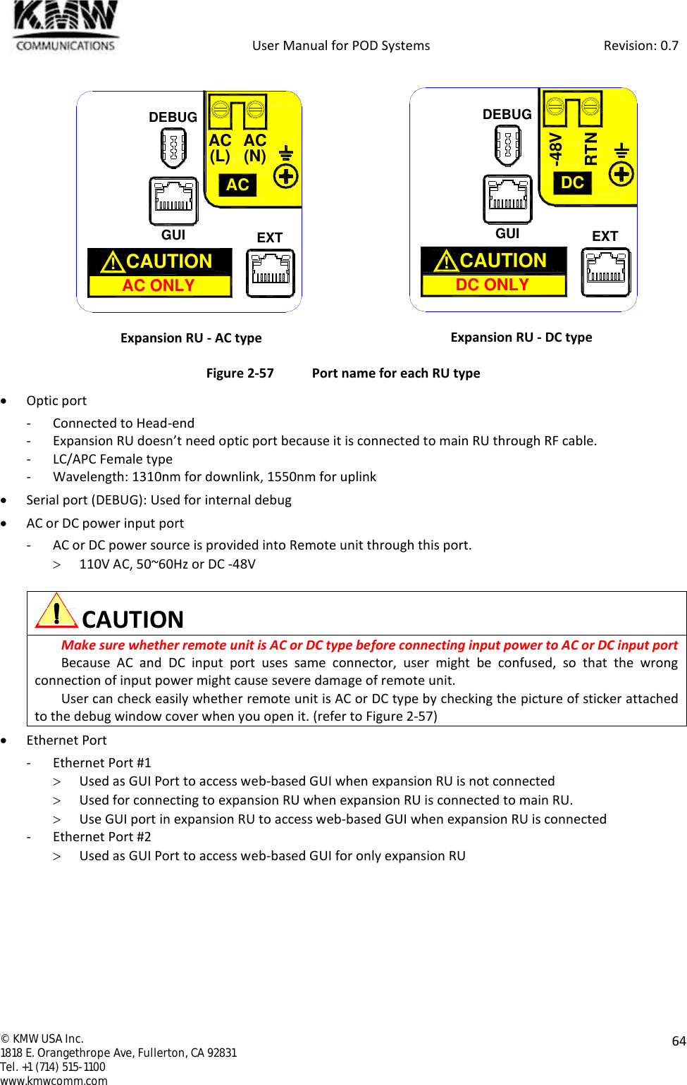
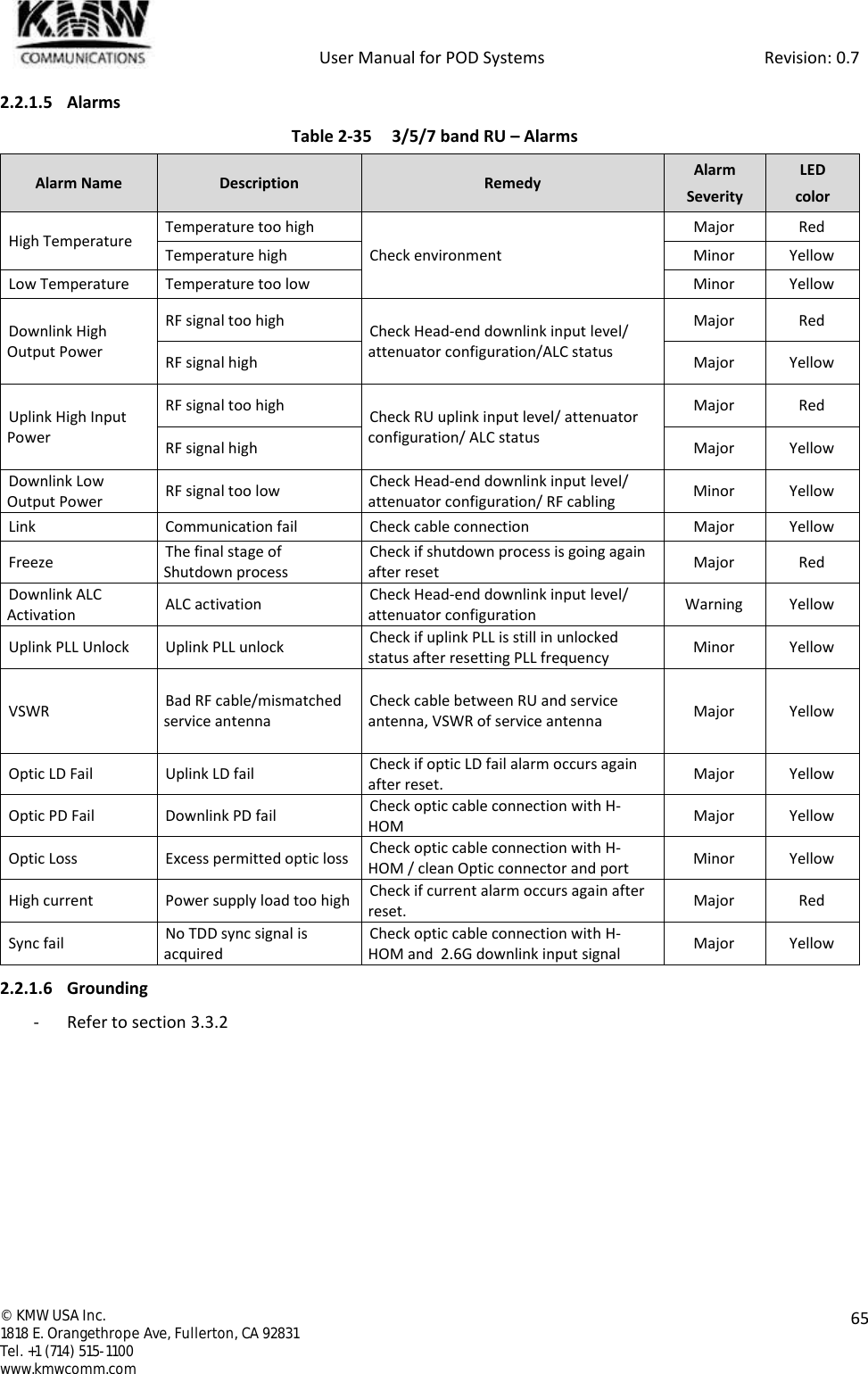
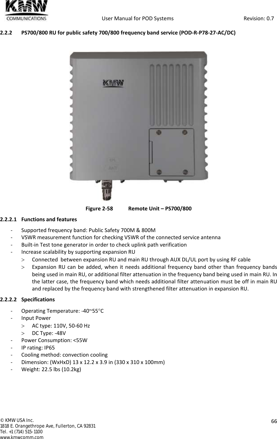
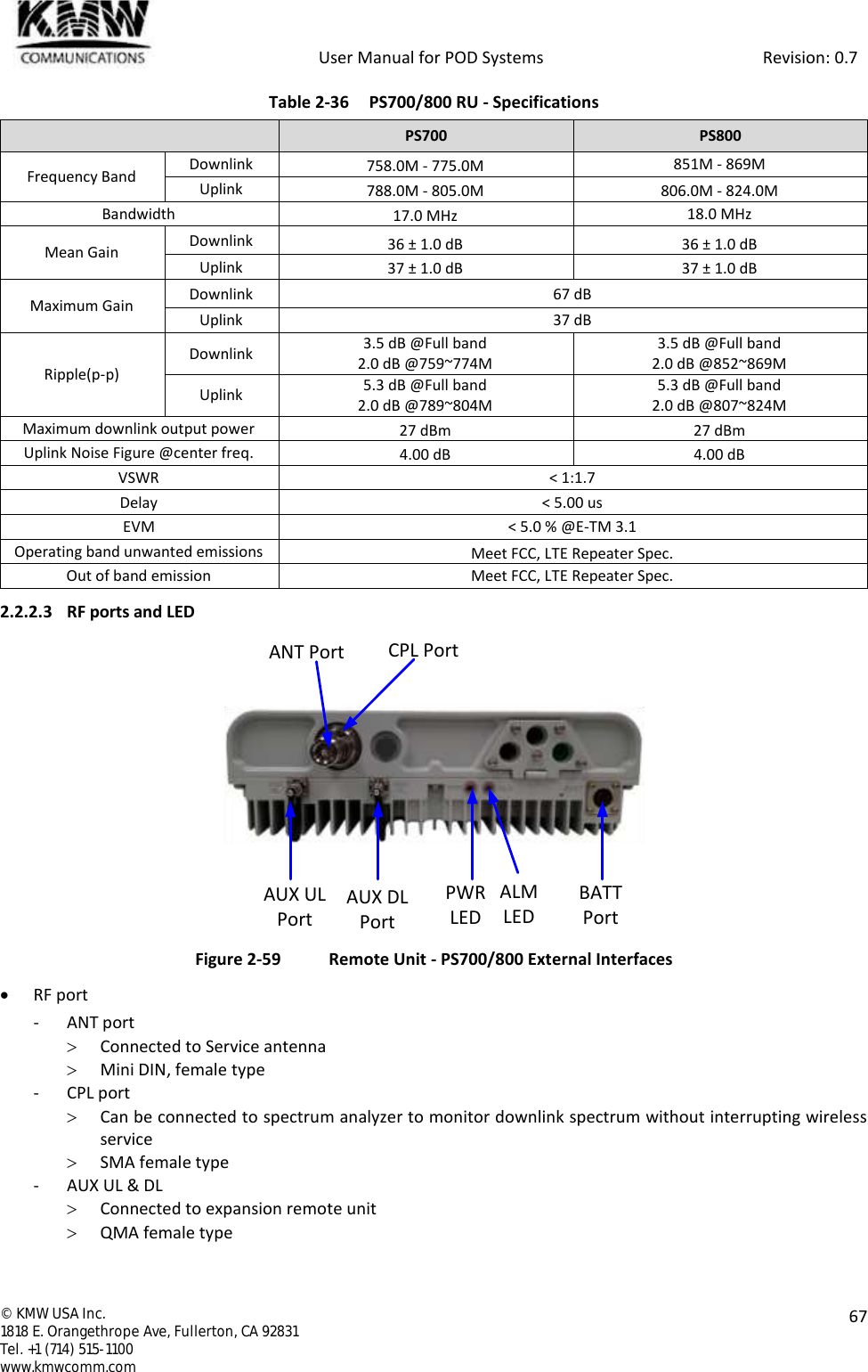
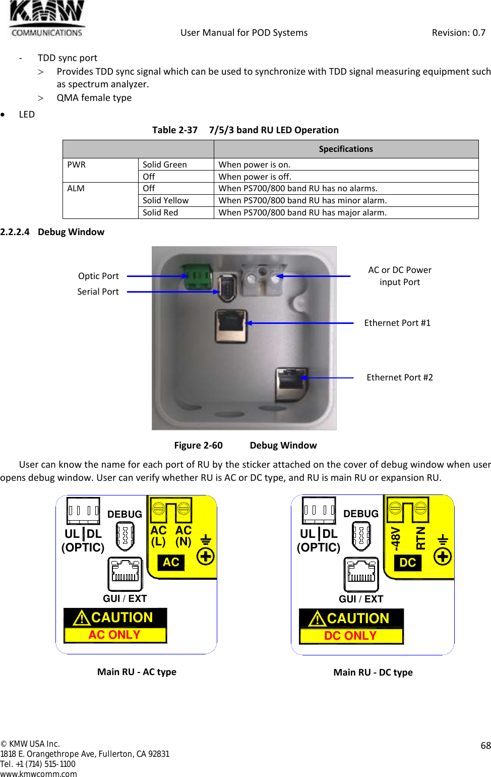
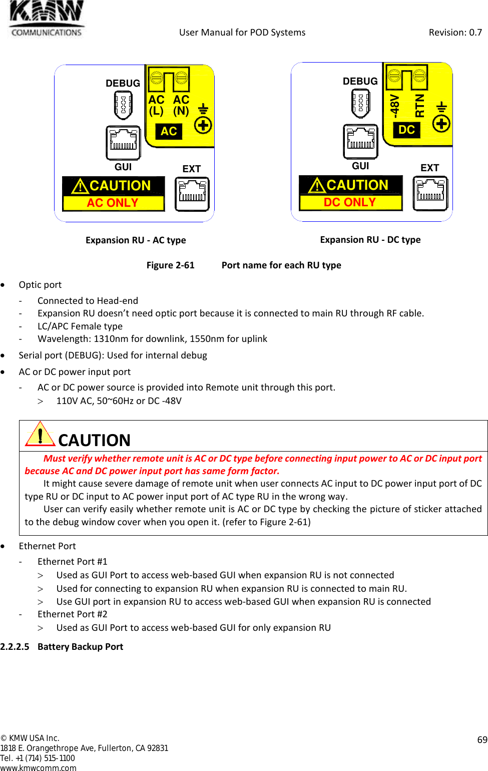
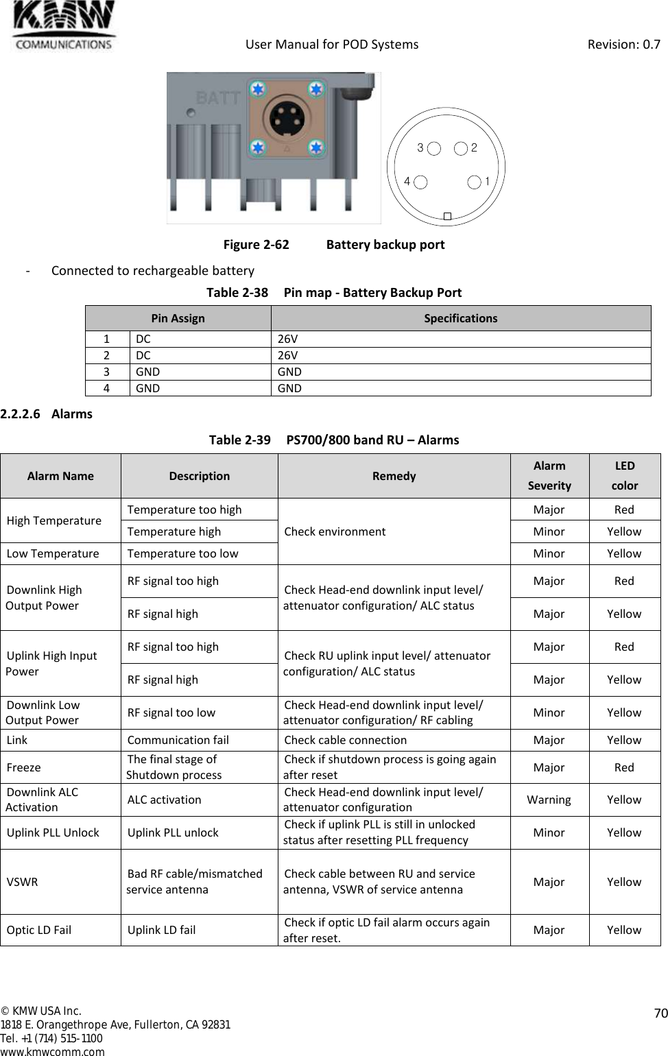
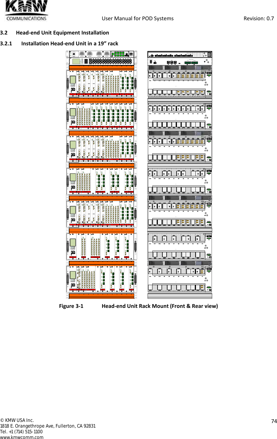
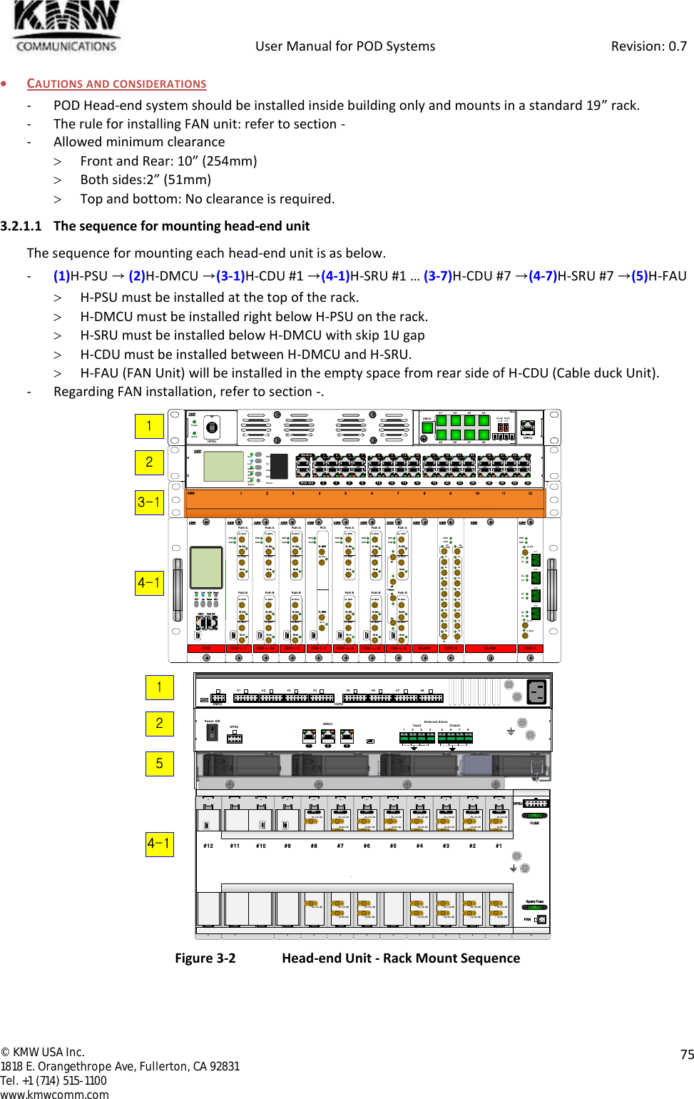
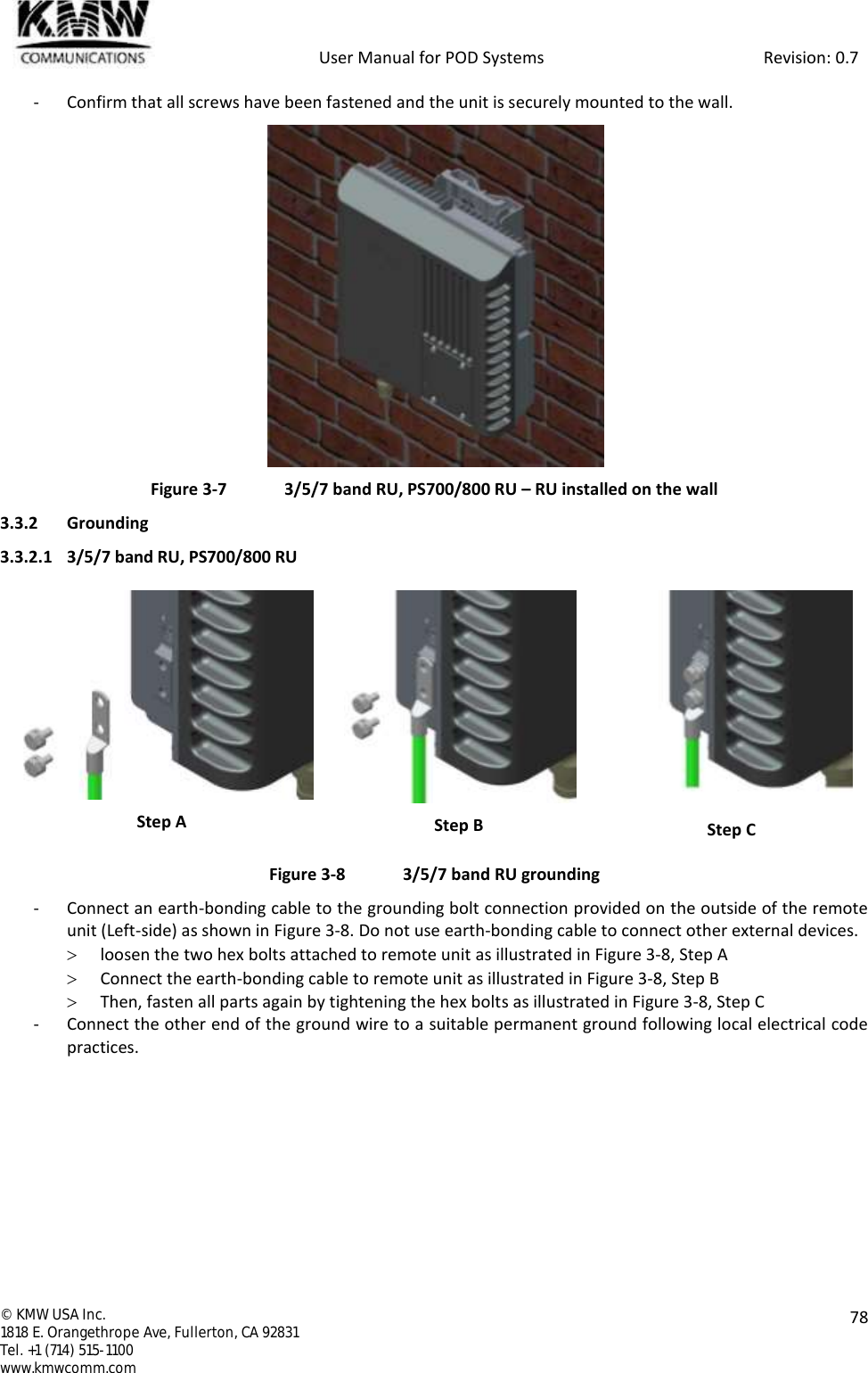
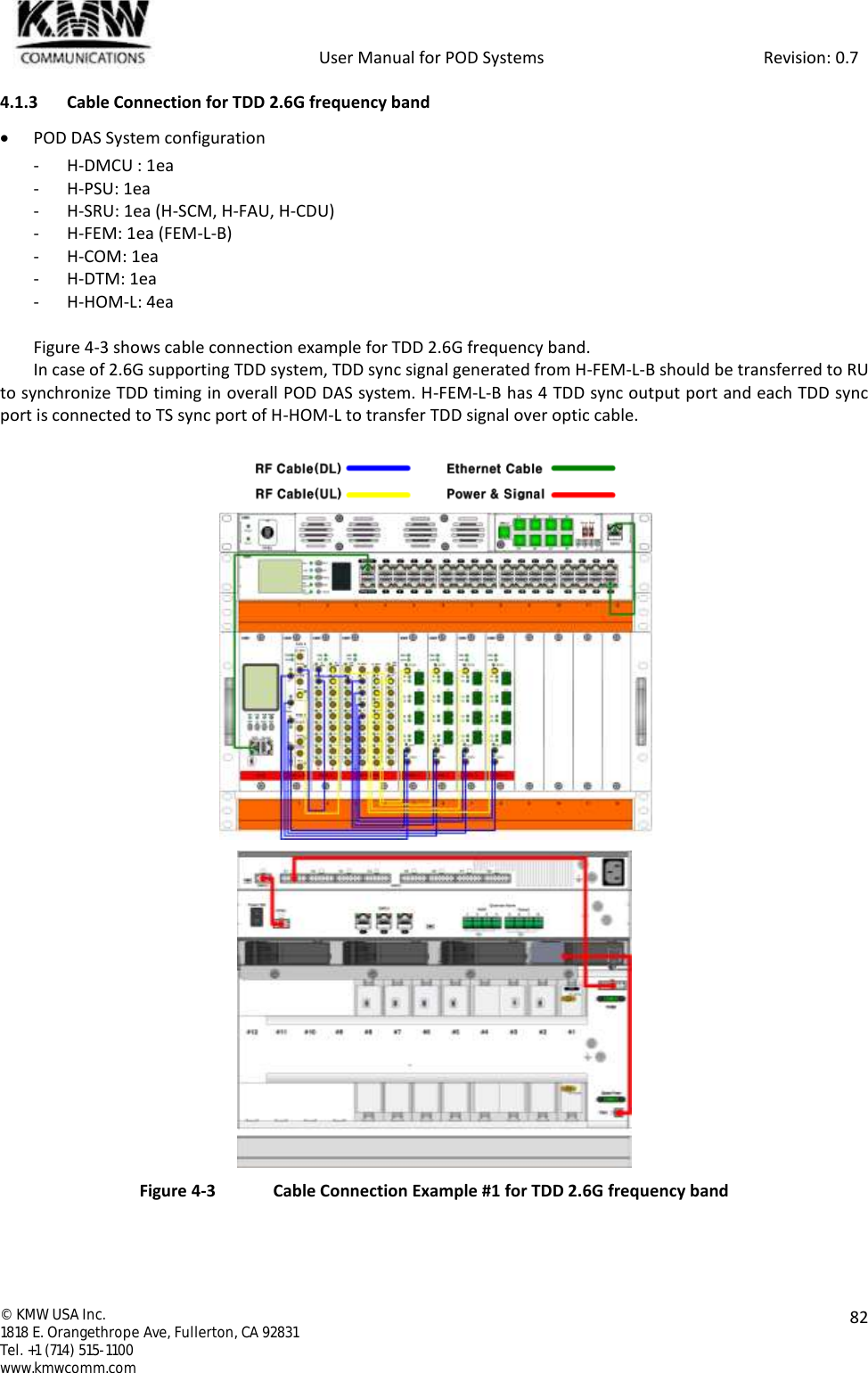
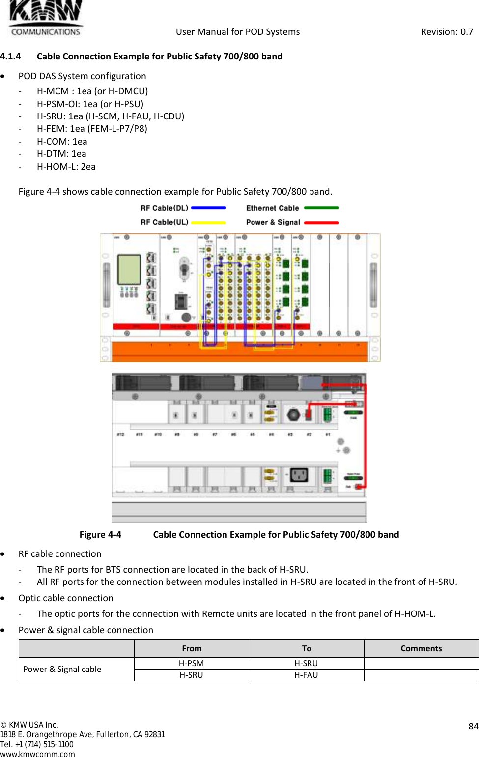
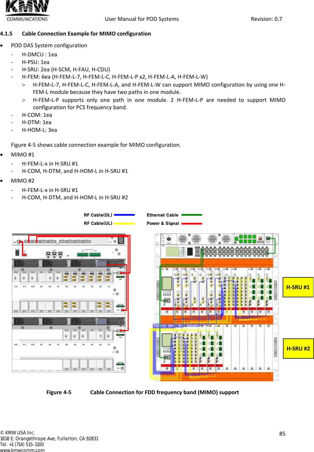
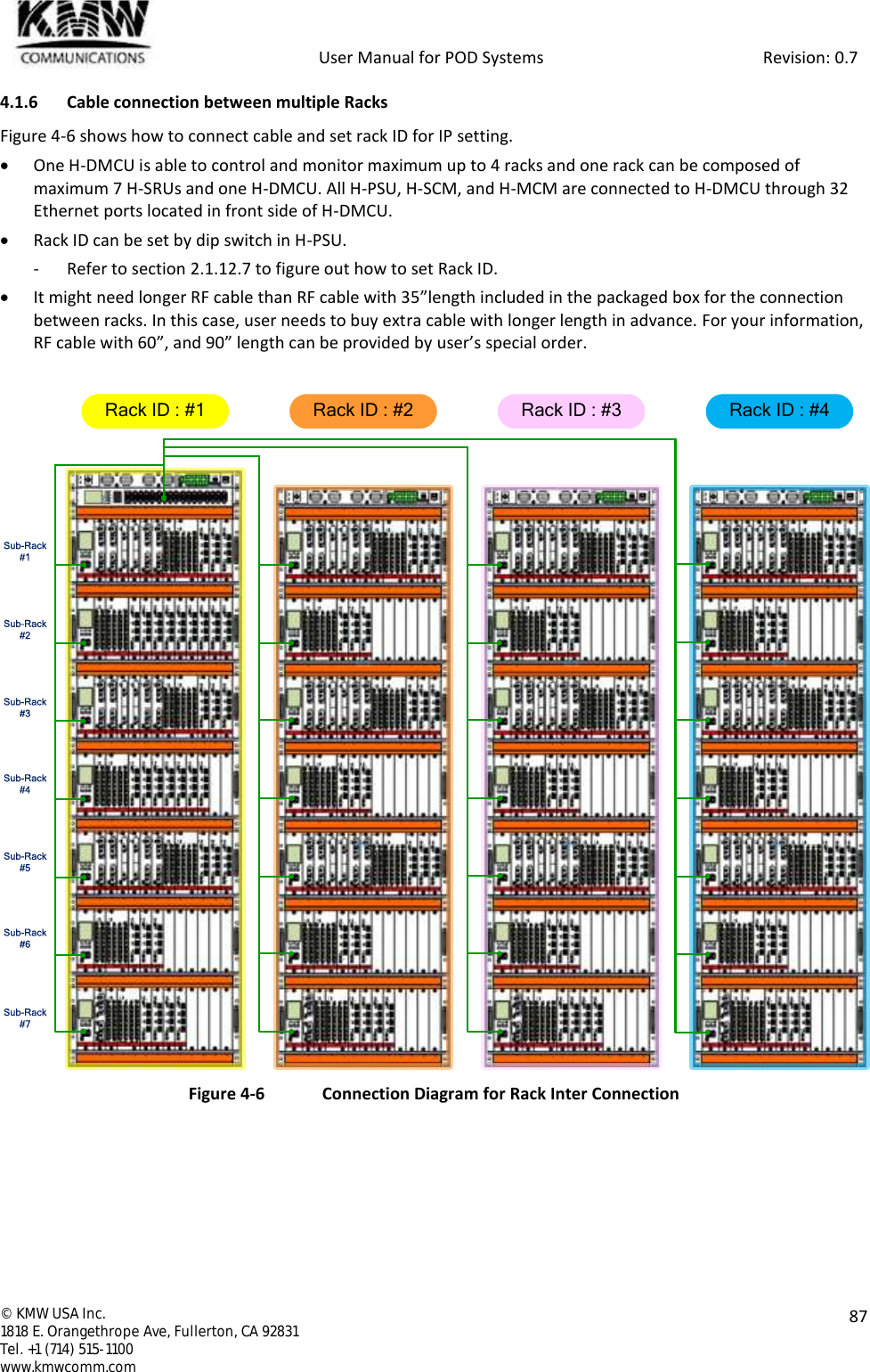
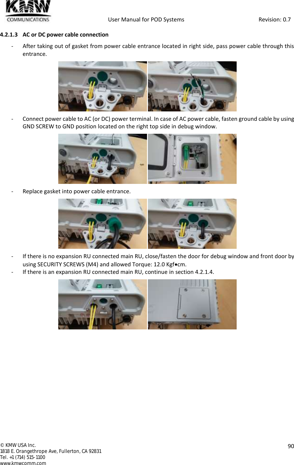
![User Manual for POD Systems Revision: 0.7 © KMW USA Inc. 1818 E. Orangethrope Ave, Fullerton, CA 92831 Tel. +1 (714) 515-1100 www.kmwcomm.com 21 2. POD SYSTEM COMPONENTS 2.1 Head-end Unit Figure 2-1 Head-end Unit Front View Figure 2-2 Head-end Unit Rear View H-SRUFEM-L-WUL MONDL MONDL OutUL InUL MONDL MONDL OutUL InPWRALMPath APath BKMWFEM-L-AUL MONDL MONDL OutUL InUL MONDL MONDL OutUL InPWRALMPath APath BKMWFEM-L-7UL MONDL MONDL OutUL InUL MonDL MONDL OutUL InPWRALMPath APath BKMWFEM-L-S8UL MONDL MONDL OutUL InUL MONDL MONDL OutUL InPWRALMPath APath BKMWFEM-L-P7/P8UL MONDL MONDL OutUL InUL MONDL MONDL OutUL InPWRALMPS700PS800KMWFEM-L-CUL MONDL MONDL OutUL InUL MONDL MONDL OutUL InPWRALMPath APath BKMWFEM-L-BUL MONDL MONDLOutUL InUL MONDL MONDL OutUL InPWRALMPath APath B#1#2#3#4T-SyncKMWFEM-L-PDL OutUL MONUL InDL MONPWRALMPCSKMWRun Link ALM ResetENT Up Down ESCDMCU Web GUISCMKMWCOM-8PWRALMDLCOM#1#2#3#4#5#6#7#8#1#2#3#4#5#6#7#8ULCOMDL ULKMWDTM-8x8PWRALMKMWVHFUHF#1#2#3#4#5#6#7#8#1#2#3#4#5#6#7#8DLMONDL ULVHFUHF#1#2#3#4#5#6#7#8#1#2#3#4#5#6#7#8ULMONIN OUT IN OUTHOM-LPWRALMUL OutDL InT_SyncDLULDLULDLULDLULKMW# 1# 2# 3# 4SCM [ FEM ] COM-8 DTM-8x8 HOM1 2 3 4 5 6 7 8 9 10 11 12KMWENTUpDownESCResetRunDMCUAlarmLinkHEAlarmRUAlarm12345 76 89 11 13 1510 12 14 1617 19 21 2318 20 22 2425 27 29 3126 28 30 32ModemWeb GUIKMWDMCUHPSUPowerAlarm#1 #2 #3 #4#5 #6 #7 #8DMCU #1 #2 #3 #41 2 1 2Group RackKMWDMCUH-PSUDMCUH-PSUH-SRUSCM[ FEM ]COM-8DTM-8x8HOMDL / UL (A)UL Div (A)DL / UL (B)UL Div (B)700M┌┌└└DL / UL (A)UL Div (A)DL / UL (B)UL Div (B)P7/P8┌┌└└DL / UL (A)UL Div (A)DL / UL (B)UL Div (B)S8┌┌└└DL / UL (A)UL Div (A)DL / UL (B)UL Div (B)850M┌┌└└DL / UL (A)UL Div (A)PCS┌┌DL / UL (A)UL Div (A)DL / UL (B)UL Div (B)AWS┌┌└└DL / UL (A)UL Div (A)DL / UL (B)UL Div (B)WCS┌┌└└DL / UL (A)DL / UL (B)BRS┌└- 30 -- 30 -#12 #11 #10 #9 #8 #7 #6 #5 #4 #3 #2 #1HPSUFUSESpare FuseFANHPSUPower SWDMCU1 2 3External AlarmInput Output1 2 3 4 5 6 7 8#1 #2 #3 #4 #5 #6 #7 #8 DMCU HSRU](https://usermanual.wiki/KMW/H-FEM-L-W/User-Guide-3129634-Page-21.png)