POD User Manual_v0.7


User Manual for POD Systems Revision: 0.7
© KMW USA Inc.
1818 E. Orangethrope Ave, Fullerton, CA 92831
Tel. +1 (714) 515-1100
www.kmwcomm.com
2
Revision History
Change List
Version
Change list
Contents
Version
Author
Descriptions
Date
0.1
KMW
Initial Release
5/14/2015
0.2
KMW
Update FCC Regulation Statement
12/23/2015
0.3
KMW
Update RF specification on 2.2 and 5
1/12/2016
0.4
KMW
Update FCC RF Exposure information
1/15/2016
0.5
KMW
Make typo correct
1/18/2016
0.6
KMW
Change the RF Radiation Exposure
2/4/2016
0.7
KMW
Update RF Exposure statement and HAAT information
2/24/2016

User Manual for POD Systems Revision: 0.7
© KMW USA Inc.
1818 E. Orangethrope Ave, Fullerton, CA 92831
Tel. +1 (714) 515-1100
www.kmwcomm.com
3
List for Acronyms
AGC Automatic Gain Control
ALC Automatic Level Control
BDA Bi-Directional Amplifier
BOM Bill of Material
BTS Base Transceiver Station
DAS Distributed Antenna System
DL Downlink
Downlink Path covered from the Base Transceiver Station (BTS) to the subscribers’ service area
via the repeater
HEU Head-end Unit
IF Intermediate Frequency
LNA Low Noise Amplifier
LTE Long Term Evolution
MS Mobile Station
NMS Network Management System
PA Power Amplifier
PSU Power Supply Unit
RF Radio Frequency
RU Remote Unit
UL Uplink
Uplink Path covered from the subscribers’ service area to the Base Transceiver Station (BTS)
via the repeater
Uptime Time during which a Unit or Module is in operation
VSWR Voltage Standing Wave Ratio

User Manual for POD Systems Revision: 0.7
© KMW USA Inc.
1818 E. Orangethrope Ave, Fullerton, CA 92831
Tel. +1 (714) 515-1100
www.kmwcomm.com
4
Table of Contents
1. POD System Overview ...................................................................................................................................... 14
1.1 Features of POD System ............................................................................................................................ 14
1.2 POD System Architecture .......................................................................................................................... 15
1.3 POD System Configuration ........................................................................................................................ 17
1.3.1 SISO Configuration .............................................................................................................................. 17
1.3.2 MIMO Configuration .......................................................................................................................... 18
1.4 POD System Scalability & Limitation .......................................................................................................... 19
2. POD system Components ................................................................................................................................. 21
2.1 Head-end Unit............................................................................................................................................ 21
2.1.1 POD-H-DMCU (DAS Main Control Unit) .............................................................................................. 23
2.1.1.1 Functions and features ............................................................................................................. 23
2.1.1.2 Specifications ............................................................................................................................ 23
2.1.1.3 LED, LCD & Key PAD, Reset ....................................................................................................... 23
2.1.1.4 Ethernet Ports ........................................................................................................................... 24
2.1.1.5 DC power input port & power switch ....................................................................................... 24
2.1.1.6 External Alarm Port .................................................................................................................. 24
2.1.1.7 Ground port .............................................................................................................................. 25
2.1.1.8 Alarms ....................................................................................................................................... 25
2.1.2 POD-H-SRU ......................................................................................................................................... 26
2.1.2.1 Functions and features ............................................................................................................. 26
2.1.2.2 Specifications ............................................................................................................................ 26
2.1.2.3 DC input port & Fuse ................................................................................................................ 26
2.1.2.4 FAN port .................................................................................................................................... 27
2.1.2.5 Ground port .............................................................................................................................. 27
2.1.3 POD-H-SCM ........................................................................................................................................ 28
2.1.3.1 Functions and features ............................................................................................................. 28
2.1.3.2 Specifications ............................................................................................................................ 28
2.1.3.3 LED, LCD & Key PAD, Reset ....................................................................................................... 28
2.1.3.4 Ethernet Port ............................................................................................................................ 29
2.1.3.5 Communication port ................................................................................................................. 29
2.1.3.6 Alarms ....................................................................................................................................... 29
2.1.4 POD-H-MCM ....................................................................................................................................... 30
2.1.4.1 Functions and features ............................................................................................................. 30
2.1.4.2 Specifications ............................................................................................................................ 30
2.1.4.3 LED, LCD & Key PAD, Reset ....................................................................................................... 30
2.1.4.4 Ethernet Ports ........................................................................................................................... 31

User Manual for POD Systems Revision: 0.7
© KMW USA Inc.
1818 E. Orangethrope Ave, Fullerton, CA 92831
Tel. +1 (714) 515-1100
www.kmwcomm.com
5
2.1.4.5 External Alarm Ports ................................................................................................................. 32
2.1.4.6 Communication port ................................................................................................................. 32
2.1.4.7 Alarms ....................................................................................................................................... 32
2.1.5 POD-H-FEM-L-x ................................................................................................................................... 33
2.1.5.1 Functions and features ............................................................................................................. 34
2.1.5.2 Specifications ............................................................................................................................ 34
2.1.5.3 RF Port and LED ........................................................................................................................ 35
2.1.5.4 Communication port ................................................................................................................. 36
2.1.5.5 Alarms ....................................................................................................................................... 36
2.1.6 POD-H-FEM-H-x .................................................................................................................................. 37
2.1.6.1 Functions and features ............................................................................................................. 38
2.1.6.2 Specifications ............................................................................................................................ 38
2.1.6.3 RF port and LED ........................................................................................................................ 39
2.1.6.4 Communication port ................................................................................................................. 40
2.1.6.5 Alarms ....................................................................................................................................... 40
2.1.7 POD-H-COM-8 .................................................................................................................................... 41
2.1.7.1 Functions and features ............................................................................................................. 41
2.1.7.2 Specifications ............................................................................................................................ 41
2.1.7.3 RF port and LED ........................................................................................................................ 41
2.1.7.4 Communication port ................................................................................................................. 42
2.1.7.5 Alarms ....................................................................................................................................... 42
2.1.8 POD-H-DTM-8x8 ................................................................................................................................. 43
2.1.8.1 Functions and features ............................................................................................................. 43
2.1.8.2 Specifications ............................................................................................................................ 43
2.1.8.3 RF port and LED ........................................................................................................................ 43
2.1.8.4 Communication port ................................................................................................................. 44
2.1.8.5 Alarms ....................................................................................................................................... 44
2.1.9 POD-H-HOM-L .................................................................................................................................... 45
2.1.9.1 Functions and features ............................................................................................................. 45
2.1.9.2 Specifications ............................................................................................................................ 45
2.1.9.3 RF port and LED ........................................................................................................................ 45
2.1.9.4 Optic port .................................................................................................................................. 46
2.1.9.5 Communication port ................................................................................................................. 46
2.1.9.6 Alarms ....................................................................................................................................... 46
2.1.10 POD-H-HOM-H .................................................................................................................................... 48
2.1.10.1 Functions and features ............................................................................................................ 48
2.1.10.2 Specifications .......................................................................................................................... 48

User Manual for POD Systems Revision: 0.7
© KMW USA Inc.
1818 E. Orangethrope Ave, Fullerton, CA 92831
Tel. +1 (714) 515-1100
www.kmwcomm.com
6
2.1.10.3 RF port and LED ....................................................................................................................... 48
2.1.10.4 Optic port ................................................................................................................................ 49
2.1.10.5 Communication port ............................................................................................................... 49
2.1.10.6 Alarms ..................................................................................................................................... 49
2.1.11 POD-H-STM-8x4 .................................................................................................................................. 51
2.1.11.1 Functions and features ............................................................................................................ 51
2.1.11.2 Specifications .......................................................................................................................... 51
2.1.11.3 RF port and LED ....................................................................................................................... 52
2.1.11.4 Communication port ............................................................................................................... 53
2.1.11.5 Alarms ..................................................................................................................................... 53
2.1.12 POD-H-PSU-x ...................................................................................................................................... 54
2.1.12.1 Functions and features ............................................................................................................ 54
2.1.12.2 Specifications .......................................................................................................................... 54
2.1.12.3 LED .......................................................................................................................................... 54
2.1.12.4 Ethernet Port ........................................................................................................................... 54
2.1.12.5 AC input on/off Switch & DC output on/off switch ................................................................. 54
2.1.12.6 AC input port & DC output port .............................................................................................. 55
2.1.12.7 Rack ID ..................................................................................................................................... 55
2.1.12.8 Ground port ............................................................................................................................ 56
2.1.12.9 Alarms ..................................................................................................................................... 56
2.1.13 POD-H-CDU ......................................................................................................................................... 57
2.1.13.1 Functions and features ............................................................................................................ 57
2.1.14 POD-H-FAU ......................................................................................................................................... 57
2.1.14.1 Functions and features ............................................................................................................ 57
2.1.14.2 The rules for installing FAN unit .............................................................................................. 57
2.1.14.3 Port .......................................................................................................................................... 57
2.1.14.4 Alarms ..................................................................................................................................... 58
2.2 Remote Unit ............................................................................................................................................... 59
2.2.1 7/5/3 band RU for commercial band service (POD-R-7S8CPAWB-2730-AC/DC)................................ 59
2.2.1.1 Functions and features ............................................................................................................. 59
2.2.1.2 Specifications ............................................................................................................................ 59
2.2.1.3 RF ports and LED ....................................................................................................................... 62
2.2.1.4 Debug Window ......................................................................................................................... 63
2.2.1.5 Alarms ....................................................................................................................................... 65
2.2.1.6 Grounding ................................................................................................................................. 65
2.2.2 PS700/800 RU for public safety 700/800 frequency band service (POD-R-P78-27-AC/DC) ............... 66
2.2.2.1 Functions and features ............................................................................................................. 66

User Manual for POD Systems Revision: 0.7
© KMW USA Inc.
1818 E. Orangethrope Ave, Fullerton, CA 92831
Tel. +1 (714) 515-1100
www.kmwcomm.com
7
2.2.2.2 Specifications ............................................................................................................................ 66
2.2.2.3 RF ports and LED ....................................................................................................................... 67
2.2.2.4 Debug Window ......................................................................................................................... 68
2.2.2.5 Battery Backup Port .................................................................................................................. 69
2.2.2.6 Alarms ....................................................................................................................................... 70
2.2.2.7 Grounding ................................................................................................................................. 71
3. Equipment Installation ...................................................................................................................................... 72
3.1 Inspection before equipment installation ................................................................................................. 72
3.1.1 The Part list for each unit ................................................................................................................... 72
3.1.1.1 Head-end Unit .......................................................................................................................... 72
3.1.1.2 Remote Unit .............................................................................................................................. 73
3.2 Head-end Unit Equipment Installation ...................................................................................................... 74
3.2.1 Installation Head-end Unit in a 19” rack ............................................................................................ 74
3.2.1.1 The sequence for mounting head-end unit .............................................................................. 75
3.2.2 Grounding ........................................................................................................................................... 76
3.2.3 Optic port Cleaning ............................................................................................................................. 76
3.3 Remote Unit ............................................................................................................................................... 77
3.3.1 Wall Mount for 3/5/7 band RU and PS700/800 RU............................................................................ 77
3.3.2 Grounding ........................................................................................................................................... 78
3.3.2.1 3/5/7 band RU, PS700/800 RU ................................................................................................. 78
4. Cable Connection .............................................................................................................................................. 79
4.1 Head-end Unit Cable Connection .............................................................................................................. 79
4.1.1 Cable ................................................................................................................................................... 79
4.1.2 Cable Connection Example for frequency bands with FDD type ........................................................ 80
4.1.3 Cable Connection for TDD 2.6G frequency band................................................................................ 82
4.1.4 Cable Connection Example for Public Safety 700/800 band .............................................................. 84
4.1.5 Cable Connection Example for MIMO configuration ......................................................................... 85
4.1.6 Cable connection between multiple Racks ........................................................................................ 87
4.2 Remote Unit Cable Connection ................................................................................................................. 88
4.2.1 7/5/3 band & PS700/800 RU .............................................................................................................. 88
4.2.1.1 Cable ......................................................................................................................................... 88
4.2.1.2 Optic cable connection ............................................................................................................. 89
4.2.1.3 AC or DC power cable connection ............................................................................................ 90
4.2.1.4 Ethernet cable connection for connecting with Expansion RU ................................................ 91
5. Specification ...................................................................................................................................................... 92
5.1 Electrical Specifications (Low power HFM – Low power RU) .................................................................... 92
5.2 Additional Model Names ........................................................................................................................... 94

User Manual for POD Systems Revision: 0.7
© KMW USA Inc.
1818 E. Orangethrope Ave, Fullerton, CA 92831
Tel. +1 (714) 515-1100
www.kmwcomm.com
8
Figures
Figure 1-1 DAS Overall Block Diagram ................................................................................................................. 15
Figure 1-2 How it works ....................................................................................................................................... 16
Figure 1-3 SISO Configuration .............................................................................................................................. 17
Figure 1-4 MIMO Configuration ........................................................................................................................... 18
Figure 1-5 POD System Scalability ....................................................................................................................... 19
Figure 2-1 Head-end Unit Front View .................................................................................................................. 21
Figure 2-2 Head-end Unit Rear View ................................................................................................................... 21
Figure 2-3 POD-H-DMCU ..................................................................................................................................... 23
Figure 2-4 LED, LCD & Key PAD, Reset ................................................................................................................. 23
Figure 2-5 Ethernet Ports ..................................................................................................................................... 24
Figure 2-6 DC power input port & power switch ................................................................................................. 24
Figure 2-7 External Alarm Ports ........................................................................................................................... 25
Figure 2-8 POD-H-SRU Front View ....................................................................................................................... 26
Figure 2-9 POD-H-SRU Rear View ........................................................................................................................ 26
Figure 2-10 DC input port & Fuse .......................................................................................................................... 27
Figure 2-11 FAN port ............................................................................................................................................. 27
Figure 2-12 POD-H-SCM ......................................................................................................................................... 28
Figure 2-13 LED, LCD & Key PAD ............................................................................................................................ 28
Figure 2-14 Ethernet Port ...................................................................................................................................... 29
Figure 2-15 Communication Port ........................................................................................................................... 29
Figure 2-16 POD-H-MCM ....................................................................................................................................... 30
Figure 2-17 LED, LCD & Key PAD, Reset ................................................................................................................. 31
Figure 2-18 Ethernet ports..................................................................................................................................... 31
Figure 2-19 External Alarm Ports ........................................................................................................................... 32
Figure 2-20 Communication Port ........................................................................................................................... 32
Figure 2-21 POD-H-FEM-L-x Front & Rear View ..................................................................................................... 33
Figure 2-22 POD-H-FEM-L-x RF port and LED ........................................................................................................ 35
Figure 2-23 Communication Port ........................................................................................................................... 36
Figure 2-24 POD-H-FEM-H-x Front & Rear View .................................................................................................... 37
Figure 2-25 POD-H-FEM-H-x RF port and LED ........................................................................................................ 39
Figure 2-26 Communication Port ........................................................................................................................... 40
Figure 2-27 POD-H-COM-8 ..................................................................................................................................... 41
Figure 2-28 POD-H-COM-8 RF port and LED .......................................................................................................... 41
Figure 2-29 Communication Port ........................................................................................................................... 42
Figure 2-30 POD-H-COM-8 ..................................................................................................................................... 43
Figure 2-31 POD-H-DTM-8x8 RF port and LED ....................................................................................................... 43
Figure 2-32 Communication Port ........................................................................................................................... 44
Figure 2-33 POD-H-HOM-L ..................................................................................................................................... 45
Figure 2-34 POD-H-HOM-L RF port and LED .......................................................................................................... 45
Figure 2-35 optic port ............................................................................................................................................ 46
Figure 2-36 Communication Port ........................................................................................................................... 46
Figure 2-37 POD-H-HOM-H .................................................................................................................................... 48
Figure 2-38 POD-H-HOM-H RF port and LED ......................................................................................................... 48
Figure 2-39 optic port ............................................................................................................................................ 49
Figure 2-40 Communication Port ........................................................................................................................... 49
Figure 2-41 POD-H-STM-8x4-DL ............................................................................................................................ 51
Figure 2-42 POD-H-STM-8x4-UL ............................................................................................................................ 51

User Manual for POD Systems Revision: 0.7
© KMW USA Inc.
1818 E. Orangethrope Ave, Fullerton, CA 92831
Tel. +1 (714) 515-1100
www.kmwcomm.com
9
Figure 2-43 POD-H-STM-8x4-DL RF port and LED .................................................................................................. 52
Figure 2-44 POD-H-STM-8x4-UL RF port and LED .................................................................................................. 52
Figure 2-45 Communication Port ........................................................................................................................... 53
Figure 2-46 POD-H-PSU-x ....................................................................................................................................... 54
Figure 2-47 POD-H-PSU-x LED ................................................................................................................................ 54
Figure 2-48 Ethernet Port ...................................................................................................................................... 54
Figure 2-49 AC input on/off Switch & DC output on/off switch .................................................................................. 55
Figure 2-50 AC input port & DC output port .......................................................................................................... 55
Figure 2-51 Rack ID ................................................................................................................................................ 55
Figure 2-52 POD-H-CDU ......................................................................................................................................... 57
Figure 2-53 POD-H-FAU ......................................................................................................................................... 57
Figure 2-54 Remote Unit – 7/5/3 band .................................................................................................................. 59
Figure 2-55 Remote Unit External Interfaces ........................................................................................................ 62
Figure 2-56 Debug Window ................................................................................................................................... 63
Figure 2-57 Port name for each RU type ............................................................................................................... 64
Figure 2-58 Remote Unit – PS700/800 .................................................................................................................. 66
Figure 2-59 Remote Unit - PS700/800 External Interfaces .................................................................................... 67
Figure 2-60 Debug Window ................................................................................................................................... 68
Figure 2-61 Port name for each RU type ............................................................................................................... 69
Figure 2-62 Battery backup port ............................................................................................................................ 70
Figure 3-1 Head-end Unit Rack Mount (Front & Rear view) ................................................................................ 74
Figure 3-2 Head-end Unit - Rack Mount Sequence ............................................................................................. 75
Figure 3-3 Optic Connector Cleaning (left) and Optic Port Cleaning (right) ........................................................ 76
Figure 3-4 LC/APC Optic Connector Dust Cap ...................................................................................................... 76
Figure 3-5 3/5/7 band RU, PS700/800 RU – wall mount bracket ........................................................................ 77
Figure 3-6 3/5/7 band RU, PS700/800 RU – Install RU into wall mount bracket ................................................. 77
Figure 3-7 3/5/7 band RU, PS700/800 RU – RU installed on the wall ................................................................. 78
Figure 3-8 3/5/7 band RU grounding ................................................................................................................... 78
Figure 4-1 Head-end - cables ............................................................................................................................... 79
Figure 4-2 Cable Connection Example for frequency bands with FDD type ........................................................ 80
Figure 4-3 Cable Connection Example #1 for TDD 2.6G frequency band ............................................................ 82
Figure 4-4 Cable Connection Example for Public Safety 700/800 band .............................................................. 84
Figure 4-5 Cable Connection for FDD frequency band (MIMO) support ............................................................. 85
Figure 4-6 Connection Diagram for Rack Inter Connection ................................................................................. 87

User Manual for POD Systems Revision: 0.7
© KMW USA Inc.
1818 E. Orangethrope Ave, Fullerton, CA 92831
Tel. +1 (714) 515-1100
www.kmwcomm.com
10
Tables
Table 1-1 POD System Scalability & Limitations ................................................................................................. 20
Table 2-1 Size, weight, and power consumption (Head-end Unit) ..................................................................... 22
Table 2-2 POD-H-DMCU LED Operation ............................................................................................................. 23
Table 2-3 Pin map - External Alarm Port ............................................................................................................ 25
Table 2-4 POD-H-DMCU - Alarms ....................................................................................................................... 25
Table 2-5 POD-H-SCM LED Operation ................................................................................................................ 28
Table 2-6 POD-H-SCM - Alarms .......................................................................................................................... 29
Table 2-7 POD-H-MCM LED Operation ............................................................................................................... 31
Table 2-8 POD-H-MCM - Alarms ......................................................................................................................... 32
Table 2-9 POD-H-FEM-L-x frequency range ........................................................................................................ 34
Table 2-10 POD-H-FEM-L-x Size, weight, and power consumption ...................................................................... 34
Table 2-11 POD-H-FEM-L-x LED Operation ........................................................................................................... 36
Table 2-12 POD-H-FEM-L-x - Alarms ..................................................................................................................... 36
Table 2-13 POD-H-FEM-H-x frequency range ....................................................................................................... 38
Table 2-14 POD-H-FEM-H-x Size, weight, and power consumption ..................................................................... 38
Table 2-15 POD-H-FEM-H-x LED Operation .......................................................................................................... 40
Table 2-16 POD-H-FEM-H-x - Alarms .................................................................................................................... 40
Table 2-17 POD-H-COM-8 LED Operation ............................................................................................................ 42
Table 2-18 POD-H-COM-8 - Alarms ...................................................................................................................... 42
Table 2-19 POD-H-DTM-8x8 LED Operation ......................................................................................................... 44
Table 2-20 POD-H-DTM-8x8 - Alarms ................................................................................................................... 44
Table 2-21 POD-H-HOM-L LED Operation ............................................................................................................ 45
Table 2-22 POD-H-HOM-L - Alarms ...................................................................................................................... 46
Table 2-23 POD-H-HOM-L LED Operation ............................................................................................................ 49
Table 2-24 POD-H-HOM-H - Alarms...................................................................................................................... 49
Table 2-25 POD-H-STM-8x4 LED Operation .......................................................................................................... 53
Table 2-26 POD-H-STM-8x8 - Alarms .................................................................................................................... 53
Table 2-27 POD-H-PSU-x LED Operation .............................................................................................................. 54
Table 2-28 Rack ID ................................................................................................................................................ 56
Table 2-29 POD-H-PSU - Alarms ........................................................................................................................... 56
Table 2-30 POD-H-FAU - Alarms ........................................................................................................................... 58
Table 2-31 3/5/7 band RU - 700M, SMR800 + 850M Specifications .................................................................... 60
Table 2-32 3/5/7 band RU – PCS, AWS Specifications .......................................................................................... 60
Table 2-33 3/5/7 band RU – WCS, 2.6G Specifications ........................................................................................ 61
Table 2-34 7/5/3 band RU LED Operation ............................................................................................................ 62
Table 2-35 3/5/7 band RU – Alarms ..................................................................................................................... 65
Table 2-36 PS700/800 RU - Specifications ............................................................................................................ 67
Table 2-37 7/5/3 band RU LED Operation ............................................................................................................ 68
Table 2-38 Pin map - Battery Backup Port ............................................................................................................ 70
Table 2-39 PS700/800 band RU – Alarms ............................................................................................................. 70
Table 5-1 POD DAS 2-Band RU Electrical Specifications (POD-R-P78-27-AC/DC) ............................................... 92
Table 5-2 POD DAS 7-Band RU Electrical Specifications (POD-R-7S8CPAWB-2730-AC/DC) ............................... 93
Table 5-3 Basic Model and Additional Models on 2-Band Remote Unit ............................................................ 94
Table 5-4 Basic Model and Additional Models on 7-Band Remote Unit ............................................................ 94

User Manual for POD Systems Revision: 0.7
© KMW USA Inc.
1818 E. Orangethrope Ave, Fullerton, CA 92831
Tel. +1 (714) 515-1100
www.kmwcomm.com
11
SAFETY AND REGUALTION WARNING NOTICE
Only qualified personnel should handle the POD equipment. Any person involved in installation or operation
of the POD should understand and follow these safety guidelines.
REGULATION
Obey all general and regional installation and safety regulations to prevent any kinds of safety accidents such
as potential electric shock, or RF exposure while installation, maintenance, or operation.
FCC REGULATION Use of unauthorized antennas, cables, and/or coupling devices not conforming with
ERP/EIRP and/or indoor‐only restrictions is prohibited.
Use of unauthorized antennas, cables, and/or coupling devices not conforming with ERP/EIRP and/or indoor‐
only restrictions is prohibited.
Use of unauthorized antennas, cables, and/or coupling devices not conforming with ERP/EIRP and/or
indoor‐only restrictions is prohibited.
FCC Part 15.19 Statements
- This device complies with Part 15 of the FCC Rules. Operation is subject to the following two conditions:
(1) this device may not cause harmful interference, and (2) this device must accept any interference
received, including interference that may cause undesired operation.
FCC Part 15.105 statement
- This equipment has been tested and found to comply with the limits for a Class A digital device, pursuant
to part 15 of the FCC Rules. These limits are designed to provide reasonable protection against harmful
interference when the equipment is operated in a commercial environment. This equipment generates,
uses, and can radiate radio frequency energy and, if not installed and used in accordance with the
instruction manual, may cause harmful interference to radio communications. Operation of this
equipment in a residential area is likely to cause harmful interference in which case the user will be
required to correct the interference at his own expense.
FCC Part 15.21 statement
- Any changes or modifications not expressly approved by the party responsible for compliance could void
the user's authority to operate this equipment.
RF Exposure Statement
- The antenna(s) must be installed such that a minimum separation distance of at least 60 cm with 3dBi
antenna gain or 300 cm with 11dBi antenna gain or is maintained between the radiator (antenna) and
all persons at all times. This device must not be co-located or operating in conjunction with any other
antenna or transmitter.
FCC part 20 Industrial Booster statement (FCC ID: ZUQR7S8CPAWB-2730 & ZUQR-P78-27)
- WARNING. This is NOT a CONSUMER device. It is designed for installation by FCC LICENSEES and
QUALIFIED INSTALLERS. You MUST have an FCC LICENSE or express consent of FCC Licensee to operate
this device. Unauthorized use may result in significant forfeiture penalties, including penalties in excess
of $100,000 for each continuing violation.

User Manual for POD Systems Revision: 0.7
© KMW USA Inc.
1818 E. Orangethrope Ave, Fullerton, CA 92831
Tel. +1 (714) 515-1100
www.kmwcomm.com
12
FCC part 90 Industrial Booster statement - THIS IS A 90.219 CLASS B DEVICE (FCC ID: ZUQR-P78-27)
- WARNING. This is NOT a CONSUMER device. It is designed for installation by FCC LICENSEES and
QUALIFIED INSTALLERS. You MUST have an FCC LICENSE or express consent of FCC Licensee to operate
this device. You MUST register Class B signal boosters (as defined in 47 CFR 90.219) online at
www.fcc.gov/signal-boosters/registration. Unauthorized use may result in significant forfeiture
penalties, including penalties in excess of $100,000 for each continuing violation.
FCC part 27.5 / SRSP 518 (FCC ID: ZUQR7S8CPAWB-2730)
- Antennas must be installed in accordance with FCC 27.50 and SRSP 518. With 11dBi gain antennas the
height of the antenna above average terrain (HAAT) must not exceed 4777m for IC. For different gain
antennas refer to the relevant rules.
FCC part 90.635 requirement (FCC ID: ZUQR-P78-27)
- Antennas must be installed in accordance with FCC 90.635. With 11dBi gain antennas the height of the
antenna above average terrain (HAAT) is permitted over 1372m. For different gain antennas refer to the
relevant rules.
IC REGULATION
RSS-131 Section 5.3 – (The input and output impedances)
- The Manufacturer's rated output power of this equipment is for single carrier operation. For situations
when multiple carrier signals are present, the rating would have to be reduced by 3.5 dB, especially
where the output signal is re-radiated and can cause interference to adjacent band users. This power
reduction is to be by means of input power or gain reduction and not by an attenuator at the output of
the device.
RSS-GEN, Sec. 7.1.2 – (transmitters)
- Under Industry Canada regulations, this radio transmitter may only operate using an antenna of a type
and maximum (or lesser) gain approved for the transmitter by Industry Canada. To reduce potential radio
interference to other users, the antenna type and its gain should be so chosen that the equivalent
isotropically radiated power (e.i.r.p.) is not more than that necessary for successful communication.
- Conformément à la réglementation d’Industrie Canada, le présent émetteur radio peut fonctionneravec
une antenne d’un type et d’un gain maximal (ou inférieur) approuvé pour l’émetteur par Industrie
Canada. Dans le but de réduire les risques de brouillage radioélectrique à l’intention desautres
utilisateurs, il faut choisir le type d’antenne et son gain de sorte que la puissance isotroperayonnée
quivalente (p.i.r.e.) ne dépassepas l’intensité nécessaire à l’établissement d’une communication
satisfaisante.
RSS-GEN, Sec. 7.1.2 – (detachable antennas)
- This radio transmitter (identify the device by certification number, or model number if Category II)has
been approved by Industry Canada to operate with the antenna types listed below with the maximum
permissible gain and required antenna impedance for each antenna type indicated. Antenna types not
included in this list, having a gain greater than the maximum gain indicated for that type, are strictly
prohibited for use with this device.
- Le présent émetteur radio (identifier le dispositif par son numéro de certification ou son numéro de
modèle s’il fait partie du matériel de catégorie I) a été approuvé par Industrie Canada pour fonctionner
avec les types d’antenne énumérés ci-dessous et ayant un gain admissible maximal et l’impédance
requise pour chaque type d’antenne. Les types d’antenne non inclus dans cette liste,ou dont le gain est
supérieur au gain maximal indiqué, sont strictement interdits pour l’exploitation de l’émetteur.

User Manual for POD Systems Revision: 0.7
© KMW USA Inc.
1818 E. Orangethrope Ave, Fullerton, CA 92831
Tel. +1 (714) 515-1100
www.kmwcomm.com
13
RF Radiation Exposure
- This equipment complies with RF radiation exposure limits set forth for an uncontrolled environment.
This equipment should be installed and operated with a minimum distance of 60 cm with 3dBi antenna
gain or 300 cm with 11dBi antenna gain between the radiator and your body. This transmitter must not
be co-located or operating in conjunction with any other antenna or transmitter. RF exposure will be
addressed at time of installation and the use of higher gain antennas require larger separation distances.
- L’antenne (ou les antennes) doit être installée de façon à maintenir à tout instant une distance minimum
de au moins 60 cm avec le gain d'antenne 3dBi ou 300 cm avec 11dBi gain d'antenne entre la source de
radiation (l’antenne) et toute personne physique. Cet appareil ne doit pas être installé ou utilisé en
conjonction avec une autre antenne ou émetteur.
ELECTRIC SHOCK
The POD System uses the AC or DC power with high voltage level which could result in electric shock and may
cause severe injury.
LASER SAFETY
To avoid eye injury, do not look directly into the optical ports, patch cords or optical cables. Always assume
that optical output is on.
To avoid the potential of radiation exposure, do not leave optic connectors uncovered when not connected.
To check fiber cable connection, use an optical power meter and this should be performed by only technicians
familiar with fiber optic safety practices and procedures.
This equipment uses a Class 1 LASER according to FDA/CDRH Rules. This product conforms to all applicable
standards of 21 CFR Chapter 1, Subchapter J, Part 1040
SAFETY
The POD system should not be modified or used for any other purposes without authority’s permission in
any cases. This could cause fires, electric shock or other injuries.
Be careful not to touch the heat sink part to prevent any degree of burns from high temperature of the heat
sink.
Do not place the DAS equipments close to flammable materials which could reach high temperatures due to
heat dissipation of the DAS equipments.
While working with outdoor DAS equipment with door, make sure to securely fasten the door to prevent any
kinds of damages from slamming shut due to abrupt wind.
UL REGULATION
This equipment complies with UL Standard for safety.

User Manual for POD Systems Revision: 0.7
© KMW USA Inc.
1818 E. Orangethrope Ave, Fullerton, CA 92831
Tel. +1 (714) 515-1100
www.kmwcomm.com
14
1. POD SYSTEM OVERVIEW
POD System is a compact and flexible platform which is designed to provide effective service coverage for
various indoor and outdoor applications.
POD system supports multiple wireless standards currently being used such as CDMA/EVDO, WCDMA and LTE,
as well as high traffic capacity and flexible distribution by sectorization and various flexibilities for future expansions.
POD system supports effectively DAS Network Management system by using Ethernet communications
connected to between Head-end Unit and Remote Unit.
1.1 Features of POD System
A unified platform
- A single head-end unit supports low & high power RU, indoor & outdoor RU.
- A single head-end supports all commercial frequencies bands from 700M to 2.6G and public safety
frequencies bands including UHF/VHF, PS700 and PS800.
ALL IP structure
- All modules and units have its unique IP address which is assigned automatically when installed.
Supported capacity per a DMCU
- A DMCU supports up to 4 racks. (a rack can support up to 7 H-SRUs)
- A DMCU supports up to 4 H-OIMs and 6 H-OEMs.
The User-friendly Web based GUI
- Web based GUI interface at head-end unit and Remote Unit.
- Firmware download for all connected active modules at remote site and right at the head-end
- Sectorization/commissioning at remote site and right at the head-end
Easy installation, commissioning and optimization
- Auto system commissioning
- DAS tree/Inter-connection diagram/rack diagram
- System configuration backup/restore
Monitoring functions for DAS system
- Downlink spectrum monitoring which is built in H-FEM
- SNMP/Remote monitoring & control
- Uptime
- Save log @H-DMCU, save alarm history @each module
Monitoring interface for other equipments connected to DAS
- Ethernet port forward function
- Input/output ports for external alarm monitoring
Hot Swap
- All modules installed in H-SRU support hot swap function, so all the modules can be replaced without
powering down H-SRU.
Documentation
- Auto BOM Generation
- System Information Generation
- Provide external memory for saving documents such as closeout package, user manual
SMB-L connector (SMB with lock)
- SMB-L connector makes RF cable connections between RF ports easier, comparing to SMA connector.
User Manual for POD Systems Revision: 0.7
© KMW USA Inc.
1818 E. Orangethrope Ave, Fullerton, CA 92831
Tel. +1 (714) 515-1100
www.kmwcomm.com
15
- The cable with SMB-L connector provides more stable tight connection because SMB-L connector has lock
function, comparing to SMB connector. The cable with SMB connector might be untied or loosened easily
by vibration or unintentional cable pulling.
- The RF cable with SMB connector can be used instead of the RF cable with SMB-L connector because SMB-
L connector has compatibility with SMB connector.
1.2 POD System Architecture
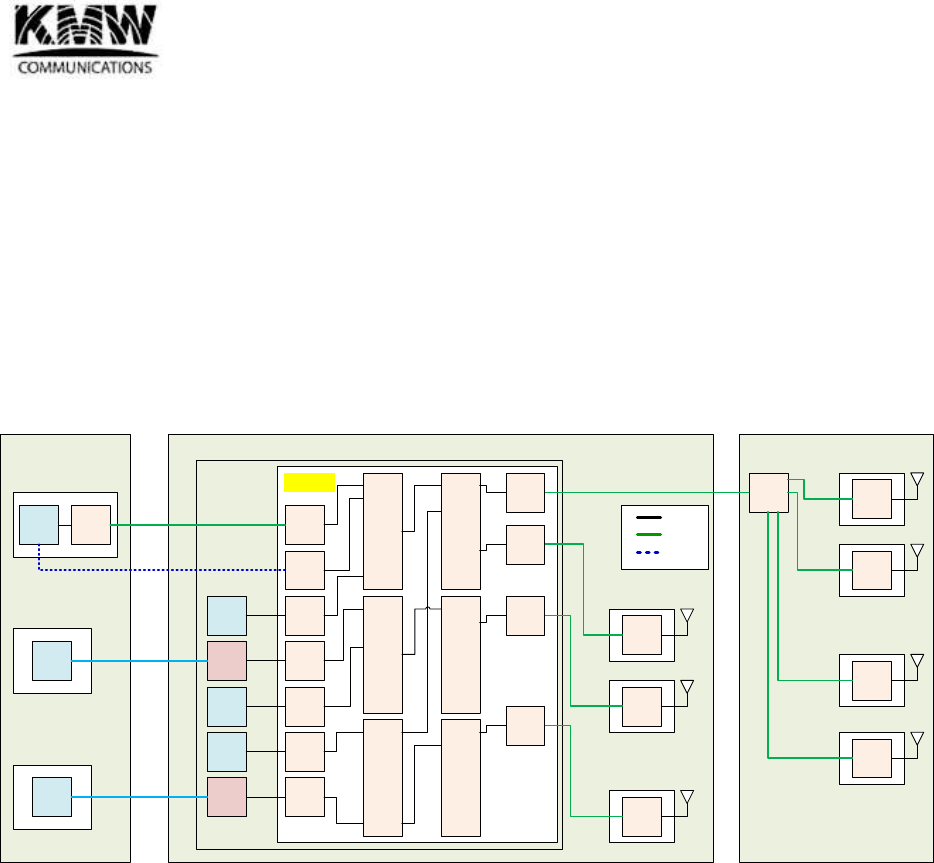
Figure 1-1 represents the overall DAS block diagram of KMW DAS system, POD.
POD consists of HEU (head-end Unit), and RU (Remote unit). HEU provides the interface between plurality of
BTS and plurality of RUs, and RUs are deployed over multiple shadow regions to provide wireless service coverage
to mobile users in shadow regions.
Figure 1-1 DAS Overall Block Diagram
Figure 1-1 shows general signal flow and module composition of POD DAS system.
POD DAS System supports various methods to connect with BTS such as direct connection to BTS through RF
coaxial cable, connection to BTS via antenna through BDA, and connection to BTS by CPRI digital interface over optic.
If user wants air interface with BTS, it is necessary for user to select proper BDA product separately because POD
DAS system does not include any kinds of BDA.
H-FEM provides the interface between various base station having different frequency band/technology and
POD DAS system, and H-COM combines downlink signal received from H-FEM and distributes uplink signals received
from DTM to FEM. H-DTM combines downlink signals from H-COM and then distributes to H-HOM, also combines
uplink signals from several H-HOM and then distributes to H-COM. H-HOM converts downlink RF signal received
from H-DTM to optic signal and then transfers to RU, also converts uplink optic signal received from RU to RF signal
and then transfers to H-DTM. RU provides wireless service coverage to users by transmitting downlink signal received
from H-HOM through the antenna. Also, it transfers to HOM after converting uplink signal received from mobile
stations through the antenna to optic signal.
Remote Sites Building #2Building #1
IDF #3
IDF #2
IDF #1
MDF
Remote Site #2
Remote Site #1
Remote
eNB OIM-B OIM-S
Optic(RF)
FEM
FEMeNB RF
Optic(CPRI)
FEM
RF
BDAeNB Air Interface
FEMeNB RF
FEMeNB RF
Remote Site #3
FEM
RF
BDAeNB Air Interface
COM-8 DTM 8x8
STM 8x4
COM-8 DTM 8x8
DTM 8x8
OEM-S
RU
Optic
Optic
OEM-B
HOM
RU
Optic
HOM
RU
Optic
HOM
IDF #3
IDF #2
IDF #1
RU
RU
RU
Optic
IDF #4
RU
Head-end
MDF: Main Distribution Frame
IDF: Intermediate Distribution Frame
COAX
OPTIC
CPRI
User Manual for POD Systems Revision: 0.7
© KMW USA Inc.
1818 E. Orangethrope Ave, Fullerton, CA 92831
Tel. +1 (714) 515-1100
www.kmwcomm.com
16
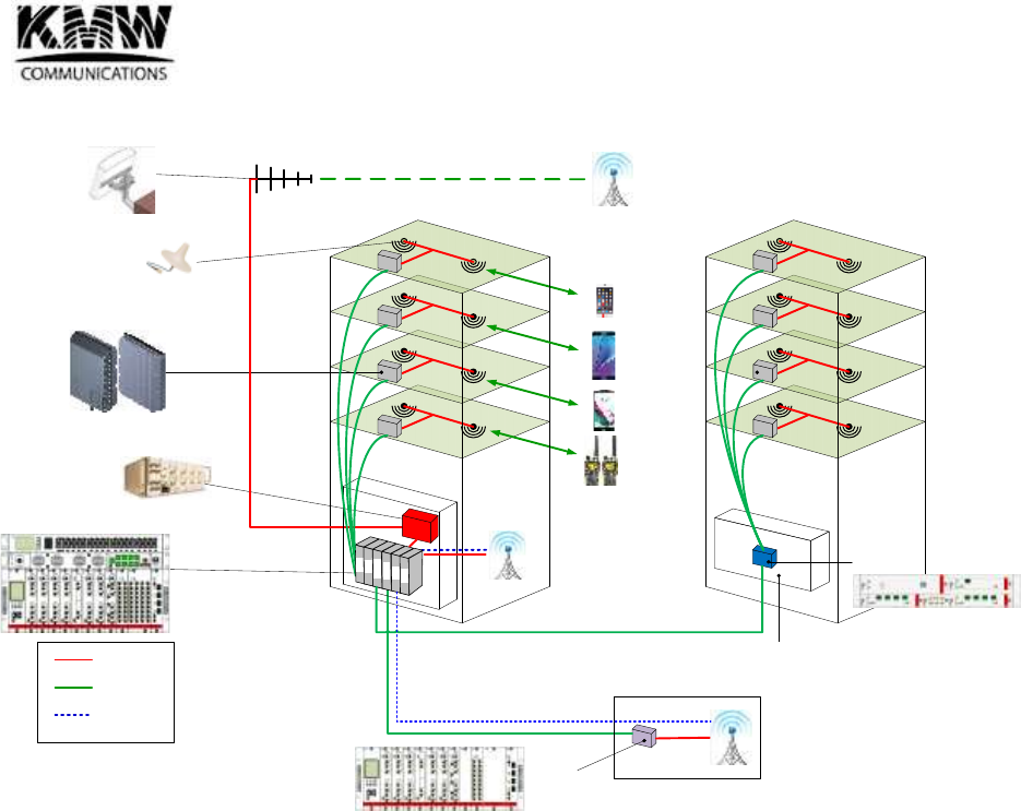
Figure 1-2 How it works
Figure 1-2 is a practical example of POD DAS system. It shows how to distribute various BTS signals from Head-
end Unit to multiple Remote Units.
Especially, in case of buildings away from Head-end location which needs multiple remote units, it is composed
by the structure which distributes to multiple remote units after transmitting signal to other building through only
one optic line using H-OEM, not transmits the signal by individual optic line according to required the number of
remote units.
Also, it supports the connection between Head-end and base station through optic line using H-OIM when base
station is away from head-end location.
Coax
BTS
Bi-directional Amplifier
or Repeater
Coax
OEM-S
Equipment
Room
OEM-S
OIM_B
Optic
BTS
OIM-B
BTS
Air Interface
Server
Antenna
BUILDING #1 BUILDING #2
COAX
OPTIC
CPRI
Head-end
Remote Unit
BDA
HOM
DTM
HOM
DTM
OEM-B
OIM-S
FEM
SCM
Optic
Donor
Antenna
User Manual for POD Systems Revision: 0.7
© KMW USA Inc.
1818 E. Orangethrope Ave, Fullerton, CA 92831
Tel. +1 (714) 515-1100
www.kmwcomm.com
17
1.3 POD System Configuration
1.3.1 SISO Configuration
Assumption
- Supported frequency Band: 700M, SMR800, 850M, PCS, AWS, WCS, 2.6G
- # of RU: 2
System Configuration
Module or Unit
Q’ty
Comments
H-DMCU or H-MCM
1
Main Controller
H-PSU or H-PSM
1
Power Supply Unit
H-FEM-L-7
1
700M
H-FEM-L-S8
1
SMR800
H-FEM-L-C
1
850M
H-FEM-L-P
1
PCS
H-FEM-L-A
1
AWS
H-FEM-L-W
1
WCS
H-FEM-L-B
1
2.6G
H-COM-8
1
H-HOM-L
1
7 band RU
2
Figure 1-3 SISO Configuration
FEM-L-W
UL MON
DL MON
DL Out
UL In
UL MON
DL MON
DL Out
UL In
PWR
ALM
Path A
Path B
KMW
FEM-L-A
UL MON
DL MON
DL Out
UL In
UL MON
DL MON
DL Out
UL In
PWR
ALM
Path A
Path B
KMW
FEM-L-7
UL MON
DL MON
DL Out
UL In
UL Mon
DL MON
DL Out
UL In
PWR
ALM
Path A
Path B
KMW
FEM-L-S8
UL MON
DL MON
DL Out
UL In
UL MON
DL MON
DL Out
UL In
PWR
ALM
Path A
Path B
KMW
FEM-L-C
UL MON
DL MON
DL Out
UL In
UL MON
DL MON
DL Out
UL In
PWR
ALM
Path A
Path B
KMW
FEM-L-B
UL MON
DL MON
DLOut
UL In
UL MON
DL MON
DL Out
UL In
PWR
ALM
Path A
Path B
#1
#2
#3
#4
T-Sync
KMW
FEM-L-P
DL Out
UL MON
UL In
DL MON
PWR
ALM
PCS
KMW
Run Link ALM Reset
ENT Up Down ESC
DMCU Web GUI
SCM
KMW
COM-8
PWR
ALM
DL
COM
#1
#2
#3
#4
#5
#6
#7
#8
#1
#2
#3
#4
#5
#6
#7
#8
UL
COM
DL UL
KMW
HOM-L
PWR
ALM
UL Out
DL In
T_Sync
DL
UL
DL
UL
DL
UL
DL
UL
KMW
# 1
# 2
# 3
# 4
ENT
Up
Down
ESC
Reset
Run
DMCU
Alarm
Link
HE
Alarm
RU
Alarm
1
2
3
4
5 7
6 8
9 11 13 15
10 12 14 16
17 19 21 23
18 20 22 24
25 27 29 31
26 28 30 32
Modem
Web GUI
KMW
DMCU
HPSU
Power
Alarm
#1 #2 #3 #4
#5 #6 #7 #8
DMCU
#1 #2 #3 #4
1 2 1 2
Group Rack
KMW
BLANK
KMW
700M
eNB
SMR800
850M
PCS
AWS
WCS
2.6G
Headend RU
BLANK
KMW
User Manual for POD Systems Revision: 0.7
© KMW USA Inc.
1818 E. Orangethrope Ave, Fullerton, CA 92831
Tel. +1 (714) 515-1100
www.kmwcomm.com
18
1.3.2 MIMO Configuration
Assumption
- Supported frequency Band
SISO: 700M, SMR800, 850M, PCS, AWS, WCS, 2.6G
MIMO: 700M, PCS, AWS, 2.6G
- # of RU: 2
System Configuration
Module or Unit
Q’ty
Comments
H-DMCU or H-MCM
1
Main Controller
H-PSU or H-PSM
1
Power Supply Unit
H-FEM-L-7
1
700M
H-FEM-L-S8
1
SMR800
H-FEM-L-C
1
850M
H-FEM-L-P
2
PCS
H-FEM-L-A
1
AWS
H-FEM-L-W
1
WCS
H-FEM-L-B
1
2.6G
H-COM-8
2
H-HOM-L
2
7 band RU
4
Figure 1-4 MIMO Configuration
FEM-L-W
UL MON
DL MON
DL Out
UL In
UL MON
DL MON
DL Out
UL In
PWR
ALM
Path A
Path B
KMW
FEM-L-A
UL MON
DL MON
DL Out
UL In
UL MON
DL MON
DL Out
UL In
PWR
ALM
Path A
Path B
KMW
FEM-L-7
UL MON
DL MON
DL Out
UL In
UL Mon
DL MON
DL Out
UL In
PWR
ALM
Path A
Path B
KMW
FEM-L-S8
UL MON
DL MON
DL Out
UL In
UL MON
DL MON
DL Out
UL In
PWR
ALM
Path A
Path B
KMW
FEM-L-C
UL MON
DL MON
DL Out
UL In
UL MON
DL MON
DL Out
UL In
PWR
ALM
Path A
Path B
KMW
FEM-L-B
UL MON
DL MON
DLOut
UL In
UL MON
DL MON
DL Out
UL In
PWR
ALM
Path A
Path B
#1
#2
#3
#4
T-Sync
KMW
FEM-L-P
DL Out
UL MON
UL In
DL MON
PWR
ALM
PCS
KMW
Run Link ALM Reset
ENT Up Down ESC
DMCU Web GUI
SCM
KMW
COM-8
PWR
ALM
DL
COM
#1
#2
#3
#4
#5
#6
#7
#8
#1
#2
#3
#4
#5
#6
#7
#8
UL
COM
DL UL
KMW
HOM-L
PWR
ALM
UL Out
DL In
T_Sync
DL
UL
DL
UL
DL
UL
DL
UL
KMW
# 1
# 2
# 3
# 4
ENT
Up
Down
ESC
Reset
Run
DMCU
Alarm
Link
HE
Alarm
RU
Alarm
1
2
3
4
5 7
6 8
9 11 13 15
10 12 14 16
17 19 21 23
18 20 22 24
25 27 29 31
26 28 30 32
Modem
Web GUI
KMW
DMCU
HPSU
Power
Alarm
#1 #2 #3 #4
#5 #6 #7 #8
DMCU
#1 #2 #3 #4
1 2 1 2
Group Rack
KMW
700M
MIMO #2
eNB
PCS
MIMO #2
AWS
MIMO #2
2.6G
MIMO #2
Headend
RU
FEM-L-P
DL Out
UL MON
UL In
DL MON
PWR
ALM
PCS
KMW
700M
MIMO #1
SMR800
850M
PCS
MIMO #1
AWS
MIMO #1
WCS
2.6G
MIMO #1 HOM-L
PWR
ALM
UL Out
DL In
T_Sync
DL
UL
DL
UL
DL
UL
DL
UL
KMW
# 1
# 2
# 3
# 4
MIMO #1 MIMO #2
COM-8
PWR
ALM
DL
COM
#1
#2
#3
#4
#5
#6
#7
#8
#1
#2
#3
#4
#5
#6
#7
#8
UL
COM
DL UL
KMW
User Manual for POD Systems Revision: 0.7
© KMW USA Inc.
1818 E. Orangethrope Ave, Fullerton, CA 92831
Tel. +1 (714) 515-1100
www.kmwcomm.com
19
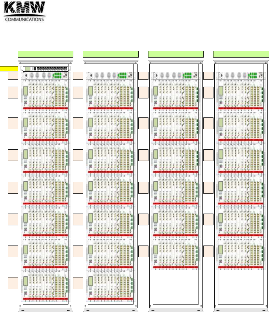
1.4 POD System Scalability & Limitation
Figure 1-5 shows maximum capacity of POD system composed by one DMCU
Figure 1-5 POD System Scalability
SD
ENT
Up
Down
ESC
Reset
Run
DMCU
Alarm
Link
HE
Alarm
RU
Alarm
1
2
3
4
5 7
6 8
9 11 13 15
10 12 14 16
17 19 21 23
18 20 22 24
25 27 29 31
26 28 30 32
Modem
Web GUI
KMW
SD SD SD
Rack #1 Rack #2 Rack #3 Rack #4
SRU
#01
SRU
#02
SRU
#03
SRU
#04
SRU
#05
SRU
#06
SRU
#07
SRU
#08
SRU
#09
SRU
#10
SRU
#11
SRU
#12
SRU
#13
SRU
#14
SRU
#15
SRU
#16
SRU
#17
SRU
#18
SRU
#19
SRU
#20
SRU
#21
SRU
#22
SRU
#23
SRU
#24
SRU
#25
SRU
#26
DMCU
PSU
#1 PSU
#2 PSU
#3 PSU
#4

User Manual for POD Systems Revision: 0.7
© KMW USA Inc.
1818 E. Orangethrope Ave, Fullerton, CA 92831
Tel. +1 (714) 515-1100
www.kmwcomm.com
20
Table 1-1 POD System Scalability & Limitations
Supported maximum number
# of path/Module
POD System1)
/Rack
/H-SRU
H-DMCU
1
RACK
4
H-PSU
4
12)
H-SRU
26
7
H-FEM
H-FEM-L
208
843)
124)
29)
H-FEM-H
1
H-COM-8
26
26
124)
H-DTM 8x8
26
26
64)
HOM
32
28
45)
RU
2566)
2247)
328)
H-OIM-B
4
4
4
H-OEM-S
6
6
6
1) Table 1-1 shows hardware capacity of one POD system.
2) One H-PSU supports one rack with 7 H-SRU which is fully filled with modules.
3) The number of supported H-FEM/rack = 7 H-SRU x 12 H-FEM/H-SRU = 84
4) One H-SRU consists of 12 slots. So, it supports up to 12 modules with 1 slot size (H-FEM & H-COM-8) and 6
modules with 2 slot size (H-DTM 8x8).
5) The number of supported HOM/H-SRU is limited up to four (4).
6) The number of supported RU in POD system is limited up to 256.
7) The number of supported RU/rack = 7 SRU/rack x the number of supported RU/SRU = 224
8) The number of supported RU/H-SRU = 4 HOM/SRU x 4 path/HOM x 2 RU/path = 32
9) H-FEM-L-P (PCS) supports only one path.
User Manual for POD Systems Revision: 0.7
© KMW USA Inc.
1818 E. Orangethrope Ave, Fullerton, CA 92831
Tel. +1 (714) 515-1100
www.kmwcomm.com
21
2. POD SYSTEM COMPONENTS
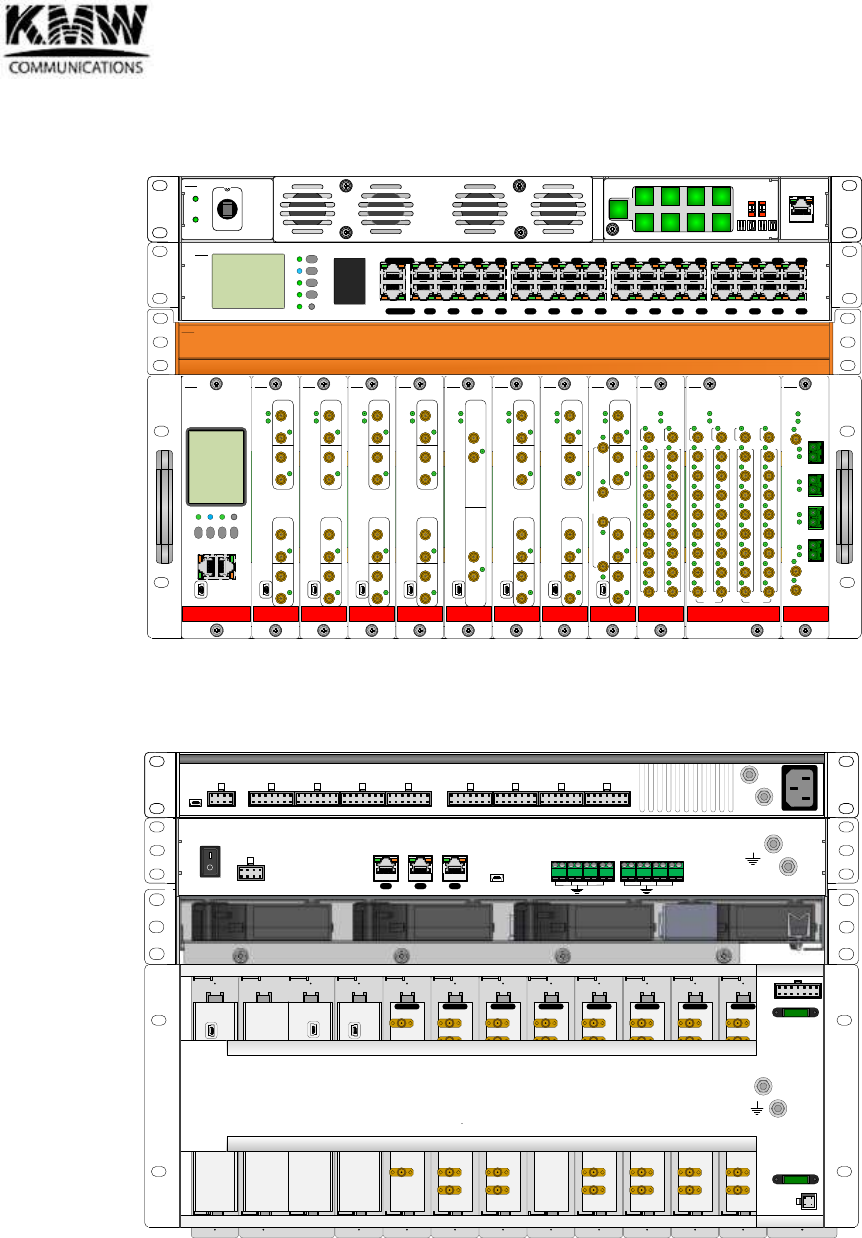
2.1 Head-end Unit
Figure 2-1 Head-end Unit Front View
Figure 2-2 Head-end Unit Rear View
H-SRU
FEM-L-W
UL MON
DL MON
DL Out
UL In
UL MON
DL MON
DL Out
UL In
PWR
ALM
Path A
Path B
KMW
FEM-L-A
UL MON
DL MON
DL Out
UL In
UL MON
DL MON
DL Out
UL In
PWR
ALM
Path A
Path B
KMW
FEM-L-7
UL MON
DL MON
DL Out
UL In
UL Mon
DL MON
DL Out
UL In
PWR
ALM
Path A
Path B
KMW
FEM-L-S8
UL MON
DL MON
DL Out
UL In
UL MON
DL MON
DL Out
UL In
PWR
ALM
Path A
Path B
KMW
FEM-L-P7/P8
UL MON
DL MON
DL Out
UL In
UL MON
DL MON
DL Out
UL In
PWR
ALM
PS700
PS800
KMW
FEM-L-C
UL MON
DL MON
DL Out
UL In
UL MON
DL MON
DL Out
UL In
PWR
ALM
Path A
Path B
KMW
FEM-L-B
UL MON
DL MON
DLOut
UL In
UL MON
DL MON
DL Out
UL In
PWR
ALM
Path A
Path B
#1
#2
#3
#4
T-Sync
KMW
FEM-L-P
DL Out
UL MON
UL In
DL MON
PWR
ALM
PCS
KMW
Run Link ALM Reset
ENT Up Down ESC
DMCU Web GUI
SCM
KMW
COM-8
PWR
ALM
DL
COM
#1
#2
#3
#4
#5
#6
#7
#8
#1
#2
#3
#4
#5
#6
#7
#8
UL
COM
DL UL
KMW
DTM-8x8
PWR
ALM
KMW
VHF
UHF
#1
#2
#3
#4
#5
#6
#7
#8
#1
#2
#3
#4
#5
#6
#7
#8
DL
MON
DL UL
VHF
UHF
#1
#2
#3
#4
#5
#6
#7
#8
#1
#2
#3
#4
#5
#6
#7
#8
UL
MON
IN OUT IN OUT
HOM-L
PWR
ALM
UL Out
DL In
T_Sync
DL
UL
DL
UL
DL
UL
DL
UL
KMW
# 1
# 2
# 3
# 4
SCM [ FEM ] COM-8 DTM-8x8 HOM
1 2 3 4 5 6 7 8 9 10 11 12
KMW
ENT
Up
Down
ESC
Reset
Run
DMCU
Alarm
Link
HE
Alarm
RU
Alarm
1
2
3
4
5 7
6 8
9 11 13 15
10 12 14 16
17 19 21 23
18 20 22 24
25 27 29 31
26 28 30 32
Modem
Web GUI
KMW
DMCU
HPSU
Power
Alarm
#1 #2 #3 #4
#5 #6 #7 #8
DMCU
#1 #2 #3 #4
1 2 1 2
Group Rack
KMW
DMCU
H-PSU
DMCU
H-PSU
H-SRU
SCM[ FEM ]COM-8DTM-8x8HOM
DL / UL (A)
UL Div (A)
DL / UL (B)
UL Div (B)
700M
┌
┌
└
└
DL / UL (A)
UL Div (A)
DL / UL (B)
UL Div (B)
P7/P8
┌
┌
└
└
DL / UL (A)
UL Div (A)
DL / UL (B)
UL Div (B)
S8
┌
┌
└
└
DL / UL (A)
UL Div (A)
DL / UL (B)
UL Div (B)
850M
┌
┌
└
└
DL / UL (A)
UL Div (A)
PCS
┌
┌
DL / UL (A)
UL Div (A)
DL / UL (B)
UL Div (B)
AWS
┌
┌
└
└
DL / UL (A)
UL Div (A)
DL / UL (B)
UL Div (B)
WCS
┌
┌
└
└
DL / UL (A)
DL / UL (B)
BRS
┌
└
- 30 -
- 30 -
#12 #11 #10 #9 #8 #7 #6 #5 #4 #3 #2 #1
HPSU
FUSE
Spare Fuse
FAN
HPSU
Power SW
DMCU
1 2 3
External Alarm
Input Output
1 2 3 4 5 6 7 8
#1 #2 #3 #4 #5 #6 #7 #8
DMCU HSRU

User Manual for POD Systems Revision: 0.7
© KMW USA Inc.
1818 E. Orangethrope Ave, Fullerton, CA 92831
Tel. +1 (714) 515-1100
www.kmwcomm.com
22
Head-end Unit consists of
- H-DMCU (Head-end DAS Main Control Unit)
- H-PSU(Head-end Power Supply Unit)
- H-SRU(Head-end Subrack Unit)
- H-SCM(Head-end Subrack Control Module)
- H-FEM(Head-end Front End Module)
- H-COM(Head-end Combing Module)
- H-DTM(Head-end Distribution Module)
- HOM(Head-end Optic Module)
- H-STM(Head-end Sectorization Module)
- H-OEM(Head-end Optic Expansion Module)
- H-OIM(Head-end Optic Interface Module)
Specification
- Size, weight, and power consumption
Table 2-1 Size, weight, and power consumption (Head-end Unit)
Size(H x W x D)
Weight
Power consumption
(W)
inch
mm
lb
Kg
POD-H-DMCU
2.1 x 19.0 x 19.7
52.4 x 482.6 x
499.5
6.6
3.0
28.5
POD-H-SRU
7.0 x 19.0 x 19.7
177 x 482.6 x 499.5
16.3
7.4
POD-H-SCM
7.0 x 1.8 x 17.8
177 x 46.5 x 452.5
2.9
1.3
16.2
POD-H-MCM
7.0 x 3.1 x 17.8
177 x 79 x 452.5
24.0
POD-H-FEM-L
Refer to Table 2-10
POD-H-FEM-H
Refer to Table 2-14
POD-H-COM-8
7.0 x 1.3 x 17.8
177 x 31.8 x 452.5
5.5
2.5
4.8
POD-H-DTM-8x8
7.0 x 2.5 x 17.8
177 x 64.1 x 452.5
11.5
5.2
12
POD-H-HOM-L
7.0 x 1.3 x 17.8
177 x 31.8 x 452.5
5.5
2.5
30
POD-H-HOM-H
7.0 x 1.3 x 17.8
177 x 31.8 x 452.5
9
4.1
30
POD-H-STM-DL-8x4
7.0 x 2.5 x 17.8
177 x 64.1 x 452.5
11
5
POD-H-STM-UL-8x4
7.0 x 2.5 x 17.8
177 x 64.1 x 452.5
11
5
POD-H-OEM-B
7.0 x 1.3 x 17.8
177 x 31.8 x 452.5
5.3
2.4
30
POD-H-OEM-S
7.0 x 1.3 x 17.8
177 x 31.8 x 452.5
5.5
2.5
30
POD-H-OIM-B
7.0 x 1.3 x 17.8
177 x 31.8 x 452.5
5.3
2.4
30
POD-H-OIM-S
7.0 x 1.3 x 17.8
177 x 31.8 x 452.5
5.5
2.5
30
POD-H-PSU
1.7 x 19.0 x 19.7
44 x 482.6 x 499.5
13.9
6.3
85 @no load
POD-H-PSM
7.0 x 2.5 x 17.8
177 x 64.1 x 452.5
POD-H-CDU
1.4 x 19.0 x 12.0
35.2 x 482.6 x
304.2
2.4
1.1
POD-H-FAU
1.4 x 17.3 x 10.6
36 x 440 x 270
3.5
1.6
12
- Operating temperature: 14 ~ 122F (-10 ~ 50C)
- Power input
H-FEM,H-COM, H-STM, H-DTM, H-HOM, H-OIM, H-FAU: DC 24V
POD-H-PSU-AC/POD-H-PSM-AC: AC 100~240V (47~63Hz)
POD-H-PSU-DC/POD-H-PSM-DC: DC -48V
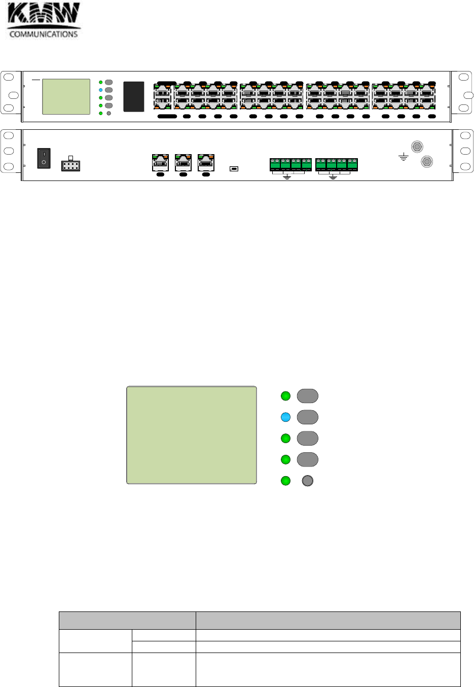
User Manual for POD Systems Revision: 0.7
© KMW USA Inc.
1818 E. Orangethrope Ave, Fullerton, CA 92831
Tel. +1 (714) 515-1100
www.kmwcomm.com
23
2.1.1 POD-H-DMCU (DAS Main Control Unit)
Figure 2-3 POD-H-DMCU
2.1.1.1 Functions and features
- Controls, monitors, and generates alarms for all connected modules and units in a POD DAS system
- Supports up to 4 racks.
- Supports up to 4 H-OIMs and up to 6 H-OEMs.
- Provides web-based GUI interface to user
- Provides the user interface to control and monitor using LCD window and key pad.
- Send alarms to O&M system by SNMP.
- Ethernet port forward function
- Provides external input/output ports for external alarm monitoring
2.1.1.2 Specifications
- Size, weight, and power consumption: refer to Table 2-1
2.1.1.3 LED, LCD & Key PAD, Reset
Figure 2-4 LED, LCD & Key PAD, Reset
LCD window and key pad
- H-DMCU provides the user interface to control and monitor using LCD window and key pad.
Reset
- Used for H-DMCU reset.
LED
Table 2-2 POD-H-DMCU LED Operation
Specifications
Run
Solid Green
When power is on.
OFF
When power is off.
Link
Solid Yellow
When H-DMCU cannot communicate with at least one module
among modules which are directly connected to H-DMCU such as H-
SCM or H-PSU.
ENT
Up
Down
ESC
Reset
Run
DMCU
Alarm
Link
HE
Alarm
RU
Alarm
1
2
3
4
5 7
6 8
9 11 13 15
10 12 14 16
17 19 21 23
18 20 22 24
25 27 29 31
26 28 30 32
Modem
Web GUI
KMW
HPSU
Power SW
DMCU
1 2 3
External Alarm
Input Output
1 2 3 4 5 6 7 8
ENT
Up
Down
ESC
Reset
Run
DMCU
Alarm
Link
HE
Alarm
RU
Alarm
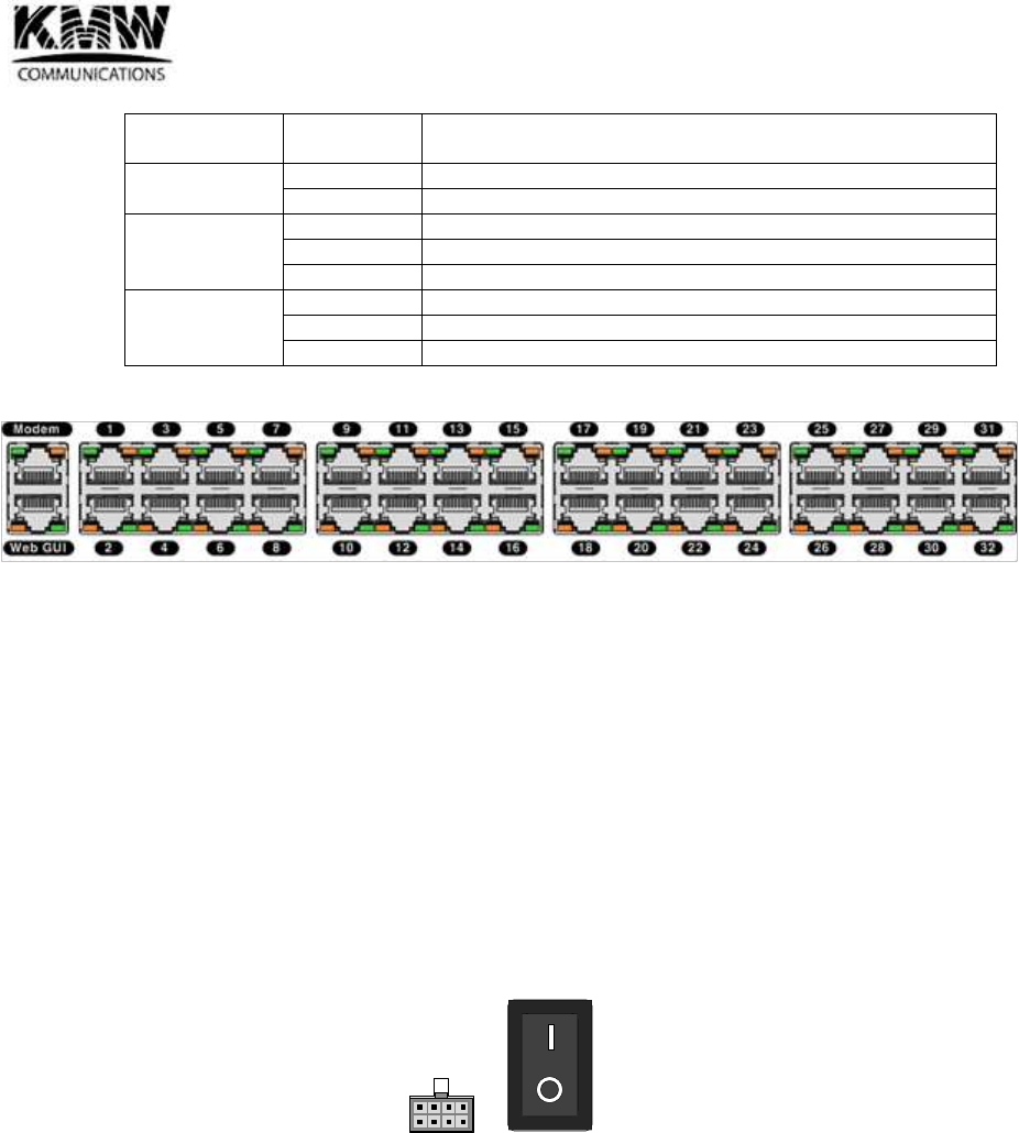
User Manual for POD Systems Revision: 0.7
© KMW USA Inc.
1818 E. Orangethrope Ave, Fullerton, CA 92831
Tel. +1 (714) 515-1100
www.kmwcomm.com
24
OFF
When H-DMCU communicates with all modules which are directly
connected with H-DMCU such as H-SCM or H-PSU.
DMCU Alarm
Solid Yellow
When H-DMCU has minor alarm.
OFF
When H-DMCU has no alarm.
HE Alarm
Solid Yellow
When at least one module or unit in the head-end has minor alarm.
Solid Red
When at least one module or unit in the head-end has major alarm.
OFF
When all modules and units in the head-end have no alarm.
RU Alarm
Solid Yellow
When at least one RU has minor alarm.
Solid Red
When at least one RU has major alarm.
OFF
When all RUs have no alarm.
2.1.1.4 Ethernet Ports
Figure 2-5 Ethernet Ports
Modem port
- Connected to wireless modem which provides connection with O&M center.
Web GUI port
- Used to access to web-based GUI using notebook or desktop PC.
1~32 Ethernet Port
- Connected to H-SRU or H-PSU so that H-DMCU can monitor and control the connected H-PSUs and all
modules installed in H-SRU.
- Connected to external device to provide port forwarding function.
2.1.1.5 DC power input port & power switch
24V DC power for DMCU is fed from POD-H-PSU and can be turned on or off by power switch.
Figure 2-6 DC power input port & power switch
2.1.1.6 External Alarm Port
H-DMCU provides 4 alarm inputs to get the alarm statuses of the connected any external devices. Then, the
input conditions are reported to the O&M system.
H-DMCU also provides 4 alarm outputs to control the external devices or to signal any alarm condition or status
information to the external devices.
HPSU
Power SW
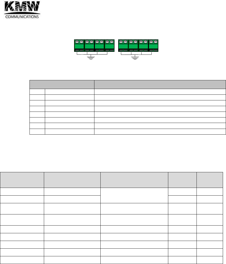
User Manual for POD Systems Revision: 0.7
© KMW USA Inc.
1818 E. Orangethrope Ave, Fullerton, CA 92831
Tel. +1 (714) 515-1100
www.kmwcomm.com
25
Figure 2-7 External Alarm Ports
Table 2-3 Pin map - External Alarm Port
Pin Assign
Specifications
1
External Input #1
External Alarm input #1 pin
2
External Input #2
External Alarm input #2 pin
3
External Input #3
External Alarm input #3 pin
4
External Input #4
External Alarm input #4 pin
5
External Output #1
External Alarm output #1 pin
6
External Output #2
External Alarm output #2 pin
7
External Output #3
External Alarm output #3 pin
8
External Output #4
External Alarm output #4 pin
2.1.1.7 Ground port
- Refer to section 3.2.2
2.1.1.8 Alarms
Table 2-4 POD-H-DMCU - Alarms
Alarm Name
Description
Remedy
Alarm
Severity
LED
color
High Temperature
Temperature high
Check environment
Minor
Yellow
Low Temperature
Temperature too low
Minor
Yellow
Head-end Composite
Head-end composite alarms
Check Head-end unit
Major/Minor
Red/
Yellow
RU Composite
RU composite alarms
Check RU
Major/Minor
Red/
Yellow
External Input (1~4)
External input signal
Check connected external unit
Minor
Yellow
AC Fail
H-PSU AC Fail
Check H-PSU
Major
Red
DC Fail
H-PSU DC Fail
Check H-PSU
Major
Red
PSU Comm. Fail
H-PSU Communication Fail
Check UDP cable connection
Minor
Yellow
SCM Comm. Fail
H-SCM Communication Fail
Check UDP cable connection
Minor
Yellow
External Alarm
Input Output
1 2 3 4 5 6 7 8
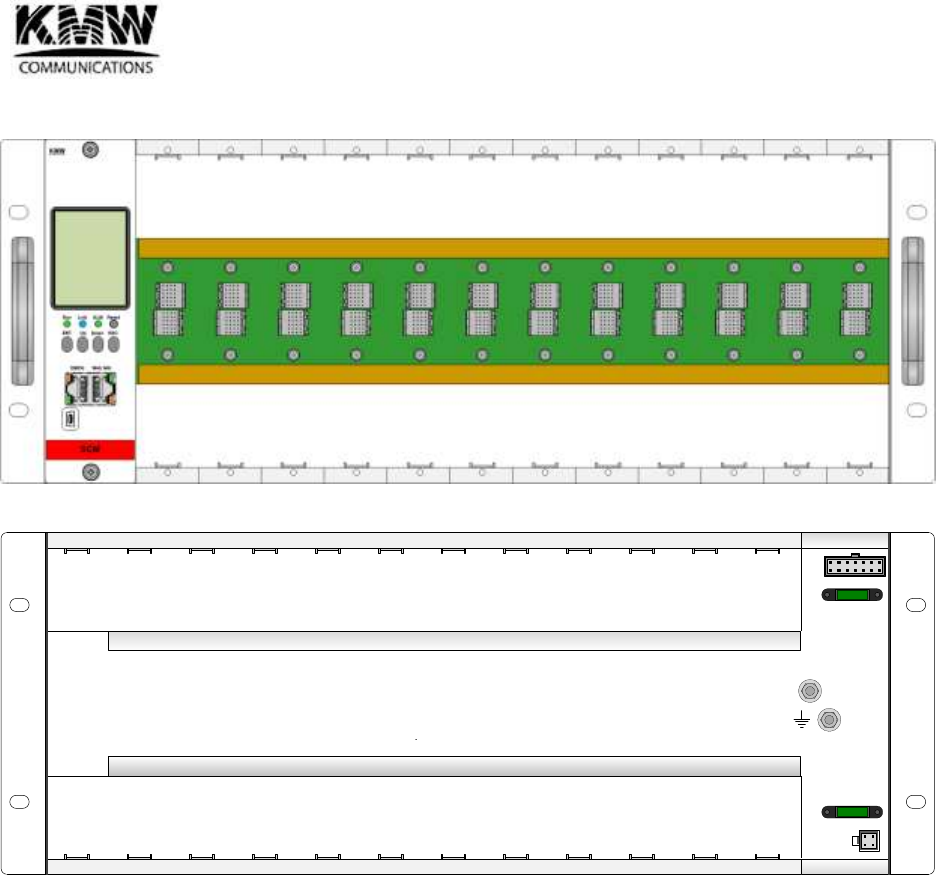
User Manual for POD Systems Revision: 0.7
© KMW USA Inc.
1818 E. Orangethrope Ave, Fullerton, CA 92831
Tel. +1 (714) 515-1100
www.kmwcomm.com
26
2.1.2 POD-H-SRU
Figure 2-8 POD-H-SRU Front View
Figure 2-9 POD-H-SRU Rear View
2.1.2.1 Functions and features
- One H-SRU supports 12 slot including one SCM and other modules such as H-FEM, H-COM, H-DTM, HOM.
- Supplies 24V DC power received from H-PSU to each individual module through the backboard.
- Supplies 24V DC power to H-FAU (Fan Unit) for dissipating heat comes from the modules installed in POD-
H-SRU.
- Provides communication path between installed modules and SCM through backboard.
2.1.2.2 Specifications
- Size, weight, and power consumption : refer to Table 2-1
2.1.2.3 DC input port & Fuse
- 30 -
- 30 -
#12 #11 #10 #9 #8 #7 #6 #5 #4 #3 #2 #1
HPSU
FUSE
Spare Fuse
FAN
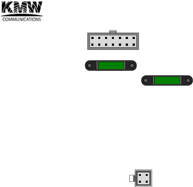
User Manual for POD Systems Revision: 0.7
© KMW USA Inc.
1818 E. Orangethrope Ave, Fullerton, CA 92831
Tel. +1 (714) 515-1100
www.kmwcomm.com
27
Figure 2-10 DC input port & Fuse
DC Input port
- The 24V DC power is supplied from H-PSU through this port, and this port includes H-SRU ID, rack ID which
is set by ‘Rack ID’ dip switch in H-PSU.
FUSE
- Current capacity: 15A
- The fuse protects the damages of all modules installed in H-SRU due to high current.
- H-SRU provides spare fuse for just in case fuse is broken.
2.1.2.4 FAN port
Figure 2-11 FAN port
- DC Power is supplied into the FAN Unit through this port.
- FAN fail alarm is transferred to H-SCM through this port.
2.1.2.5 Ground port
- Refer to section 3.2.2
- 30 -
HPSU
FUSE
- 30 -
Spare Fuse
FAN
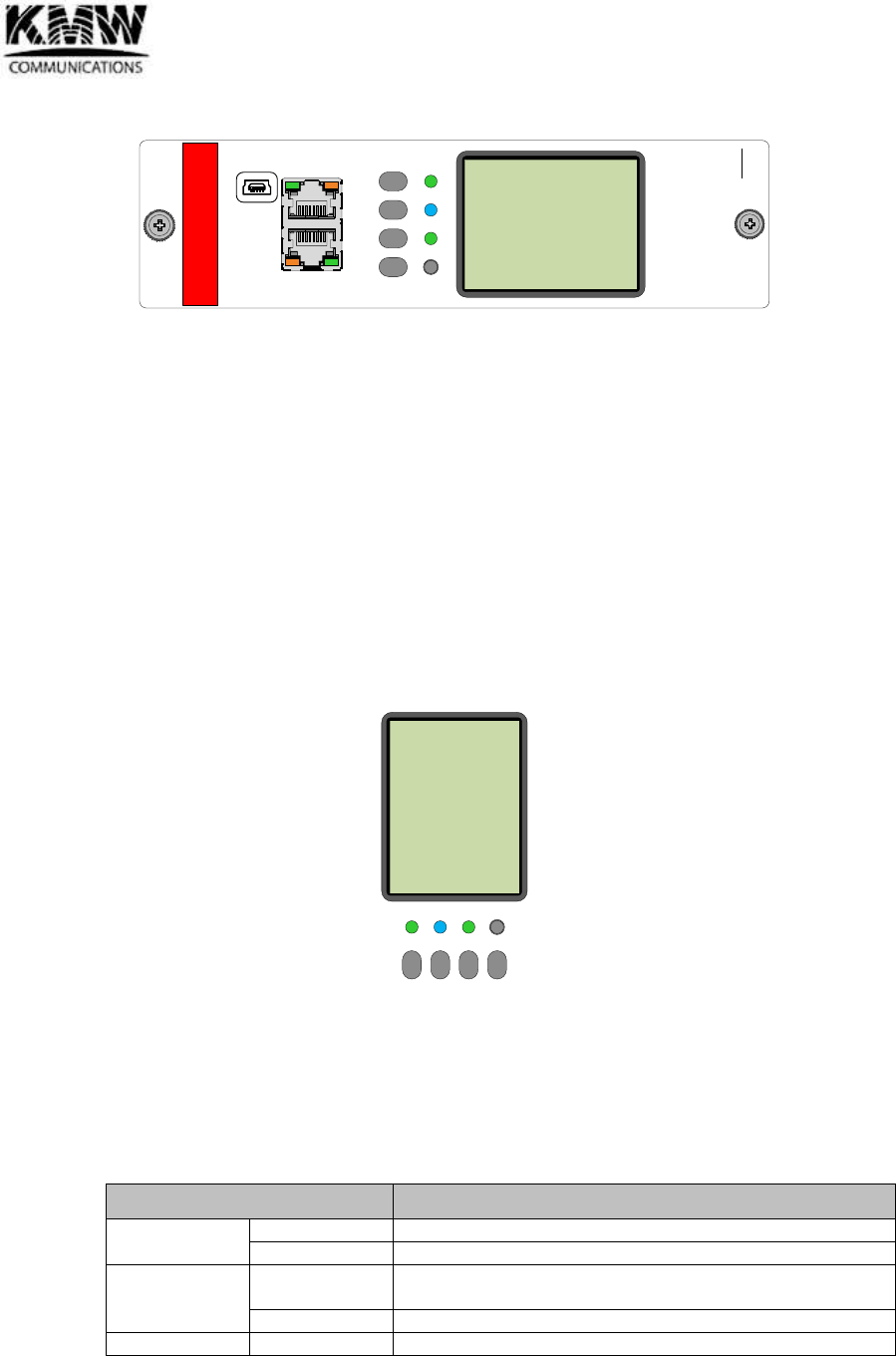
User Manual for POD Systems Revision: 0.7
© KMW USA Inc.
1818 E. Orangethrope Ave, Fullerton, CA 92831
Tel. +1 (714) 515-1100
www.kmwcomm.com
28
2.1.3 POD-H-SCM
Figure 2-12 POD-H-SCM
2.1.3.1 Functions and features
- One H-SCM can be installed in one H-SRU.
- Provides web-based GUI interface to user
- Provides the user interface to control and monitor using LCD window and key pad.
- Provides physical path between H-DMCU and all modules in H-SRU
- Controls FAN on/off and FAN speed and monitors FAN alarm.
- Periodically, gather the data from all modules in H-SRU and send it to H-DMCU through DMCU port.
- Periodically, gather the data from RUs connected to H-HOM in H-SRU and send it to H-DMCU through DMCU
port.
2.1.3.2 Specifications
- Size, weight, and power consumption : refer to Table 2-1
2.1.3.3 LED, LCD & Key PAD, Reset
Figure 2-13 LED, LCD & Key PAD
LCD window and key pad
- H-SCM provides the user interface to control and monitor using LCD window and key pad.
Reset
- Used for H-SCM reset.
Table 2-5 POD-H-SCM LED Operation
Specifications
RUN
Solid Green
When power is on.
OFF
When power is off.
Link
Solid Yellow
When H-SCM cannot communicate with at least one module
among modules installed in H-SRU.
OFF
When H-SCM communicates with all modules installed in H-SRU.
Alarm
Solid Red
When H-SCM has major alarm.
Run Link ALM Reset
ENT Up Down ESC
DMCU Web GUI
SCM
KMW
Run Link ALM Reset
ENT Up Down ESC
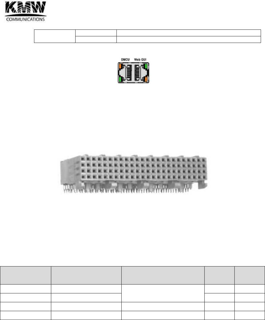
User Manual for POD Systems Revision: 0.7
© KMW USA Inc.
1818 E. Orangethrope Ave, Fullerton, CA 92831
Tel. +1 (714) 515-1100
www.kmwcomm.com
29
Solid Yellow
When H-SCM has minor alarm.
OFF
When H-SCM has no alarm.
2.1.3.4 Ethernet Port
Figure 2-14 Ethernet Port
DMCU port
- Provides physical communication path between H-DMCU and all modules in H-SRU by connecting DMCU
port of H-SCM to available one port among Ethernet port #1~#32 of H-DMCU.
Web GUI port
- Used to access to web-based GUI using notebook or desktop PC.
2.1.3.5 Communication port
Figure 2-15 Communication Port
- This port provides communication path between H-FEM-H-x, H-COM, H-DTM, H-STM, HOM-x or H-SCM
installed in H-SRU through backboard of H-SRU.
- +24V DC is provided through this communication port from backboard of H-SRU.
- H-SCM acquires ID information such as Rack ID, Sub rack ID and Slot ID through this communication port.
The IP address of H-SCM is assigned automatically using the acquired ID information.
2.1.3.6 Alarms
Table 2-6 POD-H-SCM - Alarms
Alarm Name
Description
Remedy
Alarm
Severity
LED
color
High Temperature
Temperature high
Check environment
Minor
Yellow
Low Temperature
Temperature too low
Minor
Yellow
FAN
FAN Fail
Check FAN
Minor
Yellow
Module Comm. Fail
Module Communication Fail
Check Module connection
Minor
Yellow
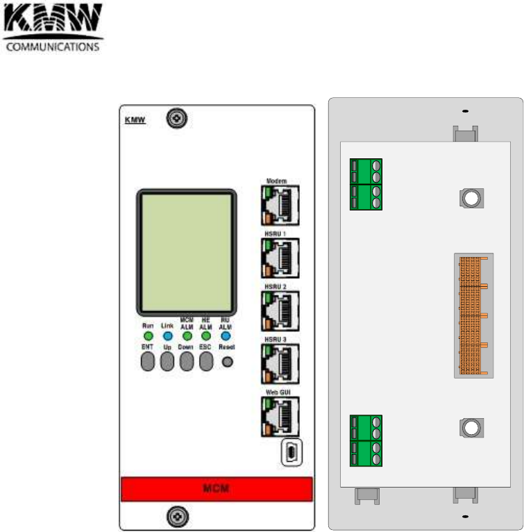
User Manual for POD Systems Revision: 0.7
© KMW USA Inc.
1818 E. Orangethrope Ave, Fullerton, CA 92831
Tel. +1 (714) 515-1100
www.kmwcomm.com
30
2.1.4 POD-H-MCM
Figure 2-16 POD-H-MCM
2.1.4.1 Functions and features
- In case of small size DAS system, H-MCM can replace H-DMCU.
- Controls, monitors, and generates alarms for all modules and units connected to H-MCM via Ethernet cable,
backboard of H-SCM, or optic cable.
- Provides web-based GUI interface to user
- Provides the user interface to control and monitor using LCD window and key pad.
- Send alarms to O&M system by SNMP.
- Input/output ports for external alarm monitoring
2.1.4.2 Specifications
- Size, weight, and power consumption : refer to Table 2-1
2.1.4.3 LED, LCD & Key PAD, Reset
External Alarm
Input
Output
1
2
3
4
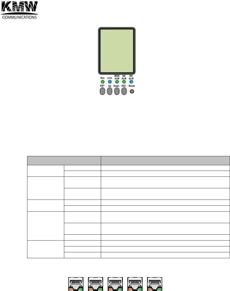
User Manual for POD Systems Revision: 0.7
© KMW USA Inc.
1818 E. Orangethrope Ave, Fullerton, CA 92831
Tel. +1 (714) 515-1100
www.kmwcomm.com
31
Figure 2-17 LED, LCD & Key PAD, Reset
LCD window and key pad
- H-MCM provides the user interface to control and monitor using LCD window and key pad.
Reset
- Used for H-MCM reset.
LED
Table 2-7 POD-H-MCM LED Operation
Specifications
Run
Solid Green
When power is on.
OFF
When power is off.
Link
Blink Green
When H-MCM cannot communicate with at least one module or
units connected to H-MCM.
OFF
When H-MCM communicates all modules and units connected to
H-MCM.
MCM Alarm
Blink Green
When H- MCM itself has minor alarm.
OFF
When H- MCM itself has no alarm.
HE Alarm
Blink Green
When at least one module or unit connected to H-MCM has
minor alarm.
Solid Red
When at least one module or unit connected to H-MCM has
major alarm.
OFF
When all modules and units connected to H-MCM have no alarm.
RU Alarm
Blink Green
When at least one RU connected to H-MCM has minor alarm.
Solid Red
When at least one RU connected to H-MCM has major alarm.
OFF
When all RUs connected to H-MCM have no alarm.
2.1.4.4 Ethernet Ports
Figure 2-18 Ethernet ports
Modem port
- Connected to wireless modem which provides connection with O&M center.
Web GUI port
- Used to access to web-based GUI using notebook or desktop PC.
HSRU1~HSRU3 Ethernet Port
- Connected to H-SRU so that H-MCM can monitor and control the connected all modules installed in H-SRU.
HSRU 1
HSRU 2
HSRU 3
Modem
Web GUI
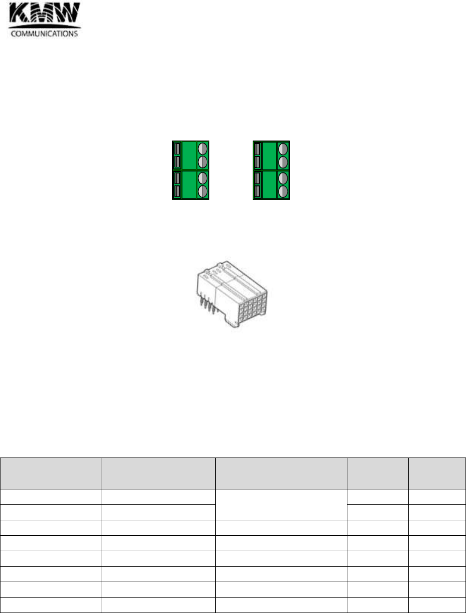
User Manual for POD Systems Revision: 0.7
© KMW USA Inc.
1818 E. Orangethrope Ave, Fullerton, CA 92831
Tel. +1 (714) 515-1100
www.kmwcomm.com
32
2.1.4.5 External Alarm Ports
POD-H-MCM provides 2 alarm inputs to get the alarm statuses of the connected any external devices. Then, the
input conditions are reported to the O&M system.
POD-H-MCM also provides 2 alarm outputs to control the external devices or to signal any alarm condition or
status information to the external devices.
Figure 2-19 External Alarm Ports
2.1.4.6 Communication port
Figure 2-20 Communication Port
- This port provides communication path between H-FEM-H-x, H-COM, H-DTM, H-STM, HOM-x or H-SCM
installed in H-SRU through backboard of H-SRU.
- +24V DC is provided through this communication port from backboard of H-SRU.
- H-MCM acquires ID information such as Rack ID, Sub rack ID and Slot ID through this communication port.
The IP address of H-MCM is assigned automatically using the acquired ID information.
2.1.4.7 Alarms
Table 2-8 POD-H-MCM - Alarms
Alarm Name
Description
Remedy
Alarm
Severity
LED
color
High Temperature
Temperature high
Check environment
Minor
Yellow
Low Temperature
Temperature too low
Minor
Yellow
Head-end Composite
Head-end composite alarms
Check Head-end unit
Major/Minor
Red/ Yellow
RU Composite
RU composite alarms
Check RU
Major/Minor
Red/ Yellow
External Input (1~2)
External input signal
Check connected External unit
Minor
Yellow
AC Fail
H-PSU AC Fail
Check H-PSU
Major
Red
DC Fail
H-PSU DC Fail
Check H-PSU
Major
Red
SCM Comm. Fail
H-SCM Communication Fail
Check UDP cable connection
Minor
Yellow
External Alarm
Input
1
2
Output
3
4
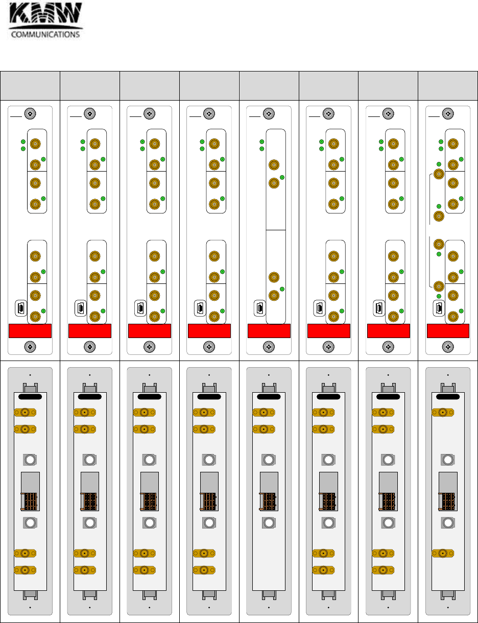
User Manual for POD Systems Revision: 0.7
© KMW USA Inc.
1818 E. Orangethrope Ave, Fullerton, CA 92831
Tel. +1 (714) 515-1100
www.kmwcomm.com
33
2.1.5 POD-H-FEM-L-x
FEM-L-7
FEM-L-
P7/P8
FEM-L-S8
FEM-L-C
FEM-L-P
FEM-L-A
FEM-L-W
FEM-L-B
Figure 2-21 POD-H-FEM-L-x Front & Rear View
FEM-L-7
UL MON
DL MON
DL Out
UL In
UL Mon
DL MON
DL Out
UL In
PWR
ALM
Path A
Path B
KMW
FEM-L-P7/P8
UL MON
DL MON
DL Out
UL In
UL MON
DL MON
DL Out
UL In
PWR
ALM
PS700
PS800
KMW
FEM-L-S8
UL MON
DL MON
DL Out
UL In
UL MON
DL MON
DL Out
UL In
PWR
ALM
Path A
Path B
KMW
FEM-L-C
UL MON
DL MON
DL Out
UL In
UL MON
DL MON
DL Out
UL In
PWR
ALM
Path A
Path B
KMW
FEM-L-P
DL Out
UL MON
UL In
DL MON
PWR
ALM
PCS
KMW
FEM-L-A
UL MON
DL MON
DL Out
UL In
UL MON
DL MON
DL Out
UL In
PWR
ALM
Path A
Path B
KMW
FEM-L-W
UL MON
DL MON
DL Out
UL In
UL MON
DL MON
DL Out
UL In
PWR
ALM
Path A
Path B
KMW
FEM-L-B
UL MON
DL MON
DLOut
UL In
UL MON
DL MON
DL Out
UL In
PWR
ALM
Path A
Path B
#1
#2
#3
#4
T-Sync
KMW
DL / UL (A)
UL Div (A)
DL / UL (B)
UL Div (B)
700M
┌
┌
└
└
DL / UL (A)
UL Div (A)
DL / UL (B)
UL Div (B)
P7/P8
┌
┌
└
└
DL / UL (A)
UL Div (A)
DL / UL (B)
UL Div (B)
S8
┌
┌
└
└
DL / UL (A)
UL Div (A)
DL / UL (B)
UL Div (B)
850M
┌
┌
└
└
DL / UL (A)
UL Div (A)
PCS
┌
┌
DL / UL (A)
UL Div (A)
DL / UL (B)
UL Div (B)
AWS
┌
┌
└
└
DL / UL (A)
UL Div (A)
DL / UL (B)
UL Div (B)
WCS
┌
┌
└
└
DL / UL (A)
DL / UL (B)
BRS
┌
└

User Manual for POD Systems Revision: 0.7
© KMW USA Inc.
1818 E. Orangethrope Ave, Fullerton, CA 92831
Tel. +1 (714) 515-1100
www.kmwcomm.com
34
2.1.5.1 Functions and features
- Provides the interface between DAS and Base station
- Provides independent two RF path except H-FEM-L-P
- ALC function for DL/UL Path
- Spectrum monitoring function for DL Input
- TDD Switching for TD-LTE (POD-H-FEM-L-B only)
- Acquisition and transmission of synchronization signal (POD-H-FEM-L-B only)
2.1.5.2 Specifications
- Frequency range
Table 2-9 POD-H-FEM-L-x frequency range
Downlink
Uplink
Comments
POD-H-FEM-L-7
728~756 MHz
698~716 MHz (Lower ABC)
777~787 MHz (Upper C)
POD-H-FEM-L-P7P8
758~775 MHz (PS700)
851~869 MHz (PS800)
788~805 MHz (PS700)
806~824 MHz (PS800)
POD-H-FEM-L-S8
851~869 MHz
806~824 MHz
POD-H-FEM-L-C
869~894 MHz
824~849 MHz
POD-H-FEM-L-P
1930~1995 MHz
1850~1915 MHz
POD-H-FEM-L-A
2110~2180 MHz
1710~1780 MHz
POD-H-FEM-L-W
2350~2360 MHz
2305~2315 MHz
POD-H-FEM-L-B
2496~2690 MHz
TDD
- Input range
-15~20dBm
Table 2-10 POD-H-FEM-L-x Size, weight, and power consumption
Size(H x W x D)
Weight
Power consumption
(W)
inch
mm
lb
Kg
POD-H-FEM-L-7
7.0 x 1.3 x 17.8
177 x 31.8 x 452.5
4.9
2.2
22
POD-H-FEM-L-P7P8
7.0 x 1.3 x 17.8
177 x 31.8 x 452.5
4.9
2.2
16
POD-H-FEM-L-S8
7.0 x 1.3 x 17.8
177 x 31.8 x 452.5
4.9
2.2
16
POD-H-FEM-L-C
7.0 x 1.3 x 17.8
177 x 31.8 x 452.5
4.9
2.2
15
POD-H-FEM-L-P
7.0 x 1.3 x 17.8
177 x 31.8 x 452.5
4.9
2.2
9
POD-H-FEM-L-A
7.0 x 1.3 x 17.8
177 x 31.8 x 452.5
4.9
2.2
12
POD-H-FEM-L-W
7.0 x 1.3 x 17.8
177 x 31.8 x 452.5
4.9
2.2
12
POD-H-FEM-L-B
7.0 x 1.3 x 17.8
177 x 31.8 x 452.5
4.9
2.2
13
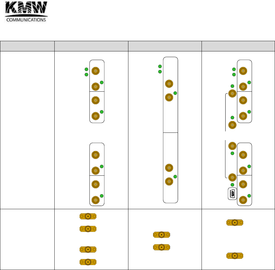
User Manual for POD Systems Revision: 0.7
© KMW USA Inc.
1818 E. Orangethrope Ave, Fullerton, CA 92831
Tel. +1 (714) 515-1100
www.kmwcomm.com
35
2.1.5.3 RF Port and LED
H-FEM-L-7/P7P8/S8/C/A/W
H-FEM-L-P
H-FEM-L-B
Front Panel
Rear Panel
Figure 2-22 POD-H-FEM-L-x RF port and LED
RF Ports
- DL/UL-A(B), UL-Div A(B)
Linked to BTS RF ports
When the RF port linked to BTS is duplex port, connect to DL/UL-A(B)
When the RF ports linked to BTS are TX/RX port, connect DL/UL-A(B) to TX port and UL Div A(B) to RX
port.
Connector Type: SMA Female
- Connector Type: SMA DL MON-A(B), UL MON-A(B)
Used to monitor DL input or UL output for path A or B
Connector Type: SMB-L Female
- DL OUT-A(B), UL IN-A(B)
DL OUT- A(B): DL output port for path A or B, Linked to H-COM or H-DTM
UL IN- A(B): UL input port for path A or B, Linked to H-COM or H-DTM
Connector Type: SMB-L Female
UL MON
DL MON
DL Out
UL In
UL MON
DL MON
DL Out
UL In
PWR
ALM
Path A
Path B
DL Out
UL MON
UL In
DL MON
PWR
ALM
UL MON
DL MON
DLOut
UL In
UL MON
DL MON
DL Out
UL In
PWR
ALM
Path A
Path B
#1
#2
#3
#4
T-Sync
DL / UL (A)
UL Div (A)
DL / UL (B)
UL Div (B)
DL / UL (A)
UL Div (A)
DL / UL (A)
DL / UL (B)
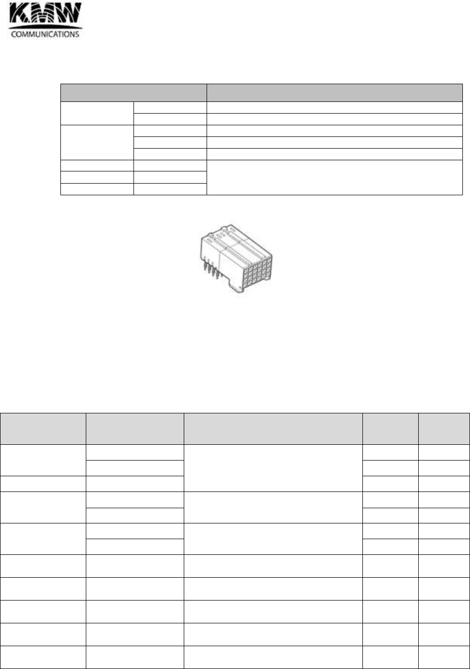
User Manual for POD Systems Revision: 0.7
© KMW USA Inc.
1818 E. Orangethrope Ave, Fullerton, CA 92831
Tel. +1 (714) 515-1100
www.kmwcomm.com
36
LED
Table 2-11 POD-H-FEM-L-x LED Operation
Specifications
PWR
Solid Green
When power is on.
Off
When power is off.
ALM
Off
When H-FEM-L-x has no alarms.
Solid Yellow
When H-FEM-L-x has minor alarm.
Solid Red
When H-FEM-L-x has major alarm.
DL Out
Blink Green
At the cable connection guide, green led blinks to indicate which
RF ports should be connected to.
UL In
Blink Green
T-sync #1~#4
Blink Green
2.1.5.4 Communication port
Figure 2-23 Communication Port
- This port provides communication path between H-FEM-L-x and H-SCM through backboard of H-SRU.
- +24V DC is provided through this communication port from backboard of H-SRU.
- H-FEM-L-x acquires ID information such as Rack ID, Sub rack ID and Slot ID through this communication port.
The IP address of H-FEM-L-x is assigned automatically using the acquired ID information.
2.1.5.5 Alarms
Table 2-12 POD-H-FEM-L-x - Alarms
Alarm Name
Description
Remedy
Alarm
Severity
LED
color
High Temperature
Temperature too high
Check environment
Major
Red
Temperature high
Minor
Yellow
Low Temperature
Temperature too low
Minor
Yellow
Downlink High Input
power
RF signal too high
Check H-FEM downlink input level/
attenuator configuration/ALC status
Major
Red
RF signal high
Major
Yellow
Uplink High Output
Power
RF signal too high
Check H-FEM uplink input level/ attenuator
configuration/ALC status
Major
Red
RF signal high
Major
Yellow
Downlink Low Input
Power
RF signal too low
Check H-FEM downlink input level/
attenuator configuration/RF cabling
Minor
Yellow
Link
Communication fail
Check pin of communication port/ assigned
IP address
Major
Yellow
Freeze
The final stage of
Shutdown process
Check if shutdown process is going again
after reset
Major
Red
Downlink ALC
Activation
ALC activation
Check H-FEM downlink input level/
attenuator configuration
Warning
Yellow
Sync fail
(H-FEM-L-B only)
No TDD sync signal is
acquired
Check H-FEM downlink signal input received
from BTS
Major
Yellow
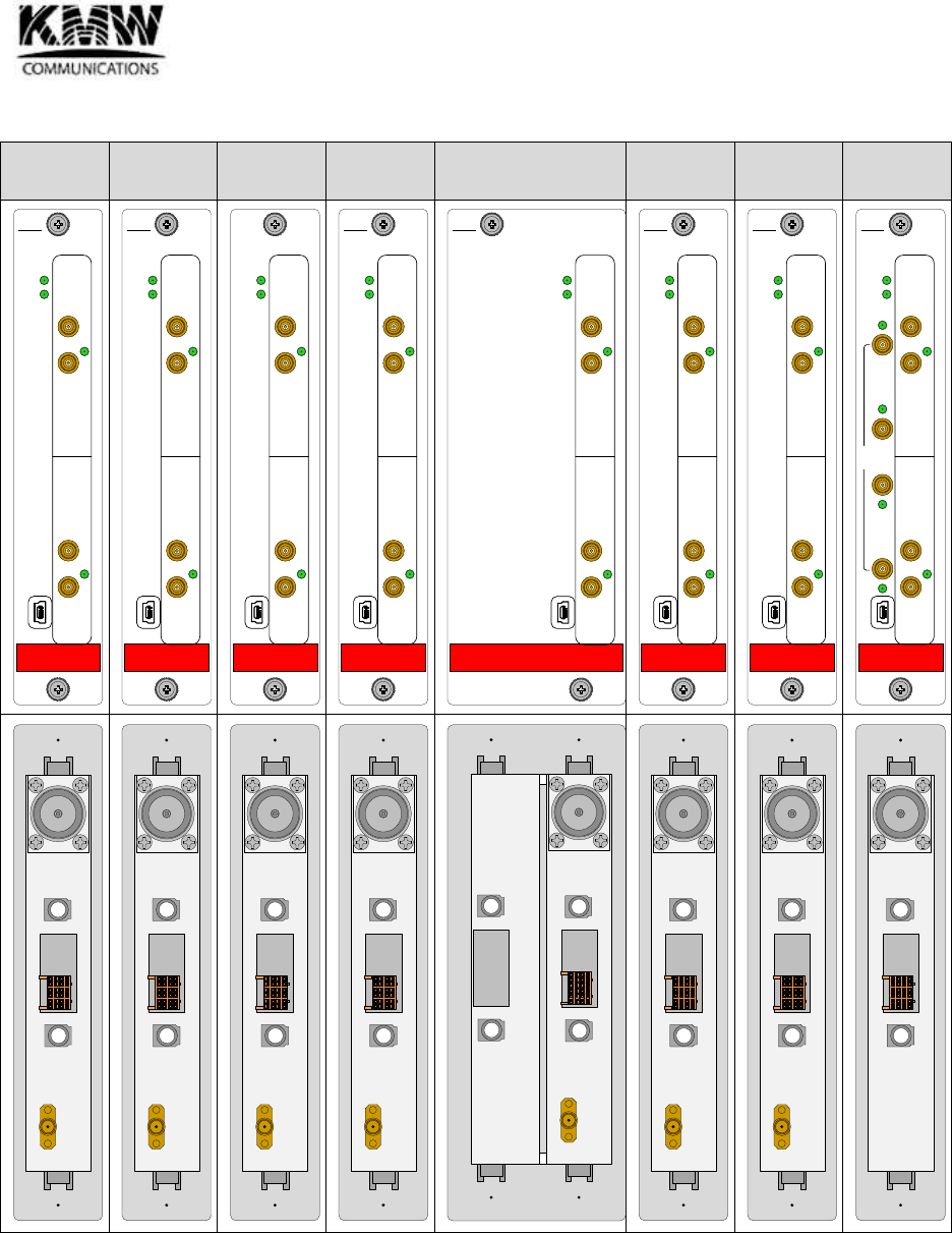
User Manual for POD Systems Revision: 0.7
© KMW USA Inc.
1818 E. Orangethrope Ave, Fullerton, CA 92831
Tel. +1 (714) 515-1100
www.kmwcomm.com
37
2.1.6 POD-H-FEM-H-x
FEM-H-7
FEM-H-P7
FEM-H-
S8(P8)
FEM-H-C
FEM-H-P
FEM-H-A
FEM-H-W
FEM-H-B
Figure 2-24 POD-H-FEM-H-x Front & Rear View
FEM-H-7
DL Out
UL MON
UL In
DL MON
PWR
ALM
700M
KMW
FEM-H-P7
DL Out
UL MON
UL In
DL MON
PWR
ALM
PS700
KMW
FEM-H-S8
DL Out
UL MON
UL In
DL MON
PWR
ALM
SMR800
FEM-H-C
DL Out
UL MON
UL In
DL MON
PWR
ALM
850M
KMW
FEM-H-P
KMW
DL Out
UL MON
UL In
DL MON
PWR
ALM
PCS
FEM-H-A
DL Out
UL MON
UL In
DL MON
PWR
ALM
AWS
KMW
FEM-H-W
DL Out
UL MON
UL In
DL MON
PWR
ALM
WCS
KMW
FEM-H-B
DL Out
UL MON
UL In
DL MON
PWR
ALM
BRS
KMW
#1
#2
#3
#4
T-Sync
UL Div
UL Div
UL Div
UL Div
UL Div
UL Div
UL Div

User Manual for POD Systems Revision: 0.7
© KMW USA Inc.
1818 E. Orangethrope Ave, Fullerton, CA 92831
Tel. +1 (714) 515-1100
www.kmwcomm.com
38
2.1.6.1 Functions and features
- Provides the interface between DAS and Base station
- ALC function for DL/UL Path
- Spectrum monitoring function for DL Input
- TDD Switching for TD-LTE (POD-H-FEM-H-B only)
- Acquisition and transmission of synchronization signal (POD-H-FEM-H-B only)
2.1.6.2 Specifications
Frequency range
Table 2-13 POD-H-FEM-H-x frequency range
Downlink
Uplink
Comments
POD-H-FEM-L-7
728~756 MHz
698~716 MHz (Lower ABC)
777~787 MHz (Upper C)
POD-H-FEM-L-P7
758~775 MHz
788~805 MHz
POD-H-FEM-L-P8
851~869 MHz
806~824 MHz
POD-H-FEM-L-S8
851~869 MHz
806~824 MHz
POD-H-FEM-L-C
869~894 MHz
824~849 MHz
POD-H-FEM-L-P
1930~1995 MHz
1850~1915 MHz
POD-H-FEM-L-A
2110~2180 MHz
1710~1780 MHz
POD-H-FEM-L-W
2350~2360 MHz
2305~2315 MHz
POD-H-FEM-L-B
2496~2690 MHz
TDD
Input range
- 15~46dBm
Table 2-14 POD-H-FEM-H-x Size, weight, and power consumption
Size(H x W x D)
Weight
Power consumption
(W)
inch
mm
lb
Kg
POD-H-FEM-H-7
7.0 x 1.3 x 17.8
177 x 31.8 x 452.5
5.7
2.6
11.5
POD-H-FEM-H-P7
7.0 x 1.3 x 17.8
177 x 31.8 x 452.5
5.7
2.6
8
POD-H-FEM-H-P8(S8)
7.0 x 1.3 x 17.8
177 x 31.8 x 452.5
5.7
2.6
8
POD-H-FEM-H-C
7.0 x 1.3 x 17.8
177 x 31.8 x 452.5
5.7
2.6
8
POD-H-FEM-H-P
7.0 x 2.5 x 17.8
177 x 63.8 x 452.5
5.7
2.6
9
POD-H-FEM-H-A
7.0 x 1.3 x 17.8
177 x 31.8 x 452.5
7.7
3.5
9.5
POD-H-FEM-H-W
7.0 x 1.3 x 17.8
177 x 31.8 x 452.5
5.7
2.6
6
POD-H-FEM-H-B
7.0 x 1.3 x 17.8
177 x 31.8 x 452.5
5.7
2.6
6
POD-H-FEM-L-B
7.0 x 1.3 x 17.8
177 x 31.8 x 452.5
5.7
2.6
7.5
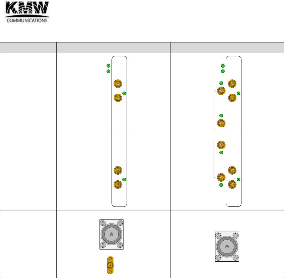
User Manual for POD Systems Revision: 0.7
© KMW USA Inc.
1818 E. Orangethrope Ave, Fullerton, CA 92831
Tel. +1 (714) 515-1100
www.kmwcomm.com
39
2.1.6.3 RF port and LED
H-FEM-L-7/P7/P8/S8/C/P/A/W
H-FEM-L-B
Front Panel
Rear Panel
Figure 2-25 POD-H-FEM-H-x RF port and LED
RF Ports
- DL/UL, UL-Div
Linked to BTS RF ports
When the RF port linked to BTS is duplex port, connect to DL/UL
When the RF ports linked to BTS are TX/RX port, connect DL/UL to TX port and UL Div to RX port.
Connector Type
Mini DIN Female for DL/UL port
SMA Female for UL div port
- Connector Type: SMA DL MON, UL MON
Used to monitor DL input or UL output
Connector Type: SMB-L Female
- DL OUT, UL IN
DL OUT: DL output port, Linked to H-COM or H-DTM
UL IN: UL input port, Linked to H-COM or H-DTM
Connector Type: SMB-L Female
DL Out
UL MON
UL In
DL MON
PWR
ALM
DL Out
UL MON
UL In
DL MON
PWR
ALM
#1
#2
#3
#4
T-Sync
UL Div
DL/UL
DL/UL

User Manual for POD Systems Revision: 0.7
© KMW USA Inc.
1818 E. Orangethrope Ave, Fullerton, CA 92831
Tel. +1 (714) 515-1100
www.kmwcomm.com
40
LED
Table 2-15 POD-H-FEM-H-x LED Operation
Specifications
PWR
Solid Green
When power is on.
Off
When power is off.
ALM
Off
When H-FEM-H-x has no alarms.
Solid Yellow
When H-FEM-H-x has minor alarm.
Solid Red
When H-FEM-H-x has major alarm.
DL Out
Blink Green
At the cable connection guide, green led blinks to indicate which
RF ports should be connected to.
UL In
Blink Green
T-sync #1~#4
Blink Green
2.1.6.4 Communication port
Figure 2-26 Communication Port
- This port provides communication path between H-FEM-H-x and H-SCM through backboard of H-SRU.
- +24V DC is provided through this communication port from backboard of H-SRU.
- H-FEM-H-x acquires ID information such as Rack ID, Sub rack ID and Slot ID through this communication
port. The IP address of H-FEM-H-x is assigned automatically using the acquired ID information.
2.1.6.5 Alarms
Table 2-16 POD-H-FEM-H-x - Alarms
Alarm Name
Description
Remedy
Alarm
Severity
LED
color
High Temperature
Temperature too high
Check environment
Major
Red
Temperature high
Minor
Yellow
Low Temperature
Temperature too low
Minor
Yellow
Downlink High Input
Power
RF signal too high
Check H-FEM downlink input level/
attenuator configuration/ALC status
Major
Red
RF signal high
Major
Yellow
Uplink High Output
Power
RF signal too high
Check H-FEM uplink input level/ attenuator
configuration/ALC status
Major
Red
RF signal high
Major
Yellow
Downlink Low Input
Power
RF signal too low
Check H-FEM downlink input level/
attenuator configuration/RF cabling
Minor
Yellow
Link
Communication fail
Check pin of communication port/ assigned
IP address
Major
Yellow
Freeze
The final stage of
Shutdown process
Check if shutdown process is going again
after reset
Major
Red
Downlink ALC
Activation
ALC activation
Check H-FEM downlink input level/
attenuator configuration
Warning
Yellow
Sync fail
(H-FEM-L-B only)
No TDD sync signal is
acquired
Check H-FEM downlink signal input received
from BTS
Major
Yellow
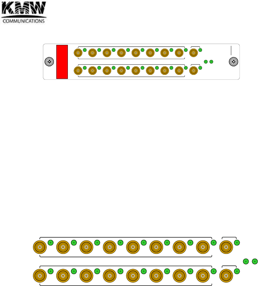
User Manual for POD Systems Revision: 0.7
© KMW USA Inc.
1818 E. Orangethrope Ave, Fullerton, CA 92831
Tel. +1 (714) 515-1100
www.kmwcomm.com
41
2.1.7 POD-H-COM-8
Figure 2-27 POD-H-COM-8
2.1.7.1 Functions and features
- Combines DL output signals received from H-FEM and transfers to H-DTM, or H-HOM
- Receives UL signal from H-DTM, or H-HOM and distributes to H-FEM
- Control Power Ratio for multiple H-FEM with same frequency band to share DL output power at RU
- ALC function for DL/UL Path
- To minimize negative effects by unused input/output ports such as the degradation of VSWR or isolation
between ports, the unused ports can be switched into 50 ohm termination by user.
- When any one sector or DAS system needs low power RU less than 4, H-COM can be connected to H-HOM-
L directly without H-DTM.
In this case, the attenuator in the common path of H-COM should add 15dB attenuation using web
based GUI to compensate the loss of H-DTM..
2.1.7.2 Specifications
- Frequency range: 600~2700MHz
- Maximum RF Power: -10dBm@DL, -25dBm@UL
- Size, weight, and power consumption : refer to Table 2-1
2.1.7.3 RF port and LED
Figure 2-28 POD-H-COM-8 RF port and LED
RF Port
- DL #1 ~ #8
Receives downlink signal from up to 8 H-FEM
Connected to DL output port of H-FEM
Connector Type: SMB-L Female
- DL COM
Combines inputted downlink signals from DL #1 to DL #8 and outputs to H-DTM or H-HOM
Connected to DL input port of H-DTM, or H-HOM
Connector Type: SMB-L Female
- UL COM
Receives uplink signal from H-DTM or H-HOM
Connected to UL output port of H-DTM, or H-HOM
Connector Type: SMB-L Female
- UL #1 ~ #8
Divides inputted uplink signals from UL COM port and outputs to H-FEM
COM-8
PWR
ALM
DL
COM
#1
#2
#3
#4
#5
#6
#7
#8
#1
#2
#3
#4
#5
#6
#7
#8
UL
COM
DL UL
KMW
PWR
ALM
DL
COM
#1
#2
#3
#4
#5
#6
#7
#8
#1
#2
#3
#4
#5
#6
#7
#8
UL
COM
DL UL
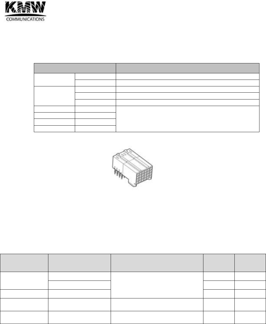
User Manual for POD Systems Revision: 0.7
© KMW USA Inc.
1818 E. Orangethrope Ave, Fullerton, CA 92831
Tel. +1 (714) 515-1100
www.kmwcomm.com
42
Connected to UL input port of H-FEM
Connector Type: SMB-L Female
LED
Table 2-17 POD-H-COM-8 LED Operation
Specifications
PWR
Solid Green
When power is on.
Off
When power is off.
ALM
Off
When POD-H-COM-8 has no alarms.
Solid Yellow
When POD-H-COM-8 has minor alarm.
Solid Red
When POD-H-COM-8 has major alarm.
DL #1 ~ #8
Blink Green
At the cable connection guide, green led blinks to indicate which
RF ports should be connected to.
DL COM
Blink Green
UL #1 ~ #8
Blink Green
UL COM
Blink Green
2.1.7.4 Communication port
Figure 2-29 Communication Port
- This port provides communication path between H-COM-8 and H-SCM through backboard of H-SRU.
- +24V DC is provided through this communication port from backboard of H-SRU.
- H-COM-8 acquires ID information such as Rack ID, Sub rack ID and Slot ID through this communication port.
The IP address of H-COM-8 is assigned automatically using the acquired ID information.
2.1.7.5 Alarms
Table 2-18 POD-H-COM-8 - Alarms
Alarm Name
Description
Remedy
Alarm
Severity
LED
color
High Temperature
Temperature too high
Check environment
Major
Red
Temperature high
Minor
Yellow
Low Temperature
Temperature too low
Minor
Yellow
Link
Communication fail
Check pin of communication port/
assigned IP address
Major
Yellow
Downlink ALC
Activation
ALC activation
Check H-COM-8 downlink input level/
attenuator configuration
Warning
Yellow
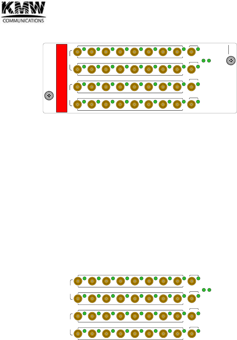
User Manual for POD Systems Revision: 0.7
© KMW USA Inc.
1818 E. Orangethrope Ave, Fullerton, CA 92831
Tel. +1 (714) 515-1100
www.kmwcomm.com
43
2.1.8 POD-H-DTM-8x8
Figure 2-30 POD-H-COM-8
2.1.8.1 Functions and features
- Receives downlink signals from up to 8 H-COM. After then, it combines and distributes them to up to 8 H-
HOM.
- Receives uplink signals from up to 8 H-HOM. After then, it combines and distributes them to up to 8 H-COM.
- Combines or distributes VHF, UHF signals
- To minimize negative effects by unused input/output ports such as the degradation of VSWR or isolation
between ports, the unused ports can be switched into 50 ohm termination by user
- Support Monitoring Port(DL path/UL Path)
- When any one sector or DAS system needs low power RU less than 4, H-COM can be connected to H-HOM-
L directly without H-DTM.
In this case, the attenuator in the common path of H-COM should add 15dB attenuation using web
based GUI to compensate the loss of H-DTM.
2.1.8.2 Specifications
- Frequency range: VHF, UHF, 600~2700MHz
- Maximum RF Power: -25dBm@DL, -15dBm@UL
- Size, weight, and power consumption : refer to Table 2-1
2.1.8.3 RF port and LED
Figure 2-31 POD-H-DTM-8x8 RF port and LED
RF Port
- DL IN #1 ~ #8
Receives downlink signal from H-COM, H-STM or H-OIM.
Connected to DL output port of H-COM, H-STM or H-OIM
Connector Type: SMB-L Female
- DL OUT #1 ~ #8
Combines inputted downlink signals from DL IN #1 to DL IN #8 and outputs to H-HOM
DTM-8x8
PWR
ALM
KMW
VHF
UHF
#1
#2
#3
#4
#5
#6
#7
#8
#1
#2
#3
#4
#5
#6
#7
#8
DL
MON
DL UL
VHF
UHF
#1
#2
#3
#4
#5
#6
#7
#8
#1
#2
#3
#4
#5
#6
#7
#8
UL
MON
IN OUT IN OUT
PWR
ALM
VHF
UHF
#1
#2
#3
#4
#5
#6
#7
#8
#1
#2
#3
#4
#5
#6
#7
#8
DL
MON
DL UL
VHF
UHF
#1
#2
#3
#4
#5
#6
#7
#8
#1
#2
#3
#4
#5
#6
#7
#8
UL
MON
IN OUT IN OUT
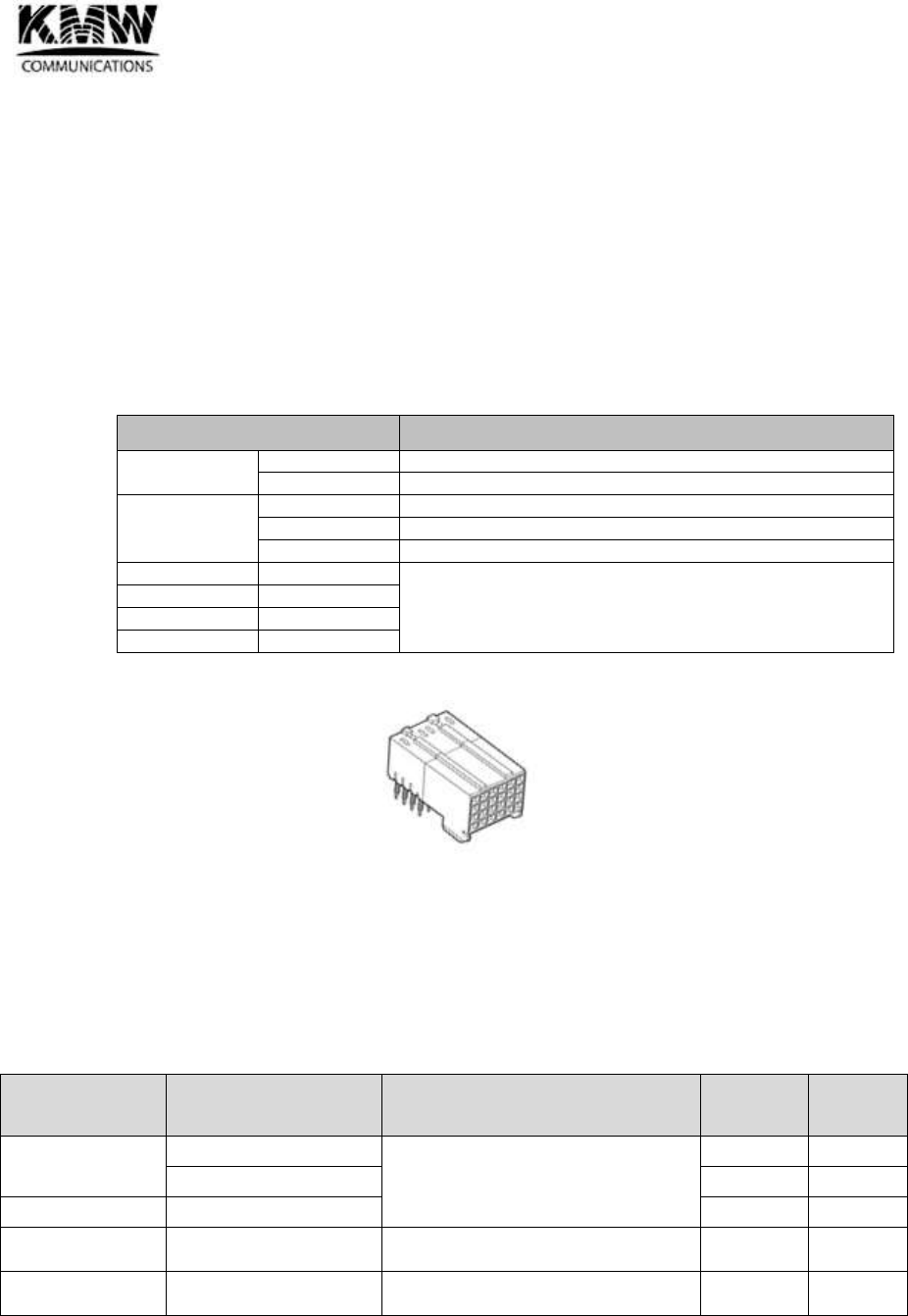
User Manual for POD Systems Revision: 0.7
© KMW USA Inc.
1818 E. Orangethrope Ave, Fullerton, CA 92831
Tel. +1 (714) 515-1100
www.kmwcomm.com
44
Connected to DL input port of H-HOM
Connector Type: SMB-L Female
- UL IN #1 ~ #8
Receives uplink signal from up to 8 H-HOM
Connected to UL output port of H-HOM
Connector Type: SMB-L Female
- UL OUT #1 ~ #8
Combines inputted uplink signals from UL IN #1 to UL IN #8 and outputs to H-COM, H-STM or H-OIM
Connected to UL input port of H-COM, H-STM or H-OIM
Connector Type: SMB-L Female
LED
Table 2-19 POD-H-DTM-8x8 LED Operation
Specifications
PWR
Solid Green
When power is on.
Off
When power is off.
ALM
Off
When POD-H-DTM-8x8 has no alarms.
Solid Yellow
When POD-H-DTM-8x8 has minor alarm.
Solid Red
When POD-H-DTM-8x8 has major alarm.
DL IN #1 ~ #8
Blink Green
At the cable connection guide, green led blinks to indicate which
RF ports should be connected to.
DL OUT #1 ~ #8
Blink Green
UL IN #1 ~ #8
Blink Green
UL OUT #1 ~ #8
Blink Green
2.1.8.4 Communication port
Figure 2-32 Communication Port
- This port provides communication path between H-DTM-8x8 and H-SCM through backboard of H-SRU.
- +24V DC is provided through this communication port from backboard of H-SRU.
- H-DTM-8x8 acquires ID information such as Rack ID, Sub rack ID and Slot ID through this communication
port. The IP address of H-DTM-8x8 is assigned automatically using the acquired ID information.
2.1.8.5 Alarms
Table 2-20 POD-H-DTM-8x8 - Alarms
Alarm Name
Description
Remedy
Alarm
Severity
LED
color
High Temperature
Temperature too high
Check environment
Major
Red
Temperature high
Minor
Yellow
Low Temperature
Temperature too low
Minor
Yellow
Link
Communication fail
Check pin of communication port/
assigned IP address
Major
Yellow
Downlink ALC
Activation
ALC activation
Check H-DTM downlink input level/
attenuator configuration
Warning
Yellow
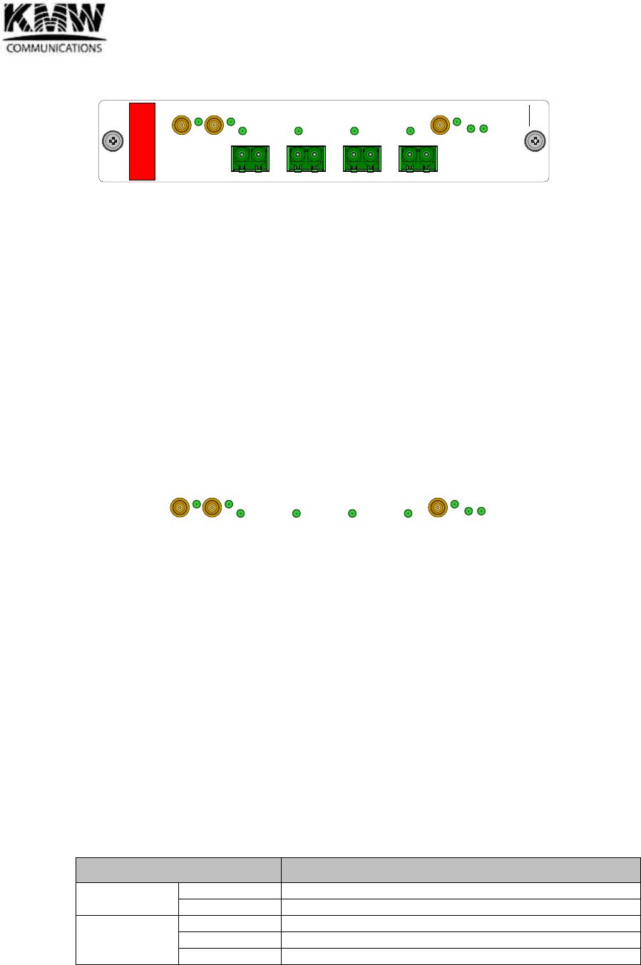
User Manual for POD Systems Revision: 0.7
© KMW USA Inc.
1818 E. Orangethrope Ave, Fullerton, CA 92831
Tel. +1 (714) 515-1100
www.kmwcomm.com
45
2.1.9 POD-H-HOM-L
Figure 2-33 POD-H-HOM-L
2.1.9.1 Functions and features
- Converts Downlink RF signal into optical signal and transfers to low power Remote Unit with less than 1W.
- Converts Uplink optic signal received from low power Remote Unit to RF signal and transfers to H-COM, H-
STM, or H-DTM.
- Compensates optic loss between HOM-L and low power Remote unit.
- For 2.6G TDD operation, TDD synchronization signal received from H-FEM-B is transferred to low power
Remote unit via H-HOM-L.
- Communicates with low power Remote unit by PLC modem.
2.1.9.2 Specifications
- Frequency range: VHF, UHF, 600~2700MHz
- Maximum RF Power: -9dBm@DL, 0dBm@UL
- Size, weight, and power consumption : refer to Table 2-1
2.1.9.3 RF port and LED
Figure 2-34 POD-H-HOM-L RF port and LED
RF Port
- DL IN
Receives downlink signal from H-COM, H-STM or H-DTM.
Connected to DL output port of H-COM, H-STM or H- DTM.
Connector Type: SMB-L Female
- UL OUT
Outputs uplink signal to H-COM, H-STM or H-DTM
Connected to UL input port of H-COM, H-STM or H-DTM
Connector Type: SMB-L Female
- T-SYNC IN
Receives TDD synchronization signal from H-FEM-B.
Connected to T-SYNC of H-FEM-B.
Connector Type: SMB-L Female
LED
Table 2-21 POD-H-HOM-L LED Operation
Specifications
PWR
Solid Green
When power is on.
Off
When power is off.
ALM
Off
When POD-H-HOM-L has no alarms.
Solid Yellow
When POD-H-HOM-L has minor alarm.
Solid Red
When POD-H-HOM-L has major alarm.
HOM-L
PWR
ALM
UL Out
DL In
T_Sync
UL
UL
UL
UL
KMW
# 1
# 2
# 3
# 4
DL
DL
DL
DL
PWR
ALM
UL Out
DL In
T_Sync
UL
UL
UL
UL
DL
DL
DL
DL
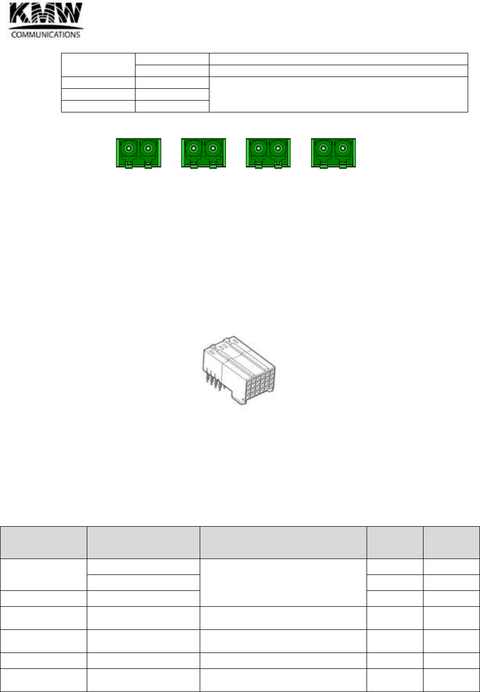
User Manual for POD Systems Revision: 0.7
© KMW USA Inc.
1818 E. Orangethrope Ave, Fullerton, CA 92831
Tel. +1 (714) 515-1100
www.kmwcomm.com
46
UL #1 ~ #4
Off
When PD fails.
Solid Yellow
When PD is Normal.
DL IN
Blink Green
At the cable connection guide, green led blinks to indicate which
RF ports should be connected to.
UL OUT
Blink Green
T_Sync
Blink Green
2.1.9.4 Optic port
Figure 2-35 optic port
LD #1 ~ #4
- Each optic port is connected to one low power Remote Unit.
- Transfers downlink optic signal to low power Remote Unit.
- Connector Type: LC APC Female
PD #1 ~ #4
- Each optic port is connected to low power Remote Unit.
- Receives Uplink optic signal from low power Remote Unit.
- Connector Type: LC APC Female
2.1.9.5 Communication port
Figure 2-36 Communication Port
- This port provides communication path between H-HOM-L and H-SCM through backboard of H-SRU.
- +24V DC is provided through this communication port from backboard of H-SRU.
- H-HOM-L acquires ID information such as Rack ID, Sub rack ID and Slot ID through this communication port.
The IP address of H-HOM-L is assigned automatically using the acquired ID information.
2.1.9.6 Alarms
Table 2-22 POD-H-HOM-L - Alarms
Alarm Name
Description
Remedy
Alarm
Severity
LED
color
High Temperature
Temperature too high
Check environment
Major
Red
Temperature high
Minor
Yellow
Low Temperature
Temperature too low
Minor
Yellow
Link
Communication fail
Check pin of communication port/
assigned IP address
Major
Yellow
DL Optic Fail
Downlink LD fail
Check if optic LD fail alarm occurs again
after reset.
Major
Yellow
UL Optic Fail
Uplink PD fail
Check optic cable connection with RU
Major
Yellow
UL Optic Loss
Exceed permitted optic
loss
Check optic cable connection with RU /
clean Optic connector and port
Minor
Yellow
# 1
# 2
# 3
# 4

User Manual for POD Systems Revision: 0.7
© KMW USA Inc.
1818 E. Orangethrope Ave, Fullerton, CA 92831
Tel. +1 (714) 515-1100
www.kmwcomm.com
47
Alarm Name
Description
Remedy
Alarm
Severity
LED
color
RU Comm. Fail
RU Communication Fail
Check optic cable connection
Minor
Yellow
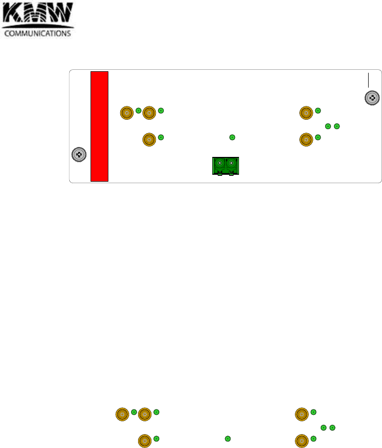
User Manual for POD Systems Revision: 0.7
© KMW USA Inc.
1818 E. Orangethrope Ave, Fullerton, CA 92831
Tel. +1 (714) 515-1100
www.kmwcomm.com
48
2.1.10 POD-H-HOM-H
Figure 2-37 POD-H-HOM-H
2.1.10.1 Functions and features
- Converts Downlink RF signal into optical signal and transfers to high power Remote Unit with more than
20W.
- Converts Uplink optic signal received from high power Remote Unit to RF signal and transfers to H-COM, H-
STM, or H-DTM.
- Compensates optic loss between HOM-L and high power Remote unit.
- For 2.6G TDD operation, TDD synchronization signal received from H-FEM-B is transferred to high power
Remote unit via H-HOM-L.
- Communicates with high power Remote unit by PLC modem.
2.1.10.2 Specifications
- Frequency range: VHF, UHF, 600~2700MHz
- Maximum RF Power: -9dBm@DL, 0dBm@UL
- Size, weight, and power consumption : refer to Table 2-1
2.1.10.3 RF port and LED
Figure 2-38 POD-H-HOM-H RF port and LED
RF Port
- DL 1/DL 2
Receives downlink signal from H-COM, H-STM or H-DTM.
Connected to DL output port of H-COM, H-STM or H- DTM.
Connector Type: SMB-L Female
- UL 1/UL 2
Outputs uplink signal to H-COM, H-STM or H-DTM
Connected to UL input port of H-COM, H-STM or H-DTM
Connector Type: SMB-L Female
- T-SYNC IN
Receives TDD synchronization signal from H-FEM-B.
Connected to T-SYNC of H-FEM-B.
Connector Type: SMB-L Female
LED
HOM-H
PWR
ALM
KMW
UL1 UL2
DL1 DL2
T_Sync
DL/UL
#1
PWR
ALM
UL1 UL2
DL1 DL2
T_Sync
DL/UL
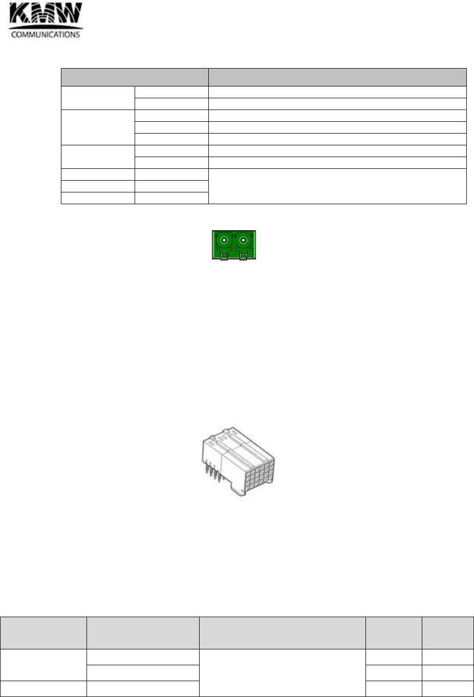
User Manual for POD Systems Revision: 0.7
© KMW USA Inc.
1818 E. Orangethrope Ave, Fullerton, CA 92831
Tel. +1 (714) 515-1100
www.kmwcomm.com
49
Table 2-23 POD-H-HOM-L LED Operation
Specifications
PWR
Solid Green
When power is on.
Off
When power is off.
ALM
Off
When POD-H-HOM-H has no alarms.
Solid Yellow
When POD-H-HOM-H has minor alarm.
Solid Red
When POD-H-HOM-H has major alarm.
DL/UL
Off
When PD fails.
Solid Yellow
When PD is Normal.
DL 1/DL 2
Blink Green
At the cable connection guide, green led blinks to indicate which
RF ports should be connected to.
UL 1/UL 2
Blink Green
T_Sync
Blink Green
2.1.10.4 Optic port
Figure 2-39 optic port
LD
- Connected to high power Remote Unit.
- Transfers downlink optic signal to high power Remote Unit.
- Connector Type: LC APC Female
PD
- Connected to high power Remote Unit.
- Receives Uplink optic signal from high power Remote Unit.
- Connector Type: LC APC Female
2.1.10.5 Communication port
Figure 2-40 Communication Port
- This port provides communication path between H-HOM-H and H-SCM through backboard of H-SRU.
- +24V DC is provided through this communication port from backboard of H-SRU.
- H-HOM-H acquires ID information such as Rack ID, Sub rack ID and Slot ID through this communication port.
The IP address of H-HOM-H is assigned automatically using the acquired ID information.
2.1.10.6 Alarms
Table 2-24 POD-H-HOM-H - Alarms
Alarm Name
Description
Remedy
Alarm
Severity
LED
color
High Temperature
Temperature too high
Check environment
Major
Red
Temperature high
Minor
Yellow
Low Temperature
Temperature too low
Minor
Yellow
#1

User Manual for POD Systems Revision: 0.7
© KMW USA Inc.
1818 E. Orangethrope Ave, Fullerton, CA 92831
Tel. +1 (714) 515-1100
www.kmwcomm.com
50
Link
Communication fail
Check pin of communication port/
assigned IP address
Major
Yellow
DL Optic Fail
Downlink LD fail
Check if optic LD fail alarm occurs again
after reset.
Major
Yellow
UL Optic Fail
Uplink PD fail
Check optic cable connection with RU
Major
Yellow
UL Optic Loss
Exceed permitted optic
loss
Check optic cable connection with RU /
clean Optic connector and port
Minor
Yellow
RU Comm. Fail
RU Communication Fail
Check optic cable connection
Minor
Yellow
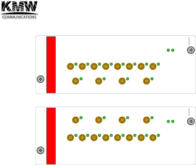
User Manual for POD Systems Revision: 0.7
© KMW USA Inc.
1818 E. Orangethrope Ave, Fullerton, CA 92831
Tel. +1 (714) 515-1100
www.kmwcomm.com
51
2.1.11 POD-H-STM-8x4
Figure 2-41 POD-H-STM-8x4-DL
Figure 2-42 POD-H-STM-8x4-UL
2.1.11.1 Functions and features
- Programmable sectorization can be supported by using H-STM-8x4.
- Based on programmed sector definition, DL output signals received from H-FEM are combined by each
sector and transferred to H-DTM, or H-HOM.
- Based on programmed sector definition, received UL signals from H-DTM, or H-HOM are distributed and
transferred to H-FEM.
- For each sector, controls Power Ratio for multiple H-FEM with same frequency band to share DL output
power at Remote Unit
- ALC function for DL/UL Path
- To minimize negative effects by unused input/output ports such as the degradation of VSWR or isolation
between ports, the unused ports can be switched into 50 ohm termination by user.
- When any one sector consists of remote unit less than 4, H-STM-8x4 can be connected to H-HOM-L directly
without H-DTM.
In this case, the attenuator in the common path of H-STM-8x8 should add 15dB attenuation using web
based GUI to compensate the loss of H-DTM.
2.1.11.2 Specifications
- Frequency range: 600~2700MHz
- Maximum RF Power: -10dBm@DL, 25dBm@UL
- Size, weight, and power consumption : refer to Table 2-1
STM-8x4 DL
PWR
KMW
#1
#2
#3
#4
#1
#2
#3
#4
#5
#6
#7
#8
ALM
STM-8x4 UL
PWR
KMW
#1
#2
#3
#4
#1
#2
#3
#4
#5
#6
#7
#8
ALM
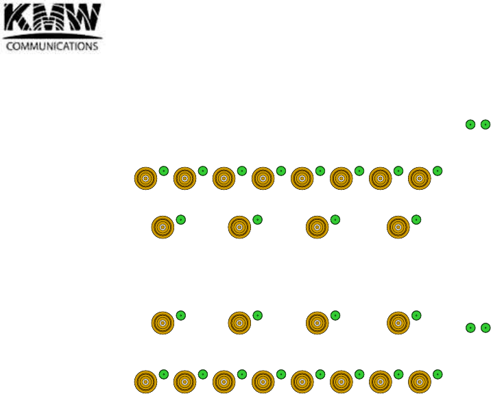
User Manual for POD Systems Revision: 0.7
© KMW USA Inc.
1818 E. Orangethrope Ave, Fullerton, CA 92831
Tel. +1 (714) 515-1100
www.kmwcomm.com
52
2.1.11.3 RF port and LED
Figure 2-43 POD-H-STM-8x4-DL RF port and LED
Figure 2-44 POD-H-STM-8x4-UL RF port and LED
RF port
- POD-H-STM-8x4-DL
DL IN #1 ~ #8
Receives downlink signal from up to 8 H-FEM
Connected to DL output port of H-FEM
Connector Type: SMB-L Female
DL OUT #1 ~ #4
Combines inputted downlink signals and outputs to H-DTM or H-HOM by each sector
Connected to DL input port of H-DTM, or H-HOM for each sector
Connector Type: SMB-L Female
- POD-H-STM-8x4-UL
UL IN #1 ~ #8
Receives uplink signals from H-DTM, or H-HOM for each sector
Connected to UL output port of H-DTM, or H-HOM for each sector
Connector Type: SMB-L Female
UL OUT #1 ~ #4
Distributes uplink signals inputted from UL IN #1~#8 port by each sector and outputs to H-
FEM
Connected to UL input port of H-FEM
Connector Type: SMB-L Female
PWR
#1
#2
#3
#4
#1
#2
#3
#4
#5
#6
#7
#8
ALM
PWR
#1
#2
#3
#4
#1
#2
#3
#4
#5
#6
#7
#8
ALM

User Manual for POD Systems Revision: 0.7
© KMW USA Inc.
1818 E. Orangethrope Ave, Fullerton, CA 92831
Tel. +1 (714) 515-1100
www.kmwcomm.com
53
LED
Table 2-25 POD-H-STM-8x4 LED Operation
Specifications
PWR
Solid Green
When power is on.
Off
When power is off.
ALM
Off
When POD-H-STM-8x4-DL (UL) has no alarms.
Solid Yellow
When POD-H-STM-8x4-DL (UL) has minor alarm.
Solid Red
When POD-H-STM-8x4-DL (UL) has major alarm.
DL IN #1 ~ #8
Blink Green
At the cable connection guide, green led blinks to indicate which
RF ports should be connected to.
DL OUT #1 ~ #4
Blink Green
UL IN #1 ~ #8
Blink Green
UL OUT #1 ~ #4
Blink Green
2.1.11.4 Communication port
Figure 2-45 Communication Port
- This port provides communication path between H-STM and H-SCM through backboard of H-SRU.
- +24V DC is provided through this communication port from backboard of H-SRU.
- H-STM acquires ID information such as Rack ID, Sub rack ID and Slot ID through this communication port.
The IP address of H-STM is assigned automatically using the acquired ID information.
2.1.11.5 Alarms
Table 2-26 POD-H-STM-8x8 - Alarms
Alarm Name
Description
Remedy
Alarm
Severity
LED
color
High Temperature
Temperature too high
Check environment
Major
Red
Temperature high
Minor
Yellow
Low Temperature
Temperature too low
Minor
Yellow
Link
Communication fail
Check pin of communication port/
assigned IP address
Major
Yellow
Downlink ALC
Activation
ALC activation
Check H-STM downlink input level/
attenuator configuration
Warning
Yellow
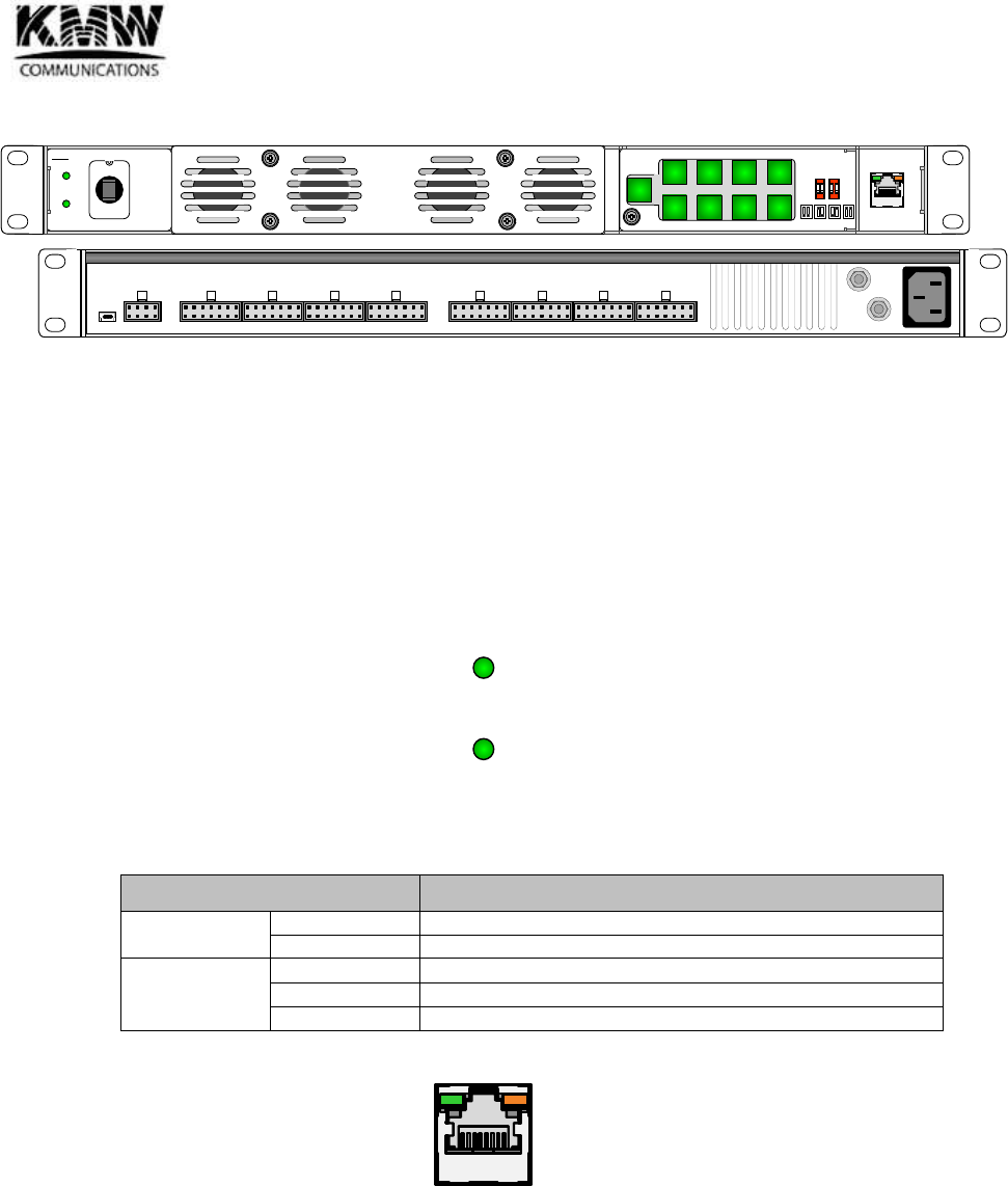
User Manual for POD Systems Revision: 0.7
© KMW USA Inc.
1818 E. Orangethrope Ave, Fullerton, CA 92831
Tel. +1 (714) 515-1100
www.kmwcomm.com
54
2.1.12 POD-H-PSU-x
Figure 2-46 POD-H-PSU-x
2.1.12.1 Functions and features
- Distributes +24Vdc to DMCU and up to 8 H-SRUs
- Turn on or off each DC output individually in a local or remote site
- Set Rack ID
2.1.12.2 Specifications
- AC input Range: AC 100~240V (47~63Hz)
- Size, weight, and power consumption : refer to Table 2-1
2.1.12.3 LED
Figure 2-47 POD-H-PSU-x LED
Table 2-27 POD-H-PSU-x LED Operation
Specifications
PWR
Solid Green
When power is on.
Off
When power is off.
ALM
Off
When POD-H-PSU-x has no alarms.
Solid Yellow
When POD-H-PSU-x has minor alarm.
Solid Red
When POD-H-PSU-x has major alarm.
2.1.12.4 Ethernet Port
Figure 2-48 Ethernet Port
DMCU port
- Connected to H-DMCU so that H-DMCU can monitor and control H-PSU
2.1.12.5 AC input on/off Switch & DC output on/off switch
DMCU
HPSU
Power
Alarm
#1 #2 #3 #4
#5 #6 #7 #8
DMCU
#1 #2 #3 #4
1 2 1 2
Group Rack
KMW
#1 #2 #3 #4 #5 #6 #7 #8
DMCU HSRU
Power
Alarm
DMCU
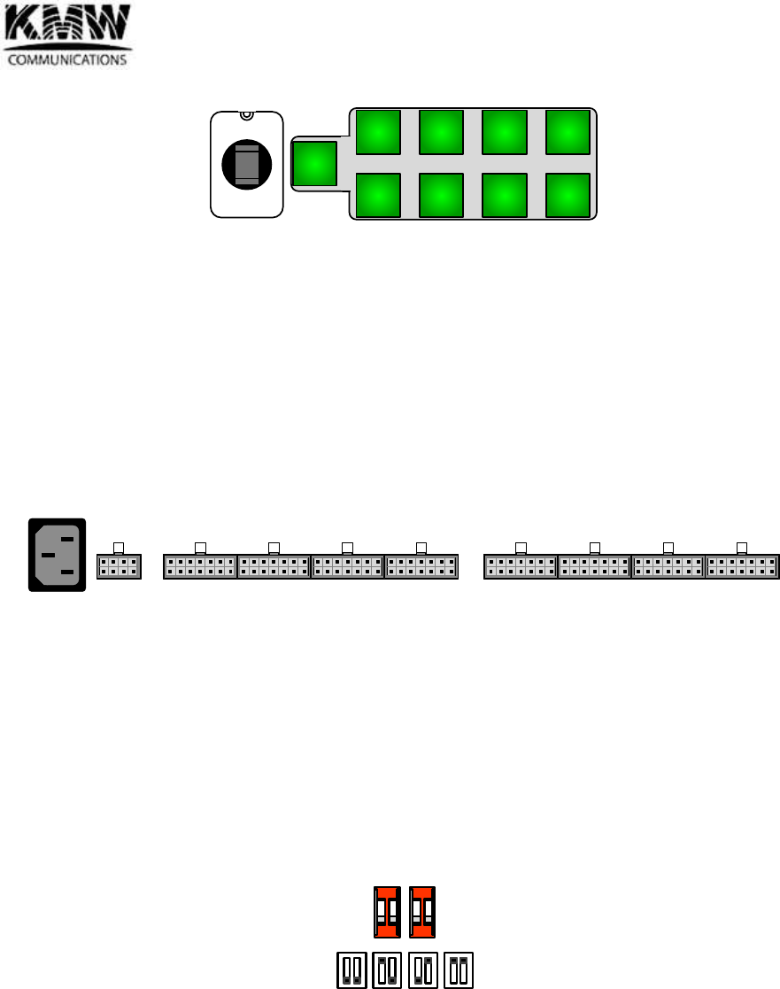
User Manual for POD Systems Revision: 0.7
© KMW USA Inc.
1818 E. Orangethrope Ave, Fullerton, CA 92831
Tel. +1 (714) 515-1100
www.kmwcomm.com
55
Figure 2-49 AC input on/off Switch & DC output on/off switch
AC input on/off switch
- Be able to turn AC input on (off) manually by using AC input on/off switch
DC output on/off switch
- Be able to turn each DC output on (off) separately
- Toggle type
When you press DC output on/off switch, the LED light of DC output on/off switch and 24V DC output
turn on, and when you press it again, LED light and 24V DC output turn off.
- DC output on/off switch can be turned on (off) in local and remote site
2.1.12.6 AC input port & DC output port
Figure 2-50 AC input port & DC output port
AC input port
- Use 3 wire AC code (Line, Neutral, GND)
DC output port
- One DC output port for H-DMCU
DC output connector contains +24V DC, Rack ID, and insert pin.
- Eight DC output port for H-SRU
Each DC output connector contains +24V DC, Rack ID, and insert pin.
2.1.12.7 Rack ID
Figure 2-51 Rack ID
Group is not used
Rack ID
- Rack ID can be set from 1 to 4.
- One H-DMCU can support up to 4 racks, and one H-DMCU needs maximum 4 H-PSU because one H-PSU can
supply 24V DC power to only one rack that can be composed of up to 8 H-SRUs and one DMCU.
- H-DMCU and each H-SCM in H-SRU can identify its own rack ID through the cable connection with H-PSU.
HPSU
#1 #2 #3 #4
#5 #6 #7 #8
#1 #2 #3 #4 #5 #6 #7 #8
DMCU HSRU
#1 #2 #3 #4
1 2 1 2
Group Rack
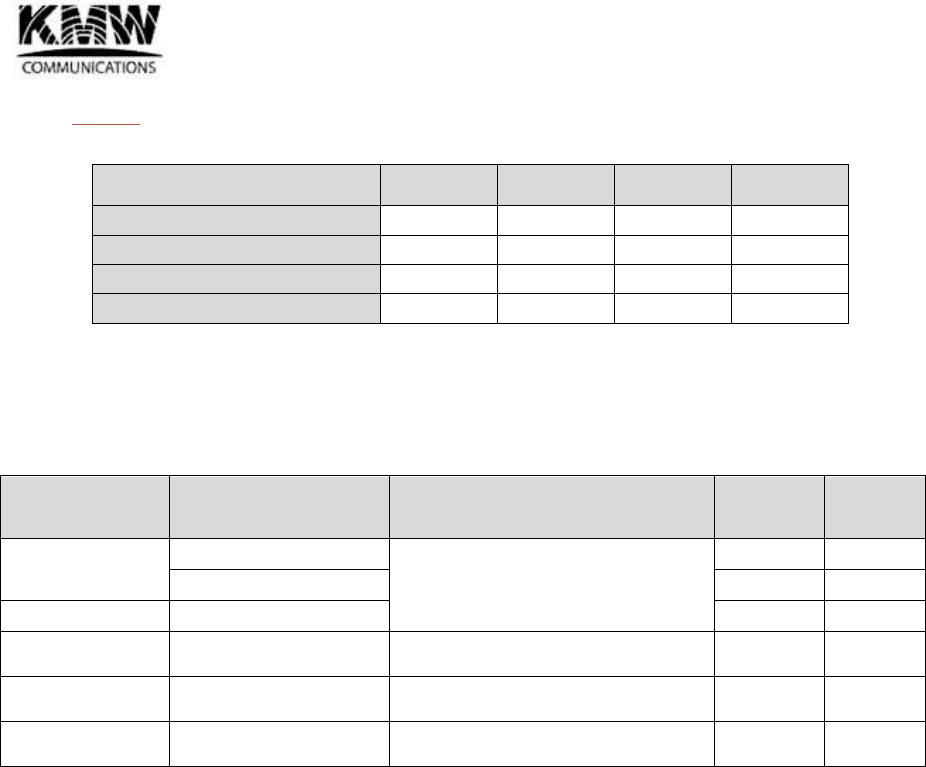
User Manual for POD Systems Revision: 0.7
© KMW USA Inc.
1818 E. Orangethrope Ave, Fullerton, CA 92831
Tel. +1 (714) 515-1100
www.kmwcomm.com
56
- CAUTION) The rack ID connected to H-DMCU must be set as 1.
Table 2-28 Rack ID
DIP Switch Setting
Group 1
Group 2
Rack 1
Rack 2
Rack ID #1
X
X
OFF
OFF
Rack ID #2
X
X
ON
OFF
Rack ID #3
X
X
OFF
ON
Rack ID #4
X
X
ON
ON
2.1.12.8 Ground port
- Refer to section 3.2.2
2.1.12.9 Alarms
Table 2-29 POD-H-PSU - Alarms
Alarm Name
Description
Remedy
Alarm
Severity
LED
color
High Temperature
Temperature too high
Check environment
Major
Red
Temperature high
Minor
Yellow
Low Temperature
Temperature too low
Minor
Yellow
Voltage
High Voltage
Check if High voltage alarm occurs again
after reset.
Major
Red
Current
High Current
Check if current alarm occurs again after
reset.
Major
Red
Low Voltage
Low Voltage
Check if low voltage alarm occurs again
after reset.
Major
Yellow
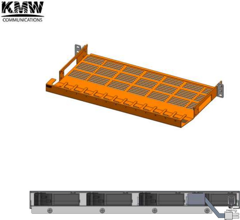
User Manual for POD Systems Revision: 0.7
© KMW USA Inc.
1818 E. Orangethrope Ave, Fullerton, CA 92831
Tel. +1 (714) 515-1100
www.kmwcomm.com
57
2.1.13 POD-H-CDU
Figure 2-52 POD-H-CDU
2.1.13.1 Functions and features
- Provides cable routing space when RF, optic, DC power, and Ethernet cables are connected between the
modules or units in POD DAS system.
- Has good space efficiency since H-FAU can be installed behind H-CDU
2.1.14 POD-H-FAU
Figure 2-53 POD-H-FAU
2.1.14.1 Functions and features
- Installed right above the H-SRU for dissipating heat comes from the modules installed in POD-H-SRU.
- Good space efficiency since H-FAU can be installed behind H-CDU
- DC Power is provided from FAN port located in the back side of H-SRU
- FAN speed control and FAN on/off is controlled automatically by H-SCM based on the temperature of
modules installed in H-SRU.
- FAN fail alarm is monitored by H-SCM.
2.1.14.2 The rules for installing FAN unit
- When the number of module installed in a POD-H-SRU is less than 5, it doesn’t need the installation of H-
FAU.
- When the number of module installed in a POD-H-SRU is more than 6, It needs the installation of POD-H-
FAU.
We strongly recommend that each module should be installed every other slot in a POD-H-SRU.
- When POD-H-SRUs more than 2 are stacked in one rack, one POD-H-FAU per 2 POD-H-SRU should be
installed regardless of the number of module installed in one POD-H-SRU.
We strongly recommend that each module should be installed with sufficient gap as far as possible
when the modules in a POD-H-SRU are not fully installed.
2.1.14.3 Port
- H-FAU must be connected with FAN port which is located in the back of H-SRU (refer to Figure 2-9) by
provided signal cable.

User Manual for POD Systems Revision: 0.7
© KMW USA Inc.
1818 E. Orangethrope Ave, Fullerton, CA 92831
Tel. +1 (714) 515-1100
www.kmwcomm.com
58
- Control signal for FAN speed control, DC power and FAN alarm signal are transferred between H-FAU and
H-SCM through this signal cable.
2.1.14.4 Alarms
Table 2-30 POD-H-FAU - Alarms
Alarm Name
Description
Remedy
Alarm
Severity
LED
color
FAN
FAN fail
Replace FAN
Minor
Yellow
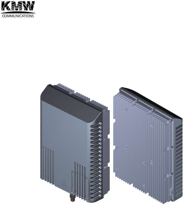
User Manual for POD Systems Revision: 0.7
© KMW USA Inc.
1818 E. Orangethrope Ave, Fullerton, CA 92831
Tel. +1 (714) 515-1100
www.kmwcomm.com
59
2.2 Remote Unit
RU (Remote Unit) provides wireless service coverage to users by transmitting downlink signal through the
service antenna.
Remote units which is supported by KMW are as below.
- 7/5/3 band RU for commercial band service (POD-R-7S8CPAWB-2730-AC/DC)
- PS700/800 RU for public safety band service (POD-R-P78-27-AC/DC)
- High power RU with 20/40W output power (POD-R-4346-AC/DC)
2.2.1 7/5/3 band RU for commercial band service (POD-R-7S8CPAWB-2730-AC/DC)
Figure 2-54 Remote Unit – 7/5/3 band
2.2.1.1 Functions and features
- Supported frequency band
3_band RU: SMR800, PCS, and 2.6G TDD
5_band RU: 700M, 850M, PCS, AWS, and WCS
7_band RU: 700M, SMR800+850M, PCS, AWS, WCS, and 2.6G TDD
- VSWR measurement function for checking VSWR of the connected service antenna
- Built-in Test tone generator in order to check uplink path verification
- Increase scalability by supporting expansion RU
Expansion RU is connected with main RU through AUX DL/UL port by using RF cable
Expansion RU can be added, when it needs additional frequency band other than frequency bands
being used in main RU, or additional filter attenuation in the frequency band being used in main RU. In
the latter case, the frequency band which needs additional filter attenuation must be off in main RU
and replaced by the frequency band with strengthened filter attenuation in expansion RU.
2.2.1.2 Specifications
Common Specifications
- Operating Temperature: -40~55C

User Manual for POD Systems Revision: 0.7
© KMW USA Inc.
1818 E. Orangethrope Ave, Fullerton, CA 92831
Tel. +1 (714) 515-1100
www.kmwcomm.com
60
- Input Power
AC type: 110V, 50-60 Hz
DC Type: -48V
- IP rating: IP65
- Cooling method: convection cooling
- Dimension: (WxHxD) 13 x 17.3 x 4.7 in (330 x 440 x 120mm)
- Weight: 37.5 lbs (17kg)
-
700M, SMR800 + 850M
Table 2-31 3/5/7 band RU - 700M, SMR800 + 850M Specifications
700M
SMR800+850M
Lower ABC
Upper C
Frequency Band
Downlink
728.0M - 746.0M
746.0M - 756.0M
862.0M - 894.0M
Uplink
698.0M - 716.0M
777.0M - 787.0M
817.0M - 849.0M
Bandwidth
18.0 MHz
10.0 MHz
32 MHz
Mean Gain
Downlink
36 ± 1.0 dB
36 ± 1.0 dB
Uplink
37 ± 1.0 dB
37±1.0 dB
37 ± 1.0 dB
Maximum Gain
Downlink
42 dB
Uplink
37 dB
Ripple(p-p)
Downlink
2.5 dB
2.0 dB
Uplink
2.5 dB
4.0 dB @Full band
2.5dB@ 777~786M
2.0 dB
Maximum downlink output power
27 dBm
27 dBm
Uplink Noise Figure @center freq.
4.00 dB
4.00 dB
4.00 dB
VSWR
< 1:1.7
Delay
< 5.00 us
EVM
< 5.0 % @E-TM 3.1
Operating band unwanted emissions
Meet FCC, 3GPP WCDMA/LTE Repeater Spec., 3GPP2 CDMA spec.
Out of band emission
Meet FCC, 3GPP WCDMA/LTE Repeater Spec., 3GPP2 CDMA spec.
PCS, AWS
Table 2-32 3/5/7 band RU – PCS, AWS Specifications
PCS
AWS
Frequency Band
Downlink
1930.0M - 1995.0M
2110.0M - 2180.0M
Uplink
1850.0M-1915.0M
1710.0M-1780.0M
Bandwidth
65.0 MHz
70.0 MHz
Mean Gain
Downlink
39 ± 1.0 dB
39 ± 1.0 dB
Uplink
40 ± 1.0 dB
40 ± 1.0 dB
Maximum Gain
Downlink
45 dB
Uplink
40 dB
Ripple(p-p)
Downlink
3.5 dB@ Full band
2.5dB (excluding band edge)
2.0 dB
Uplink
3.5 dB
2.5dB (excluding band edge)
2.0 dB
Maximum downlink output power
30 dBm
30 dBm
Uplink Noise Figure @center freq.
4.00 dB
4.00 dB
User Manual for POD Systems Revision: 0.7
© KMW USA Inc.
1818 E. Orangethrope Ave, Fullerton, CA 92831
Tel. +1 (714) 515-1100
www.kmwcomm.com
61
PCS
AWS
VSWR
< 1:1.7
Delay
< 5.00 us
EVM
< 5.0 % @E-TM 3.1
Operating band unwanted emissions
Meet FCC, 3GPP WCDMA/LTE Repeater Spec., 3GPP2 CDMA spec.
Out of band emission
Meet FCC, 3GPP WCDMA/LTE Repeater Spec., 3GPP2 CDMA spec.
WCS, 2.65G
Table 2-33 3/5/7 band RU – WCS, 2.6G Specifications
WCS
2.6G
Frequency Band
Downlink
2350.0M - 2360.0M
2496.0M - 2690.0M
Uplink
2305.0M-2315.0M
2496.0M-2690.0M
Bandwidth
10.0 MHz
194.0 MHz
Mean Gain
Downlink
39 ± 1.0 dB
39 ± 1.0 dB
Uplink
40 ± 1.0 dB
40 ± 1.0 dB
Maximum Gain
Downlink
45 dB
Uplink
40 dB
Ripple(p-p)
Downlink
2.5 dB
3.5 dB
Uplink
1.75 dB
3.5 dB
Maximum downlink output power
30 dBm
30 dBm
Uplink Noise Figure @center freq.
5.00 dB
4.00 dB
VSWR
< 1:1.7
Delay
< 5.00 us
< 2.00 us
EVM
< 5.0 % @E-TM 3.1
Operating band unwanted emissions
Meet FCC, 3GPP WCDMA/LTE Repeater Spec.
Out of band emission
Meet FCC, 3GPP WCDMA/LTE Repeater Spec.
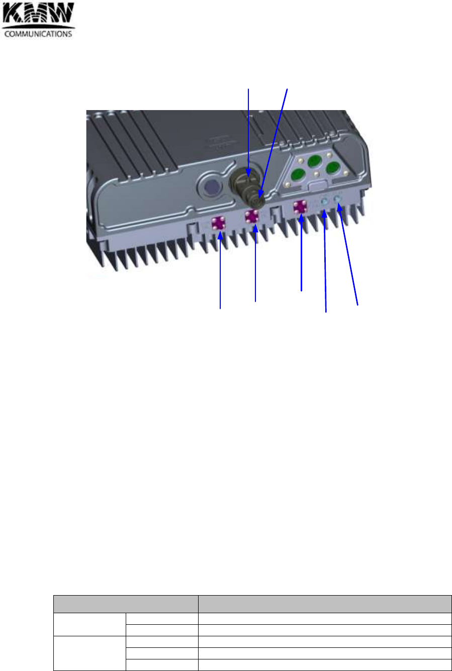
User Manual for POD Systems Revision: 0.7
© KMW USA Inc.
1818 E. Orangethrope Ave, Fullerton, CA 92831
Tel. +1 (714) 515-1100
www.kmwcomm.com
62
2.2.1.3 RF ports and LED
Figure 2-55 Remote Unit External Interfaces
RF port
- ANT port
Connected to Service antenna
Mini DIN, female type
- CPL port
Can be connected to spectrum analyzer to monitor downlink spectrum without interrupting wireless
service
SMA female type
- AUX UL & DL
Connected to expansion remote unit
QMA female type
- TDD sync port
Provides TDD sync signal which can be used to synchronize with TDD signal measuring equipment such
as spectrum analyzer.
QMA female type
LED
Table 2-34 7/5/3 band RU LED Operation
Specifications
PWR
Solid Green
When power is on.
Off
When power is off.
ALM
Off
When 7/5/3 band RU has no alarms.
Solid Yellow
When 7/5/3 band RU has minor alarm.
Solid Red
When 7/5/3 band RU has major alarm.
AUX UL
Port
AUX DL
Port
TDD Sync
Port ALM
LED
PWR
LED
ANT Port
CPL Port
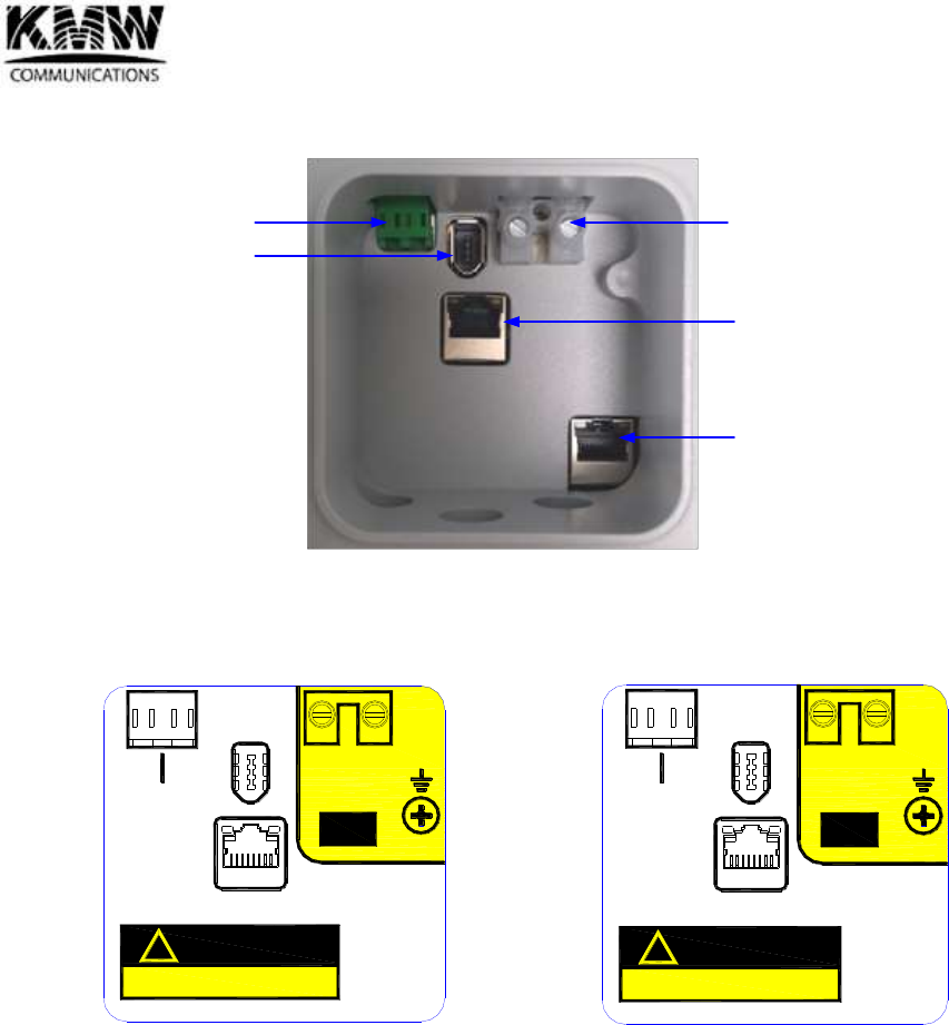
User Manual for POD Systems Revision: 0.7
© KMW USA Inc.
1818 E. Orangethrope Ave, Fullerton, CA 92831
Tel. +1 (714) 515-1100
www.kmwcomm.com
63
2.2.1.4 Debug Window
Figure 2-56 Debug Window
User can know the name for each port of RU by attached sticker on the cover of debug window when user opens
debug window. User can verify whether RU is AC or DC type, and RU is main RU or expansion RU.
Main RU - AC type
Main RU - DC type
Optic Port AC or DC Power
input Port
Serial Port
Ethernet Port #1
Ethernet Port #2
GUI / EXT
DEBUG
UL DL
(OPTIC)
AC
(L) AC
(N)
AC
AC ONLY
CAUTION
!
DEBUG
GUI / EXT
UL DL
(OPTIC)
RTN
-48V
DC
DC ONLY
CAUTION
!
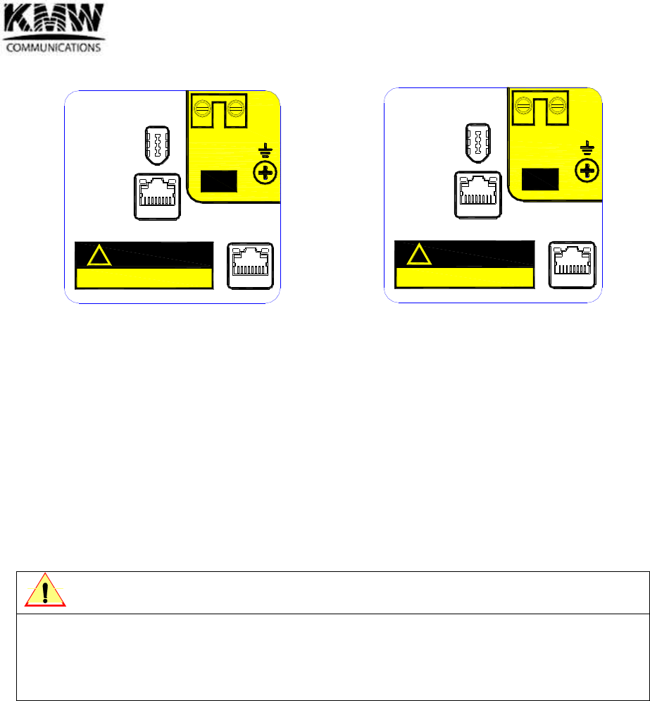
User Manual for POD Systems Revision: 0.7
© KMW USA Inc.
1818 E. Orangethrope Ave, Fullerton, CA 92831
Tel. +1 (714) 515-1100
www.kmwcomm.com
64
Expansion RU - AC type
Expansion RU - DC type
Figure 2-57 Port name for each RU type
Optic port
- Connected to Head-end
- Expansion RU doesn’t need optic port because it is connected to main RU through RF cable.
- LC/APC Female type
- Wavelength: 1310nm for downlink, 1550nm for uplink
Serial port (DEBUG): Used for internal debug
AC or DC power input port
- AC or DC power source is provided into Remote unit through this port.
110V AC, 50~60Hz or DC -48V
CAUTION
Make sure whether remote unit is AC or DC type before connecting input power to AC or DC input port
Because AC and DC input port uses same connector, user might be confused, so that the wrong
connection of input power might cause severe damage of remote unit.
User can check easily whether remote unit is AC or DC type by checking the picture of sticker attached
to the debug window cover when you open it. (refer to Figure 2-57)
Ethernet Port
- Ethernet Port #1
Used as GUI Port to access web-based GUI when expansion RU is not connected
Used for connecting to expansion RU when expansion RU is connected to main RU.
Use GUI port in expansion RU to access web-based GUI when expansion RU is connected
- Ethernet Port #2
Used as GUI Port to access web-based GUI for only expansion RU
GUI
AC
AC ONLY
CAUTION
!
AC
(L) AC
(N)
EXT
DEBUG
GUI
DC
DC ONLY
CAUTION
!
RTN
-48V
EXT
DEBUG

User Manual for POD Systems Revision: 0.7
© KMW USA Inc.
1818 E. Orangethrope Ave, Fullerton, CA 92831
Tel. +1 (714) 515-1100
www.kmwcomm.com
65
2.2.1.5 Alarms
Table 2-35 3/5/7 band RU – Alarms
Alarm Name
Description
Remedy
Alarm
Severity
LED
color
High Temperature
Temperature too high
Check environment
Major
Red
Temperature high
Minor
Yellow
Low Temperature
Temperature too low
Minor
Yellow
Downlink High
Output Power
RF signal too high
Check Head-end downlink input level/
attenuator configuration/ALC status
Major
Red
RF signal high
Major
Yellow
Uplink High Input
Power
RF signal too high
Check RU uplink input level/ attenuator
configuration/ ALC status
Major
Red
RF signal high
Major
Yellow
Downlink Low
Output Power
RF signal too low
Check Head-end downlink input level/
attenuator configuration/ RF cabling
Minor
Yellow
Link
Communication fail
Check cable connection
Major
Yellow
Freeze
The final stage of
Shutdown process
Check if shutdown process is going again
after reset
Major
Red
Downlink ALC
Activation
ALC activation
Check Head-end downlink input level/
attenuator configuration
Warning
Yellow
Uplink PLL Unlock
Uplink PLL unlock
Check if uplink PLL is still in unlocked
status after resetting PLL frequency
Minor
Yellow
VSWR
Bad RF cable/mismatched
service antenna
Check cable between RU and service
antenna, VSWR of service antenna
Major
Yellow
Optic LD Fail
Uplink LD fail
Check if optic LD fail alarm occurs again
after reset.
Major
Yellow
Optic PD Fail
Downlink PD fail
Check optic cable connection with H-
HOM
Major
Yellow
Optic Loss
Excess permitted optic loss
Check optic cable connection with H-
HOM / clean Optic connector and port
Minor
Yellow
High current
Power supply load too high
Check if current alarm occurs again after
reset.
Major
Red
Sync fail
No TDD sync signal is
acquired
Check optic cable connection with H-
HOM and 2.6G downlink input signal
Major
Yellow
2.2.1.6 Grounding
- Refer to section 3.3.2
User Manual for POD Systems Revision: 0.7
© KMW USA Inc.
1818 E. Orangethrope Ave, Fullerton, CA 92831
Tel. +1 (714) 515-1100
www.kmwcomm.com
66
2.2.2 PS700/800 RU for public safety 700/800 frequency band service (POD-R-P78-27-AC/DC)
Figure 2-58 Remote Unit – PS700/800
2.2.2.1 Functions and features
- Supported frequency band: Public Safety 700M & 800M
- VSWR measurement function for checking VSWR of the connected service antenna
- Built-in Test tone generator in order to check uplink path verification
- Increase scalability by supporting expansion RU
Connected between expansion RU and main RU through AUX DL/UL port by using RF cable
Expansion RU can be added, when it needs additional frequency band other than frequency bands
being used in main RU, or additional filter attenuation in the frequency band being used in main RU. In
the latter case, the frequency band which needs additional filter attenuation must be off in main RU
and replaced by the frequency band with strengthened filter attenuation in expansion RU.
2.2.2.2 Specifications
- Operating Temperature: -40~55C
- Input Power
AC type: 110V, 50-60 Hz
DC Type: -48V
- Power Consumption: <55W
- IP rating: IP65
- Cooling method: convection cooling
- Dimension: (WxHxD) 13 x 12.2 x 3.9 in (330 x 310 x 100mm)
- Weight: 22.5 lbs (10.2kg)
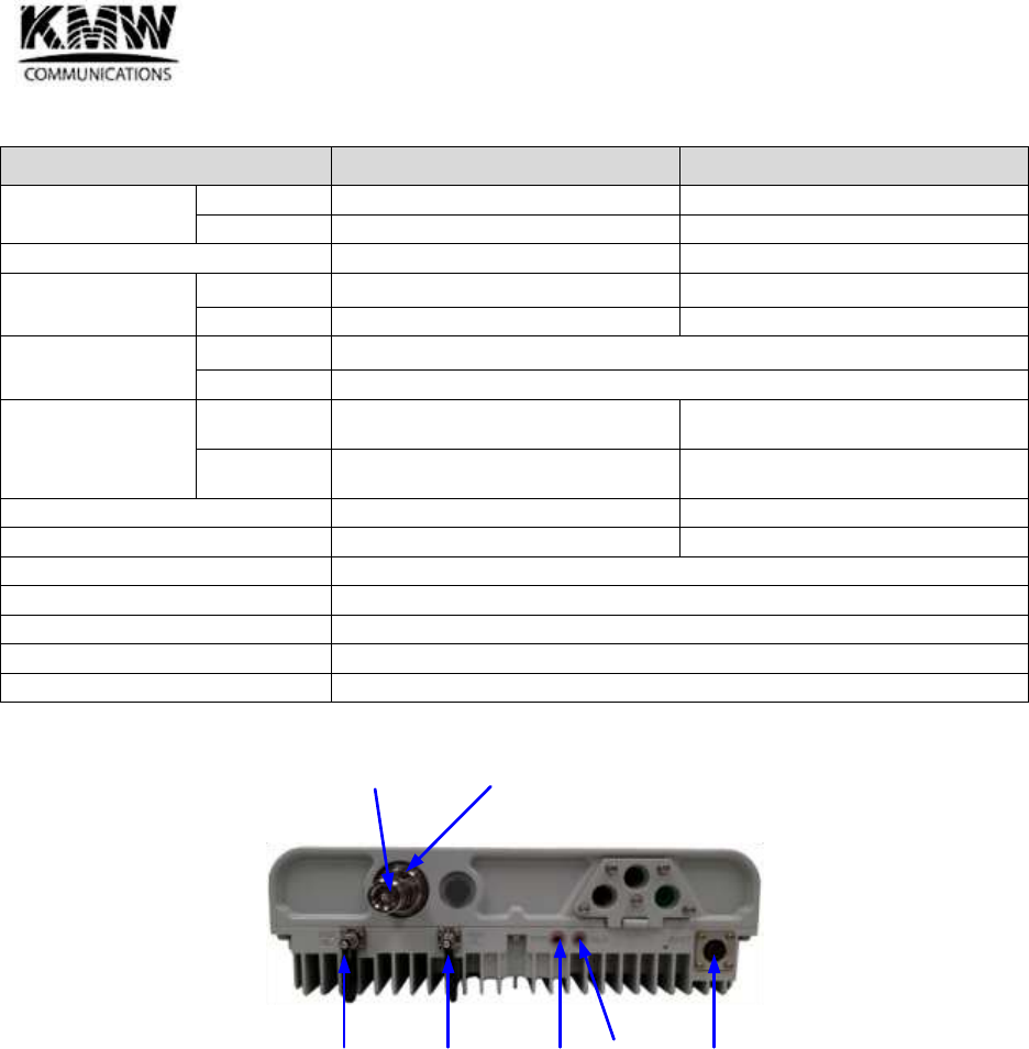
User Manual for POD Systems Revision: 0.7
© KMW USA Inc.
1818 E. Orangethrope Ave, Fullerton, CA 92831
Tel. +1 (714) 515-1100
www.kmwcomm.com
67
Table 2-36 PS700/800 RU - Specifications
PS700
PS800
Frequency Band
Downlink
758.0M - 775.0M
851M - 869M
Uplink
788.0M - 805.0M
806.0M - 824.0M
Bandwidth
17.0 MHz
18.0 MHz
Mean Gain
Downlink
36 ± 1.0 dB
36 ± 1.0 dB
Uplink
37 ± 1.0 dB
37 ± 1.0 dB
Maximum Gain
Downlink
67 dB
Uplink
37 dB
Ripple(p-p)
Downlink
3.5 dB @Full band
2.0 dB @759~774M
3.5 dB @Full band
2.0 dB @852~869M
Uplink
5.3 dB @Full band
2.0 dB @789~804M
5.3 dB @Full band
2.0 dB @807~824M
Maximum downlink output power
27 dBm
27 dBm
Uplink Noise Figure @center freq.
4.00 dB
4.00 dB
VSWR
< 1:1.7
Delay
< 5.00 us
EVM
< 5.0 % @E-TM 3.1
Operating band unwanted emissions
Meet FCC, LTE Repeater Spec.
Out of band emission
Meet FCC, LTE Repeater Spec.
2.2.2.3 RF ports and LED
Figure 2-59 Remote Unit - PS700/800 External Interfaces
RF port
- ANT port
Connected to Service antenna
Mini DIN, female type
- CPL port
Can be connected to spectrum analyzer to monitor downlink spectrum without interrupting wireless
service
SMA female type
- AUX UL & DL
Connected to expansion remote unit
QMA female type
AUX UL
Port
AUX DL
Port
ALM
LED
PWR
LED
BATT
Port
ANT Port CPL Port
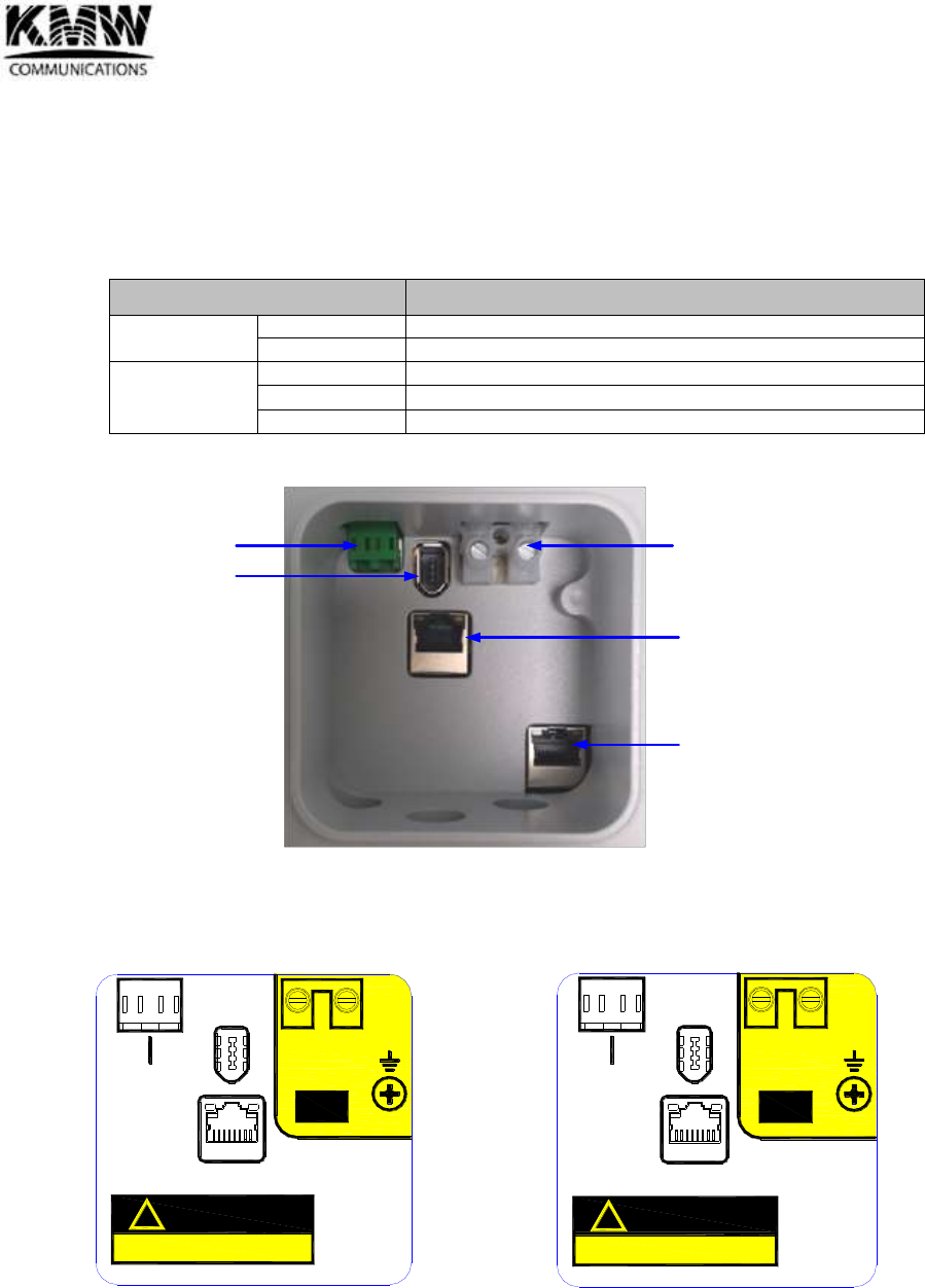
User Manual for POD Systems Revision: 0.7
© KMW USA Inc.
1818 E. Orangethrope Ave, Fullerton, CA 92831
Tel. +1 (714) 515-1100
www.kmwcomm.com
68
- TDD sync port
Provides TDD sync signal which can be used to synchronize with TDD signal measuring equipment such
as spectrum analyzer.
QMA female type
LED
Table 2-37 7/5/3 band RU LED Operation
Specifications
PWR
Solid Green
When power is on.
Off
When power is off.
ALM
Off
When PS700/800 band RU has no alarms.
Solid Yellow
When PS700/800 band RU has minor alarm.
Solid Red
When PS700/800 band RU has major alarm.
2.2.2.4 Debug Window
Figure 2-60 Debug Window
User can know the name for each port of RU by the sticker attached on the cover of debug window when user
opens debug window. User can verify whether RU is AC or DC type, and RU is main RU or expansion RU.
Main RU - AC type
Main RU - DC type
Optic Port AC or DC Power
input Port
Serial Port
Ethernet Port #1
Ethernet Port #2
GUI / EXT
DEBUG
UL DL
(OPTIC)
AC
(L) AC
(N)
AC
AC ONLY
CAUTION
!
DEBUG
GUI / EXT
UL DL
(OPTIC)
RTN
-48V
DC
DC ONLY
CAUTION
!
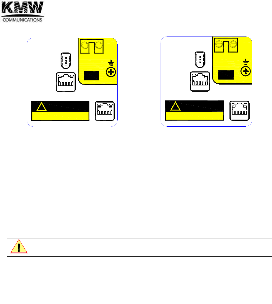
User Manual for POD Systems Revision: 0.7
© KMW USA Inc.
1818 E. Orangethrope Ave, Fullerton, CA 92831
Tel. +1 (714) 515-1100
www.kmwcomm.com
69
Expansion RU - AC type
Expansion RU - DC type
Figure 2-61 Port name for each RU type
Optic port
- Connected to Head-end
- Expansion RU doesn’t need optic port because it is connected to main RU through RF cable.
- LC/APC Female type
- Wavelength: 1310nm for downlink, 1550nm for uplink
Serial port (DEBUG): Used for internal debug
AC or DC power input port
- AC or DC power source is provided into Remote unit through this port.
110V AC, 50~60Hz or DC -48V
CAUTION
Must verify whether remote unit is AC or DC type before connecting input power to AC or DC input port
because AC and DC power input port has same form factor.
It might cause severe damage of remote unit when user connects AC input to DC power input port of DC
type RU or DC input to AC power input port of AC type RU in the wrong way.
User can verify easily whether remote unit is AC or DC type by checking the picture of sticker attached
to the debug window cover when you open it. (refer to Figure 2-61)
Ethernet Port
- Ethernet Port #1
Used as GUI Port to access web-based GUI when expansion RU is not connected
Used for connecting to expansion RU when expansion RU is connected to main RU.
Use GUI port in expansion RU to access web-based GUI when expansion RU is connected
- Ethernet Port #2
Used as GUI Port to access web-based GUI for only expansion RU
2.2.2.5 Battery Backup Port
GUI
AC
AC ONLY
CAUTION
!
AC
(L) AC
(N)
EXT
DEBUG
GUI
DC
DC ONLY
CAUTION
!
RTN
-48V
EXT
DEBUG
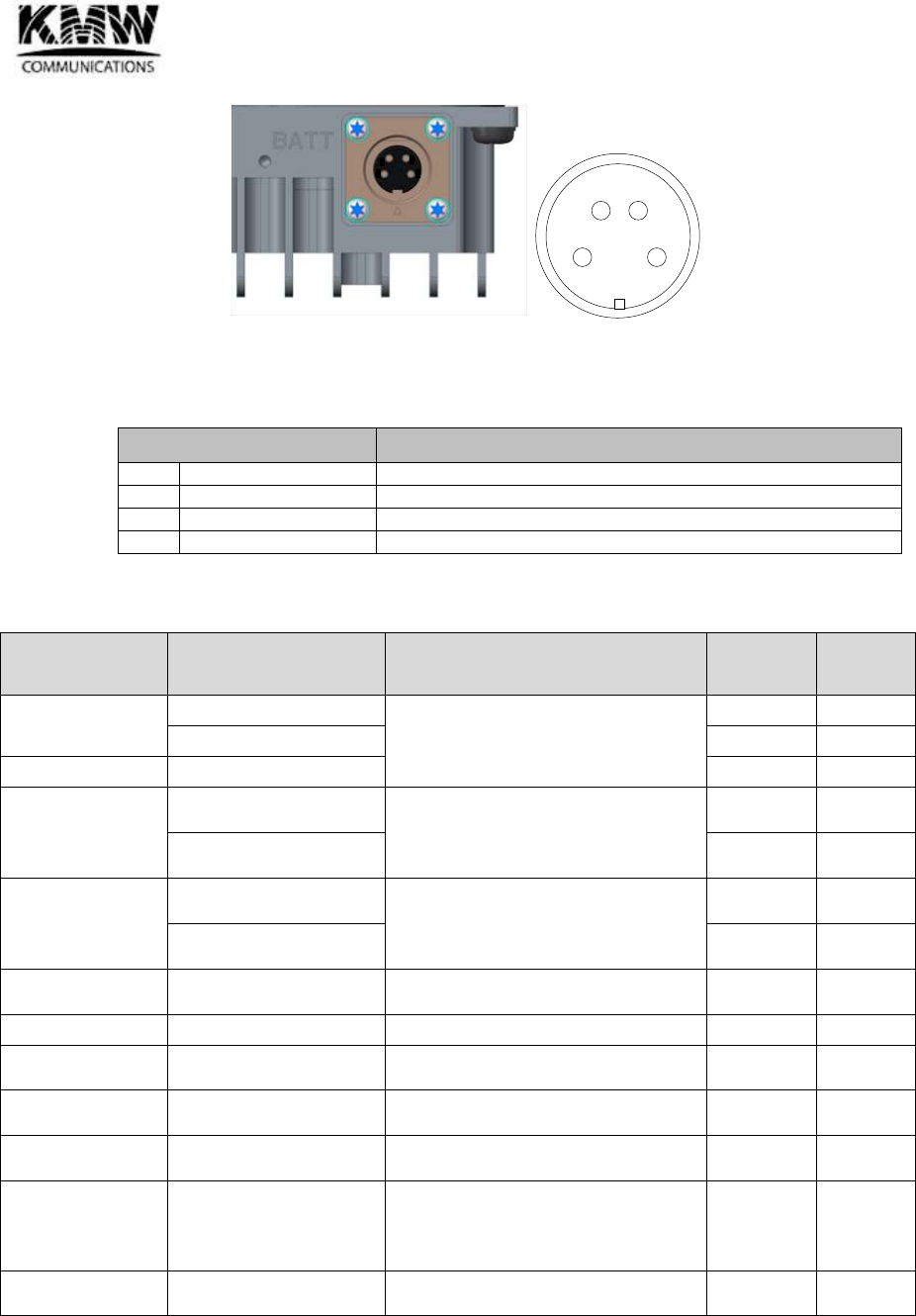
User Manual for POD Systems Revision: 0.7
© KMW USA Inc.
1818 E. Orangethrope Ave, Fullerton, CA 92831
Tel. +1 (714) 515-1100
www.kmwcomm.com
70
Figure 2-62 Battery backup port
- Connected to rechargeable battery
Table 2-38 Pin map - Battery Backup Port
Pin Assign
Specifications
1
DC
26V
2
DC
26V
3
GND
GND
4
GND
GND
2.2.2.6 Alarms
Table 2-39 PS700/800 band RU – Alarms
Alarm Name
Description
Remedy
Alarm
Severity
LED
color
High Temperature
Temperature too high
Check environment
Major
Red
Temperature high
Minor
Yellow
Low Temperature
Temperature too low
Minor
Yellow
Downlink High
Output Power
RF signal too high
Check Head-end downlink input level/
attenuator configuration/ ALC status
Major
Red
RF signal high
Major
Yellow
Uplink High Input
Power
RF signal too high
Check RU uplink input level/ attenuator
configuration/ ALC status
Major
Red
RF signal high
Major
Yellow
Downlink Low
Output Power
RF signal too low
Check Head-end downlink input level/
attenuator configuration/ RF cabling
Minor
Yellow
Link
Communication fail
Check cable connection
Major
Yellow
Freeze
The final stage of
Shutdown process
Check if shutdown process is going again
after reset
Major
Red
Downlink ALC
Activation
ALC activation
Check Head-end downlink input level/
attenuator configuration
Warning
Yellow
Uplink PLL Unlock
Uplink PLL unlock
Check if uplink PLL is still in unlocked
status after resetting PLL frequency
Minor
Yellow
VSWR
Bad RF cable/mismatched
service antenna
Check cable between RU and service
antenna, VSWR of service antenna
Major
Yellow
Optic LD Fail
Uplink LD fail
Check if optic LD fail alarm occurs again
after reset.
Major
Yellow
3 2
14

User Manual for POD Systems Revision: 0.7
© KMW USA Inc.
1818 E. Orangethrope Ave, Fullerton, CA 92831
Tel. +1 (714) 515-1100
www.kmwcomm.com
71
Optic PD Fail
Downlink PD fail
Check optic cable connection with H-
HOM
Major
Yellow
Optic Loss
Excess permitted optic loss
Check optic cable connection with H-
HOM / clean Optic connector and port
Minor
Yellow
High current
Power supply load too high
Check if current alarm occurs again after
reset.
Critical
Red
2.2.2.7 Grounding
- Refer to section 3.3.2

User Manual for POD Systems Revision: 0.7
© KMW USA Inc.
1818 E. Orangethrope Ave, Fullerton, CA 92831
Tel. +1 (714) 515-1100
www.kmwcomm.com
72
3. EQUIPMENT INSTALLATION
3.1 Inspection before equipment installation
Please follow these procedures before installing KMW POD equipments:
- Verify the number of packages received against the packing list.
- Check all packages for external damage; report any external damage to the shipping carrier.
- Open and check each package against the packing list. If any items are missing, contact KMW customer
service.
3.1.1 The Part list for each unit
3.1.1.1 Head-end Unit
3.1.1.1.1 POD-H-DMCU
Q’ty
Length
Comments
H-DMCU
1
H-CDU
1
Cable Duct Unit
Quick Installation Guide
1
Rack mount bracket
1
Power & signal cable between H-DMCU and H-PSU
1
30cm
Refer to section 4.1.1
Ethernet Cable for Web GUI or modem connection
1
2m
GND Cable
1
1m
3.1.1.1.2 POD-H-PSU
Q’ty
Length
Comments
H-PSU
1
Quick Installation Guide
1
Rack mount bracket
1
Power & signal cable between H-DMCU and H-PSU
1
2m
Refer to section 4.1.1
Ethernet Cable between H-DMCU and H-PSU
1
2m
GND Cable
1
1m
AC Cable (H-SPU-AC only)
1
2m
3.1.1.1.3 POD-H-SRU
Q’ty
Length
Comments
H-SRU
1
H-FAU
1
FAN Unit
Quick Installation Guide
1
Rack mount bracket
1
Power & signal cable between H-PSU and H-SRU
1
2m
Refer to section 4.1.1
Power & signal cable between H-SRU and H-FAU
1
2m
GND Cable
1
1m
3.1.1.1.4 POD-H-SCM
Q’ty
Length
Comments
H-SCM
1
Ethernet Cable between H-DMCU and H-SCM, or
between H-MCM and H-SCM
1
2m
Refer to section 4.1.1
3.1.1.1.5 POD-H-MCM
Q’ty
Length
Comments
H-MCM
1
Ethernet Cable between H-DMCU and H-MCM
1
2m
Refer to section 4.1.1

User Manual for POD Systems Revision: 0.7
© KMW USA Inc.
1818 E. Orangethrope Ave, Fullerton, CA 92831
Tel. +1 (714) 515-1100
www.kmwcomm.com
73
3.1.1.2 Remote Unit
3.1.1.2.1 7/5/3 band RU, PS700/800 RU
Q’ty
Length
Comments
7/5/3 band RU or PS700/800 RU
1
Quick Installation Guide
1
wall mount bracket
1
AC or DC input power cable
1
2m
Refer to section 4.2.1.1
Ethernet Cable for Web GUI or modem connection
1
2m
GND Cable
1
2m
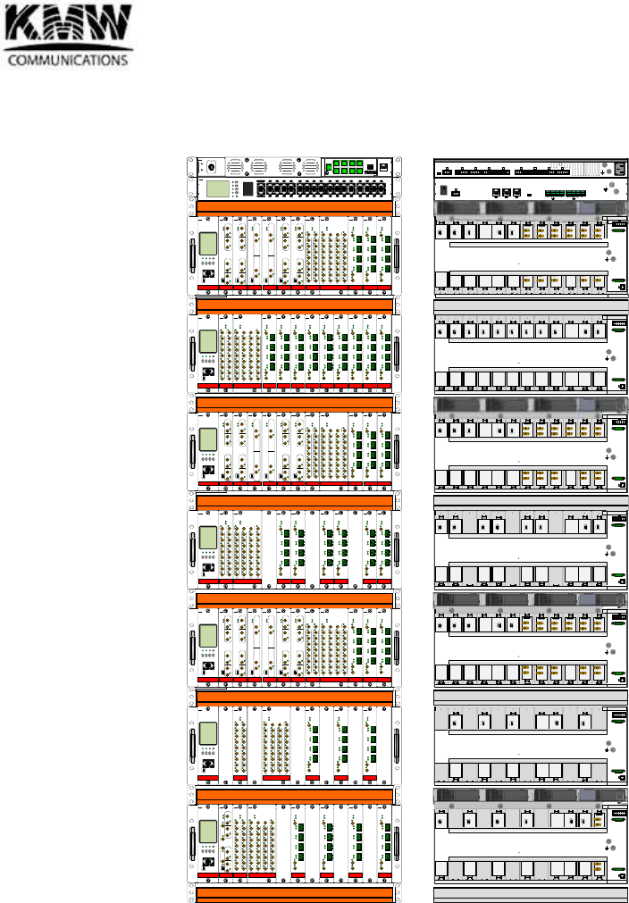
User Manual for POD Systems Revision: 0.7
© KMW USA Inc.
1818 E. Orangethrope Ave, Fullerton, CA 92831
Tel. +1 (714) 515-1100
www.kmwcomm.com
74
3.2 Head-end Unit Equipment Installation
3.2.1 Installation Head-end Unit in a 19” rack
Figure 3-1 Head-end Unit Rack Mount (Front & Rear view)
1 2 3 4 5 6 7 8 9 10 11 12
ENT
Up
Down
ESC
Reset
Run
DMCU
Alarm
Link
HE
Alarm
RU
Alarm
1
2
3
4
5 7
6 8
9 11 13 15
10 12 14 16
17 19 21 23
18 20 22 24
25 27 29 31
26 28 30 32
Modem
Web GUI
KMW
DMCU
HPSU
Power
Alarm
#1 #2 #3 #4
#5 #6 #7 #8
DMCU
#1 #2 #3 #4
1 2 1 2
Group Rack
KMW
HFM-L-W
UL MON
DL MON
DL Out
UL In
UL MON
DL MON
DL Out
UL In
PWR
ALM
Path A
Path B
KMW
HFM-L-A
UL MON
DL MON
DL Out
UL In
UL MON
DL MON
DL Out
UL In
PWR
ALM
Path A
Path B
KMW
HFM-L-7
UL MON
DL MON
DL Out
UL In
UL Mon
DL MON
DL Out
UL In
PWR
ALM
Path A
Path B
KMW
HFM-L-C
UL MON
DL MON
DL Out
UL In
UL MON
DL MON
DL Out
UL In
PWR
ALM
Path A
Path B
KMW
HFM-L-P
DL Out
UL MON
UL In
DL MON
PWR
ALM
PCS
KMW
Run Link ALM Reset
ENT Up Down ESC
DMCU Web GUI
SCM
KMW
HCM-8
PWR
ALM
DL
COM
#1
#2
#3
#4
#5
#6
#7
#8
#1
#2
#3
#4
#5
#6
#7
#8
UL
COM
DL UL
KMW
HOM-L
PWR
ALM
UL Out
DL In
T_Sync
DL
UL
DL
UL
DL
UL
DL
UL
KMW
# 1
# 2
# 3
# 4
1 2 3 4 5 6 7 8 9 10 11 12
HOM-L
PWR
ALM
UL Out
DL In
T_Sync
DL
UL
DL
UL
DL
UL
DL
UL
KMW
# 1
# 2
# 3
# 4
HOM-L
PWR
ALM
UL Out
DL In
T_Sync
DL
UL
DL
UL
DL
UL
DL
UL
KMW
# 1
# 2
# 3
# 4
DTM-8X8
PWR
ALM
KMW
VHF
UHF
#1
#2
#3
#4
#5
#6
#7
#8
#1
#2
#3
#4
#5
#6
#7
#8
DL MON
DL UL
UL MON
#1
#2
#3
#4
#5
#6
#7
#8
#1
#2
#3
#4
#5
#6
#7
#8
VHF
UHF
IN OUT IN OUT
HFM-L-P
DL Out
UL MON
UL In
DL MON
PWR
ALM
PCS
KMW
1 2 3 4 5 6 7 8 9 10 11 12
HCM-8
PWR
ALM
DL
COM
#1
#2
#3
#4
#5
#6
#7
#8
#1
#2
#3
#4
#5
#6
#7
#8
UL
COM
DL UL
KMW
DTM-8X8
PWR
ALM
KMW
VHF
UHF
#1
#2
#3
#4
#5
#6
#7
#8
#1
#2
#3
#4
#5
#6
#7
#8
DL MON
DL UL
UL MON
#1
#2
#3
#4
#5
#6
#7
#8
#1
#2
#3
#4
#5
#6
#7
#8
VHF
UHF
IN OUT IN OUT
Run Link ALM Reset
ENT Up Down ESC
DMCU Web GUI
SCM
KMW
HOM-L
PWR
ALM
UL Out
DL In
T_Sync
DL
UL
DL
UL
DL
UL
DL
UL
KMW
# 1
# 2
# 3
# 4
HOM-L
PWR
ALM
UL Out
DL In
T_Sync
DL
UL
DL
UL
DL
UL
DL
UL
KMW
# 1
# 2
# 3
# 4
HOM-L
PWR
ALM
UL Out
DL In
T_Sync
DL
UL
DL
UL
DL
UL
DL
UL
KMW
# 1
# 2
# 3
# 4
Run Link ALM Reset
ENT Up Down ESC
DMCU Web GUI
SCM
KMW
HCM-8
PWR
ALM
DL
COM
#1
#2
#3
#4
#5
#6
#7
#8
#1
#2
#3
#4
#5
#6
#7
#8
UL
COM
DL UL
KMW
HOM-L
PWR
ALM
UL Out
DL In
T_Sync
DL
UL
DL
UL
DL
UL
DL
UL
KMW
# 1
# 2
# 3
# 4
1 2 3 4 5 6 7 8 9 10 11 12
HOM-L
PWR
ALM
UL Out
DL In
T_Sync
DL
UL
DL
UL
DL
UL
DL
UL
KMW
# 1
# 2
# 3
# 4
HOM-L
PWR
ALM
UL Out
DL In
T_Sync
DL
UL
DL
UL
DL
UL
DL
UL
KMW
# 1
# 2
# 3
# 4
HOM-L
PWR
ALM
UL Out
DL In
T_Sync
DL
UL
DL
UL
DL
UL
DL
UL
KMW
# 1
# 2
# 3
# 4
DTM-8X8
PWR
ALM
KMW
VHF
UHF
#1
#2
#3
#4
#5
#6
#7
#8
#1
#2
#3
#4
#5
#6
#7
#8
DL MON
DL UL
UL MON
#1
#2
#3
#4
#5
#6
#7
#8
#1
#2
#3
#4
#5
#6
#7
#8
VHF
UHF
IN OUT IN OUT
HFM-L-B
UL MON
DL MON
DLOut
UL In
UL MON
DL MON
DL Out
UL In
PWR
ALM
Path A
Path B
#1
#2
#3
#4
T-Sync
KMW
HOM-L
PWR
ALM
UL Out
DL In
T_Sync
DL
UL
DL
UL
DL
UL
DL
UL
KMW
# 1
# 2
# 3
# 4
HOM-L
PWR
ALM
UL Out
DL In
T_Sync
DL
UL
DL
UL
DL
UL
DL
UL
KMW
# 1
# 2
# 3
# 4
HOM-L
PWR
ALM
UL Out
DL In
T_Sync
DL
UL
DL
UL
DL
UL
DL
UL
KMW
# 1
# 2
# 3
# 4
HOM-L
PWR
ALM
UL Out
DL In
T_Sync
DL
UL
DL
UL
DL
UL
DL
UL
KMW
# 1
# 2
# 3
# 4
HOM-L
PWR
ALM
UL Out
DL In
T_Sync
DL
UL
DL
UL
DL
UL
DL
UL
KMW
# 1
# 2
# 3
# 4
HOM-L
PWR
ALM
UL Out
DL In
T_Sync
DL
UL
DL
UL
DL
UL
DL
UL
KMW
# 1
# 2
# 3
# 4
HOM-L
PWR
ALM
UL Out
DL In
T_Sync
DL
UL
DL
UL
DL
UL
DL
UL
KMW
# 1
# 2
# 3
# 4
HOM-L
PWR
ALM
UL Out
DL In
T_Sync
DL
UL
DL
UL
DL
UL
DL
UL
KMW
# 1
# 2
# 3
# 4
HOM-L
PWR
ALM
UL Out
DL In
T_Sync
DL
UL
DL
UL
DL
UL
DL
UL
KMW
# 1
# 2
# 3
# 4
HPSU
Power SW
DMCU
1 2 3
External Alarm
Input Output
1 2 3 4 5 6 7 8
#1 #2 #3 #4 #5 #6 #7 #8
DMCU HSRU
1 2 3 4 5 6 7 8 9 10 11 12
DL / UL (A)
UL Div (A)
DL / UL (B)
UL Div (B)
700M
┌
┌
└
└
DL / UL (A)
UL Div (A)
DL / UL (B)
UL Div (B)
850M
┌
┌
└
└
DL / UL (A)
UL Div (A)
DL / UL (B)
UL Div (B)
AWS
┌
┌
└
└
DL / UL (A)
UL Div (A)
PCS
┌
┌
DL / UL (A)
UL Div (A)
DL / UL (B)
UL Div (B)
WCS
┌
┌
└
└
DL / UL (A)
UL Div (A)
DL / UL (B)
UL Div (B)
WCS
┌
┌
└
└
- 30 -
- 30 -
#12 #11 #10 #9 #8 #7 #6 #5 #4 #3 #2 #1
HPSU
FUSE
Spare Fuse
FAN
- 30 -
- 30 -
#12 #11 #10 #9 #8 #7 #6 #5 #4 #3 #2 #1
HPSU
FUSE
Spare Fuse
FAN
DL / UL (A)
UL Div (A)
DL / UL (B)
UL Div (B)
WCS
┌
┌
└
└
1 2 3 4 5 6 7 8 9 10 11 12
DL / UL (A)
UL Div (A)
DL / UL (B)
UL Div (B)
700M
┌
┌
└
└
DL / UL (A)
UL Div (A)
DL / UL (B)
UL Div (B)
850M
┌
┌
└
└
DL / UL (A)
UL Div (A)
DL / UL (B)
UL Div (B)
AWS
┌
┌
└
└
DL / UL (A)
UL Div (A)
PCS
┌
┌
DL / UL (A)
UL Div (A)
DL / UL (B)
UL Div (B)
WCS
┌
┌
└
└
- 30 -
- 30 -
#12 #11 #10 #9 #8 #7 #6 #5 #4 #3 #2 #1
HPSU
FUSE
Spare Fuse
FAN
DL / UL (A)
UL Div (A)
DL / UL (B)
UL Div (B)
700M
┌
┌
└
└
- 30 -
- 30 -
#12 #11 #10 #9 #8 #7 #6 #5 #4 #3 #2 #1
HPSU
FUSE
Spare Fuse
FAN
1 2 3 4 5 6 7 8 9 10 11 12
DL / UL (A)
UL Div (A)
DL / UL (B)
UL Div (B)
WCS
┌
┌
└
└
- 30 -
- 30 -
#12 #11 #10 #9 #8 #7 #6 #5 #4 #3 #2 #1
HPSU
FUSE
Spare Fuse
FAN
1 2 3 4 5 6 7 8 9 10 11 12
DL / UL (A)
UL Div (A)
DL / UL (B)
UL Div (B)
700M
┌
┌
└
└
DL / UL (A)
UL Div (A)
DL / UL (B)
UL Div (B)
850M
┌
┌
└
└
DL / UL (A)
UL Div (A)
DL / UL (B)
UL Div (B)
AWS
┌
┌
└
└
DL / UL (A)
UL Div (A)
PCS
┌
┌
DL / UL (A)
UL Div (A)
DL / UL (B)
UL Div (B)
WCS
┌
┌
└
└
- 30 -
- 30 -
#12 #11 #10 #9 #8 #7 #6 #5 #4 #3 #2 #1
HPSU
FUSE
Spare Fuse
FAN
- 30 -
- 30 -
#12 #11 #10 #9 #8 #7 #6 #5 #4 #3 #2 #1
HPSU
FUSE
Spare Fuse
FAN
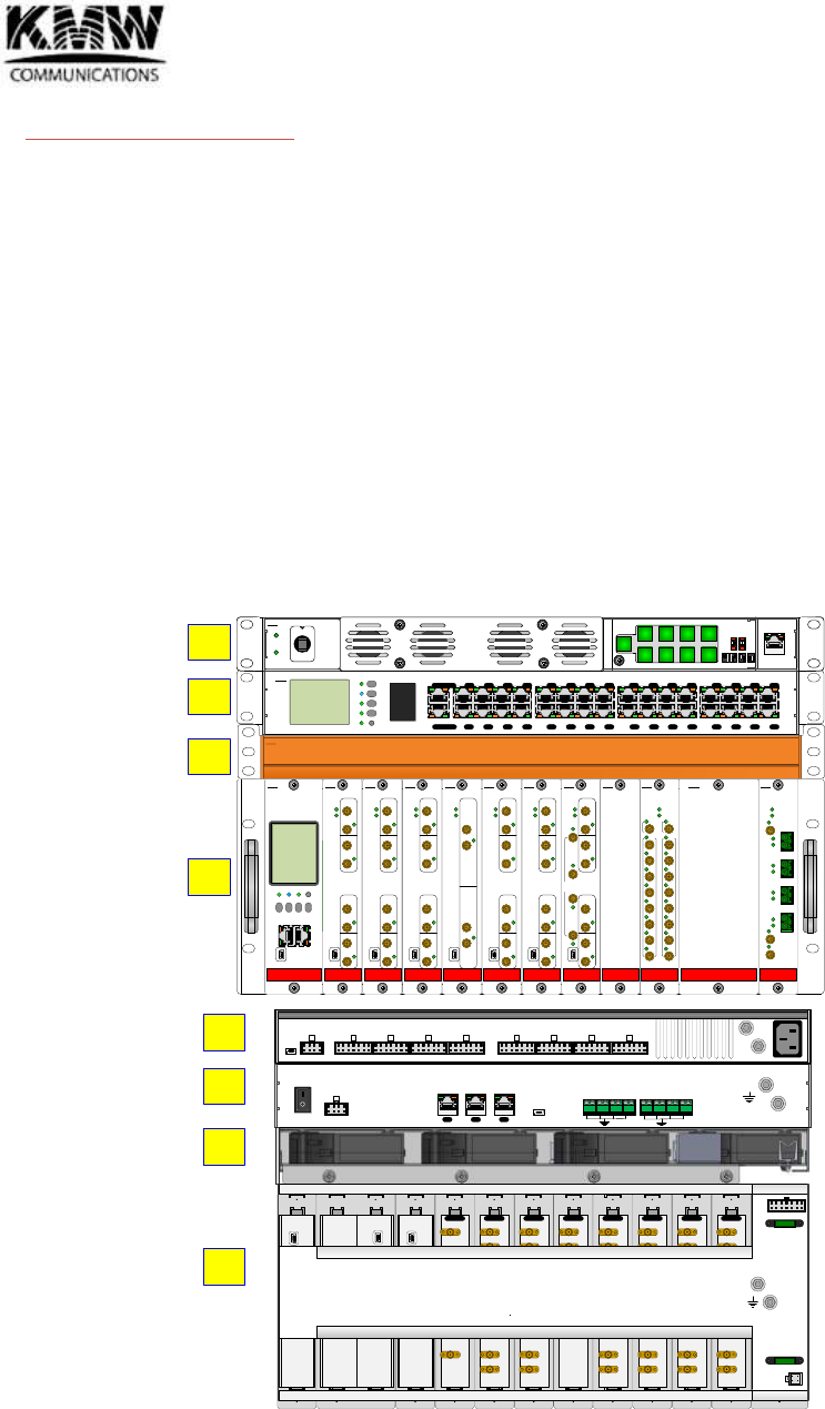
User Manual for POD Systems Revision: 0.7
© KMW USA Inc.
1818 E. Orangethrope Ave, Fullerton, CA 92831
Tel. +1 (714) 515-1100
www.kmwcomm.com
75
CAUTIONS AND CONSIDERATIONS
- POD Head-end system should be installed inside building only and mounts in a standard 19” rack.
- The rule for installing FAN unit: refer to section -
- Allowed minimum clearance
Front and Rear: 10” (254mm)
Both sides:2” (51mm)
Top and bottom: No clearance is required.
3.2.1.1 The sequence for mounting head-end unit
The sequence for mounting each head-end unit is as below.
- (1)H-PSU → (2)H-DMCU →(3-1)H-CDU #1 →(4-1)H-SRU #1 … (3-7)H-CDU #7 →(4-7)H-SRU #7 →(5)H-FAU
H-PSU must be installed at the top of the rack.
H-DMCU must be installed right below H-PSU on the rack.
H-SRU must be installed below H-DMCU with skip 1U gap
H-CDU must be installed between H-DMCU and H-SRU.
H-FAU (FAN Unit) will be installed in the empty space from rear side of H-CDU (Cable duck Unit).
- Regarding FAN installation, refer to section -.
Figure 3-2 Head-end Unit - Rack Mount Sequence
FEM-L-W
UL MON
DL MON
DL Out
UL In
UL MON
DL MON
DL Out
UL In
PWR
ALM
Path A
Path B
KMW
FEM-L-A
UL MON
DL MON
DL Out
UL In
UL MON
DL MON
DL Out
UL In
PWR
ALM
Path A
Path B
KMW
FEM-L-7
UL MON
DL MON
DL Out
UL In
UL Mon
DL MON
DL Out
UL In
PWR
ALM
Path A
Path B
KMW
FEM-L-S8
UL MON
DL MON
DL Out
UL In
UL MON
DL MON
DL Out
UL In
PWR
ALM
Path A
Path B
KMW
FEM-L-C
UL MON
DL MON
DL Out
UL In
UL MON
DL MON
DL Out
UL In
PWR
ALM
Path A
Path B
KMW
FEM-L-B
UL MON
DL MON
DLOut
UL In
UL MON
DL MON
DL Out
UL In
PWR
ALM
Path A
Path B
#1
#2
#3
#4
T-Sync
KMW
FEM-L-P
DL Out
UL MON
UL In
DL MON
PWR
ALM
PCS
KMW
Run Link ALM Reset
ENT Up Down ESC
DMCU Web GUI
SCM
KMW
COM-8
PWR
ALM
DL
COM
#1
#2
#3
#4
#5
#6
#7
#8
#1
#2
#3
#4
#5
#6
#7
#8
UL
COM
DL UL
KMW
HOM-L
PWR
ALM
UL Out
DL In
T_Sync
DL
UL
DL
UL
DL
UL
DL
UL
KMW
# 1
# 2
# 3
# 4
BLANK
KMW
BLANK
KMW
1 2 3 4 5 6 7 8 9 10 11 12
KMW
ENT
Up
Down
ESC
Reset
Run
DMCU
Alarm
Link
HE
Alarm
RU
Alarm
1
2
3
4
5 7
6 8
9 11 13 15
10 12 14 16
17 19 21 23
18 20 22 24
25 27 29 31
26 28 30 32
Modem
Web GUI
KMW
DMCU
HPSU
Power
Alarm
#1 #2 #3 #4
#5 #6 #7 #8
DMCU
#1 #2 #3 #4
1 2 1 2
Group Rack
KMW
1
2
3-1
4-1
DL / UL (A)
UL Div (A)
DL / UL (B)
UL Div (B)
700M
┌
┌
└
└
DL / UL (A)
UL Div (A)
DL / UL (B)
UL Div (B)
P7/P8
┌
┌
└
└
DL / UL (A)
UL Div (A)
DL / UL (B)
UL Div (B)
S8
┌
┌
└
└
DL / UL (A)
UL Div (A)
DL / UL (B)
UL Div (B)
850M
┌
┌
└
└
DL / UL (A)
UL Div (A)
PCS
┌
┌
DL / UL (A)
UL Div (A)
DL / UL (B)
UL Div (B)
AWS
┌
┌
└
└
DL / UL (A)
UL Div (A)
DL / UL (B)
UL Div (B)
WCS
┌
┌
└
└
DL / UL (A)
DL / UL (B)
BRS
┌
└
- 30 -
- 30 -
#12 #11 #10 #9 #8 #7 #6 #5 #4 #3 #2 #1
HPSU
FUSE
Spare Fuse
FAN
HPSU
Power SW
DMCU
1 2 3
External Alarm
Input Output
1 2 3 4 5 6 7 8
#1 #2 #3 #4 #5 #6 #7 #8
DMCU HSRU
1
2
5
4-1
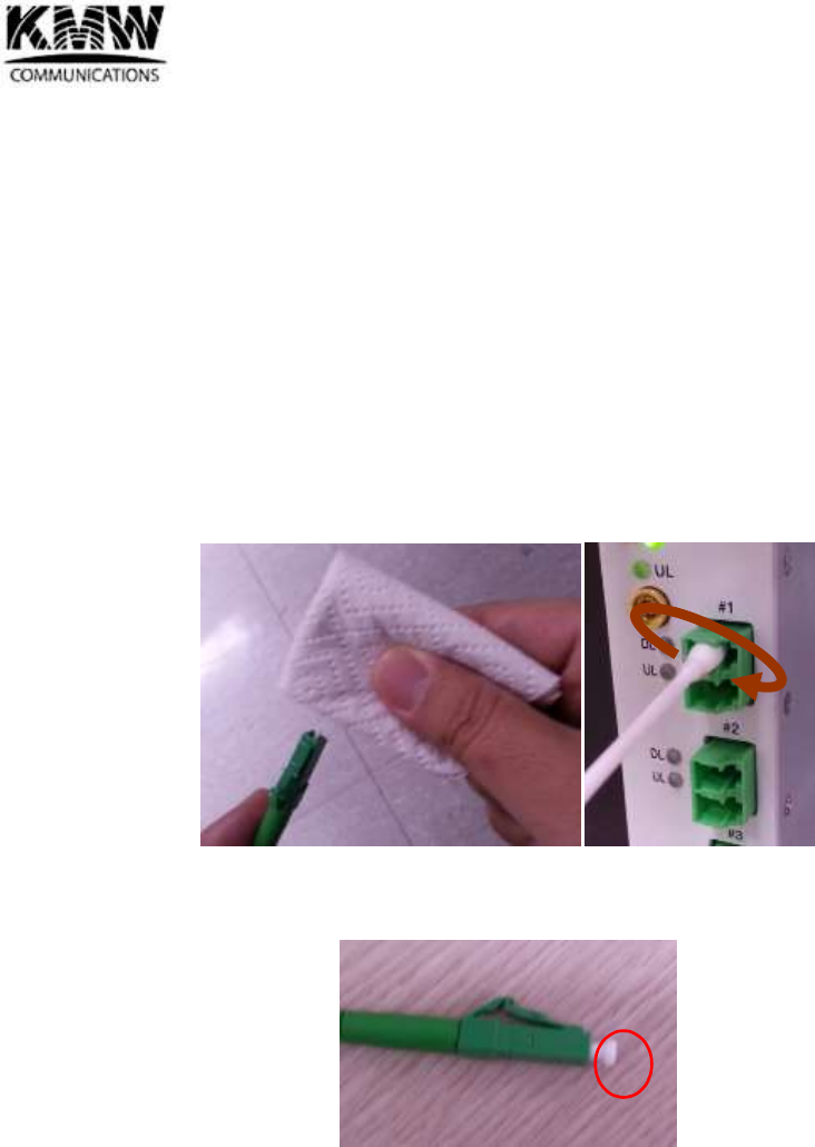
User Manual for POD Systems Revision: 0.7
© KMW USA Inc.
1818 E. Orangethrope Ave, Fullerton, CA 92831
Tel. +1 (714) 515-1100
www.kmwcomm.com
76
3.2.2 Grounding
The grounding terminals are located at the rear of H-PSU, H-DMCU, and H-SRU. They must be grounded properly
before powering on the equipment.
Figure 3-10 Head-end units Grounding
3.2.3 Optic port Cleaning
We recommend that optic connector should be cleaned using a dry optical cleaning swab or tissue in a dry
environment before connecting optic cable. Also, if the expected optic loss is 1.5dB higher than the loss
reported in the Web-GUI, the optic loss should be minimized through cleaning optic connectors.(Figure 3-3)
The unused optic ports are should be covered with a protective dust cap. (Figure 3-4)
Figure 3-3 Optic Connector Cleaning (left) and Optic Port Cleaning (right)
Figure 3-4 LC/APC Optic Connector Dust Cap
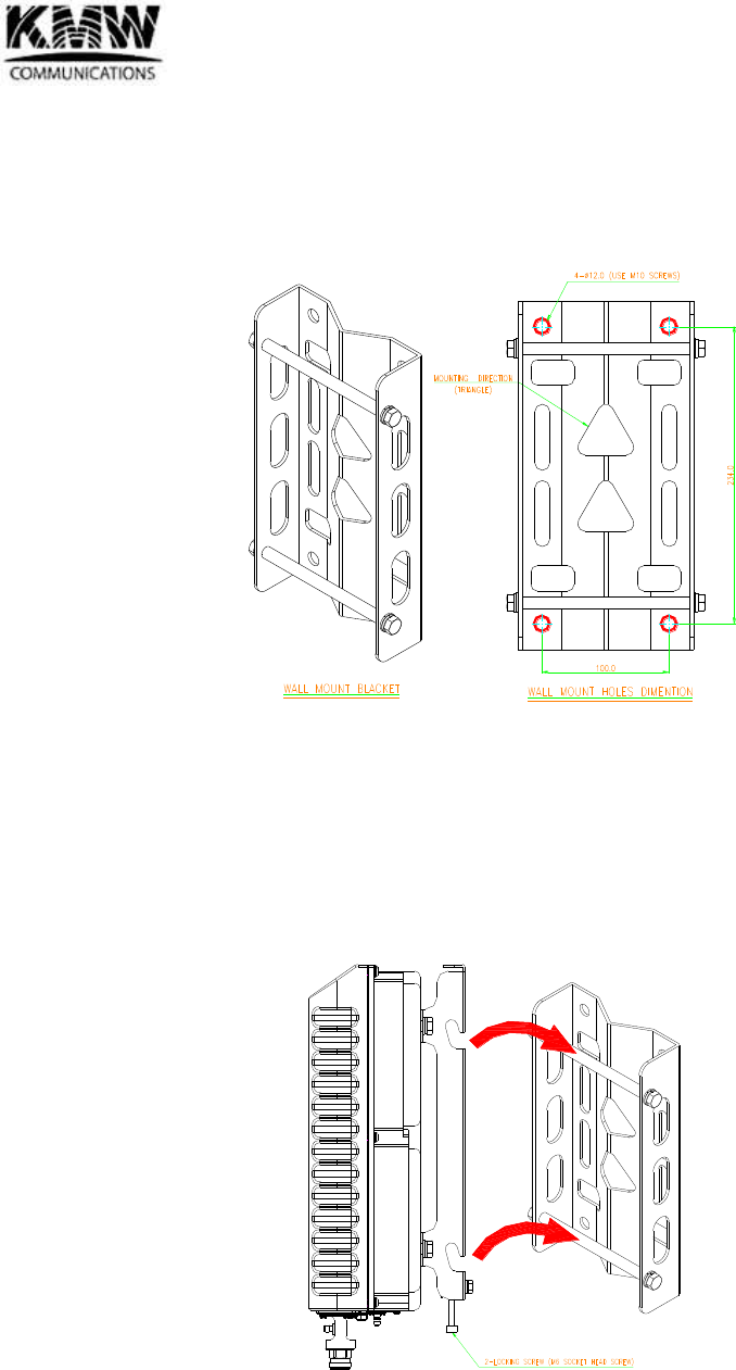
User Manual for POD Systems Revision: 0.7
© KMW USA Inc.
1818 E. Orangethrope Ave, Fullerton, CA 92831
Tel. +1 (714) 515-1100
www.kmwcomm.com
77
3.3 Remote Unit
3.3.1 Wall Mount for 3/5/7 band RU and PS700/800 RU
Wall mounting procedure
- Check the suitability of the wall-mounting kit and the wall based on Figure 3-5
Figure 3-5 3/5/7 band RU, PS700/800 RU – wall mount bracket
- Install the wall-mounting bracket using 4 x M10 screw anchors (not included**) according to the drilling
layout. Confirm that the bracket is securely fastened to the wall.
** The M10 screw anchors are not included as part of the RU delivery because the suitable type
depends on the on-site conditions such as wall structure and materials. Therefore, use screw anchors
that are appropriate for the mounting surface.
- Install the Remote Unit on the wall-mounting bracket by lifting the RU into place and lowering it down onto
the bracket. The M6 pins must align with the slots in the bracket to support the RU.
Figure 3-6 3/5/7 band RU, PS700/800 RU – Install RU into wall mount bracket
- Fasten the lower section of the Remote Unit to the bracket using a washer and 2 x M6 screws (on both
sides). Slide a washer over each screw and then insert the screw and tighten it securely.
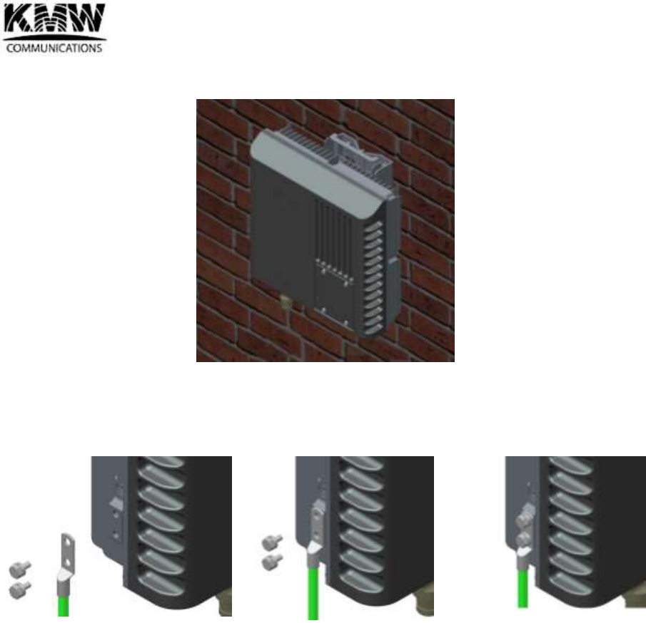
User Manual for POD Systems Revision: 0.7
© KMW USA Inc.
1818 E. Orangethrope Ave, Fullerton, CA 92831
Tel. +1 (714) 515-1100
www.kmwcomm.com
78
- Confirm that all screws have been fastened and the unit is securely mounted to the wall.
Figure 3-7 3/5/7 band RU, PS700/800 RU – RU installed on the wall
3.3.2 Grounding
3.3.2.1 3/5/7 band RU, PS700/800 RU
Step A
Step B
Step C
Figure 3-8 3/5/7 band RU grounding
- Connect an earth-bonding cable to the grounding bolt connection provided on the outside of the remote
unit (Left-side) as shown in Figure 3-8. Do not use earth-bonding cable to connect other external devices.
loosen the two hex bolts attached to remote unit as illustrated in Figure 3-8, Step A
Connect the earth-bonding cable to remote unit as illustrated in Figure 3-8, Step B
Then, fasten all parts again by tightening the hex bolts as illustrated in Figure 3-8, Step C
- Connect the other end of the ground wire to a suitable permanent ground following local electrical code
practices.
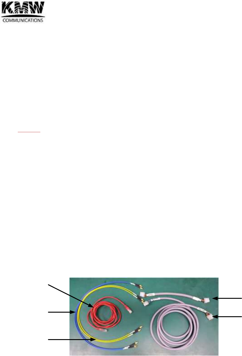
User Manual for POD Systems Revision: 0.7
© KMW USA Inc.
1818 E. Orangethrope Ave, Fullerton, CA 92831
Tel. +1 (714) 515-1100
www.kmwcomm.com
79
4. CABLE CONNECTION
4.1 Head-end Unit Cable Connection
4.1.1 Cable
RF Cable
- Between modules in H-SRU or between H-SRUs
Downlink
Connector: SMB-L, female
Cable Color: Blue Jacket
Uplink
Connector: SMB-L, female
Cable Color: Yellow Jacket
- CAUTION) RF cable with 35” length will be provided normally. 60” and 90” RF cable can be provided by user’s
special order.
Ethernet cable
- Between H-DMCU and H-SCM or H-PSU
Connector: RJ45, female
Length: 2m
Power & Signal cable
- Between H-DMCU and H-PSU
Length: 30cm
- Between H-SRU and H-PSU
Length: 2m
- Between H-SRU and H-FAU
Length: 40cm
- AC Power Cable
Length: 2m
GND Cable
- H-DMCU, H-PSU, H-SRU
Length: 1m
Figure 4-1 Head-end - cables
Downlink
RF cable
Uplink
RF cable
Ethernet
Cable H-DMCU~
H-PSU
H-SRU~
H-PSU
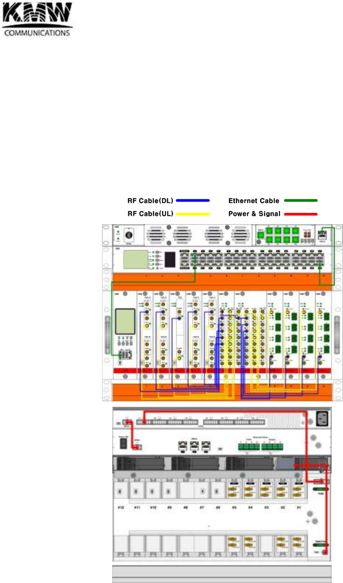
User Manual for POD Systems Revision: 0.7
© KMW USA Inc.
1818 E. Orangethrope Ave, Fullerton, CA 92831
Tel. +1 (714) 515-1100
www.kmwcomm.com
80
4.1.2 Cable Connection Example for frequency bands with FDD type
POD DAS System configuration
- H-DMCU : 1ea
- H-PSU: 1ea
- H-SRU: 1ea (H-SCM, H-FAU, H-CDU)
- H-FEM: 5ea (FEM-L-7, FEM-L-C, FEM-L-P, FEM-L-A, FEM-L-W)
- H-COM: 1ea
- H-DTM: 1ea
- H-HOM-L: 4ea
Figure 4-2 shows cable connection example for frequency bands with FDD type.
Figure 4-2 Cable Connection Example for frequency bands with FDD type

User Manual for POD Systems Revision: 0.7
© KMW USA Inc.
1818 E. Orangethrope Ave, Fullerton, CA 92831
Tel. +1 (714) 515-1100
www.kmwcomm.com
81
RF cable connection
- The RF ports for BTS connection are located in the back of H-SRU.
- All RF ports for the connection between modules installed in H-SRU are located in the front of H-SRU.
Optic cable connection
- The optic ports for the connection with Remote units are located in the front panel of H-HOM-L.
Ethernet cable connection
From
To
Comments
Ethernet cable
H-DMCU
H-SCM
H-DMCU
H-PSU
Power & signal cable connection
From
To
Comments
Power & Signal cable
H-PSU
H-DMCU
H-PSU
H-SRU
H-SRU
H-FAU
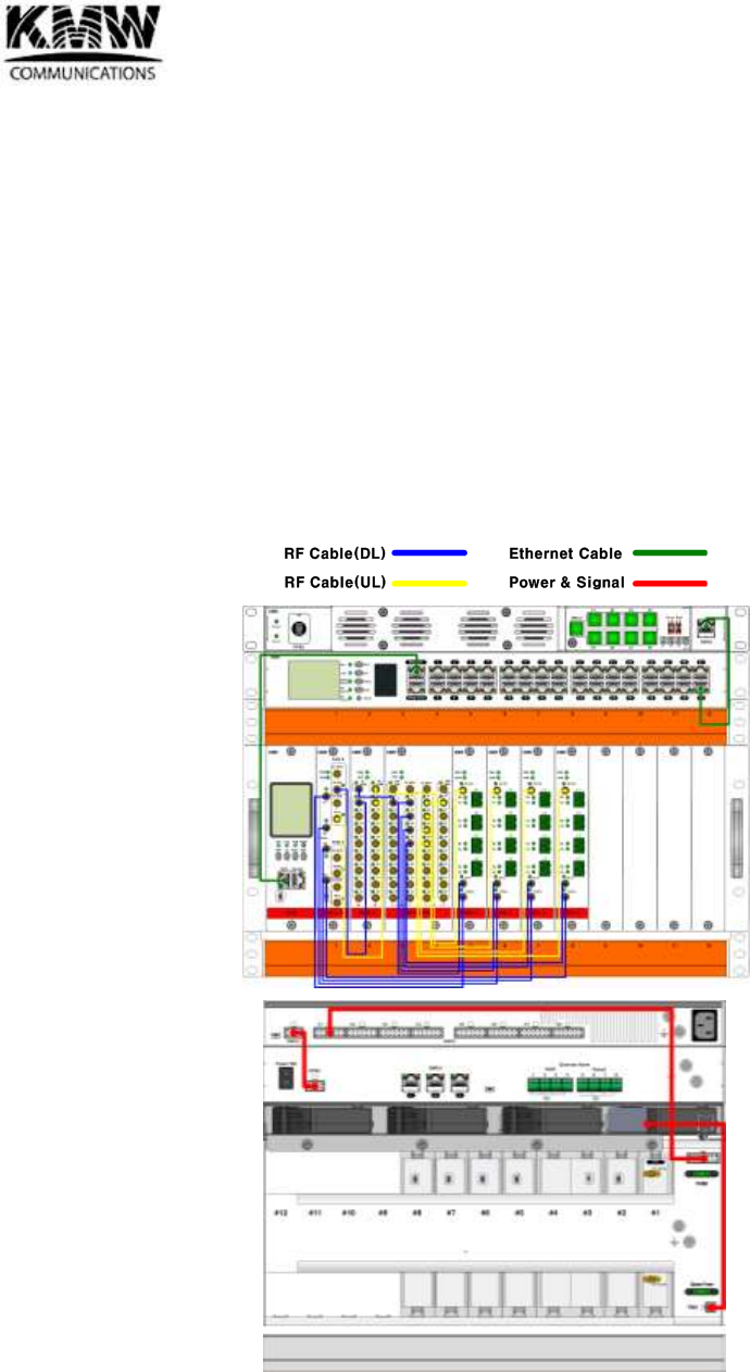
User Manual for POD Systems Revision: 0.7
© KMW USA Inc.
1818 E. Orangethrope Ave, Fullerton, CA 92831
Tel. +1 (714) 515-1100
www.kmwcomm.com
82
4.1.3 Cable Connection for TDD 2.6G frequency band
POD DAS System configuration
- H-DMCU : 1ea
- H-PSU: 1ea
- H-SRU: 1ea (H-SCM, H-FAU, H-CDU)
- H-FEM: 1ea (FEM-L-B)
- H-COM: 1ea
- H-DTM: 1ea
- H-HOM-L: 4ea
Figure 4-3 shows cable connection example for TDD 2.6G frequency band.
In case of 2.6G supporting TDD system, TDD sync signal generated from H-FEM-L-B should be transferred to RU
to synchronize TDD timing in overall POD DAS system. H-FEM-L-B has 4 TDD sync output port and each TDD sync
port is connected to TS sync port of H-HOM-L to transfer TDD signal over optic cable.
Figure 4-3 Cable Connection Example #1 for TDD 2.6G frequency band

User Manual for POD Systems Revision: 0.7
© KMW USA Inc.
1818 E. Orangethrope Ave, Fullerton, CA 92831
Tel. +1 (714) 515-1100
www.kmwcomm.com
83
RF cable connection
- The RF ports for BTS connection are located in the back of H-SRU.
- All RF ports for the connection between modules installed in H-SRU are located in the front of H-SRU.
RF cable connection for TDD sync signal transfer
From
To
Module
port
Module
port
RF cable
H-FEM-L(H)-B
T-Sync #1~#4
H-HOM
T_Sync
Optic cable connection
- The optic ports for the connection with Remote units are located in the front panel of H-HOM-L.
Ethernet cable connection
From
To
Comments
Ethernet cable
H-DMCU
H-SCM
H-DMCU
H-PSU
Power & signal cable connection
From
To
Comments
Power & Signal cable
H-PSU
H-DMCU
H-PSU
H-SRU
H-SRU
H-FAU
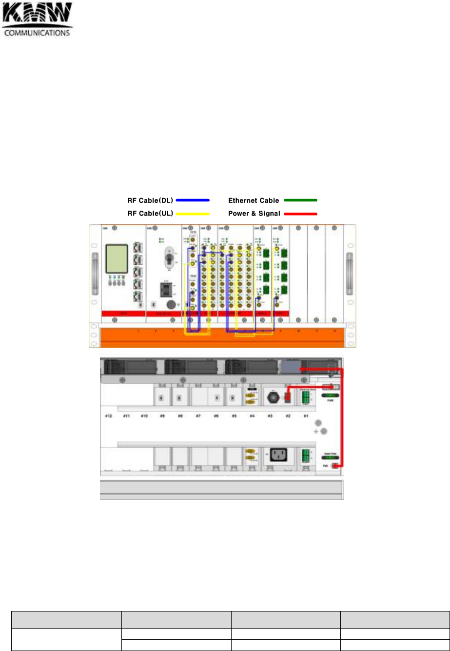
User Manual for POD Systems Revision: 0.7
© KMW USA Inc.
1818 E. Orangethrope Ave, Fullerton, CA 92831
Tel. +1 (714) 515-1100
www.kmwcomm.com
84
4.1.4 Cable Connection Example for Public Safety 700/800 band
POD DAS System configuration
- H-MCM : 1ea (or H-DMCU)
- H-PSM-OI: 1ea (or H-PSU)
- H-SRU: 1ea (H-SCM, H-FAU, H-CDU)
- H-FEM: 1ea (FEM-L-P7/P8)
- H-COM: 1ea
- H-DTM: 1ea
- H-HOM-L: 2ea
Figure 4-4 shows cable connection example for Public Safety 700/800 band.
Figure 4-4 Cable Connection Example for Public Safety 700/800 band
RF cable connection
- The RF ports for BTS connection are located in the back of H-SRU.
- All RF ports for the connection between modules installed in H-SRU are located in the front of H-SRU.
Optic cable connection
- The optic ports for the connection with Remote units are located in the front panel of H-HOM-L.
Power & signal cable connection
From
To
Comments
Power & Signal cable
H-PSM
H-SRU
H-SRU
H-FAU
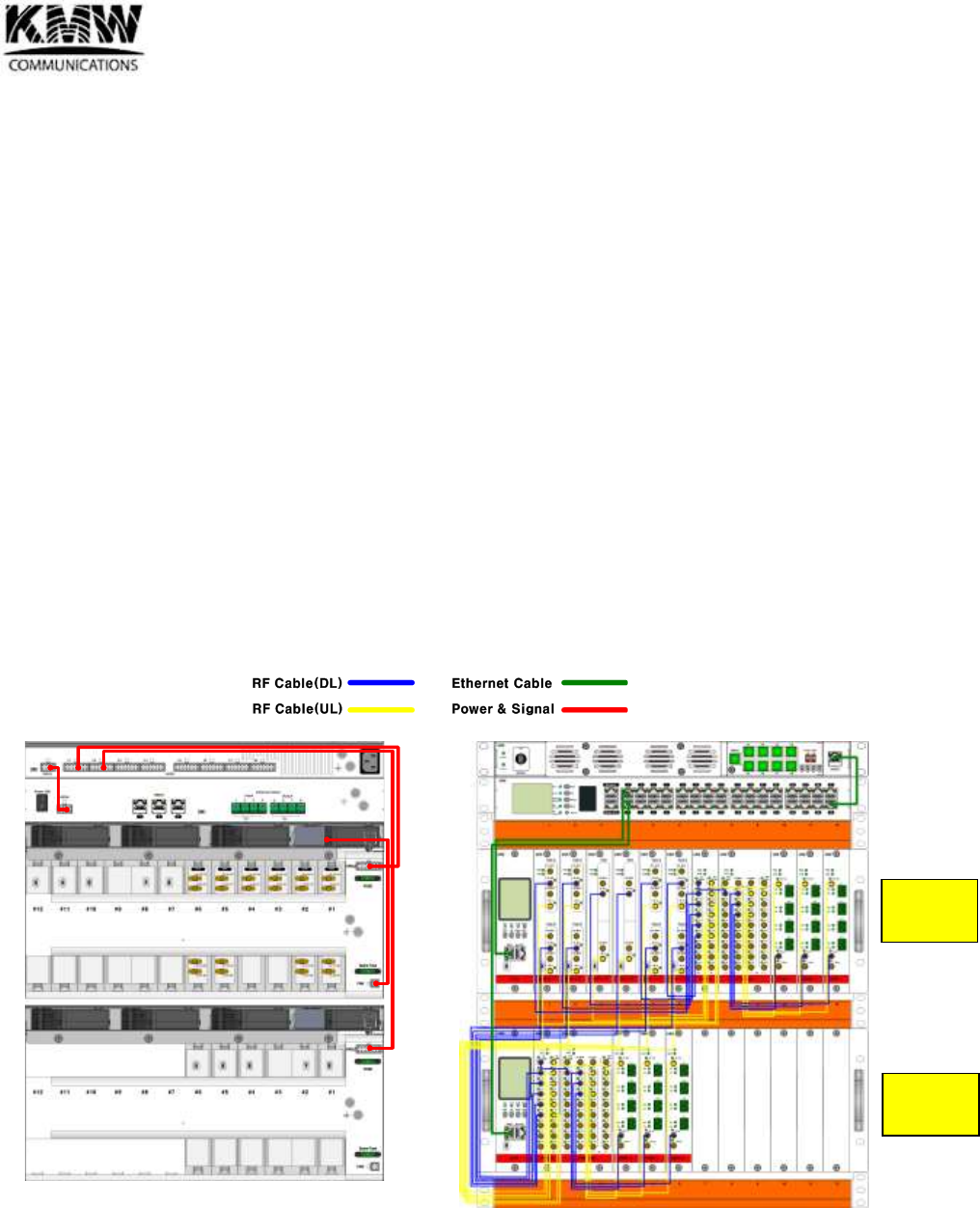
User Manual for POD Systems Revision: 0.7
© KMW USA Inc.
1818 E. Orangethrope Ave, Fullerton, CA 92831
Tel. +1 (714) 515-1100
www.kmwcomm.com
85
4.1.5 Cable Connection Example for MIMO configuration
POD DAS System configuration
- H-DMCU : 1ea
- H-PSU: 1ea
- H-SRU: 2ea (H-SCM, H-FAU, H-CDU)
- H-FEM: 6ea (H-FEM-L-7, H-FEM-L-C, H-FEM-L-P x2, H-FEM-L-A, H-FEM-L-W)
H-FEM-L-7, H-FEM-L-C, H-FEM-L-A, and H-FEM-L-W can support MIMO configuration by using one H-
FEM-L module because they have two paths in one module.
H-FEM-L-P supports only one path in one module. 2 H-FEM-L-P are needed to support MIMO
configuration for PCS frequency band.
- H-COM: 1ea
- H-DTM: 1ea
- H-HOM-L: 3ea
Figure 4-5 shows cable connection example for MIMO configuration.
MIMO #1
- H-FEM-L-x in H-SRU #1
- H-COM, H-DTM, and H-HOM-L in H-SRU #1
MIMO #2
- H-FEM-L-x in H-SRU #1
- H-COM, H-DTM, and H-HOM-L in H-SRU #2
Figure 4-5 Cable Connection for FDD frequency band (MIMO) support
H-SRU #1
H-SRU #2

User Manual for POD Systems Revision: 0.7
© KMW USA Inc.
1818 E. Orangethrope Ave, Fullerton, CA 92831
Tel. +1 (714) 515-1100
www.kmwcomm.com
86
RF cable connection
- The RF ports for BTS connection are located in the back of H-SRU.
- All RF ports for the connection between modules installed in H-SRU are located in the front of H-SRU.
- RF cable connection For MIMO #1
H-FEM-L-x in H-SRU #1H-COM in H-SRU #1 H-DTM in H-SRU #1H-HOM-L in H-SRU #1
- RF cable connection For MIMO #2
H-FEM-L-x in H-SRU #1H-COM in H-SRU #2 H-DTM in H-SRU #2H-HOM-L in H-SRU #2
Optic cable connection
- The optic ports for the connection with Remote units are located in the front panel of H-HOM-L.
Ethernet cable connection
From
To
Comments
Ethernet cable
H-DMCU
H-SCM in H-SRU #1
H-DMCU
H-SCM in H-SRU #2
H-DMCU
H-PSU
Power & signal cable connection
From
To
Comments
Power & Signal cable
H-PSU
H-DMCU
H-PSU
H-SRU #1
H-PSU
H-SRU #2
H-SRU
H-FAU in H-SRU #1
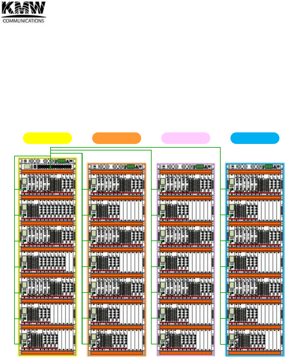
User Manual for POD Systems Revision: 0.7
© KMW USA Inc.
1818 E. Orangethrope Ave, Fullerton, CA 92831
Tel. +1 (714) 515-1100
www.kmwcomm.com
87
4.1.6 Cable connection between multiple Racks
Figure 4-6 shows how to connect cable and set rack ID for IP setting.
One H-DMCU is able to control and monitor maximum up to 4 racks and one rack can be composed of
maximum 7 H-SRUs and one H-DMCU. All H-PSU, H-SCM, and H-MCM are connected to H-DMCU through 32
Ethernet ports located in front side of H-DMCU.
Rack ID can be set by dip switch in H-PSU.
- Refer to section 2.1.12.7 to figure out how to set Rack ID.
It might need longer RF cable than RF cable with 35”length included in the packaged box for the connection
between racks. In this case, user needs to buy extra cable with longer length in advance. For your information,
RF cable with 60”, and 90” length can be provided by user’s special order.
Figure 4-6 Connection Diagram for Rack Inter Connection
Rack ID : #3Rack ID : #1 Rack ID : #4Rack ID : #2
Sub-Rack
#1
Sub-Rack
#2
Sub-Rack
#3
Sub-Rack
#4
Sub-Rack
#5
Sub-Rack
#6
Sub-Rack
#7

User Manual for POD Systems Revision: 0.7
© KMW USA Inc.
1818 E. Orangethrope Ave, Fullerton, CA 92831
Tel. +1 (714) 515-1100
www.kmwcomm.com
88
4.2 Remote Unit Cable Connection
4.2.1 7/5/3 band & PS700/800 RU
4.2.1.1 Cable
Ethernet cable
- For web GUI connection or connection with expansion RU
Connector: RJ45, female
Length: 2m
AC or DC Power cable
- Length: 2m
GND Cable
- Length: 2m
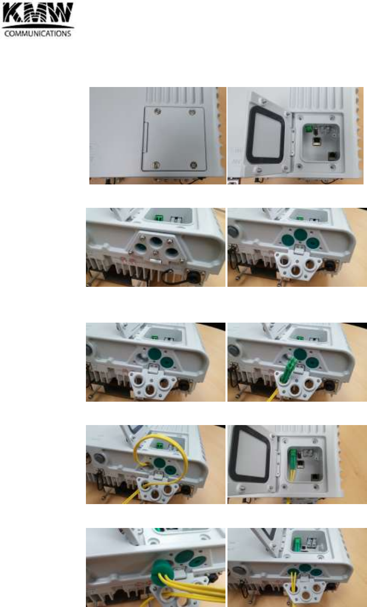
User Manual for POD Systems Revision: 0.7
© KMW USA Inc.
1818 E. Orangethrope Ave, Fullerton, CA 92831
Tel. +1 (714) 515-1100
www.kmwcomm.com
89
4.2.1.2 Optic cable connection
- After loosening 4x SECURITY SCREWS (M4), open the door for debug window.
- After loosening 5x SECURITY SCREWS (M4), open front door.
- After taking out of gasket from optic cable entrance located in left side, pass optic cable through this
entrance.
- Connect optic cable to optic port located on the left top side in debug window.
- Replace gasket into optic cable entrance.
- Continue in section 4.2.1.3.
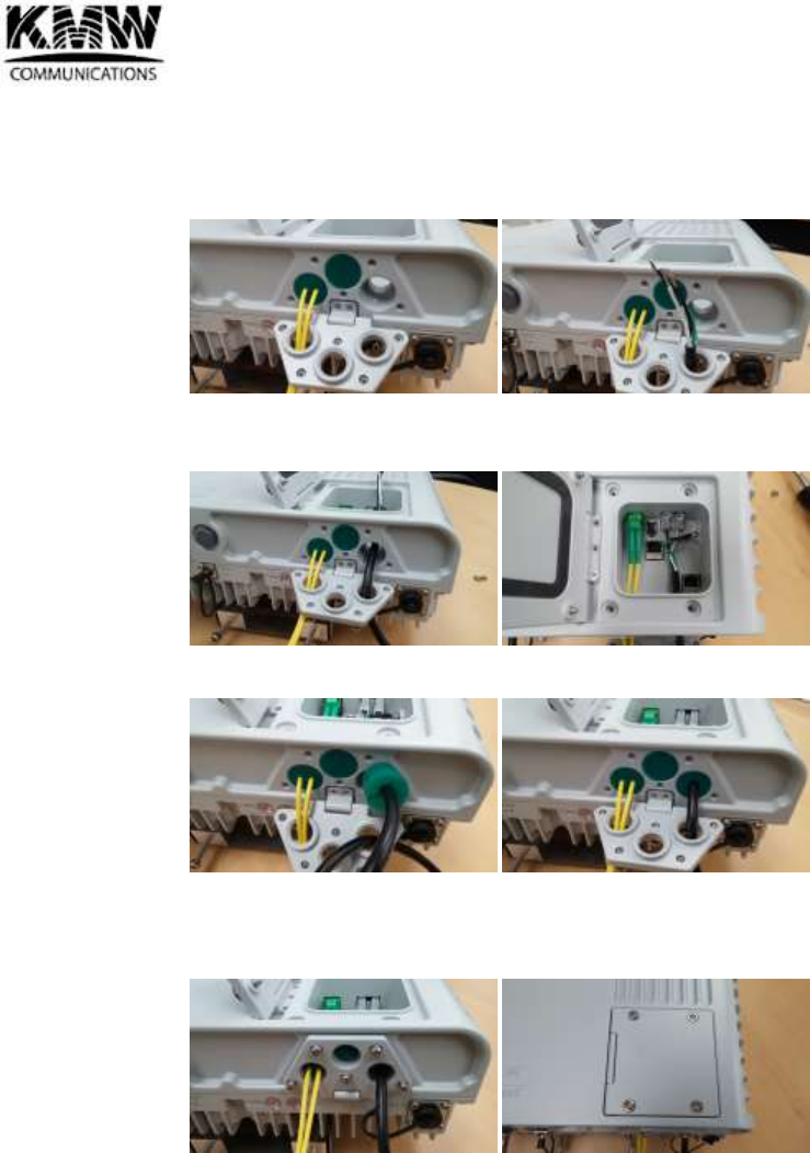
User Manual for POD Systems Revision: 0.7
© KMW USA Inc.
1818 E. Orangethrope Ave, Fullerton, CA 92831
Tel. +1 (714) 515-1100
www.kmwcomm.com
90
4.2.1.3 AC or DC power cable connection
- After taking out of gasket from power cable entrance located in right side, pass power cable through this
entrance.
- Connect power cable to AC (or DC) power terminal. In case of AC power cable, fasten ground cable by using
GND SCREW to GND position located on the right top side in debug window.
- Replace gasket into power cable entrance.
- If there is no expansion RU connected main RU, close/fasten the door for debug window and front door by
using SECURITY SCREWS (M4) and allowed Torque: 12.0 Kgfcm.
- If there is an expansion RU connected main RU, continue in section 4.2.1.4.
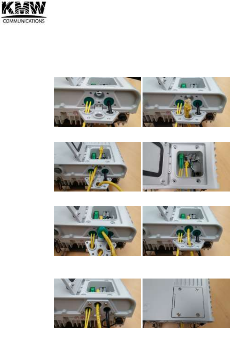
User Manual for POD Systems Revision: 0.7
© KMW USA Inc.
1818 E. Orangethrope Ave, Fullerton, CA 92831
Tel. +1 (714) 515-1100
www.kmwcomm.com
91
4.2.1.4 Ethernet cable connection for connecting with Expansion RU
If there is an expansion RU connected main RU, connect Ethernet cable with expansion RU before closing the
door for debug window and front door.
- After taking out of gasket from Ethernet cable entrance located in the middle, pass Ethernet cable through
this entrance.
- Connect Ethernet cable to EXT port (RJ 45).
- Replace gasket into Ethernet cable entrance.
- Close/fasten the door for debug window and front door by using SECURITY SCREWS (M4) and allowed
Torque: 12.0 Kgfcm.
- Connect the other side of Ethernet cable to EXT pot of expansion RU based on section 4.2.1.4.
CAUTION) The location of EXT pot in expansion RU is different from the location of EXT port in main RU. Make
sure where the location of EXT port in expansion RU is (refer to Figure 2-57) before connecting Ethernet cable to
expansion RU.

User Manual for POD Systems Revision: 0.7
© KMW USA Inc.
1818 E. Orangethrope Ave, Fullerton, CA 92831
Tel. +1 (714) 515-1100
www.kmwcomm.com
92
5. SPECIFICATION
5.1 Electrical Specifications (Low power HFM – Low power RU)
Table 5-1 POD DAS 2-Band RU Electrical Specifications (POD-R-P78-27-AC/DC)
Parameter
Specifications
Remark
PS 700
PS 800
Frequency
DL
758 - 775M
851 - 869M
UL
788 - 805M
806 - 824M
Input
DL
-40 ~ 20dBm
UL
-42dBm
-42dBm
Maximum
Output
DL
27dBm
@all temperature range
UL
-5dBm
@all temperature range
Gain Range
DL
7dB to 67dB
UL
-8dB to 37dB
Noise Figure @Max Gain
< 6 dB
@1 RU, optic loss: 0dB
Input/output Impedance
50 ohm
VSWR
< 1:1.7
System Delay
< 2us @2.6G, < 5us @other bands
Permitted optic loss
HOM-L: ~7.5dBo, HOM-H/OEM/OIM: ~10.5dBo
Frequency Error & EVM (LTE)
Frequency Error: <±0.01ppm, EVM: < 5%
Frequency Error & Rho (CDMA)
Frequency Error: <±0.05ppm, Rho: >0.912
Out of Band Emission
-13dBm/1KHz @9KHz – 150KHz
-13dBm/10KHz @150KHz – 30MHz
-13dBm/100KHz @30MHz – 1GHz
-13dBm/1MHz @1GHz – 12.75GHz
Operating Band
Unwanted
Emissions
CDMA
-45dBc/30KHz @±885KHz, -45dBc/30KHz @±1.125MHz
-50dBc/30KHz @±1.98MHz,
<-13dBm/30KHz @±2.25MHz, <-13dBm/1MHz @±4.0MHz
WCDMA/LTE
Meet 3GPP WCDMA/LTE Repeater Spec.
2 tone CW Test
Downlink: > 40dBc, Uplink: > 50dBc @two CW tone 1MHz separation
Operating
Temperature
Head-end
-10 ~ +50°C
RU
-40 ~ +55°C
Operating Humidity
≤ 95%, non-condensing
RU Enclosure
Meet IP65, NEMA4X

User Manual for POD Systems Revision: 0.7
© KMW USA Inc.
1818 E. Orangethrope Ave, Fullerton, CA 92831
Tel. +1 (714) 515-1100
www.kmwcomm.com
93
Table 5-2 POD DAS 7-Band RU Electrical Specifications (POD-R-7S8CPAWB-2730-AC/DC)
Parameter
Specifications
Remark
700M
SMR 800 +
850M
PCS
AWS
WCS
2.5G
Frequency
DL
728-756M
862 - 894M
1930-1995M
2110-2180M
2350-2360M
2496-2690M
UL
698-716M
777-787M
817 - 849M
1850-1915M
1710-1780M
2305-2315M
2496-2690M
Input
DL
-15 ~ 20dBm
UL
-42dBm
-45dBm
Maximum
Output
DL
27dBm
30dBm
@all temperature range
UL
-5dBm
@all temperature range
Gain Range
DL
7dB to 42dB
10dB to 45dB
UL
-8dB to 37dB
-5dB to 40dB
Noise Figure @Max Gain
< 6 dB
@1 RU, optic loss: 0dB
Input/output Impedance
50 ohm
VSWR
< 1:1.7
System Delay
< 2us @2.6G, < 5us @other bands
Permitted optic loss
HOM-L: ~7.5dBo, HOM-H/OEM/OIM: ~10.5dBo
Frequency Error & EVM (LTE)
Frequency Error: <±0.01ppm, EVM: < 5%
Frequency Error & Rho (CDMA)
Frequency Error: <±0.05ppm, Rho: >0.912
Out of Band Emission
-13dBm/1KHz @9KHz – 150KHz
-13dBm/10KHz @150KHz – 30MHz
-13dBm/100KHz @30MHz – 1GHz
-13dBm/1MHz @1GHz – 12.75GHz
Operating Band
Unwanted Emissions
CDMA
-45dBc/30KHz @±885KHz, -45dBc/30KHz @±1.125MHz, -50dBc/30KHz @±1.98MHz
<-13dBm/30KHz @±2.25MHz, <-13dBm/1MHz @±4.0MHz
WCDMA/LTE
Meet 3GPP WCDMA/LTE Repeater Spec.
2 tone CW Test
Downlink: > 40dBc, Uplink: > 50dBc @two CW tone 1MHz separation
Operating
Temperature
Head-end
-10 ~ +50°C
RU
-40 ~ +55°C
Operating Humidity
≤ 95%, non-condensing
RU Enclosure
Meet IP65, NEMA4X

User Manual for POD Systems Revision: 0.7
© KMW USA Inc.
1818 E. Orangethrope Ave, Fullerton, CA 92831
Tel. +1 (714) 515-1100
www.kmwcomm.com
94
5.2 Additional Model Names
Each 2-Band and 7-Band RU has several additional models from the basic model. They are identical to basic model except only with blocked RF band(s) by
Factory loaded software and without hardware changing. So Basic model supports up to specified number of bands and additional models supports less number
of bands with several blocked RF band(s).
The table shown in below shows the basic model and additional models which are derived from the basic model.
Table 5-3 Basic Model and Additional Models on 2-Band Remote Unit
Basic Model
Additional Model
Activated RF Band
Blocked RF band
POD-R-P78-27-AC
-
PS 700M, PS 800M
N/A
POD-R-P7-27-AC
PS 700M
PS 800M
POD-R-P8-27-AC
PS 800M
PS 700M
Table 5-4 Basic Model and Additional Models on 7-Band Remote Unit
Basic Model
Additional Model
Activated RF Band
Blocked RF band
POD-R-7S8CPAWB-2730-AC
-
LTE 700M, SMR 800M, Cellular 850M, PCS 1.9G,
AWS 2.1G, WCS 2.3G, BRS 2.5G
N/A
POD-R-7S8CPAW-2730-AC
LTE 700M, SMR 800M, Cellular 850M, PCS 1.9G,
AWS 2.1G, WCS 2.3G
BRS 2.5G
POD-R-7CPAWB-2730-AC
LTE 700M, Cellular 850M, PCS 1.9G, AWS 2.1G,
WCS 2.3G, BRS 2.5G
SMR 800M
POD-R-7CPAW-2730-AC
LTE 700M, Cellular 850M, PCS 1.9G, AWS 2.1G,
WCS 2.3G
SMR 800M, BRS 2.5G
POD-R-7CPA-2730-AC
LTE 700M, Cellular 850M, PCS 1.9G, AWS 2.1G,
SMR 800M, WCS 2.3G, BRS 2.5G
POD-R-7PA-2730-AC
LTE 700M, PCS 1.9G, AWS 2.1G
SMR 800M, Cellular 850M, WCS 2.3G, BRS 2.5G
POD-R-CPA-2730-AC
Cellular 850M, PCS 1.9G, AWS 2.1G
LTE 700M, SMR 800M, WCS 2.3G, BRS 2.5G
POD-R-7CP-2730-AC
LTE 700M, Cellular 850M, PCS 1.9G
SMR 800M, AWS 2.1G, WCS 2.3G, BRS 2.5G
POD-R-S8PB-2730-AC
SMR 800M, PCS 1.9G, BRS 2.5G
LTE 700M, Cellular 850M, AWS 2.1G, WCS 2.3G,