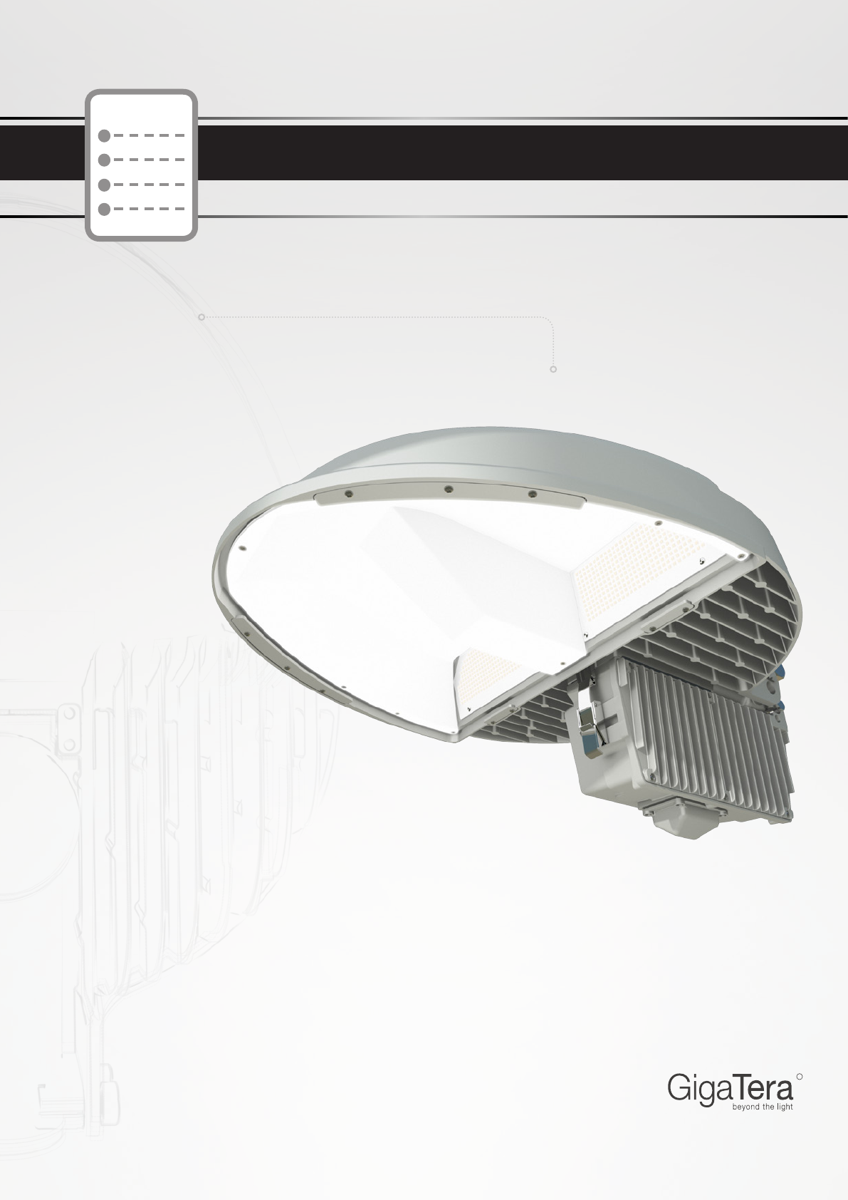
User Manual
HR
R
85W | 110W | 150W
Product Installation & Operation User Guide
http://www.kmwgigatera.com
Installation & Operation User Guide
Roadway Lighting
LED
Serious injury might result if the following precautions are not followed.
The user may be injured or there would be property damage if the instructions below are not followed.
• The installation should be performed by certied workers under the relevant regulations of end user's
country / region.
• Never modify or disassemble LED lighting arbitrarily because it can cause serious accidents.
• Never use any input power except the listed rated voltage. If not, it can cause serious accidents.
• Before installation, shut off the power supply and verify it is de-powered using a measuring instrument.
• The wiring should be insulated under end user's respective region's Electric Installations Standards.
• Do not install in a wet environment.
This symbol is intended to remind the user the presence of actions and operation that may cause danger.
Please read instructions carefully and follow the instructions to avoid any danger.
This symbol is intended to represent precautions that the user should follow to prevent danger.
• Do not forcefully pull on AC/DC lines when wiring up the lighting. (It causes the wires to snap.)
• Do not use this product for any purposes other than what’s specied.
The manufacturer or sellers are not responsible for breakdowns or accidents caused by its improper use.
• When connecting the wires, use proper connection terminals depending on the site of installation.
Do not install in a wet environment.
• Make sure to ground xture by contacting it to metals around it to prevent damage by static.
• The product may be damaged if static is not removed.
• During the operation, be careful not to disconnect the wires.
• Make sure the grounding is performed under Electricity Standards.
• Using it for any voltage other than specied can cause failure or re.
• Do not use it in moist environment.
• Be mindful of proper ventilation of product.
• Improper installation or disassembly causes a deformation or breakdown of the product.
• Consider proper protection devices, such as circuit breakers, fuses, switches, etc. for safety precautions.
• Do not install in an enviroment with excessive vibration.
• Do not handle product with contaminated hands or gloves.
• In any event, do not store / install in a contaminated place.
• Changes or modications not expressly approved by the manufacturer could void the user's authority to
operate the equipment.
• This equipment has been tested and found to comply with the limits for a Class B digital device, pursuant
to Part 15 of the FCC Rules. These limits are designed to provide reasonable protection against harmful
interference in a residential installation. This equipment generates, uses and can radiate radio frequency
energy and, if not installed and used in accordance with the instructions, may cause harmful interference
to radio communications. However, there is no guarantee that interference will not occur in a particular
installation.
• If this equipment does cause harmful interference to radio or television reception, which can be
determined by turning the equipment off and on, the user is encouraged to try to correct the interference
by one or more of the following measures:
- Reorient or relocate the receiving antenna.
- Increase the separation between the equipment and receiver.
- Connect the equipment into an outlet on a circuit different from that to which the receiver is connected.
- Consult the dealer or an experienced radio/TV technician for help.
WARNING
CAUTION
『Safety Precautions Installation』
The information in this document is subject to change without notice
Copyright 1991 ~ 2012 KMW, INC. All Rights Reserved
©
3
Document Revision V0.61 2013.01.11 Pages
R
Street Light (HR) Installation & Operation User Guide
Product OverviewProduct Features
1) Scope Overview
This manual describes how to compose, install, and operate LED streetlamps.
2) LED Streetlight Apparatus
A streetlight is a light that is installed on the side of least four-lane roads to improve trafc safety of vehicles
and civilians as well as trafc efciency.
3) Usage
This is a trafc safety facility not only for expressways, streets, parking lots, and industrial facilities, but also
for the safety on motorways or sidewalks. It is roughly divided into road lamps, sidewalk lamps, overbridge
lamps, and high-mast lightings. The shape varies with the road feature and the beauty concept of your city
to give you a lot of choices.
The HR product lineup is 85W, 110W, 150W and all of them are proud of their high lamp efciency over
100 lm/W. The lamp efciencies are 8,500 lm, 11,000 lm, and 15,000 lm, respectively.
The light distribution type is diversied. It supports Type II-S, Type II-M, Type III-S, Type-III-M to enable
streetlamp installation in all environments.
1) Vertically Arranged LED Module Method
HR adopted vertically arranged LED moduled unlike existing streetlamps. The vertically arranged LED mod-
ules can help to minimize the heat generating from the LED and further guarantee long life of the device in
the long run.
2) An Electronic Auto Switch Is Attached
On top of a product is installed an electronic Auto Switch. When the intensity of illumination reaches a certain
level, the lamp will be automatically turned off rst and then it will be automatically turned off while it is not
securing an illumination with sufcient intensity. In other words, it is a very convenient function to automati-
cally turn on or off the lamp without operating the switch whenever necessary.
3) Converter (SMPS) Exchange without Tools
HR adopted the Locking Lactch type to the locking device in the SMPS enclosure part to open or close the
enclosure without any tool when you are exchanging the SMPS. In addition, the internal SMPS is xed not
by bolts but not sockets for more comfortable maintenance.
4) Silver Nanoreflecting Plate
A nanoreflecting plate is expected to make effect on raising the intensity of illumination, i.e., improving the brightness
when it is used for illumination. Although we install a lamp with lower wattage than those of the other companies, we
can realize the intensity of illumination equivalent to or higher than them, eventually with more outstanding electricity-
saving effect.
The information in this document is subject to change without notice
Copyright 1991 ~ 2012 KMW, INC. All Rights Reserved
©
4
Document Revision V0.61 2013.01.11 Pages
R
Street Light (HR) Installation & Operation User Guide
Precautions before Installation
Precautions before Installation
This installation manual is based on the assumption an Electronic Auto Switch is installed to each product.
A product with an Electronic Auto Switch may look different from what it looks like in the brochure. Although, the other
parts than the Electronic Auto Switch will be installed in the same manner.
The whole HR lineup will be delivered without AC cables.
The AC power cables shall be purchased at the cost of the user but we would like to recommend the cables with the
following specifications.
AC Power Cable Specification: SJTW Outdoor Power Cable
The information in this document is subject to change without notice
Copyright 1991 ~ 2012 KMW, INC. All Rights Reserved
©
5
Document Revision V0.61 2013.01.11 Pages
R
Street Light (HR) Installation & Operation User Guide
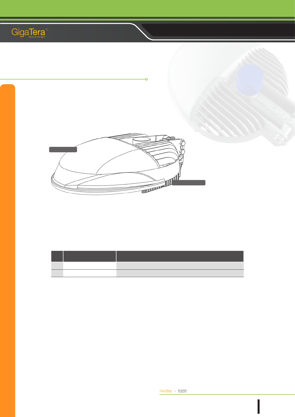
①
HR
②
Converter
Detail Description
No Item Purpose
① HR
LED Streetlight
② Converter
Lamp and Brightness Sensor Power Supply Device (SMPS)
Package 1 (Standard Type)
The information in this document is subject to change without notice
Copyright 1991 ~ 2012 KMW, INC. All Rights Reserved
©
6
Document Revision V0.61 2013.01.11 Pages
R
Street Light (HR) Installation & Operation User Guide
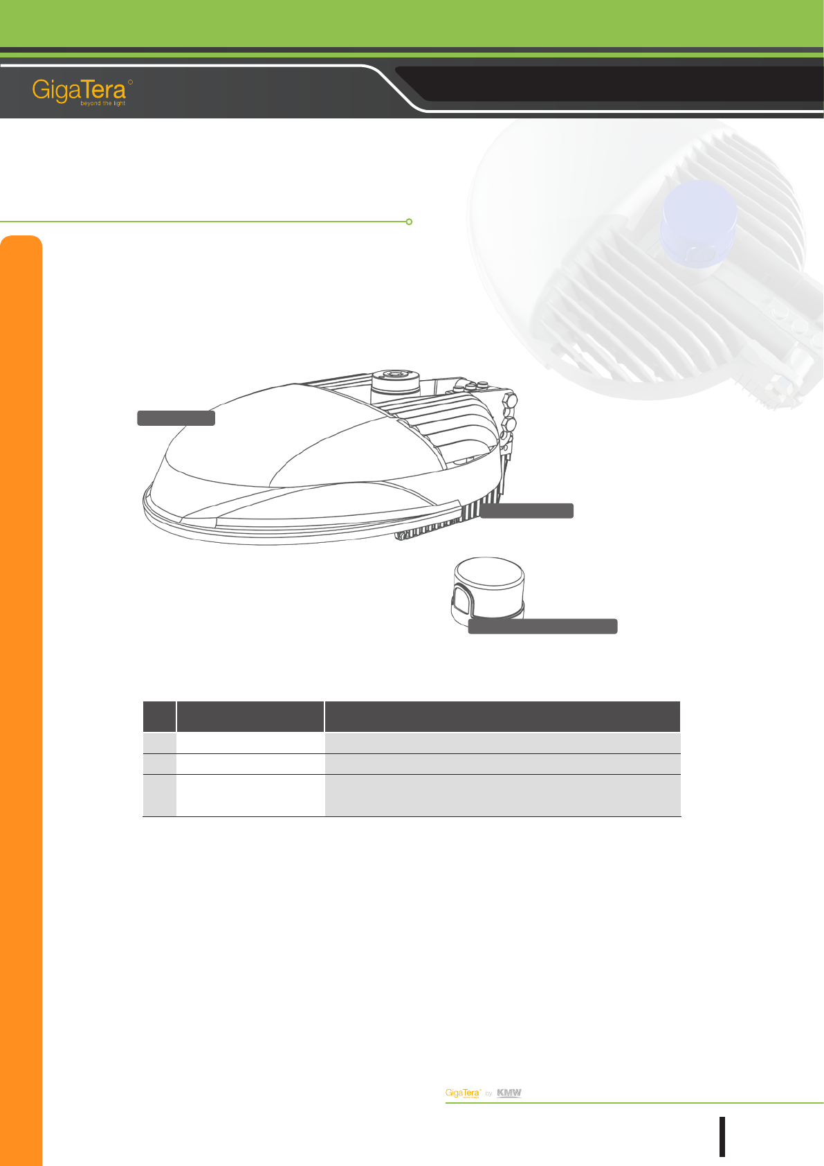
③ Illumination Sensor Intensity
Detail Description
No Item Purpose
① HR
LED Streetlight
② Converter
Lamp and Brightness Sensor Power Supply Device (SMPS)
③Illumination Sensor In-
tensity
Surrounding Brightness Based Automatic Power On/Off Function (Photo
Sensor)
Package 2 (Brightness Sending Type)
①
HR
②
Converter
The information in this document is subject to change without notice
Copyright 1991 ~ 2012 KMW, INC. All Rights Reserved
©
7
Document Revision V0.61 2013.01.11 Pages
R
Street Light (HR) Installation & Operation User Guide
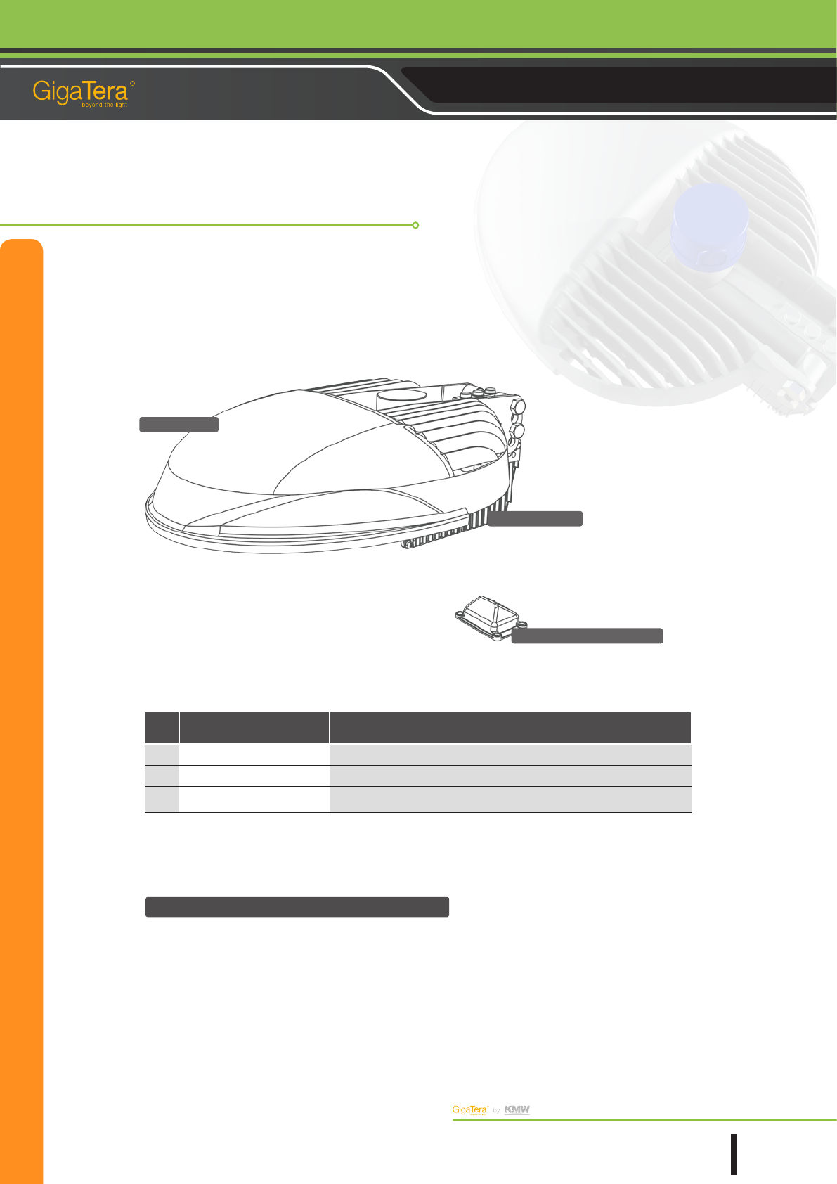
①
HR
③ DCM
②
Converter
Package 3 (Built-In DCM Type)
Dimming Control
Once installed, the DCM module will be synchronized with the LCS system (for illumination control) to enable the
dimming control from Zigbee.
Detail Description
No Item Purpose
① HR
LED Streetlight
② Converter
Lamp and Brightness Sensor Power Supply Device (SMPS)
③ DCM Data Control Module (*LCS Controller is not included.)
The information in this document is subject to change without notice
Copyright 1991 ~ 2012 KMW, INC. All Rights Reserved
©
8
Document Revision V0.61 2013.01.11 Pages
R
Street Light (HR) Installation & Operation User Guide
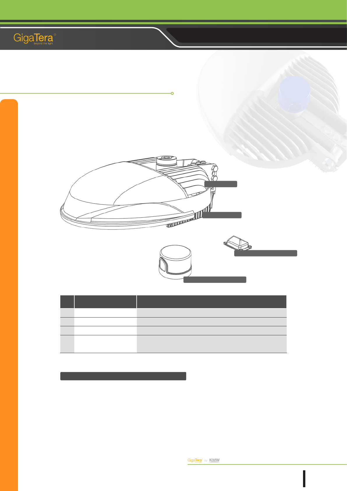
③ Illumination Sensor Intensity
②
Converter
Detail Description
No Item Purpose
① HR
LED Streetlight
② Converter
LED Streetlight
③ DCM
LED Streetlight
④Illumination Sensor In-
tensity
LED Streetlight
Package 4 (Package Type)
Dimming Control
Once installed, the DCM module will be synchronized with the LCS system (for illumination control) to enable the
dimming control from Zigbee.
④
DCM
①
HR
The information in this document is subject to change without notice
Copyright 1991 ~ 2012 KMW, INC. All Rights Reserved
©
9
Document Revision V0.61 2013.01.11 Pages
R
Street Light (HR) Installation & Operation User Guide
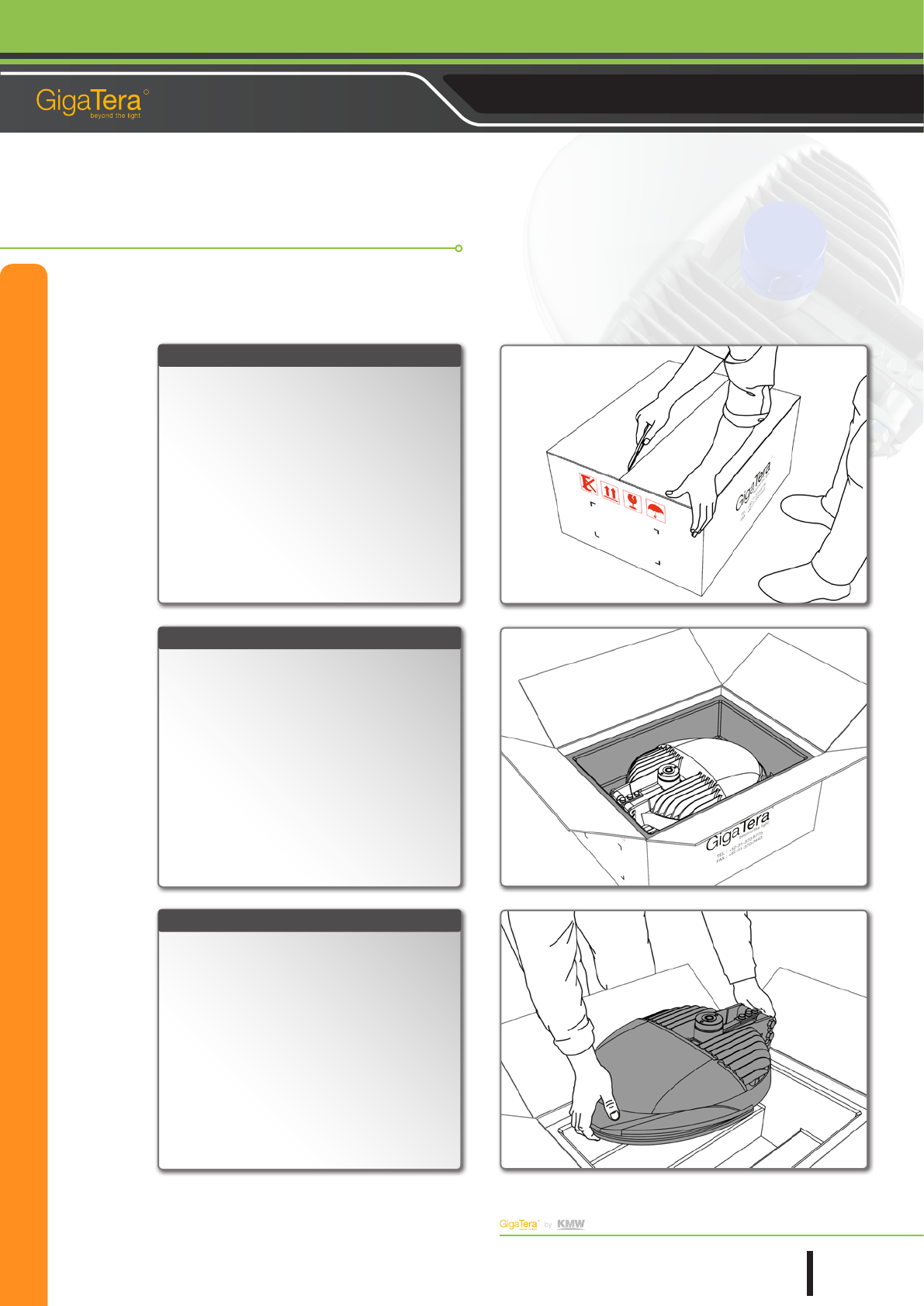
Put the product box on an even and at surface and
cut the box along the suture line with a cutter.
Please make sure the cutter blade doesn't enter
deep enough to scratch the product surface. Also,
be careful not to hurt yourself.
Once the box is open, you will see a package fully
covering the product.
Open the top of the box wide in four directions and
remove the product package and you will see the top
surface of the product.
This product is somewhat bit heavy, weighing 10 Kg.
It is recommended to use both of your hands to put
the product out of the box. Hold it with your palms
for safety.
STEP. 01
STEP. 02
STEP. 03
Open the Product
The information in this document is subject to change without notice
Copyright 1991 ~ 2012 KMW, INC. All Rights Reserved
©
10
Document Revision V0.61 2013.01.11 Pages
R
Street Light (HR) Installation & Operation User Guide
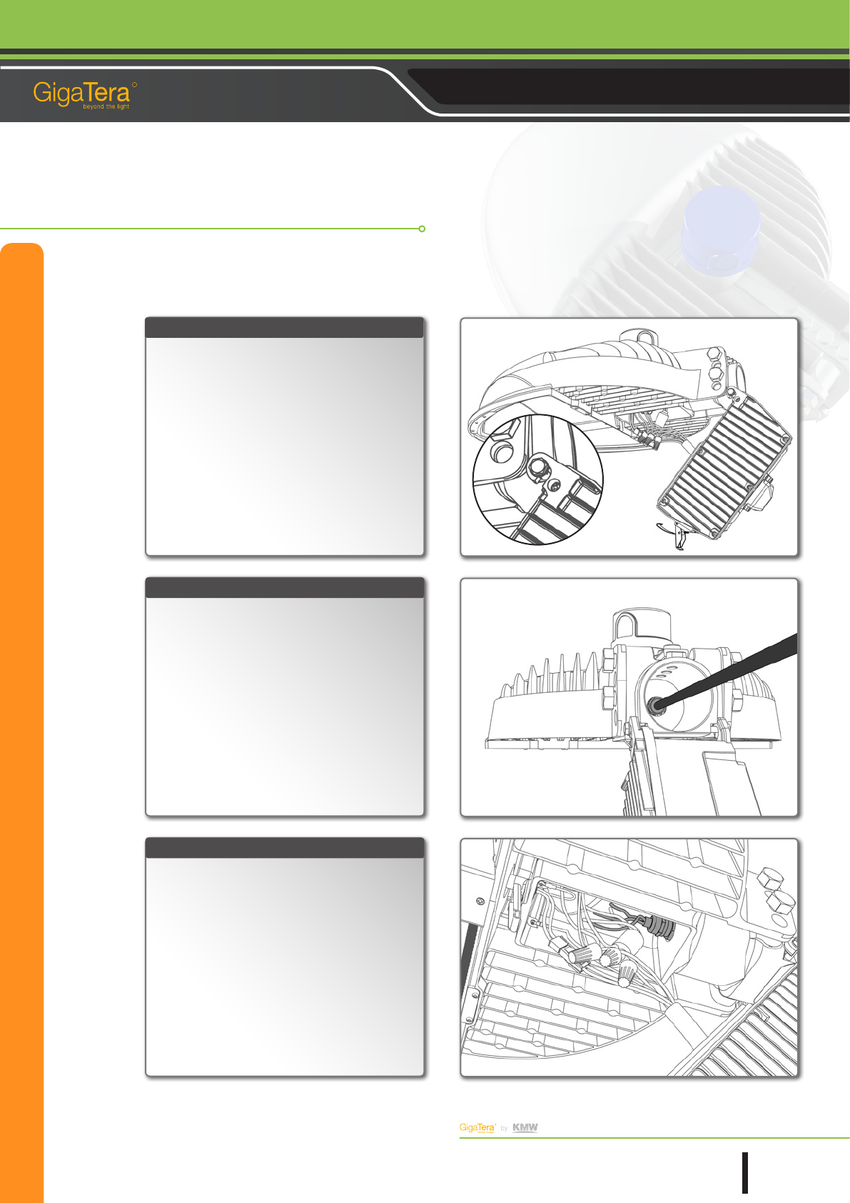
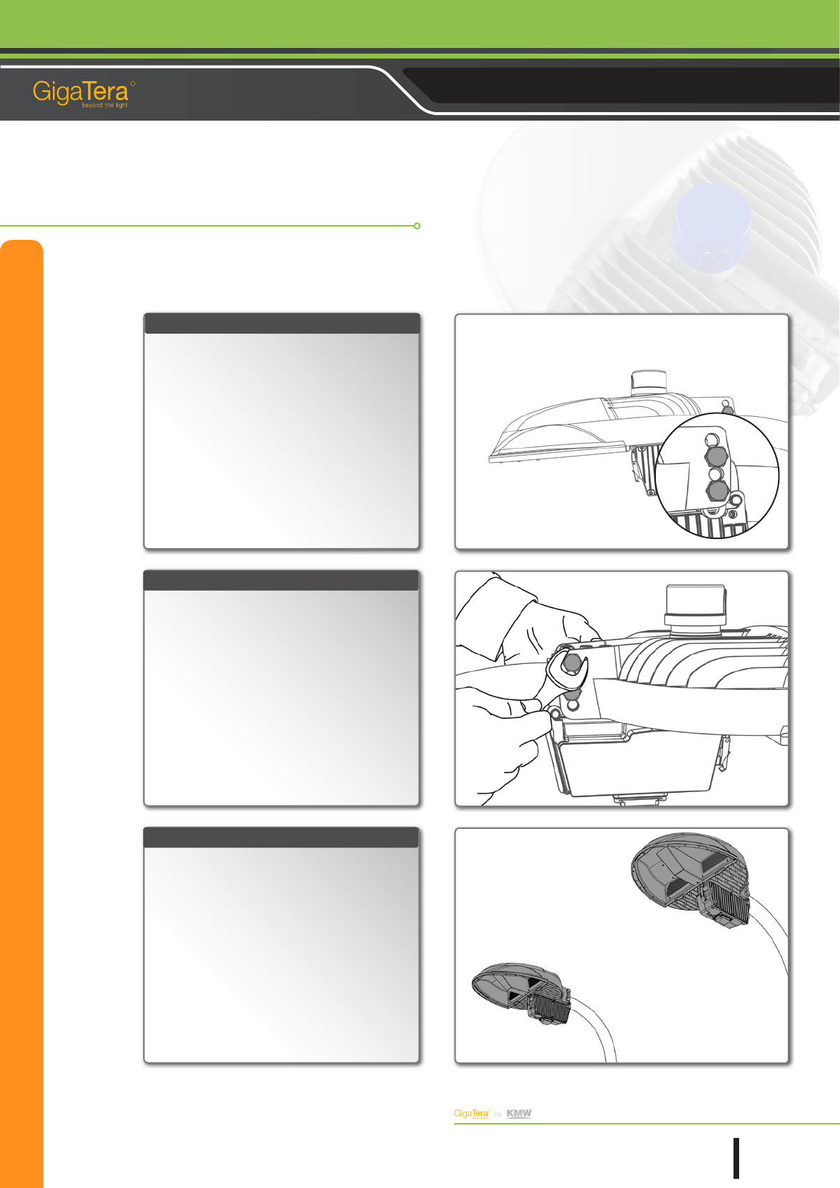
As the sun rises from the east and sets to the west,
you must direct the Brightness Sensor Receptacle to
the north for normal operation of the product.
To begin with, use a driver to loosen both bolts like
the following gure:
If you don't use the Electronic Auto Switch, skip the
above step and jump to Step 10.
Swing the receptacle horizontally and set it as close
as to the north on the basis of the arrow (north)
marked on top. Be sure to align the receptacle bolt
holes with those of the apparatus to bond them with
xing bolts.
There are several bolt xing holes at the bottom of
the receptacle.
Direct the receptacle to the north and tighten two
bolts in the reverse order of the disassembly until the
connector is xed to the apparatus.
STEP. 04
STEP. 05
STEP. 06
Brightness Sensor Socket Direction Control (Option)
Bolt holes
The information in this document is subject to change without notice
Copyright 1991 ~ 2012 KMW, INC. All Rights Reserved
©
11
Document Revision V0.61 2013.01.11 Pages
R
Street Light (HR) Installation & Operation User Guide
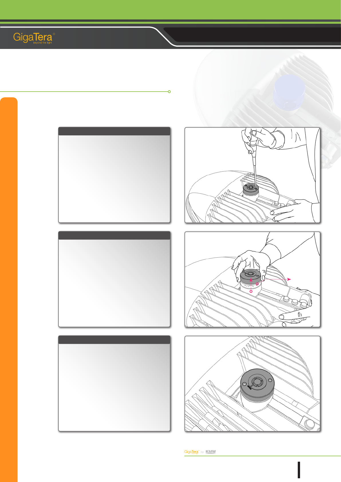
The brightness sensor has a directional nature as
seen in the following gure:
Among the three connection parts, one is designed
to be long and wide and the others short and narrow.
Please remember that forced installation against the
direction nature may damage the lamp connection
part.
The brightness sensor is optional and it may look
different from what it looks like in the gure if it is
bought by the user.
Align the brightness sensor with the lamp for con-
nection and impose little force downward until they
are tightly bonded.
Turn the brightness sensor clockwise while pushing
it inside.
If you complete the above procedure without fail,
the Electronic Auto Switch will keep rotating until it
is xed to the lamp connection part like the follow-
ing gure:
STEP. 07
STEP. 08
STEP. 09
Illumination Sensor Intensity Installation (Option)
Clockwise
The information in this document is subject to change without notice
Copyright 1991 ~ 2012 KMW, INC. All Rights Reserved
©
12
Document Revision V0.61 2013.01.11 Pages
R
Street Light (HR) Installation & Operation User Guide
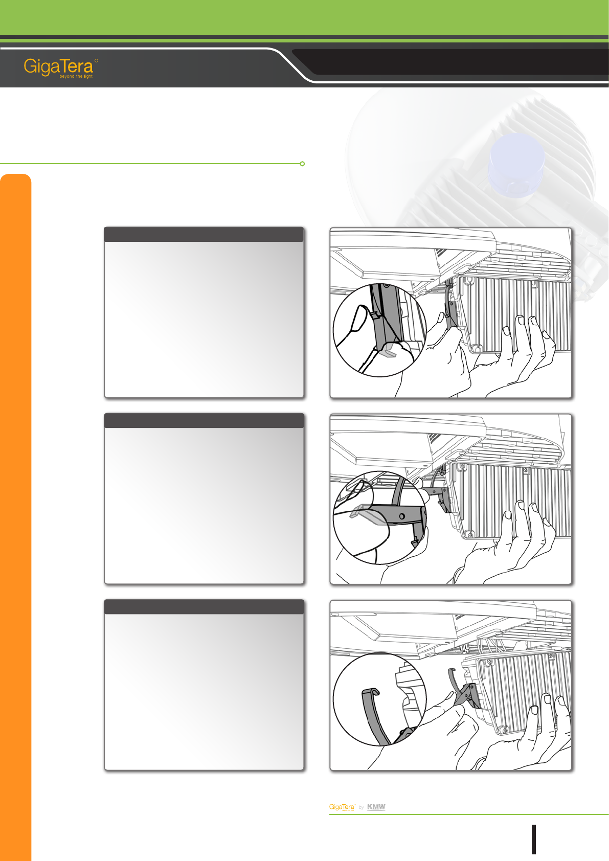
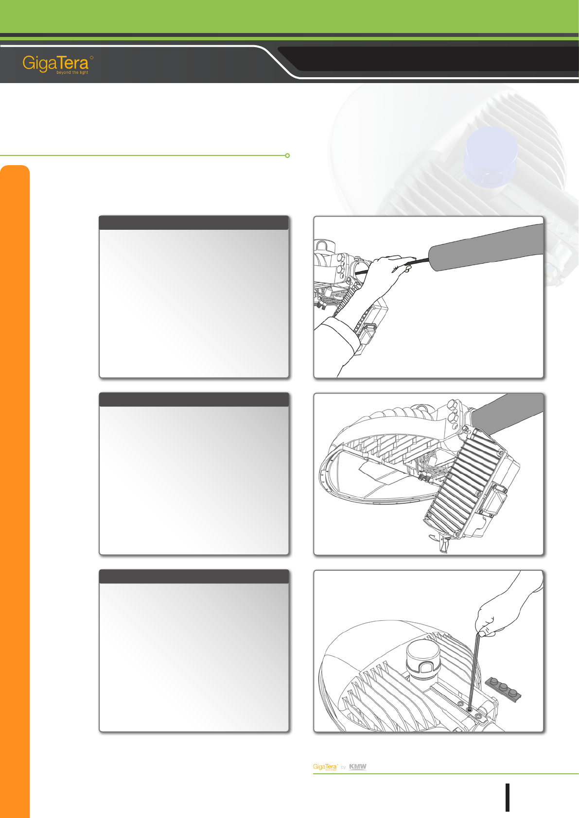
Open the SMPS part from the main body for AC pow-
er cable wiring.
To begin with, use your thumb to push the latch lock-
er upward and pull the lower part like the following
gure:
When you zoom in the image, the part that was hid-
den for easier description purpose will appear
Bend up vled part like the following gure:
When you zoom in the image, the part that was hid-
den for easier description purpose will appear
Unlock the latched part and open the SMPS main
body.
STEP. 10
STEP. 11
STEP. 12
Open the Converter
The information in this document is subject to change without notice
Copyright 1991 ~ 2012 KMW, INC. All Rights Reserved
©
13
Document Revision V0.61 2013.01.11 Pages
R
Street Light (HR) Installation & Operation User Guide
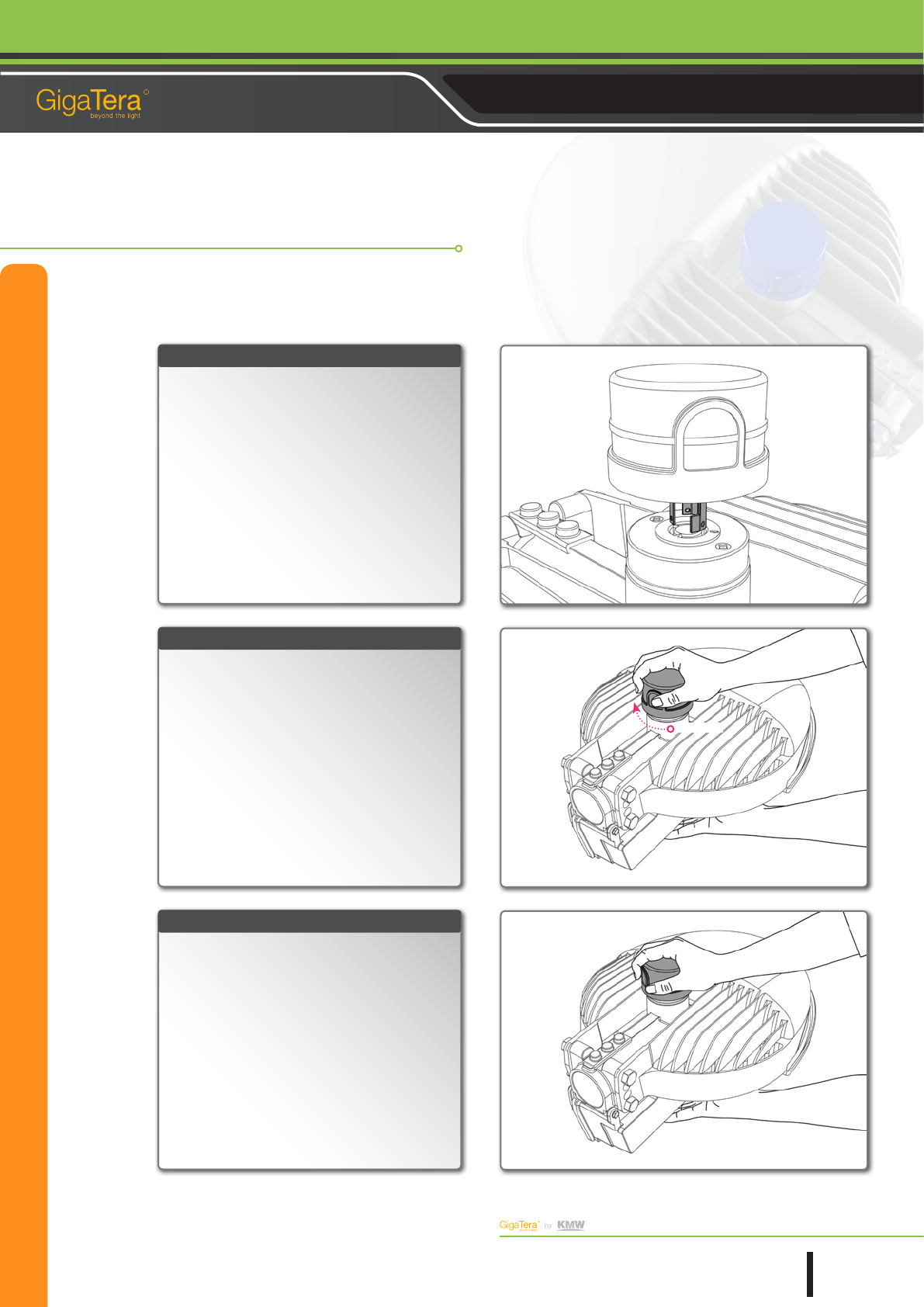
Open the SMPS part and hang it on the hook before
you start wiring.
Insert the AC power cable behind the arm like the fol-
lowing gure:
HR Model basically does not supply the AC power
cable. If necessary, it shall be purchased by the user.
Once the AC power cable moved inside the lamp,
tension it with a margin for later connection with the
twister.
STEP. 13
STEP. 14
STEP. 15
AC Power Cable Wiring
The information in this document is subject to change without notice
Copyright 1991 ~ 2012 KMW, INC. All Rights Reserved
©
14
Document Revision V0.61 2013.01.11 Pages
R
Street Light (HR) Installation & Operation User Guide
Keep the lamp and the light pole so arranged that
the AC power cable is not stuck between them be-
fore you bond them together.
Attach the lamp to the light pole like the fol-
lowing gure:
Once the lamp is installed, use xing bolts to x it to
the light pole.
When you remove the cap on top of the lamp as il-
lustrated in the gure, you will see three lamp xing
nuts called M10 Set Screw (Mood Bolt) inside.
Use a hexagonal wrench to tighten the xing bolts
until the lamp is tightly bonded with the light pole.
Once the xing bolts are in their positions, recover
the top with the cap.
STEP. 16
STEP. 17
STEP. 18
Light Installation
The information in this document is subject to change without notice
Copyright 1991 ~ 2012 KMW, INC. All Rights Reserved
©
15
Document Revision V0.61 2013.01.11 Pages
R
Street Light (HR) Installation & Operation User Guide
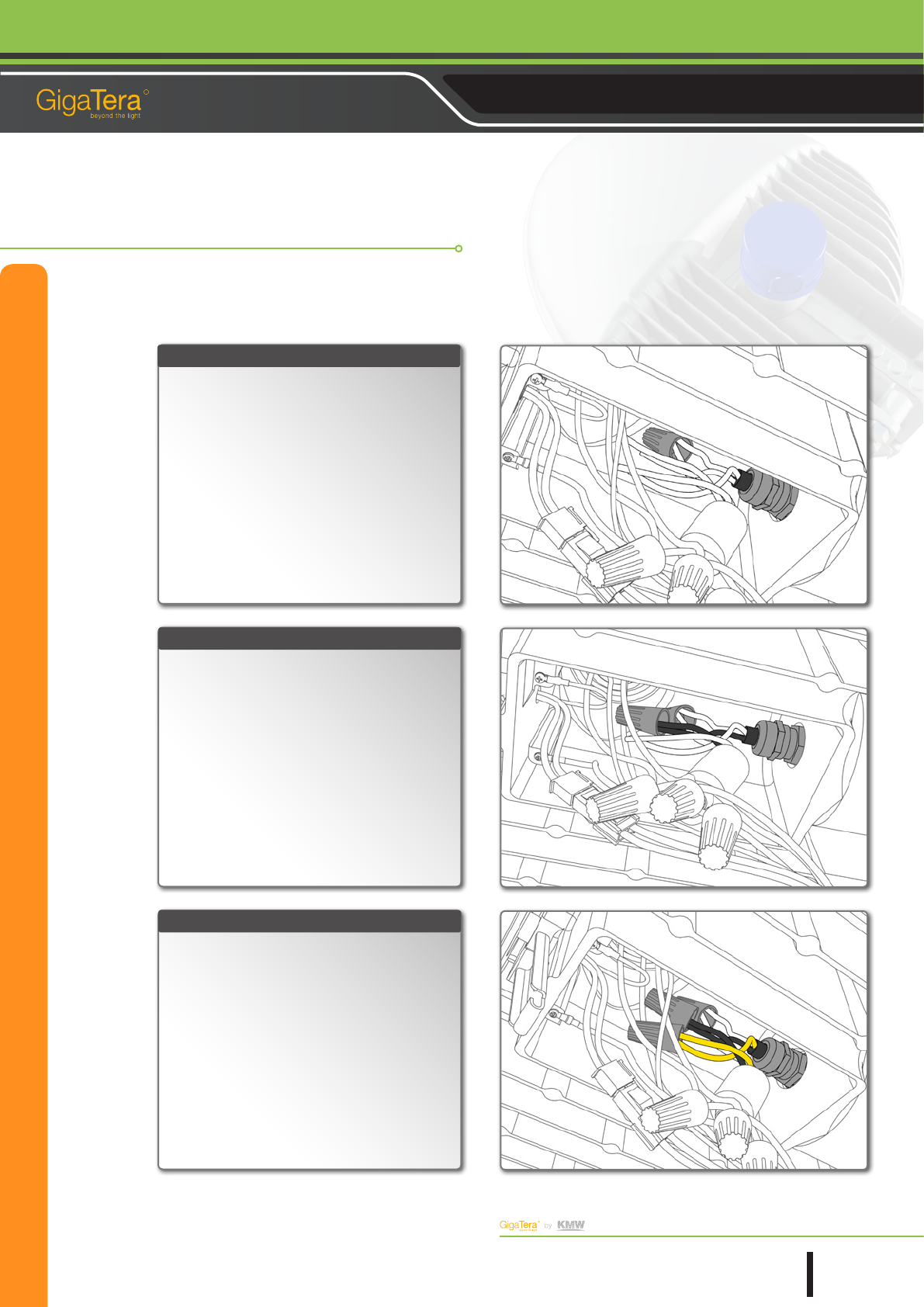
Be sure to bond the AC power cable with the SMPS
cable. At rst, use the twister to connect the two
cores of the white cable (N) with each other.
Each cable comes from the core after it is connected
to the AC power cable and the lamp body.
Be sure to use only the cable in the same color for
power cable connection. Wrong wiring may give a criti-
cal damage to the product at the time of power supply.
Use the twister to connect the two cores of the black
cable (N) with each other like the following gure:
Each cable comes from the core after it is connected
to the AC power cable and the lamp body.
Be sure to use only the cable in the same color for
power cable connection. Wrong wiring may give a criti-
cal damage to the product at the time of power supply.
Use the twister to connect two cores of a yellowish
green and yellow mixture cable (FG) with each other.
Each cable comes from the core after it is connected
to the AC power cable and the lamp body.
Be sure to use only the cable in the same color for
power cable connection. Wrong wiring may give a criti-
cal damage to the product at the time of power supply.
STEP. 19
STEP. 20
STEP. 21
AC cable Connection
The information in this document is subject to change without notice
Copyright 1991 ~ 2012 KMW, INC. All Rights Reserved
©
16
Document Revision V0.61 2013.01.11 Pages
R
Street Light (HR) Installation & Operation User Guide
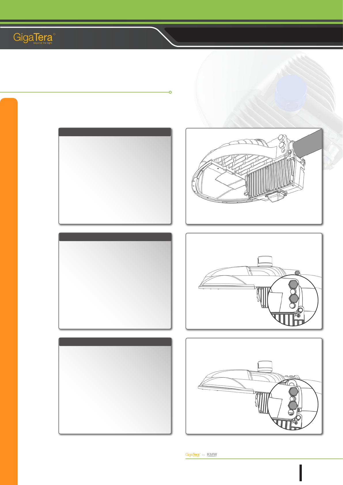
Once the AC power cable is connected, arrange the
internal wiring well and close the SMPS cover like the
following gure:
STEP. 22
Lamp Angle Control
This product is structured to control the lighting sur-
face by 5° in vertical direction.
Please remember the default of the product is set to 0°
when it is shipped out from the factory.
Do not disassemble the xing bolt for angle setting.
The lamp may rotate downward to damage the prod-
uct.
Remove the xing bolts in front to raise the lamp by
5°.
Push the lamp upward whiling aligning its second
and fourth bolt holes with the corresponding light
pole holes and bolt parts together for xing like the
following gure:
Put the bolts through the points where both holes
are aligned and tighten them rmly.
STEP. 23
STEP. 24
The information in this document is subject to change without notice
Copyright 1991 ~ 2012 KMW, INC. All Rights Reserved
©
17
Document Revision V0.61 2013.01.11 Pages
R
Street Light (HR) Installation & Operation User Guide
Remove the xing bolts in front to lower the lamp
by 5°.
Push the lamp downward whiling aligning its rst
and third bolt holes with the corresponding light
pole holes and bolt parts together for xing like the
following gure:
Put the bolts through the points where both holes
are aligned and tighten them rmly.
STEP. 25
Lamp Angle Control
Use a 17 mm spanner to tighten the xing bolts on
the lamp side. In this case, both sides shall be tight-
ened.
Now, HR Product installation is completed.
Turn the main power switch on to check if the prod-
uct is working properly.
STEP. 26
STEP. 27
RF & Microwave Products
The Global Leading RF & LED Provider
1521 E. Orangethorpe Ave., Ste. A Fullerton, CA 92831 U.S.A
183-6, Yeongcheon-ro, Dongtan-myeon, Hwaseong-si, Gyeonggi-do, Korea
+1.714.515.1100 sales@kmwgigatera.com
+82.31.370.8720 chriskim@kmw.co.kr
For America
For Non-America