KONICA MINOLTA A09N2 Authentication Unit User Manual Installation manual
KONICA MINOLTA, INC. Authentication Unit Installation manual
Contents
- 1. User Manual
- 2. User Manual_Installation manual
User Manual_Installation manual
E-1
AU-201S Authentication Unit
INSTALLATION MANUAL
A7AH-9622-00
Applied Machines: 367/287/227
MFP: 36 ppm/28 ppm/22 ppm
Product Code: A789/A7AH/A7AK
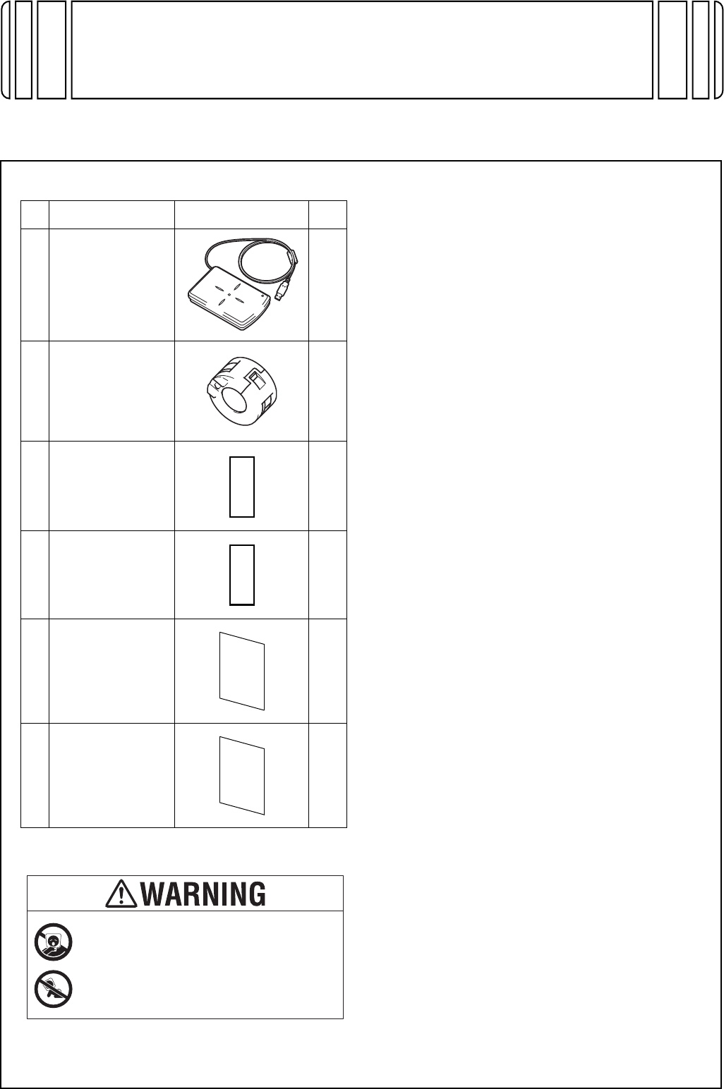
1. Accessory parts
* This part is not used in this installation.
Note:
• The following items are required to install this
product.
• Local Interface Kit EK-608
• Working Table WT-506
• When you attach this Authentication unit AU-
201S to the Working Table, we recommend you
attach this unit to the Working Table before you
attach the Working Table to the machine.
• When you use the Mount Kit to attach this
Authentication unit to the machine, see the
installation manual of Mount Kit for information
on the installation procedure.
• This manual provides the illustrations of the
accessory parts and machine that may be
slightly different in shape from yours. In that
case, instead of the illustrations, use the
appearance of your machine to follow the
installation procedure. This does not cause any
significant change or problem with the proce-
dure.
No. Name Shape Q’ty
1. Authentication
unit
1
2. Ferrite core
1
3. Hook-and-loop
fastener A
(hook)
(25.4 x 10 mm)*
3
4. Hook-and-loop
fastener B
(loop)
(25.4 x 10 mm)*
3
5. Safety
information
guide 1
set
6. Additional
information
1
set
Keep this bag away from babies and
children. Do not use in cribs, beds,
carriages, or playpens.
The thin film may cling to nose and
mouth and prevent breathing. This bag is
not a toy.
E-2
2. Installation procedures
(1) Turn OFF the power switch and unplug the
power cord from the power outlet.
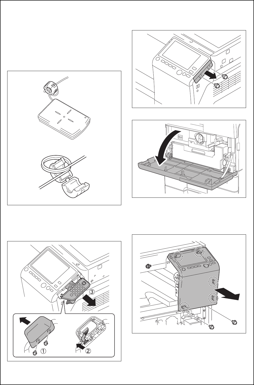
(2) Attach the ferrite core as shown in the illustra-
tion.
Note:
• Place the ferrite core such that the cable is
wound twice around the ferrite core.
• Place the ferrite core approximately 60 mm
away from the authentication unit.
(3)
<When the optional Keypad KP-101 is mounted>
Remove the two screws and remove the cover
on the back side of the keypad. Disconnect the
connector and remove the keypad.
<When the optional Keypad KP-101 is not
mounted>
Remove the cover from the main body as shown
in the illustration. (Two screws)
(4) Open the front door of the main body.
(5) Remove the three screws, release the six tabs,
and remove the control panel assembly.
Note:
Do not use too much force when removing as the
cable is connected.
E-3
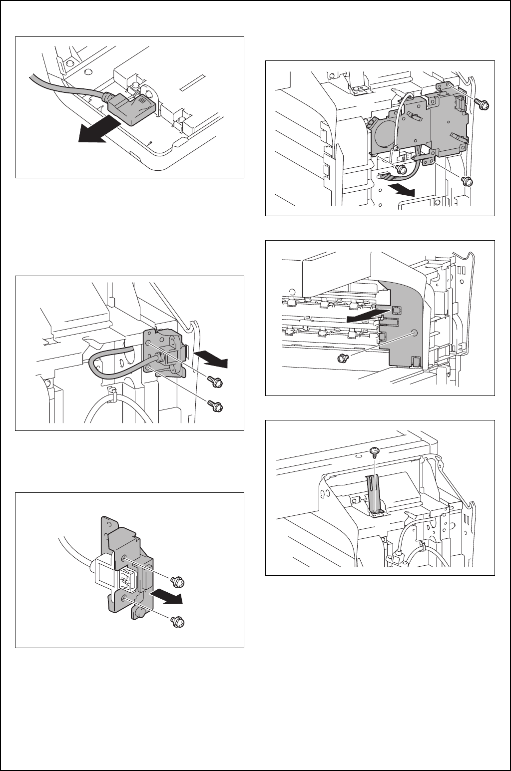
(6) Remove the cable from the control panel assem-
bly.
(7)
<When the Local Interface Kit EK-608 is not
mounted to the main body>
a) Remove the bracket shown in the illustration.
(Two screws)
Note:
Discard one of the two removed screws.
b) Remove the bracket from the USB cable.
(Two screws)
Note:
Discard the removed bracket and screws.
<When the Local Interface Kit EK-608 is mounted to
the main body>
Disconnect the connector and remove the local
interface board unit. (Three screws)
(8) Remove the control panel left cover. (One screw)
(9) Remove the plate spring. (One screw)
E-4
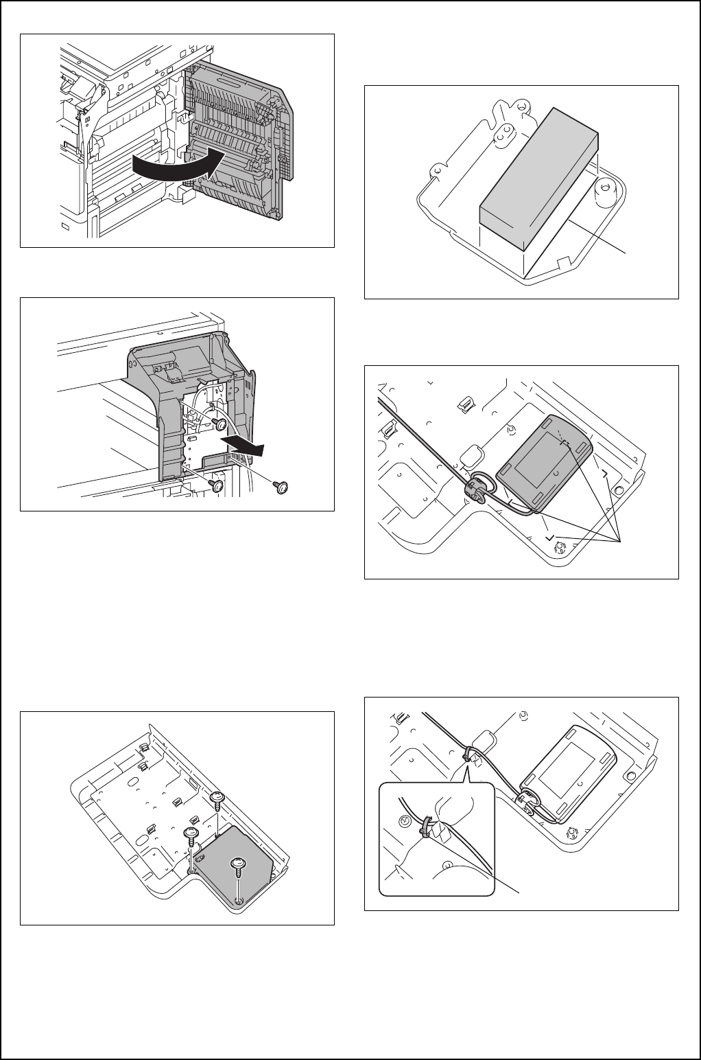
(10) Open the right door of the main body.
(11) Remove the control panel lower cover.
(Three screws)
(12)
<When the Working Table WT-506 is not mounted to
the main body>
Refer to the installation manual for the Working
Table WT-506 and install the working table.
(13) Remove the cover from the working table.
(Three screws)
Note:
The cushion, cable tie, and authentication label
are contained inside the cover.
(14)Paste the cushion to the cover, aligning the
cushion with the line marked inside the cover.
Note:
The cushion is supplied with the Working Table.
(15)Position the authentication unit, aligning its four
corners with the four marks indicated on the
underside of the working table.
(16) Secure the authentication unit cable to the
working table plate with the cable tie.
Note:
• The cable tie is supplied with the Working
Table.
• Cut the excess portion of the cable tie.
Line
Mark
A09NIXC020DA
Cable tie
E-5
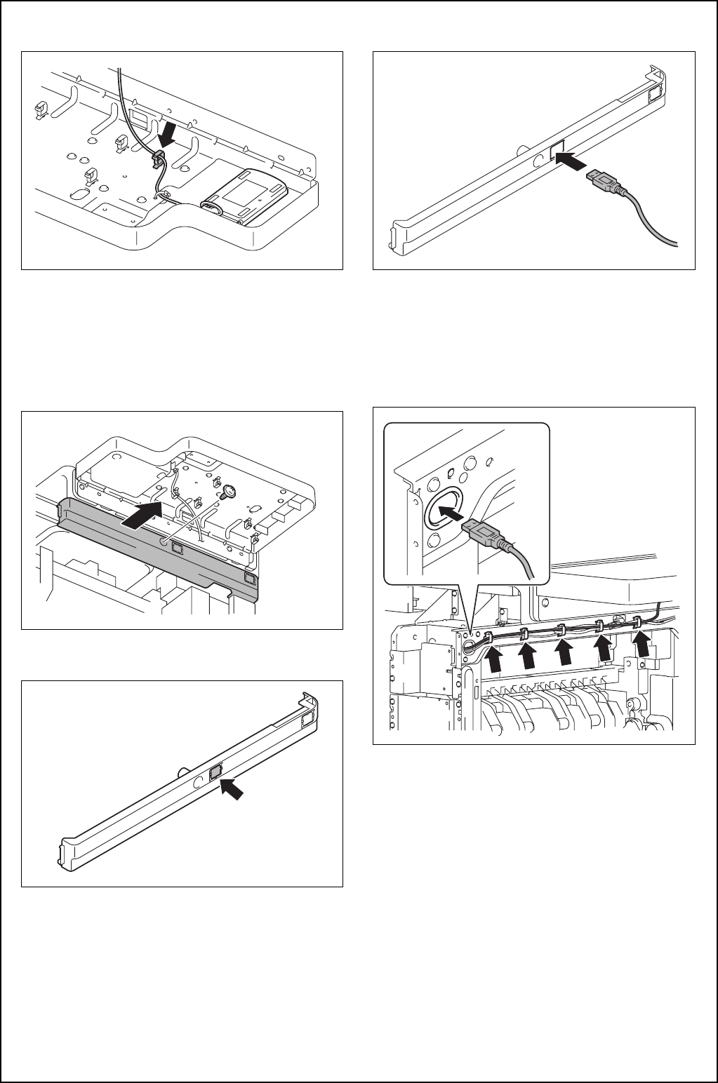
(17) Route the cable through the wire saddle shown
in the illustration.
(18) Attach the cover removed in step (13).
(Three screws)
Note:
Put the ferrite core inside the cover.
(19) Refer to the installation manual for the Working
Table WT-506 and install the working table.
(20) Remove the upper right cover. (One screw)
(21) Remove the indicated knockout from the upper
right cover.
(22) Route the authentication unit cable through the
notch in the upper right cover.
(23) Route the authentication unit cable through the
five wire saddles and pass it through the slot
shown in the illustration in the bracket on the
main body.
Note:
Make sure that there is no slack in cables at the
side of the working table.
(24) Reinstall the upper right cover. (One screw)
(25) To install the covers and others removed in
steps (8) to (11), reverse the removal proce-
dure.
E-6
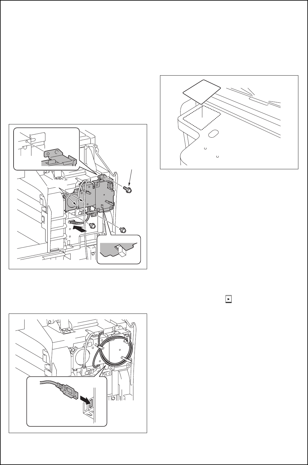
(26)
<When the bracket was removed in step (7)>
Refer to the installation manual for the Local
interface Kit EK-608 and install the local inter-
face kit to the main body.
<When the local interface board unit was removed in
step (7)>
Install the local interface board unit (three
screws) and connect the connector.
Note:
• The length of upper right screw A differs from
the other screws.
• Be careful not to pinch the harness.
• Route the cables through toward the front of the
unit.
(27) Connect the USB cable to the local interface
board unit and wind the excess cable around
the three wire saddles.
Note:
Connect to the port at the near side.
(28) To install the covers, connector, and others
removed in steps (3) to (6), reverse the removal
procedure.
(29) Paste the authentication label to the position
shown in the illustration.
Note:
The authentication label is supplied with the Work-
ing Table.
3. Installation of the loadable device driver
Install the AU-201S loadable driver (ICC_LDR.tar) to
the main body.
(1) Prepare a USB memory where only the loadable
device driver is stored in the ROOT directory.
(Please do not save any other data in the USB
memory.)
(2) Connect the USB memory to the USB port of the
main body.
(3) Plug the power cord into the power outlet and
turn ON the power switch.
(4) Display the Service Mode screen.
(For details of how to display the Service Mode
screen, see the service manual.)
(5) Touch “System 2” → → “Driver Install.”
(6) Touch “SET” and press Start key to install the
data.
(7) Check that the data are normally installed from
the message that appears on the control panel.
(8) Turn OFF the power switch.
(9) Remove the USB memory.
(10) Turn ON the power switch.
Note:
When displayed the Service Mode screen, be sure
to turn off the power after exiting the Service Mode
screen and wait for 10 seconds or more before
turning on.
Cable
A

E-7
4. Setting IC card authentication
(1) Display the Service Mode screen.
(For details of how to display the Service Mode
screen, see the service manual.)
(2) Display the Billing Setting screen.
(To display the Billing Setting screen, press Stop
→ 9 on the Control Panel.)
(3) Touch “Management Function Choice.”
(4) Touch “Authentication Device2.”
(5) Touch “Card.”
(6) Touch “END.”
(7) Turn OFF and ON the power switch.
Note:
When displayed the Service Mode screen, be sure
to turn off the power after exiting the Service Mode
screen and wait for 10 seconds or more before
turning on.