KONICA MINOLTA SKR3000P6 SKR 3000 User Manual Users manual
KONICA MINOLTA, Inc. SKR 3000 Users manual
UserManual.wiki
>
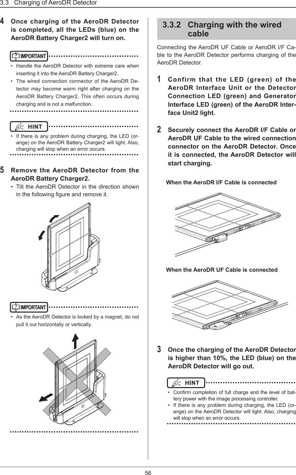
KONICA MINOLTA
>
SKR3000P6 User Manual
Users manual
Navigation menu
Upload a User Manual
Namespaces
Wiki Guide
HTML
PDF
Info
Views
User Manual
Discussion / Help
Navigation
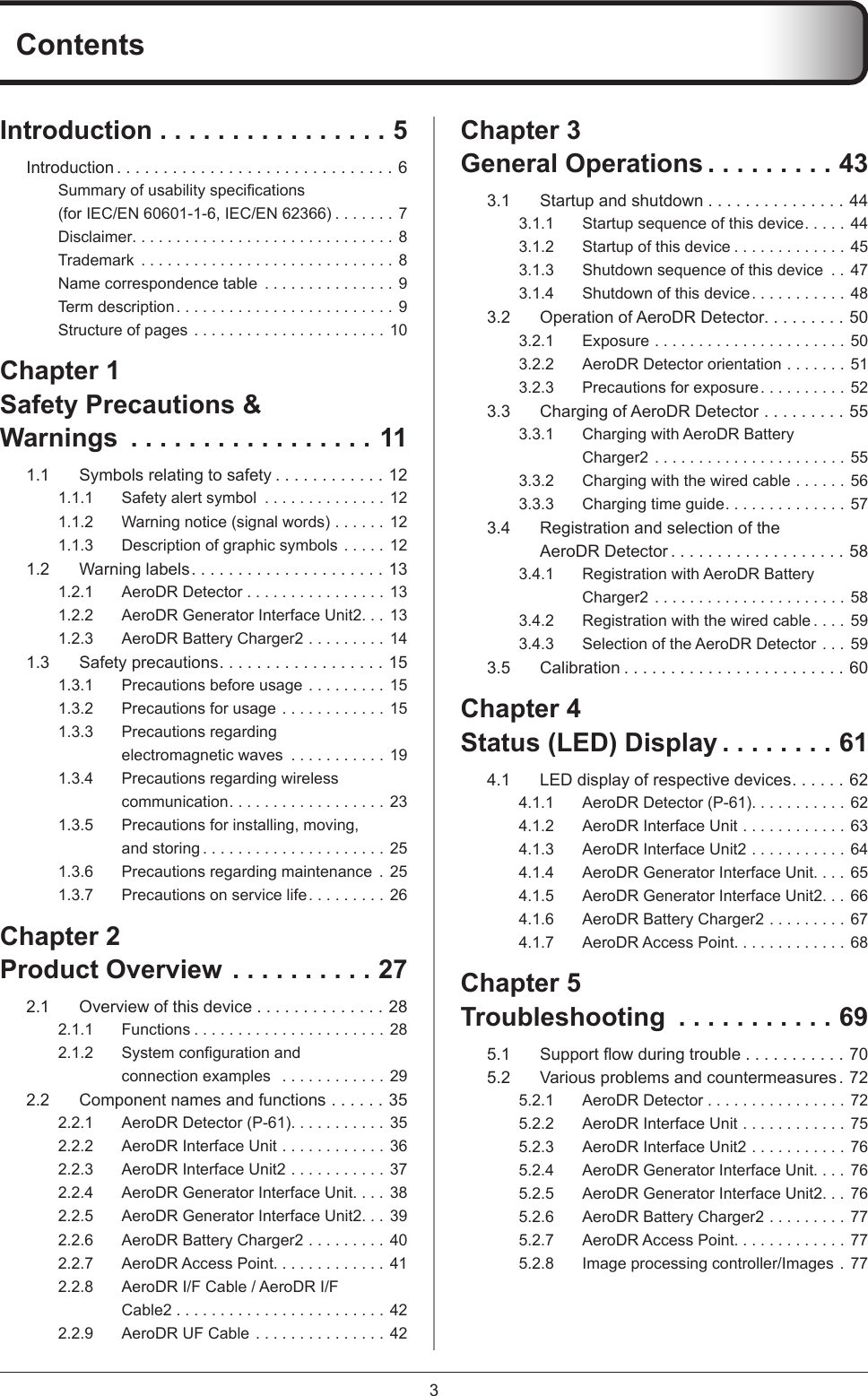

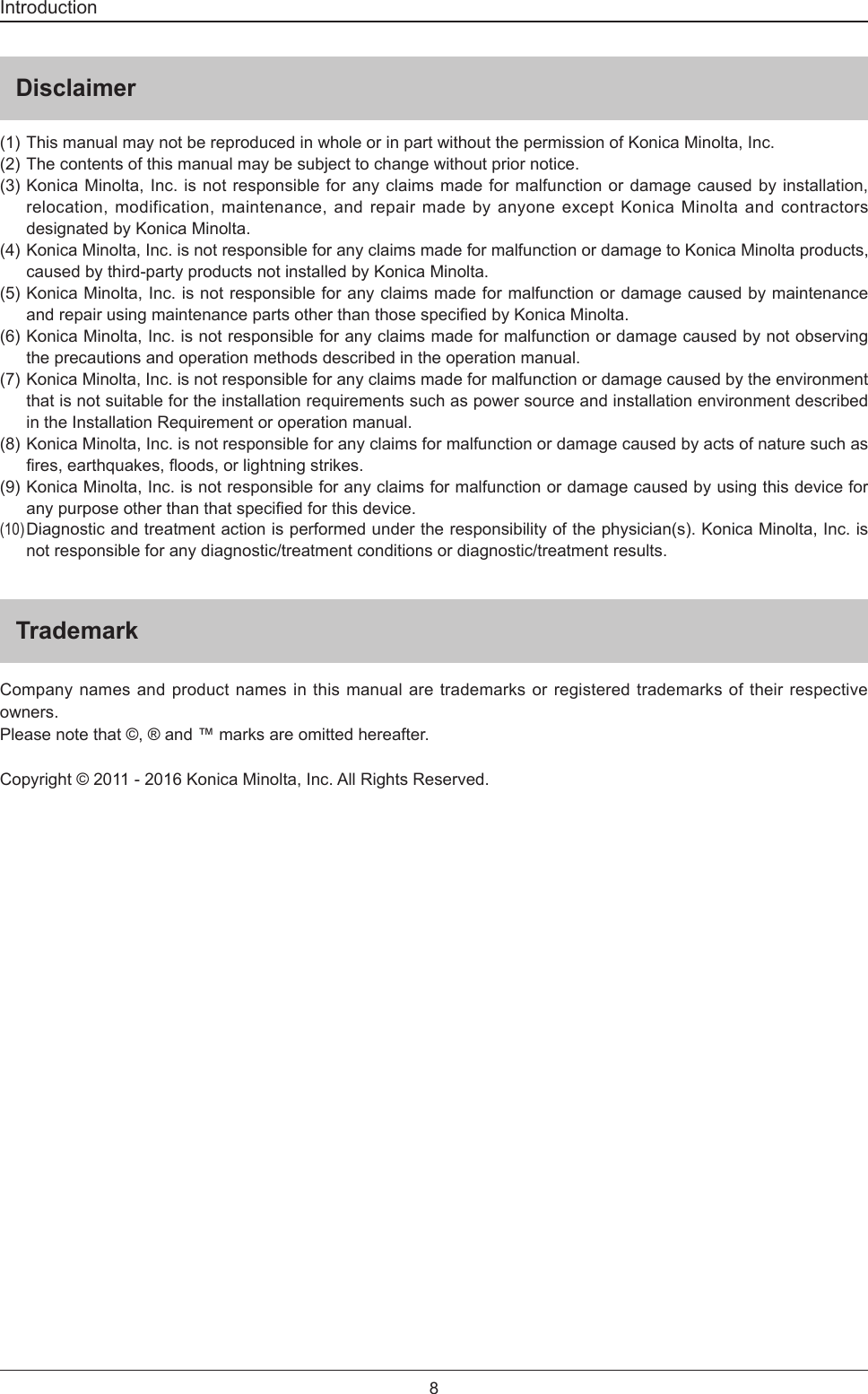
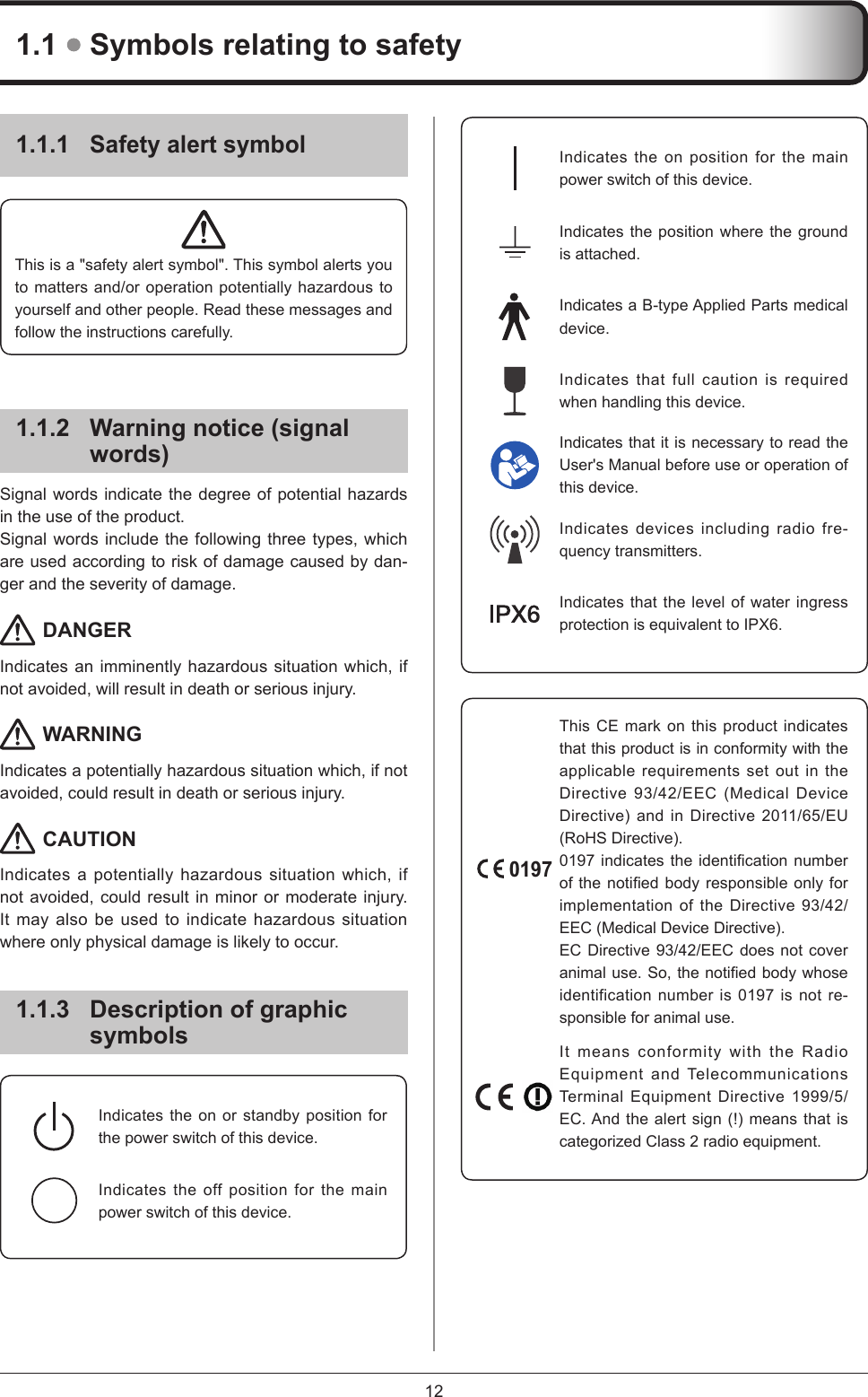
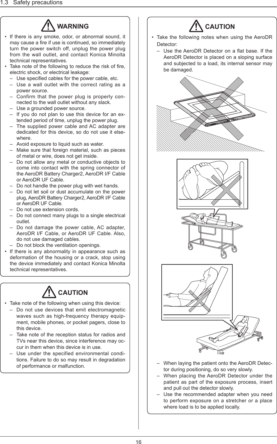
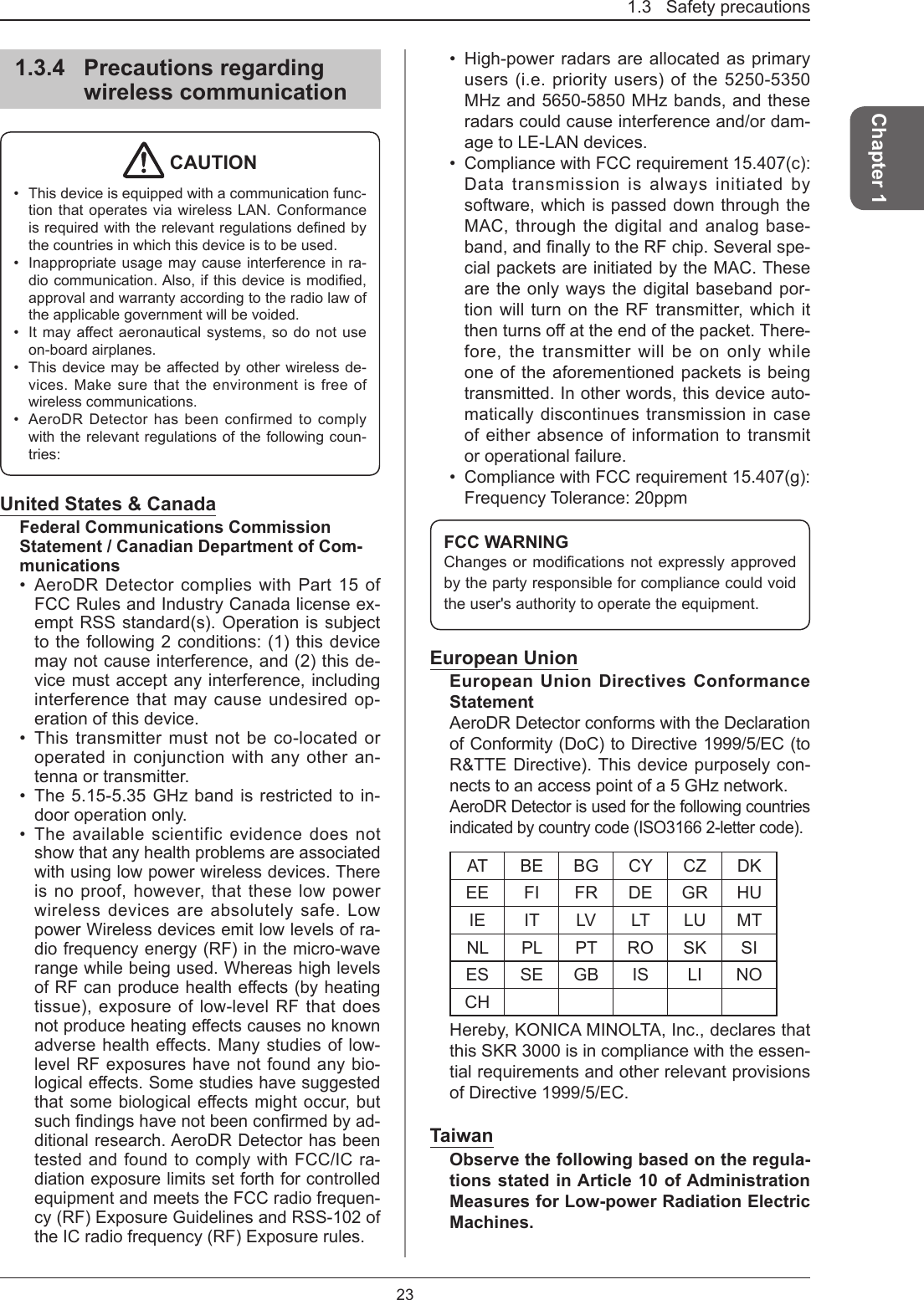
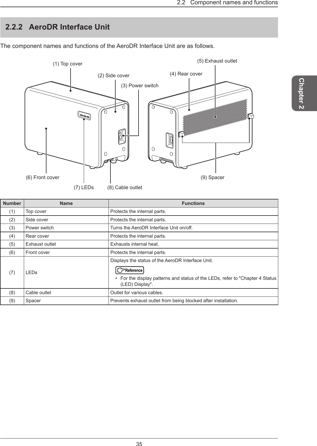
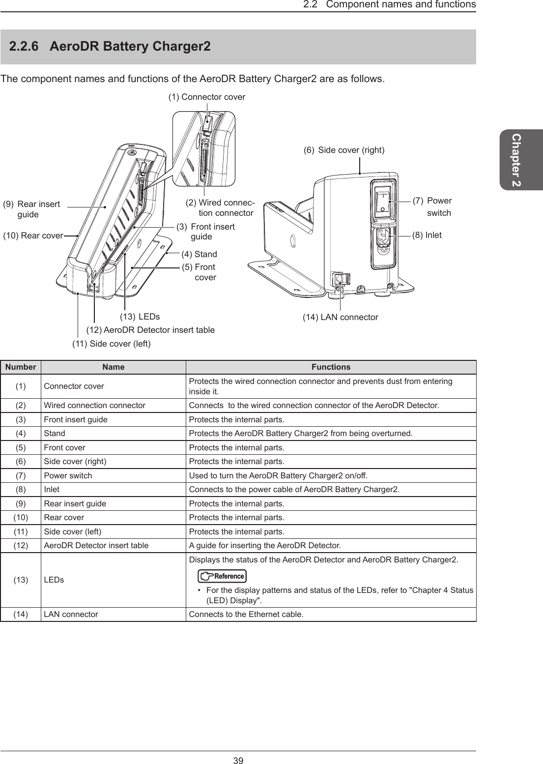
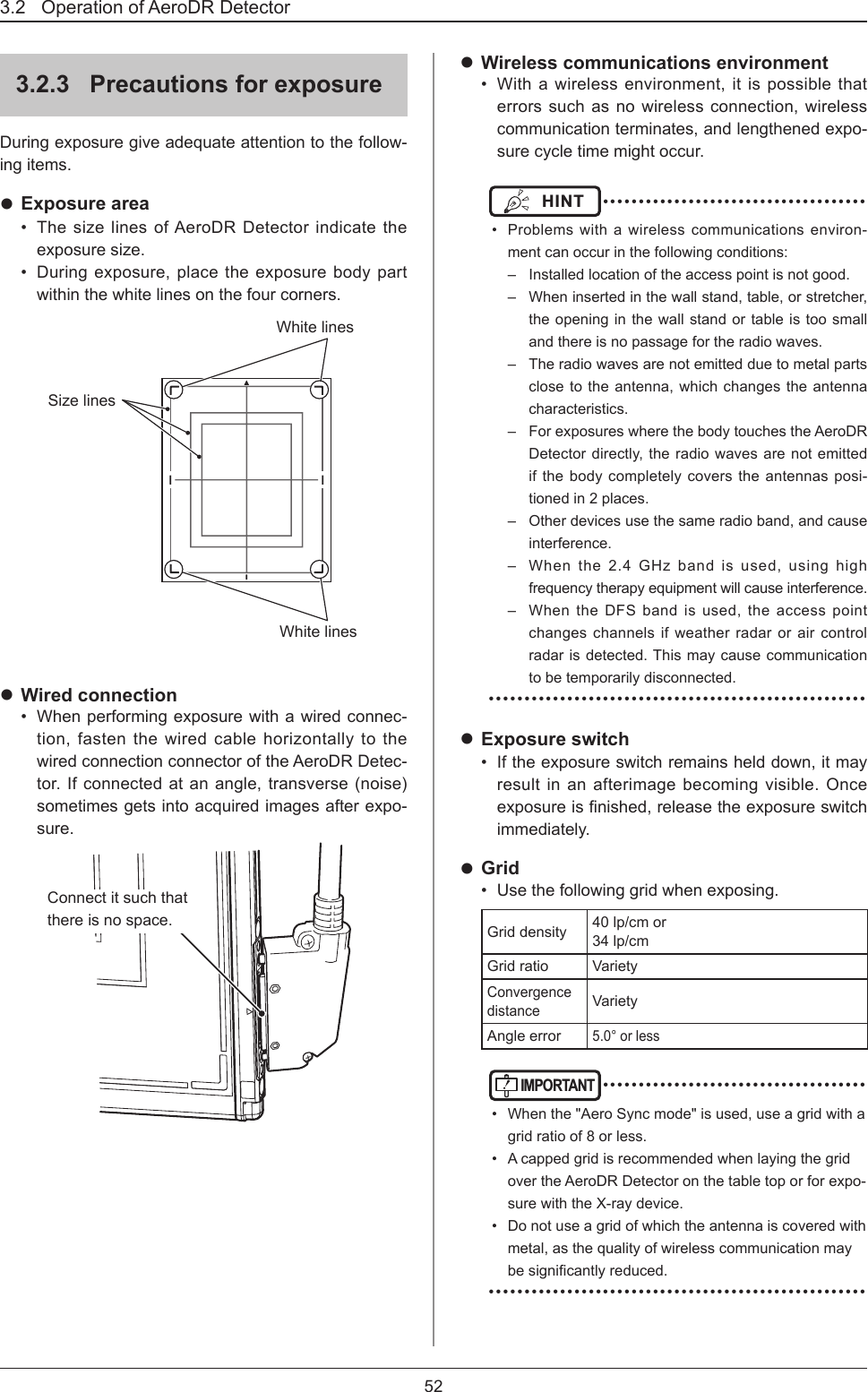
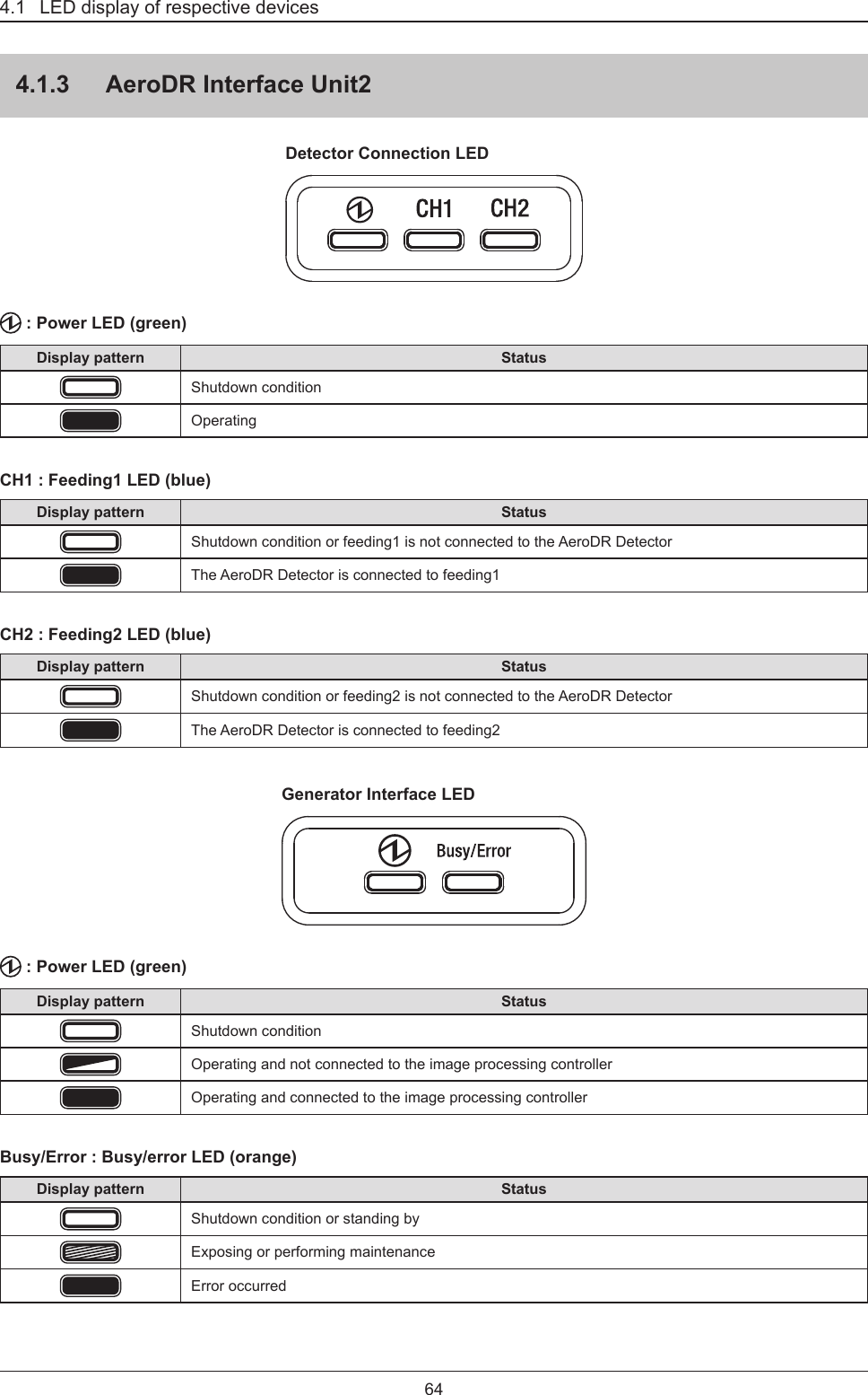
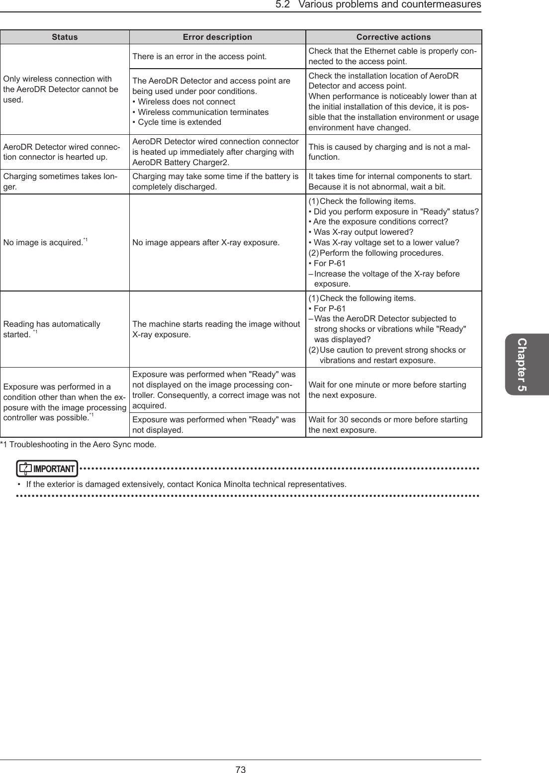
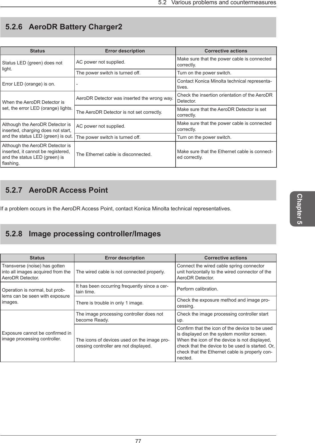
![201.3 Safety precautionsTable 1Guidelines and manufacture's declaration - electromagnetic emissionsThisdeviceisintendedforuseintheelectromagneticenvironmentspeciedbelow.The customer or the user of this device should assure that it is used in such an environment.Emissions test Compliance Electromagnetic environment - guidelinesRF emissionsCISPR 11 Group 1The device uses RF energy only for its internal function. Therefore, its RF emissions are very low and are not likely to cause any interference in nearby electronic equipment.RF emissionsCISPR 11 Class BThis device is suitable for use in all establishments including the following:Domestic establishments and those directly connected to the public low-voltage power supply network that supplies buildings for domestic purposes.Harmonic emissionsIEC 61000-3-2 Class AVoltageuctuations/ickeremissionsIEC 61000-3-3CompliesTable 2Guidelines and manufacturer's declaration - electromagnetic immunityThisdeviceisintendedforuseintheelectromagneticenvironmentspeciedbelow.The customer or the user of this device should assure that it is used in such an environment.Immunity test IEC 60601 test level Compliance level Electromagnetic environment - guidelinesElectrostatic discharge (ESD)IEC 61000-4-2± 6 kV contact ± 6 kV contact Floors should be wood, concrete or ceramictile.Ifoorsarecoveredwithsynthetic material, the relative humidity should be at least 30%. Mains power quality should be that of a typical com-mercial or hospital environment. ± 8 kV air ± 8 kV airElectrical fast transient/burstIEC 61000-4-4± 2 kV for power supply lines± 2 kV for power supply lines± 1 kV for input/output lines± 1 kV for input/output linesSurgeIEC 61000-4-5±1kVdierentialmode ±1kVdierentialmode Mains power quality should be that of a typical commercial or hospital environ-ment. ± 2 kV common mode ± 2 kV common modeVoltage dips, short interruptions and voltage variations on power supply input linesIEC 61000-4-11<5% UT (>95% dip in UT) for 0.5 cycle<5% UT (>95% dip in UT) for 0.5 cycle Mains power quality should be that of a typical commercial or hospital environ-ment. If the user of the device requires continued operation during power mains interruptions, it is recommended that the device be powered from an uninterrupted power supply or a battery.40% UT (60% dip in UT) for 5 cycles40% UT (60% dip in UT) for 5 cycles70% UT (30% dip in UT) for 25 cycles70% UT (30% dip in UT) for 25 cycles<5% UT (<95% dip in UT) for 5 sec<5% UT (<95% dip in UT) for 5 secPower frequency (50/60 Hz) magnetic eldIEC 61000-4-83 A/m 3 A/mPowerfrequencymagneticeldsshouldbe at levels characteristic of a typical lo-cation in a typical commercial or hospital environment.[NOTE] UT is the AC mains voltage prior to application of the test level.](https://usermanual.wiki/KONICA-MINOLTA/SKR3000P6/User-Guide-3202428-Page-20.png)
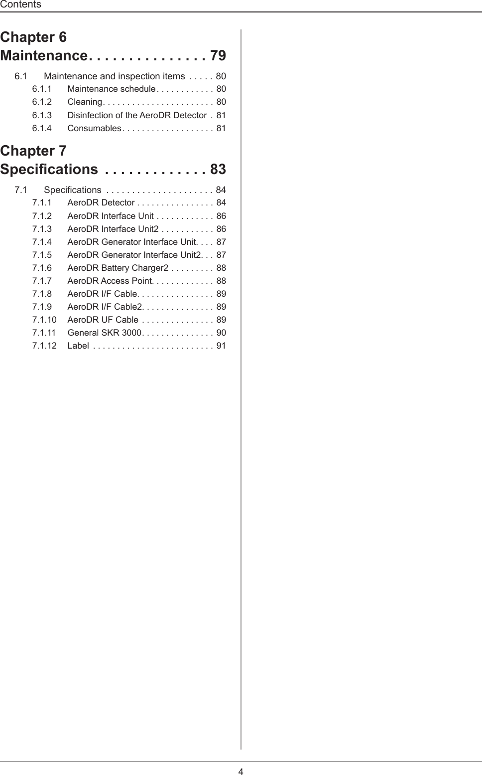
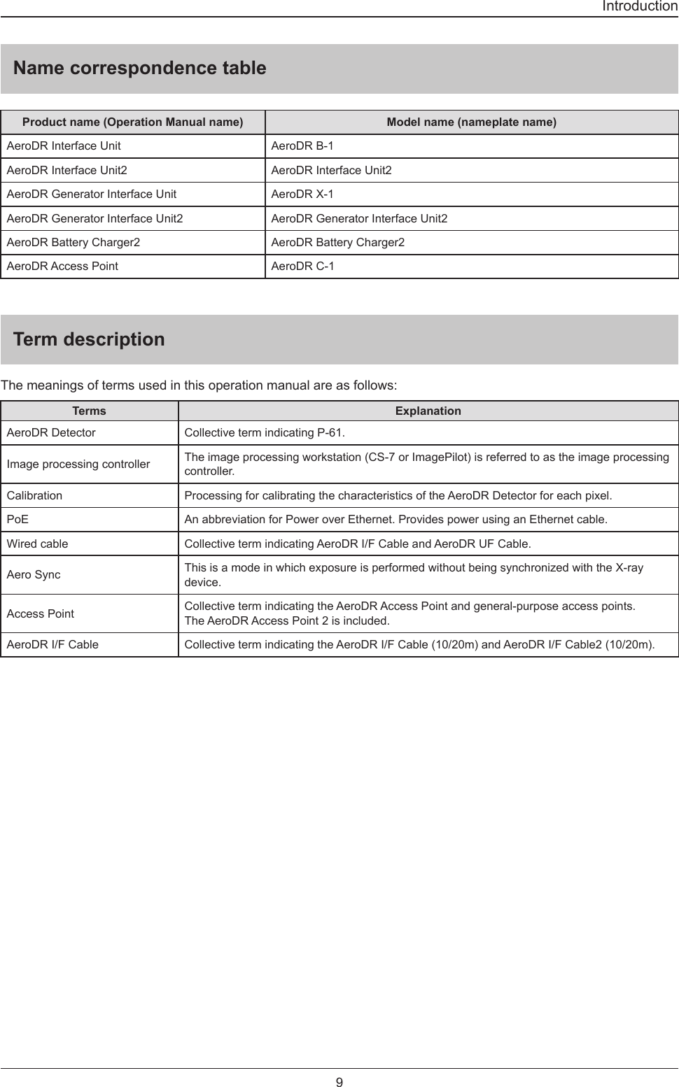
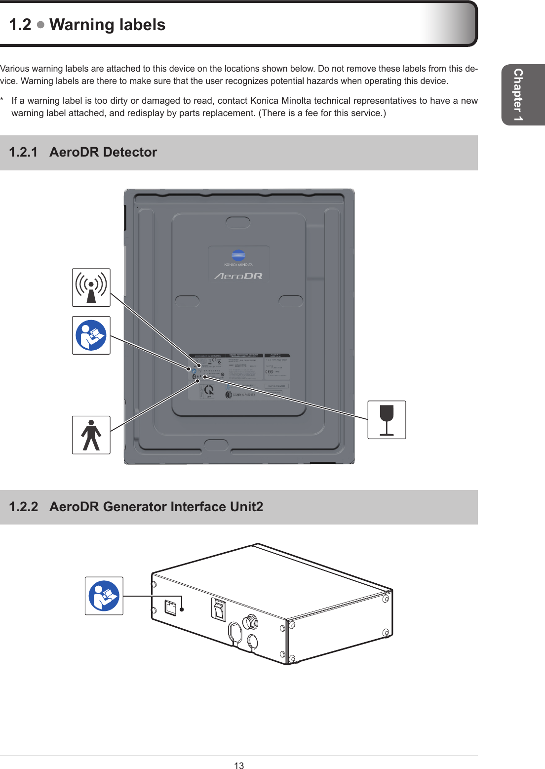
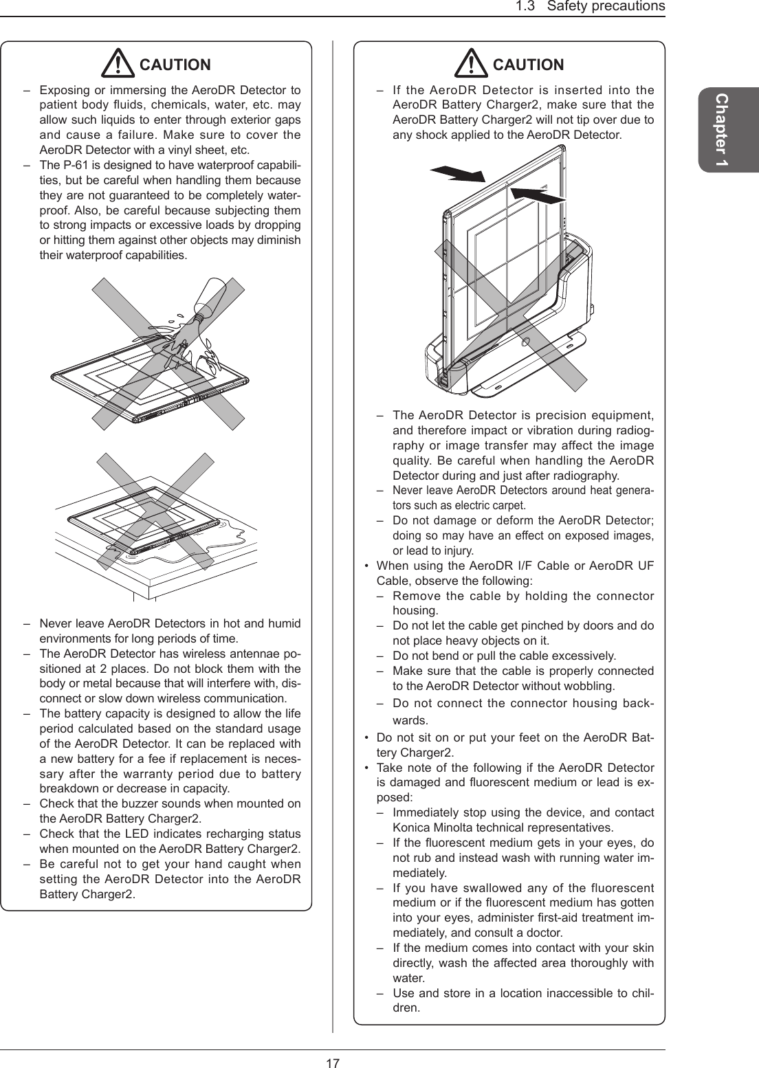
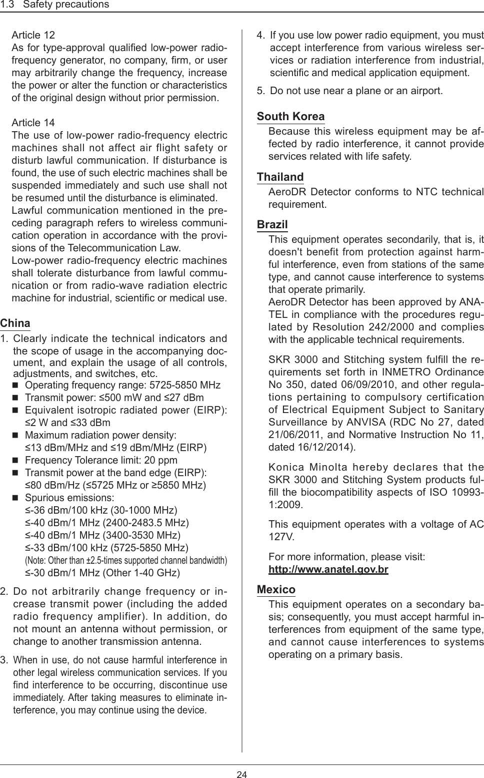
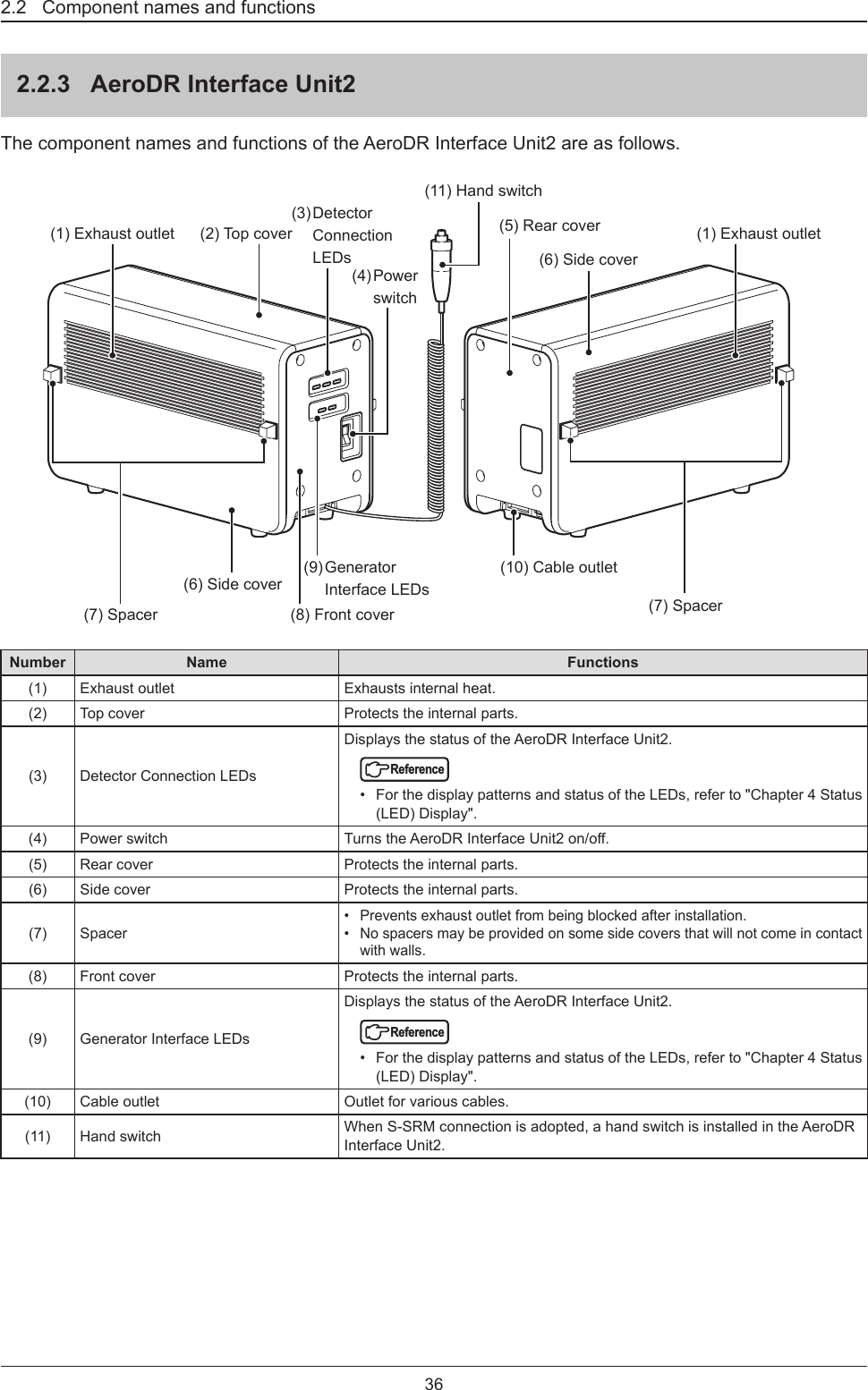
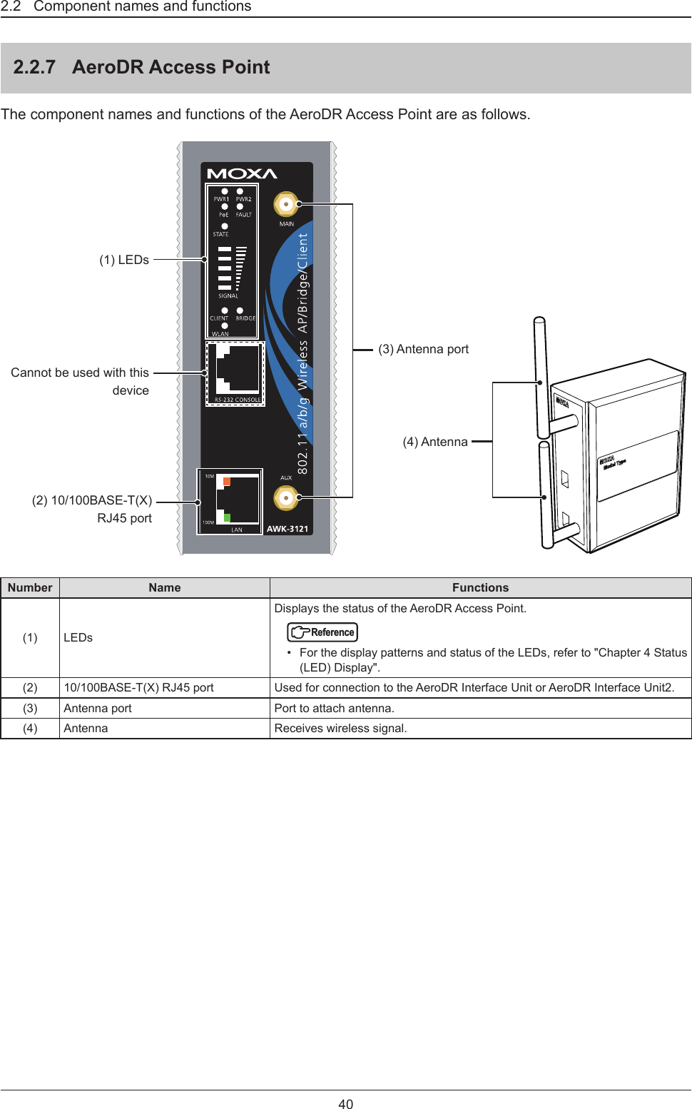
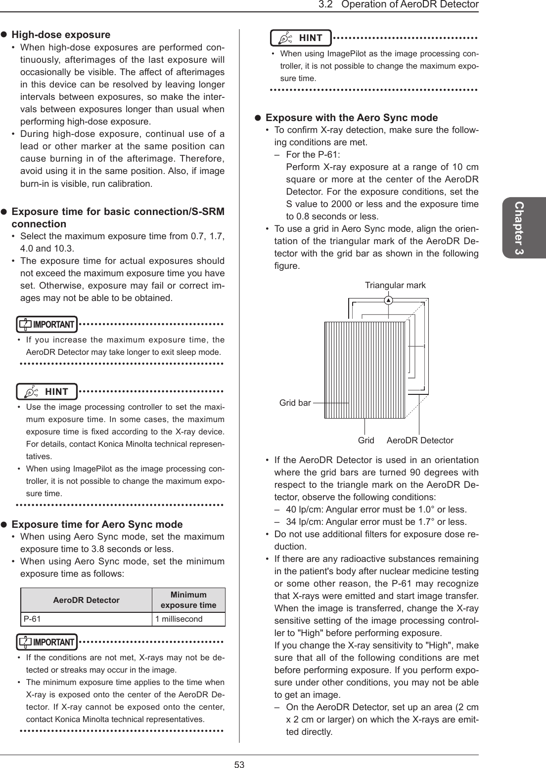
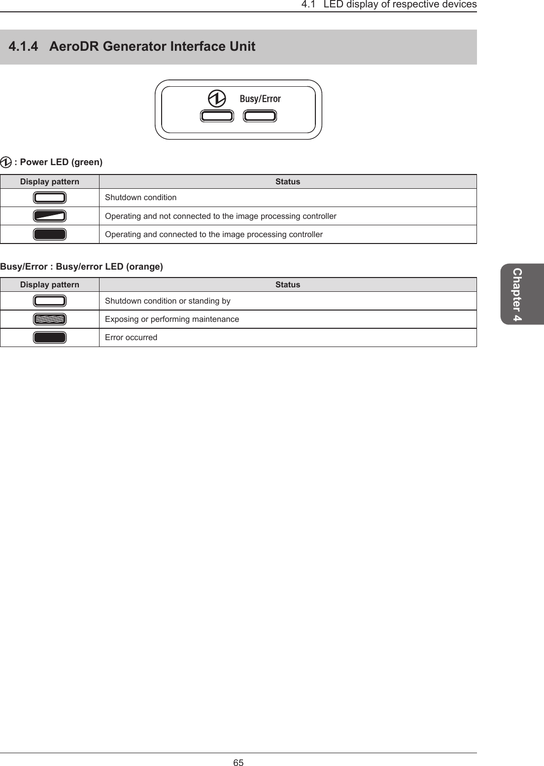
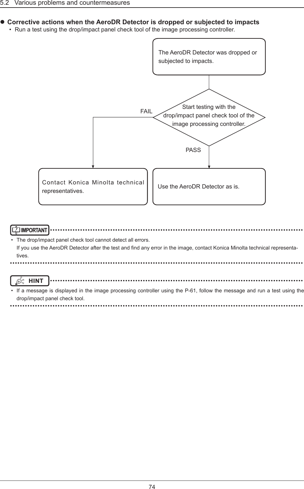
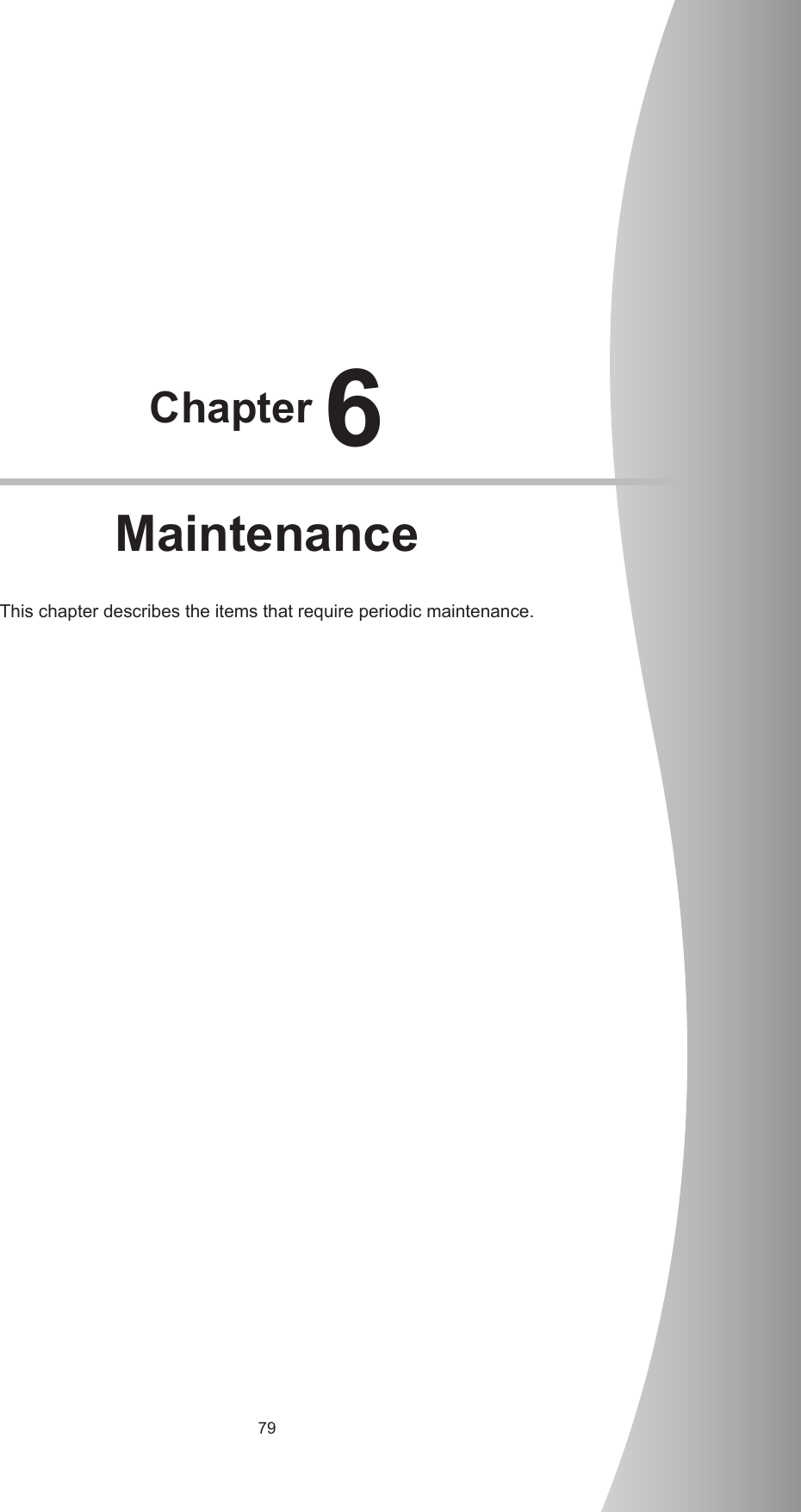
![21Chapter 11.3 Safety precautionsTable 3Guidelines and manufacturer's declaration - electromagnetic immunityThisdeviceisintendedforuseintheelectromagneticenvironmentspeciedbelow.The customer or the user of this device should assure that it is used in such an environment.Immunity test IEC 60601 test levelCompliance level Electromagnetic environment - guidelinesConducted RFIEC 61000-4-6Radiated RFIEC 61000-4-33 Vrms 150 kHzto 80 MHz3 V/m 80 MHzto 2.5 GHz[3] V[3] V/mPortable and mobile RF communications equipment should be used no closer to any part of this device, includ-ing cables, than the recommended separation distance calculated from the equation applicable to the frequency of the transmitter.Recommended separation distanced=[1.2] √Pd=[1.2] √P 80 MHz to 800 MHzd=[2.3] √P 800 MHz to 2.5 GHzwhere P is the maximum output power rating of the trans-mitter in watts (W) according to the transmitter manufac-turer and d is the recommended separation distance in meters (m).FieldstrengthsfromxedRFtransmitters,asdeterminedby an electromagnetic site surveya, should be less than the compliance level in each frequency rangeb.Interference may occur in the vicinity of equipment marked with the following symbol:[NOTE] At 80 MHz and 800 MHz, the separation distance for the higher frequency range applies. [NOTE] Theseguidelinesmaynotapplyinallsituations.Electromagneticpropagationisaectedbyabsorptionandreectionfromstructures,objectsandpeople.a Fieldstrengthsfromxedtransmitters,suchasbasestationsforradio(cellular/cordless)telephonesandlandmobileradios, amateur radio, AM and FM radio broadcast and TV broadcast cannot be predicted theoretically with accuracy. ToassesstheelectromagneticenvironmentduetoxedRFtransmitters,anelectromagneticsitesurveyshouldbeconsidered.IfthemeasuredeldstrengthinthelocationinwhichthisdeviceisusedexceedstheapplicableRFcom-pliance level above, this device should be observed to verify normal operation. If abnormal performance is observed, additional measures may be necessary, such as reorienting or relocating this device.b Overthefrequencyrange150kHzto80MHz,eldstrengthshouldbelessthan[3]V/m.](https://usermanual.wiki/KONICA-MINOLTA/SKR3000P6/User-Guide-3202428-Page-21.png)
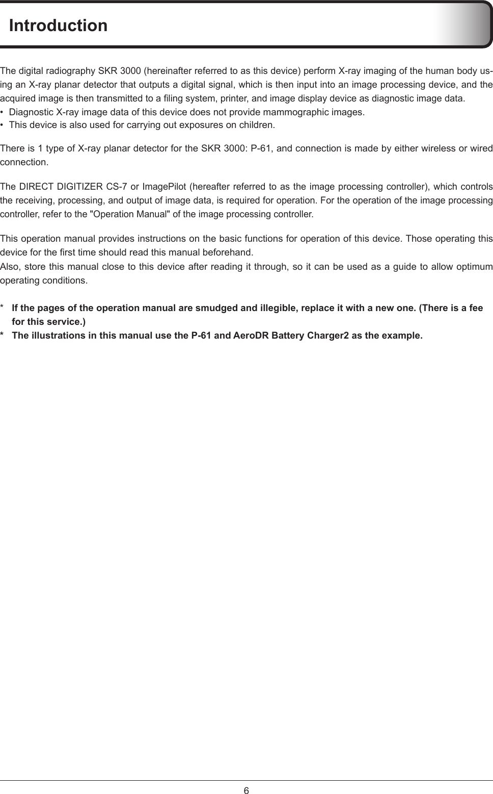
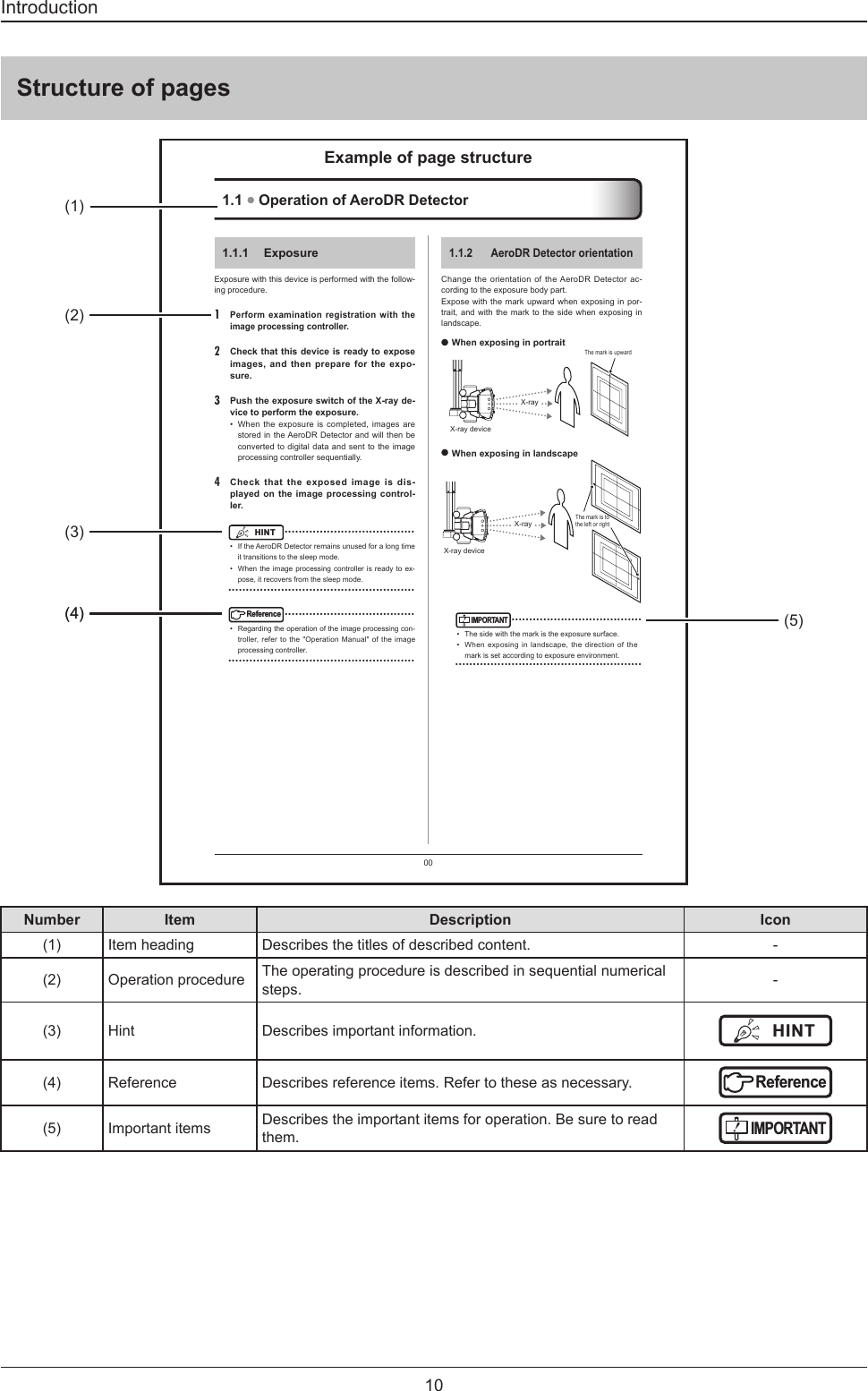
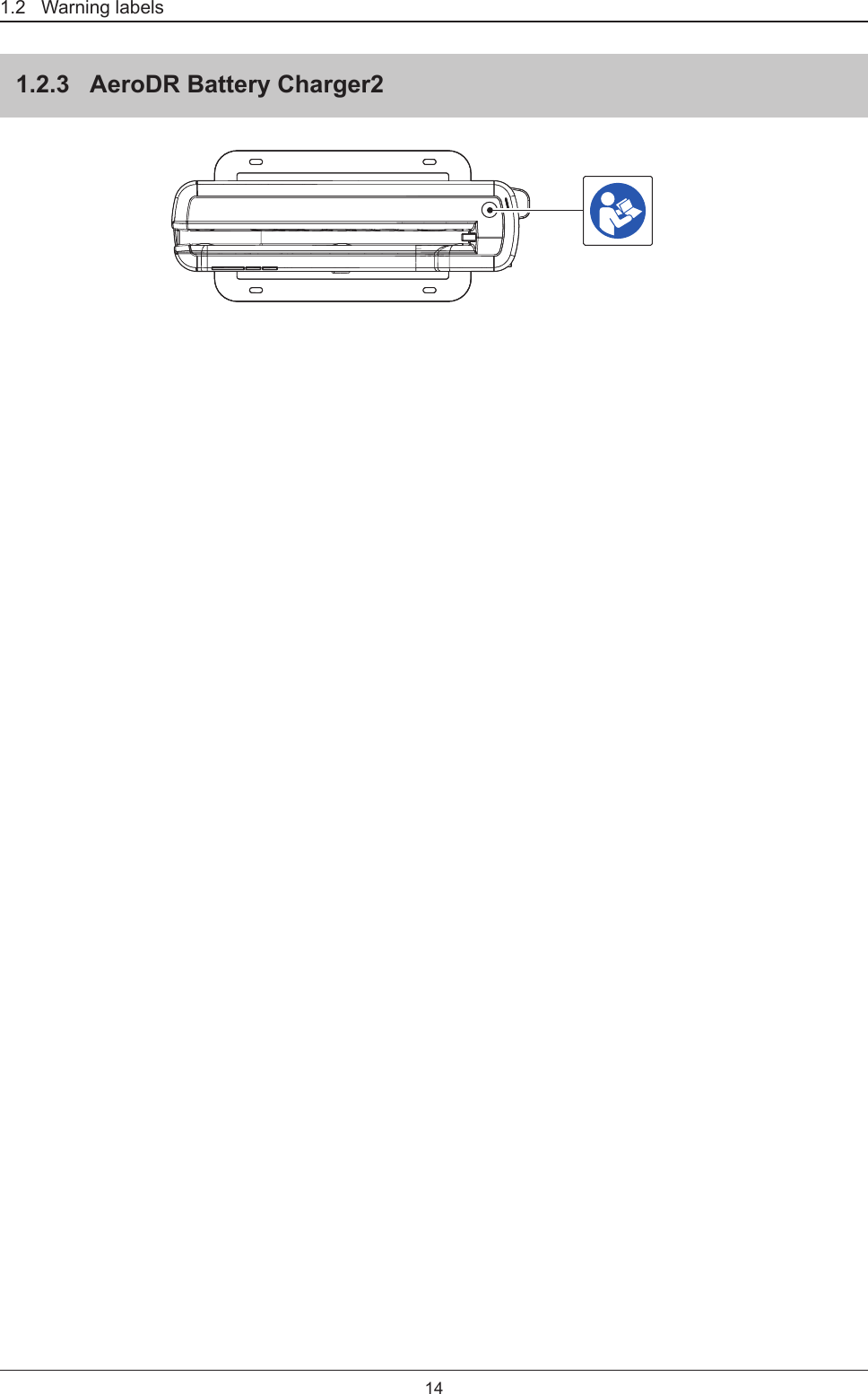
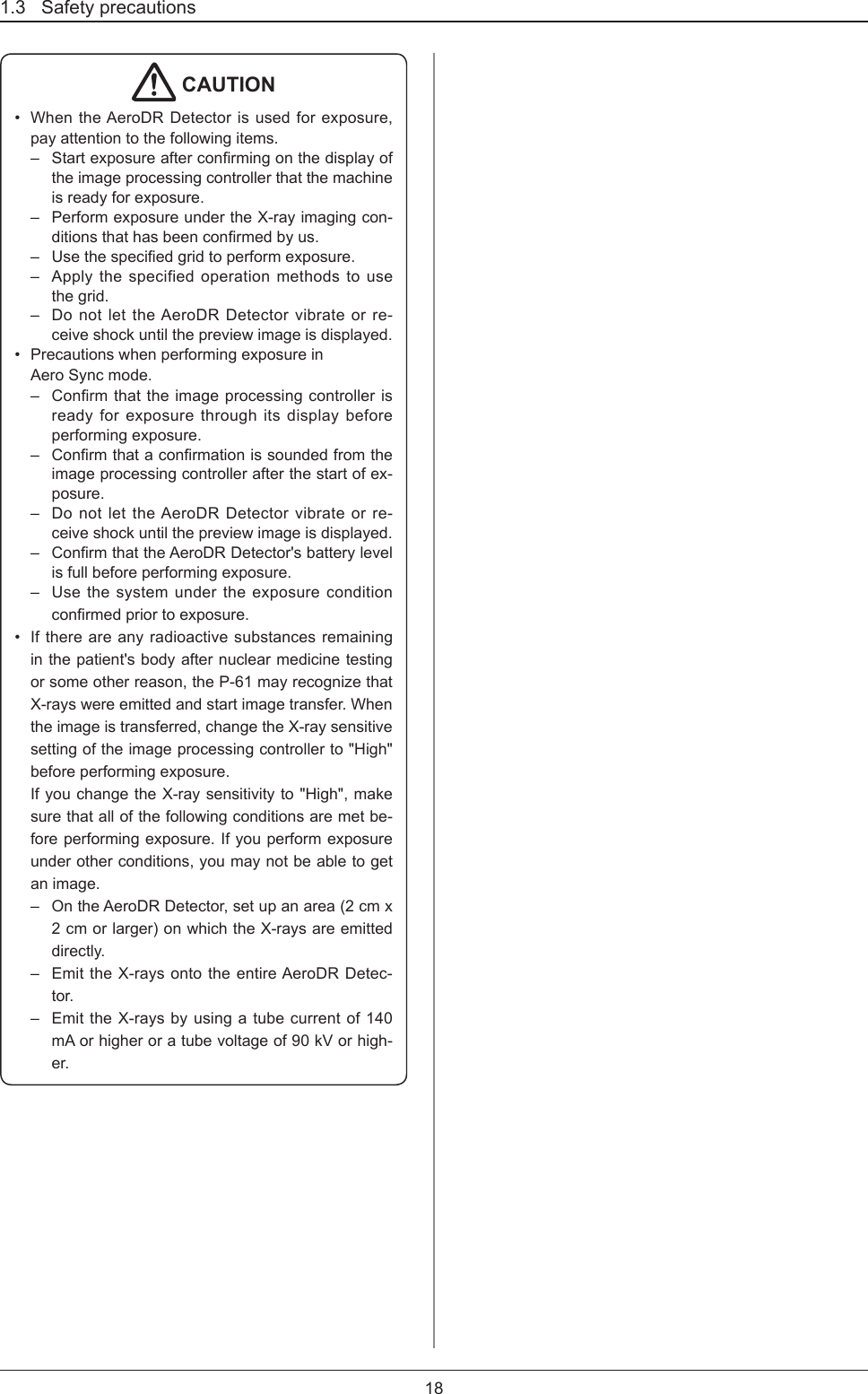
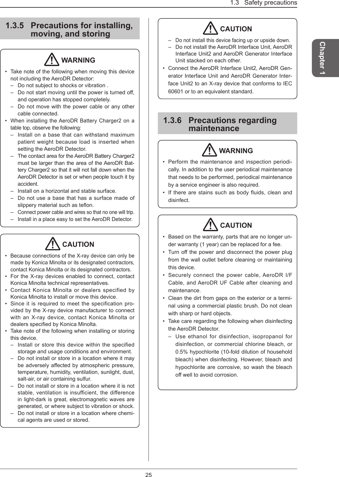
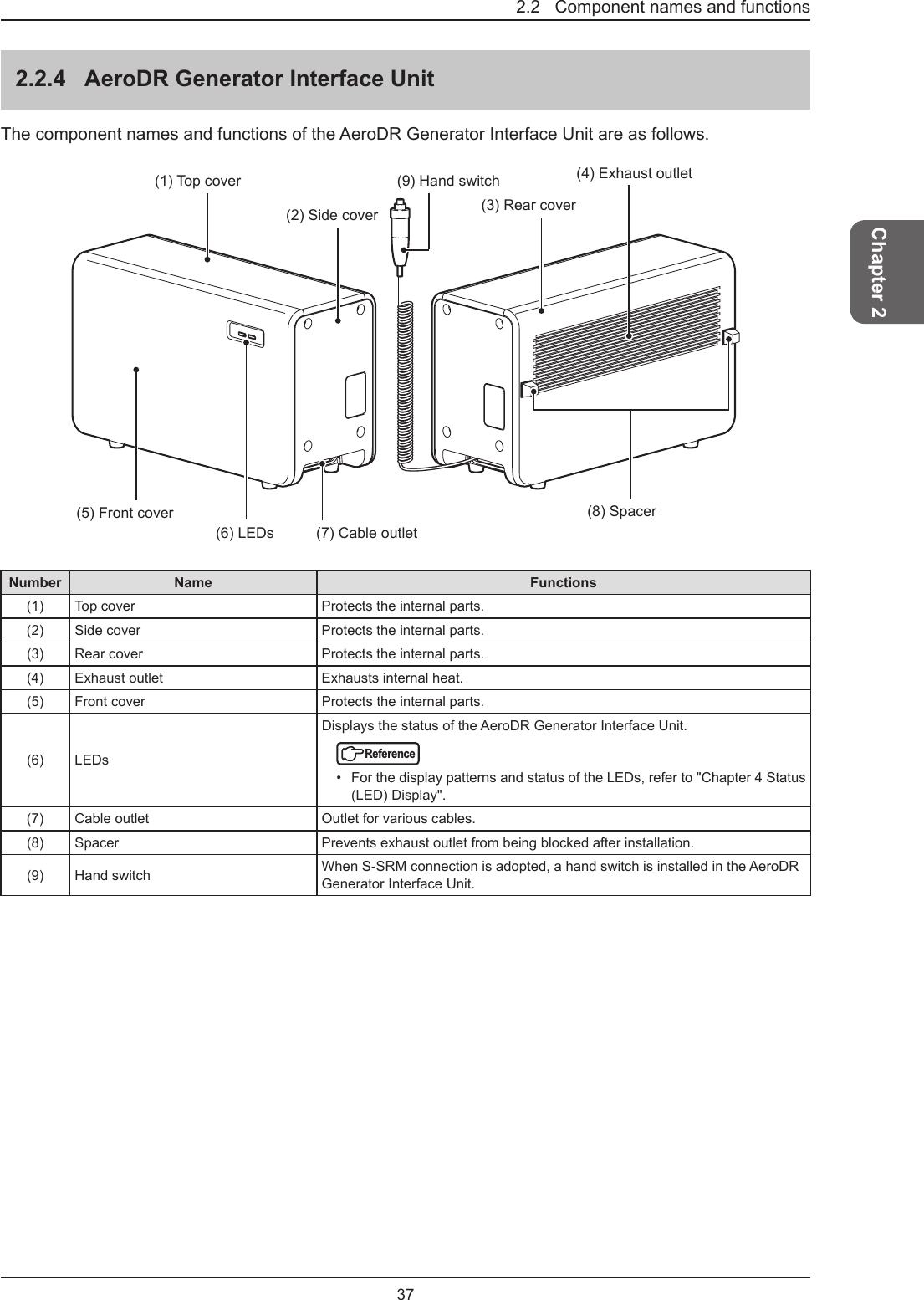
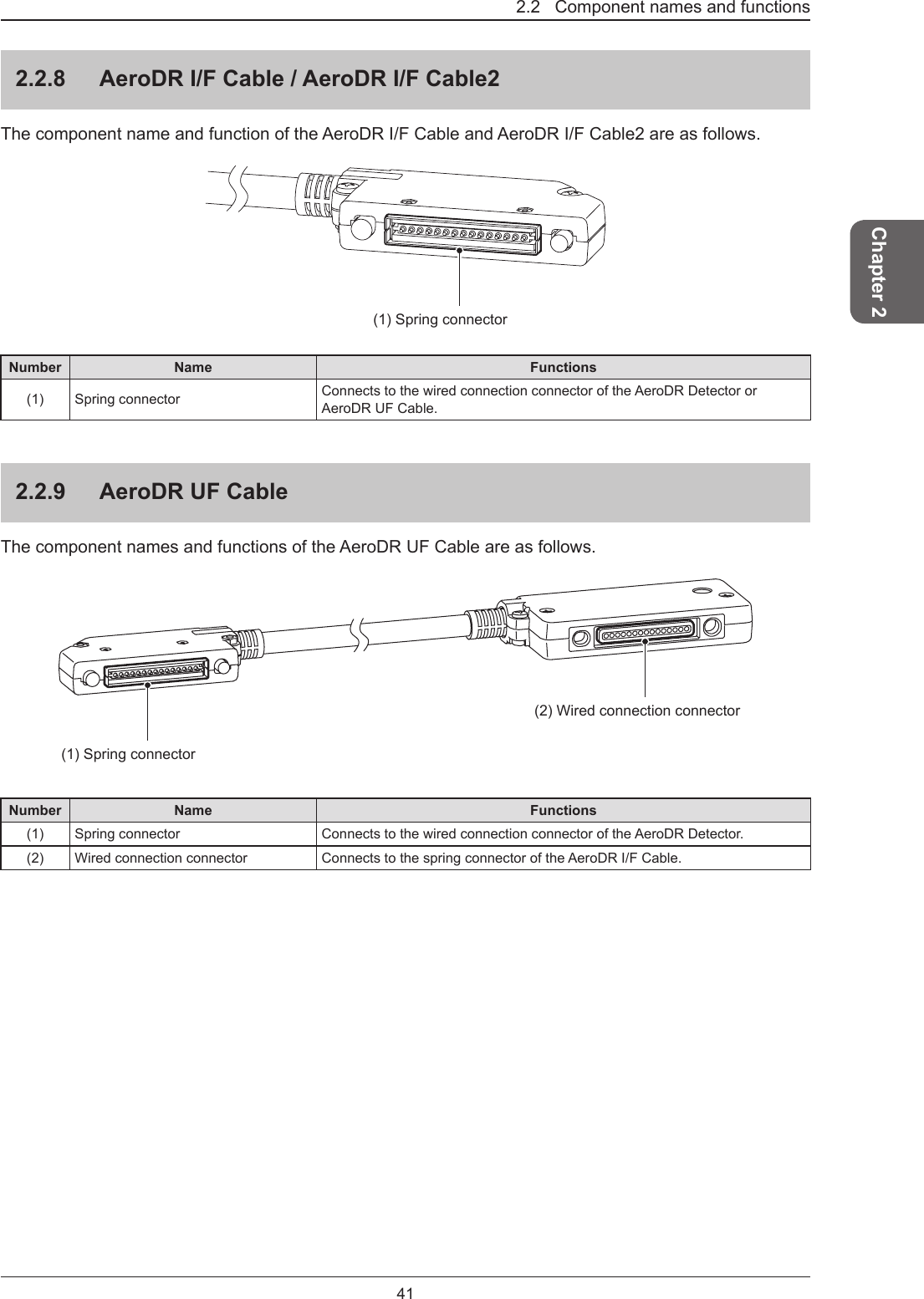
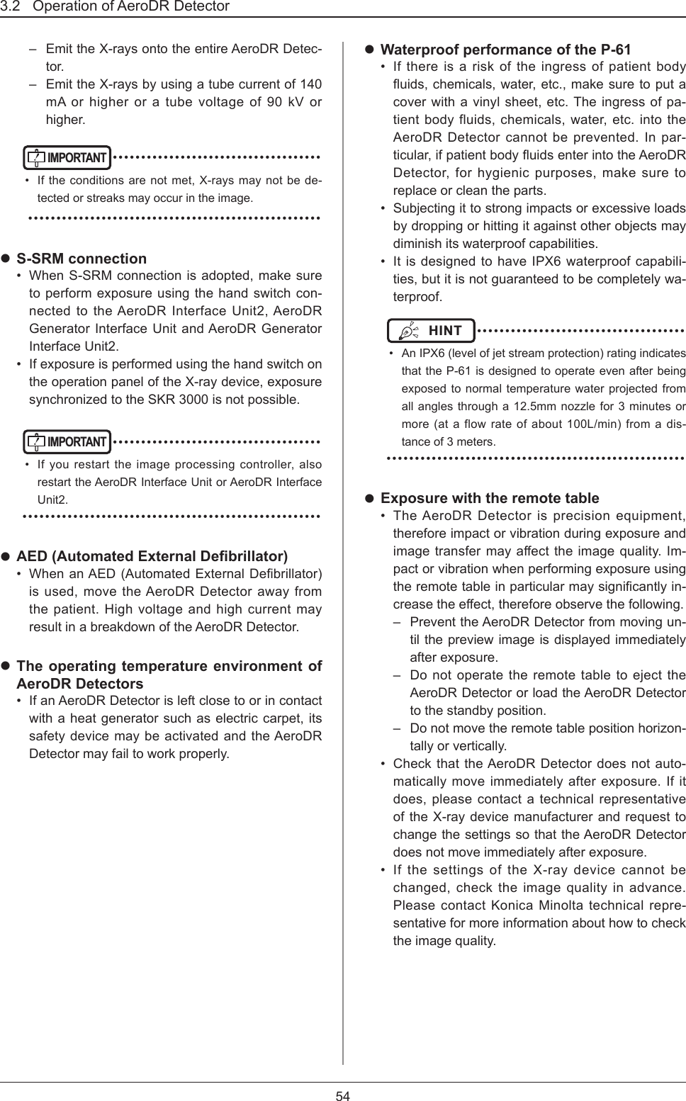
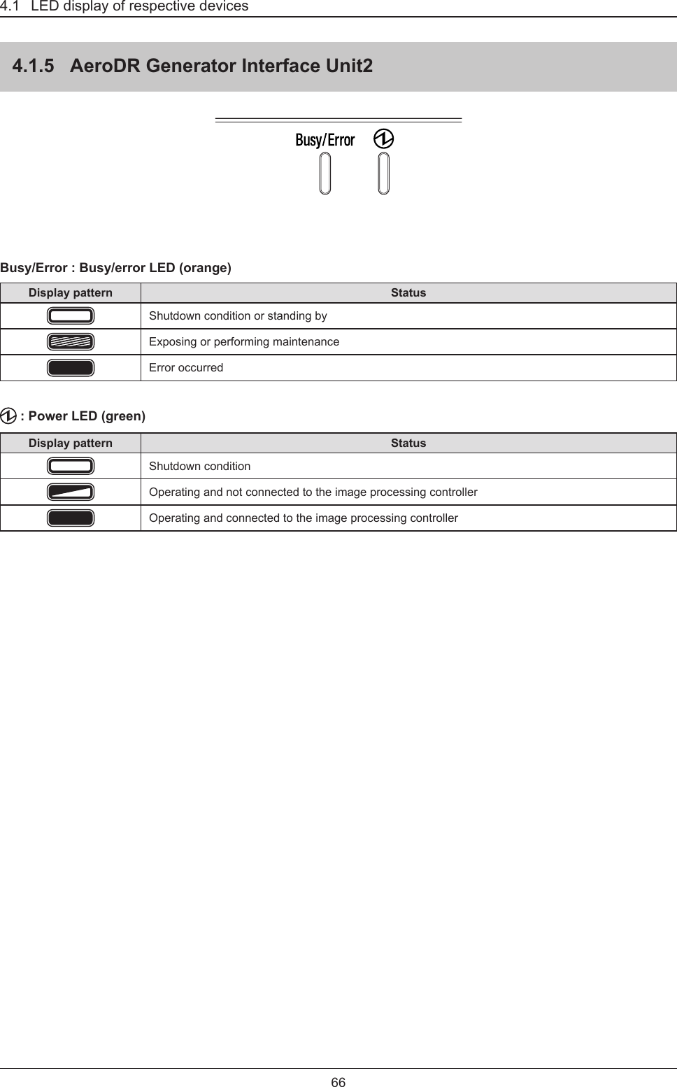
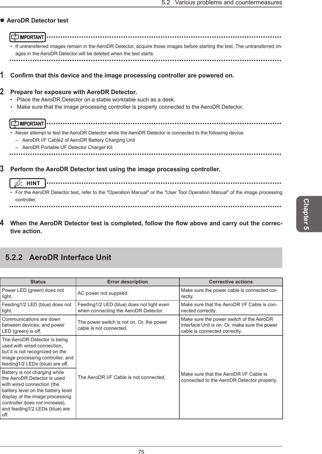
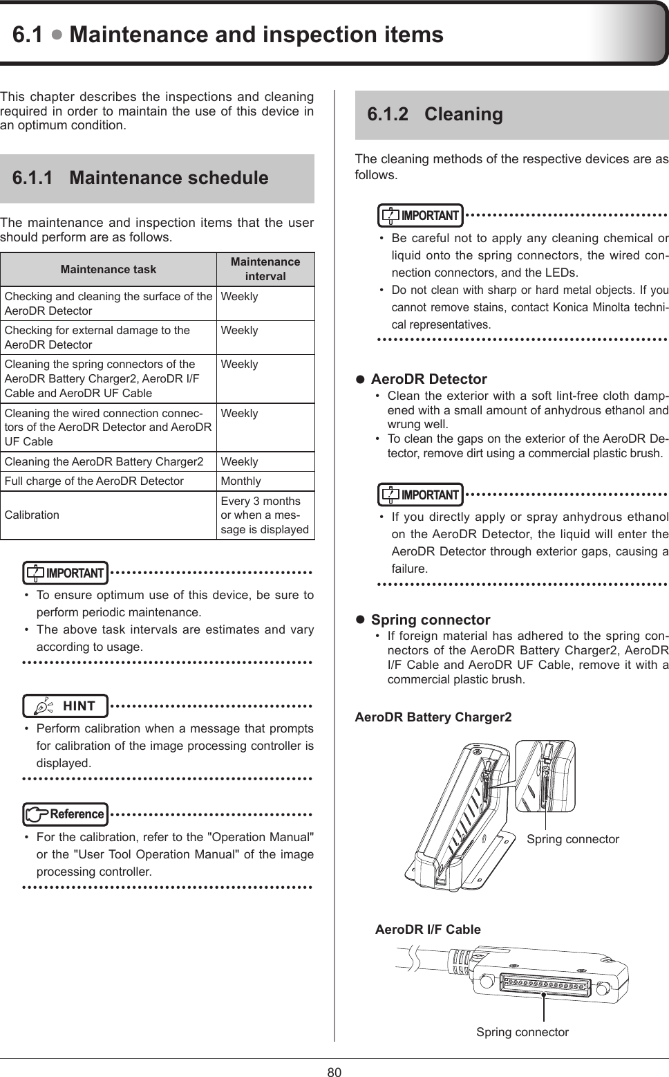
![221.3 Safety precautionsTable 4Recommended separation distance between portable and mobile RF communications equipment and the deviceThis device is intended for use in an electromagnetic environment in which radiated RF disturbances are controlled. The customer or the user of this device can help prevent electromagnetic interference by maintaining a minimum distance between portable and mobile RF communications equipment (transmitters) and this device as recommended below, according to the maximum output power of the communications equipment.Rated maximum output power of the transmitterWSeparation distance according to frequency of transmitterm150 kHz to 80 MHzd=[1.2] √P80 MHz to 800 MHzd=[1.2] √P800 MHz to 2.5 GHzd=[2.3] √P0.01 0.12 0.12 0.230.1 0.38 0.38 0.731 1.2 1.2 2.310 3.8 3.8 8100 12 12 23For transmitters rated at a maximum output power not listed above, the recommended separation distance d in meters (m) can be estimated using the equation applicable to the frequency of the transmitter, where P is the maximum output power rating of the transmitter in watts (W) according to the transmitter manufacturer.[NOTE] At 80 MHz and 800 MHz, the separation distance for the higher frequency range applies. [NOTE] These guidelines may not apply in all situations. Electromagnetic propagation is affected by absorption and reectionfromstructures,objectsandpeople.](https://usermanual.wiki/KONICA-MINOLTA/SKR3000P6/User-Guide-3202428-Page-22.png)
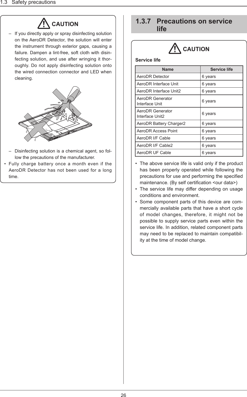
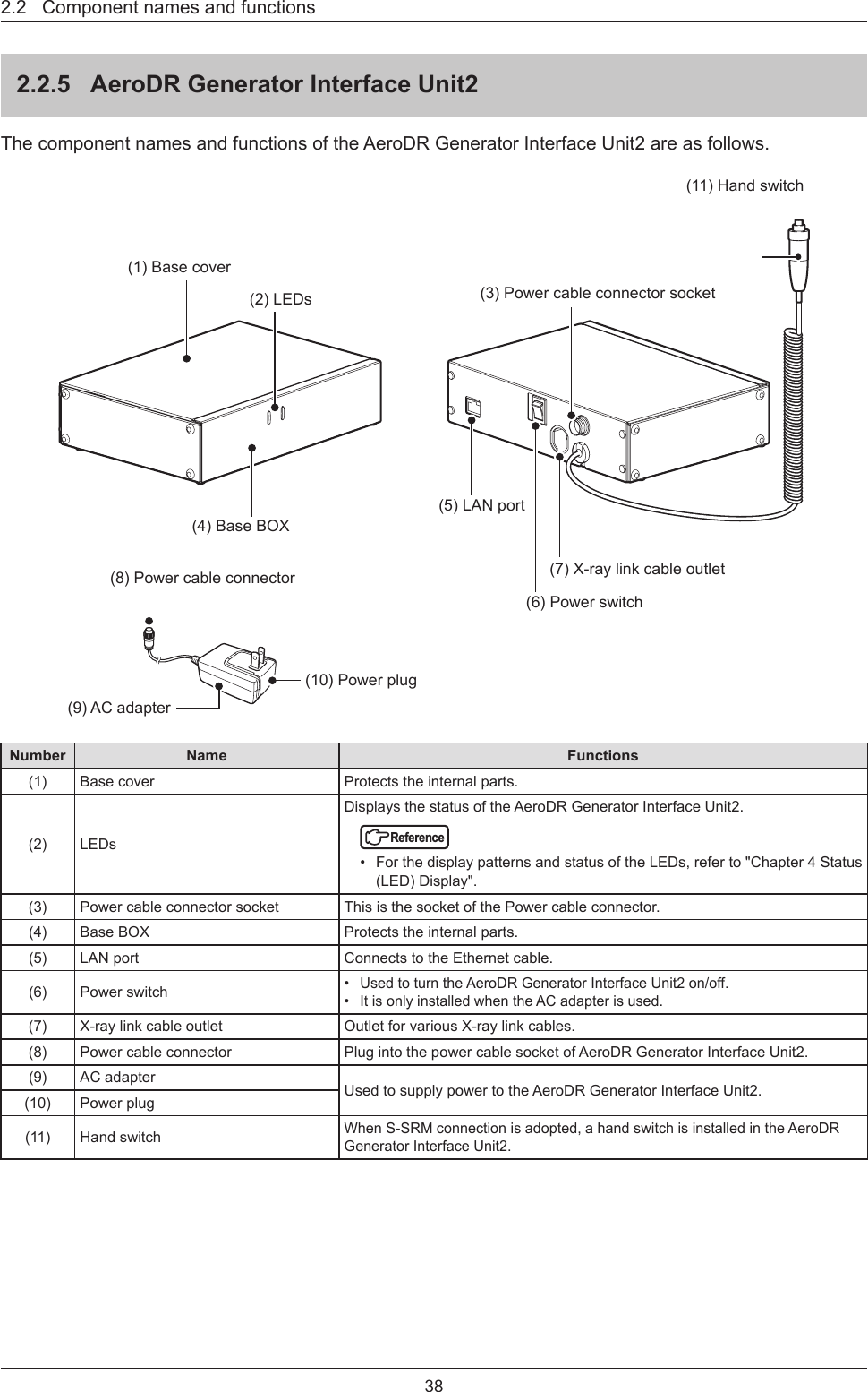

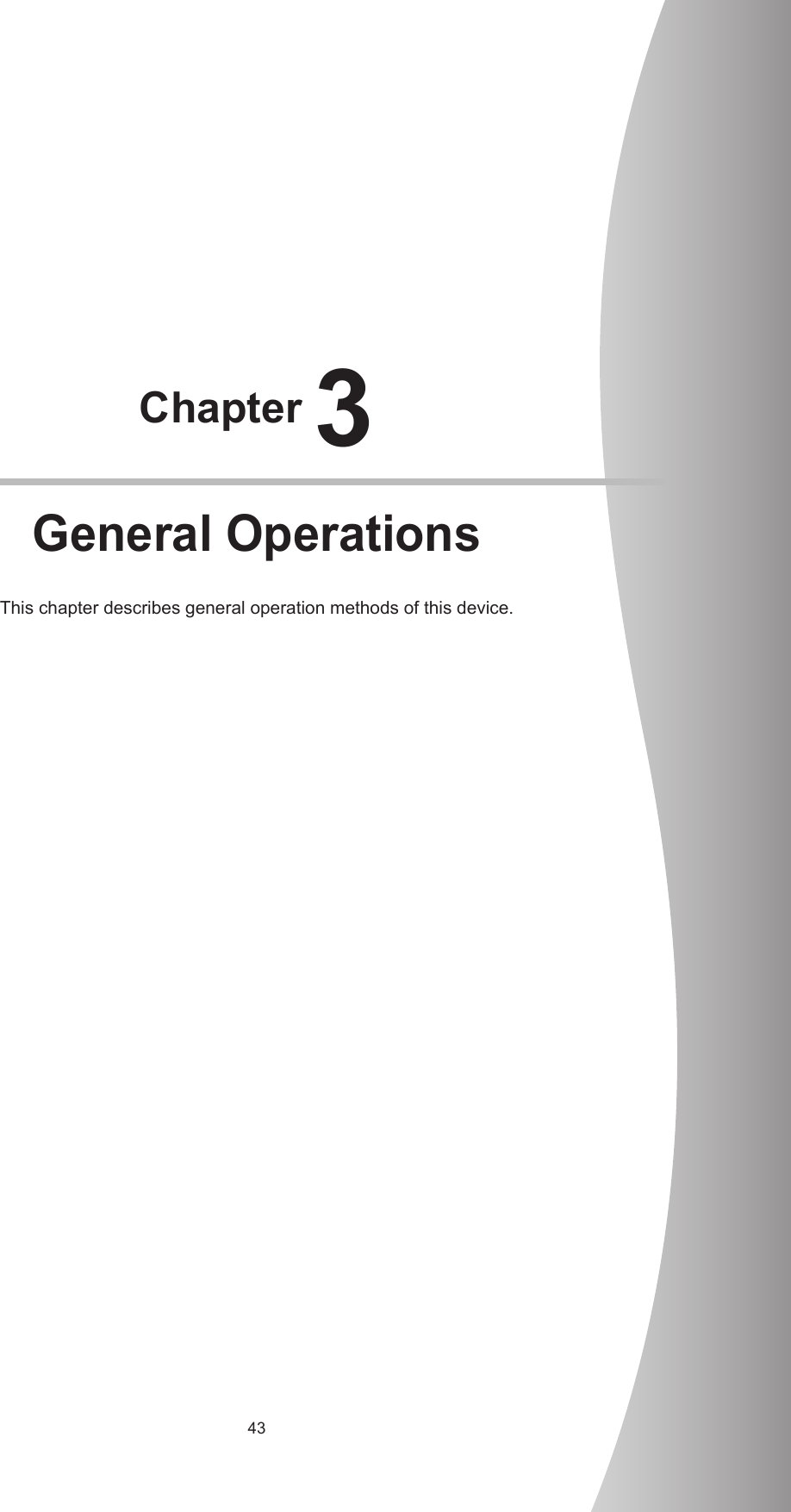
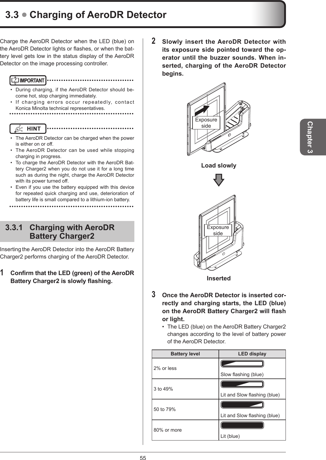
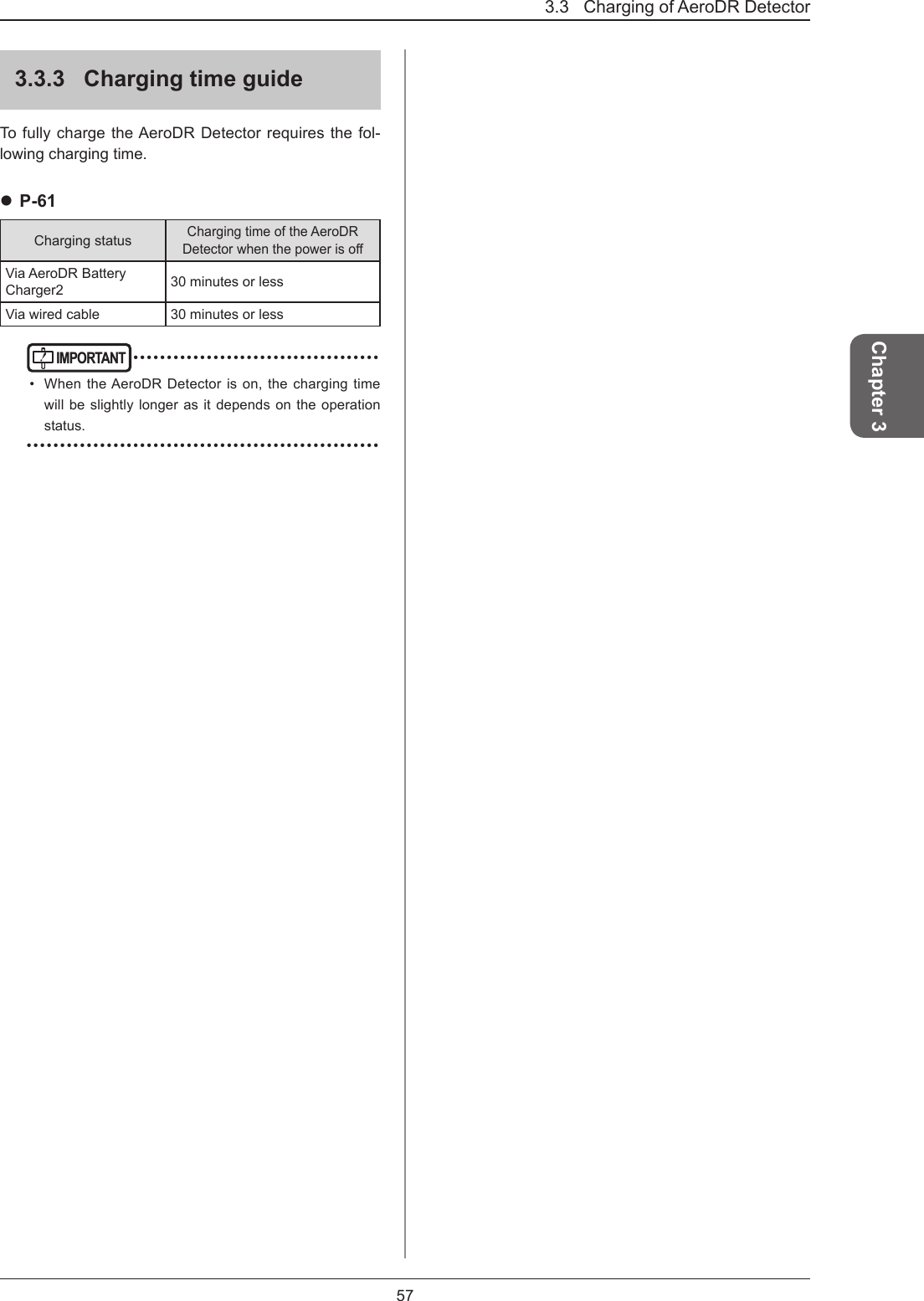
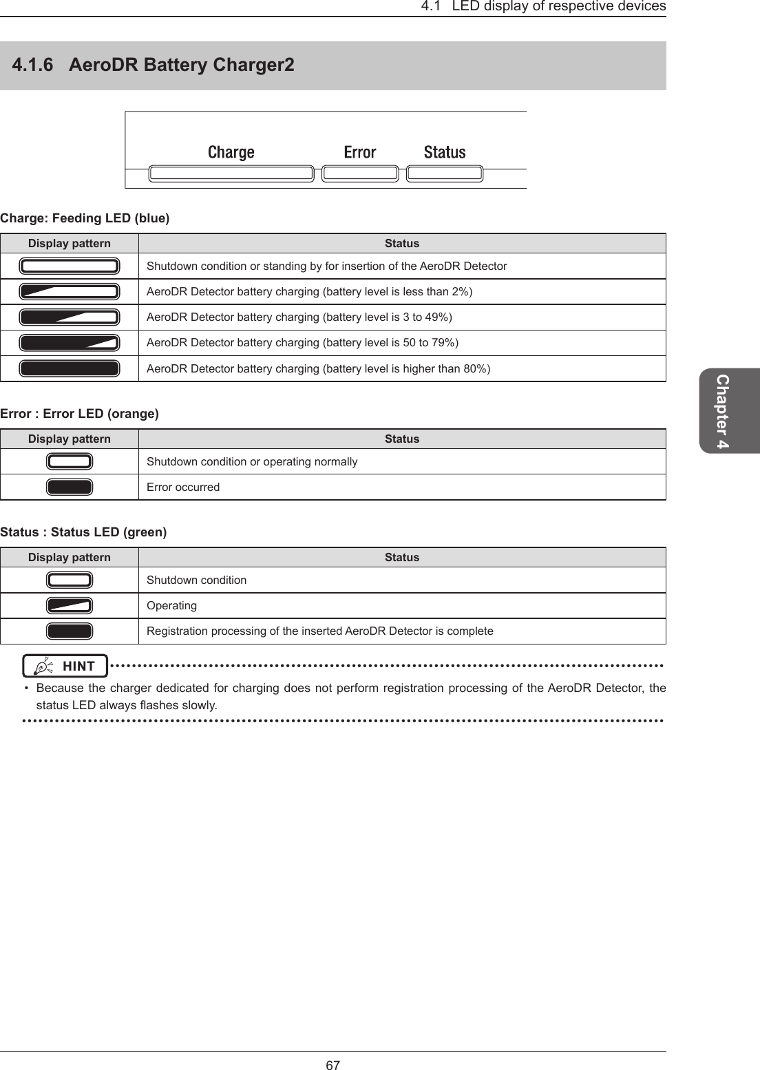

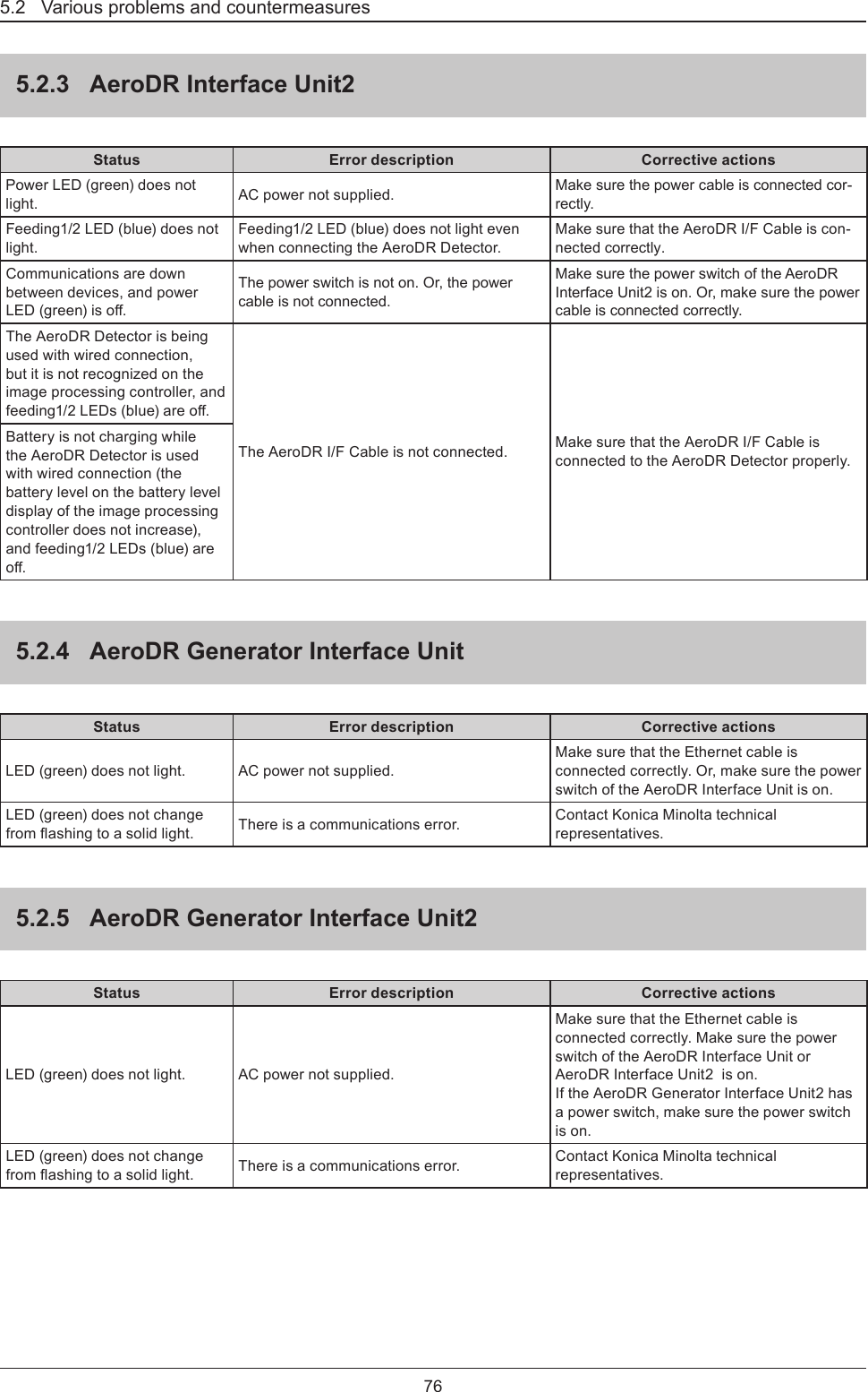

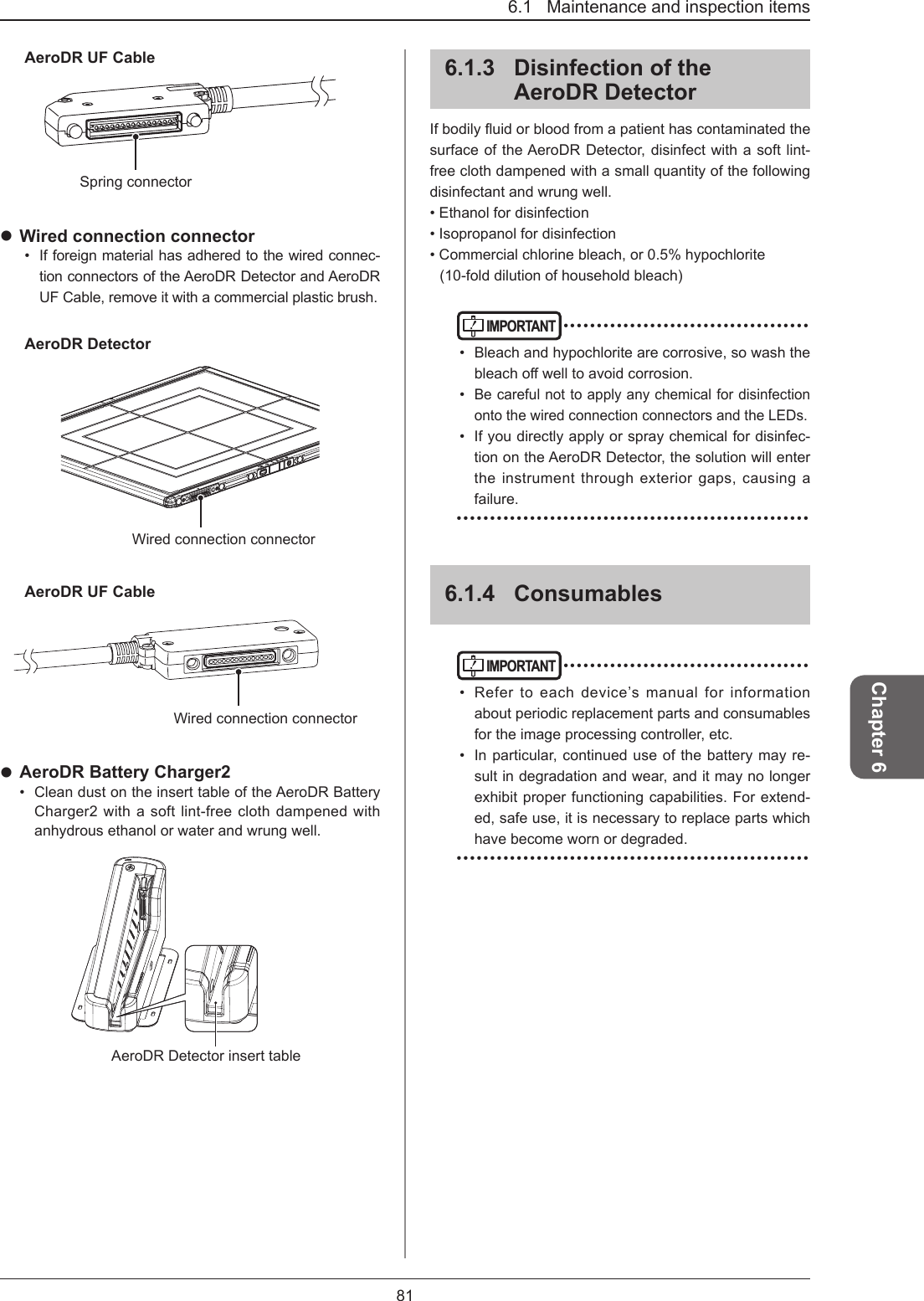

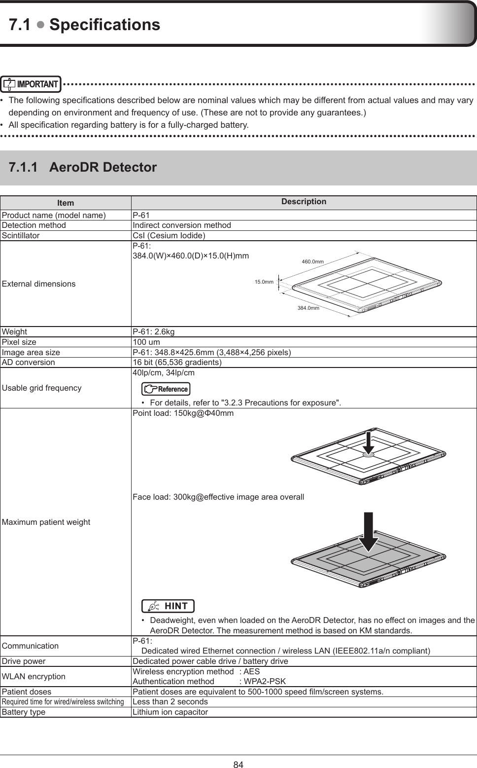
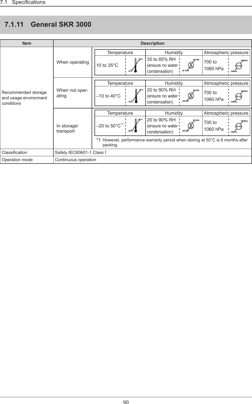
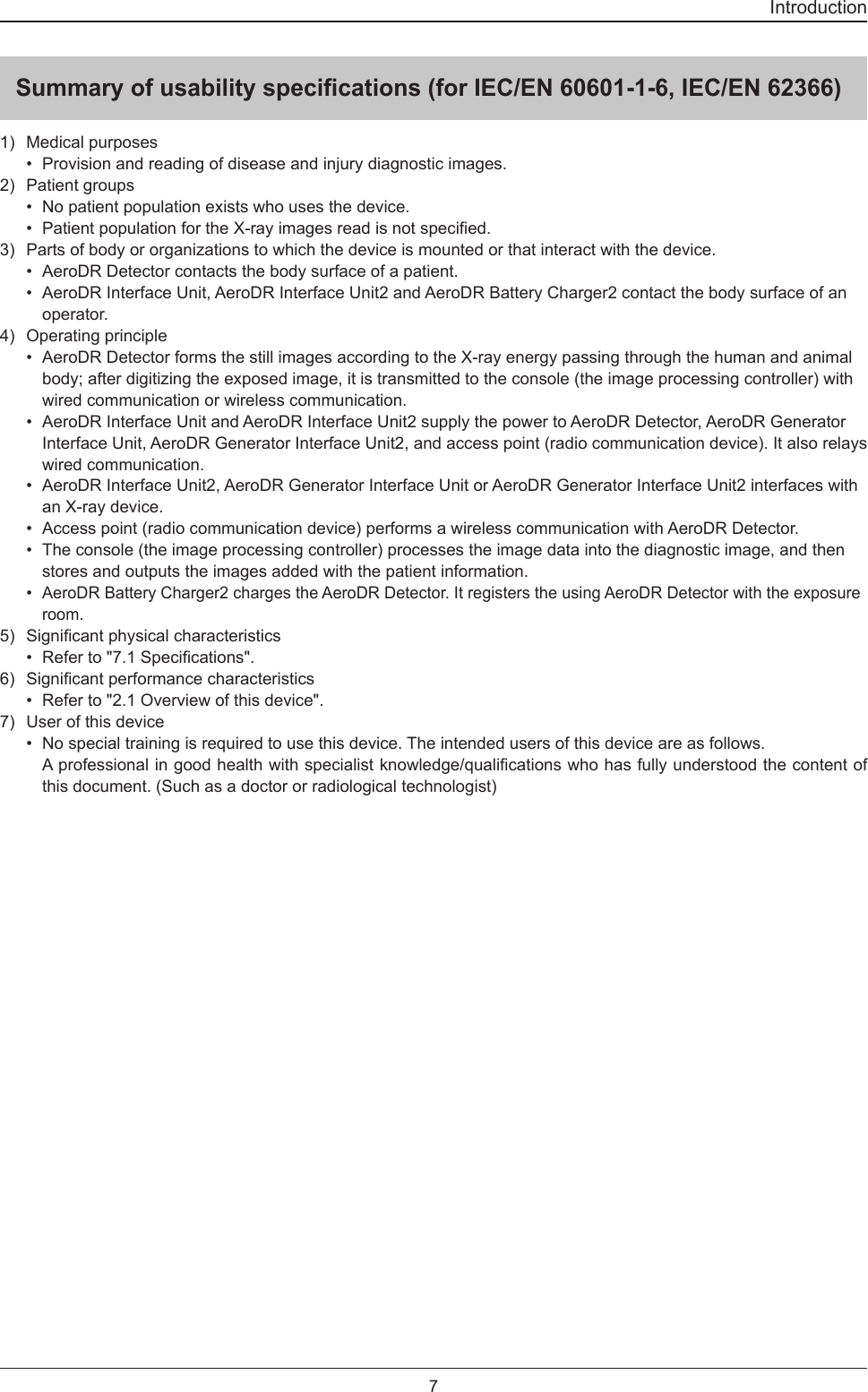
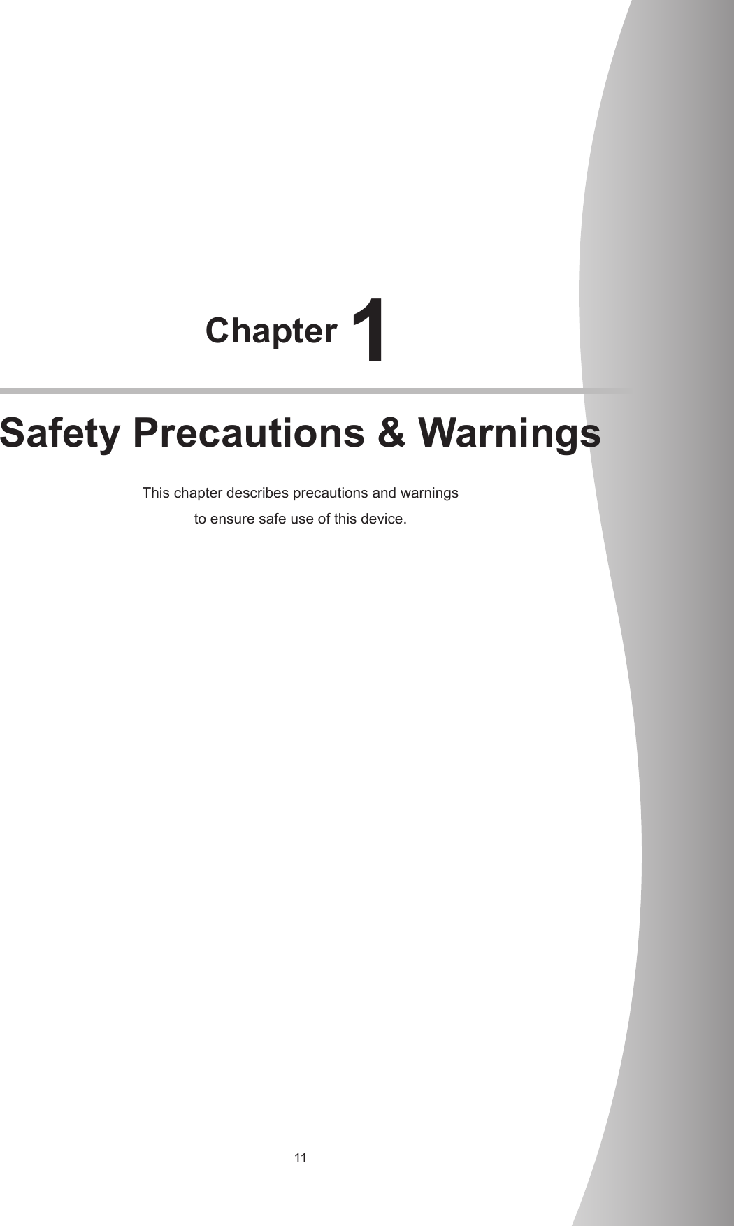
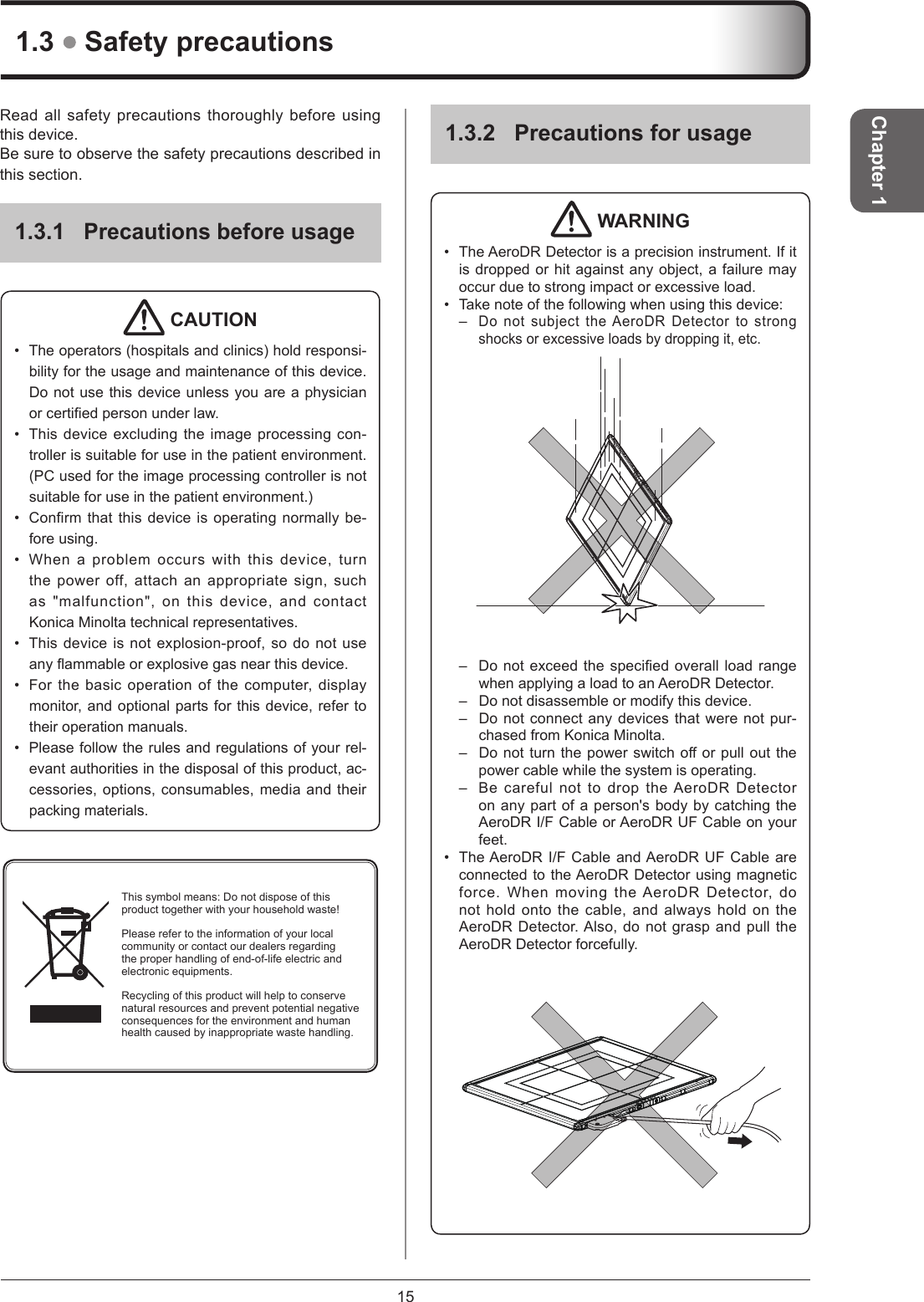
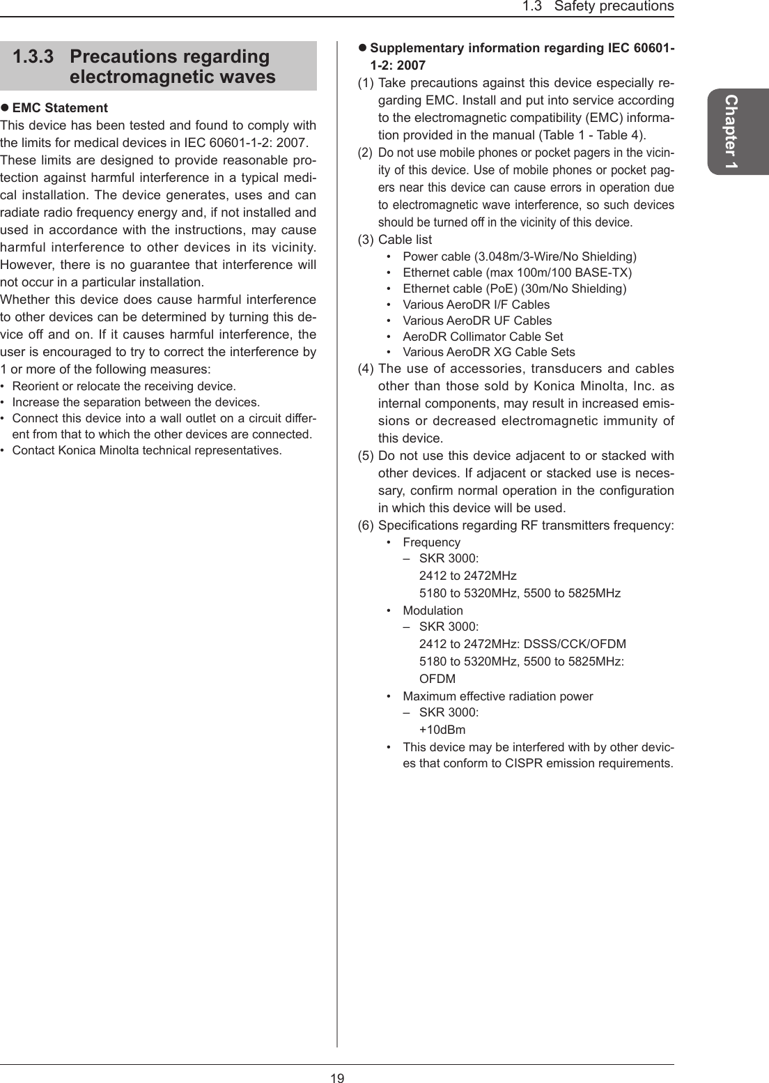
![857.1 SpecicationsChapter 7Item DescriptionBattery charging time empty to fullP-61:30 minutes or less (When using the AeroDR Battery Charger2)30 minutes or less (When using the dedicated wired cable)Number of exposable images P-61: 100[um]: 215 images/6.0 hours 200[um]: 285 images/8.0 hoursBattery duration in standby status P-61: Approx. 11 hoursBattery expected lifetime Above the AeroDR Detector Service life](https://usermanual.wiki/KONICA-MINOLTA/SKR3000P6/User-Guide-3202428-Page-85.png)