KP Electronic Systems KPBSR100N BASE STATION RADIO User Manual DI100
KP Electronic Systems Ltd BASE STATION RADIO DI100
UserManual.wiki
>
KP Electronic Systems
>
KPBSR100N User Manual
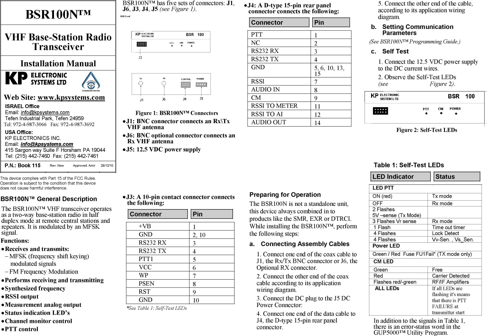
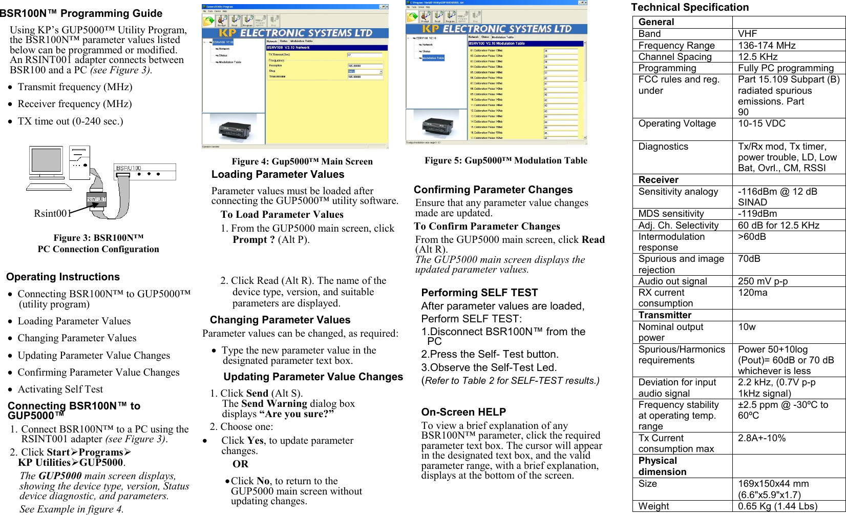
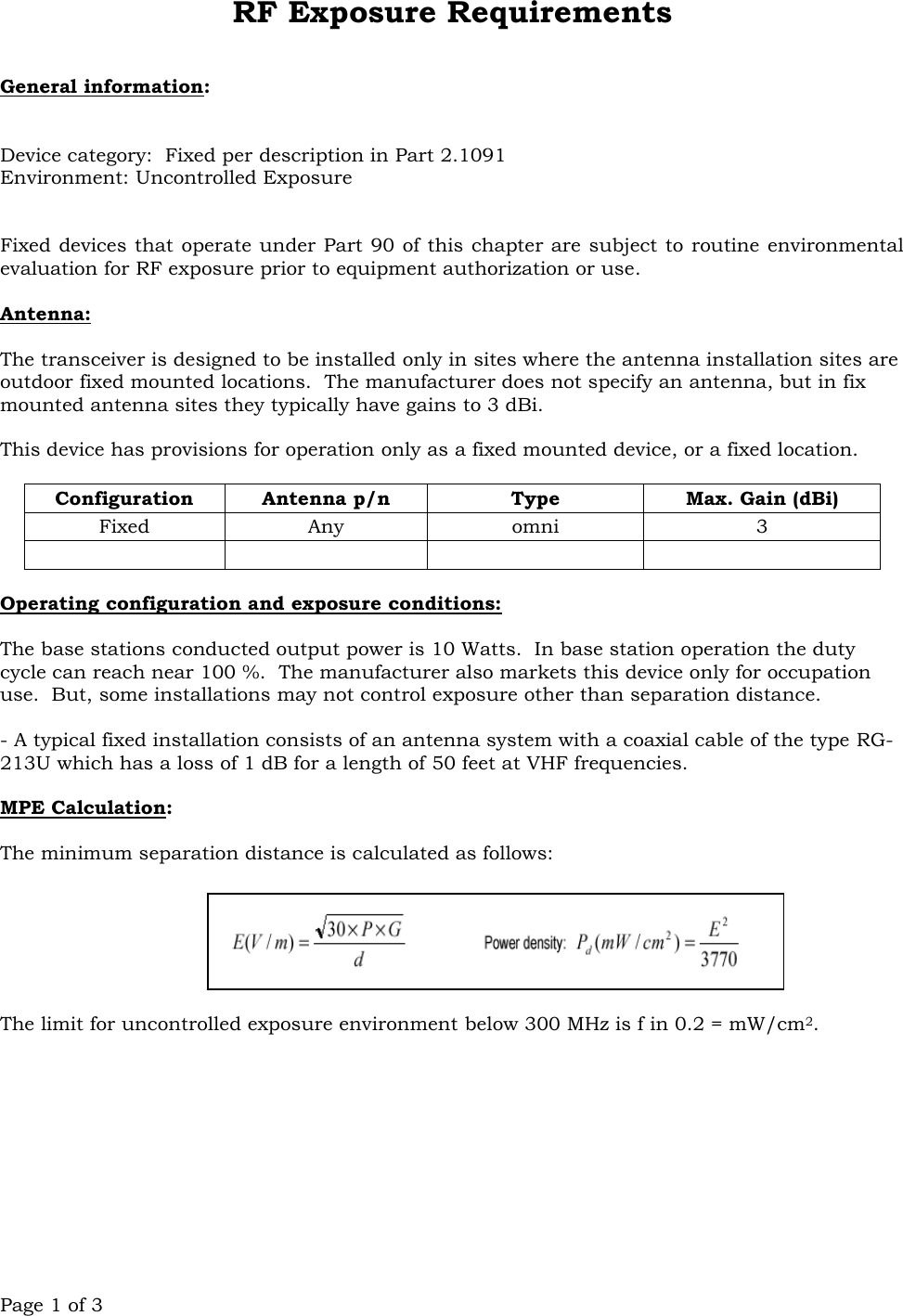
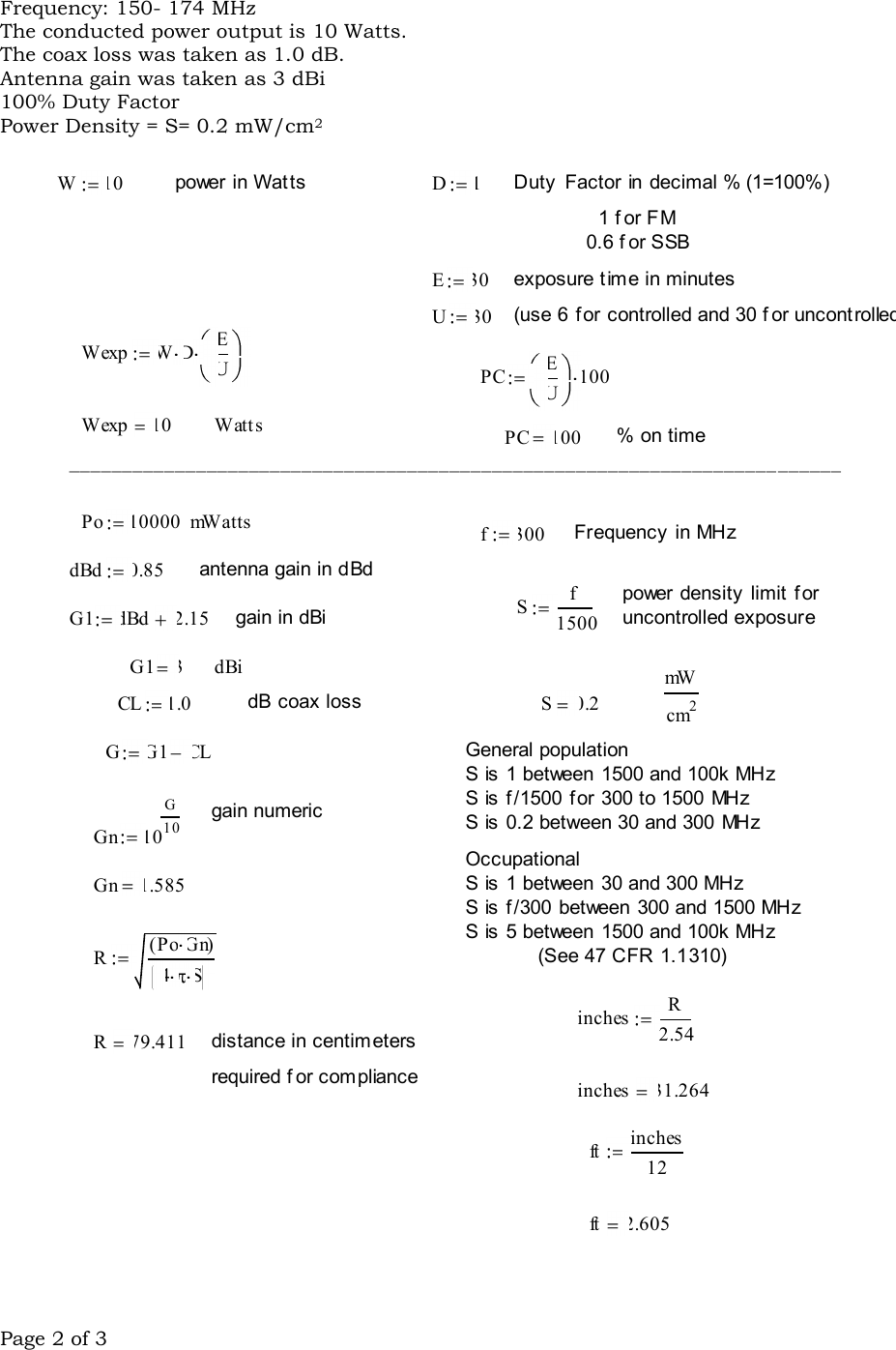
INSTALLATION MANUAL
Navigation menu
Upload a User Manual
Namespaces
Wiki Guide
HTML
PDF
Info
Views
User Manual
Discussion / Help
Navigation