KP Electronic Systems KPBSR100N BASE STATION RADIO User Manual DI100
KP Electronic Systems Ltd BASE STATION RADIO DI100
INSTALLATION MANUAL
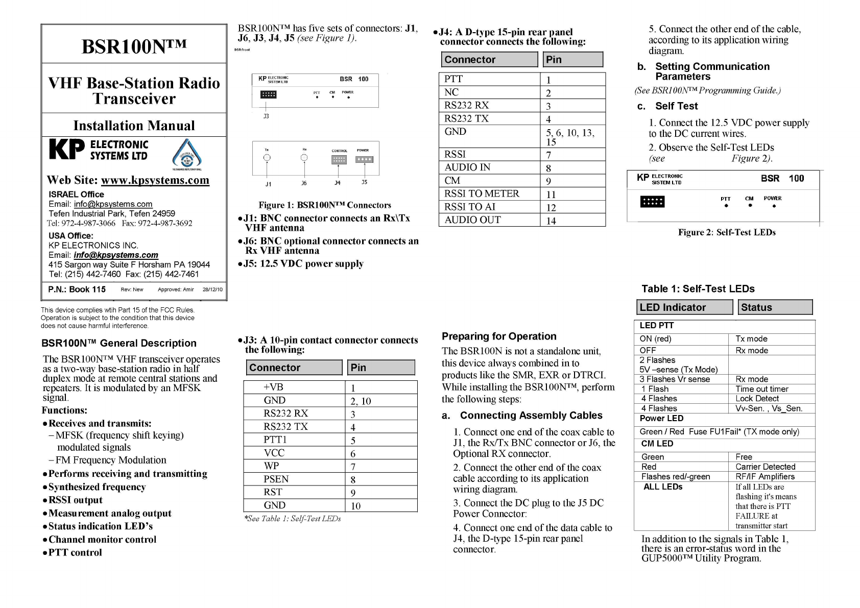
BSR100N™ Programming Guide
Using KP’s GUP5000™ Utility Program,
the BSR100N™ parameter values listed
below can be programmed or modified.
An RSINT001 adapter connects between
BSR100 and a PC (see Figure 3).
Transmit frequency (MHz)
Receiver frequency (MHz)
TX time out (0-240 sec.)
Figure 3: BSR100N™
PC Connection Configuration
Operating Instructions
Connecting BSR100N™ to GUP5000™
(utility program)
Loading Parameter Values
Changing Parameter Values
Updating Parameter Value Changes
Confirming Parameter Value Changes
Activating Self Test
Connecting BSR100N™ to
GUP5000™
1. Connect BSR100N™ to a PC using the
RSINT001 adapter (see Figure 3).
2. Click StartPrograms
KP UtilitiesGUP5000.
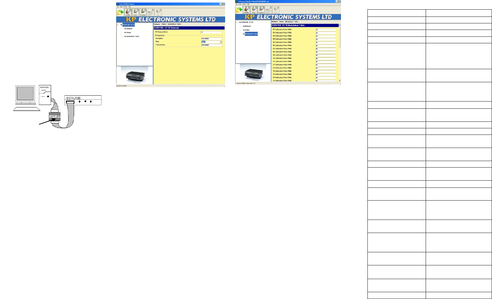
The GUP5000 main screen displays,
showing the device type, version, Status
device diagnostic, and parameters.
See Example in figure 4.
Figure 4: Gup5000™ Main Screen
Loading Parameter Values
Parameter values must be loaded after
connecting the GUP5000™ utility software.
To Load Parameter Values
1. From the GUP5000 main screen, click
Prompt ? (Alt P).
2. Click Read (Alt R). The name of the
device type, version, and suitable
parameters are displayed.
Changing Parameter Values
Parameter values can be changed, as required:
Type the new parameter value in the
designated parameter text box.
Updating Parameter Value Changes
1. Click Send (Alt S).
The Send Warning dialog box
displays “Are you sure?”
2. Choose one:
Click Yes, to update parameter
changes.
OR
Click No, to return to the
GUP5000 main screen without
updating changes.
Figure 5: Gup5000™ Modulation Table
Confirming Parameter Changes
Ensure that any parameter value changes
made are updated.
To Confirm Parameter Changes
From the GUP5000 main screen, click Read
(Alt R).
The GUP5000 main screen displays the
updated parameter values.
Performing SELF TEST
After parameter values are loaded,
Perform SELF TEST:
1.Disconnect BSR100N™ from the
PC
2.Press the Self- Test button.
3.Observe the Self-Test Led.
(Refer to Table 2 for SELF-TEST results.)
On-Screen HELP
To view a brief explanation of any
BSR100N™ parameter, click the required
parameter text box. The cursor will appear
in the designated text box, and the valid
parameter range, with a brief explanation,
displays at the bottom of the screen.
Technical Specification
General
VHF
Band
136-174 MHz
Frequency Range
12.5 KHz
Channel Spacing
Fully PC programming
Programming
Part 15.109 Subpart (B)
radiated spurious
emissions. Part
90
FCC rules and reg.
under
10-15 VDC
Operating Voltage
Tx/Rx mod, Tx timer,
power trouble, LD, Low
Bat, Ovrl., CM, RSSI
Diagnostics
Receiver
-116dBm @ 12 dB
SINAD
Sensitivity analogy
-119dBm
MDS sensitivity
60 dB for 12.5 KHz
Adj. Ch. Selectivity
>60dB
Intermodulation
response
70dB
Spurious and image
rejection
250 mV p-p
Audio out signal
120ma
RX current
consumption
Transmitter
10w
Nominal output
power
Power 50+10log
(Pout)= 60dB or 70 dB
whichever is less
Spurious/Harmonics
requirements
2.2 kHz, (0.7V p-p
1kHz signal)
Deviation for input
audio signal
±2.5 ppm @ -30ºC to
60ºC
Frequency stability
at operating temp.
range
2.8A+-10%
Tx Current
consumption max
Physical
dimension
169x150x44 mm
(6.6"x5.9"x1.7)
Size
0.65 Kg (1.44 Lbs)
Weight
Rsint001
Page 1 of 3
RF Exposure Requirements
General information:
Device category: Fixed per description in Part 2.1091
Environment: Uncontrolled Exposure
Fixed devices that operate under Part 90 of this chapter are subject to routine environmental
evaluation for RF exposure prior to equipment authorization or use.
Antenna:
The transceiver is designed to be installed only in sites where the antenna installation sites are
outdoor fixed mounted locations. The manufacturer does not specify an antenna, but in fix
mounted antenna sites they typically have gains to 3 dBi.
This device has provisions for operation only as a fixed mounted device, or a fixed location.
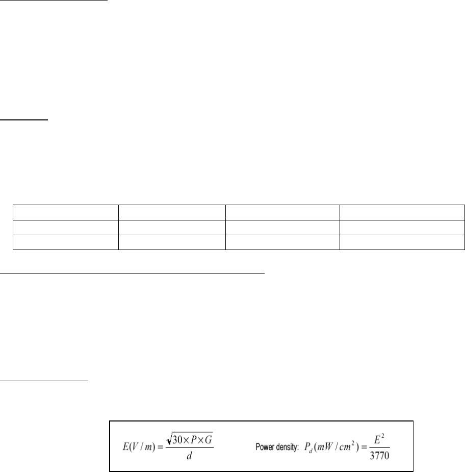
Configuration
Antenna p/n
Type
Max. Gain (dBi)
Fixed
Any
omni
3
Operating configuration and exposure conditions:
The base stations conducted output power is 10 Watts. In base station operation the duty
cycle can reach near 100 %. The manufacturer also markets this device only for occupation
use. But, some installations may not control exposure other than separation distance.
- A typical fixed installation consists of an antenna system with a coaxial cable of the type RG-
213U which has a loss of 1 dB for a length of 50 feet at VHF frequencies.
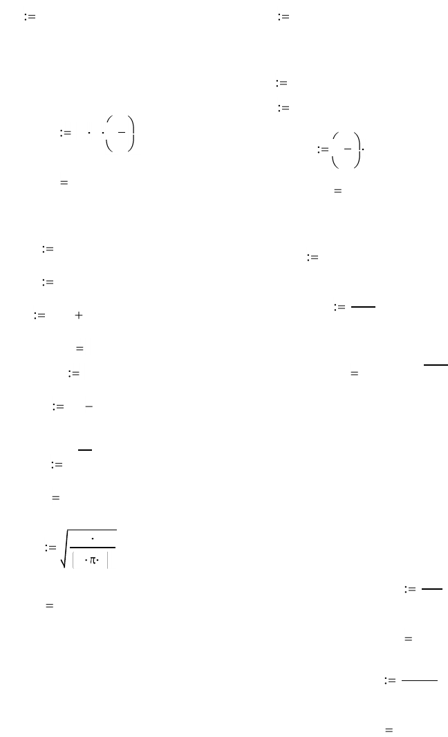
MPE Calculation:
The minimum separation distance is calculated as follows:
The limit for uncontrolled exposure environment below 300 MHz is f in 0.2 = mW/cm2.
Page 2 of 3
Frequency: 150- 174 MHz
The conducted power output is 10 Watts.
The coax loss was taken as 1.0 dB.
Antenna gain was taken as 3 dBi
100% Duty Factor
Power Density = S= 0.2 mW/cm2
Sf
1500
G1 dBd 2.15 gain in dBi
G1 3 dBi mW
cm2
CL 1.0 dB coax loss S 0.2
GG1 CL General population
S is 1 between 1500 and 100k MHz
S is f /1500 f or 300 to 1500 MHz
S is 0.2 between 30 and 300 MHz
gain numeric
Gn 10
G
10
Occupational
S is 1 between 30 and 300 MHz
S is f /300 between 300 and 1500 MHz
S is 5 between 1500 and 100k MHz
(See 47 CFR 1.1310)
Gn 1.585
RPo Gn( )
4 S
inches R
2.54
R 79.411 distance in centimeters
required f or compliance inches 31.264
ft inches
12
ft 2.605
W10 power in Watts D 1 Duty Factor in decimal % (1=100%)
1 f or FM
0.6 f or SSB
E30 exposure t ime in minutes
U30 (use 6 for controlled and 30 f or uncontrolled)
Wexp W D E
UPC E
U100
Wexp 10 Watt s PC 100 % on time
_________________________________________________________________________
Po 10000 mWatts f300 Frequency in MHz
dBd 0.85 antenna gain in dBd
power density limit for
uncontrolled exposure

Page 3 of 3
Conclusion:
For a transmitter operating with the above criteria the separation distance should be
no less than 80 cm or 2.6 ft between the antenna, including any radiating structure,
and any persons when normally operated. Other operating conditions should follow a
procedure like that shown above and following the guidelines such as those in FCC
document OET-65.