KROHNE 70 Level Radar User Manual JH5 70 Manual
Krohne America Inc Level Radar JH5 70 Manual
UserManual.wiki
>
KROHNE
>
70 User Manual
>
Manual
Contents
1.
Manual
2.
Manual addendum
Manual
Navigation menu
Upload a User Manual
Namespaces
Wiki Guide
HTML
PDF
Info
Views
User Manual
Discussion / Help
Navigation
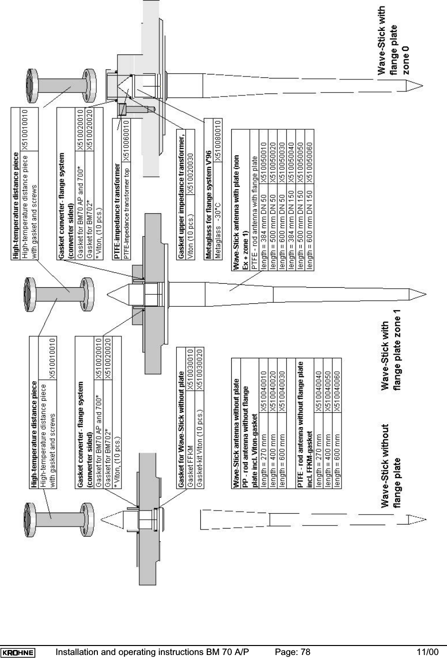
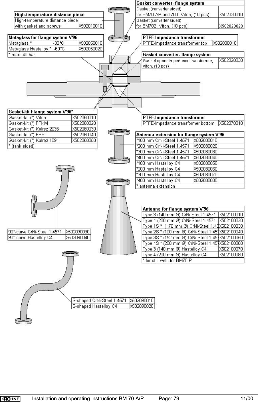
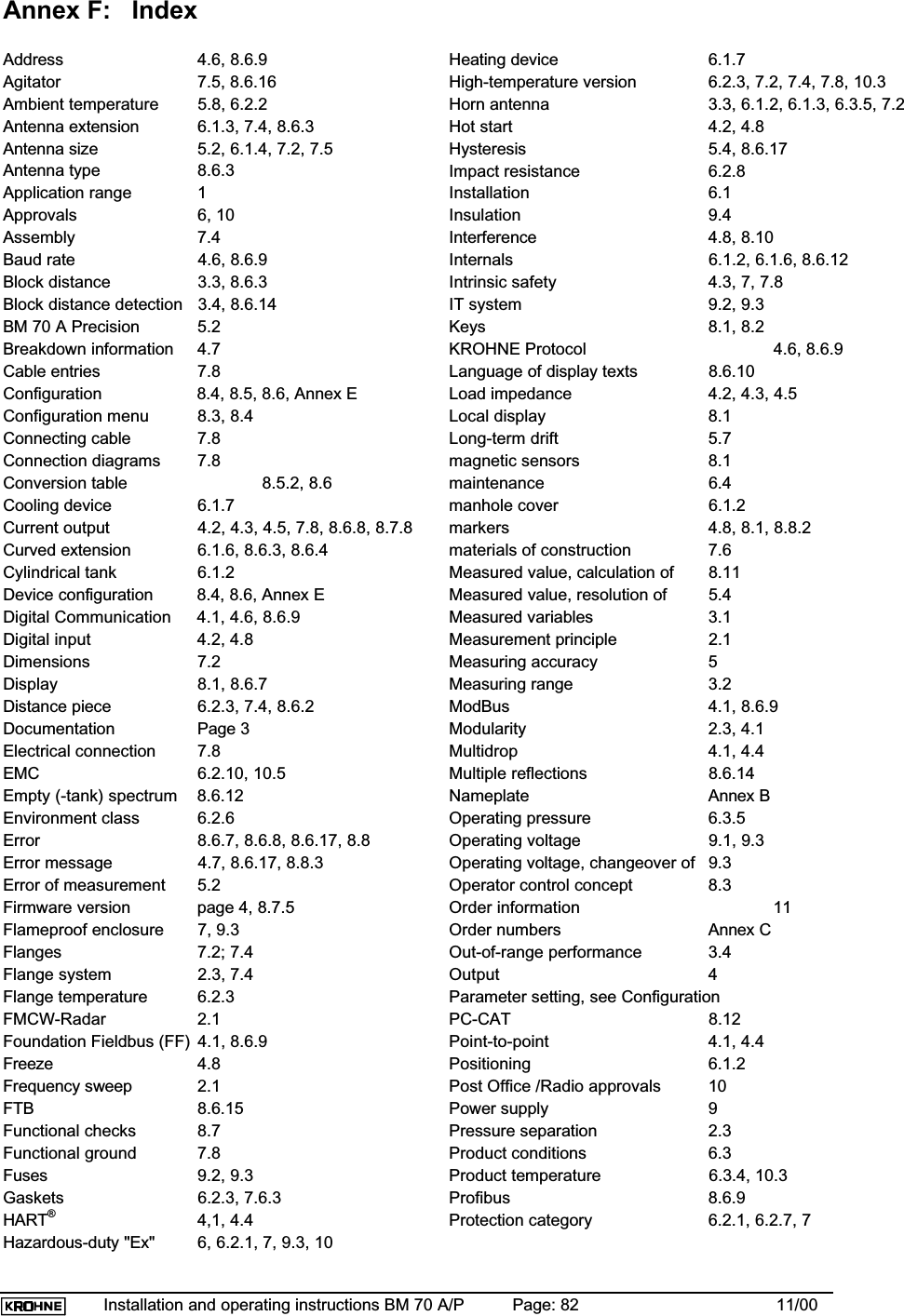
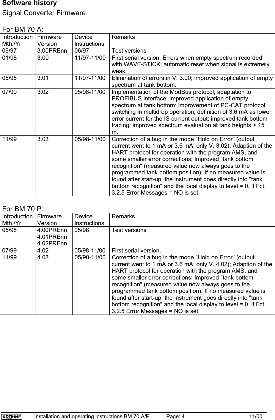
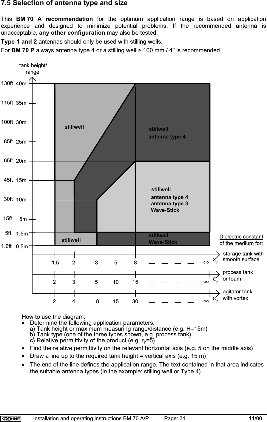
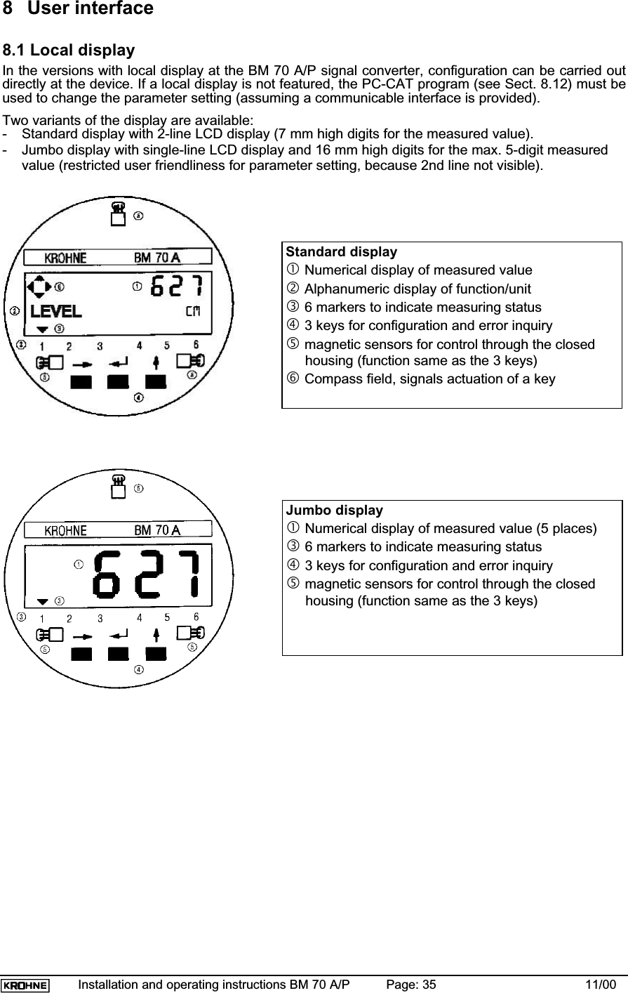
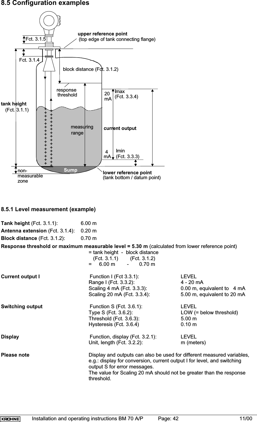
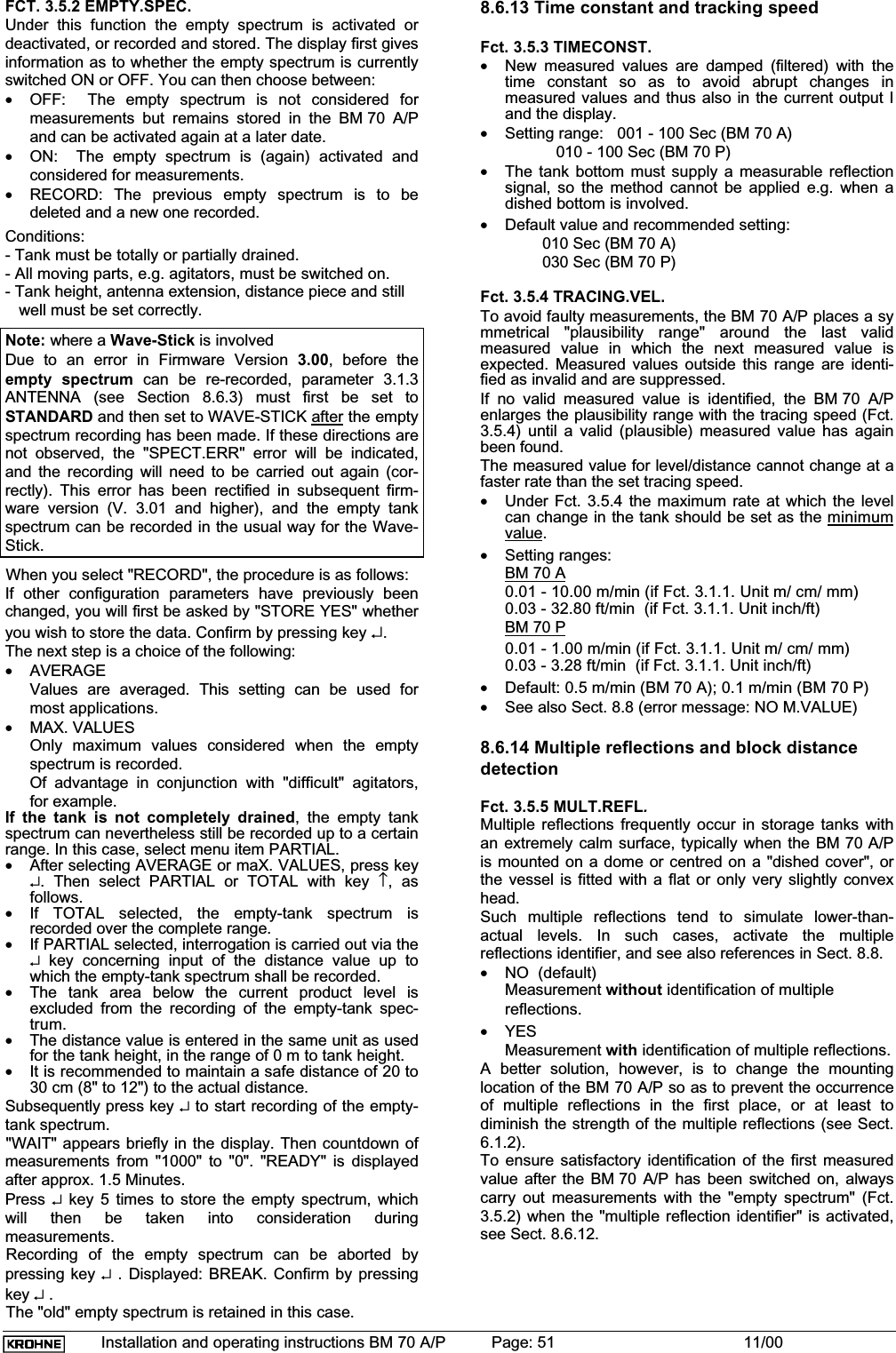
![BM 70 A/P Montage- und Betriebsanleitung Seite: 2 11/00Contents:General advice on safety ................................3Product liability and warranty .........................3Items included with supply ..............................3Software history ..............................................41. Range of application ................................62. Mode of operation and system structure.62.1 Operating principle ...................................62.2 Signal processing (digital) .........................72.3 Modularity (signal converter, flange, antenna)....................................................73. Input...........................................................83.1 Measured variable (distance, level, volume, reflection) ....................................83.2 Measuring range [0.5-35/40 m (1.64-115/131 ft)] .....................................83.3 Block distance...........................................83.4 Out-of-range performance.........................84. Output........................................................94.1 Variants.....................................................94.2 Ex-e current output HART®....................104.3 Ex-i current output HART® (type of protection: Ex de [ia]) ................104.4 HART® communication............................114.5 Current output (non-communicable) .......114.6 Digital interface RS 485 .........................114.7 Breakdown signal ....................................134.8 Digital input.............................................135. Measuring accuracy................................145.1 Reference conditions...............................145.2 Error of measurement ............................145.3 Repeatability ...........................................155.4 Measured value resolution/hysteresis .....155.5 Transient recovery time ..........................165.6 Turn-on drift / turn-on characteristics ......165.7 Long-term drift .......................................165.8 Effect of ambient temperature ................166. Operating conditions .............................176.1 Installation conditions .............................176.2 Ambient conditions..................................256.3 Product conditions...................................266.4 Maintenance ......... .................................277. Design......................................................287.1 Models ..... .............................................287.2 Dimensions and weights .........................297.3 Replacement of the signal converter .......307.4 Field assembly ........................................307.5 Selection of antenna type and size..............317.6 Materials of construction .........................327.7 Process connection .................................327.8 Electrical connection ...............................337.9 Terminating resistor for the RS 485 interface .....................................348. User interface ..........................................358.1 Local display .........................................358.2 Function of the keys ...............................368.3 Operator control concept........................378.4 Table fo settable functions (Version 3.00, 3.03, 4.02, 4.03) .............398.5 Configuration examples..........................428.6 Description of functions ..........................448.7 Functional checks...................................558.8 Pointers and error messages duringmeasurements.......................................568.9 Messages on start-up.............................588.10 Faults and symptoms during start-upand measurement .................................588.11 Calculation of the measured value .......618.12 User program PC-CAT for Windows .........................................629. Power supply ..........................................639.1 Options, technical data...........................639.2 Fuses ....................................................639.3 Changeover of operating voltage andreplacement of fuses .............................639.4 Advice on safety.....................................6410. Certificates and approvals....................6610.1 Hazardous-duty approvals.....................6610.2 Other approvals and certificates ...........6610.3 Explosion proof acc. to ATEX ...............6710.4 Radio approval .....................................6810.5 CE manufacturer’s declaration...............6911. Order information .................................7012. External standards, codes and directives ..............................................7113. Quality assurance .................................71AnnexAnnex A: Technical Data ............................72Annex B: Type code / nameplates...............74Annex C: Spare parts .................................77Annex D: Signed declaration to accompany a device returned to KROHNE ....80Annex E: Table on documentation of device configuration....................81Annex F: Index............................................82](https://usermanual.wiki/KROHNE/70.Manual/User-Guide-236910-Page-2.png)
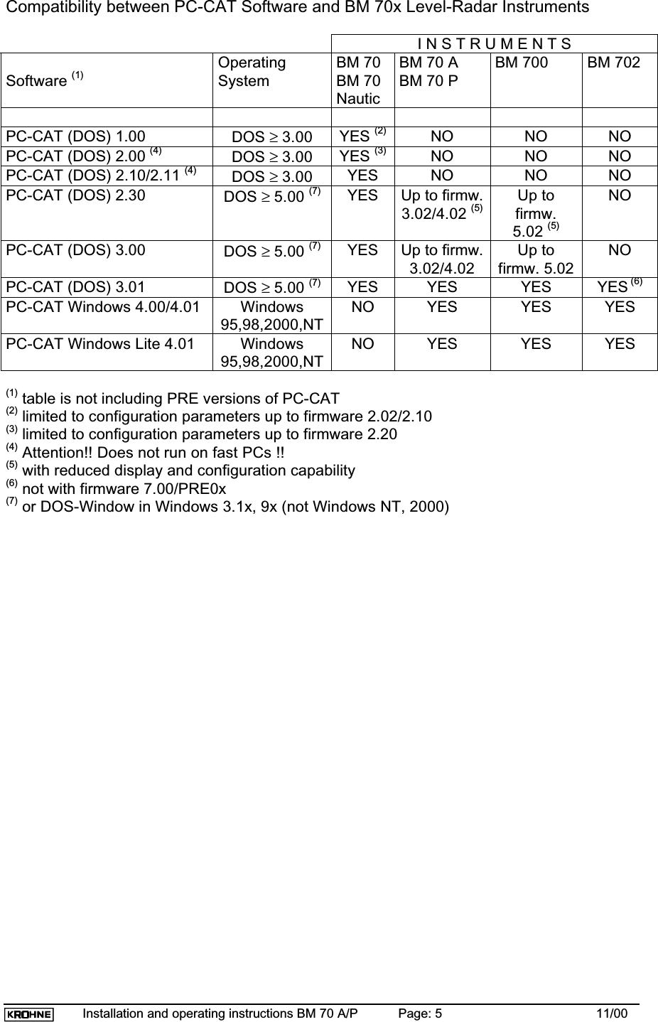
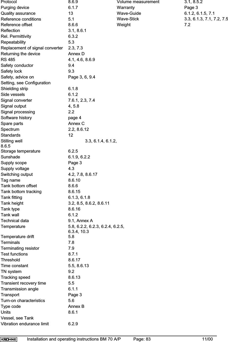
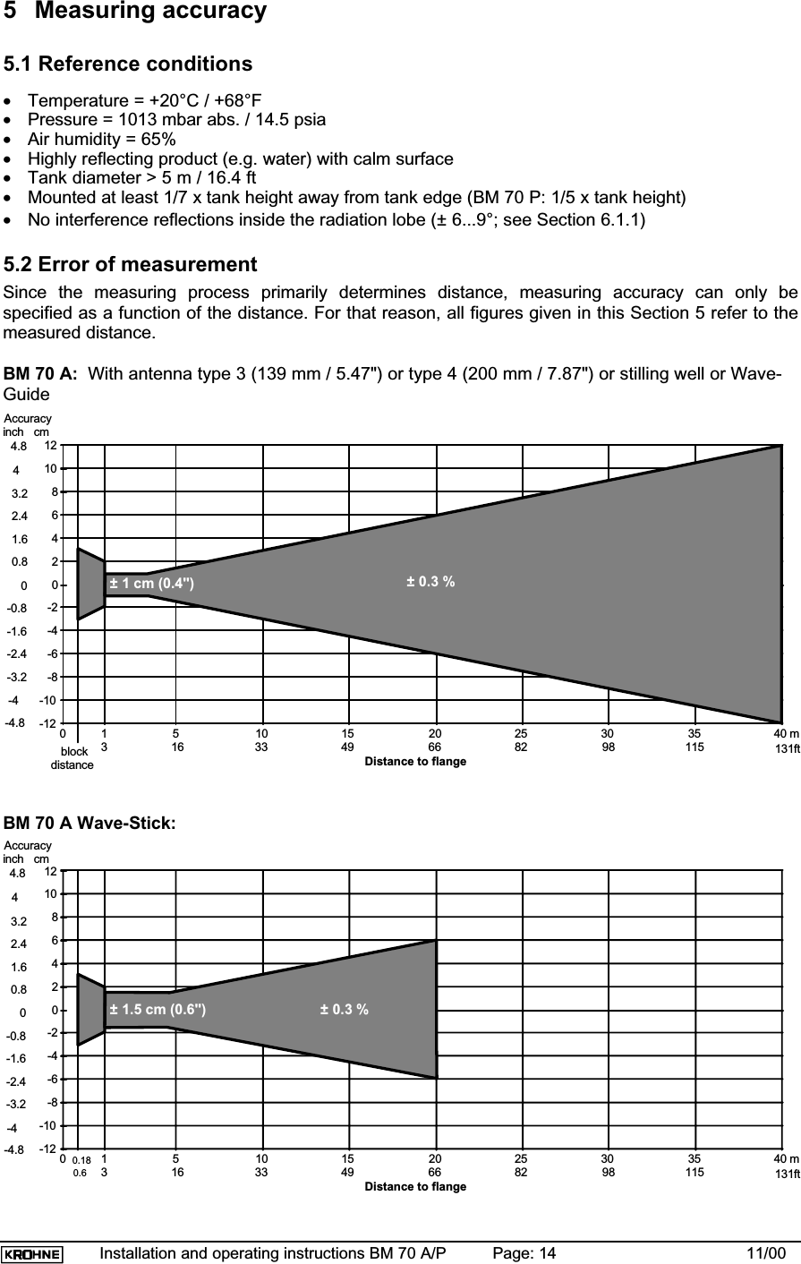
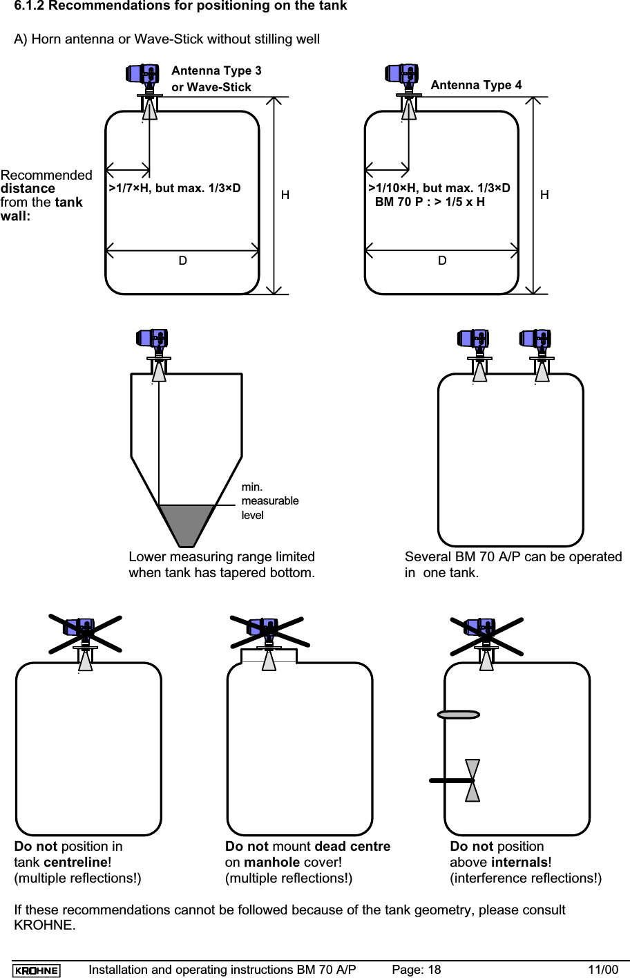
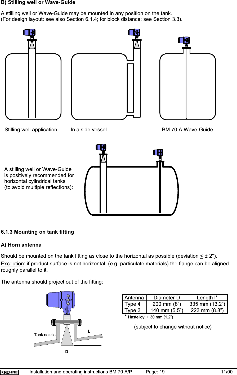
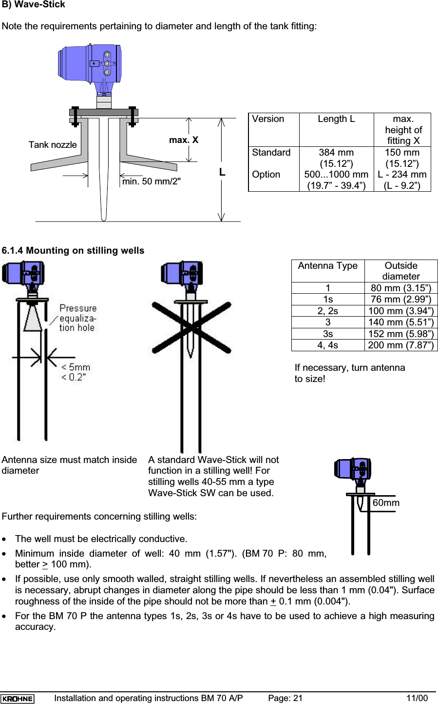
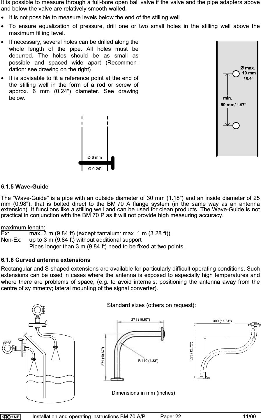
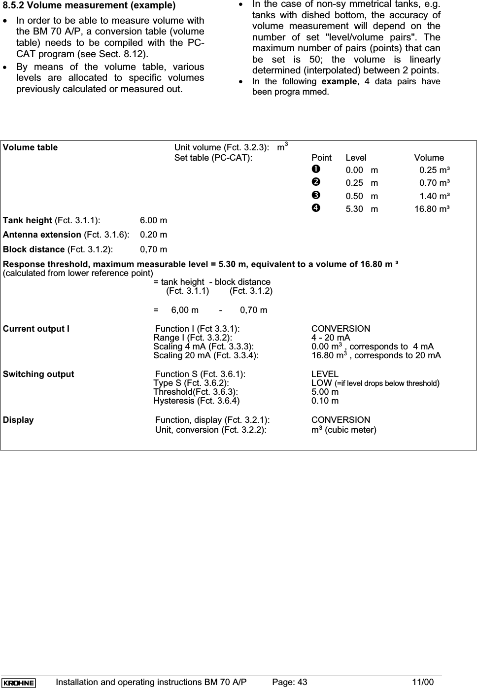
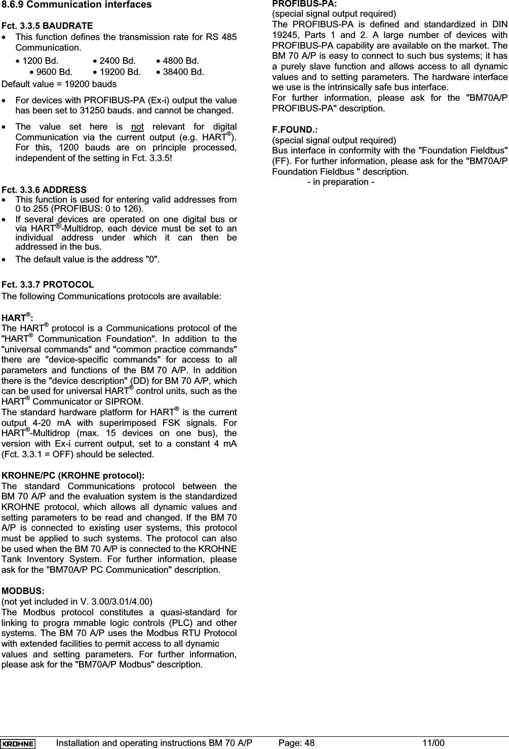
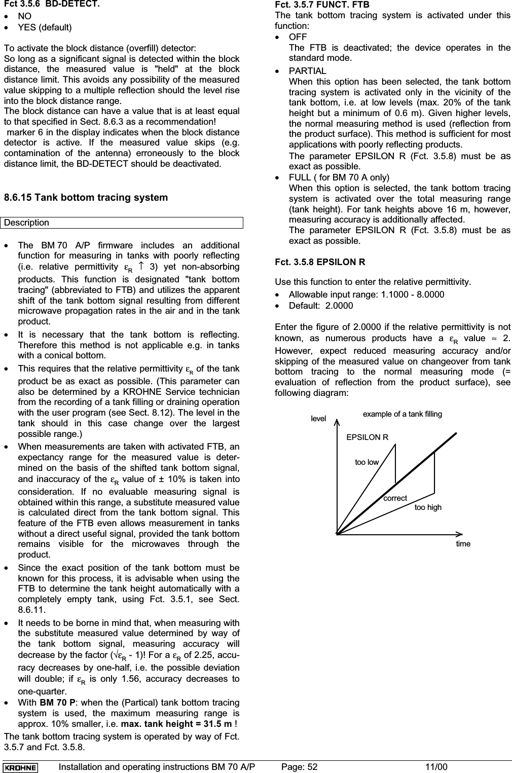
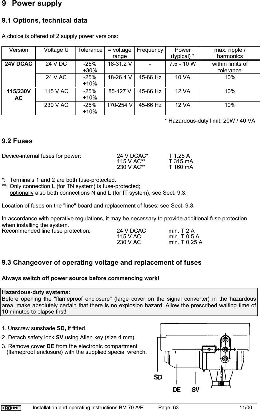
![Installation and operating instructions BM 70 A/P Page: 8 11/003 Input3.1 Measured variable (distance, level, volume, reflection)The primary measured variable is the distance between a reference point (as standard: tank mountingflange) and a reflecting surface (e.g. surface of the liquid).The filling level is determined by allowing arithmetically for the entered tank height.Volume measurements are possible by entering a conversion table (max. 50 points).The strength of the reflected signal can be measured for qualitative assessment of the tank product orits surface.3.2 Measuring range [0.5-35/40 m (1.64-115/131 ft)]Minimum tank height 0.5 m (1.64 ft)Maximum measuring BM 70 A 40 m (131 ft) / optionally 100 m (328 ft)BM 70 A mit Wave-Stick 20 m (65.62 ft)BM 70 P 35 m (115 ft)The useful range will depend on the antenna size, the reflection properties of the tank product, theinstallation position, and the presence of interference reflectors (see Sections 6.1 and 7.5).3.3 Block distanceThe block distance is the minimum measured distance between the mountingflange (reference point) and surface of the tank product.Recommended minimum values: see following sketches.Horn antenna without stilling well:Product surfaceStorage tanks: 10cm/4"; Process tanks: 20cm/8"Antenna size* = Type3: 22cm/8.7"; Type4: 34cm/13"; * Hastelloy: +3cm / 1,2 "Recommended antenna distance:The length of any antenna extension used must be added on!Stilling well / Wave-Guide Wave-StickProductAntenna size * = Type1: 11cm/4";Type2: 15cm/5.5"; Type3: 22cm/8.7"Recommended antenna distance =30 cm / 12"(Wave-Guide: no antenna)* Hastelloy: 3 cm (0.4")Wave-Stick SW: 6cm/2.4"384 mm/15.1"Productmax.200 mmStandard:8"Minimum block distance =Standard: 184 mmNormal: Rod length - 200 mm (7.87")3.4 Out-of-range performanceWhen the level measuring range is exceeded (including flooding) the measured value will stick at the(adjustable) block distance (see Sect. 8.6.14).If the measured value drops below the level range, it will stay put at the set lower range limit (distance= tank height).MaximumlevelBlockdistance](https://usermanual.wiki/KROHNE/70.Manual/User-Guide-236910-Page-8.png)
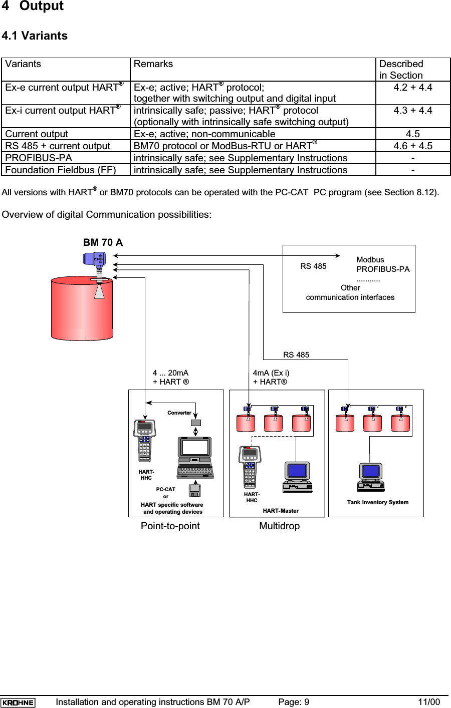
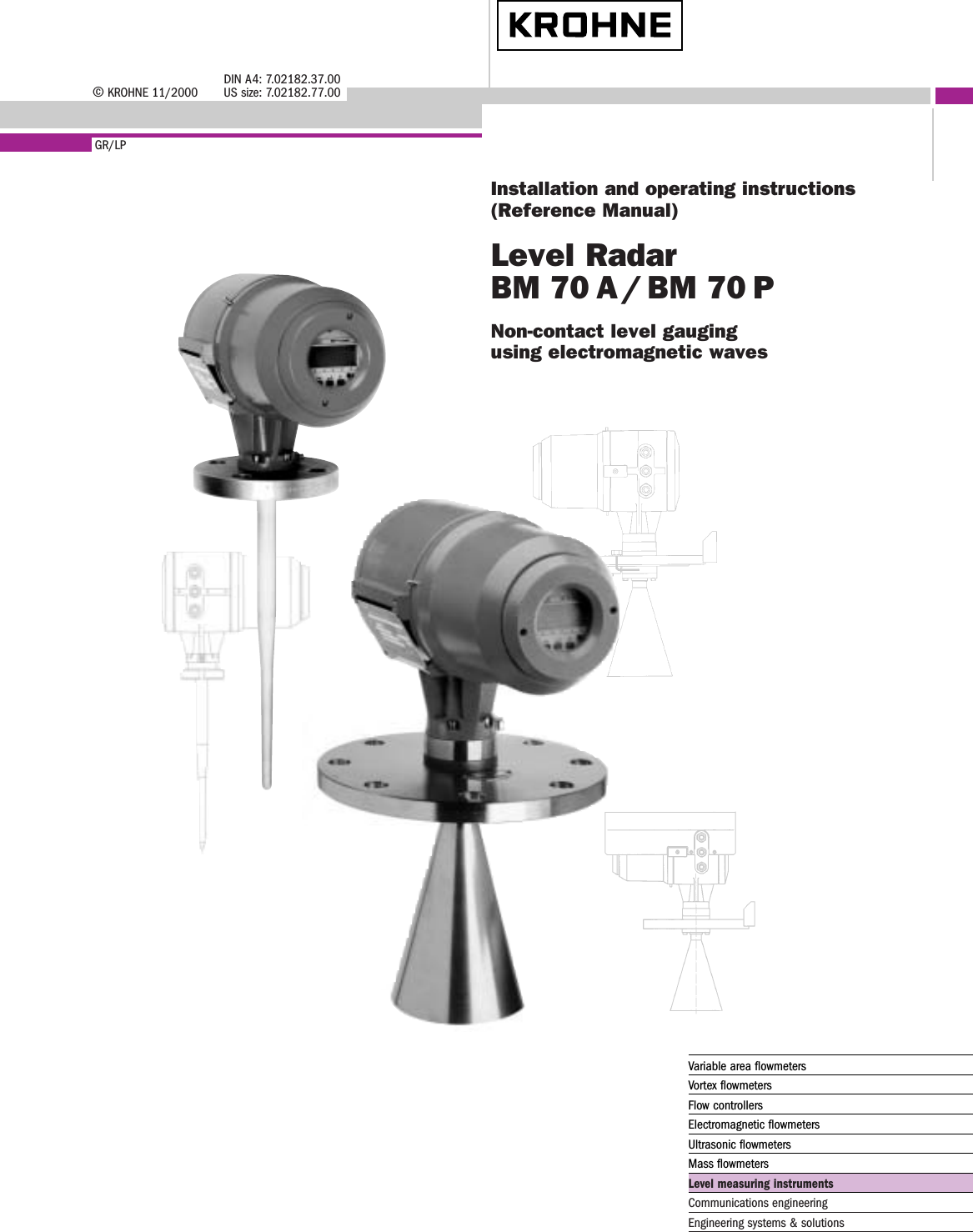
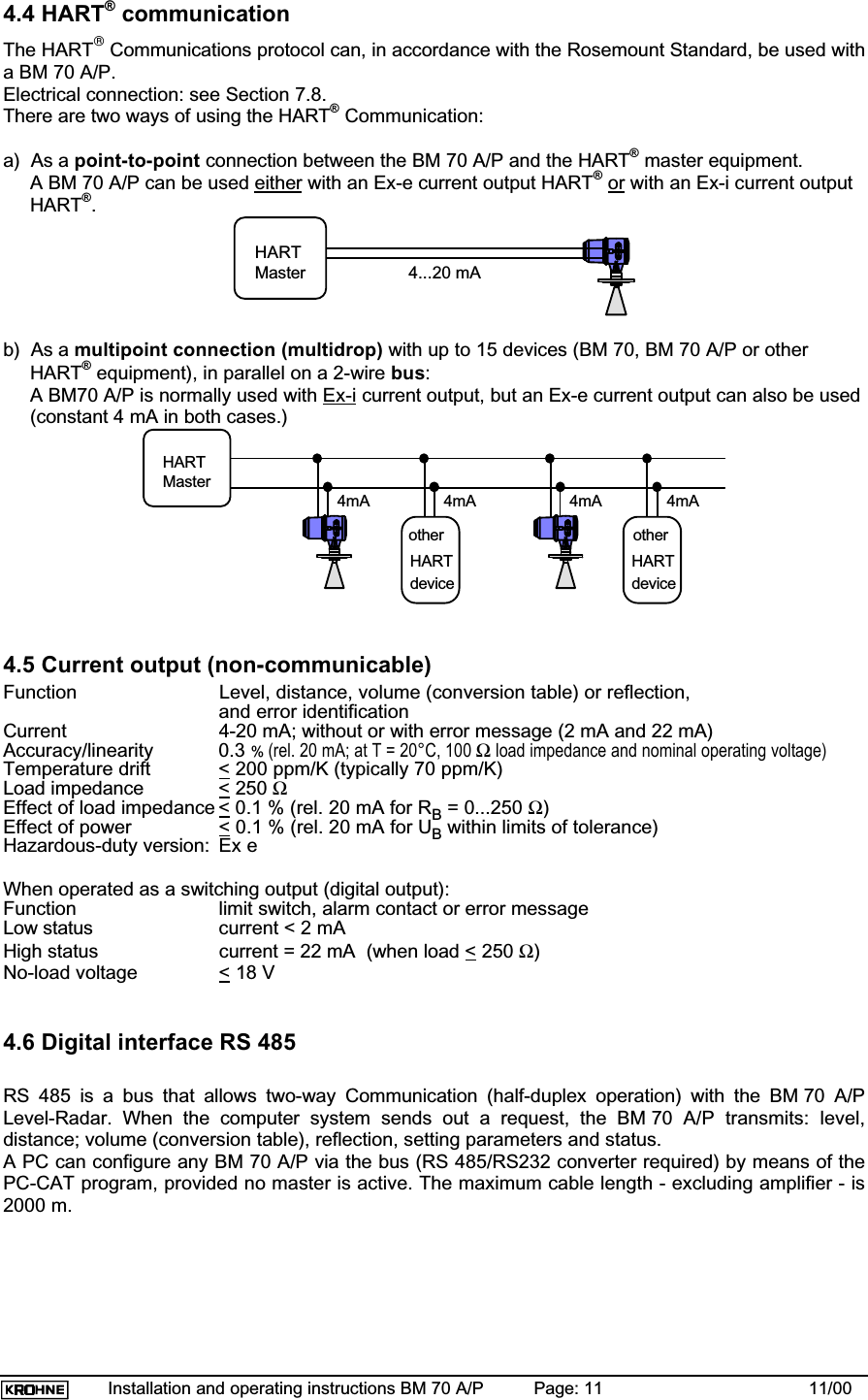
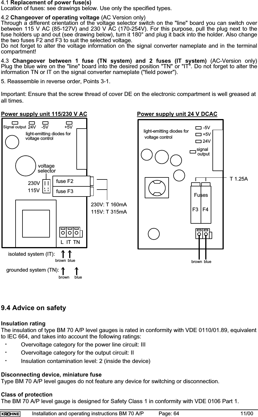
![Installation and operating instructions BM 70 A/P Page: 10 11/004.2 Ex-e current output HART®Function Level, distance, volume (conversion table) or reflection,and error identification;galvanically isolated from digital input and switching outputCurrent 4-20 mA; without or with error message (2 mA and 22 mA)Accuracy/linearity 0.05 % (rel. 20 mA; at T = 20°C, 100Ω load impedance and nominal operating voltage)Temperature drift < 100 ppm/K (typically 30 ppm/K)Load impedance < 500 ΩEffect of load impedance < 0.02 % (rel. 20 mA for RB = 0...500 Ω)Effect of power < 0.02 % (rel. 20 mA for UB within limits of tolerance)Hazardous-duty version: Ex eNote: together with switching output and digital inputDigital input (terminals 81/82):Can be used to suspend the entire measurement procedure, i.e. measurements are "frozen" (standardsetting), or to hot start the device (reprogra mming by KROHNE Service).Applicable voltage: 5...28 V DCInput resistance: > 1 kΩSwitching output (terminals 41/42):Can be progra mmed as a limit switch, alarm contact or error message.The contact is open in the de-energized condition.Operating data: max. 100 mA / 30 V DC or 30 V AC.Internal resistance: < 20 Ω4.3 Ex-i current output HART® (type of protection: Ex de [ia])Function Level, distance, volume (conversion table) or reflection;and error identification;passive output (current sink)Current 4-20 mA; without or with error message (3.6 mA / 22 mA);4 mA constant, adjustable for HART-MultidropTemperature drift < 100 ppm/K (typically 30 ppm/K)Accuracy/linearity 0.05 % (rel. 20 mA; at T = 20°C, 10 V supply voltage and nominal operating voltage)Supply voltage U 8-30 V (between terminals 31 and 32)Load impedance < (US - 8V) / 22 mA (US = external supply voltage)Effect of supply voltage < 0.02 % (rel. 20 mA for U = 8...30 V)Effect of power < 0.02 % (rel. 20 mA for UB within limits of tolerance)Note: Digital input not available.Optional switching output (terminals 41/42):can be progra mmed as limit switch, alarm contact or error message.The contact is open in the de-energized condition.Operating data: 6...30 V; ILow < 110 mA; ULow < 2V; IHigh <900 µA (U=30V) and IHigh =200 µA (U=8V)Ex-i safety limitsSignal circuit in type of protection: Intrinsic Safety EEx ia IIC/IIB or EEx ib IIC/IIBfor connection to a certified intrinsically safe circuit with the following peak values:Uo = 30 V; Ik = 250 mAEffective inner capacitance ≈ 0; effective inner inductance ≈ 0](https://usermanual.wiki/KROHNE/70.Manual/User-Guide-236910-Page-10.png)
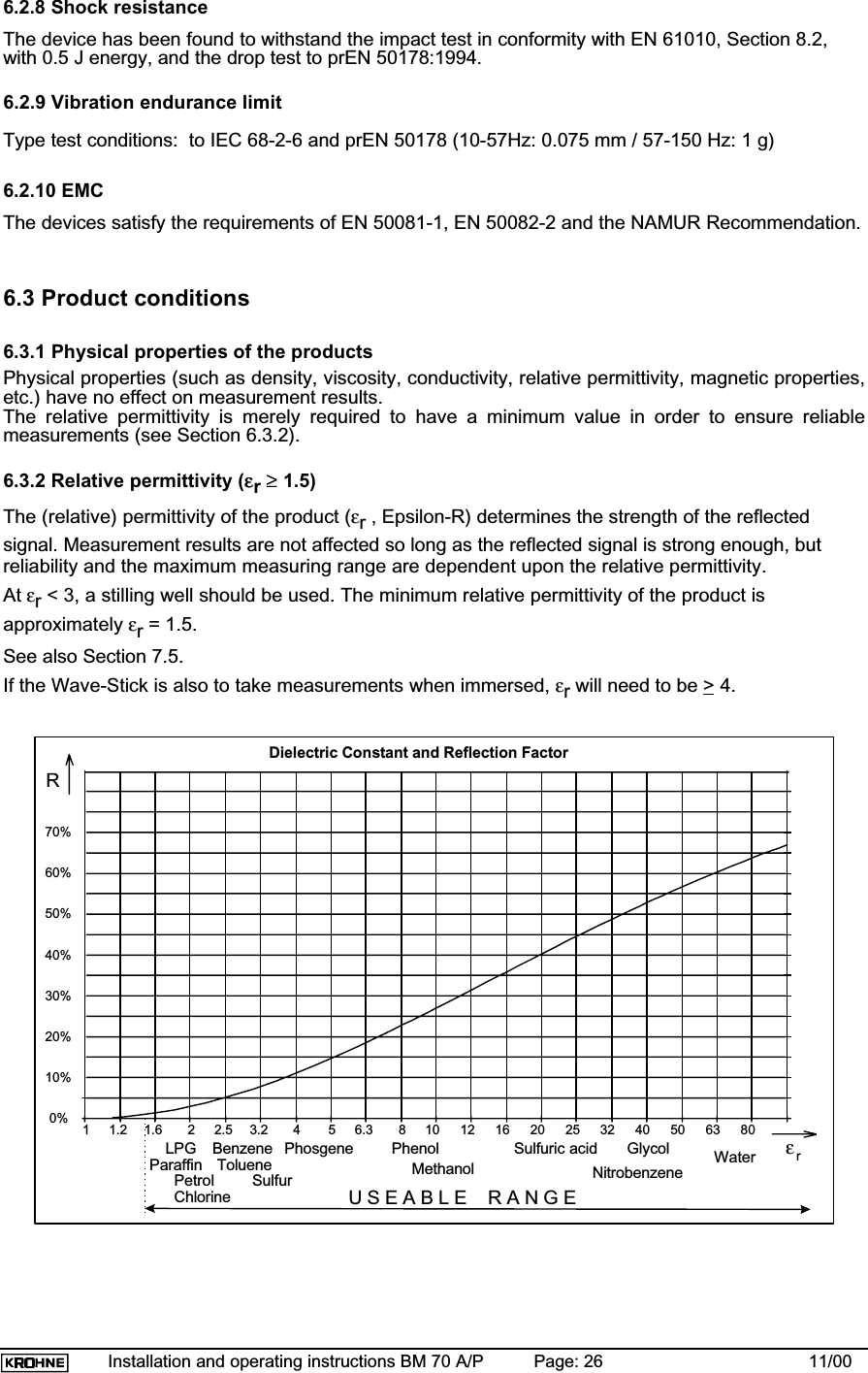
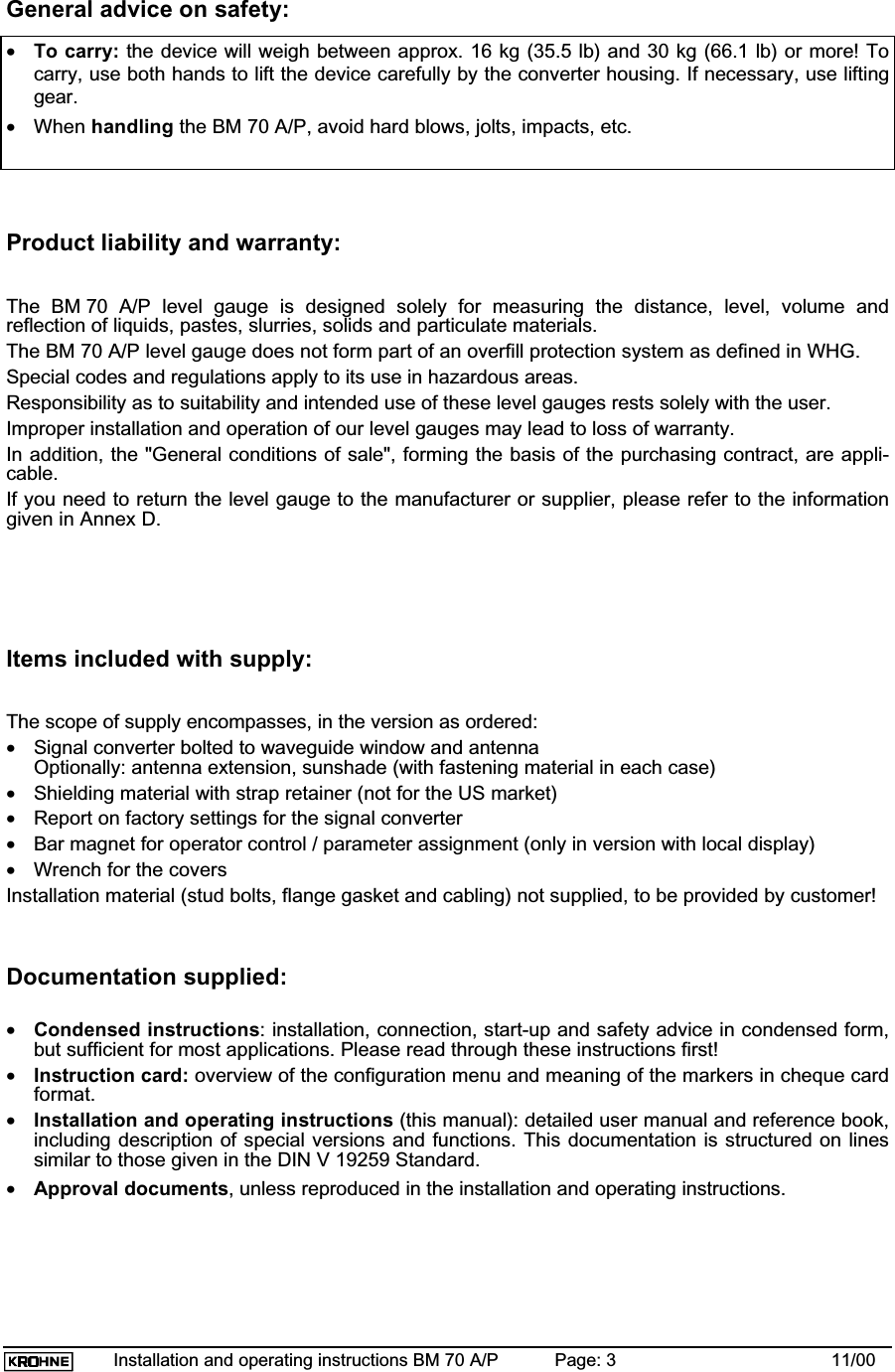
![Installation and operating instructions BM 70 A/P Page: 27 11/006.3.3 Product limitationsRadar-based level measuring devices are not suitable for the following products:•liquid a mmonia (NH3)•liquid hydrogen (H2)•liquid helium (He)6.3.4 Product temperature (unrestricted)The product temperature is not a relevant factor, provided the ambient temperature (see 6.2.2) andthe flange temperature (see 6.2.3) are within the specified limits.6.3.5 maximum allowable operating pressure (max. 64 bar / 928 psig)Flange system with horn antenna or Wave-Guide:PN 16 PN 25 PN 40 PN 64DN 80 16 bar (232 psig) --- 40 bar (580 psig) 64 bar (928 psig)DN 100 16 bar (232 psig) --- 38 bar (551 psig) 55 bar (798 psig)DN 150 16 bar (232 psig) --- 34 bar (493 psig) 47 bar (682 psig)DN 200 16 bar (232 psig) 25 bar (363 psig) 32 bar (464 psig) 45 bar (653 psig)Information on higher pressures (up to 400 bar / 5800 psig) supplied on requestWave-Stick without plate resp. LP flange system: max. 2 bar / 29 psigWave-Stick with plate: max. 16 bar, dependent on temperature:Temperature TPressure-20 +150 °C+100-15+15232 (46 - 0.3·T[°C]) bar-4 +302 °F+212-1+1+16bar psig(740 - 2.4·T[°F]) psig6.4 MaintenanceCleaning the antennaParticular process applications can cause severe contamination of the antenna. Microwaves cannotbe properly emitted or received when reflected from deposits on the antenna. In such cases, theBM 70 A/P will usually indicate maximum level (volume) or minimum distance.The level of contamination at which such errors occur depends firstly on the product concerned, andsecondly on the reflection index, which is mainly determined by the relative permittivity εr.Regular cleaning, or use of the purging device (see Sect. 6.1.7), is advisable if the product has atendency to form deposits, etc.When spraying, washing down, or cleaning with mechanical aids, take special care not to damageeither the horn antenna or the bottom Teflon plug at the waveguide window (see Section 7.4 "Fieldassembly of the BM 70 A/P"). If cleaning agents are used, take material resistance into account!](https://usermanual.wiki/KROHNE/70.Manual/User-Guide-236910-Page-27.png)
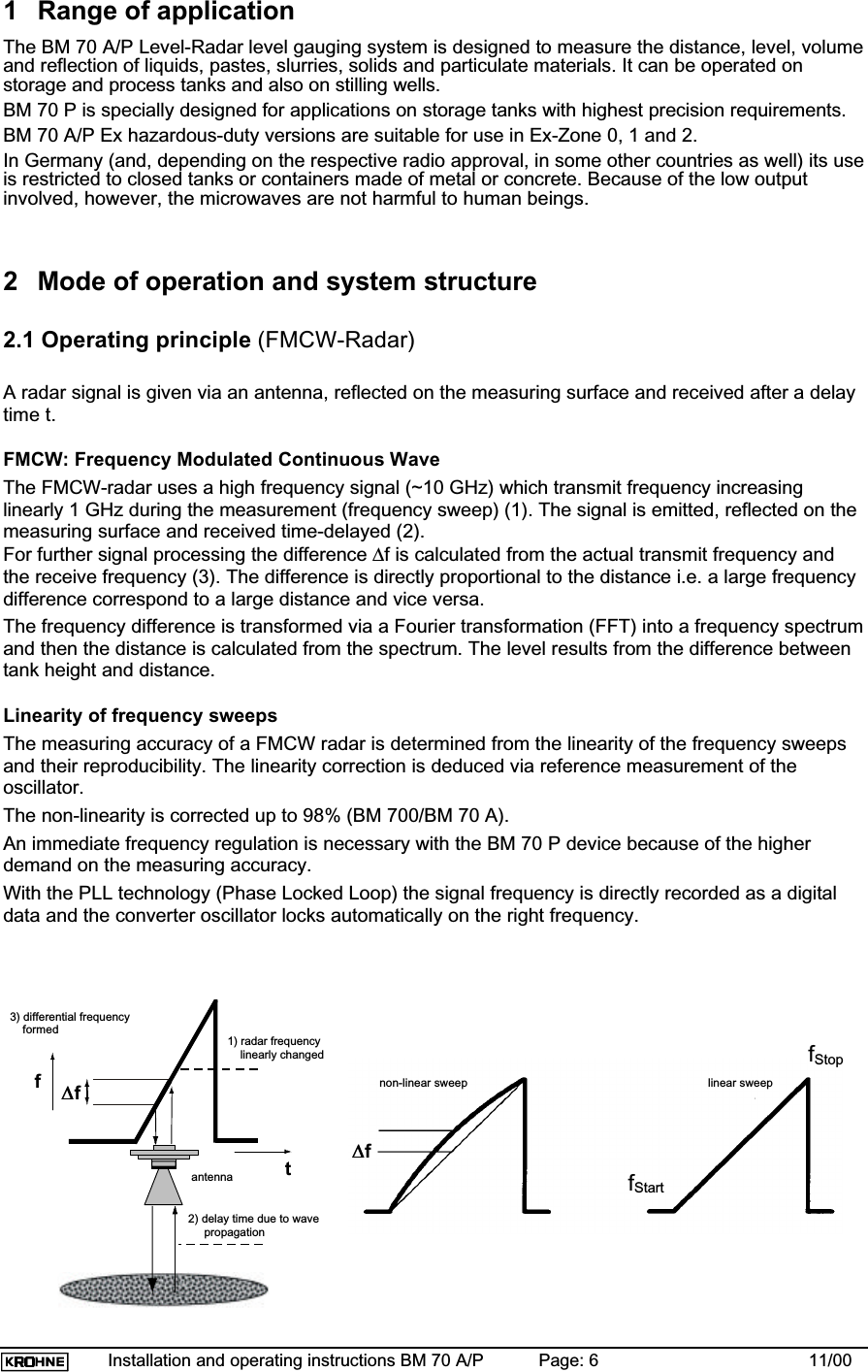
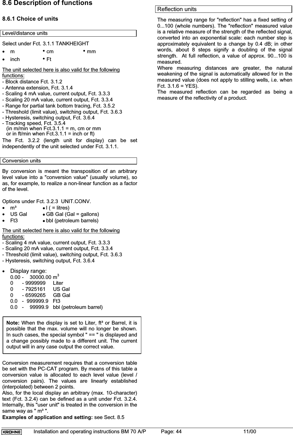
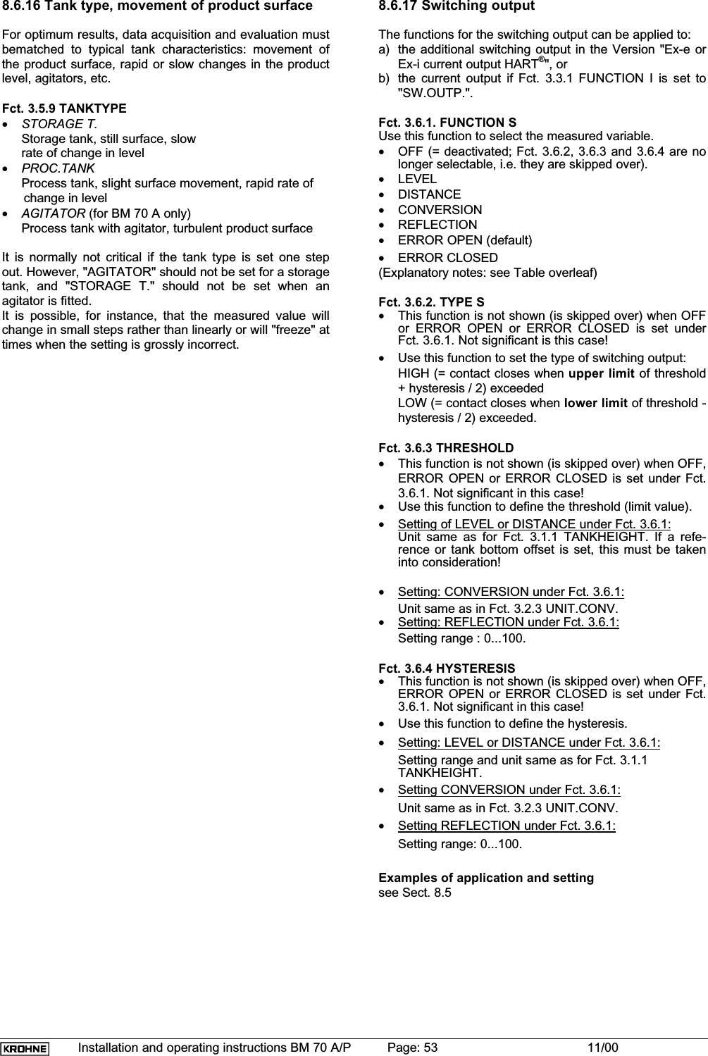
![Installation and operating instructions BM 70 A/P Page: 39 11/008.4 Table of settable functions (Versions 3.00, 3.01, 3.02, 3.03, 4.02, 4.03)Function (Fct.) Enter range Default value Description1.0 OPERATION1.1 DISPLAY1.1.1 FCT.DISP Options LEVELDISTANCECONVERSIONREFLECTIONLEVEL Select function of display(value to be displayed).1.1.2 UNIT.LENGTH Options m cm mminchFtPERCENTBARGRAPHMeter [m] Select unit for value of length to be displayed(level/distance).1.1.3 UNIT. CONV. Options m3lUS GalGB GalFt3bblPERCENTBARGRAPHUSER UNITCubic meter [m3] Select unit for conversion value to be displayed("volume table").2.0 TEST2.1 HARDWARE2.1.1 MASTER Special function Tests the hardware of the master.2.1.2 DISPLAY Special function Tests the hardware of the display.2.1.3 STATUS Options Module DISModule MWDisplays ID-Number and Status Bytes2.2 CUR.OUTP.I2.2.1 VALUE I Value display Displays the actual value of the current output.2.2.2 TEST I Options 2 mA4 mA6 mA8 mA10 mA12 mA14 mA16 mA18 mA20 mA22 mA2 mA Output of selected value to the current output.IMPORTANT !!! With safety inquiry because of directaccess to the current output !!!(Exi = min. 3.6 mA)2.3 SW.OUTPUT2.3.1 TEST S Options OPENCLOSEDOPEN Switching output on/off.IMPORTANT !!! With safety inquiry because of directaccess to the switching output !!!2.4 FIRMWARE2.4.1 MASTER Display Displays the firmware version of the master.2.4.2 DISPLAY Display Displays the firmware version of the display.3.0 INSTALL.3.1 BASIS.PARAM3.1.1 TANKHEIGHT Options, unit m cm mminchFtEnter0.50 [m] ... max. tank heightm10.00 m* / 20.00 m *To input the tank height.The tank height is defined as the vertical distancebetween the bottom edge of the flange and the tankbottom.The unit entered here is also used for all other lengthinputs.3.1.2 BLOCKDIST Enter0.10 [m] ... tank height0.50 m * To input the block distance.The block distance marks the non-measurable rangebelow the bottom edge of the flange.3.1.3 ANTENNA Options STANDARDWAVE STICKSTANDARD * Selection of the antenna type.(WAVE STICK only for BM 70 A)3.1.4 ANT.EXTENS. Enter0.00 [m] ... Tank height0.00 m * To input the length of the antenna extension.3.1.5 DIST.PIECE Enter0 ... 2000 [mm]0 mm * To input the length of the flange distance piece in [mm](high-temperature version = 120 mm).](https://usermanual.wiki/KROHNE/70.Manual/User-Guide-236910-Page-39.png)
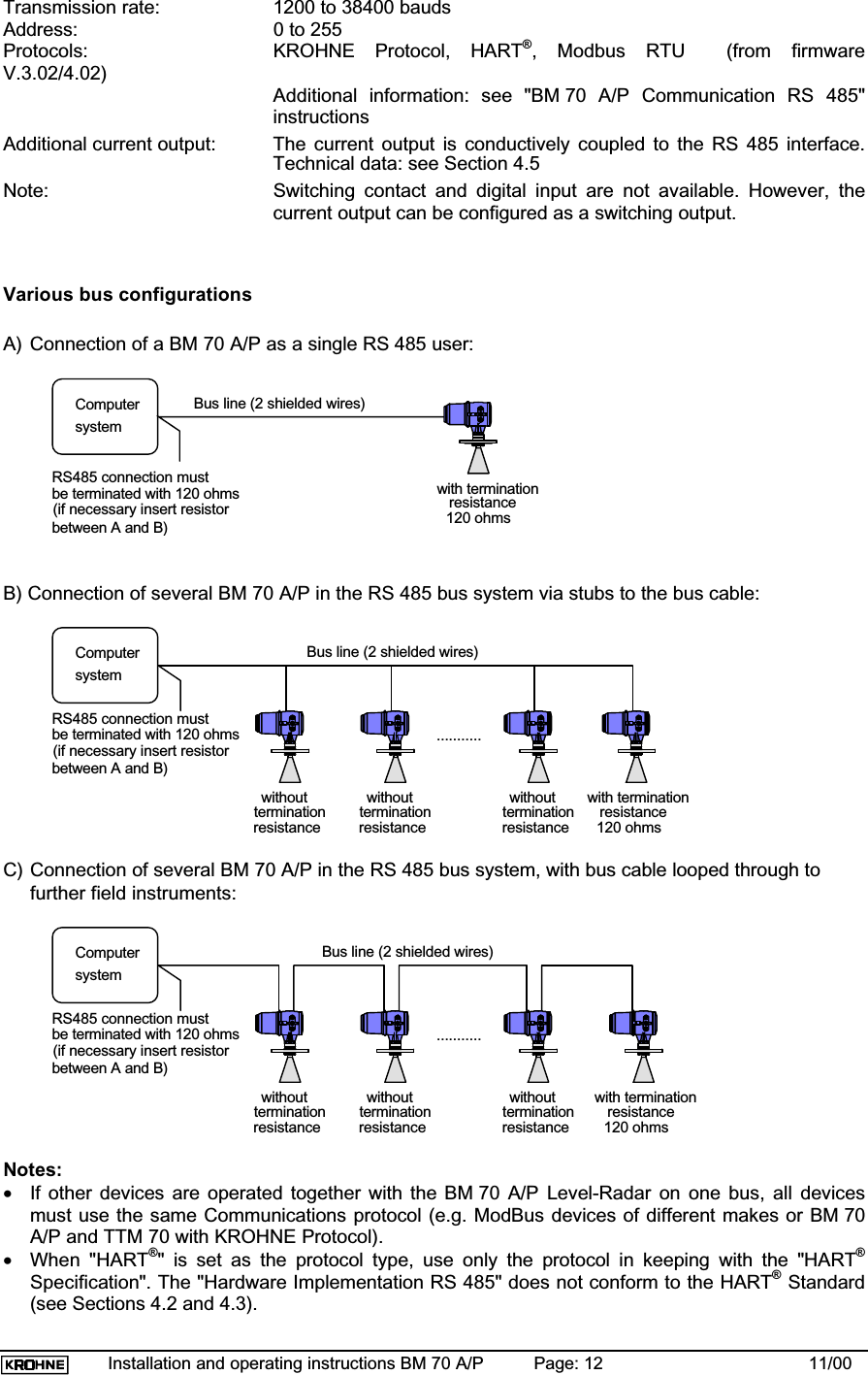
![Installation and operating instructions BM 70 A/P Page: 40 11/00Function (Fct.) Enter range Default value Description3.1.6 STILLWELL Options NOYESIf "YES":Enter (restraint)STILLWELL DIA.25 ... 200 [mm]NO100 mmSelect: with or without stilling well.When "YES" selected, the inside diameter of thestilling well is additionally entered in [mm].3.1.7 REF.OFFSET Enter-10.00 ... + 10.00 [m]0.00 m To input the reference offset(relocation of the upper reference point).3.1.8 TB. OFFSET Enter-100.00 ... + 100.00 [m]0.00 m To input the tank bottom offset(relocation of the lower reference point).3.2 DISPLAY3.2.1 FCT.DISP. Options LEVELDISTANCECONVERSIONREFLECTIONLEVEL Select function of the display(value to be displayed).3.2.2 UNIT.LENGTH Options m cm mminchFtPERCENTBARGRAPHMeter [m] Select unit for length value to be displayed(level/distance).The unit selected here is used only for display of lengthvalues.3.2.3 UNIT.CONV. Options m3lUS GalGB GalFt3bblPERCENTBARGRAPHUSER UNITCubic meter [m3] Select unit for conversion values to be displayed("volume table").The unit selected here is used only for display of theconversion value.3.2.4 USER UNIT Text entry10 ASCII characters__________ Input of freely programmable unit for the conversiontable (max. 10 characters).3.2.5 ERROR MSG. Options NOYESYES Select whether error messages are to be shown in thedisplay.3.3 SIGNAL.OUTP.3.3.1 FUNCTION I Options OFFLEVELDISTANCECONVERSIONREFLECTIONSW.OUTP.LEVEL Select function of the current output(measured value to be displayed, orOFF = current output switched off = constant 4 mA).3.3.2 RANGE I Options 4-20 mA/E224-20 mA/E24-20 mA4-20 mA/E22 Select the range for the current output and erroroutput.3.3.3 SCALE 4 mA Enter-200.00 ... +200.00 [m]0.00 ... 99999.99 [m3]0 ... 100 [Refl.]0.00 m0.00 m30Input the lower range value for output to the currentoutput.(Input is dependent on the selected function of thecurrent output. The values for level and distanceinclude the tank bottom and reference offset, resp.).3.3.4 SCALE 20 mA Enter-200.00 ... +200.00 [m]0.00 ... 99999.99 [m3]0 ... 100 [Refl.]10.00 m *10.00 m3100Input of the full-scale range for output to the currentoutput.(Input is dependent on the selected function of thecurrent output. The values for level and distanceinclude the tank bottom and reference offset, resp.).3.3.5 BAUDRATE Options 1200 Bd.2400 Bd.4800 Bd.9600 Bd.19200 Bd.38400 Bd.19200 Bd. * Select the baud rate for the Communication interface(not relevant to HART via current output).(For Fct. 3.3.7 = PROFIBUS-PA or F.FOUND.:deviating options.)3.3.6 ADDRESS Enter 0 ... 255 0 Input of the device address for Communication.(For Fct. 3.3.7 = PROFIBUS-PA or F.FOUND.:deviating input range)3.3.7 PROTOCOL Options HART®KROHNE/PC(MODBUS)(PROFIBUS-PA)(F.FOUND.)HART®Select the Communications protocol.(only when appropriate hardware provided)](https://usermanual.wiki/KROHNE/70.Manual/User-Guide-236910-Page-40.png)
![Installation and operating instructions BM 70 A/P Page: 41 11/00Function (Fct.) Enter range Default value Description3.4 USER DATA3.4.1 LANGUAGE Options GB/USA,D, F, I, E, P, SGB/USA * Select language to be used in the display(English, German, French, Italian, Spanish, Portu-guese, Swedish)3.4.2 ENTRY CODE 1 Options NOYESNO Switch the access lockout for the configuration menuon/off.3.4.3 CODE 1 Enter code RRREEEUUU Input of the Entry Code.3.4.4 LOCATION Text BM70A-00BM70P-00Input of a max. 8-character device identifier.3.5 APPLICAT.3.5.1 AUTO TANKH. Special function Automatic determination of the tank height.3.5.2 EMPTY.SPEC. Options OFFONRECORDOFF * Switch the empty-tank spectrum (profile of the emptytank) on/off, or make new recording.3.5.3 TIMECONST. Value1 ... 100 [s] (BM 70 A) 10 ... 100 [s] (BM 70 P)10 s (BM 70 A)30 s (BM 70 P)Input of the time constant for measured-value filtering(low-pass).3.5.4 TRACING.VEL. Value0.01 ... 10.00 [m/Min] (BM 70 A)0.01 ... 1.00 [m/Min] (BM 70 P)0.50 m/min(BM 70 A)0.10 m/min(BM 70 P)Input of the maximum rate of change in the level thatcan occur in operation.3.5.5 MULT.REFL. Options NOYESNO Switch the multi-reflection identifier on/off.3.5.6 BD-DETECT. Options NOYESYES Switch the block distance (overfill) detector on/off.3.5.7 FUNCT. FTB Options OFFPARTIALFULLOFF Select function of the tank bottom tracking system.(FULL for BM 70 A only)3.5.8 EPSILON R Enter1.1000 ... 8.00002.0000 Input of the relative permittivity of the product for thetank bottom tracking system.3.5.9 TANKTYPE Options STORAGE TANKPROC.TANK.AGITATORPROC.TANK. Select the tank type.(AGITATOR for BM 70 A only)3.6 SW.OUTP.S.3.6.1 FUNCTION S Options OFFLEVELDISTANCECONVERSIONREFLECTIONERROR OPENERROR CLOSEDERROR OPEN Select the function of the switching output.3.6.2 TYPE S Option HIGHLOWHIGH Select type of limit value for the switching output.(not applicable to Function OFF, ERROR OPEN orERROR CLOSED)3.6.3 THRESHOLD Value-200.00 ... +200.00 [m]0.00 ... 99999.99 [m3]0 ... 100 [Refl.]5.00 m5.00 m350Input of the threshold value for the switching output.(Input is dependent on the function of the switchingoutput. The values for level and distance include thetank bottom and reference offset, resp.)3.6.4 HYSTERESIS Value0.00 [m] ... Tank height0.00 ... 99999.99 [m3]0 ... 100 [Refl.]0.10 m0.10 m310Input of the hysteresis for the switching output.(Input is dependent on the function of the switchingoutput.)*: Default values following a parameter reset (use of a new EEPROM not yet described).The factory setting for the parameters marked with * is dependent upon the device version and customer specifications (if the tank height is known at the time the order is placed).](https://usermanual.wiki/KROHNE/70.Manual/User-Guide-236910-Page-41.png)
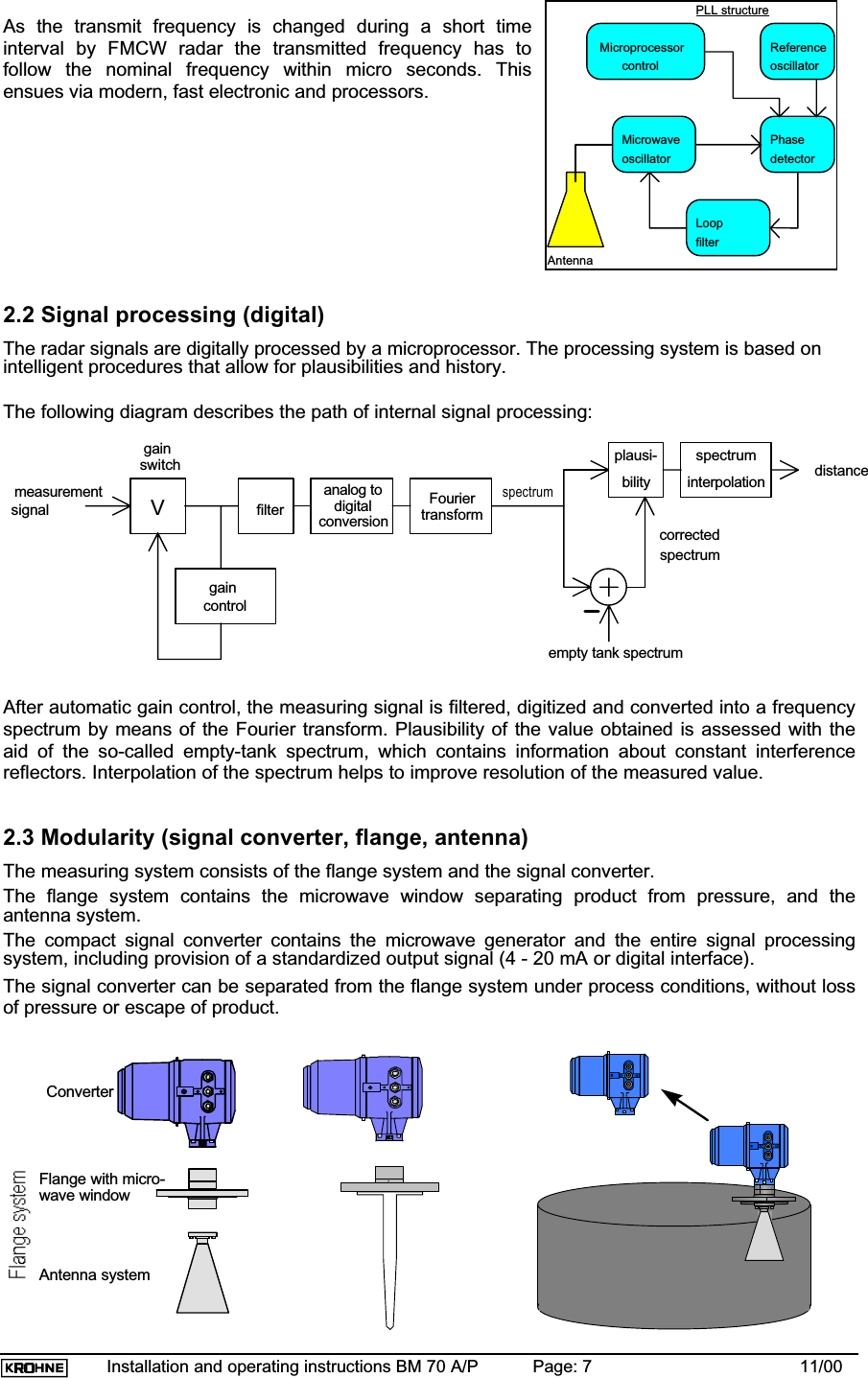
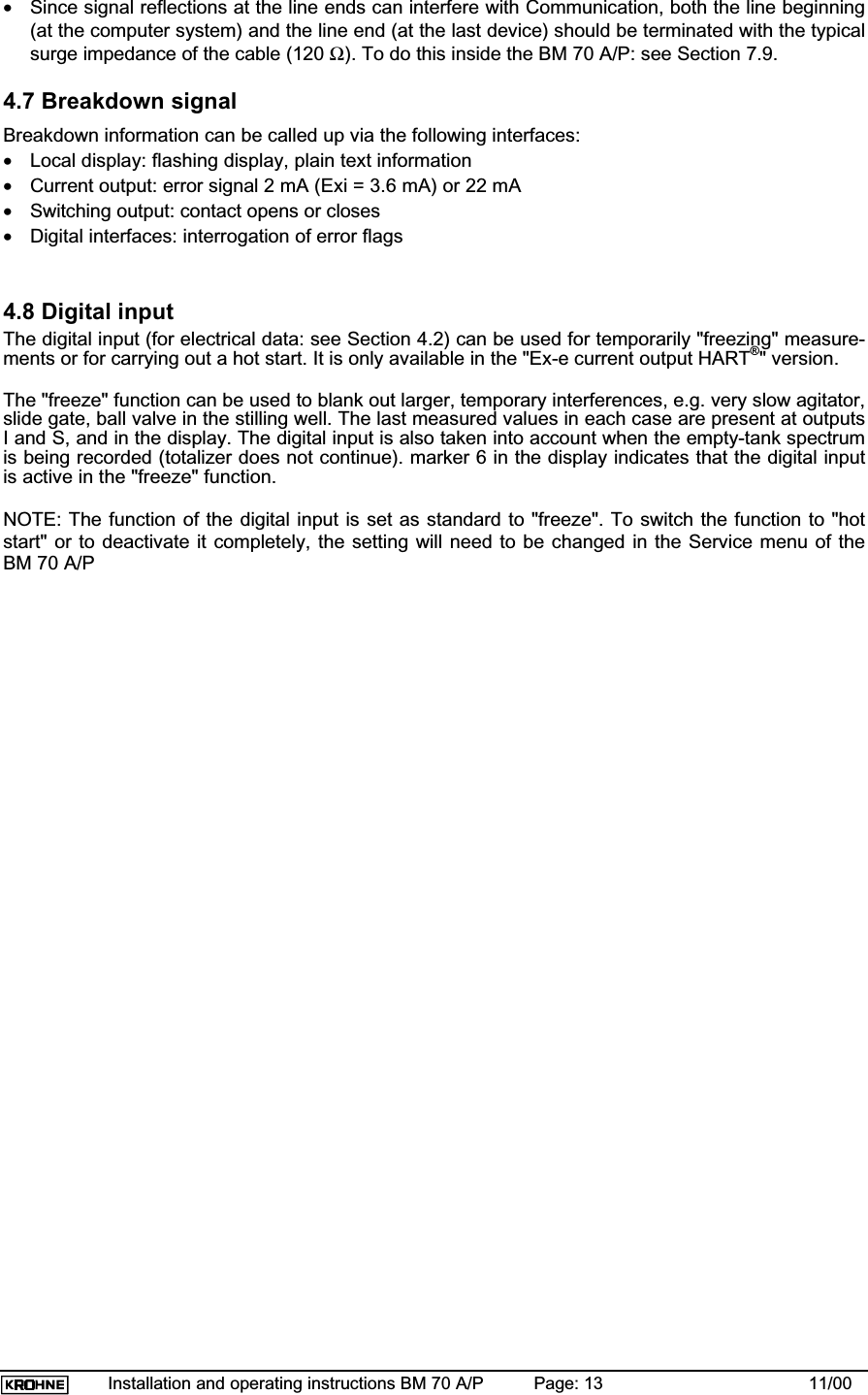
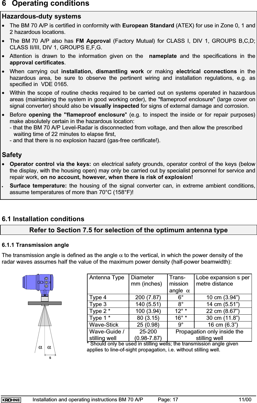
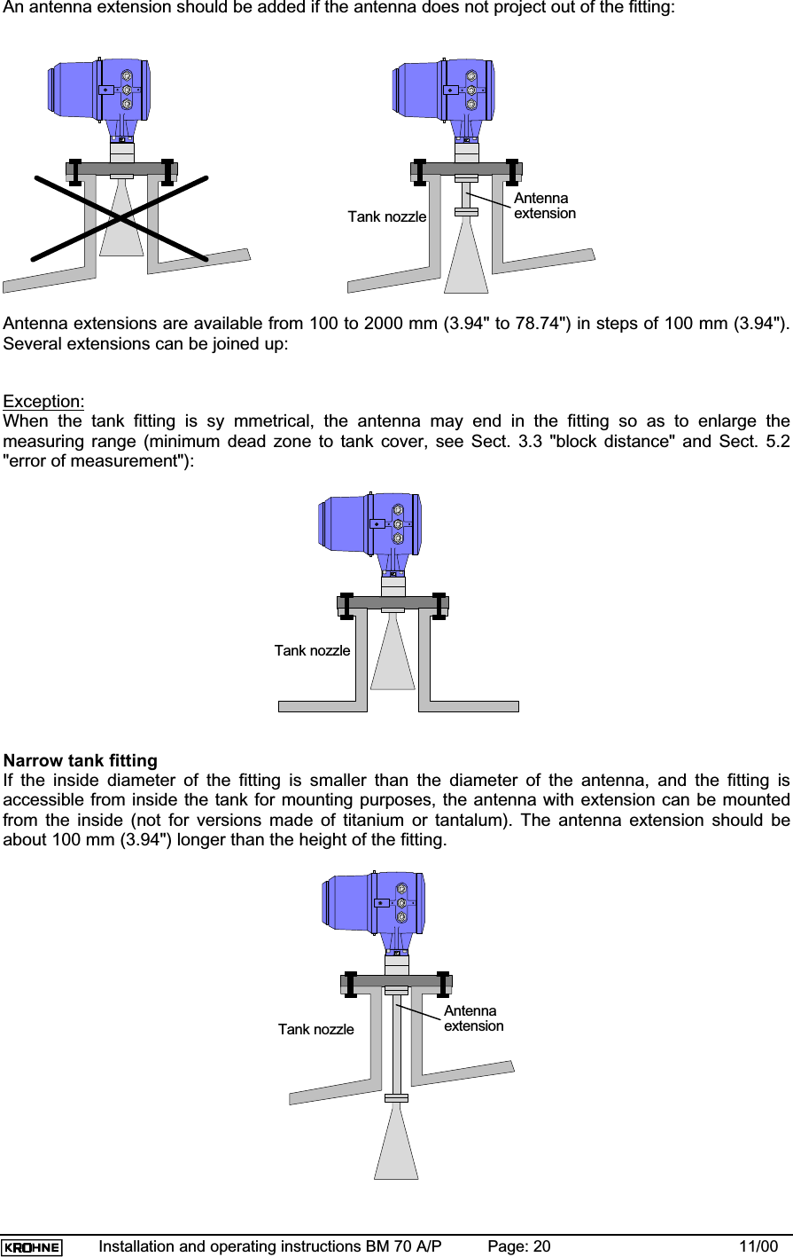
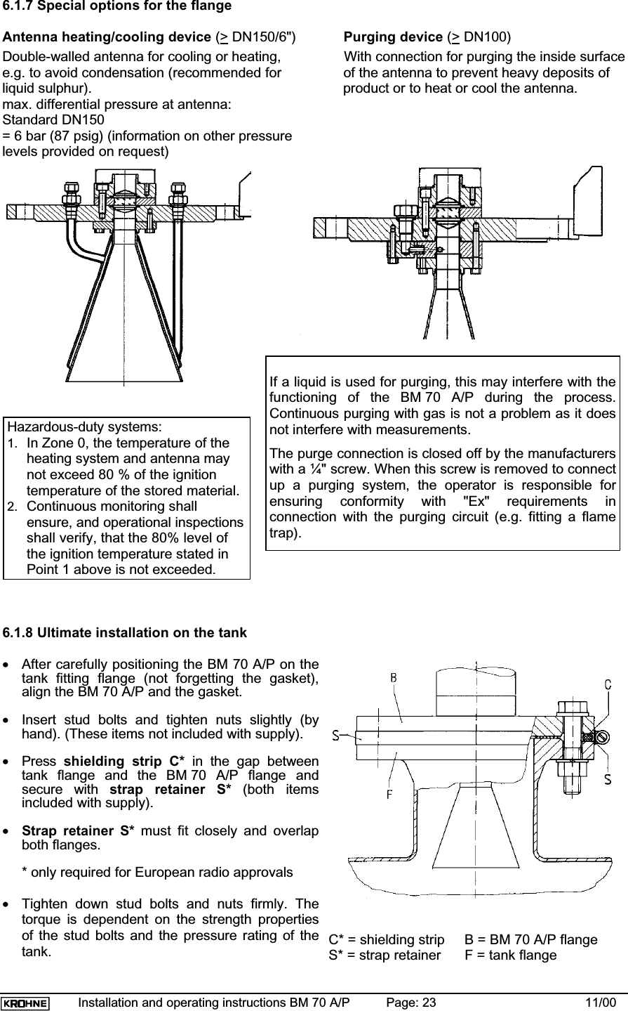
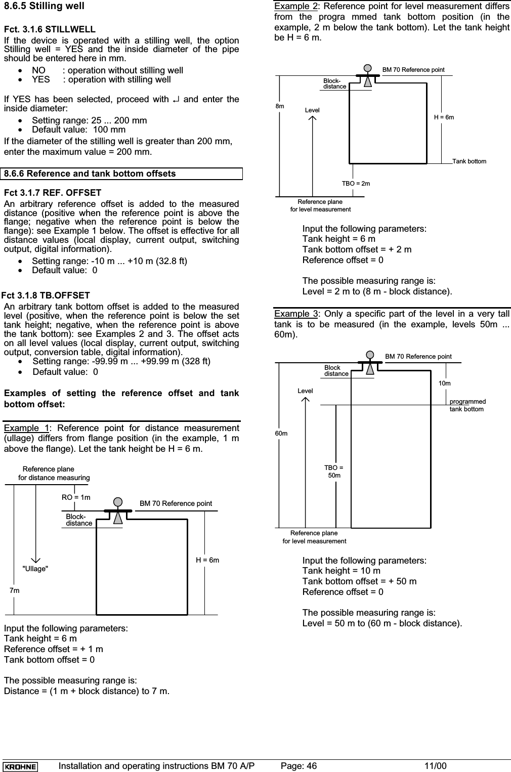
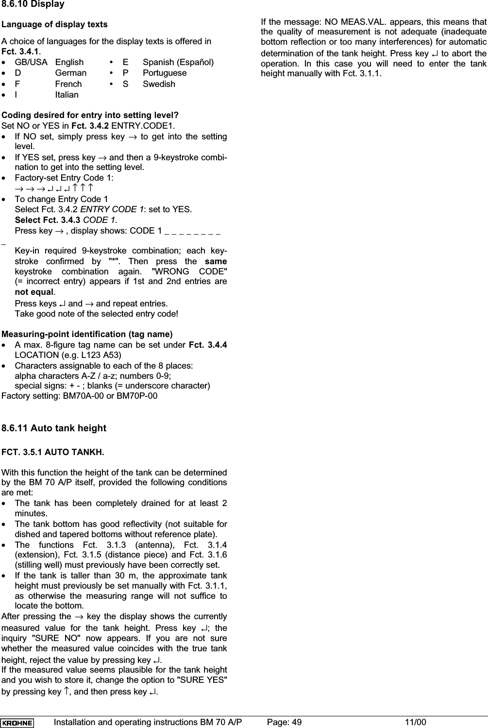
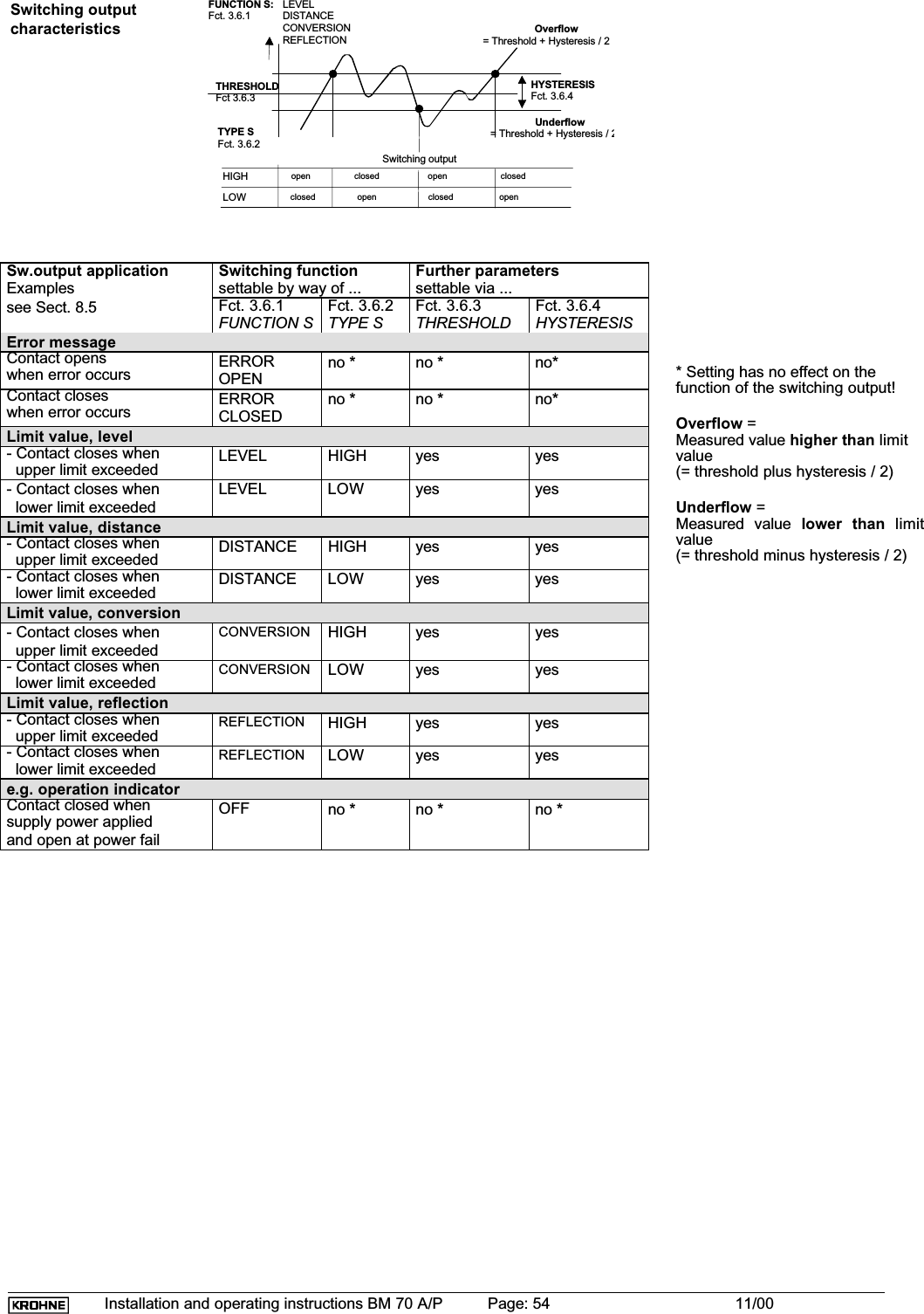
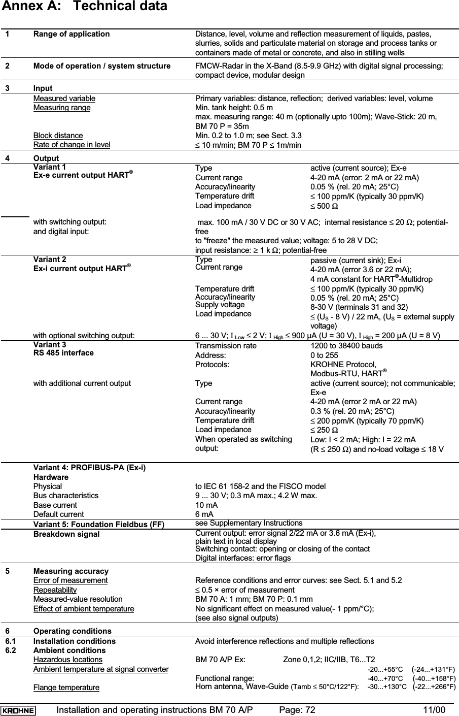
![Installation and operating instructions BM 70 A/P Page: 45 11/00HAVBDO-Ref (+)O-TB (+)DSO-RefO-TBHAVBD- Antenna extensionFct. 3.1.1 [0.00 m ... max. tank height]Fct. 3.1.4 [0.00 m ... Tank height]Fct. 3.1.2 [0.10 m ... Tank height]Fct. 3.1.7 [ -10.00 ... + 10.00 m]Fct. 3.1.8 [ -100.00 ... + 100.00 m]DS Fct. 3.1.5 [0 ... 2000 mm]Bottom edge of flangeProduct surfacedatum plane for distanceLeveltank bottomdistance- tank height- block distance- distance piece- reference offset- tank bottom offsetdatum plane for level8.6.2 Vessel (tank) heightFct. 3.1.1 TANKHEIGHT•Definition of the tank height for the BM 70 A/P:Distance between the top edge of the tank fitting andthe lower reference point.•The lower reference point is that "point" in the vesselon which the microwaves emitted by the BM 70 A/Pimpinge and from which they are reflected. This can bethe tank bottom (sy mmetrical tank with flat bottom) orthe non-horizontal part of the bottom (e.g. tank withdished bottom) or an additionally fitted plate. TheBM 70 A/P cannot measure below the lower referencepoint (usually a "sump" is left in the tank, see diagramin Sect. 8.5).•Selection of unit, see Sect. 8.6.1.•Setting ranges for the tank height BM 70 A (standard):• 00.50 - 40.00 m• 0050 - 4000 cm• 00500 - 40000 mm• 0019.7 - 1574.74 inch• 001.64 - 131.22 ftFor BM 70 P: max. 35m / 1377.9 inch / 114.8 ft•Depending on the version, it is also possible to set anupper limit for the tank height (e.g. Wave-Stick: 20 m).The maximum value can be increased by KROHNEService to up to 100 m. (For BM 70 A only)•The tank height set at this point is simultaneously theupper limit of the setting ranges for the followingfunctions:- Block distance, Fct. 3.1.2- Antenna extension, Fct. 3.1.4- Hysteresis, switching output, Fct. 3.6.4•If the tank height is changed to a value greater than 30m, a new empty spectrum must subsequently berecorded, see Sect. 8.6.12. (not applicable to BM 70P).8.6.3 Block distance, antenna type and antennaextensionFct. 3.1.2 BLOCKDIST•Caked deposits or contamination of the antenna, forexample, can cause faulty measurements directlybelow the antenna. The function "block distance" isused to specify a zone below the flange in whichmeasurements are not to be carried out.•Signals within the block distance are suppressed; arise in the level above this limit will result in ameasurement corresponding to a distance = blockdistance, when Fct. 3.5.6 BD-DETECT = ON.•Unit and setting range: same as Fct. 3.1.1TANKHEIGHT.•Recommended minimum value (see also Sect. 3.3): - for "Wave-Stick": 200 mm - for stilling wells and "Wave-Stick SW": antenna length + 300 mm - all other versions in storage tanks: antenna extension + antenna length + 100 mm - all other versions in process tanks: antenna extension + antenna length + 200 mmFct. 3.1.3 ANTENNA•The antenna type is factory-set here.•STANDARD (all versions incl. "Wave-Stick SW" butexcl. "Wave-Stick")•WAVESTICK (not for "Wave-Stick SW")•BM 70 P: only STANDARD setting possible.Fct. 3.1.4 ANT.EXTENS.The length of the supplied antenna extension is factory-sethere.•Unit and setting range: same as Fct. 3.1.1TANKHEIGHT.This setting may only be changed when a longer or shorterantenna extension is installed. Otherwise faulty measure-ments may result because the BM 70 A/P allows for thislength when measuring. After changing any antennaextension, record a new empty spectrum, see Sect. 8.6.12.When a curved antenna extension is used, only thevertical component (vertical offset) should be enteredhere.Example (S-shaped extension): Fct. 3.1.4 = 323 mm.323 mm300 mm(Fct. 3.1.4)(Fct. 3.1.5)8.6.4 Distance pieceFct. 3.1.5 DIST.PIECEThe length of any supplied distance piece above themounting flange is factory-set here.•Setting range: 0 ... 2000 mm•Default value: 0 mmThe value of 120 mm should be entered for the high-temperature version of the flange system.When a curved antenna extension is used, the horizontalcomponent of this extension should additionally be entered(= geometric length of the pipe minus the vertical offset).Example (see drawing above): Fct. 3.1.5 = 300 mm.](https://usermanual.wiki/KROHNE/70.Manual/User-Guide-236910-Page-45.png)
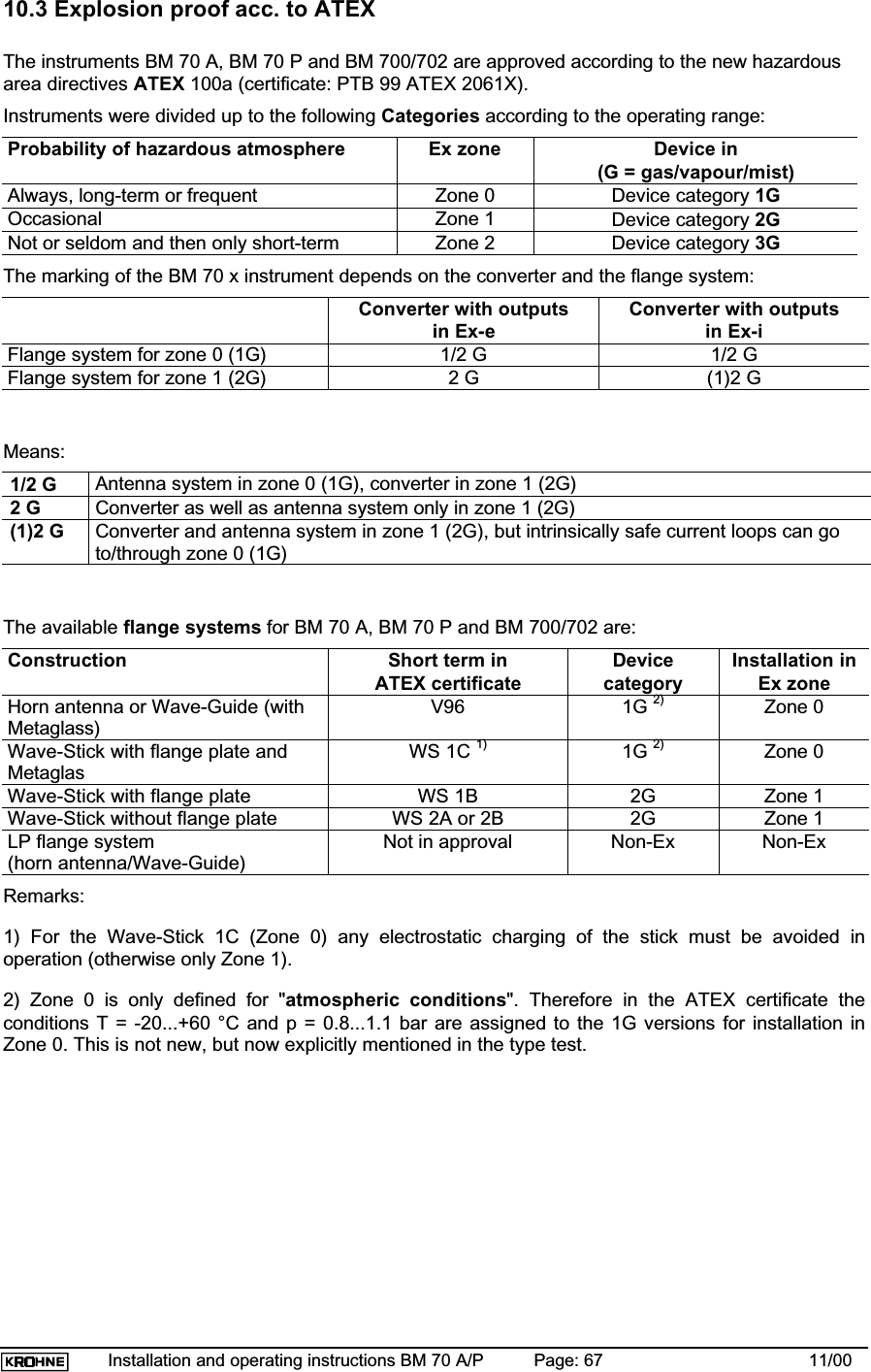
![Installation and operating instructions BM 70 A/P Page: 66 11/0010 Certificates and approvals10.1 Hazardous-duty approvalsCountry Authority Certificate No. Class Device typeGermany/Europe PTB PTB99 ATEX 2061X EEx de IIC T6..T1 (Z.0) BM 70EEx de [ia]/[ib] IIC/IIB T6..T3 (Z.0) BM 70 iUSA FM J.I.3000813 I Div.1 Gr.B/C/D BM 70II/III Div.1 Gr.E/F/G BM 70I/II/III Div.2 Gr. B/C/D/F/GUSA FM J.I.3006165 I Div.1 Gr.B/C/D BM 70.iII/III Div.1 Gr.E/F/G BM 70.iI Div.2 Gr. A/B/C/DII/III Div.2 Gr. P/GCanada CSA in preparation BM 70.Japan RIIS in preparation BM 70.The texts of valid "Ex" certificates of conformity and type approvals are reprinted in theattached "Ex" documentation.10.2 Other approvals and certificatesType Company Date/Certificate No. Radio approval BZT Vfg1117/1989; Vfg241/1995Radio Licence FCC JH5BM70Preliminary approval to German pressurevessel code DruckbehV/TRB511 (flange V 96) RWTÜV No. 5636602](https://usermanual.wiki/KROHNE/70.Manual/User-Guide-236910-Page-66.png)
![Installation and operating instructions BM 70 A/P Page: 70 11/0011 Order informationTechnical information relevant to the orderBM 70 A/P Level-Radar♦Connecting flange: ................... ________________________________________________♦Flange and antenna material:... ________________________________________________♦Waveguide seal: ...................... Viton FFKM Kalrez2035 Other _____________♦Antenna type:...........................Type 4 (200 mm) Type 3 (140 mm)................................................Type 1 (74 mm) Type 2 (100 mm) [for stilling well dia.:_]................................................Wave-Stick Wave-Guide (length: _______________ )♦Antenna extension:................... ________________________________________________♦Power supply:........................... 24V DCAC 200-240V AC 100-120V AC♦Signal output:...........................Current output: active (Ex-e) Ex-i passivealternatively: .................Digital: RS 485 Bus: __________________________♦Explosion protection.................none Zone 0 Zone 1Special itemsAdditional calibration (BM 70 A Precision) High-precision version (BM 70 P)90° Antenna extension .............S-shaped antenna extensionPurge connection .....................Antenna heatingOthers: ____________________________________________](https://usermanual.wiki/KROHNE/70.Manual/User-Guide-236910-Page-70.png)
![Installation and operating instructions BM 70 A/P Page: 71 11/0012 External standards, codes and directivesDIN V 19259: 1996-10. Documentation of devices, Data types with classsification scheme for measuringequipment with analog or digital output for industrial process measurement [in German]VDI/VDE 3519 (part 2): 1994-12. Level measurement of liquids and solids (bulk solids) [in German]DIN VDE 0165: 1991-02. Installation of electrical apparatus in hazardous areas [in German]DIN EN 50014: 2000-02. Electrical apparatus for potentially explosive atmospheres, General requirementsDIN EN 50018: 1995-03. Electrical apparatus for potentially explosive atmospheres, Flameproof enclosure "d"DIN EN 50019: 1996-03. Electrical apparatus for potentially explosive atmospheres, Increased safety "e"DIN EN 50020: 1996-04. Electrical apparatus for potentially explosive atmospheres, Intrinsic safety "i"DIN EN 50284: 2000-02. Special requirements for construction, test and marking of electrical apparatus ofequipment group II, category 1 GDIN EN 50081-1 (VDE 0839 part 81-1): 1993-03. Electromagnetic compatibility (EMC), Generic emissionstandard, Part 1: Residential, commercial and light industryEN 50082-2: 1995-03. Electromagnetic compatibility, Generic immunity standard, Part 2: Industrial environmentNE 21 NAMUR recommendation „Electromagnetic compatibility (EMC) of industrial process and laboratorycontrol equipment“, 1998-08DIN EN 61010-1 (VDE 0411 part 1):1993-04. Safety requirements for electrical equipment for measurement,control and laboratory use, general requirementspr EN 50178 / DIN EN 50178: 1994-08: Electronic equipment for use in power installationsDirective 89/336/EWG (CE marking)DIN EN 60068-2 (IEC 68-2): 1995-03. Environmental testsDIN IEC 68-2-6: 1990-06. Electrical engineering, Basic environmental test proceduresDIN EN 60654, part 1 (IEC 654-1): 1994-02: Industrial process measurement and control equipment; Operatingconditions; Climatic ConditionsDIN EN 60529: 2000-09: Degrees of protection by enclosures (IP Code)DIN 2501: 1972-02: Flanges - Fitting dimensions [in German]DIN 2527: 1972-04: Blind flanges [in German]ANSI B 16.5: 1988: Pipe Flanges and Flanged FittingsDIN 11851: 1998-11: Fittings for food, chemical and pharmaceutical industry - Stainless steel screwed pipeconnections - Design for rolling in and welding-onDIN EN 10088, Teil 1: 1995-08: Stainless steels - Catalogue of the stainless steelsDIN 55990: 1979-12: Verification of paints and similar coating materials; Powder mould coatings .... [inGerman]HUG-3: HART FSK Physical Layer Specification Rev. 7.2: 1993-0513 Quality assuranceKROHNE Messtechnik GmbH & Co. KG is certified to:•DIN ISO 9001 / EN 29001 and•KTA 1401 QSP 4A (nuclear power engineering)](https://usermanual.wiki/KROHNE/70.Manual/User-Guide-236910-Page-71.png)
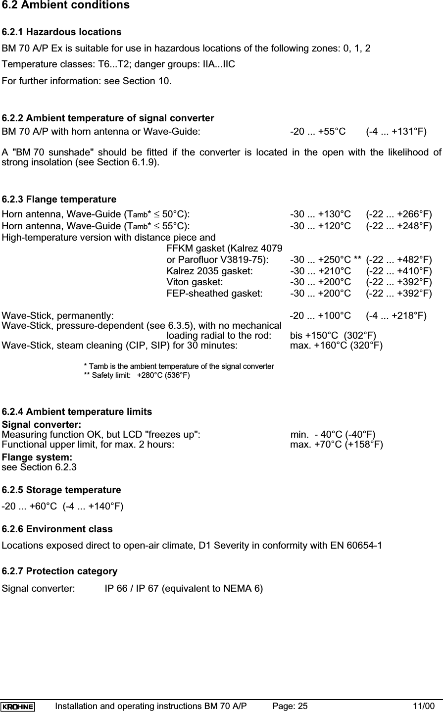
![Installation and operating instructions BM 70 A/P Page: 73 11/00Wave-Stick:Horn antenna, Wave-Guide (Tamb ≤ 55°C/131°F): -30...+120°C(-22...+248°F)High-temperature version with:- FFKM gasket (Kalrez 4079/Parofluor V8545-75): -30...+250°C(-22...+482°F) (safety limit 280°C/536°F)- Kalrez 2035 gasket: -30...+210°C(-22...+410°F)- Viton gasket: -30...+200°C(-22...+392°F)- FEP-sheathed gasket: -30...+200°C(-22...+392°F)-20...+100°C (-4...+212°F)pressure-dependent up to +150°C/302°FEnvironment class Locations exposed direct to open-air climate, D1 Severity in conformity withEN 60654-1Protection category (signal converter) IP 66 / IP 67Shock resistance Impact test to EN 61010, Sect. 8.2 with 0.5 J energy; drop test toprEN 50178Vibration endurance limit IEC 68-2-6 and prEN 50178 (10-57Hz:0.075 mm/57-150 Hz:1 g)EMC EN 50081-1, EN 50082-2; NAMUR Recommendation6.3 Product conditionsPhysical propertiesRelative permittivityNo effect on measurement results; to ensure reliable measurements, therelative permittivity should have the following minimum values:εr> 1.5; εr < 3: stilling well recommended; Wave-Stick immersed: εr> 4Limitations Liquid a mmonia (NH3); liquid hydrogen (H2); liquid helium (He)Temperature of product unrestricted (but be aware of ambient and flange temperatures)Operating pressureHorn antenna/Wave-GuideWave-Stickdependent on flange size and pressure rating (see Table)Standard: max. 64 bar (higher on request)Temperature TPressure-20 +150 °C+100-15+15232 (46 - 0.3·T[°C]) bar-4 +302 °F+212-1+1+16bar psig(740 - 2.4·T[°F]) psig7Component partsDimensions and weights see Sect. 7.2MaterialsHousing: signal converterFlange system, antenna, extensionGasketsWave-StickAluminium with electrostatic powder coating; sight window: glassStainless steel 1.4571 or 1.4435, Hastelloy C4 or B2, titanium, tantalum;(other materials on request)FFKM (Kalrez 4079 or Parofluor V8545-75); Kalrez 2035; Viton (FPM); FEP-sheathed (basically, all versions include PTFE as the material in contact withthe product)only PTFE in contact with product; flange made of 1.4571 (316 Ti)Process connectionHorn antenna/Wave-GuideWave-StickDairy screw connectionTri-Clamp connectionDIN 2501 / DIN 2526, Form C DN 50 … DN 200 / PN 6 … PN 64;ANSI B 16.5 2‘‘ … 8‘‘, Class 150/300 lb/RF;DIN 2501 / DIN 2526, Form C DN 50 … 150;ANSI B 16.5 2‘‘ … 6‘‘;DIN 11 851 DN 50, DN 65, DN 80SMS 1145 51 mm, 63 mm, 76 mmISO 2852 2‘‘ … 4‘‘Electrical connection Cable entries: 3x M25×1,5Terminals: 0.5-2.5 mm² (solid conductor: max. 4 mm²)PE or FE and PA: U-clamp terminal (max. 4 mm²)Shielding for RS 485 cable and for current output cable > 100 m8User interfaceKeypad 3 keysMagnetic sensors operation with magnetic pin without opening the housingLocal display 2-line illuminated LCD + 6 status markersUser language German, English, French, Italian, Spanish, Portuguese, SwedishUnits of measurement Length: m, cm, mm, inch, ft, %Volume: m³, Liter, US Gal, GB Gal, ft3, bbl, %Conversion unit: any text9Power supply24 V DCAC 18-31.2 V DC or 18-26.4 V AC (45-66 Hz)115/230 V AC optionally: 100-120 V AC (tolerance: 85-127V),200-240 V AC (tolerance: 170-254V); 45-66 HzPower consumption Typically 7.5 - 10 W / 12 VA](https://usermanual.wiki/KROHNE/70.Manual/User-Guide-236910-Page-73.png)