KROHNE FMCW10G52 Tank Level Probing Radar User Manual HB OPTIWAVE5200 en 120321 4001904901 R01
KROHNE Tank Level Probing Radar HB OPTIWAVE5200 en 120321 4001904901 R01
KROHNE >
Contents
- 1. User Manual
- 2. User Manual EN - JH5FMCW10G52.pdf
User Manual
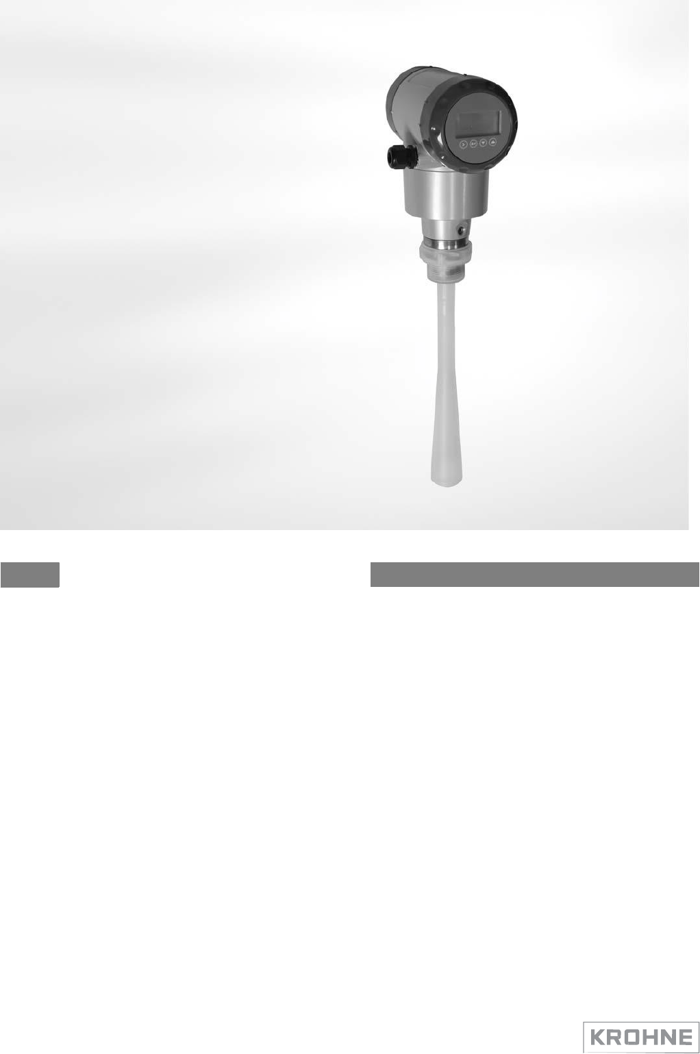
OPTIWAVE 5200 C/F Handbook
Non-contact Radar (FMCW) Level Meter
for distance, level and volume measurement of liquids, pastes and slurries
© KROHNE 03/2012 - 4001904901 - HB OPTIWAVE 5200 R01 en

2
www.krohne.com
03/2012 - 4001904901 - HB OPTIWAVE 5200 R01 en
::
:
IMPRINT :::::::::::::::::::::::::::::::::::::
All rights reserved. It is prohibited to reproduce this documentation, or any part thereof, without the prior written authorisation of
KROHNE Messtechnik GmbH.
Subject to change without notice.
Copyright 2012 by
KROHNE Messtechnik GmbH - Ludwig-Krohne-Str. 5 - 47058 Duisburg (Germany)

03/2012 - 4001904901 - HB OPTIWAVE 5200 R01 en
www.krohne.com
3
OPTIWAVE 5200 C/F CONTENTS
1 Safety instructions 6
1.1 Software history
...............................................................................................................
6
1.2 Intended use
.....................................................................................................................
6
1.3
Certification ......................................................................................................................
6
1.4 Radio
approvals ................................................................................................................
7
1.4.1 European Union
(EU)...............................................................................................................
7
1.4.2 U.S.A. and
Canada...................................................................................................................
8
1.5 Safety instructions from the
manufacturer
.....................................................................
8
1.5.1 Copyright and data protection
................................................................................................
8
1.5.2
Disclaimer
...............................................................................................................................
9
1.5.3 Product liability and warranty
..............................................................................................
10
1.5.4 Information concerning the
documentation.........................................................................
10
1.5.5 Warnings and symbols
used
.................................................................................................
11
1.6 Safety instructions for the
operator
...............................................................................
11
2 Device description 12
2.1 Scope of
delivery.............................................................................................................
12
2.2 Device
description ..........................................................................................................
13
2.3 Nameplates
....................................................................................................................
15
2.3.1 Nameplate
(examples)
..........................................................................................................
15
3 Installation 16
3.1 Notes on installation
......................................................................................................
16
3.2 Storage
...........................................................................................................................
16
3.3
Transport ........................................................................................................................
17
3.4 Pre-installation
requirements .......................................................................................
17
3.5
Installation
......................................................................................................................
18
3.5.1 Pressure and temperature
ranges
.......................................................................................
18
3.5.2 Mounting position (theoretical data for nozzle
position)......................................................
20
3.5.3 Mounting
restrictions............................................................................................................
23
3.5.4 Standpipes (stilling wells and bypass
chambers) ................................................................
27
3.5.5 How to turn or remove the signal
converter ........................................................................
31
3.5.6 How to open the weather protection
....................................................................................
32
4 Electrical connections 33
4.1 Safety
instructions..........................................................................................................
33
4.2 Electrical installation: compact version
........................................................................
33
4.2.1 Non-Ex devices
.....................................................................................................................
35
4.2.2 Devices for hazardous
locations
...........................................................................................
35
4.2.3 PROFIBUS
PA
........................................................................................................................
35
4.2.4 FOUNDATION
Fieldbus .........................................................................................................
35

4
www.krohne.com
03/2012 - 4001904901 - HB OPTIWAVE 5200 R01 en
CONTENTS
OPTIWAVE 5200 C/F
4.3 Remote device version
...................................................................................................
36
4.3.1 General
notes
........................................................................................................................
36
4.3.2 Electrical installation: remote
version
.................................................................................
36
4.3.3 Requirements for communication cables supplied by the
customer..................................
36
4.3.4 How to prepare a communication cable supplied by the customer
....................................
38
4.3.5 How to connect the communication cable to the
device
......................................................
39
4.4 Protection
category ........................................................................................................
43
4.5 Networks
........................................................................................................................
44
4.5.1 General
information
..............................................................................................................
44
4.5.2 Point-to-point
connection
.....................................................................................................
44
4.5.3 Multi-drop
networks .............................................................................................................
45
4.5.4 Fieldbus
networks.................................................................................................................
46
5 Start-up 48
5.1 How to start the
device
...................................................................................................
48
5.1.1 Start-up checklist
.................................................................................................................
48
5.1.2 How to start the device
.........................................................................................................
48
5.2 Operating concept
..........................................................................................................
48
5.3 Digital display
screen .....................................................................................................
49
5.3.1 Local display screen layout
..................................................................................................
49
5.3.2 Keypad buttons
.....................................................................................................................
50
5.4 Remote communication with
PACTware™ ....................................................................
50
5.5 Remote communication with the AMS™ Device
Manager.............................................
51
6 Operation 52
6.1 User modes
....................................................................................................................
52
6.2 Normal
mode..................................................................................................................
52
6.3 Configuration
mode
........................................................................................................
53
6.3.1 General
notes
........................................................................................................................
53
6.3.2 How to get access to the commissioning
menu
...................................................................
54
6.3.3 Keypad
functions...................................................................................................................
55
6.3.4 Menu overview
......................................................................................................................
58
6.3.5 Function
description .............................................................................................................
58
6.4 Further information on device
configuration
.................................................................
65
6.4.1 Protection of the device settings
..........................................................................................
65
6.4.2 Network
configuration ..........................................................................................................
66
6.4.3 Distance measurement
........................................................................................................
67
6.4.4 Level
measurement
..............................................................................................................
68
6.4.5 How to configure the device to measure volume or
mass...................................................
68
6.4.6 How to make a filter to remove radar signal interference
..................................................
69
6.5 Status and error
messages
............................................................................................
71
6.5.1 Device status
(markers)........................................................................................................
71
6.5.2 Device status (NE 107
symbols)............................................................................................
72
6.5.3 Error
handling
.......................................................................................................................
73
7 Service 76
7.1 Periodic
maintenance.....................................................................................................
76
7.2 Service
warranty.............................................................................................................
76

OPTIWAVE 5200 C/F CONTENTS
03/2012 - 4001904901 - HB OPTIWAVE 5200 R01 en
www.krohne.com
5
7.3 Spare parts
availability
...................................................................................................
76
7.4 Availability of
services ....................................................................................................
76
7.5 Returning the device to the
manufacturer.....................................................................
77
7.5.1 General
information
..............................................................................................................
77
7.5.2 Form (for copying) to accompany a returned
device............................................................
78
7.6
Disposal ..........................................................................................................................
78
8 Technical data 79
8.1 Measuring
principle........................................................................................................
79
8.2 Technical
data.................................................................................................................
81
8.3 Minimum power supply voltage
.....................................................................................
86
8.4 Pressure
ratings.............................................................................................................
87
8.5 Antenna
selection
...........................................................................................................
89
8.6 Dimensions and
Weight..................................................................................................
90
9 Description of HART interface 99
9.1 General
description
........................................................................................................
99
9.2 Software history
.............................................................................................................
99
9.3 Connection
variants......................................................................................................
100
9.3.1 Point-to-Point connection - analogue / digital
mode.........................................................
100
9.3.2 Multi-Drop connection (2-wire connection)
.......................................................................
100
9.4 HART® device variables
...............................................................................................
101
9.5 Field Communicator 375 (FC
375)................................................................................
101
9.5.1 Installation
..........................................................................................................................
101
9.5.2
Operation
.............................................................................................................................
102
9.6 Asset Management Solutions
(AMS)
............................................................................
102
9.6.1 Installation
..........................................................................................................................
102
9.6.2
Operation
.............................................................................................................................
102
9.6.3 Parameter for the basic
configuration ...............................................................................
102
9.7 Field Device Tool / Device Type Manager (FDT /
DTM)
................................................
102
9.7.1 Installation
..........................................................................................................................
103
9.7.2
Operation
.............................................................................................................................
103
9.8 HART® menu tree for Basic-DD
..................................................................................
103
9.8.1 Overview Basic-DD menu tree (positions in menu
tree)
....................................................
103
9.8.2 Basic-DD menu tree (details for
settings)..........................................................................
104
9.9 HART® menu tree for AMS
..........................................................................................
104
9.9.1 Overview AMS menu tree (positions in menu
tree)
............................................................
105
9.9.2 AMS menu tree (details for
settings)..................................................................................
105
10 Appendix 107
10.1 Order code
..................................................................................................................
107
10.2
Glossary ......................................................................................................................
112
11 Notes 115
1
SAFETY
INSTRUCTIONS
OPTIWAVE 5200 C/F
6
www.krohne.com
03/2012 - 4001904901 - HB OPTIWAVE 5200 R01 en
1.1 Software history
Introduction
Signal converter
Mth./year
Hardware
Firmware
Test version for field tests
03/2012
OPTIWAVE 5200
x.xx
Series version
03/2012
OPTIWAVE 5200
x.xx
1.2 Intended use
CAUTION!
Responsibility
for the
use
of the
measuring devices with regard
to
suitability, intended use
and
corrosion resistance
of the
used materials against
the
measured fluid lies solely with
the
operator.
INFORMATION!
The manufacturer
is
not liable for any damage resulting from improper use
or
use for other
than
the
intended
purpose.
This radar level transmitter measures distance, level, mass, volume, flow rate (in open channels) and reflectivity of liquids,
pastes and slurries. It does not touch the measured product.
1.3 Certification
DANGER!
For devices used
in
hazardous areas, additional safety notes apply; please refer
to the Ex
documentation.
In accordance with the commitment to customer service and safety, the device described in this document
meets the following safety requirements:
• Electromagnetic Compatibility (EMC) Directive 2004/108/EC in conjunction with EN 61326-1 (2006).
• Radio Equipment and Telecommunications Terminal Equipment (R & TTE) Directive
1999/05/EC in conjunction with ETSI EN 302 372 (2006). For more data, refer to European
Union (EU)
on page 7.
• Low-Voltage Directive 2006/95/EC in conjunction with EN 61010-1 (2001).
All devices are based on the CE marking and meet the requirements of NAMUR Guideline NE 21, NE 43, NE 53 and NE 107
03/2012 - 4001904901 - HB OPTIWAVE 5200 R01 en
www.krohne.com
7
OPTIWAVE 5200 C/F SAFETY INSTRUCTIONS 1
1.4 Radio approvals
1.4.1 European Union (EU)
LEGAL
NOTICE!
This level transmitter
is
intended
for
installation
in
closed tanks.
It
meets
the
requirements
of
the R &
TTE (Radio Equipment and Telecommunications Terminal Equipment)
Directive
1999/05/EC
for
use
in the
member countries
of the EU.
An
industry agreement includes approval
for
use
of the
frequency band (8.6...10.4 GHz)
in
industrial
environments.
According
to
article
6.4 of the
R&TTE Directive,
the
product
is
marked
by the CE
sign
+ notified
body number (0682)
+
Class
II
identifier
(=
alert
sign).
Refer
to EN
302372
for
installation
conditions.
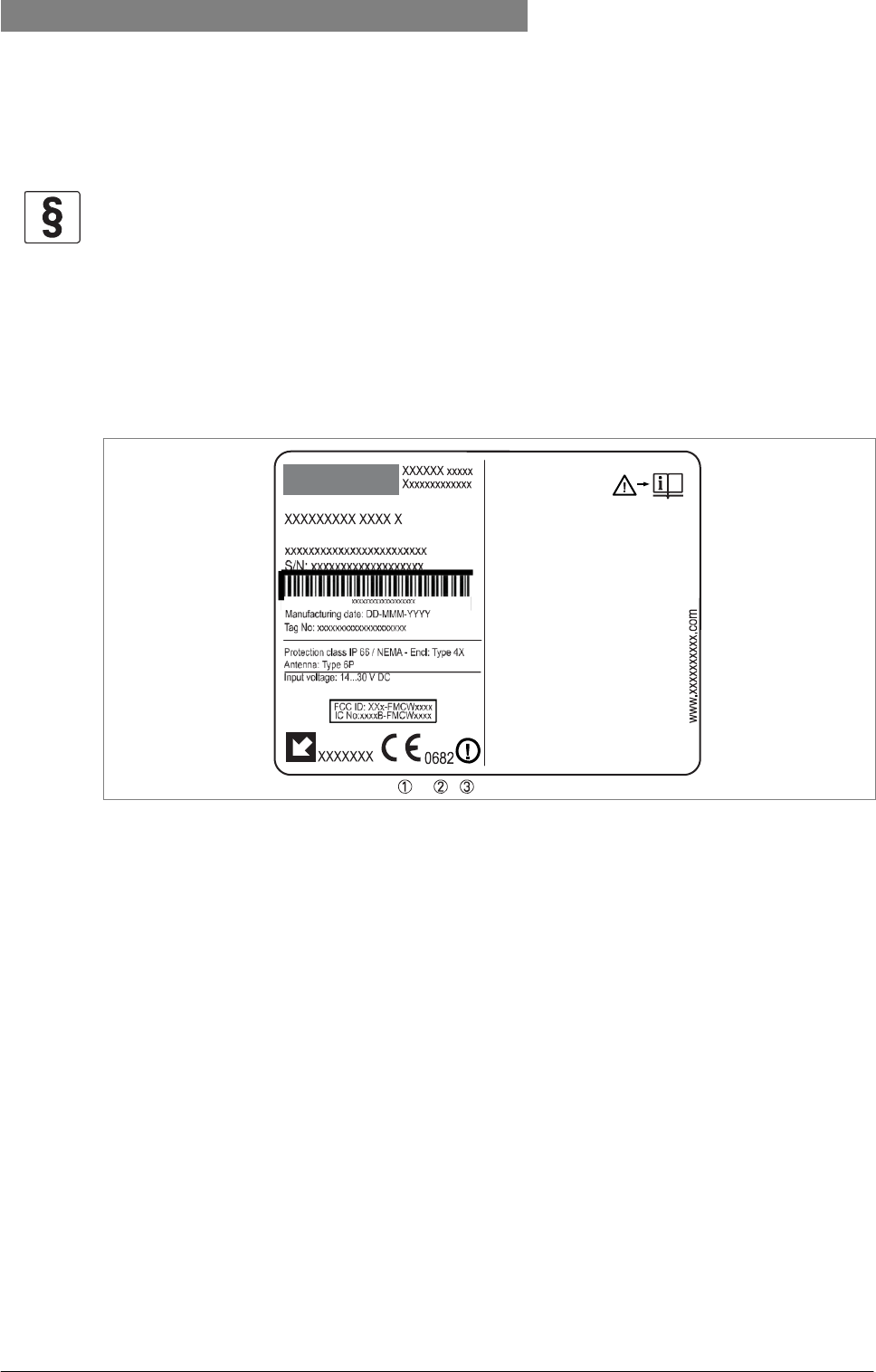
Figure 1-1: Radio approval information on the nameplate
1 CE sign
2 Notified body number (0682 = CETECOM)
3 Class II identifier
According to ETSI EN 302 372 (2006-04), the radiated power outside a metallic tank is less than
-30 dBm.
Refer also to the radio approval certificate on the internet site. The radio approval report is given on the CD-ROM supplied with the
device.

8
www.krohne.com
03/2012 - 4001904901 - HB OPTIWAVE 5200 R01 en
1
SAFETY
INSTRUCTIONS
OPTIWAVE 5200 C/F
1.4.2 U.S.A. and Canada
LEGAL
NOTICE!
This device complies with Part
15 of the
FCC Rules and with RSS-210
of
Industry
Canada.
Operation
is
subject
to the
following two
conditions:
1.
This device may
not
cause harmful interference,
and
2.
This device must accept any interference received, including interference which may cause
un-
desired
operation.
Changes
or
modifications made
to
this equipment
not
expressly approved
by the manufacturer
may void
the
FCC and
IC
authorizations
to
operate this
equipment.
This legal information is shown on a label on the rear side of the device.
The radio approval report is given on the CD-ROM supplied with the device. You can also download it from the internet site.
1.5 Safety instructions from the manufacturer
1.5.1 Copyright and data protection
The contents of this document have been created with great care. Nevertheless, we provide no guarantee that the contents are
correct, complete or up-to-date.
The contents and works in this document are subject to copyright. Contributions from third parties are identified as such.
Reproduction, processing, dissemination and any type of use beyond what is permitted under copyright requires written
authorisation from the respective author and/or the manufacturer.
The manufacturer tries always to observe the copyrights of others, and to draw on works created in-house or works in the public domain.
The collection of personal data (such as names, street addresses or e-mail addresses) in the manufacturer's documents is always
on a voluntary basis whenever possible. Whenever feasible, it is always possible to make use of the offerings and services without
providing any personal data.
We draw your attention to the fact that data transmission over the Internet (e.g. when communicating by e-mail) may involve gaps
in security. It is not possible to protect such data completely against access by third parties.
We hereby expressly prohibit the use of the contact data published as part of our duty to publish an imprint for the purpose of sending
us any advertising or informational materials that we have not expressly requested.

03/2012 - 4001904901 - HB OPTIWAVE 5200 R01 en
www.krohne.com
9
OPTIWAVE 5200 C/F SAFETY INSTRUCTIONS 1
1.5.2 Disclaimer
The manufacturer will not be liable for any damage of any kind by using its product, including, but not limited to direct, indirect or
incidental and consequential damages.
This disclaimer does not apply in case the manufacturer has acted on purpose or with gross negligence. In the event any applicable law
does not allow such limitations on implied warranties or the exclusion of limitation of certain damages, you may, if such law applies to
you, not be subject to some or all of the above disclaimer, exclusions or limitations.
Any product purchased from the manufacturer is warranted in accordance with the relevant product documentation and our
Terms and Conditions of Sale.
The manufacturer reserves the right to alter the content of its documents, including this disclaimer in any way, at any time, for any
reason, without prior notification, and will not be liable in any way for possible consequences of such changes.
10
www.krohne.com
03/2012 - 4001904901 - HB OPTIWAVE 5200 R01 en
1
SAFETY
INSTRUCTIONS
OPTIWAVE 5200 C/F
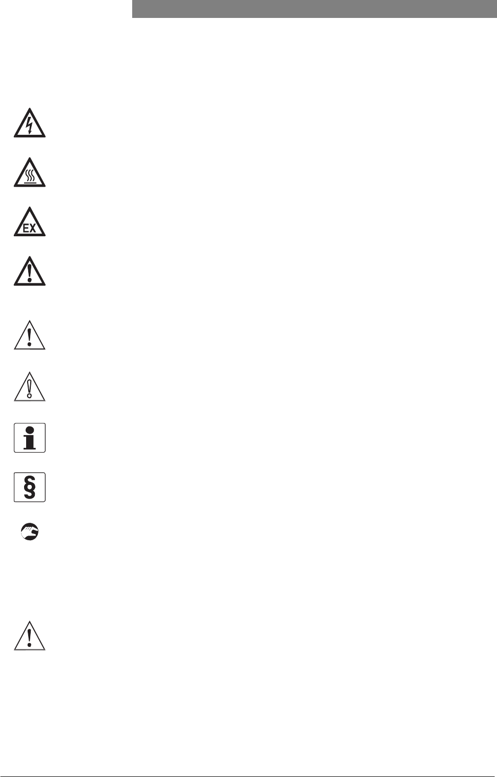
1.5.5 Warnings and symbols used
Safety warnings are indicated by the following symbols.
DANGER!
This information refers
to the
immediate danger when working with
electricity.
DANGER!
This warning refers
to the
immediate danger
of
burns caused
by
heat
or hot surfaces.
DANGER!
This warning refers
to
the immediate danger when using this device
in a
hazardous
atmosphere.
DANGER!
These warnings must
be
observed without fail. Even partial disregard
of
this warning can lead
to
serious health problems and even death. There
is
also
the
risk
of
seriously damaging
the device
or
parts
of the
operator's
plant.
WARNING!
Disregarding this safety warning, even
if
only
in
part, poses
the
risk
of
serious health
problems.
There
is
also
the
risk
of
damaging
the
device
or
parts
of the
operator's
plant.
CAUTION!
Disregarding these instructions can result
in
damage
to the
device
or to
parts
of the operator's
plant.
INFORMATION!
These instructions contain important information
for the
handling
of the device.
LEGAL
NOTICE!
This note contains information
on
statutory directives and
standards.
• HANDLING
This symbol designates all instructions for actions to be carried out by the operator in the specified sequence.
i
RESULT
This symbol refers to all important consequences of the previous actions.
1.6 Safety instructions for the operator
WARNING!
In
general, devices from
the
manufacturer may only
be
installed, commissioned, operated
and
maintained
by
properly trained and authorized
personnel.
This document
is
provided
to
help you establish operating conditions, which will permit safe
and
efficient use
of
this
device.

03/2012 - 4001904901 - HB OPTIWAVE 5200 R01 en
www.krohne.com
11
OPTIWAVE 5200 C/F DEVICE DESCRIPTION 2
2.2 Device description
The FMCW radar level transmitter is designed to measure the distance, level, mass, volume and reflectivity of liquids, pastes and
slurries. Radar level transmitters use an antenna to guide a signal to the surface of the measured product. Radar is a non-contact
technology. It is particularly suitable for the level measurement of corrosive products.
The signal converter of the device has 2 versions: Compact version
The signal converter is attached directly to the process connection and antenna.
Figure 2-2: Compact version
Remote version
The signal converter is installed away from the process connection and antenna (for example: at the bottom of a tank). The
communication cable between the signal converter and the antenna has a maximum length of 100 m / 328 ft.
Figure 2-3: Remote version

12
www.krohne.com
03/2012 - 4001904901 - HB OPTIWAVE 5200 R01 en
2
DEVICE
DESCRIPTION
OPTIWAVE 5200 C/F
The converter can be ordered with horizontal or vertical housing options for easy access to the device terminals and the optional
display.
Figure 2-4: Antenna options
1 PP Wave Horn antenna
2 PTFE Wave Horn antenna
3 Metallic Horn antenna (available sizes: DN80, DN100, DN150 and DN200)
4 Wave Guide antenna (Length options: 1...6 m / 3.28...19.68 ft, in increments of 0.5 m / 1.64 ft)
Antenna extensions are available for PTFE Wave Horn and Metallic Horn antenna options for difficult installation conditions.
A distance piece option is available for high-temperature applications (if the process connection temperature is more than +150°C /
+302°F).
Figure 2-5: Distance piece option
For more data, refer to
Technical data
on page 79. The device has a set-up wizard. You usually will not need this document to install,
set up and operate the device.
03/2012 - 4001904901 - HB OPTIWAVE 5200 R01 en
www.krohne.com
13
OPTIWAVE 5200 C/F INSTALLATION 3
3.5 Installation
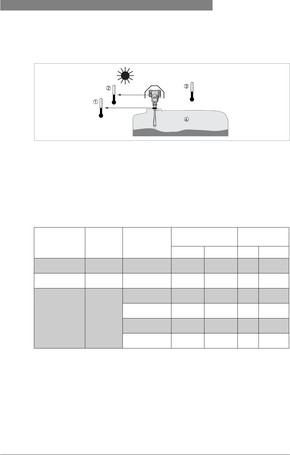
3.5.1 Pressure and temperature ranges
Figure 3-2: Pressure and temperature ranges
1 Flange temperature
Non-Ex devices: Depends on the type of antenna, process connection and the seal material. Refer to the table that fol- lows.
Ex devices: see supplementary operating instructions
2 Ambient temperature for operation of the display
-20...+60°C / -4...+140°F
If the ambient temperature is not between these limits, the display screen switches off automatically. The device con- tinues to operate.
3 Ambient temperature
Non-Ex devices: -40...+80°C / -40...+176°F
Ex devices: see supplementary operating instructions
4 Process pressure
Depends on the type of antenna and process connection. Refer to the table that follows.
Antenna type
Process
connection
Seal
Process connection
temperature
Process pressure
[°C]
[°F]
[barg]
[psig]
PP Wave Horn
G 1½;
1½ NPT
-
-20...+100
-4...+212
-1...16
1
-14.5...232
1
PTFE Wave Horn
Flange with
PTFE plate
-
-50...+150
-58...+302
-1...34
1
-14.5...493
1
Metallic Horn
Wave Guide
Flange
Metaglas® with
FKM/FPM
-40...+200
-40...+392
-1...40
1
-14.5...580
1
Metaglas® with
Kalrez® 6375
-20...+250
-4...+482
-1...40
1
-14.5...580
1
Metaglas® with
PFA
-60...+150
-76...+302
-1...40
1
-14.5...580
1
Metaglas® with
EPDM
-50...+130
-58...+266
-1...40
1
-14.5...580
1
1 Higher pressures on request
14
www.krohne.com
03/2012 - 4001904901 - HB OPTIWAVE 5200 R01 en
3
INSTALLATION
OPTIWAVE 5200 C/F
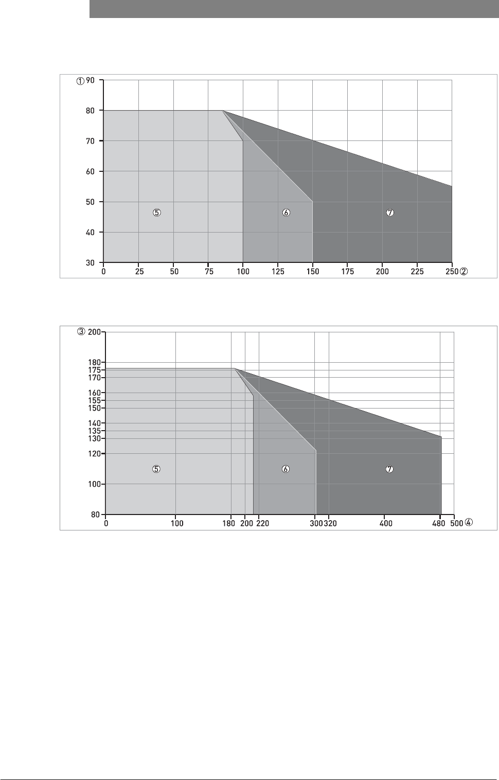
Figure 3-3: Ambient temperature / flange temperature, flange and threaded connection, in °C
Figure 3-4: Ambient temperature / flange temperature, flange and threaded connection, in °F
1 Maximum ambient temperature, °C
2 Maximum flange temperature, °C
3 Maximum ambient temperature, °F
4 Maximum flange temperature, °C
5 PP Wave Horn antenna
6 PTFE Wave Horn and Wave Guide antennas. Metallic Horn antenna (standard temperature version).
7 Metallic Horn antenna (high-temperature version)
For pressure rating data, refer to
Pressure ratings
on page 87.
03/2012 - 4001904901 - HB OPTIWAVE 5200 R01 en
www.krohne.com
15
OPTIWAVE 5200 C/F INSTALLATION 3
3.5.2 Mounting position (theoretical data for nozzle position)
CAUTION!
Follow
these
recommendations
to
make sure that
the
device measures
correctly.
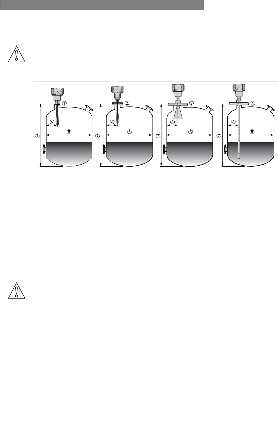
Figure 3-5: Recommended mounting position for liquids, pastes and slurries
1 Sockets for the PP Wave Horn antenna
2 Nozzles for the PTFE Wave Horn antenna
3 Nozzles or sockets for DN150 or DN200 Metallic Horn antennas
4 Nozzles or sockets for Wave Guide antennas
5 Tank diameter
6 Minimum distance of the nozzle or socket from the tank wall (depends on the antenna type and size - refer to items
1, 2 and 3 in this list):
1 1/7 × tank height
2 1/10 × tank height
3 There is no minimum distance from the Wave Guide antenna to metallic walls and other metal objects.
Maximum distance of nozzle from the tank wall (depends on the antenna type and size - refer to items 1, 2 and 3 in this list):
1 1/3 × tank diameter
2 1/3 × tank height
3 There is no maximum distance from the Wave Guide antenna to metallic walls and other metal objects.
7 Tank height
CAUTION!
Do not
put
the
device near
to the
product inlet.
If the
product that enters
the
tank touches
the
antenna,
the
device will measure incorrectly.
If the
product fills
the
tank directly below
the
antenna,
the
device will also measure
incorrectly.
16
www.krohne.com
03/2012 - 4001904901 - HB OPTIWAVE 5200 R01 en
3
INSTALLATION
OPTIWAVE 5200 C/F
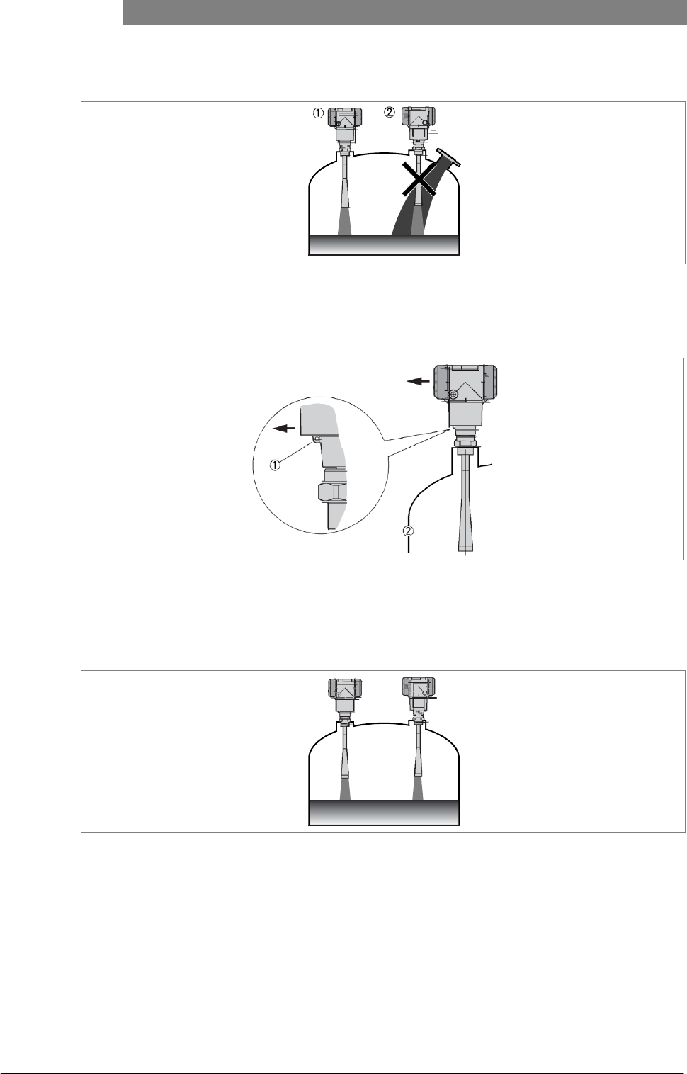
Figure 3-6: Product inlets
1 The device is in the correct position.
2 The device is too near to the product inlet.
Point the device in the correct direction
Figure 3-7: Point the device in the correct direction to get the best performance
Point the tag hole on the housing in the direction of the nearest tank wall.
1 Tag hole
2 Nearest tank wall
Figure 3-8: A maximum of 4 FMCW radar level meters can be operated in a tank
03/2012 - 4001904901 - HB OPTIWAVE 5200 R01 en
www.krohne.com
17
OPTIWAVE 5200 C/F INSTALLATION 3
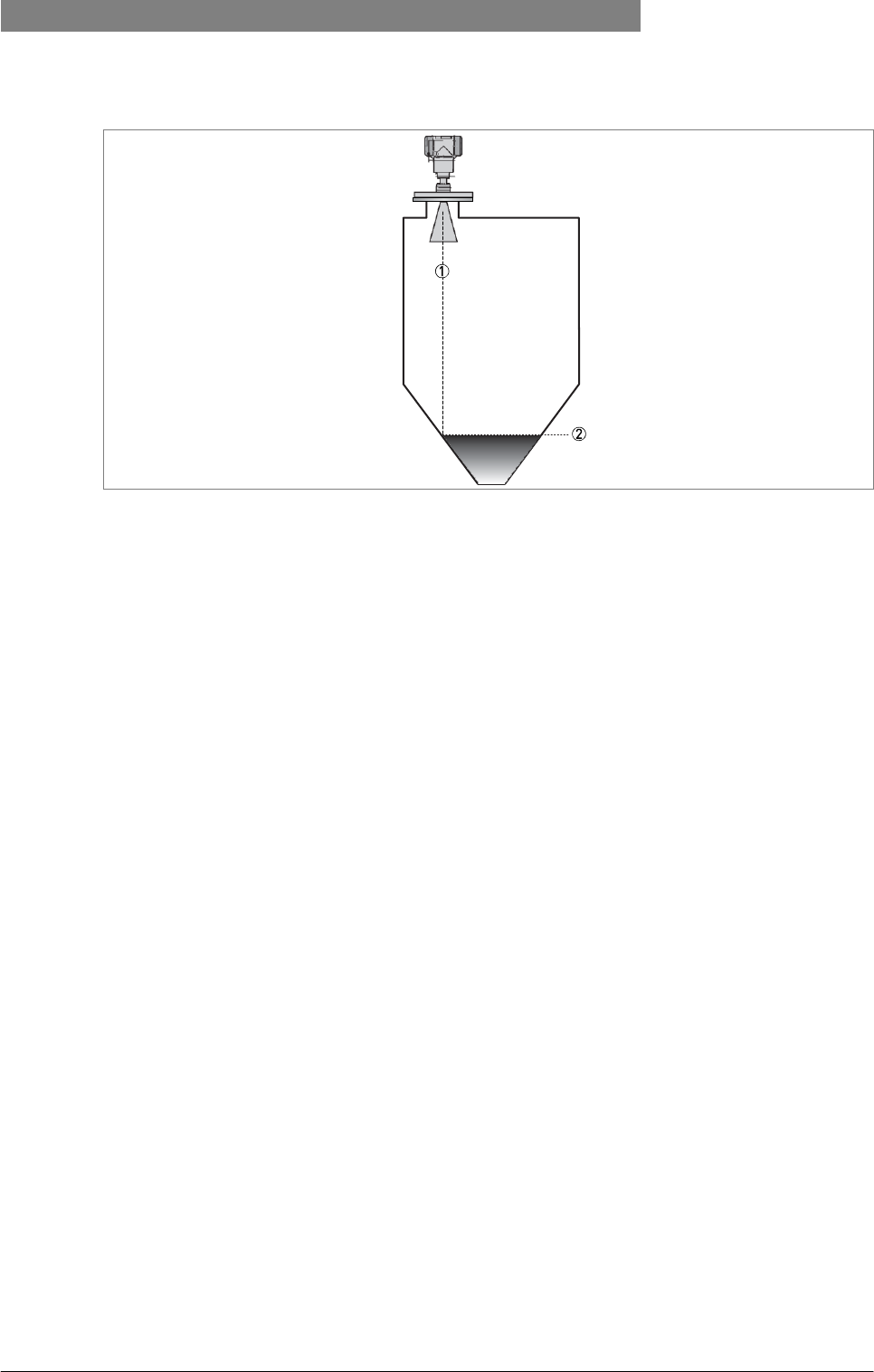
Figure 3-9: Tanks with tapered (conical etc.) bottoms
Tapered (conical etc.) bottoms have an effect on the measuring range. The device cannot measure to the bottom of the tank.
1 Radar beam
2 Minimum level reading
18
www.krohne.com
03/2012 - 4001904901 - HB OPTIWAVE 5200 R01 en
3
INSTALLATION
OPTIWAVE 5200 C/F
3.5.3 Mounting restrictions
CAUTION!
Follow these recommendations
to
make sure that
the
device measures
correctly.
We recommend that you prepare the installation when the tank is empty.
Mounting restrictions: General data
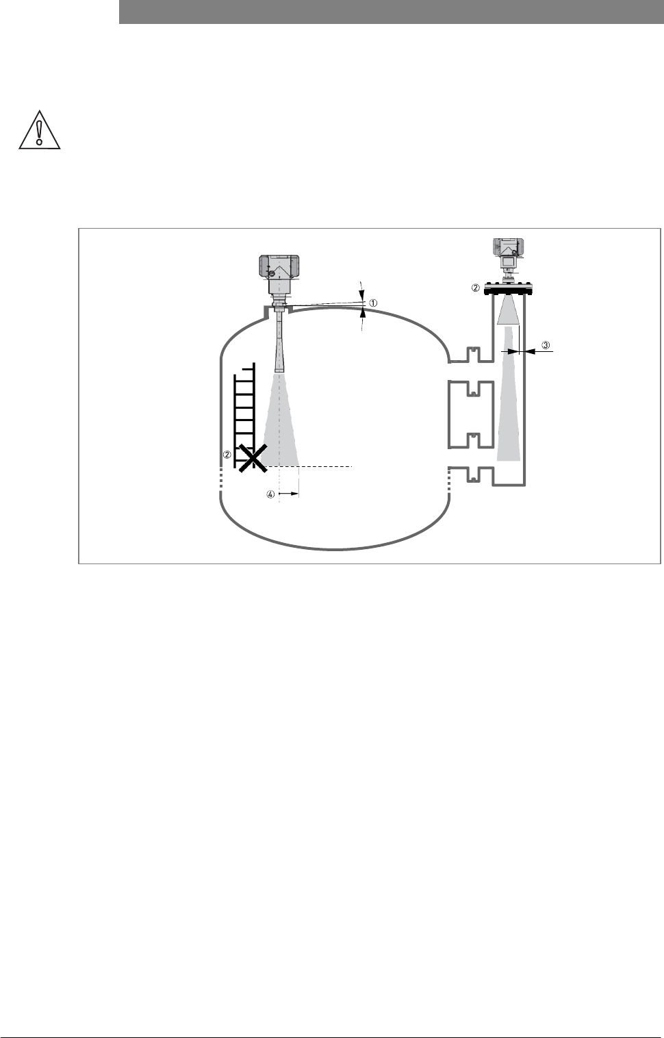
Figure 3-10: Mounting restrictions: General data
1 Do not tilt the device more than 2°
2 If there are too many obstacles in the radar beam, do an empty spectrum scan (refer to Operation) to remove parasitic signals with a filter. If necessary, install a
bypass chamber or stilling well or use an S-shaped extension or a 90° bend extension (the device must be installed on the side of the tank) to move the device away
from obstacles.
3 5 mm / 0.2¨ max. for high-dielectric constant liquids
4 Radius of radar footprint (Wave Guide antenna or DN80 and DN100 Metallic Horn antenna): no beam angle. The device transmits the radar signal along a tube of constant
diameter.
Radius of radar footprint (DN150 Metallic Horn antenna): increments of 140 mm/m or 1.7¨/ft (8°) Radius of radar footprint (DN200
Metallic Horn antenna): increments of 100 mm/m or 1.3¨/ft (6°)
Radius of radar footprint (PP Wave Horn and PTFE Wave Horn antenna): increments of 176 mm/m or 2.1¨/ft (10°)
03/2012 - 4001904901 - HB OPTIWAVE 5200 R01 en
www.krohne.com
19
OPTIWAVE 5200 C/F INSTALLATION 3
Obstacles in the tank
Figure 3-11: Obstacles in the tank
Do not put the device directly above obstacles (agitator, support beams, heating tubes etc.). Parasitic signals from obsta- cles will cause the device to measure
incorrectly.
1 Solution 1: Put the device on another process connection away from obstacles
2 Solution 2: Use the same process connection, but also use an S-shaped extension
3 Solution 3: Attach the device to the side of the tank and use a 90° bend extension
Devices with Metallic Horn antenna
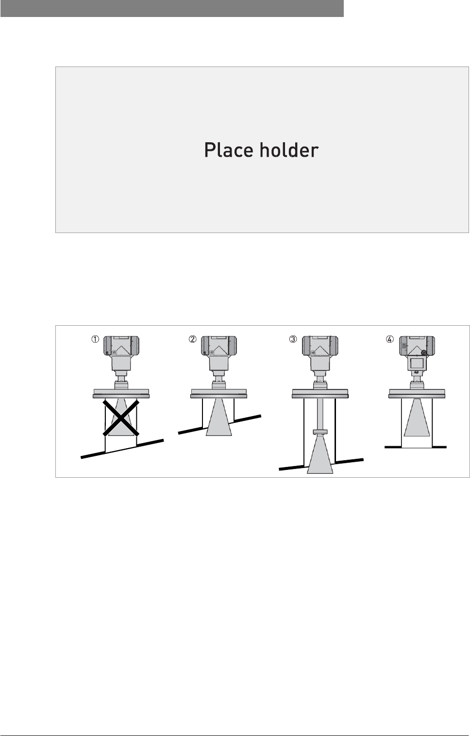
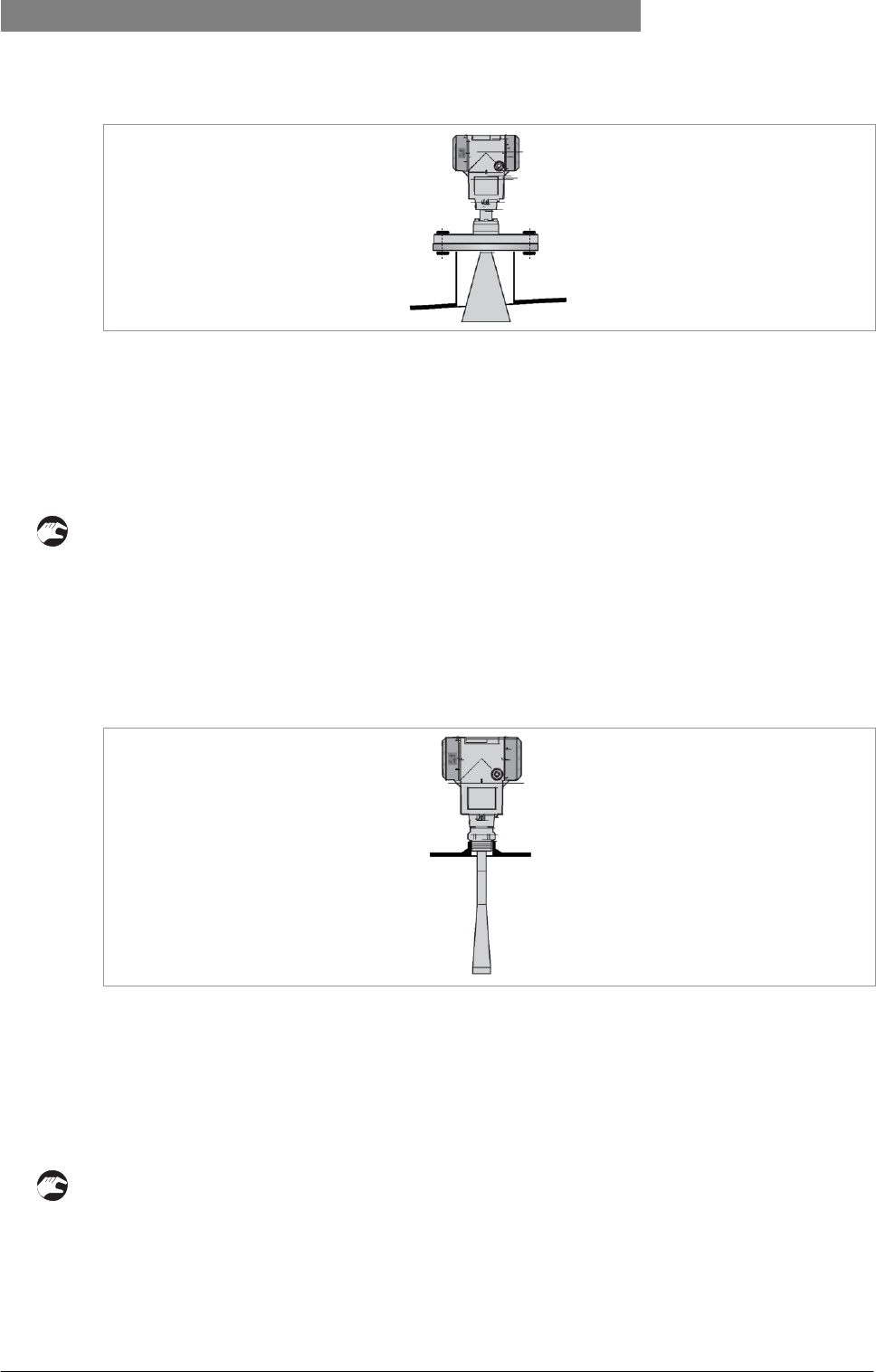
Figure 3-12: Devices with Metallic Horn antenna
1 If the roof is not flat, the antenna must project out of the nozzle
2 Short tank nozzle
3 Long tank nozzle (device with an antenna extension)
4 If the roof is flat (symmetrical tank fitting), it is not necessary for the antenna to project out of the nozzle
The antenna must project out of the nozzle. If necessary, use an antenna extension. If the tank fitting is symmetrical, it is not
necessary for the antenna to project out of the nozzle.
20
www.krohne.com
03/2012 - 4001904901 - HB OPTIWAVE 5200 R01 en
3
INSTALLATION
OPTIWAVE 5200 C/F
Devices with plastic Wave Horn antenna (PTFE, PP)
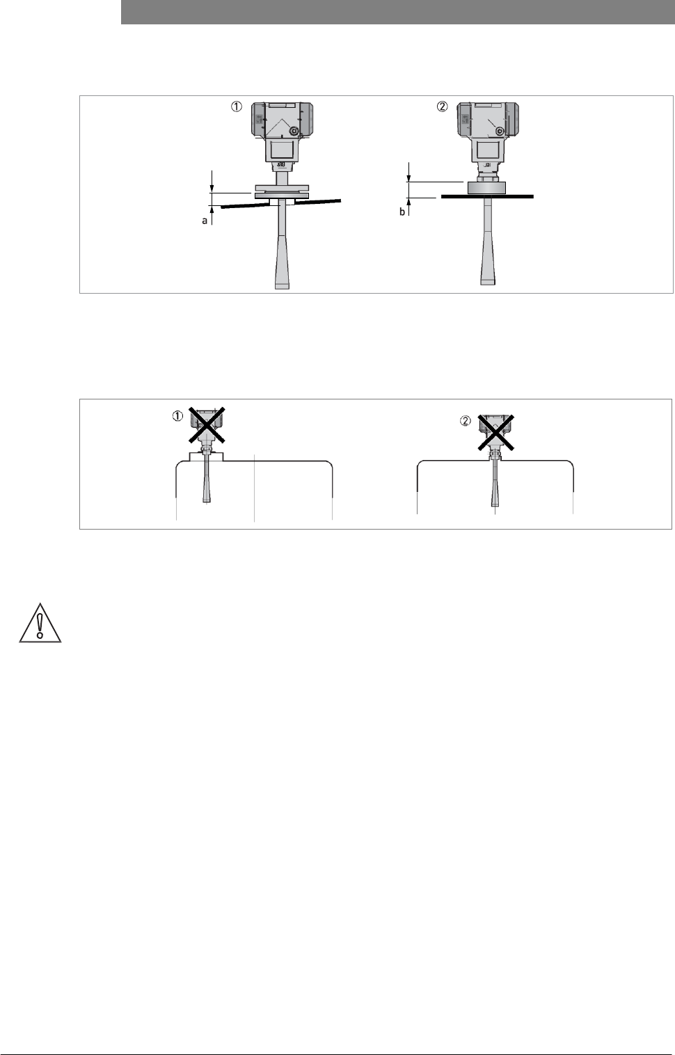
Figure 3-13: Devices with plastic Wave Horn antenna
a ≤ 44 mm / 1.7¨; b ≤ 40 mm / 1.6¨
1 Device with a PTFE Wave Horn antenna and a flange connection
2 Device with a PP Wave Horn antenna and a thread connection
Risk of mutliple reflections
Figure 3-14: Risk of mutliple reflections
1 Do not install on the centerline of a manhole cover
2 If possible, do not install a nozzle on the tank centerline
CAUTION!
If
there
are
parasitic signals,
the
device will
not
measure
correctly.
Parasitic signals
are
caused
by:
•
Objects
in the tank.
•
Sharp corners that are perpendicular
to the
path
of the beam.
•
Sudden changes
in
tank diameter
in the
path
of the beam.
03/2012 - 4001904901 - HB OPTIWAVE 5200 R01 en
www.krohne.com
21
OPTIWAVE 5200 C/F INSTALLATION 3
Requirements for flange connections
Figure 3-15: Flange connection
Equipment needed:
• Device
• Flange gasket (not supplied)
• Wrench (not supplied)
• Make sure the flange on the nozzle is level.
• Make sure that you use the applicable gasket for the flange dimensions and the process.
• Align the gasket correctly on the flange facing of the nozzle.
• Lower the antenna carefully into the tank.
• Make sure that you point the device in the correct direction. Refer to "Point the device in the correct direction" in this section.
• Tighten the flange bolts.
i
Refer to local rules and regulations for the correct torque to apply to the bolts.
Requirements for threaded connections
Figure 3-16: Threaded connection
Equipment needed:
• Device
• Gasket for G 1½ connection (not supplied)
• 50 mm / 2¨ wrench (not supplied)
• Make sure the tank connection is level.
• Make sure that you use the applicable gasket for the connection dimensions and the process.
• Align the gasket correctly.
• Lower the antenna carefully into the tank.
• Turn the threaded connection on the housing to attach the device to the process connection.
22
www.krohne.com
03/2012 - 4001904901 - HB OPTIWAVE 5200 R01 en
3
INSTALLATION
OPTIWAVE 5200 C/F
• Make sure that you point the device in the correct direction. Refer to "Point the device in the correct direction" in this section.
• Tighten the connection.
i
Refer to local rules and regulations for the correct torque to apply to the connection.
3.5.4 Standpipes (stilling wells and bypass chambers)
Use a standpipe if:
• There is highly conductive foam in the tank.
• The liquid is very turbulent or agitated.
• There are too many other objects in the tank.
• The device is measuring a liquid (petro-chemicals) in a tank with a floating roof.
• The device is installed in a horizontal cylindrical tank (refer to the end of this section)
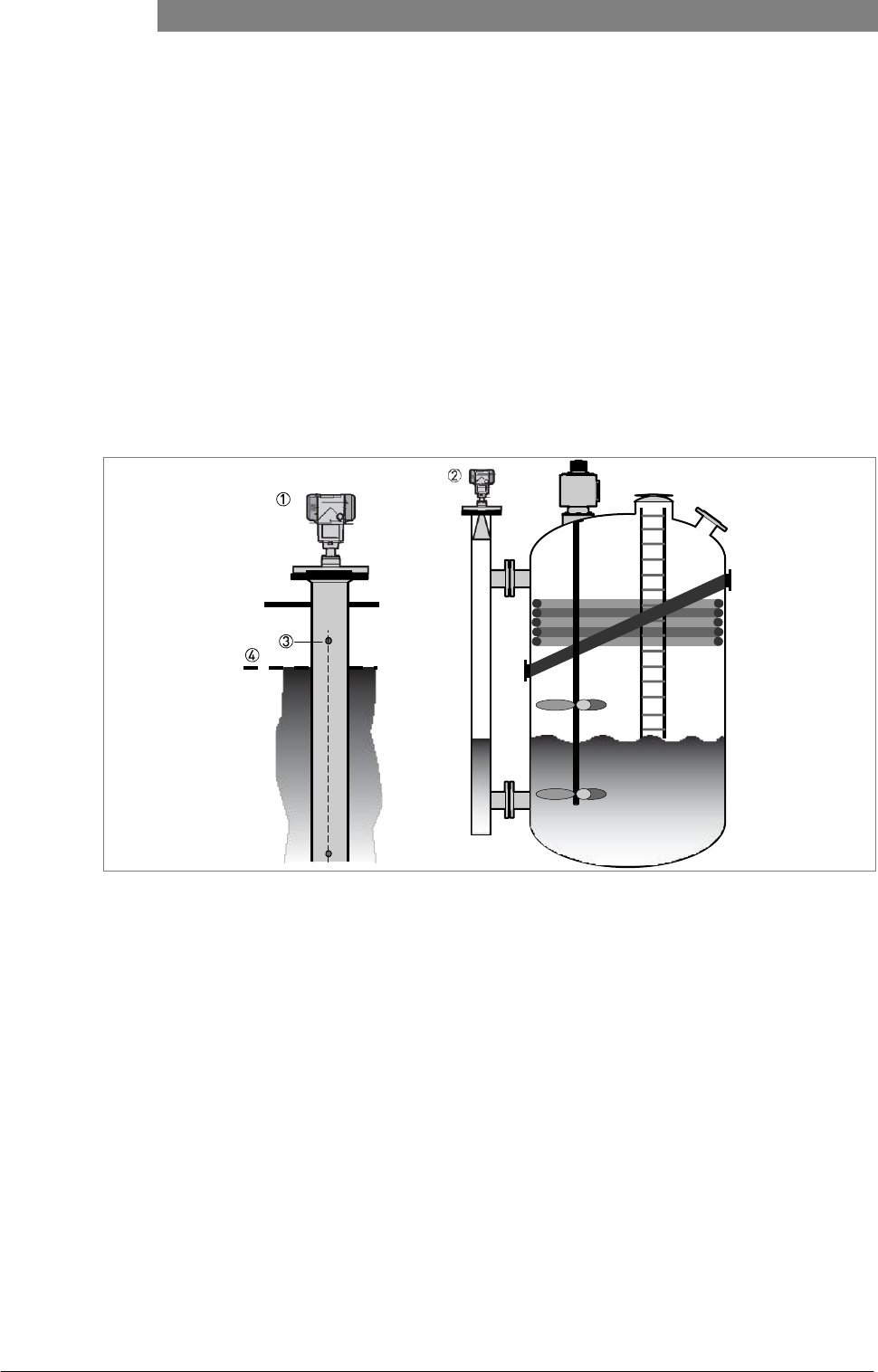
Figure 3-17: Installation recommendations for standpipes (stilling wells and bypass chambers)
1 A stilling well solution
2 A bypass chamber solution
3 Air circulation hole
4 Level of the liquid

03/2012 - 4001904901 - HB OPTIWAVE 5200 R01 en
www.krohne.com
23
OPTIWAVE 5200 C/F INSTALLATION 3
CAUTION!
Installation
requirements
•
The standpipe must
be
electrically
conductive.
•
The inside diameter
of the
standpipe must
not be
more than
5
mm
/
0.2
¨
over
the
diameter
of the
antenna (for
a
high-dielectric
constant
liquid).
•
The standpipe must
be
straight. There must
be no
sudden changes
in
internal
diameter
greater than
1
mm
/ 0.04¨.
•
The standpipe must
be vertical.
•
Recommended surface roughness: <
±
0.1 mm
/ 0.004¨.
•
Stilling well only: The bottom
of the
stilling well must
be open.
•
Make sure that there
are no
deposits
at the
bottom
of the standpipe.
•
Make sure that there
is
liquid
in the standpipe.
Stilling wells - general notes
Installation in tanks containing one liquid and foam
• Drill an air circulation hole (max. Ø10 mm / 0.4¨) in the stilling well above the maximum level.
• Remove the burr from the hole.
Installation in tanks containing one liquid or more without foam
• Drill an air circulation hole (max. Ø10 mm / 0.4¨) in the stilling well above the maximum level.
• Drill 1 or more liquid circulation holes in the stilling well (if there is more than 1 liquid in the tank).
i
These holes help the liquid to move freely between the stilling well and the tank.
• Remove the burr from the hole.
24
www.krohne.com
03/2012 - 4001904901 - HB OPTIWAVE 5200 R01 en
3
INSTALLATION
OPTIWAVE 5200 C/F
Stilling wells: floating roofs
If the device must be installed on a tank with a floating roof, install it in a stilling well.
Figure 3-18: Floating roofs
1 Sediment
2 Support fixtures
3 Stilling well
4 Floating roof
5 Product
6 Tank
Stilling wells: horizontal cylindrical tanks
We recommend that you install the device in a stilling well if the device:
• is for a horizontal cylindrical tank,
• is in a metallic tank,
• measures a product with a high dielectric constant and
• is on the centerline of the tank.
03/2012 - 4001904901 - HB OPTIWAVE 5200 R01 en
www.krohne.com
25
OPTIWAVE 5200 C/F INSTALLATION 3
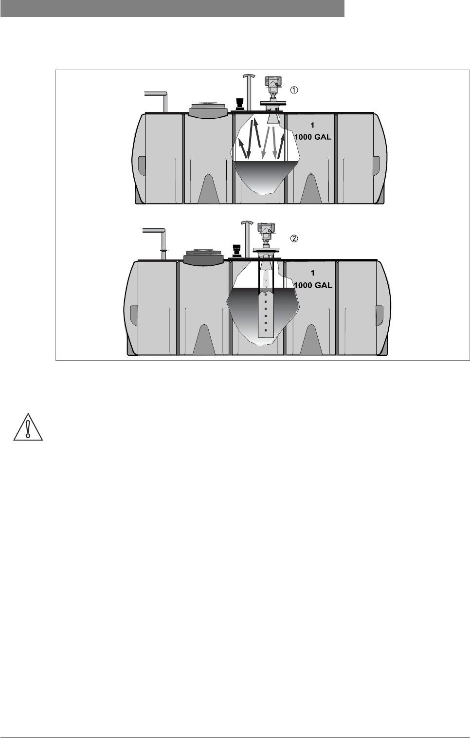
Figure 3-19: Horizontal cylindrical tanks
1 The device is installed without a stilling well. There are multiple reflections. Refer to the CAUTION! that follows.
2 The device is installed in a stilling well and measures correctly.
CAUTION!
If the
device
is
installed
in
horizontal cylindrical tank that contains
a
high dielectric
constant
liquid without
a
stilling well,
do not put it on the
tank centerline. This will cause
multiple
reflections and
the
device will
not
measure accurately. Use
the
2.3.12 Multiple
Reflections
function
in
Supervisor
>
Basic Parameters
to
keep
the
effects
of
multiple reflections
to a
minimum. For more data, refer
to
Function description
on
page
58 (2. Supervisor).
Bypass chambers
Installation next to tanks containing one liquid and foam
• The top process connection of the bypass chamber must be above the maximum level of liquid.
• The bottom process connection of the bypass chamber must be below the lowest measured level of liquid.
Installation next to tanks containing more than one liquid
• The top process connection of the bypass chamber must be above the maximum level of liquid.
• The bottom process connection of the bypass chamber must be below the lowest measured level of liquid.
26
www.krohne.com
03/2012 - 4001904901 - HB OPTIWAVE 5200 R01 en
3
INSTALLATION
OPTIWAVE 5200 C/F
• Additional process connections are necessary for the liquids to circulate freely along the length of the bypass chamber.
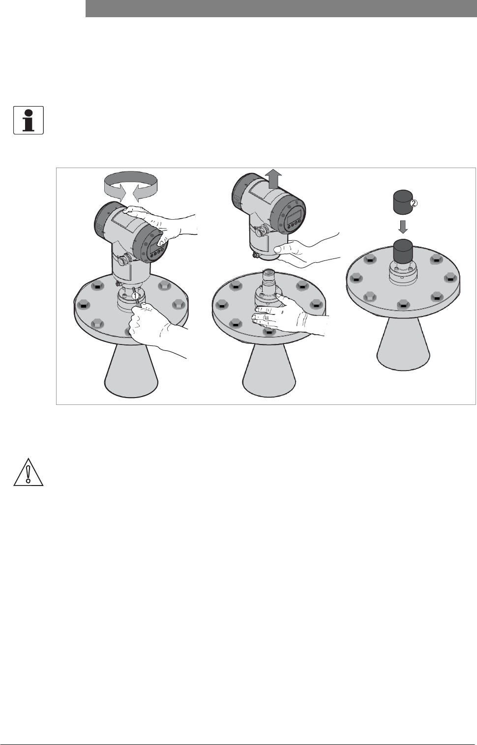
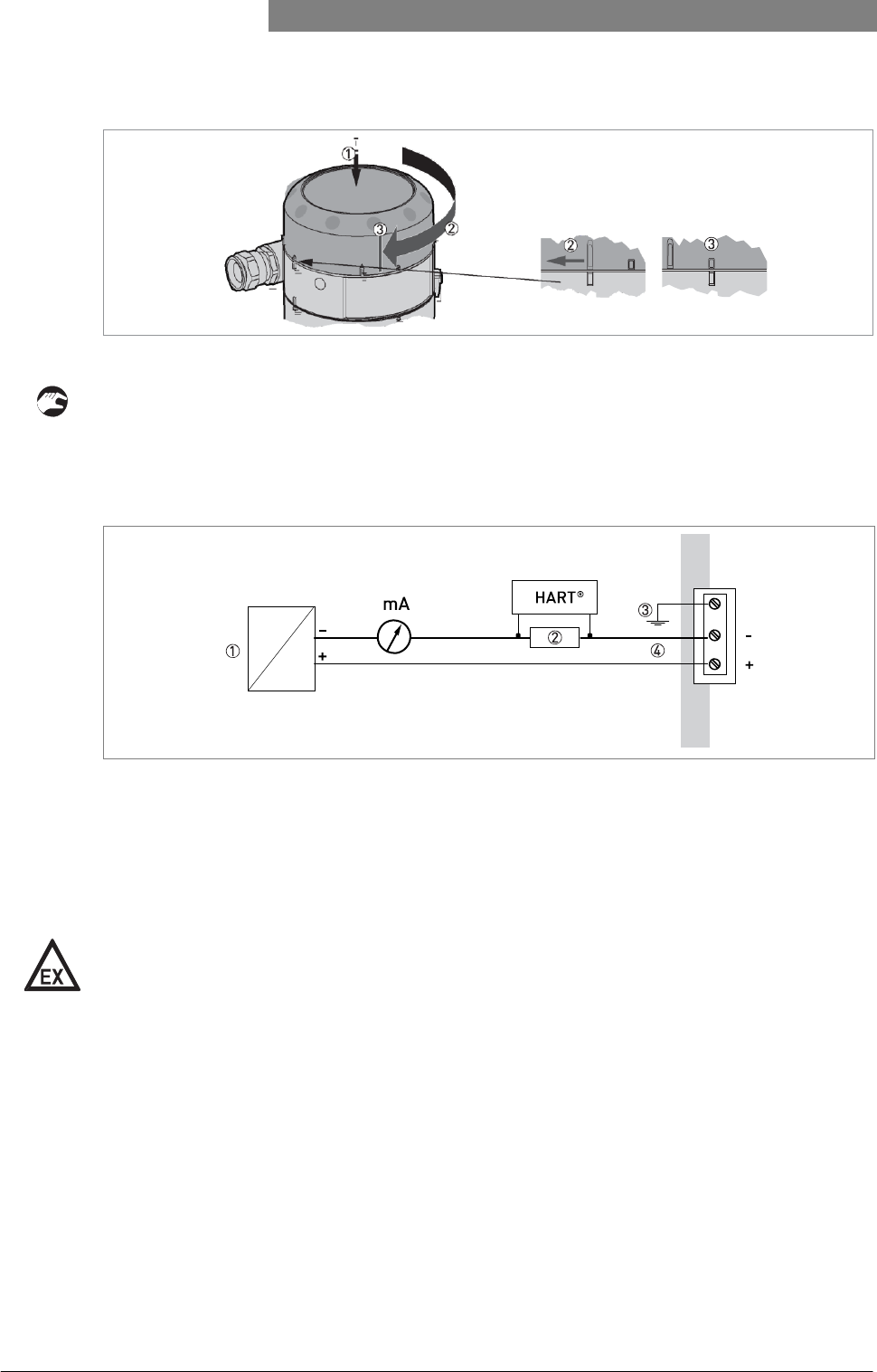
3.5.5 How to turn or remove the signal converter
INFORMATION!
The converter turns
360°.
Figure 3-20: How to turn or remove the signal converter
1 Tool: 5 mm Allen wrench (not supplied)
2 Cover for the coaxial hole on top of the process connection assembly (not supplied)
CAUTION!
If
you remove
the
housing, put
a
cover
on the
coaxial hole
on top of the
process
connection
assembly.
When
the
housing
is
attached
to the
process connection assembly, tighten
the
lock
screw.
03/2012 - 4001904901 - HB OPTIWAVE 5200 R01 en
www.krohne.com
27
OPTIWAVE 5200 C/F INSTALLATION 3
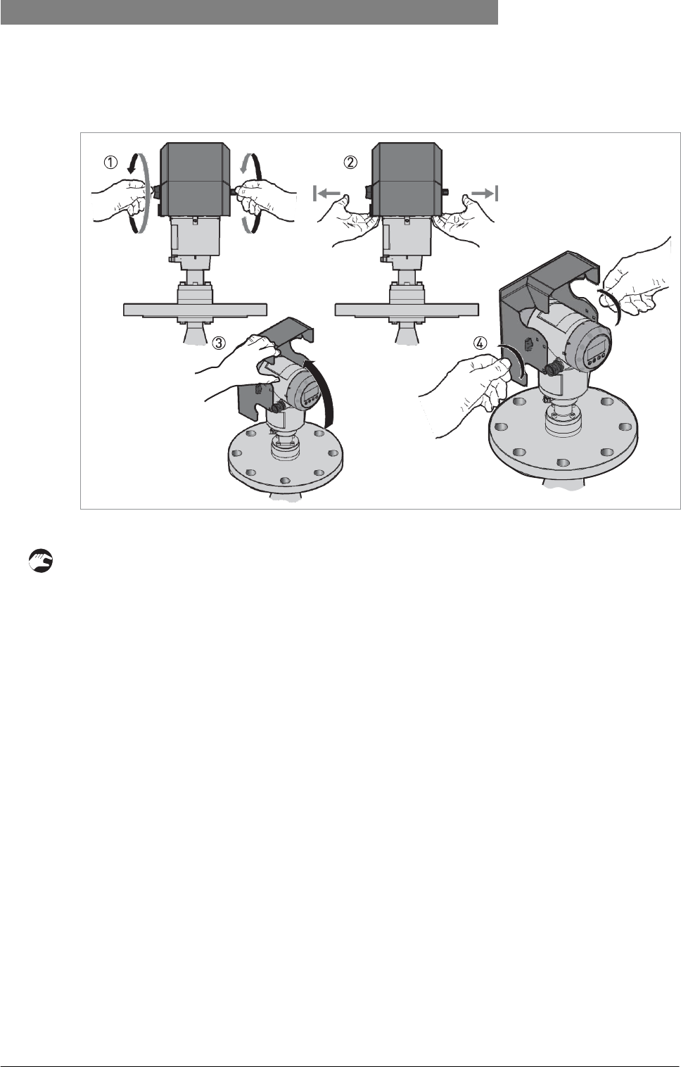
3.5.6 How to open the weather protection
Figure 3-21: How to open the weather protection
1 Loosen the bolt on each side of the weather protection.
2 Pull the sides of the weather protection out of the notch for the closed position.
3 Pull the weather protection up and back.
i
This will open the weather protection.
4 Tighten the bolts to lock the weather protection in its open position.
28
www.krohne.com
03/2012 - 4001904901 - HB OPTIWAVE 5200 R01 en
4
ELECTRICAL
CONNECTIONS
OPTIWAVE 5200 C/F
4.1 Safety instructions
DANGER!
All work on the electrical connections may only be carried out with the power disconnected.
Take
note
of the
voltage data
on the nameplate!
DANGER!
Observe
the
national regulations
for
electrical
installations!
DANGER!
For devices used
in
hazardous areas, additional safety notes apply; please refer
to the Ex
documentation.
WARNING!
Observe without
fail the
local occupational health and safety regulations. Any work done
on the
electrical components
of the
measuring device may only
be
carried
out by
properly
trained
specialists.
INFORMATION!
Look
at the
device nameplate
to
ensure that
the
device
is
delivered according
to
your
order.
Check
for the
correct supply voltage printed
on the nameplate.
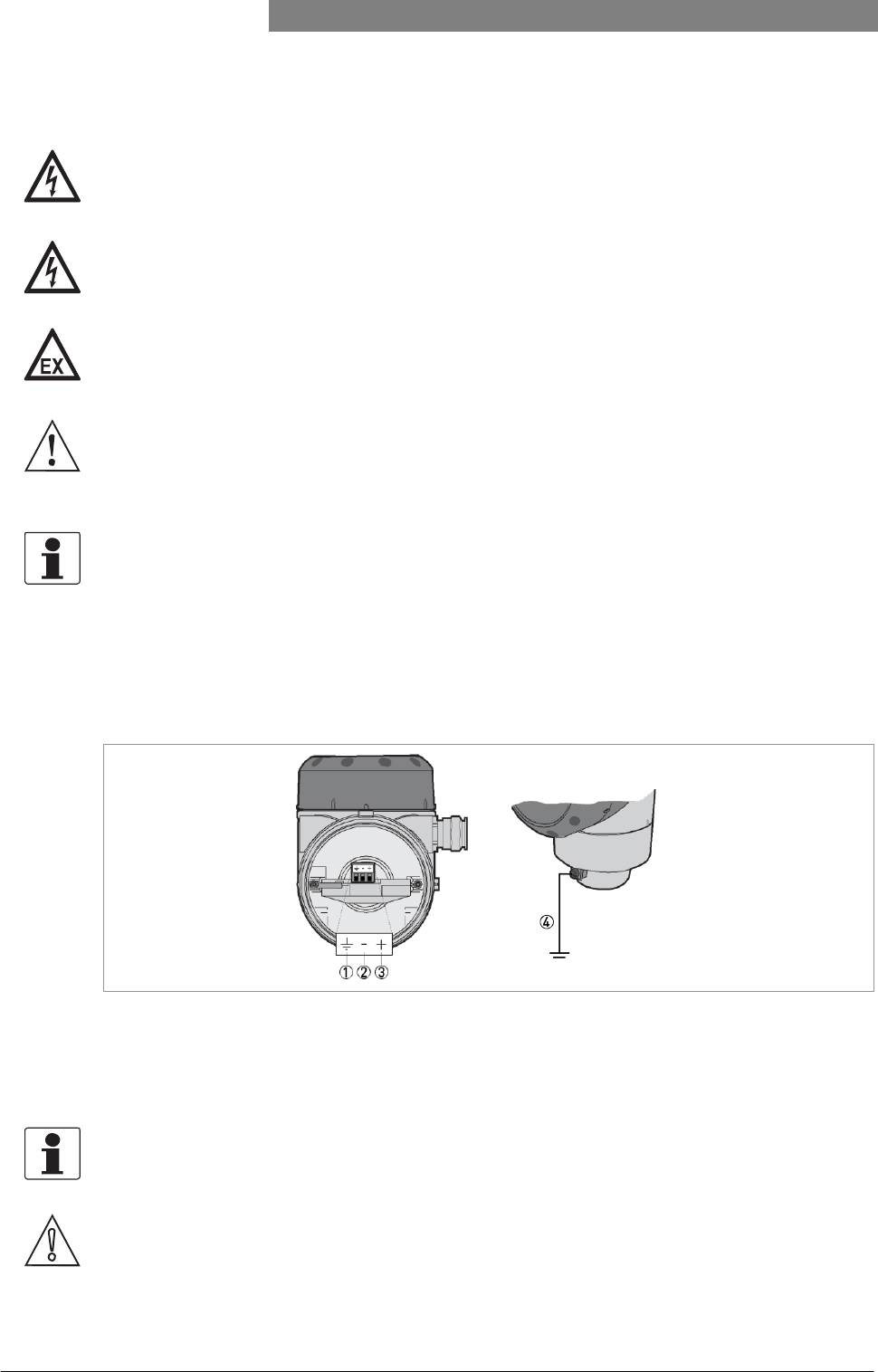
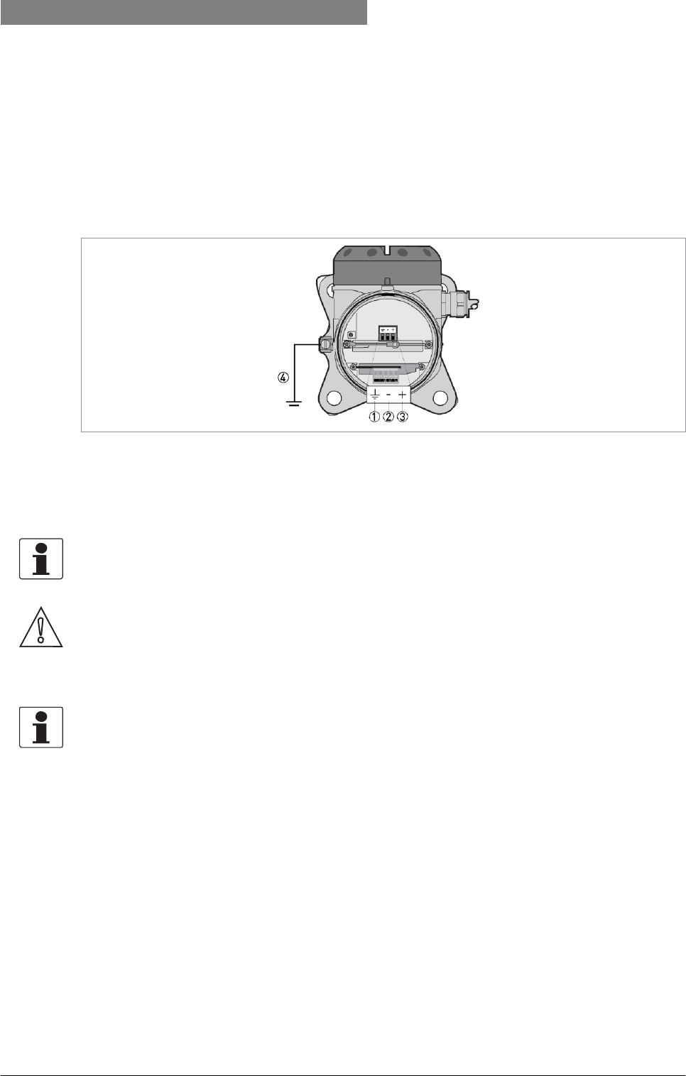
4.2 Electrical installation: compact version
Figure 4-1: Terminals for electrical installation
1 Grounding terminal in the housing (if the device is grounded)
2 Current output -
3 Current output +
4 Location of the external grounding terminal (at the bottom of the converter)
INFORMATION!
The output energizes
the
device and
is
used
for
HART
®
communication.
CAUTION!
Make sure that
the
polarity
of the
power supply
is correct.
03/2012 - 4001904901 - HB OPTIWAVE 5200 R01 en
www.krohne.com
29
OPTIWAVE 5200 C/F ELECTRICAL CONNECTIONS 4
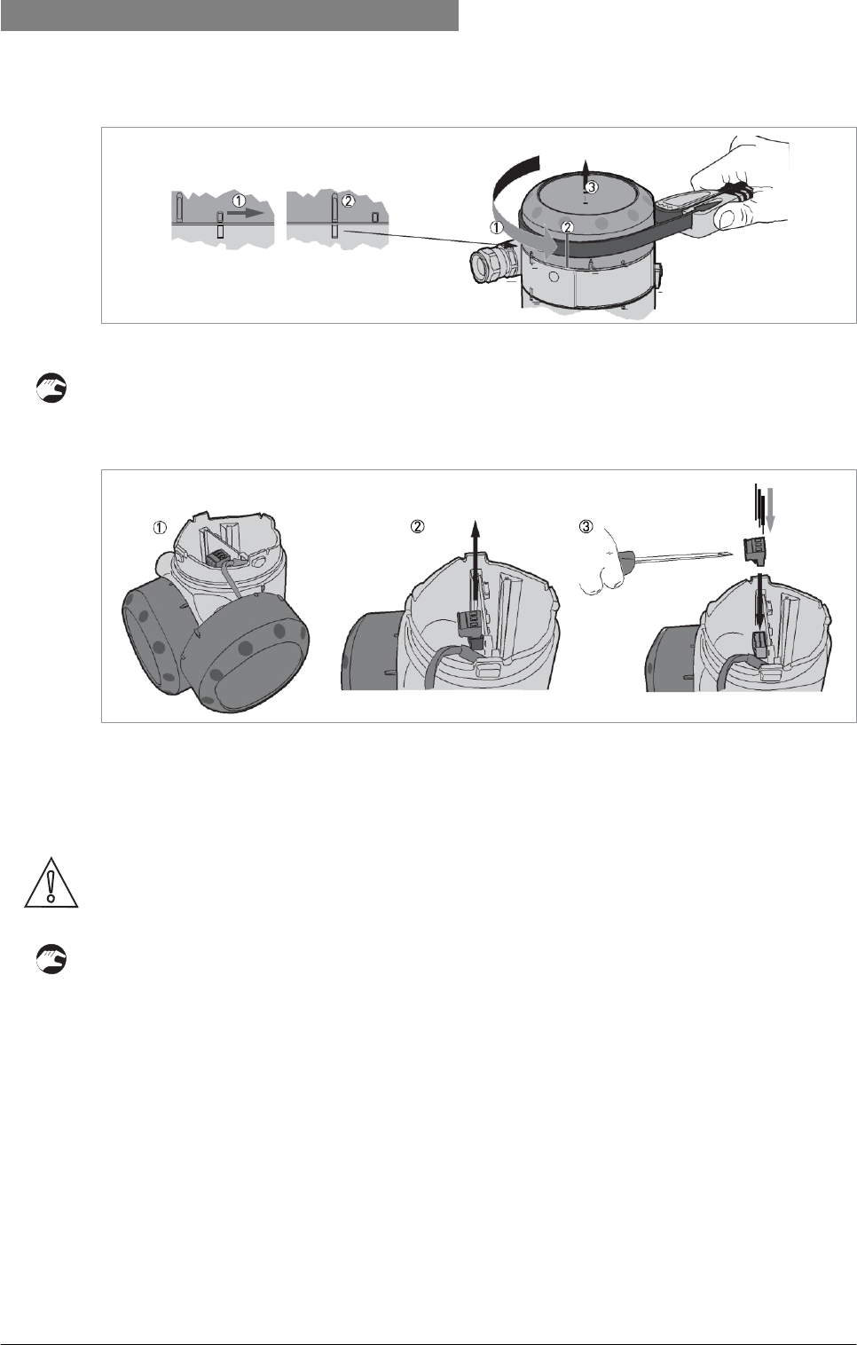
Figure 4-2: How to open the terminal compartment cover
• Turn the cover counterclockwise with a strap wrench.
• Remove the cover.
Figure 4-3: Procedure for electrical installation
Equipment needed:
• Small slotted tip screwdriver (not supplied)
CAUTION!
Make sure that
the
polarity
of the
wires
is correct.
Procedure:
1 Do not disconnect the safety cord from the terminal compartment cover. Put the terminal compartment cover adjacent to the
housing.
2 Remove the connector from the circuit board.
3 Connect the electrical wires to the connector. Attach the connector to the circuit board. Tight- en the cable entry glands.
30
www.krohne.com
03/2012 - 4001904901 - HB OPTIWAVE 5200 R01 en
4
ELECTRICAL
CONNECTIONS
OPTIWAVE 5200 C/F
Figure 4-4: How to close the terminal compartment cover
• Attach the cover.
• Turn the cover clockwise.
4.2.1 Non-Ex devices
Figure 4-5: Electrical connections for non-Ex devices
1 Power supply
2 Resistor for HART® communication
3 Optional connectional to the grounding terminal
4 Output: 12...30 VDC for an output of 22 mA at the terminal
4.2.2 Devices for hazardous locations
DANGER!
For electrical data for device operation
in
hazardous locations, refer
to
the related certificates
of
compliance and supplementary instructions (ATEX, IECEx, cFMus,
...).
You can find
this
documentation
on the
CD-ROM delivered with
the
device
or it
can
be
downloaded free
of charge
from
the
website (Download
Center).
4.2.3 PROFIBUS PA
For electrical data for PROFIBUS PA networks, refer to the PROFIBUS PA supplement. You can find this documentation on the CD-ROM
delivered with the device or it can be downloaded free of charge from the website (Downloadcenter).
4.2.4 FOUNDATION Fieldbus
For electrical data for FOUNDATION Fieldbus networks, refer to the FOUNDATION Fieldbus supplement. You can find this documentation
on the CD-ROM delivered with the device or it can be downloaded free of charge from the website (Downloadcenter).
03/2012 - 4001904901 - HB OPTIWAVE 5200 R01 en
www.krohne.com
31
OPTIWAVE 5200 C/F ELECTRICAL CONNECTIONS 4
4.3 Remote device version
4.3.1 General notes
To be
defined.
4.3.2 Electrical installation: remote version
Figure 4-6: Terminals for electrical installation
1 Grounding terminal in the housing (if the device is grounded)
2 Current output -
3 Current output +
4 Location of the external grounding terminal (on the wall support)
INFORMATION!
The output energizes
the
device and
is
used
for
HART
®
communication.
CAUTION!
Make sure that
the
polarity
of the
power supply
is correct.
4.3.3 Requirements for communication cables supplied by the customer
INFORMATION!
The communication cable
is an
option
for
non-Ex devices. Ex-approved cable
is
supplied
with
devices
for
hazardous
locations.
Non-Ex devices only: If the communication cable is not supplied by the device manufacturer, the cable must have properties that follow:
Basic properties
• Twisted cable 2 by 2 or
quad-twisted,
PVC insulated core, shielded or screened with 65...100%
coverage. The PVC jacket must agree with DIN EN 50290-2-22 and the RoHS Directive
2002/95/EC. The communication cable must not contain any halogens, must be unplasticized, and must stay flexible at low
temperatures.

32
www.krohne.com
03/2012 - 4001904901 - HB OPTIWAVE 5200 R01 en
4
ELECTRICAL
CONNECTIONS
OPTIWAVE 5200 C/F
Maximum length of the communication cable
• Non-Ex applications: 100 m / 328 ft
• Ex applications: refer to the supplementary operating instructions or approval certificates.
Use the Ex-approved cable supplied with the
device!
Temperature
• Use electrical cable with the applicable temperature rating for the operating conditions.
• Ambient temperature range: -40...+80°C / -40...+175°F
Dimensions of the insulated conductors
• Min.-max. cross-sectional area of the conductors: 4×0.326...4×2.5 mm² (22....14 AWG), shielded cable
• Use the applicable cable glands for the cable entry openings in the housing.
• Use the applicable cable for the cable glands.
Electrical characteristics
• Test voltage: Insulated conductor / shield (screen) ≥ 500 VAC
• Line resistance: >55 Ω/km
• The cable must agree with EN 60811 (Low Voltage Directive) or equivalent national regulations.
Twist rate of the insulated conductors
• The minimum twist rate is 10 twists per metre, to prevent interference from external electromagnetic fields.

03/2012 - 4001904901 - HB OPTIWAVE 5200 R01 en
www.krohne.com
33
OPTIWAVE 5200 C/F ELECTRICAL CONNECTIONS 4
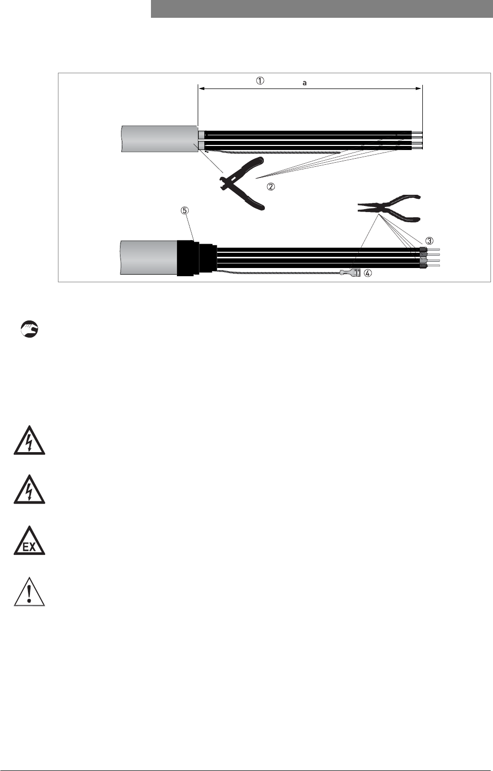
4.3.4 How to prepare a communication cable supplied by the customer
Figure 4-7: Equipment needed to prepare the communication cable
1 Communication cable (supplied on request)
2 2 heat-shrinkable sleeves for the PVC jacket (not supplied)
3 8 ferrules for the end of the conductors (not supplied)
4 2 Faston connectors for the drain wires
5 Wire stripper (not supplied)
6 Crimping pliers (not supplied)
INFORMATION!
•
The Faston connector
for the
stranded drain wire must agree with DIN
46
228:
E 1.5-8
•
The wire end ferrules
for the
twisted pair
of
conductors must agree with DIN
46
228:
E 0.5-8
34
www.krohne.com
03/2012 - 4001904901 - HB OPTIWAVE 5200 R01 en
4
ELECTRICAL
CONNECTIONS
OPTIWAVE 5200 C/F
Figure 4-8: How to prepare the communication cable
a = 50 mm / 2¨
1 Remove the PVC jacket from the wire to dimension "a".
2 Remove the insulation from the wire. Obey national regulations for electrical wiring.
3 Crimp the wire end ferrules on the conductors.
4 Crimp the Faston connectors on the drain wires.
5 Install a heat-shrinkable sleeve on the PVC jacket.
4.3.5 How to connect the communication cable to the device
DANGER!
Cables may only
be
connected when
the
power
is
switched
off.
DANGER!
The device must
be
grounded
in
accordance with regulations
in
order
to
protect
personnel
against electric
shocks.
DANGER!
For devices used
in
hazardous areas, additional safety notes apply; please refer
to the Ex
documentation.
WARNING!
Observe without
fail the
local occupational health and safety regulations. Any work done
on the
electrical components
of the
measuring device may only
be
carried
out by
properly
trained
specialists.
03/2012 - 4001904901 - HB OPTIWAVE 5200 R01 en
www.krohne.com
35
OPTIWAVE 5200 C/F ELECTRICAL CONNECTIONS 4
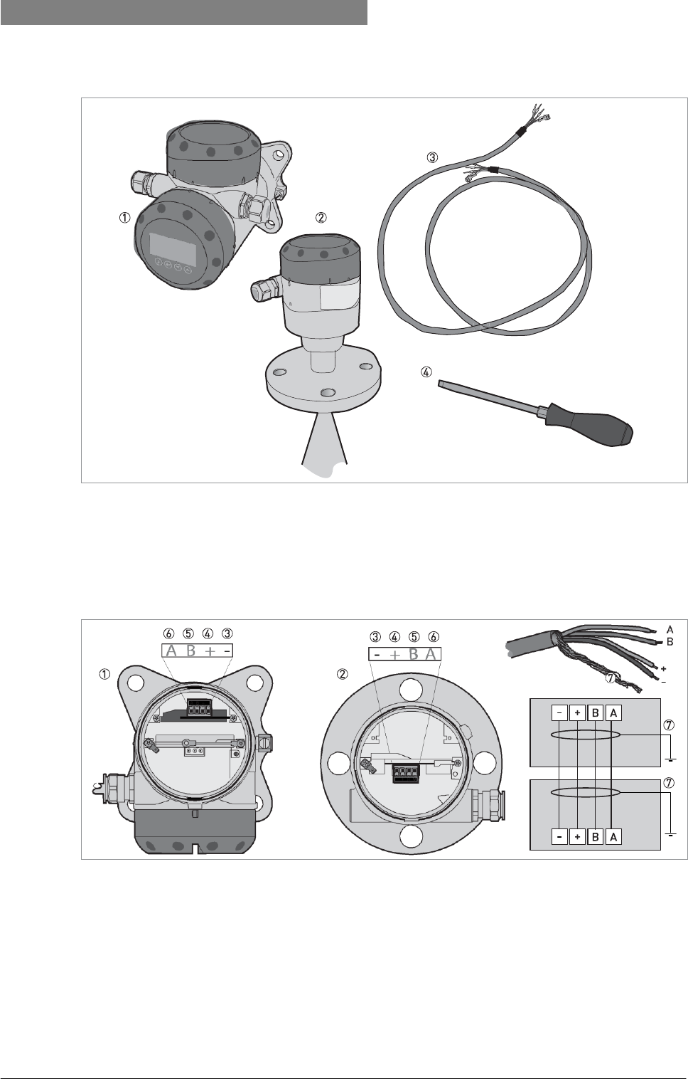
Equipment needed
Figure 4-9: Equipment needed to prepare the communication cable
1 Remote coverter
2 Antenna housing
3 Communication cable (supplied on request for non-Ex devices) - for more data, refer to
How
to
prepare
a communi-
cation cable supplied
by
the customer
on page
38
4 Small slotted-tip screwdriver (not supplied)
Connection diagram
Figure 4-10: Connections between the remote converter and the antenna housing
1 Remote coverter
2 Antenna housing
3 Power supply: voltage in -
4 Power supply: voltage in +
5 Signal cable B
6 Signal cable A
7 Drain wire
36
www.krohne.com
03/2012 - 4001904901 - HB OPTIWAVE 5200 R01 en
4
ELECTRICAL
CONNECTIONS
OPTIWAVE 5200 C/F
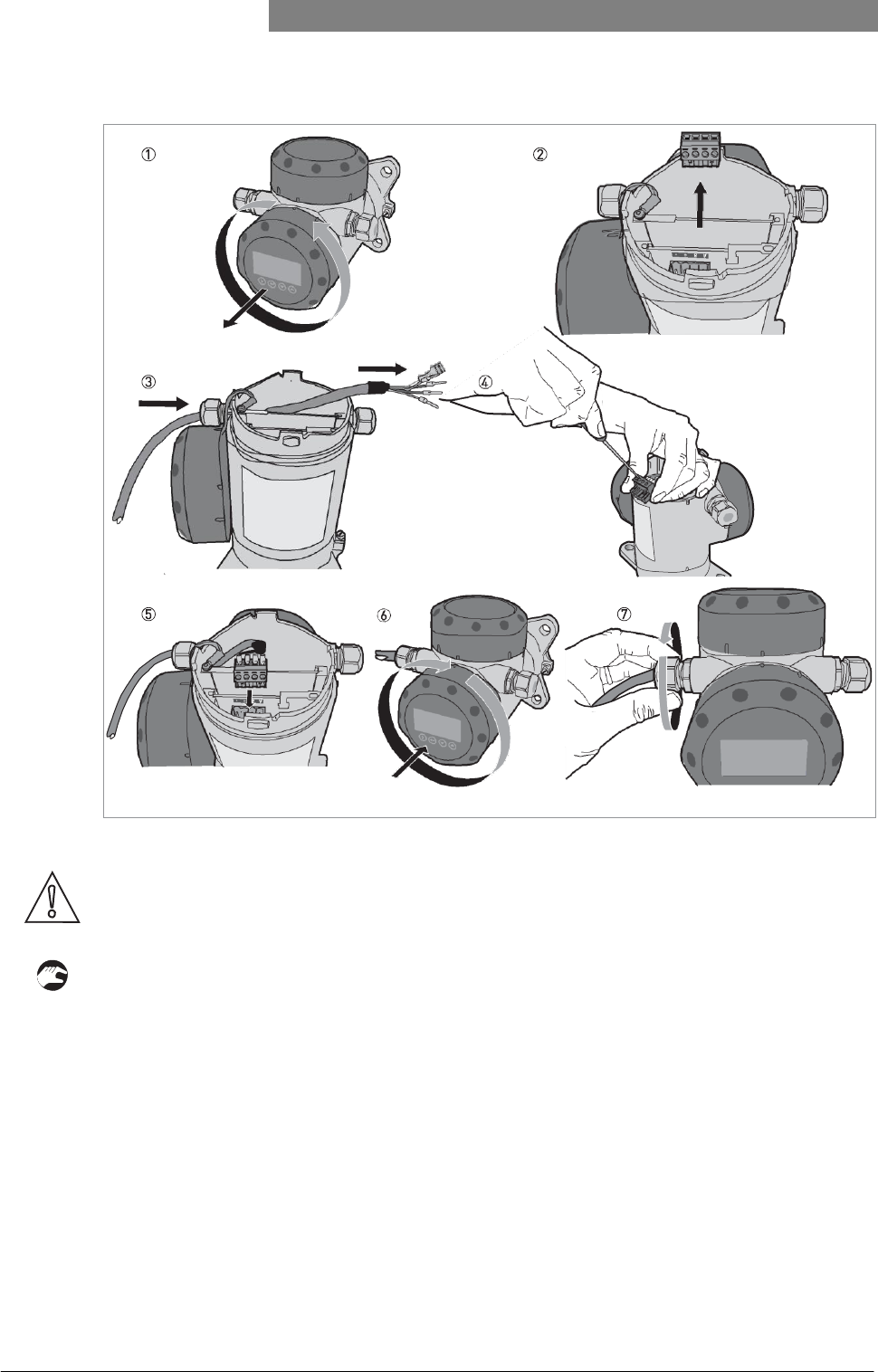
How to connect the communication cable to the remote converter
Figure 4-11: How to connect the communication cable to the remote converter
CAUTION!
Bending radius
of the
communication cable:
≥ 50
mm
/ 2¨
1 Remove the terminal compartment cover.
2 Remove the 4-pin connector.
3 Put the communication cable into the opening of the cable gland.
4 Put the electrical wires in the connector terminals. Tighten the terminal screws with a small slotted-tip screwdriver. Make sure
that the electrical wires agree with the terminals. For more data, refer to the electrical schema in this section.
5 Put the connector into the 4-pin socket. Attach the Faston connector (drain wire).
6 Attach the terminal compartment cover.
7 Tighten the cable gland. Make sure that the remote converter is correctly sealed.
03/2012 - 4001904901 - HB OPTIWAVE 5200 R01 en
www.krohne.com
37
OPTIWAVE 5200 C/F ELECTRICAL CONNECTIONS 4
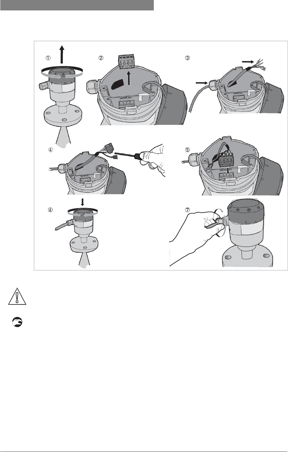
How to connect the communication cable to the antenna housing
Figure 4-12: How to connect the communication cable to the antenna housing
CAUTION!
Bending radius
of the
communication cable:
≥ 50
mm
/ 2¨
1 Remove the terminal compartment cover.
2 Remove the 4-pin connector.
3 Put the communication cable into the opening of the cable gland.
4 Put the electrical wires in the connector terminals. Tighten the terminal screws with a small slotted-tip screwdriver. Make sure
that the electrical wires agree with the terminals. For more data, refer to the electrical schema in this section.
5 Put the connector into the 4-pin socket. Attach the Faston connector (drain wire).
6 Attach the terminal compartment cover.
7 Tighten the cable gland. Make sure that the probe housing is correctly sealed.
38
www.krohne.com
03/2012 - 4001904901 - HB OPTIWAVE 5200 R01 en
4
ELECTRICAL
CONNECTIONS
OPTIWAVE 5200 C/F
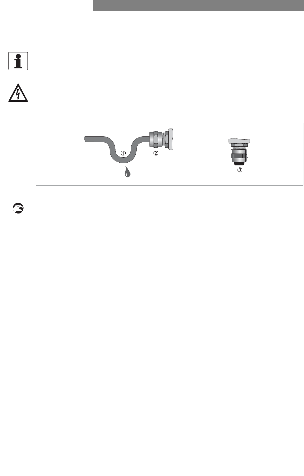
4.4 Protection category
INFORMATION!
The device fulfills
all
requirements per protection category
IP
66/67 (equivalent
to
NEMA type
4X
(housing) and type
6P (antenna)).
DANGER!
Make sure that
the
cable gland
is watertight.
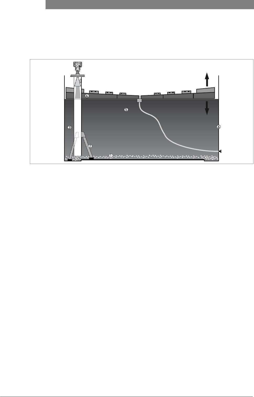
Figure 4-13: How to make the installation agree with protection category IP 67
• Make sure that the gaskets are not damaged.
• Make sure that the electrical cables are not damaged.
• Make sure that the electrical cables agree with the national electrical code.
• The cables are in a loop in front of the device 1 so water does not go into the housing.
• Tighten the cable feedthroughs 2.
• Close unused cable feedthroughs with dummy plugs 3.
03/2012 - 4001904901 - HB OPTIWAVE 5200 R01 en
www.krohne.com
39
OPTIWAVE 5200 C/F ELECTRICAL CONNECTIONS 4
4.5 Networks
4.5.1 General information
The device uses the HART® communication protocol. This protocol agrees with the HART® Communication Foundation standard. The
device can be connected point-to-point. It can also operate in a multi-drop network of up to 15 devices.
The device output is factory-set to communicate point-to-point. To change the communication mode from point-to-point to multi-
drop, refer to
Network configuration
on page 66.
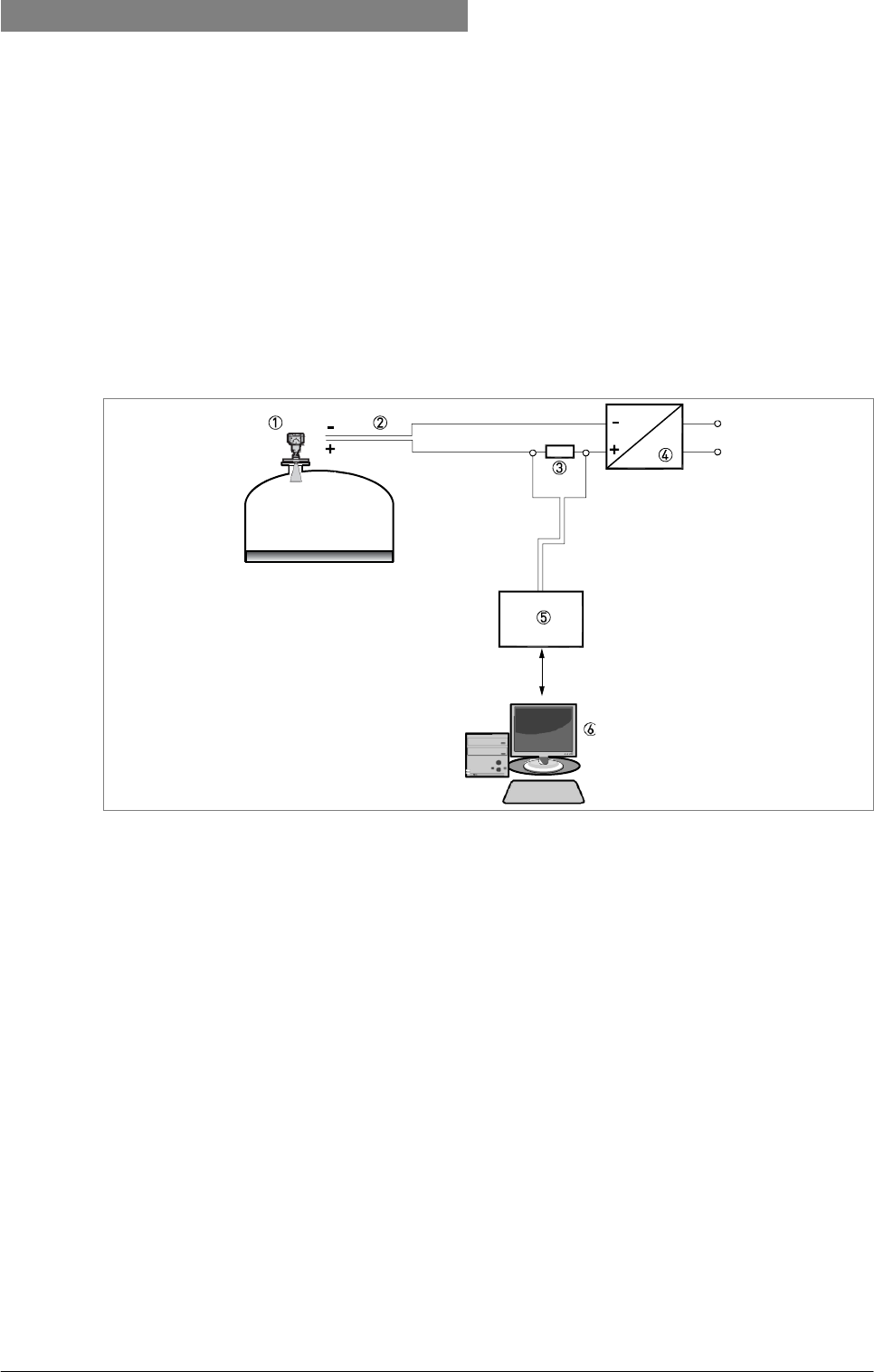
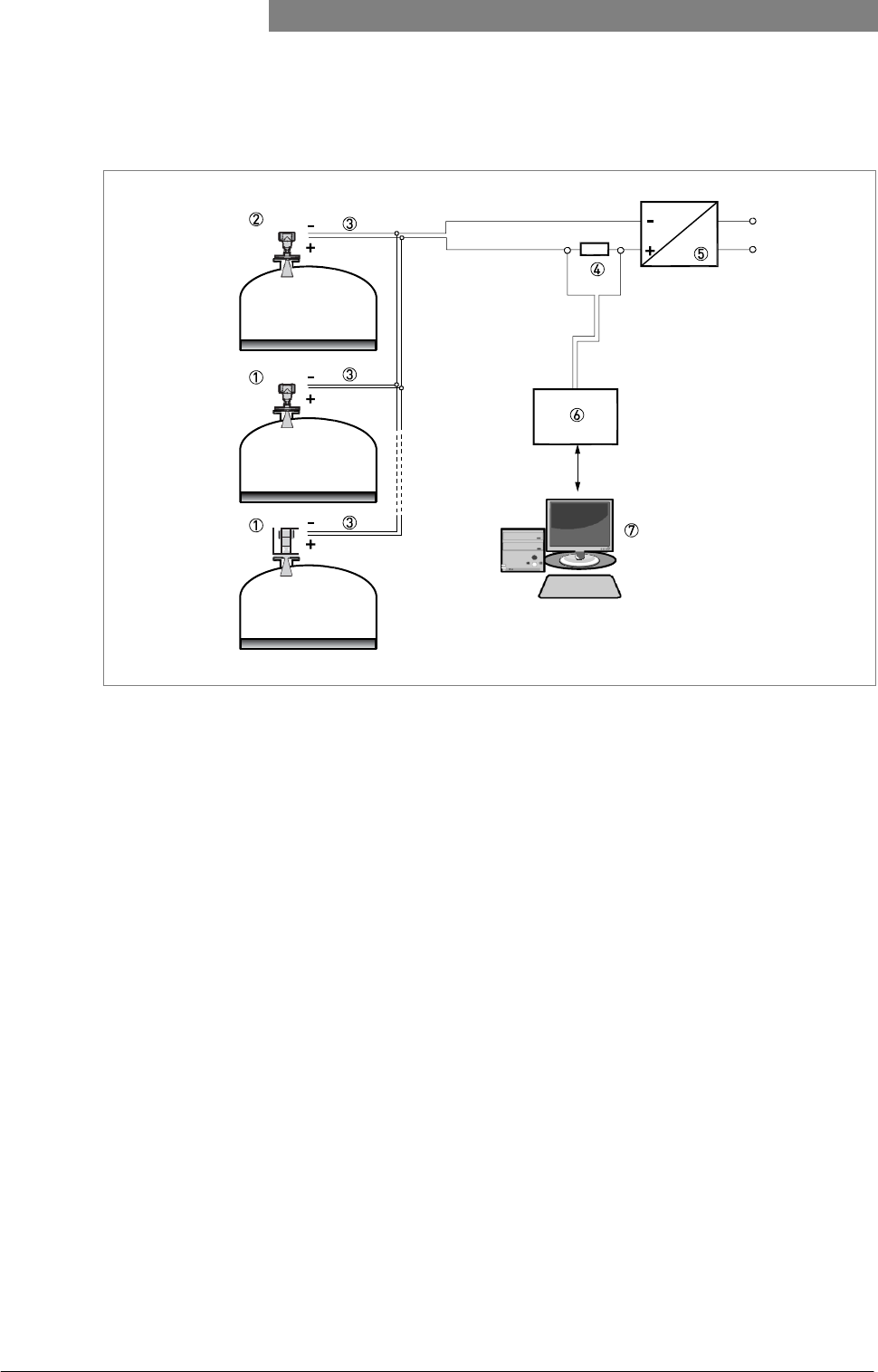
4.5.2 Point-to-point connection
Figure 4-14: Point-to-point connection (non-Ex)
1 Address of the device (0 for point-to-point connection)
2 4...20 mA +
HART
®
3 Resistor for HART® communication
4 Power supply
5 HART® converter
6 HART® communication software
40
www.krohne.com
03/2012 - 4001904901 - HB OPTIWAVE 5200 R01 en
4
ELECTRICAL
CONNECTIONS
OPTIWAVE 5200 C/F
4.5.3 Multi-drop networks
Figure 4-15: Multi-drop network (non-Ex)
1 Address of the device (n+1 for multidrop networks)
2 Address of the device (1 for multidrop networks)
3 4 mA +
HART
®
4 Resistor for HART® communication
5 Power supply
6 HART® converter
7 HART® communication software
03/2012 - 4001904901 - HB OPTIWAVE 5200 R01 en
www.krohne.com
41
OPTIWAVE 5200 C/F ELECTRICAL CONNECTIONS 4
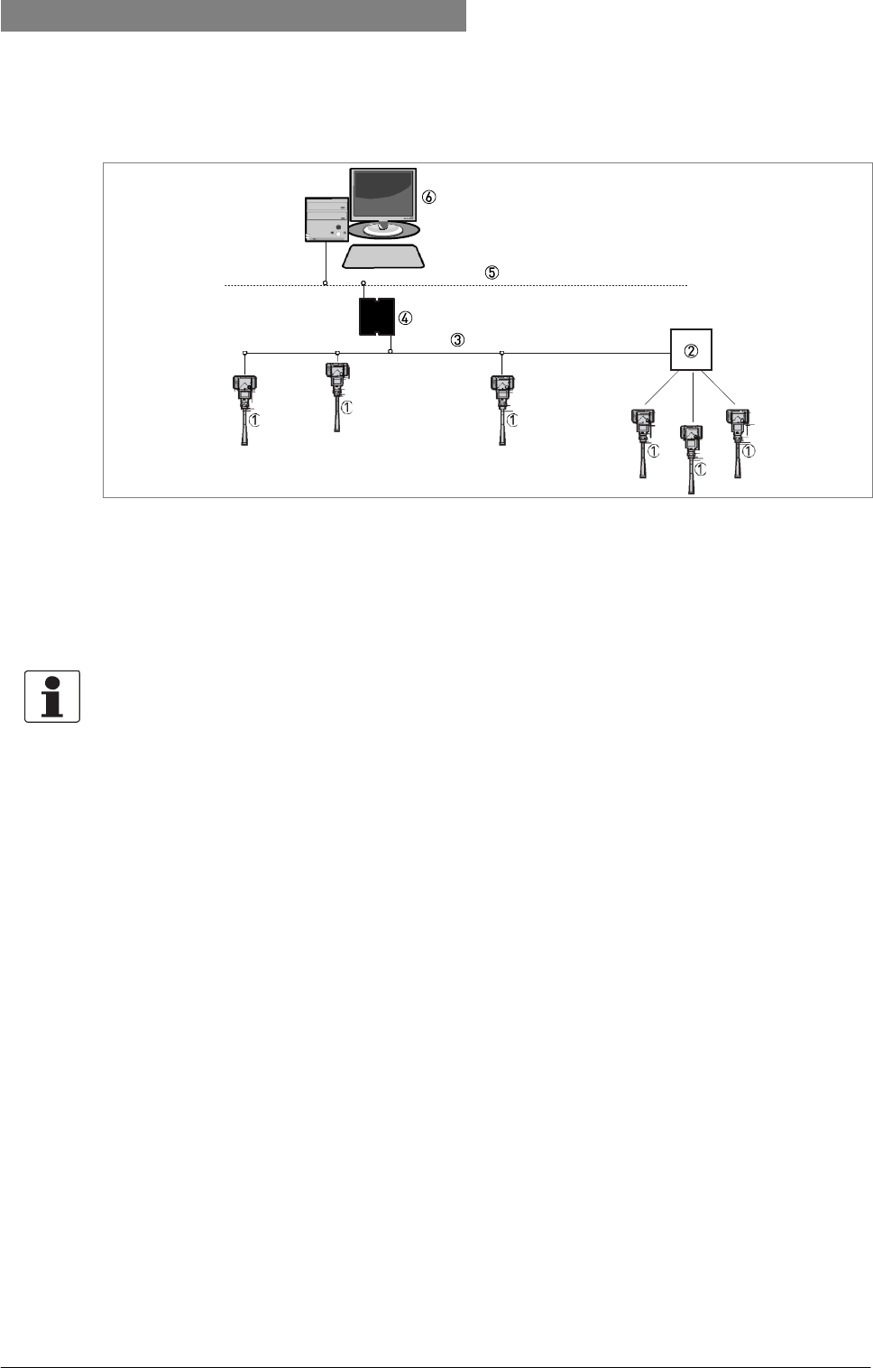
4.5.4 Fieldbus networks
FOUNDATION Fieldbus™ network (non-Ex)
Figure 4-16: FOUNDATION Fieldbus™ network (non-Ex)
1 Field device
2 Junction box
3 H1 network
4 H1/HSE converter
5 High Speed Ethernet (HSE)
6 Workstation
INFORMATION!
It is
necessary
to
have
a
separate power supply
to
energize devices with
the FOUNDATION™
Fieldbus output option (4-wire device with local HART
®
connection). The
FF
terminal
is
connected
to a
Fieldbus Power Hub. The
24
VDC
terminal energizes the device. The power
supply is not
shown
in the illustration.
42
www.krohne.com
03/2012 - 4001904901 - HB OPTIWAVE 5200 R01 en
4
ELECTRICAL
CONNECTIONS
OPTIWAVE 5200 C/F
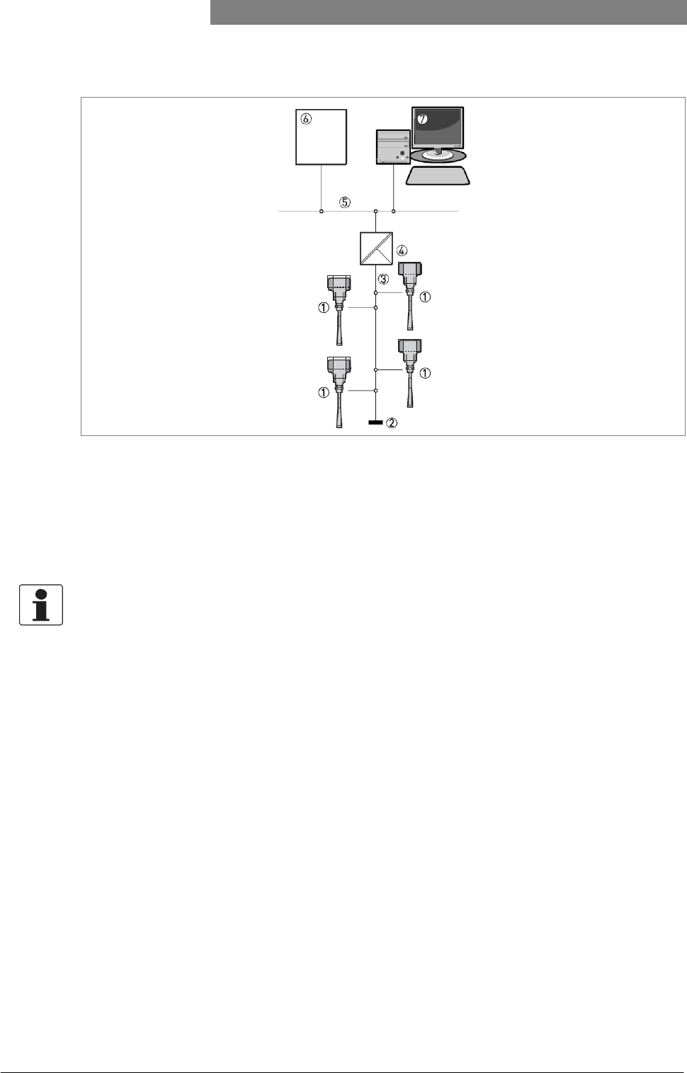
PROFIBUS PA/DP network (non-Ex)
Figure 4-17: PROFIBUS PA/DP network (non-Ex)
1 Field device
2 Bus termination
3 PROFIBUS PA bus segment
4 Segment coupler (PA/DP link)
5 PROFIBUS DP bus line
6 Control system (PLC / Class 1 master device)
7 Engineering or operator workstation (Control tool / Class 2 master device)
INFORMATION!
It is
necessary
to
have
a
separate power supply
to
energize devices with
the
PROFIBUS
PA
output option (4-wire device with local HART
®
connection). The PROFIBUS
PA
terminal
is
connected
to a
segment coupler. The
24
VDC
terminal energizes
the
device. The power supply
is not
shown
in the illustration.

03/2012 - 4001904901 - HB OPTIWAVE 5200 R01 en
www.krohne.com
43
OPTIWAVE 5200 C/F START-UP 5
5.1 How to start the device
5.1.1 Start-up checklist
Check these points before you energize the device:
• Are all the wetted components (antenna, flange and gaskets) resistant to the product in the tank?
• Does the information on the signal converter nameplate agree with the operating data?
• Did you correctly install the device on the tank?
• Do the electrical connections agree with the national electrical codes?
DANGER!
Before you energize
the
device, make sure that
the
supply voltage and polarity are
correct.
DANGER!
Make sure that the device and the installation agrees with
the
requirements
of the Ex certificate
of compliance.
5.1.2 How to start the device
• Connect the converter to the power supply.
• Energize the converter.
i
Devices with the LCD display option only: After 10 seconds the screen will display "Starting up". After 20 seconds the screen will
display the software version numbers. After 30 seconds the default screen will appear.
• The device will display readings.
5.2 Operating concept
You can read measurements and configure the device with:
• A digital display screen (optional).
• A connection to a system or PC with PACTware™. You can download the Device Type Manager (DTM) file from the internet site. It
is also supplied on the CD-ROM delivered with the device.
• A connection to a system or PC with AMS™. You can download the Device Description (DD)
file from the internet site. It is also supplied on the CD-ROM delivered with the
device.
• A connection to a HART® Handheld Communicator.
44
www.krohne.com
03/2012 - 4001904901 - HB OPTIWAVE 5200 R01 en
5
START-UP
OPTIWAVE 5200 C/F
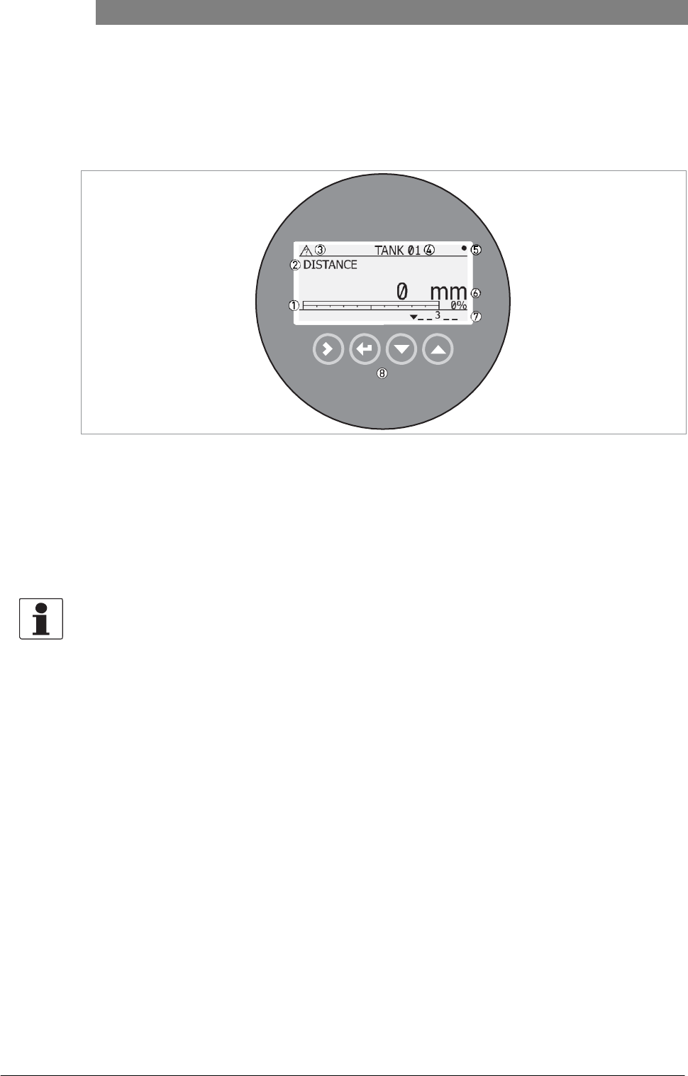
5.3 Digital display screen
5.3.1 Local display screen layout
Figure 5-1: Local display screen layout in Normal mode
1 Current output percentage (bar graph and text - only shown if the current output function is the same as the measure- ment on the screen in normal mode)
2 Measurement type (in this example, distance)
3 Device status (NE 107 symbols)
4 Device tag name
5 Updated measurement data symbol
6 Measurement value and units
7 Device status (markers)
8 Keypad buttons (refer to the table in the section that follows)
INFORMATION!
The current output percentage
is
only shown
for the
output function (set
in
menu item
2.4.1
OUTPUT FUNC.). For example,
if the
output function
is set to
"Level" and normal mode
displays
"Distance" measurements,
the bar
graph and text
is not shown.
03/2012 - 4001904901 - HB OPTIWAVE 5200 R01 en
www.krohne.com
45
OPTIWAVE 5200 C/F OPERATION 6
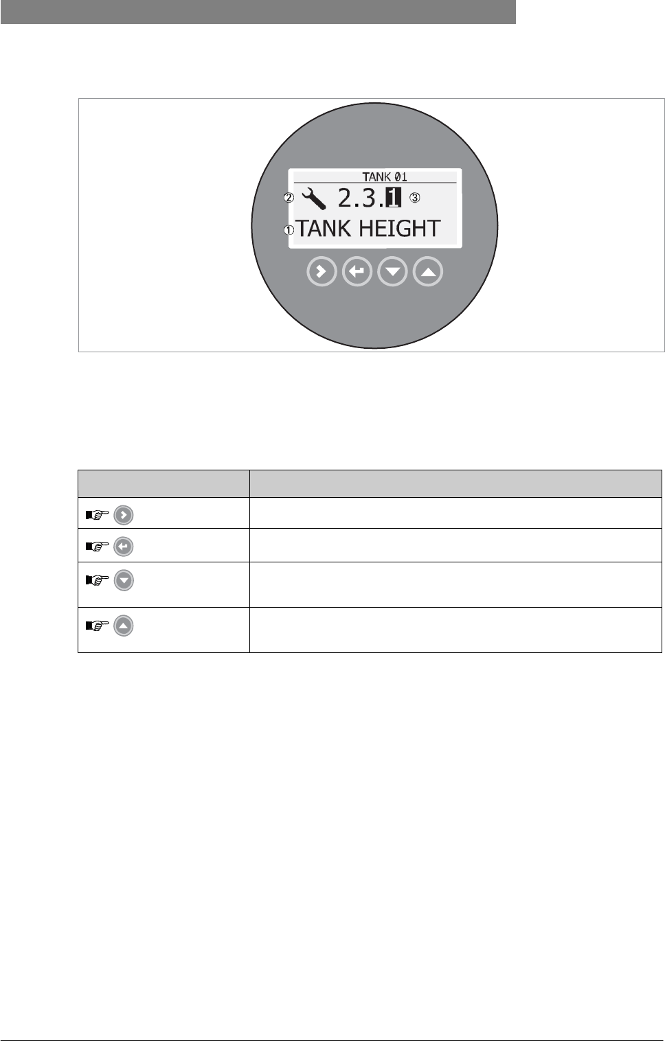
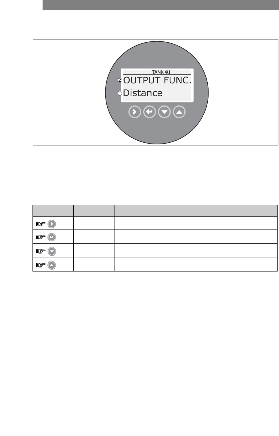
Figure 5-2: Local display screen layout in configuration mode
1 Function name
2 Configuration mode symbol
3 Menu number
5.3.2 Keypad buttons
Keypad button
Function
[Right]
Readings: Enter Commissioning menu (Enter Configuration mode)
[Return / Escape]
Readings: Change units (m, cm, mm, in, ft) Configuration
mode: Exit
[Down]
Readings: Change measurement type (distance, level , output (%), output (mA))
Configuration mode: Decrease value or change parameter
[Up]
Readings: Change measurement type (distance, level , output (%), output (mA))
Configuration mode: Increase value or change parameter
For data on keypad functions, refer to
Normal mode
on page 52.
46
www.krohne.com
03/2012 - 4001904901 - HB OPTIWAVE 5200 R01 en
6
OPERATION
OPTIWAVE 5200 C/F
6.1 User modes
Normal mode This mode displays measurement data. For more data, refer to Normal
mode
on page 52.
Configuration mode Use this mode to view parameters, commission the device, create tables for volume or mass
measurement, change critical values to measure in difficult process conditions. To get access to
supervisor menu, refer to
Protection
of
the device settings
on page 65. For more data on menu items,
refer to
Function description
on page 58.
6.2 Normal mode
This mode shows measurement data. Use the table that follows:
• for the selection of the measurement type (level, distance, percentage, conversion),
• for the selection of the measurement units and
Some measurement types will only be available if the device has the correct parameters entered in the configuration mode.
Keypad functions
Button
Description
Function
"Hot key" function
Right
Enter configuration mode.
-
Return /
Escape
Change the measurement units.
-
Down
Change the measurement type.
-
Up
Change the measurement type.
Display language will change to
English 1
Return and
Down
-
-
1 The display language will change when you press this button for 2 seconds. Press the button again and it will go back to the original language.

03/2012 - 4001904901 - HB OPTIWAVE 5200 R01 en
www.krohne.com
47
OPTIWAVE 5200 C/F OPERATION 6
Measurement type definitions
Measurement type
Description
Available units
LEVEL
This is a display and an output function option. It is
the height from the bottom of the tank to the surface
of the liquid (Tank height - Distance).
m, cm, mm, in (inches), ft
(feet)
DISTANCE
This is a display and an output function option.
It is the distance from the face of the flange to
the surface of the liquid.
m, cm, mm, in (inches), ft
(feet)
CONVERSION
This is a display and an output function option. It
gives the volume, mass or flow rate of the tank
contents. This data is available if you prepare a
volume, mass or flow rate table in configuration
mode. For
data on how to prepare the conversion table,
refer to
How
to
configure
the
device
to
measure
volume
or
mass
on page 68.
m3, L, gal (US gallons), ImpG (Imperial
gallons), ft3, bbl (oil barrel), kg, t, Ston,
Lton, m, cm, mm, in, ft, m3/h, ft3/h
ULLAGE CONV.
This is a display and an output function option. It
gives the empty volume or remaining mass that
can be put in the tank. This data is available if you
prepare a volume or mass table in configuration
mode. For data on how to prepare the conversion
table, refer to
How
to
configure
the
device
to
measure
volume
or
mass
on page 68.
m3, L, gal (US gallons), ImpG (Imperial
gallons), ft3, bbl (oil barrel), kg, t, Ston,
Lton, m, cm, mm, in, ft, m3/h, ft3/h
OUTPUT I (mA)
The current output of the device.
mA
OUTPUT I (%)
The percentage of the current output. 0% = 4
mA. 100% = 20 mA.
%
6.3 Configuration mode
6.3.1 General notes
Change the settings of your device in Configuration mode. Data about the menus is given on page
58. You can:
• Use the 1.0.0 INFORMATION menu to read settings, device software versions and error records. For more data about the
Information menu, refer to Table A. Info.
• Use the 2.0.0 SUPERVISOR menu run diagnostic tests, set up a conversion table for volume, mass or flow rate measurement,
change critical parameters for difficult process conditions, reset the device and change basic parameters (tank height etc.),
output settings, HART Address etc. For more data about the Supervisor menu, refer to Table 2. Supervisor.
INFORMATION!
It is not
possible
to
enter
the
3.0.0 SERVICE and 4.0.0 MASTER
menus.
These menus
are for
factory calibration and qualified service personnel
only.
48
www.krohne.com
03/2012 - 4001904901 - HB OPTIWAVE 5200 R01 en
6
OPERATION
OPTIWAVE 5200 C/F
6.3.2 How to get access to the commissioning menu
Do the steps that follow:
• Press the [>] button.
i
This shows the Information menu. The Information menu is read only and does not have password security.
• Press the [ ] button one time to scroll up to the Supervisor menu.
i
The screen shows the text "2.0.0 SUPERVISOR".
• Press the [>] button one time.
i
The screen shows a line. You must enter the password. Press the buttons under the display screen 6 times (in total and in a given
order) to to get access to Configuration mode.
• Type in the password. The factory-set password is [>],
[
^
],
[ ], [ ], [>] and
[
^
].
i
The device shows the text "2.1.0 COMMISSION.". Make a selection from the items in the supervisor menu.
CAUTION!
SIL-approved
devices:
For data about critical device parameters
for
SIL approval, refer
to the
Safety Manual
(SIL
approval).
INFORMATION!
How
to set the
supervisor password
to
"on"
or "off"
The supervisor password
is set to
"on"
by
default.
If it is
necessary
to set
this function
to "off",
refer
to
Function description
on
page
58, Table 2: Supervisor menu, menu item PSWD YES/NO
(2.7.4).
INFORMATION!
How
to
change the supervisor
password
You can change
the
password
for the
supervisor menu.
For
more data, refer
to Function
description
on
page
58, Table 2: Supervisor menu, menu item PASSWORD (2.7.5).
03/2012 - 4001904901 - HB OPTIWAVE 5200 R01 en
www.krohne.com
49
OPTIWAVE 5200 C/F OPERATION 6
6.3.3 Keypad functions
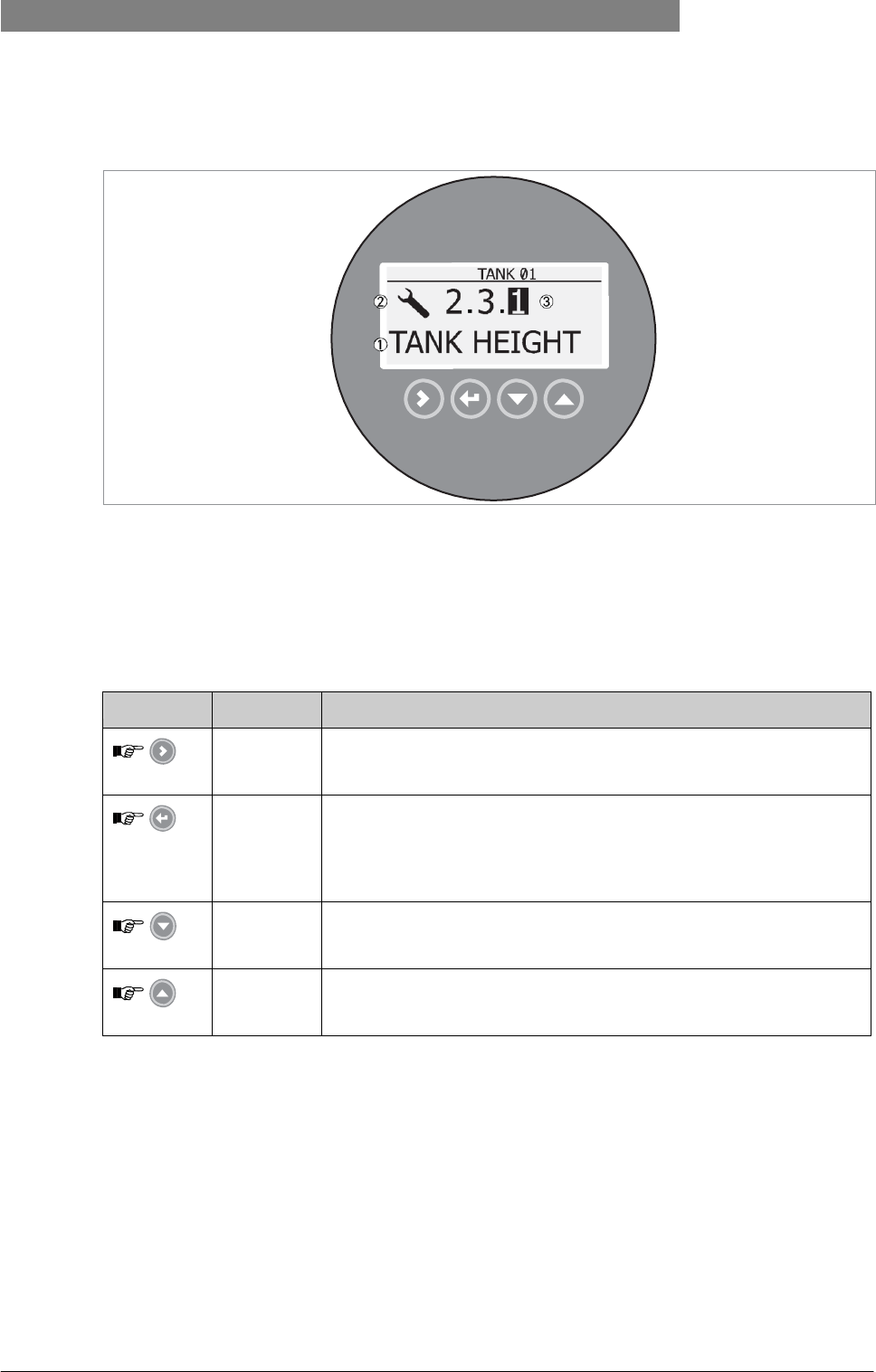
Figure 6-1: Local display screen layout in configuration mode
1 Function name
2 Configuration mode symbol
3 Menu number
This is what you see when you are in Configuration mode. The functions of the buttons are given in the table that follows:
Functions of buttons for menu navigation
Button
Description
Function
Right
• Go down to the sub-menu level (for example, from menu 1.0.0 to sub- menu 1.1.0).
• Enter the menu item
Enter /
Esc (Escape)
• Go up to the menu level (for example, from sub-menu 1.1.0 to menu
1.0.0).
• Go to Normal mode. If you changed settings in Configuration mode, you must save or cancel your new
settings. For more data, refer to the end of this section.
Down
• Scroll down the menu list (for example, from menu 2.0.0 to menu 1.0.0).
• Scroll down the sub-menu list (for example, from sub-menu 2.2.0 to sub-
menu 2.1.0).
Up
• Scroll up the menu list (for example, from menu 1.0.0 to menu 2.0.0).
• Scroll up the sub-menu list (for example, from sub-menu 2.1.0 to sub-
menu 2.2.0).
50
www.krohne.com
03/2012 - 4001904901 - HB OPTIWAVE 5200 R01 en
6
OPERATION
OPTIWAVE 5200 C/F
Lists of parameters in menu items
Figure 6-2: Lists of parameters in menu items
1 Parameter
2 Menu name
This is what you see when you select a menu item that has a list of parameters. The functions of the buttons are given in the table that
follows:
Function of buttons in menu items that have a list of parameters
Button
Description
Function
Right
n/a
Enter /
Esc (Escape)
Select the parameter and go back to the menu
Down
Move down the list
Up
Move up the list
03/2012 - 4001904901 - HB OPTIWAVE 5200 R01 en
www.krohne.com
51
OPTIWAVE 5200 C/F OPERATION 6
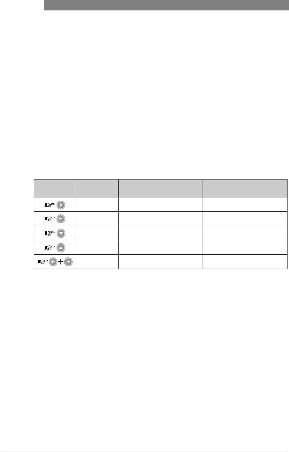
Values in menu items
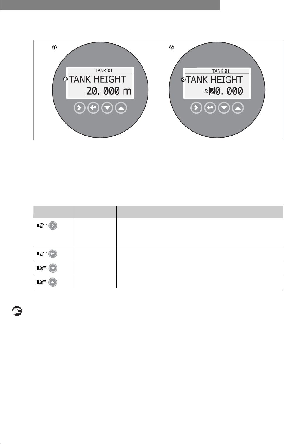
Figure 6-3: Values in menu items
1 Menu item with values stored at this time (first screen)
2 Press [>] again to change the values. A cursor shows on the first digit.
3 Menu item name
4 Cursor on the selected digit
This is what you see when you select a menu item that has a value. The functions of the buttons are given in the table that follows:
Function of buttons in menu items that have values
Button
Description
Function
Right
• Enter the menu item and see the value stored at this time.
• Enter the menu item configuration level to change the value.
• Move the cursor to the next digit on the right. If the cursor is on the
last digit, press [>] again to go back to the first digit.
Enter /
Esc (Escape)
Accept the value and go back to the sub-menu.
Down
Decrease the digit value.
Up
Increase the digit value.
How to save settings changed in the supervisor menu (menu 2.0.0)
• When you have changed parameters in all the necessary menu items, press
[
^
]
to accept the new parameter.
• Press
[
^
]
to go back to the "STORE" screen.
• The device will ask you to save or cancel your settings. Press [ ] or [ ] to select STORE YES
or STORE NO. Press
[
^
]
to accept or reject the new settings.
i
The display goes back to Normal mode.
52
www.krohne.com
03/2012 - 4001904901 - HB OPTIWAVE 5200 R01 en
6
OPERATION
OPTIWAVE 5200 C/F
6.3.4 Menu overview
1.0.0 Info. (Information)
1.1.0
Ident. (Identification)
1.2.0
Output
1.3.0
History
2.0.0 Supervisor
2.1.0
Commissioning
2.2.0
Tests
2.3.0
Basic Parameters
2.4.0
Output I
2.5.0
Application
2.6.0
Communication
2.7.0
Display
2.8.0
Conversion
2.9.0
Config/Reset
3.0.0 Service
n/a Password locked. Menus for factory calibration and qualified service personnel only.
4.0.0 Master
n/a Password locked. Menus for factory calibration and qualified service personnel only.
6.3.5 Function description
1. Information (Info.) menu
Menu
No.
Function
Function description
Selection list
Default
1.0.0
INFORMATION
A summary of information relating to
the device.
1.1.0
IDENT.
1.1.1
SERIAL NUM.
The device serial number.
Read only.
1.1.2
CONV.FIRM.VER
The converter firmware version.
Read only.
1.1.3
SEN.FIRM.VER
The sensor firmware version.
Read only.
1.1.4
HMI.FIRM.VER
The HMI (device display screen)
firmware version.
Read only.
1.2.0
OUTPUT I
1.2.1
SUMMARY I
This shows the settings at this time for the
output function (OUTPUT FUNC.), output
range (RANGE I), 4 mA setting (SCALE
4mA), 20 mA setting (SCALE
20mA), and error delay (ERROR
DELAY).
Read only.

03/2012 - 4001904901 - HB OPTIWAVE 5200 R01 en
www.krohne.com
53
OPTIWAVE 5200 C/F OPERATION 6
Menu
No.
Function
Function description
Selection list
Default
1.3.0
HISTORY
1.3.1
ERROR RECORD
A log of device errors. Press [>] to read the
errors. Press [ ] or [ ] to scroll up or
down the
list. Each error is identified by a code.
Press > again to show the number of
incidents and the time since the last
incident in days, hours, minutes and
seconds. For more data on errors,.
Read only.
2. Supervisor menu
Menu
No.
Function
Function description
Selection list
Default
2.0.0
SUPERVISOR
The supervisor can use this menu to
change parameters.
2.1.0
COMMISSION.
2.1.1
PARAMETERS
This starts a quick set-up procedure
applicable to most applications. The
supervisor can give the tank height (TANK
HEIGHT), type of tank (TANK TYPE), output
function (OUTPU FUNC.), current output
range (RANGE I), 4 mA setting (SCALE
4mA), 20 mA setting (SCALE
20mA), error delay (ERROR
DELAY) and tag name (TAG
NAME).
2.1.2
EMP.SPEC.REC.
Fixed and moving objects in the tank cause
interference
signals. Put them through this filter to
correctly measure the tank contents. A
quick set-up procedure will go through the
steps that follow:
1
Do you have a completely filled tank?
If the tank is full, it is not possible to
complete this procedure. The tank must
be partially filled or empty.
Yes [>], No [ ]
2
Please, activate moving parts! We
recommend that you switch on moving
equipment to filter all interference signals.
OK [>]
3
IIs your tank partially filled or empty?
If the tank is partially filled, the device must
include the tank contents when it filters the
signal.
Partially [>], Empty [ ]
4
MEAS.DISTANCE
If the tank is partially filled,
type in a distance shorter than
that between the flange and the
tank contents.
min-max:
0…tank height (2.3.1)
?

54
www.krohne.com
03/2012 - 4001904901 - HB OPTIWAVE 5200 R01 en
6
OPERATION
OPTIWAVE 5200 C/F
Menu
No.
Function
Function description
Selection list
Default
5
Emp.Spec.Type
Use the average value for tanks
which contain fixed objects
only. Use the maximum value
for tanks which contain many
objects or moving objects.
Maximum, Average
?
6
Recording in progress
Reading in progress
7
Empty spectrum graph
Push [>] to make a selection
from the available spectra to
get the correct level signal, if
the tank is partially filled.
8
Do you want to save the
spectrum?
Yes [>], No [ ]
2.2.0
TESTS
The device serial number.
2.2.1
SET OUTPUT
This sets the current output to a test value
[mA]. The output will change to the given
value, independent of the measured value.
The current output will go back to the
measured value when the display goes back
to the menu level.
3.5, 4, 6, 8, 10, 12, 14, 16,
18, 20 or 22 mA
3.5 mA
2.2.2
DIAGNOSTIC
This starts the hardware test. Press [>]
many times to show: the time of operation
(D1), temperature of the electronic
converter board (T1), loop current (I1), load
current (I2), voltage 5.6 V (V1), voltage on
capacitors (V2), voltage 3.3 V (V3), reset
counter (C1). If you press [>] again, the
display goes back to the menu level.
2.3.0
BASIC PARAM.
The basic parameters for
configuration of the device.
2.3.1
TANK HEIGHT
The distance from the flange face /
thread stop of the tank connection down
to the tank bottom.
min-max:
0…30 m / 0…98.4 ft
10.0 m /
32.8 ft
2.3.2
BLOCK. DIST.
Blocking distance. The distance from the
flange to the top limit of the measuring
range (a zone given by the user where it is
not possible to measure). We recommend a
blocking
distance of 500 mm / 19.7¨ below the
antenna. If the distance is less than the
blocking distance, the device continues
to display the blocking distance.
min: 100 mm / 13.9¨ or
2.3.6 ANTENNA.EXT
max: 2.3.1 TANK HEIGHT
500 mm /
19.7¨
2.3.3
TIME CONST.
Using this function, the device processes
several measurement readings to filter out
disturbances. Increasing the time constant
will
smoothen the integrated readings,
decreasing will roughen the
readings. s=seconds.
min-max:
1.00...100.00 s
10.00 s

03/2012 - 4001904901 - HB OPTIWAVE 5200 R01 en
www.krohne.com
55
OPTIWAVE 5200 C/F OPERATION 6
Menu
No.
Function
Function description
Selection list
Default
2.3.4
STILLWELL EN.
If the device is installed in a stilling well
or has a Wave- Guide antenna, set this
menu item to "Yes".
YES, NO
NO
2.3.5
STILLWELL D.
The inner diameter of the stilling well. If the
device is installed in a stilling well or has a
Wave-Guide antenna, enter the diameter.
The device will use this data if you set 2.3.4
STILLWELL EN. to "Yes". This menu item is
not shown if you set 2.3.4 STILLWELL EN. to
"No".
min-max:
22...999 mm / 0.9...39.3¨
100 mm /
3.9¨
2.3.6
STILLWELL H.
The height of the stilling well. If the device is
installed in a stilling well or has a Wave-
Guide antenna, enter the height. The device
will use this data if you set 2.3.4 STILLWELL
EN. to "Yes". This menu item is not shown if
you set 2.3.4
STILLWELL EN. to "No".
min: 500 mm / 19.7¨
max: 2.3.1 TANK HEIGHT
10000 mm /
393.7¨
2.3.7
ANTENNA.EXT
Optional antenna extensions.These are
attached between the flange and the
antenna.
min: 0 mm / 0¨ or 2.3.6
ANTENNA.EXT
max: 2000 mm / 78.7¨ or
2.3.1 TANK HEIGHT
0 mm / 0¨
2.3.8
ANTENNA.TYP
Type of antenna. For more data, refer to
Technical data
on page
79.
PP Horn, PTFE Horn, Metal. Horn,
Wave Stick, Wave Guide
PP Horn
2.3.9
DIST.PIECE
Optional distance piece between the
converter and the process connection. This
is for high-temperature applications more
than +150°C / +302°F. The distance piece is
120 mm / 4.7¨ long. For more data, refer to
Technical data
on page 79.
min: 0 mm / 0¨
max: TANK HEIGHT
0 mm / 0¨
2.3.10
TAG NAME
The device has a code (tag name) to
identify it. The supervisor can enter a
maxmimum of 8 numbers or letters.
?
TANK 01
2.4.0
OUTPUT I
Use this sub-menu to give
measurement values to the current
output.
2.4.1
OUTPUT FUNC.
The output function. Select an output
function to scale the current values in
relation to a given point (usually the device
process connection or the tank bottom). The
output current value is shown on a bar
graph in normal mode if the measurement
name is the same as the output function.
Conversion parameters are shown if there
is volume, mass or flow rate data in 2.8.1
INPUT TABLE.
Distance, Level,
Conversion, Ullage
conversion
Distance

56
www.krohne.com
03/2012 - 4001904901 - HB OPTIWAVE 5200 R01 en
6
OPERATION
OPTIWAVE 5200 C/F
Menu
No.
Function
Function description
Selection list
Default
2.4.2
RANGE I
This parameter sets the range of the
output current with (3.8...20.5 mA) or
without (4...20 mA) over-run values. It
also tells the device what to do if an error
occurs. For example, the device will change
to an error value of 22 mA if you set
RANGE I to 4-20/22E. If you set RANGE I to
4-20 and the device senses a measurement
error, the value will stop at the last correct
measurement.
4-20, 4-20/22E, 4-20/3.6E,
3.8-20.5/22E,
3.8-20.5/3.6E
4-20/3.6E
1
2.4.3
SCALE 4mA
This gives a measurement value to 4
mA.
min.-max: 2
1m/ 3.28 ft
2.4.4
SCALE 20mA
This gives a measurement value to 20
mA.
min.-max: 3
45 m /
147.63 ft
2.4.5
ERROR DELAY
The time after which the current output
changes to an error value. The error
value shows that there is a measurement
error. mn=minutes and s=seconds.
0 s, 10 s, 20 s, 30 s, 1 mn,
2 mn, 5 mn,15 mn
1 mn
2.5.0
APPLICATION
Use this sub-menu to configure the device
when there are difficult process conditions.
Only approved personnel can change these
parameters.
2.5.1
TANK TYPE
The conditions in which the device is used. If
the surface of the product is flat, select
"Storage". If the surface of the product is
disturbed, select "Process". If the surface
of the product is agitated with vortexes and
foam, select "Agitator".
Storage, Process, Agitator
Process
2.5.2
TRACKING VEL.
Maximum tracking velocity. This value must
agree with the maximum rate of change of
the level of the liquid or solid contents in
the tank.
min-max:
0.1…10.0 m/min
1.0 m/min
4
2.5.3
Er PRODUCT
The device automatically calculates the
level based on the product εr. If you
select "TBF Partial" or "TBF Full" in menu
item 2.3.9
MEASUR.MODE, you can change the εr
value manually
to adjust readings.
min-max: 1.100 to 10.000
2.000

03/2012 - 4001904901 - HB OPTIWAVE 5200 R01 en
www.krohne.com
57
OPTIWAVE 5200 C/F OPERATION 6
Menu
No.
Function
Function description
Selection list
Default
2.5.4
MEASUR.MODE
The device uses the dielectric constant (εr)
of the tank contents to monitor level. In
direct mode (if the dielectric constant is
high), the level signal is a reflection on the
surface of the tank contents. If the
dielectric constant is low, the device uses
TBF mode. The device in TBF mode uses the
radar reflection on the bottom of the tank
(the signal goes through the tank contents).
This menu item is set by default to "Direct"
for tank contents with an εr >1.8. If εr is
very low (<1.6), use "TBF Full". If εr is
low (εr = 1.5...1.7), use "TBF Partial" mode.
"TBF Partial" is an automatic mode that lets
the device make a selection between "Direct
mode and "TBF" mode. If you use "TBF Full"
or "TBF Partial", enter the dielectric
constant in menu item 2.5.3 Er PRODUCT.
Refer also to "Measuring principle"
on page 79.
Direct, TBF Partial, TBF Full
Direct
2.5.5
OVERF. ENAB.
If this function is switched on, the device will
monitor the level even if it is in the blocking
distance. The displayed output stays fixed at
the blocking distance. An error is recorded
by default.
YES, NO
NO
2.5.6
MULT.REF.EN.
Multiple reflections will cause the device to
display smaller readings. Objects in the tank,
sharp corners, installation of the device on a
large nozzle or at the centre of a dome roof
can cause multiple reflections. A very calm
surface or a tank with a small convex or flat
roof can also cause multiple reflections.
YES, NO
NO
2.5.7
EMP.SPEC.EN.
The supervisor can start or stop the empty
spectrum filter.
YES, NO
NO
2.6.0
SERIAL I/O
Menu items for communication in field
networks.
2.6.1
ADDRESS
Any HART® address greater than 0 will
activate HART® multidrop mode. The
current output stays constant at 4 mA.
min.-max: 0…63
0
2.7.0
DISPLAY
This sub-menu includes all the display
parameters and password security
parameters for the supervisor menu.
2.7.1
LANGUAGE
Data can be shown in any of the languages
stored in the device. The standar language
is given in the customer order.
English, German, French, Italian,
Spanish, Portuguese, Japanese,
Chinese (Mandarin) and Russian
English

58
www.krohne.com
03/2012 - 4001904901 - HB OPTIWAVE 5200 R01 en
6
OPERATION
OPTIWAVE 5200 C/F
Menu
No.
Function
Function description
Selection list
Default
2.7.2
LENGTH UNIT
The length unit shown in normal
mode.
m, cm, mm, in (inches), ft
(feet)
m
2.7.3
CONV UNIT
Conversion unit. The length, volume, mass
or flow rate conversion unit for the
conversion table and shown in normal
mode.
m3, L, gal (US gallons), ImpG
(Imperial gallons), ft3, bbl (oil
barrel), kg, t, Ston, Lton, m, cm, mm,
in, ft, m3/h, ft3/h
L
2.7.4
PSWD YES/NO
If it is necessary to protect your settings in
the supervisor menu with a password, set
this menu item to "YES".
YES, NO
YES
2.7.5
PASSWORD
This changes the password for the
supervisor menu. Press the buttons up to 6
times in any order. This will be the new
password. To confirm the change, enter the
new password a second time.
[>], [
^
],
[ ], [ ],
[>] and [
^
]
2.7.6
CONTRAST
The contrast control for the display screen.
You can select a shade of grey between light
grey (level 20) and black (level
54).
min.-max: 20…54
36
2.8.0
CONV. TABLE
Conversion table. Use these menu items to
set up or erase conversion tables to show
length, volume or mass measurement values
in normal mode.
2.8.1
INPUT TABLE
The device uses the conversion table to
convert measurements to volume, mass and
flow rate readings. The readings are shown
in normal mode. Give
the number of entries on the table. Enter
the height and the related volume / mass /
flow
rate values.
max. 30 entries
(distance / volume, mass
or flow rate)
0 entries 5
2.8.2
DELETE TABLE
This menu item erases the data in the
conversion table.
YES, NO
NO
2.9.0
CONFIG/RESET
Use this sub-menu to start the device
again.
2.9.1
SAVE
This menu item is not available.
YES, NO
NO
2.9.2
RECALL
This menu item is not available.
YES, NO
NO
2.9.3
RESTART
This menu item starts the device
again.
YES, NO
NO
1 "4-20/3.6E" is necessary for SIL 2 approval. If you make a different selection, the device does not have SIL 2 approval.
2 Units and range depend on the output function, length unit and volume unit selected. See also the table of data depen- dencies for the 4 mA settings in this section.
3 Units and range depend on the output function, length unit and volume unit selected. See also the table of data depen- dencies for the 20 mA settings in this section.
4 1.0 m/min is necessary for SIL 2 approval. If you make a different selection, the device does not have SIL 2 approval.
5 0 entries is necessary for SIL 2 approval. If you make a different selection, the device does not have SIL 2 approval.
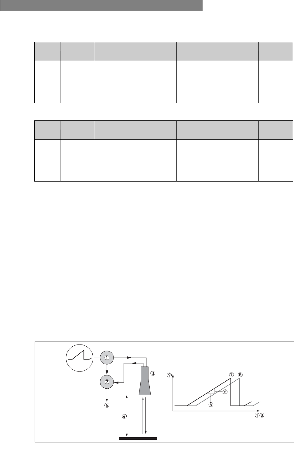
03/2012 - 4001904901 - HB OPTIWAVE 5200 R01 en
www.krohne.com
59
OPTIWAVE 5200 C/F TECHNICAL DATA 8
3. Service menu
Menu
No.
Function
Function description
Selection list
Default
3.0.0
SERVICE
Advanced settings. The settings in this menu
are protected with a password. Only
approved personnel can change the
parameters in this menu. For more data,
contact your local sales office.
4. Master menu
Menu
No.
Function
Function description
Selection list
Default
4.0.0
MASTER
Factory settings. The settings
in this menu are protected with
a password. Only approved
personnel can change the
parameters in this menu. For
more data, contact your local
sales office.
8.1 Measuring
principle
A radar signal is emitted via an antenna, reflected from the product surface and received after a time t. The radar principle used is
FMCW (Frequency Modulated Continuous Wave).
The FMCW-radar transmits a high frequency signal whose frequency increases linearly during the measurement phase (called the
frequency sweep). The signal is emitted, reflected on the measuring surface and received with a time delay, t. Delay time, t=2d/c,
where d is the distance to the product surface and c is the speed of light in the gas above the product.
For further signal processing the difference Δf is calculated from the actual transmit frequency and the receive frequency. The
difference is directly proportional to the distance. A large frequency difference corresponds to a large distance and vice versa. The
frequency difference Δf is transformed via a Fourier transformation (FFT) into a frequency spectrum and then the distance is
calculated from the spectrum. The level results from the difference between tank height and measuring distance.
Figure 8-1: Measuring principle of FMCW radar
1 Transmitter
2 Mixer
3 Antenna
4 Distance to product surface, where change in frequency is proportional to distance

60
www.krohne.com
03/2012 - 4001904901 - HB OPTIWAVE 5200 R01 en
8
TECHNICAL
DATA
OPTIWAVE 5200 C/F
5 Differential time delay, Δt
6 Differential frequency, Δf
7 Frequency transmitted
8 Frequency received
9 Frequency
10 Time

03/2012 - 4001904901 - HB OPTIWAVE 5200 R01 en
www.krohne.com
61
OPTIWAVE 5200 C/F TECHNICAL DATA 8
Measurement modes
"Direct" mode
If the dielectric constant of the tank contents is high (εr >1.8), the level signal is a reflection on the surface of the tank contents.
"Full TBF" mode
TBF = Tank Bottom Following. If the dielectric constant of the tank contents is very low (εr <1.6), you must use "Full TBF" mode to
measure level correctly. The device uses the radar reflection on the bottom of the tank (the signal goes through the tank contents).
"TBF Partial" mode
If the dielectric constant of the tank contents is low (εr =1.5...1.7), you must use "TBF Partial" mode to measure level correctly. TBF
Partial" is an automatic mode that lets the device make a selection between "Direct mode and "TBF" mode. If the device finds a large
radar reflection above the "tank bottom area" (the bottom 20% of the tank height), the device will use "Direct" mode. If the device finds
a large radar reflection in the "tank bottom area", the device uses TBF mode.
CAUTION!
"Full TBF" and "TBF Partial"
modes
It is
important
to
enter the correct dielectric constant value
in
menu item 2.5.3
Er
Product.
If not,
the
device will
not
measure level
accurately.
62
www.krohne.com
03/2012 - 4001904901 - HB OPTIWAVE 5200 R01 en
8
TECHNICAL
DATA
OPTIWAVE 5200 C/F
8.2 Technical data
INFORMATION!
•
The following data
is
provided
for
general applications.
If
you require data that
is more
relevant
to
your specific application, please contact
us or
your local representative.
•
Additional information (certificates, special tools, software,...) and complete
product
documentation can
be
downloaded free
of
charge from
the
website (Download
Center).
Measuring system
Measuring principle
2-wire loop-powered level transmitter; X-band (8.6...10.4 GHz) FMCW radar
Application range
Level measurement of liquids, pastes and slurries
Primary measured value
Distance
Secondary measured value
Level, volume, mass, flow rate and reflectivity
Design
Construction
The measurement system consists of a measuring sensor (antenna) and a signal converter
Options
Integrated LCD display (-20..+60°C / -4…+140°F); if the ambient temperature is not in these limits, the display
switches off automatically
Distance piece (for process temperatures more than +150°C / +302°F)
Straight antenna extensions
Max. extension length, PTFE Wave Horn antenna: 300 mm / 11.8¨;
Max. extension length, Metallic Horn antenna: 1000 mm / 39.4¨
S-bend antenna extension
- only for DN150 and DN200 Metallic Horn antenna options
90° bend antenna extension
- only for DN150 and DN200 Metallic Horn antenna options
Communication cable for remote housing version (refer to cable properties in
"Electrical connection: Remote device version")
Weather protection
Max. measuring range
PTFE and PP Wave Horn antennas and DN150 / DN200 Metallic Horn antennas:
30 m / 98.4 ft
DN80 / DN100 Metallic Horn antennas (installation only in stilling wells):
10 m / 32.8 ft
Wave Guide antenna:
6m/ 32.8 ft
Also depends on the dielectric constant of the product and the installation type. Refer also to "Antenna
selection".
Min. tank height
1m/ 3.3 ft
Dead zone
Antenna extension length + antenna length + 0.5 m / 19.7¨
Beam angle of antenna
PP Wave Horn: 10°
PTFE Wave Horn: 10°
Metallic Horn DN80 / 3¨: n/a - used only in stilling wells
Metallic Horn DN100 / 4¨: n/a - used only in stilling wells
Metallic Horn DN150 / 6¨: 8°
Metallic Horn DN200 / 8¨: 6°
Wave-Guide / stilling well: n/a - the radar signal is inside the tube.

03/2012 - 4001904901 - HB OPTIWAVE 5200 R01 en
www.krohne.com
63
OPTIWAVE 5200 C/F TECHNICAL DATA 8
Display and user interface
Display
LCD display
128 × 64 pixels in 8-step greyscale with 4-button keypad
Interface languages
3 language pack options (the language is given the customer order):
1 English, French German and Italian
2 English, French,Spanish and Portuguese
3 English, Chinese (Mandarin), Japanese and Russian
Measuring accuracy
Resolution
1 mm / 0.04¨
Repeatability
±1 mm / ±0.04¨
Accuracy
Standard: ±10 mm / ±0.4¨, when distance < 10 m / 33 ft; ±0.1% of measured distance, when distance >
10 m / 33 ft
Option: ±5 mm / ±0.2¨, when distance < 10 m / 33 ft; ±0.05% of measured distance, when distance > 10m/ 33 ft
Function of temperature
Reference conditions acc. to EN 61298-1
Temperature
+18...+30°C / 64.4...86°F
Pressure
1013 mbara ±50 mbar / 14.69 psia ±0.73 psi
Relative air humidity
60% ±15%
Target
Metal plate or trihedron in an anechoic chamber
Operating conditions
Temperature
Ambient temperature
-40…+80°C / -40…+176°F
Ex: see supplementary operating instructions or approval certificates
Storage temperature
-40…+80°C / -40…+176°F
Process connection temperature
PP Wave Horn antenna:
-20...+100°C / -4...+212°F
PTFE Wave Horn antenna:
-50...+150°C / -58...+302°F
Metallic Horn antenna / Wave Guide antenna: Standard: -
50…+130°C / -58…+266°F
(-60°C/ -76°F and +250°C / +482°F is possible with the appropriate options. The process connection
temperature must agree with the temperature limits of the gasket material. Refer to "Materials" in this table.)
Ex: see supplementary operating instructions or approval certificates
Pressure
Process pressure
PP Wave Horn antenna:
-1…16 barg / -14.5…232 psig at 100°C / 212°F
PTFE Wave Horn antenna:
-1…34 barg / -14.5…493 psig at 150°C / 302°F
Metallic Horn antenna / Wave Guide antenna: Standard: -1…40
barg / -14.5…580 psig;
subject to the process connection used and the flange temperature
Other conditions
Dielectric constant (
ε
r)
Direct mode: ≥1.8
TBF mode: ≥1.1
Refer also to "Technical data: Antenna selection".
Ingress protection
IP 66/67 equivalent to NEMA type 4X (housing) and type 6P (antenna)

64
www.krohne.com
03/2012 - 4001904901 - HB OPTIWAVE 5200 R01 en
8
TECHNICAL
DATA
OPTIWAVE 5200 C/F
Installation conditions
Process connection size
The nominal diameter (DN) should be equal to or larger than the antenna diameter.
Process connection position
Make sure that there are not any obstructions directly below the process connection for the device.
For more data, refer to
Installation
on page 16.
Dimensions and weights
Refer to "Technical data: Dimensions and weights".
Materials
Housing
Standard: Aluminium with a polyester topcoat
Option: Stainless steel (1.4404 / 316L)
Wetted parts, including antenna
Plastic Wave Horn antenna: PTFE or PP only
Mettalic Wave Horn and Wave Guide antennas: Stainless steel (1.4404 / 316L) - refer also to "Gaskets"
Process connection
PP Wave Horn antenna: PP
PTFE Wave Horn antenna: Stainless steel (1.4404 / 316L) with a PTFE plate / lining
Metallic Horn and Wave Guide antennas: Stainless steel (1.4404 / 316L)
Gaskets
PP and PTFE Wave Horn antennas: n/a (gaskets are not supplied)
Metallic Horn and Wave Guide antennas:
FKM/FPM (-40…+200°C/ -40…+392°F); Kalrez® 6375 (-20…+250°C/ -4…+482°F); PFA (-
60°C…+150°C/ -58…+302°F); EPDM (-50...+130°C / -58...+266°F) 1
Feedthrough
PP and PTFE Wave Horn antennas: n/a
Metallic Horn and Wave Guide antennas: Metaglas® 2
Cable gland
Plastic (Non-Ex: black, Ex i-approved: blue); nickel-plated brass (Ex d devices only);
stainless steel (Ex d devices only)
Weather protection (Option)
Stainless steel (1.4404 / 316L) - for the compact version only
Process connections
Thread
PP Wave Horn antenna: G 1½; 1½ NPT
Flange version
EN
PTFE Wave Horn antenna: DN50…150 in PN16, PN40
Metallic Horn and Wave Guide antennas: DN50…150 in PN16, PN40; DN200 in
PN16; others on request
ASME
PTFE Wave Horn antenna: 2¨…6¨ in 150 lb / 300 lb
Metallic Horn and Wave Guide antennas: 3¨…6¨ in 150 lb / 300 lb; 8¨ in 300 lb; others on request
JIS
PTFE Wave Horn antenna: 50A in 10K
Metallic Horn and Wave Guide antennas: 80…200A in 10K; others on request
Other
Others on request
Electrical connections
Power supply
Terminals output - Non-Ex / Ex i:
12…30 VDC; min./max. value for an output of 22 mA at the terminal
Terminals output - Ex d:
16…36 VDC; min./max. value for an output of 22 mA at the terminal
Current output load
Non-Ex / Ex i: RL [Ω] ≤ ((Uext -13 V)/22 mA). For more data, refer to
Minimum
power
supply voltage
on page 86.
Ex d: RL [Ω] ≤ ((Uext -16 V)/22 mA). For more data, refer to
Minimum power
supply
voltage
on page 86.
Cable entry
Standard: M20×1.5; Option: ½ NPT

03/2012 - 4001904901 - HB OPTIWAVE 5200 R01 en
www.krohne.com
65
OPTIWAVE 5200 C/F TECHNICAL DATA 8
Cable gland
Standard: none
Options: M20×1.5 (cable diameter: 6...10 mm / 0.23...0.39¨); others are available on request
Cable entry capacity (terminal)
0.5…1.5 mm²
Input and output
Output signal
4…20 mA HART® or 3.8…20.5 mA acc. to NAMUR NE 43 3
Resolution
±3 µA
Temperature drift
Typically 50 ppm/K
Error signal
High: 22 mA; Low: 3.6 mA acc. to NAMUR NE 43
Approvals and certification
CE
This device fulfils the statutory requirements of the EC directives. The manufacturer certifies successful testing of
the product by applying the CE mark.
Vibration resistance
EN 60068-2-64
Metallic Horn: (DN200): 5 Hz to 100 Hz: 4g
PTFE or PP Wave Horn: 3.5 mm up to 8 Hz and 10 m/s²: 1g, 8.5 to 2000 Hz
Explosion protection
ATEX (pending) KEMA
10ATEX0036 X
II 1/2 G, 2 G Ex ia IIC T6...T2 Ga/Gb or Ex ia IIC T6...T2) Gb;
II 1/2 D, 2 D Ex ia IIIC T90°C Da/Db or Ex ia IIIC T90°C Db IP6X;
II 1/2 G, 2 G Ex d ia IIC T6...T3 (or T2) Ga/Gb or Ex d ia IIC T6...T3 (or T2) Gb;
II 1/2 D, 2 D Ex ia tb IIIC T90°C Da/Db or Ex ia tb IIC T90°C Db IP6X
IECEx (pending) IECEx KEM
10.0006 X
Ex ia IIC T6…T3 (or T2) Ga/Gb or Ex ia IIC T6…T3 (or T2) Gb;
Ex ia IIIC T90°C Da/Db or Ex ia IIIC T90°C Db IP6X;
Ex d ia IIC T6...T3 (or T2) or Ex d ia IIC T6...T3 (or T2) Gb;
Ex ia tb IIIC T90°C Da/Db or Ex ia tb IIIC T90°C IP6X
cFMus - Dual Seal-approved
(pending)
NEC 500
XP-IS / Cl. I / Div. 1 / Gr. ABCD / T6;
DIP / Cl. II/III / Div. 1 / Gr. EFG / T6;
IS / Cl. I/II/III / Div. 1 / Gr. ABCDEFG / T6;
NI / Cl. I / Div. 2 / Gr. ABCD / T6
NEC 505
Cl. I / Zone 0 / AEx d [ia] / IIC / T6;
Cl. I / Zone 0 / AEx ia / IIC / T6;
Cl. I / Zone 2 / AEx nA [ia] / IIC / T6;
Hazardous (Classified) Locations, indoor/outdoor Type 4X and 6P, IP66, Dual Seal
CEC Section 18 (Zone ratings)
Cl. I, Zone 1, Ex d, IIC (Antenna: Zone 0), T6;
Cl. I, Zone 0, Ex ia, IIC, T6;
Cl. I, Zone 2, Ex nA, IIC, T6 DIP A21 IP66 TB 95°C
CEC Section 18 and Annex J (Division ratings)
Cl. I, Div. 1/2, Gr. ABCD; Cl. II, Gr. EFG; Cl. III, T6;
NEPSI (pending)
Ex ia IIC T2~T6 DIP A21 TA IP66;
Ex dia IIC T2~T6 DIP A21 TA IP66

66
www.krohne.com
03/2012 - 4001904901 - HB OPTIWAVE 5200 R01 en
8
TECHNICAL
DATA
OPTIWAVE 5200 C/F
Other standards and approvals
SIL
SIL 2 (the requirements for functional safety agree with IEC 61508 (2010))
EMC
Electromagnetic Compatibility Directive 2004/108/EC in conjunction with EN 61326-1 (2006)
SIL 2-approved devices agree with EN 61326-3-1 (2006) and EN 61326-3-2 (2006)
R & TTE
Radio Equipment and Telecommunications Terminal Equipment Directive
1999/5/EC in conjunction with ESTI EN 302 372 (2006)
FCC Rules
Part 15
Industry Canada
RSS-210
LVD
Low-Voltage Directive 2006/95/EC in conjunction with EN 61010-1 (2001)
NAMUR
NAMUR NE 21 Electromagnetic Compatibility (EMC) of Industrial Process and
Laboratory Control Equipment
NAMUR NE 43 Standardization of the Signal Level for the Failure Information of
Digital Transmitters
NAMUR NE 107 Self-Monitoring and Diagnosis of Field Devices
CRN (pending)
This certification is for all Canadian provinces and territories. For more data, refer to the website.
Construction code
On request: NACE MR0175 / ISO 15156; NACE MR0103
1 Kalrez® is a registered trademark of DuPont Performance Elastomers L.L.C.
2 Metaglas® is a registered trademark of Herberts Industrieglas, GMBH & Co., KG
3 HART® is a registered trademark of the HART Communication Foundatio