KROHNE FMCW2463 Non-contact Radar (FMCW) Level Meter User Manual HB OPTIWAVE6300 en 090525 4000547001 R01 web3
Krohne America Inc Non-contact Radar (FMCW) Level Meter HB OPTIWAVE6300 en 090525 4000547001 R01 web3
UserManual.wiki
>
KROHNE
>
FMCW2463 User Manual
User Manual
Navigation menu
Upload a User Manual
Namespaces
Wiki Guide
HTML
PDF
Info
Views
User Manual
Discussion / Help
Navigation

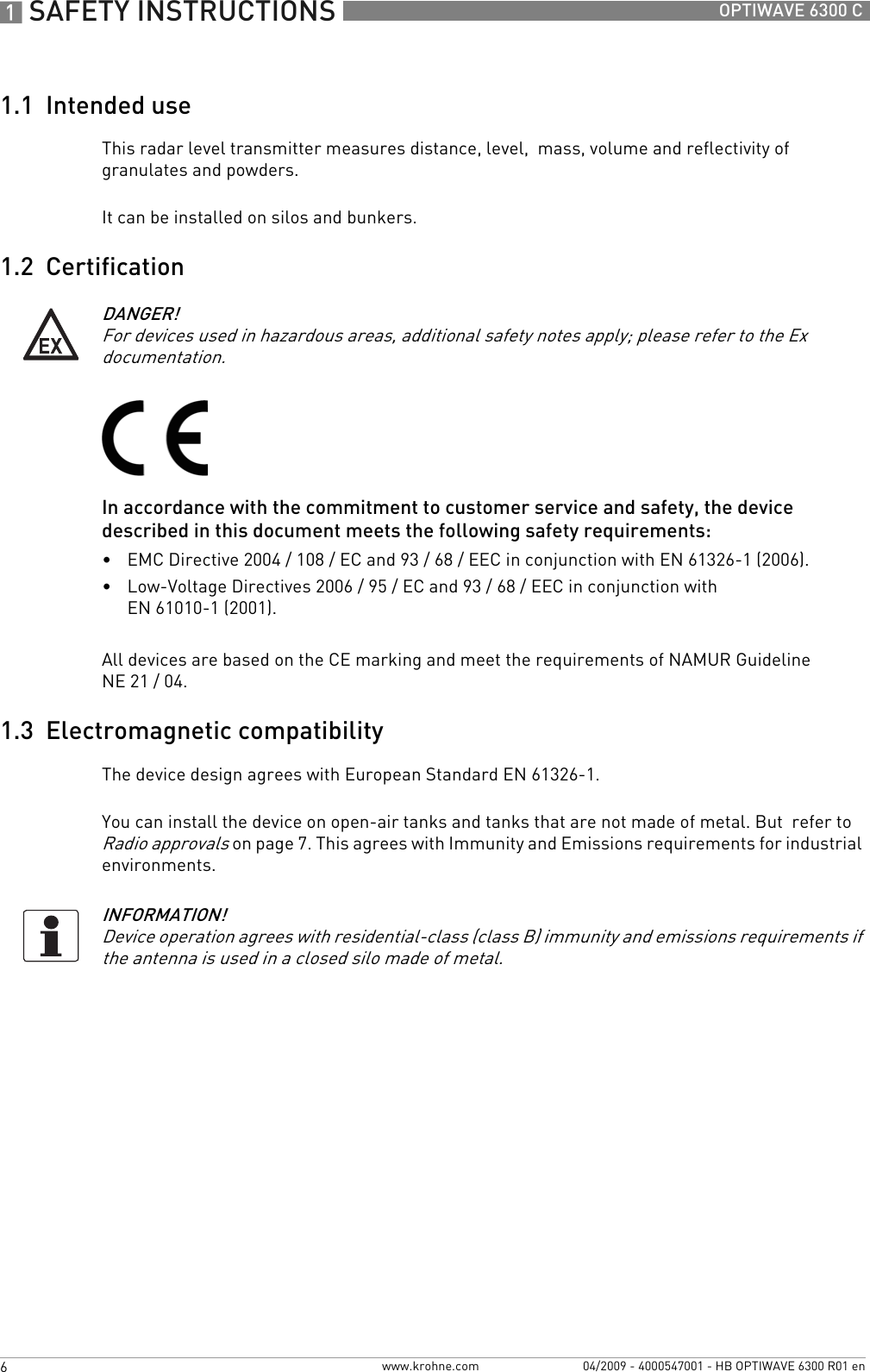
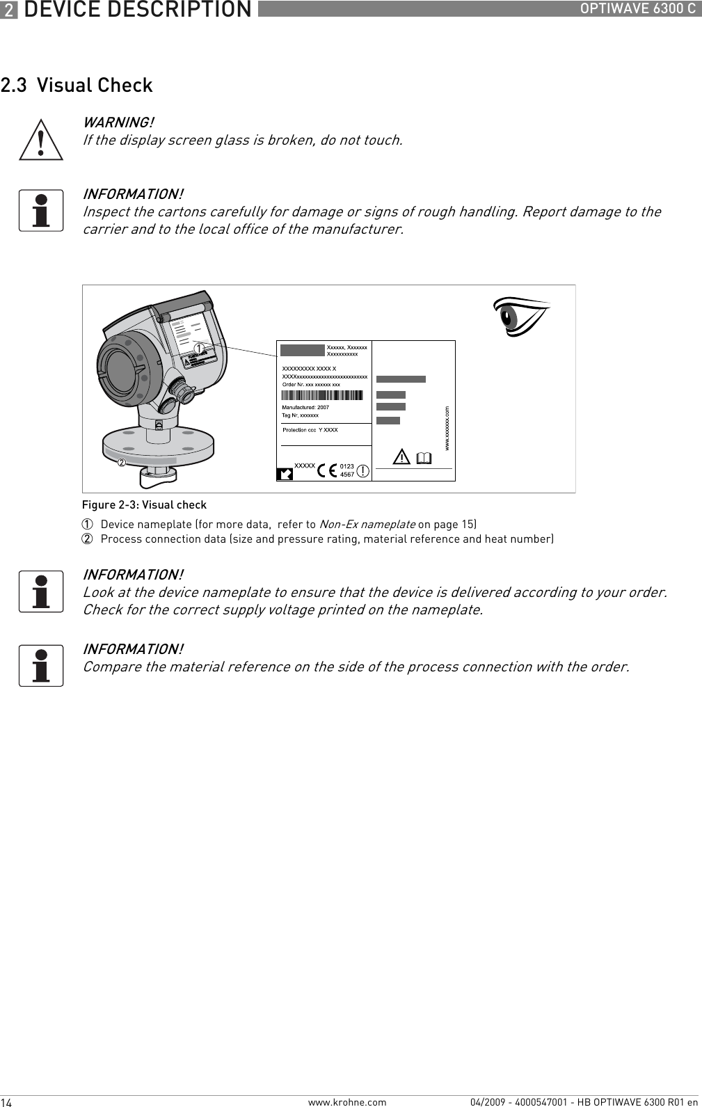
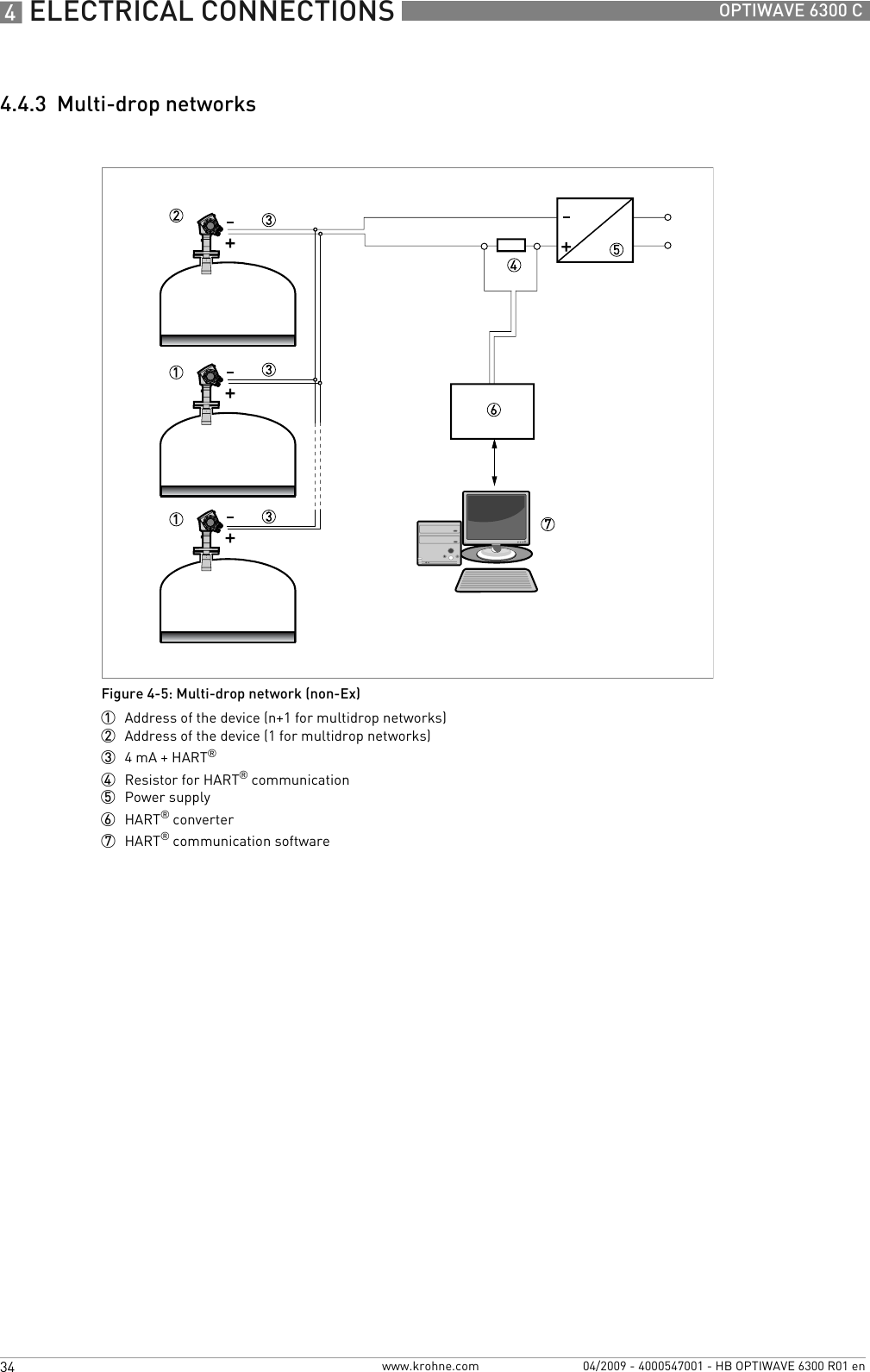
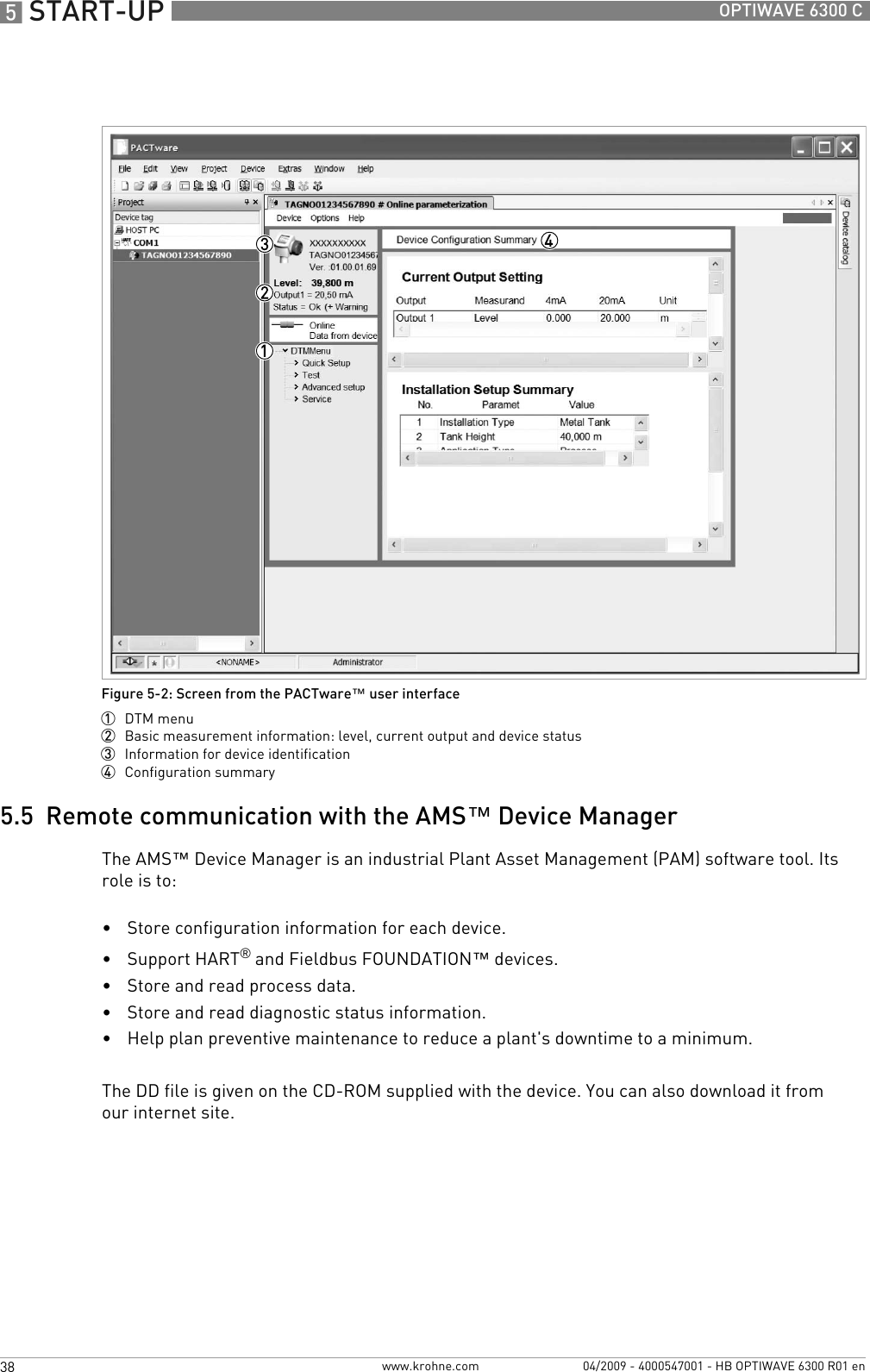
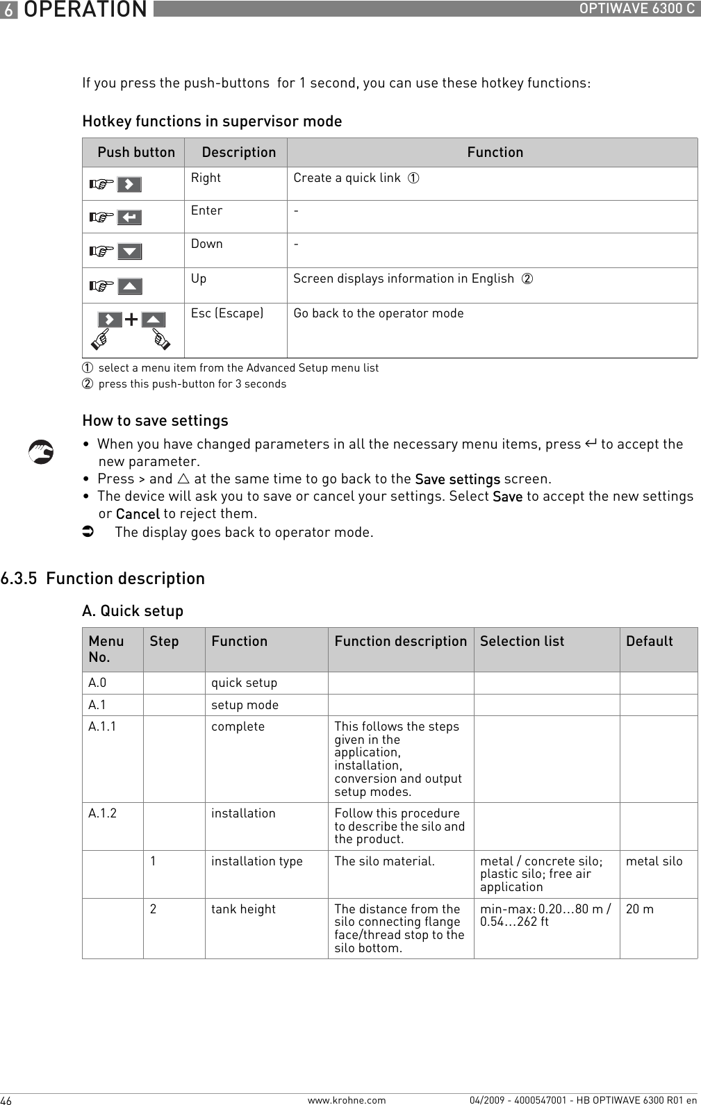
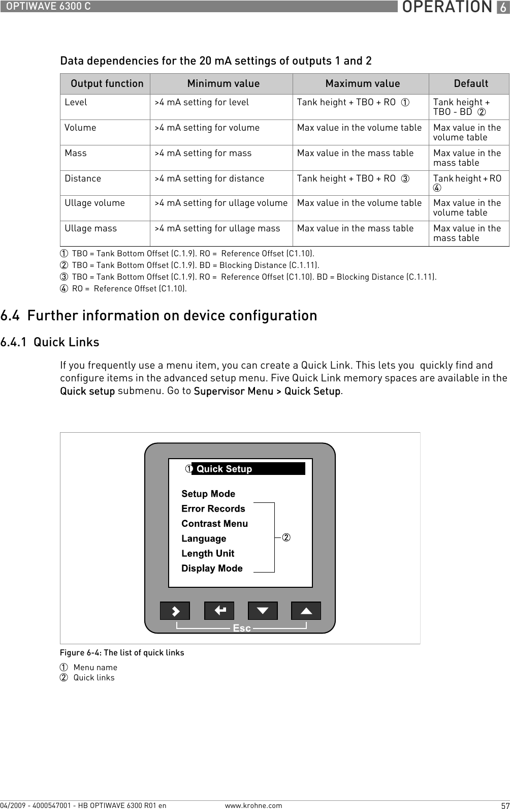
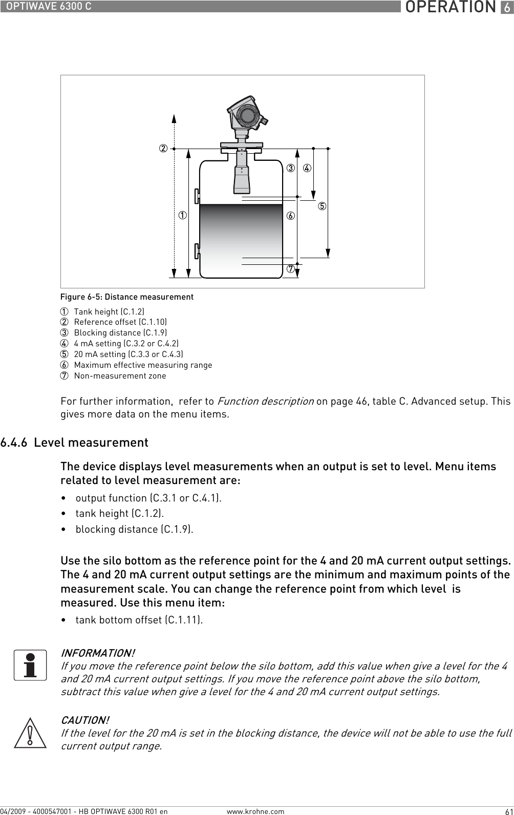
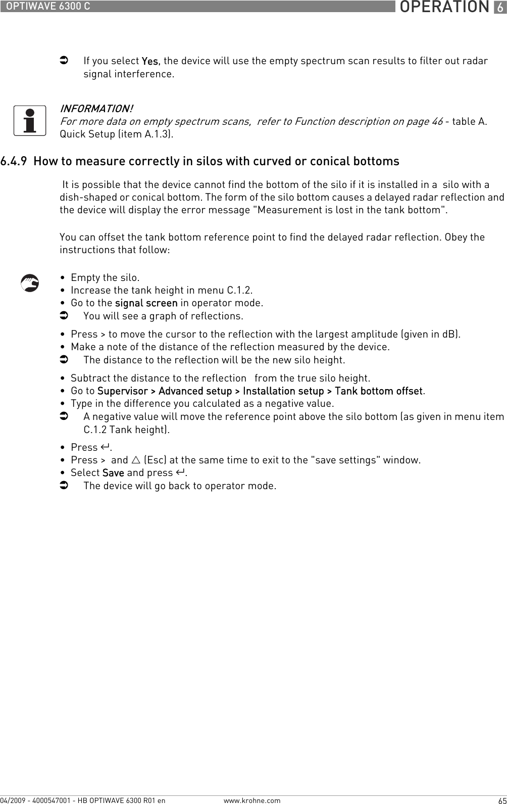
![6 OPERATION 48 OPTIWAVE 6300 Cwww.krohne.com 04/2009 - 4000547001 - HB OPTIWAVE 6300 R01 en8do you want to save the spectrum? If you save this data, the device will use it when it measures the silo contents.save, cancel 2 saveA.1.4 conversion Follow this procedure to set the device up to display readings in volume, mass or user-defined units.sub-menu conversion submenu [volume]1free unit yes, no no2table length unit m, cm, mm, inch, ft, free unit m3conversion wizard volume4tank shape This sub-procedure uses the information given here to find the volume. You have to type in the silo shape, height, width and length.... ...5conversion unit The displayed unit in operator mode. m³, L, US gal, GB gal, ft³, bbl m³6conversion table A table that converts product level to product volume.sub-menu conversion submenu [mass] -1free unit yes, no no2table length unit m, cm, mm, inch, ft, free unit m3conversion wizard mass4type in product density? yes, no yes5product density min-max: 0…20000 kg/m3 06tank shape This sub-procedure uses the information given here to find the volume. You have to type in the silo shape, height, width and length.... ...7conversion unit The conversion unit is given as a volume if the product density is given. If not, choose a mass unit.m³, L, US gal, GB gal, ft³, bbl or Tons, kg, US Tons, GB Tonsm³ or Tons8conversion table A table that converts product level to product mass.sub-menu conversion submenu [free unit]If you cannot find the units or silo shape in the menu, you can customize the conversion table.-Menu No.Step Function Function description Selection list Default](https://usermanual.wiki/KROHNE/FMCW2463/User-Guide-1249910-Page-48.png)
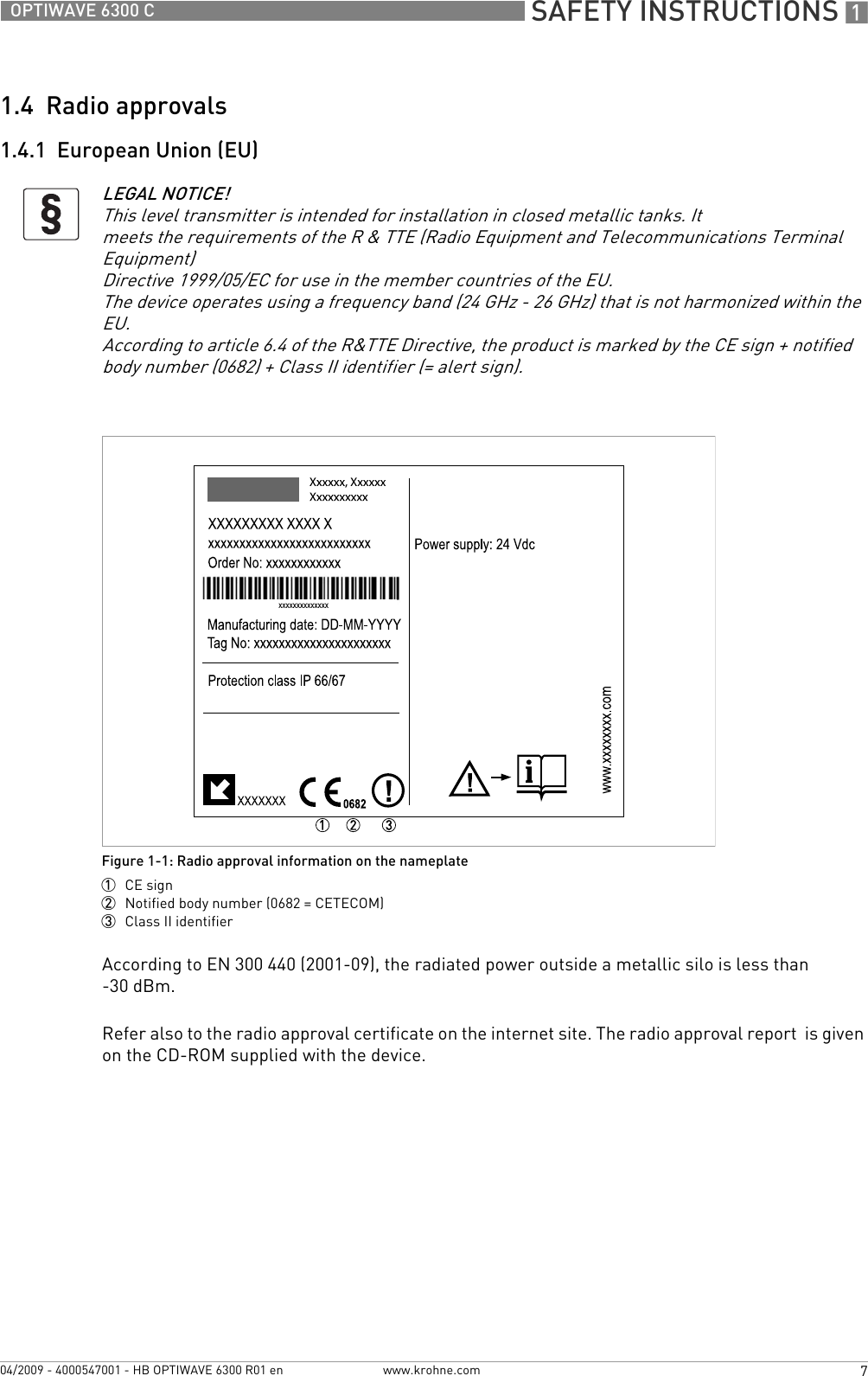
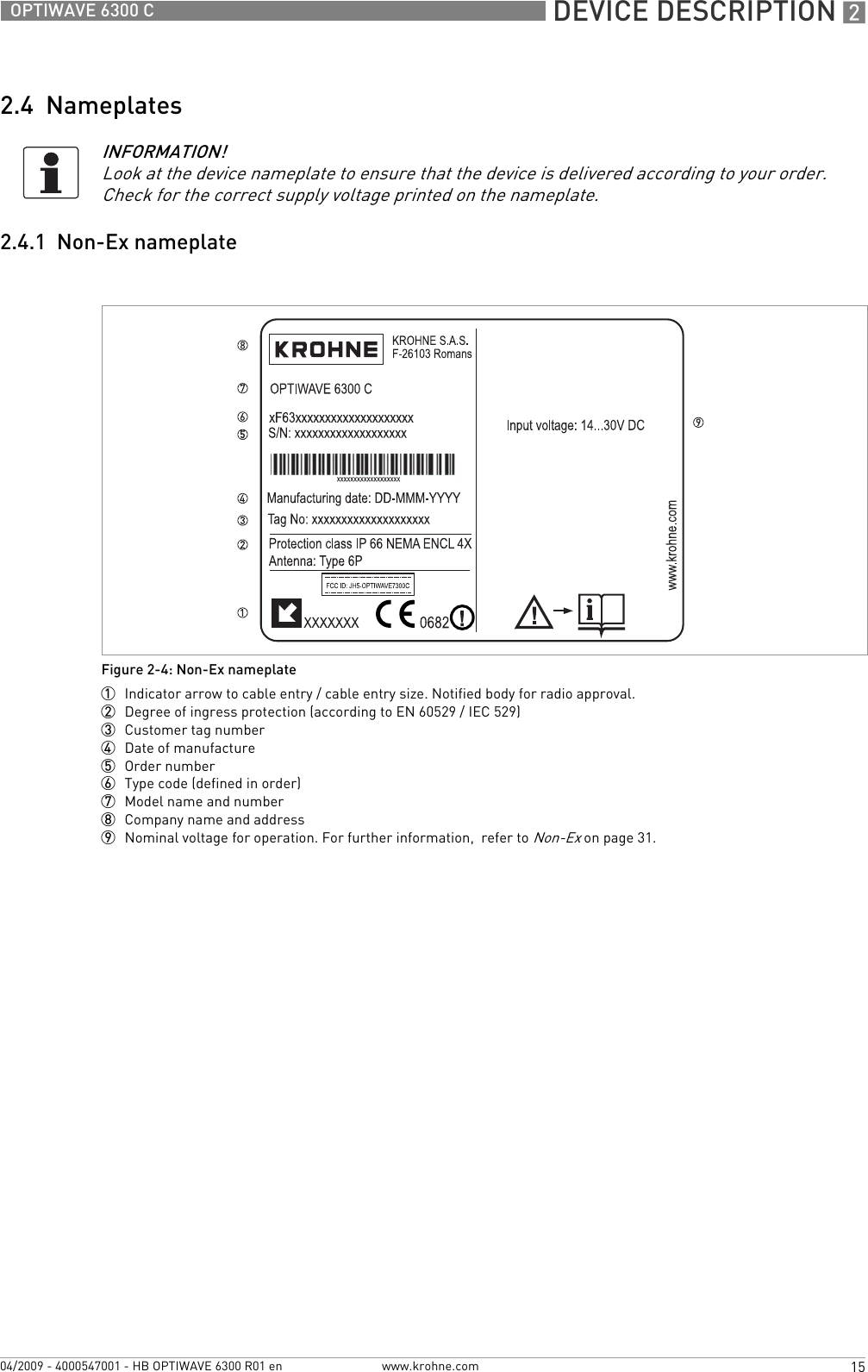
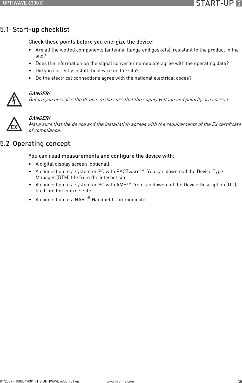
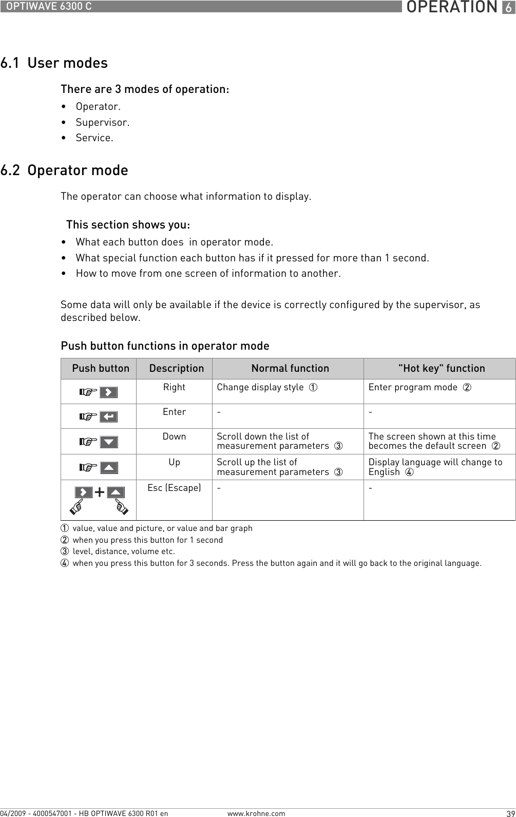
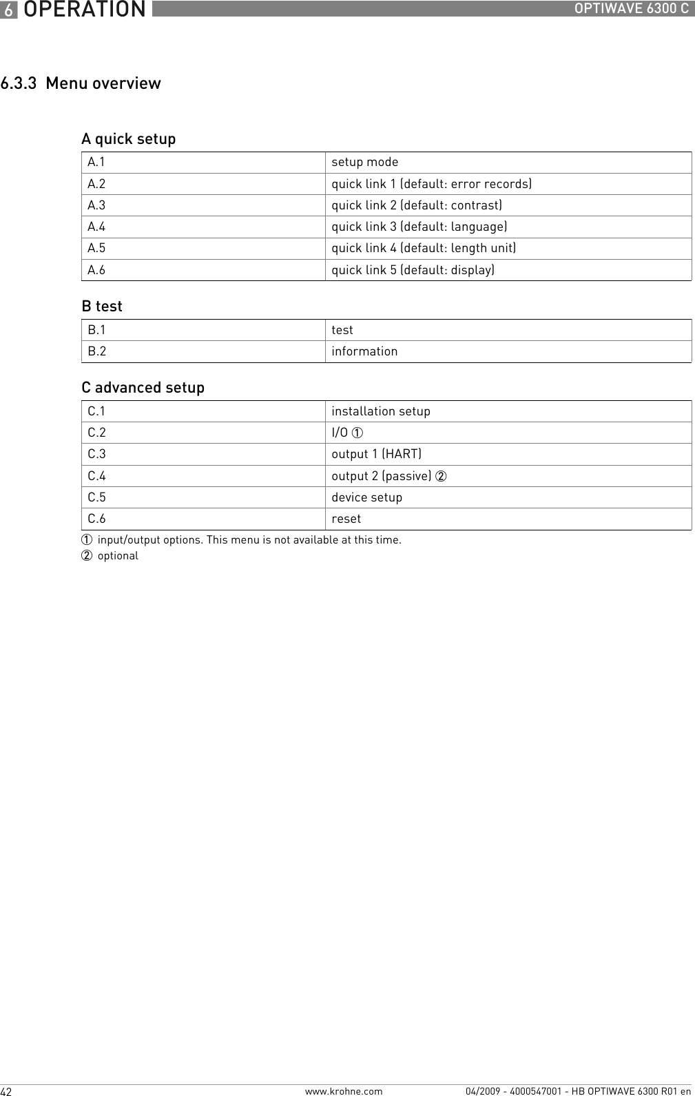
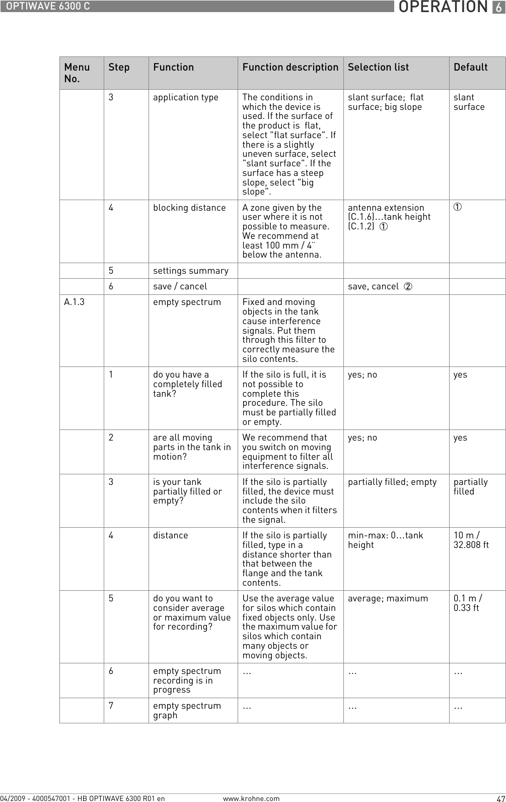
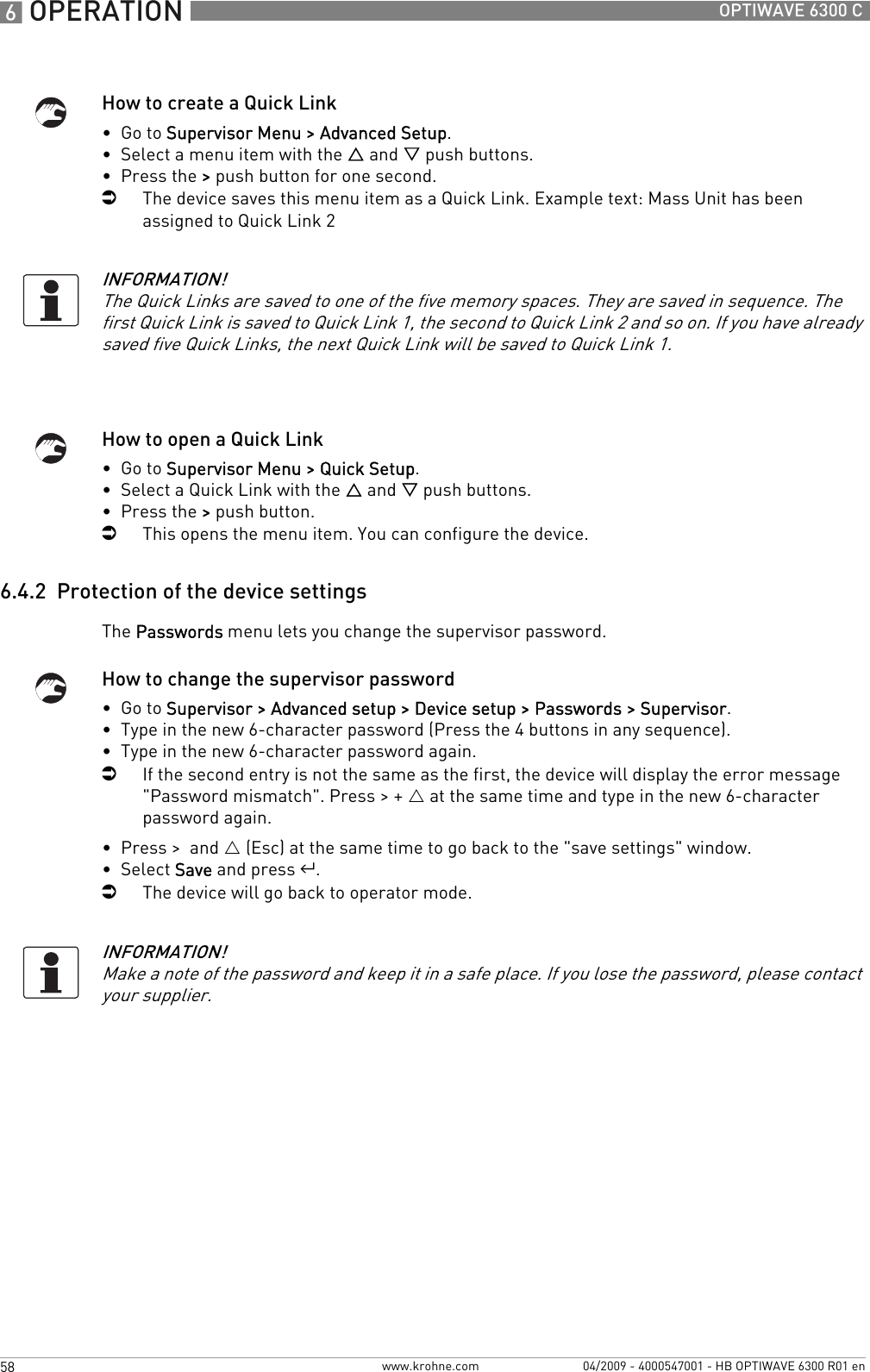
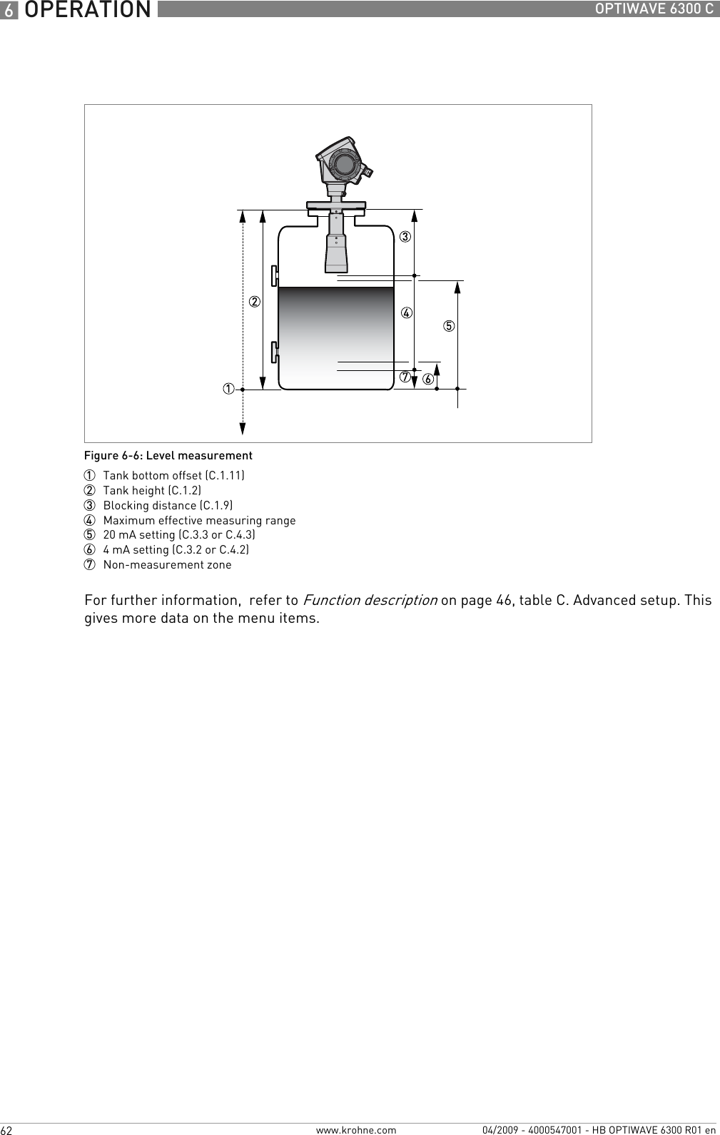
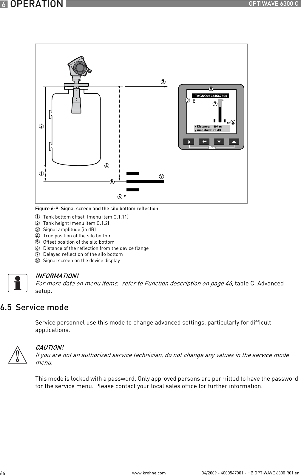
![6 OPERATION 50 OPTIWAVE 6300 Cwww.krohne.com 04/2009 - 4000547001 - HB OPTIWAVE 6300 R01 enB. Test10 output 2: 20 mA setting 3This assigns a measurement value to 20 mA.min.-max: 0…90 m / 0…295.29 ft depends on the output function11 output 2: output range 3This sets the effective range of output 2 with or without over-run.3.8…20.5 mA (NAMUR), 4…20 mA 4…20 mA12 output 2: error handling 3This sets the behaviour of current output 2 if an error occurs.3.6 mA, 22 mA, Hold (4...20 mA range only) 22 mA13 settings summary read onlysave / cancel save, cancel 2 saveA.2 quick link 1 Direct link to an item in the advanced setup menugo to a function in the advanced setup menu and press > for 1 second. You can store up to 5 functions in this way. error recordsA.3 quick link 2 Direct link to an item in the advanced setup menugo to a function in the advanced setup menu and press > for 1 second. You can store up to 5 functions in this way. measurement qualityA.4 quick link 3 Direct link to an item in the advanced setup menugo to a function in the advanced setup menu and press > for 1 second. You can store up to 5 functions in this way. languageA.5 quick link 4 Direct link to an item in the advanced setup menugo to a function in the advanced setup menu and press > for 1 second. You can store up to 5 functions in this way. length unitA.6 quick link 5 Direct link to an item in the advanced setup menugo to a function in the advanced setup menu and press > for 1 second. You can store up to 5 functions in this way. display mode1depends on other user functions2step ignored if complete setup selected3optionalMenu No.Function Function description Selection list DefaultB.0 testB.1 test This checks the device outputs and performs common device tests.B.1.1 show output 1 This displays analogue output 1 value [mA]. read onlyMenu No.Step Function Function description Selection list Default](https://usermanual.wiki/KROHNE/FMCW2463/User-Guide-1249910-Page-50.png)
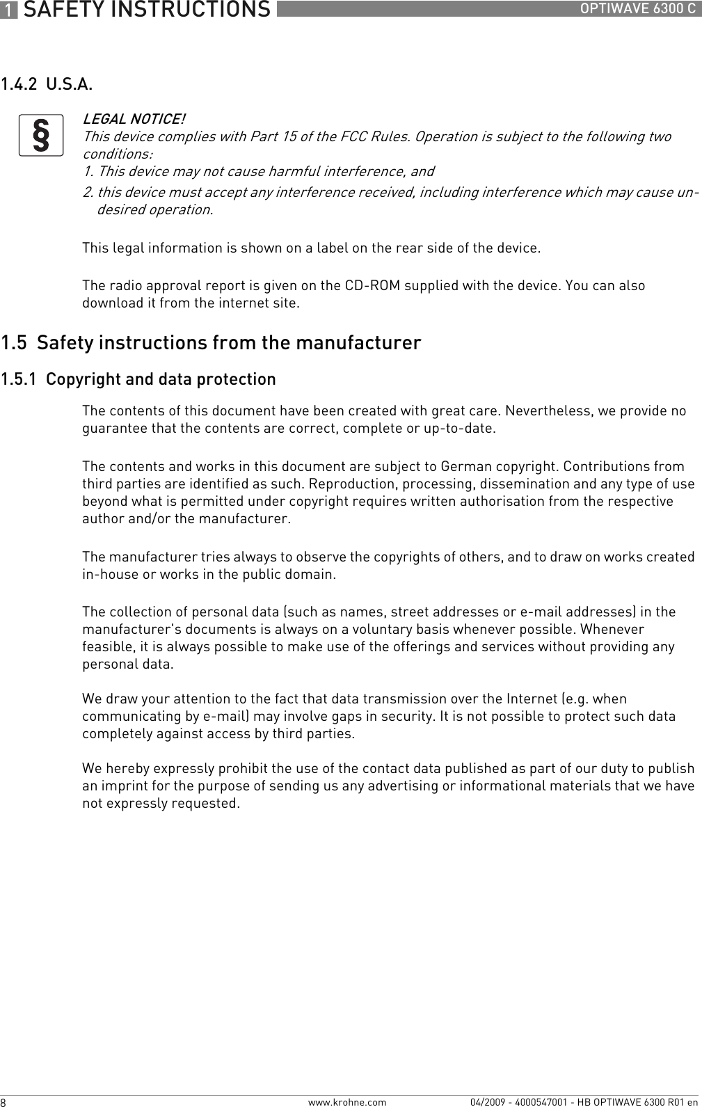
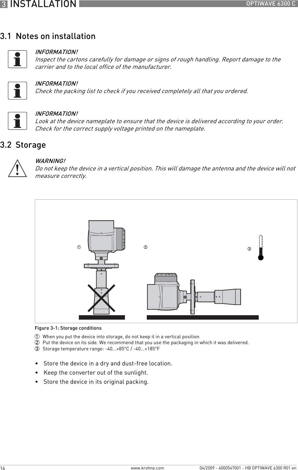
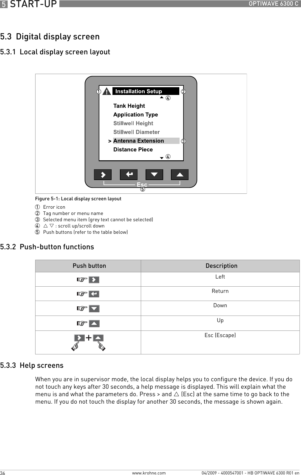
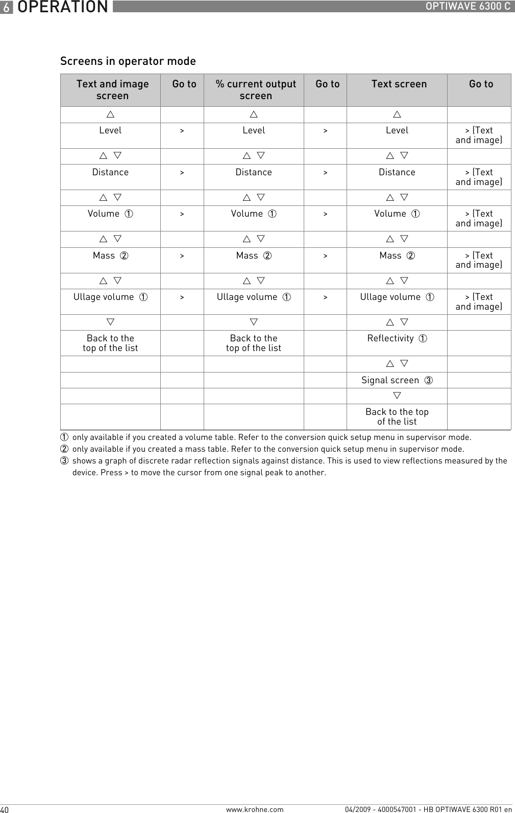
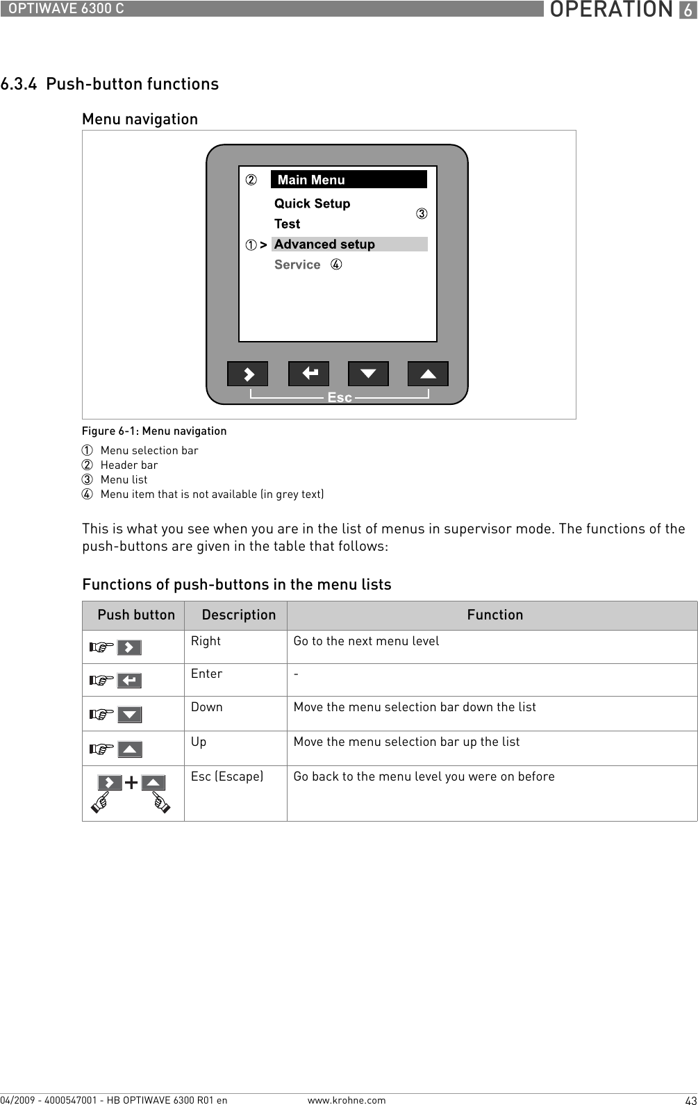
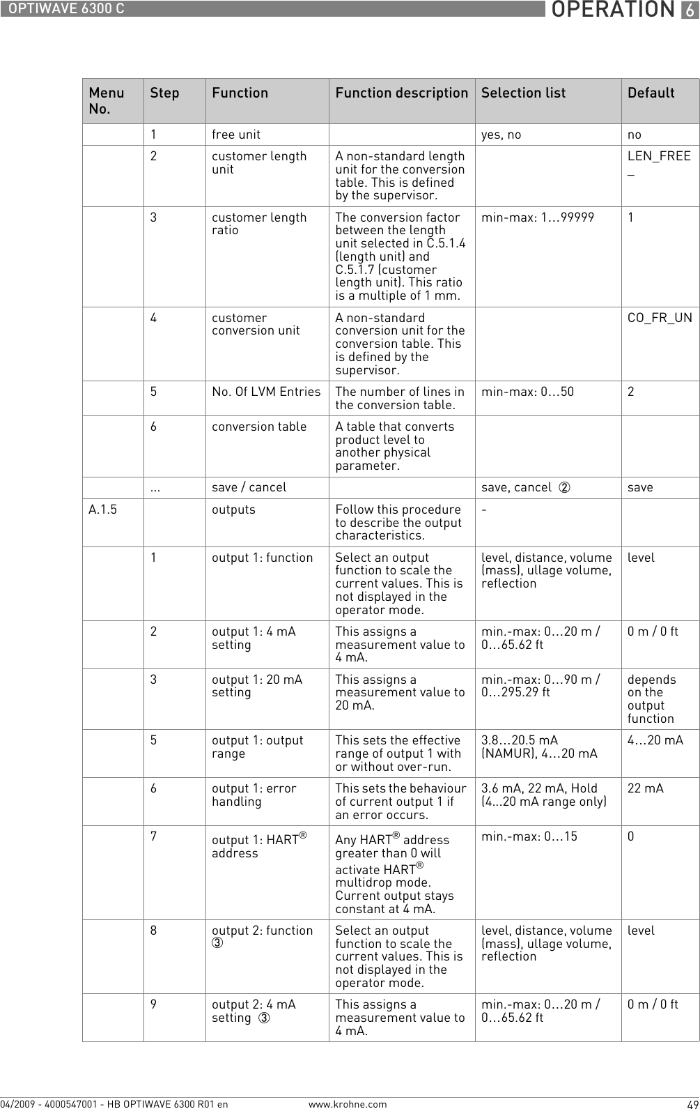
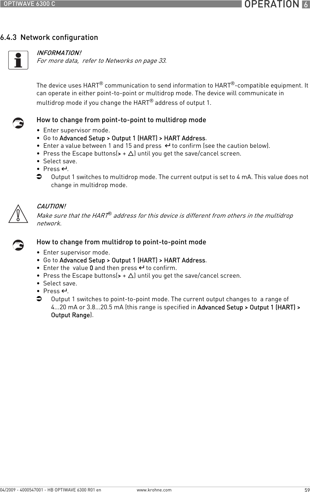
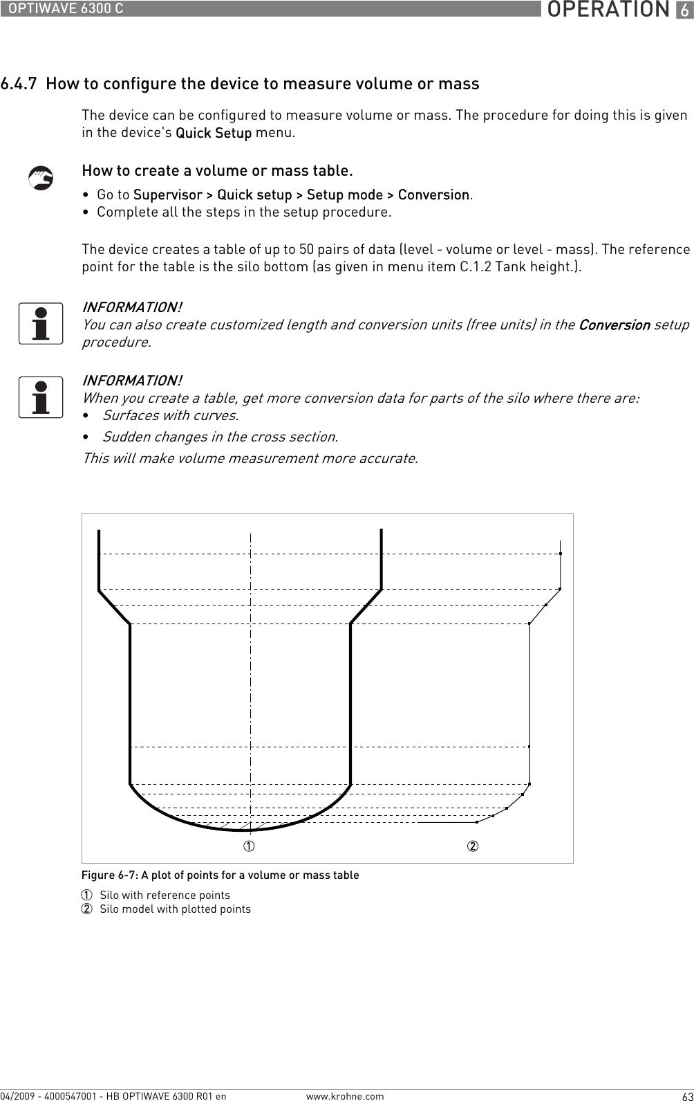
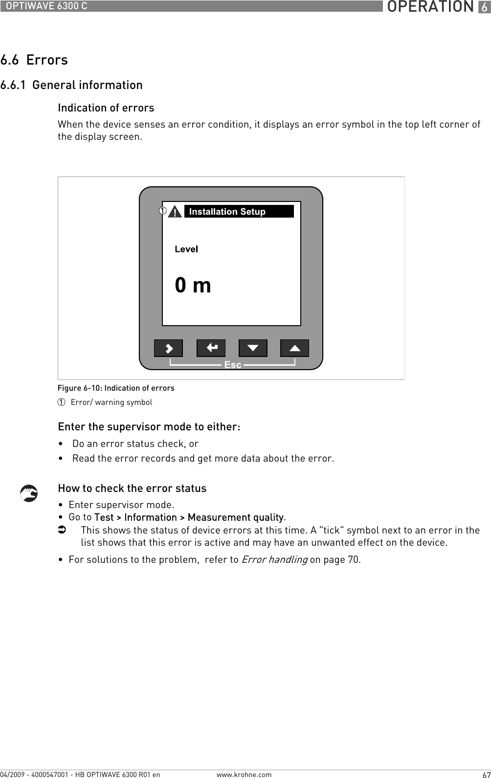
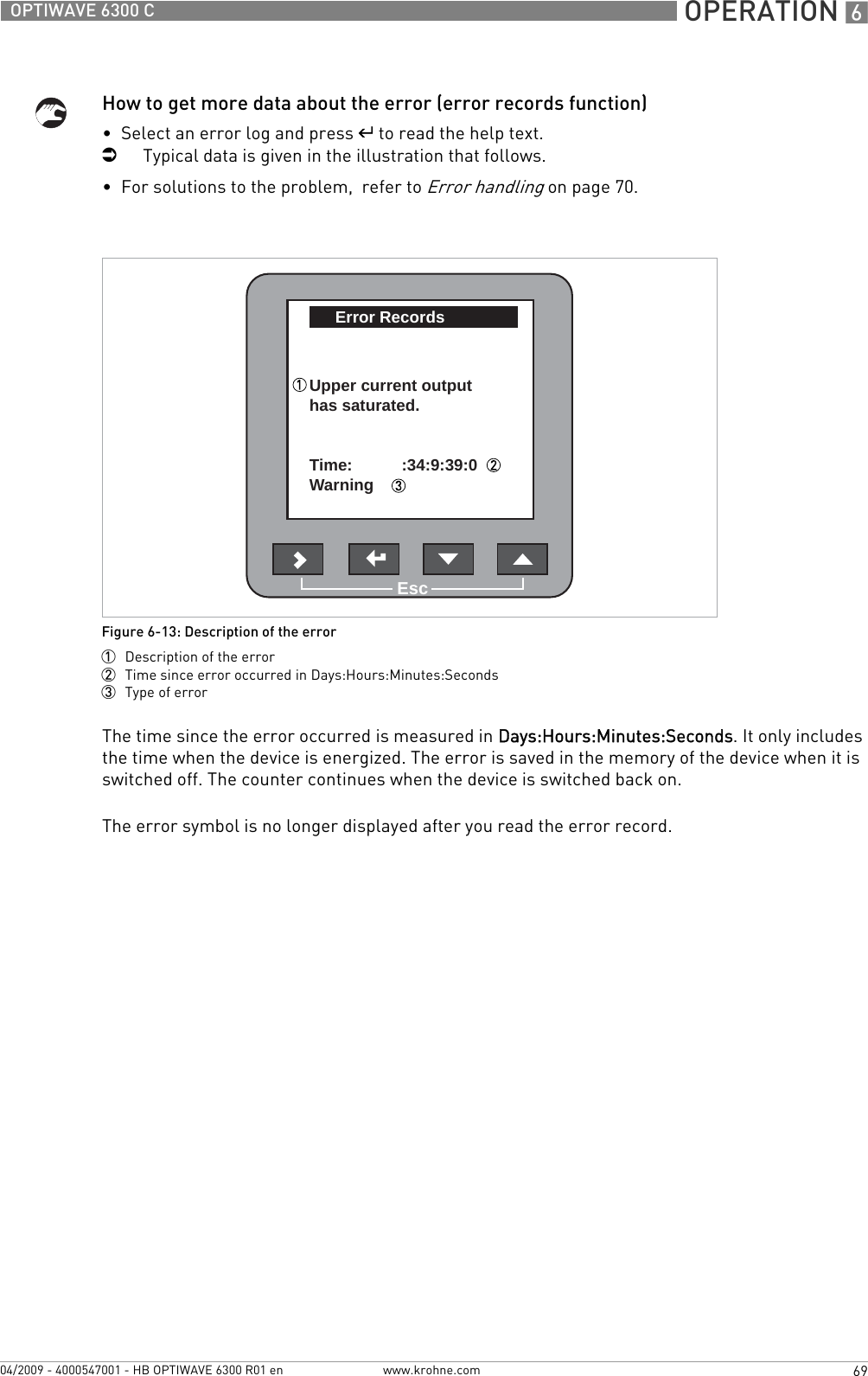
![OPERATION 651OPTIWAVE 6300 Cwww.krohne.com04/2009 - 4000547001 - HB OPTIWAVE 6300 R01 enB.1.2 set output 1 This sets analogue output 1 to a test value [mA] selected from a list. Output will change to the selected value, independent of the measured value.3.6, 4, 6, 8, 10, 12, 14, 16, 18, 20 or 22 mA 4mAB.1.3 show output 2 This displays analogue output 2 value [mA]. read onlyB.1.4 set output 2 This sets analogue output 2 to a test value [mA] selected from a list. Output will change to the selected value, independent of the measured value.3.6, 4, 6, 8, 10, 12, 14, 16, 18, 20 or 22 mA 4mAB.1.5 internal test This initiates the hardware test. The device displays the results. read onlyB.2 information A summary of information relating to the deviceB.2.1 outputs Analogue output settings. This includes assigned functions, 4 … 20 mA scale settings, error handling and HART® parameters.read onlyB.2.2 15 minute log A log of output values for the last 15 minutes. A log is taken every 10 seconds and displayed on a graph.read onlyB.2.3 device identification This displays device order no, V-no, service no, firmware 1 version, firmware 2 version, firmware 3 version and Ex approval details.read onlyB.2.4 quick setup summary A summary of the parameters entered in the quick setup menu read onlyB.2.5 TAG number The TAG number can be seen and updated here ?TAGNO01234567890temperature Temperature of the electronics block. The display will automatically switch off if the temperature is below -20°C / -4°F or above +60°C / +140°Fread onlyB.2.6 error records A log of device errors. Scroll down the list and press ^ to display the error details. Opening a log will remove the error icon if it appeared in operator mode.read onlymeasurement quality Status of device errors at this time. A "tick" symbol next to an error in the list shows that this error is active and may have an unwanted effect on the device.read onlyB.2.7 customer length unit Non-standard length unit for the conversion table. This is defined by the supervisor. Go to supervisor > advanced setup > device setup > display settings > customer length unit or follow the conversion quick setup procedure.read onlyB.2.9 customer conversion unit Non-standard conversion unit for the conversion table. This is defined by the supervisor. Go to supervisor > advanced setup > device setup > display settings > customer conversion unit or follow the conversion quick setup procedure.read onlyMenu No.Function Function description Selection list Default](https://usermanual.wiki/KROHNE/FMCW2463/User-Guide-1249910-Page-51.png)
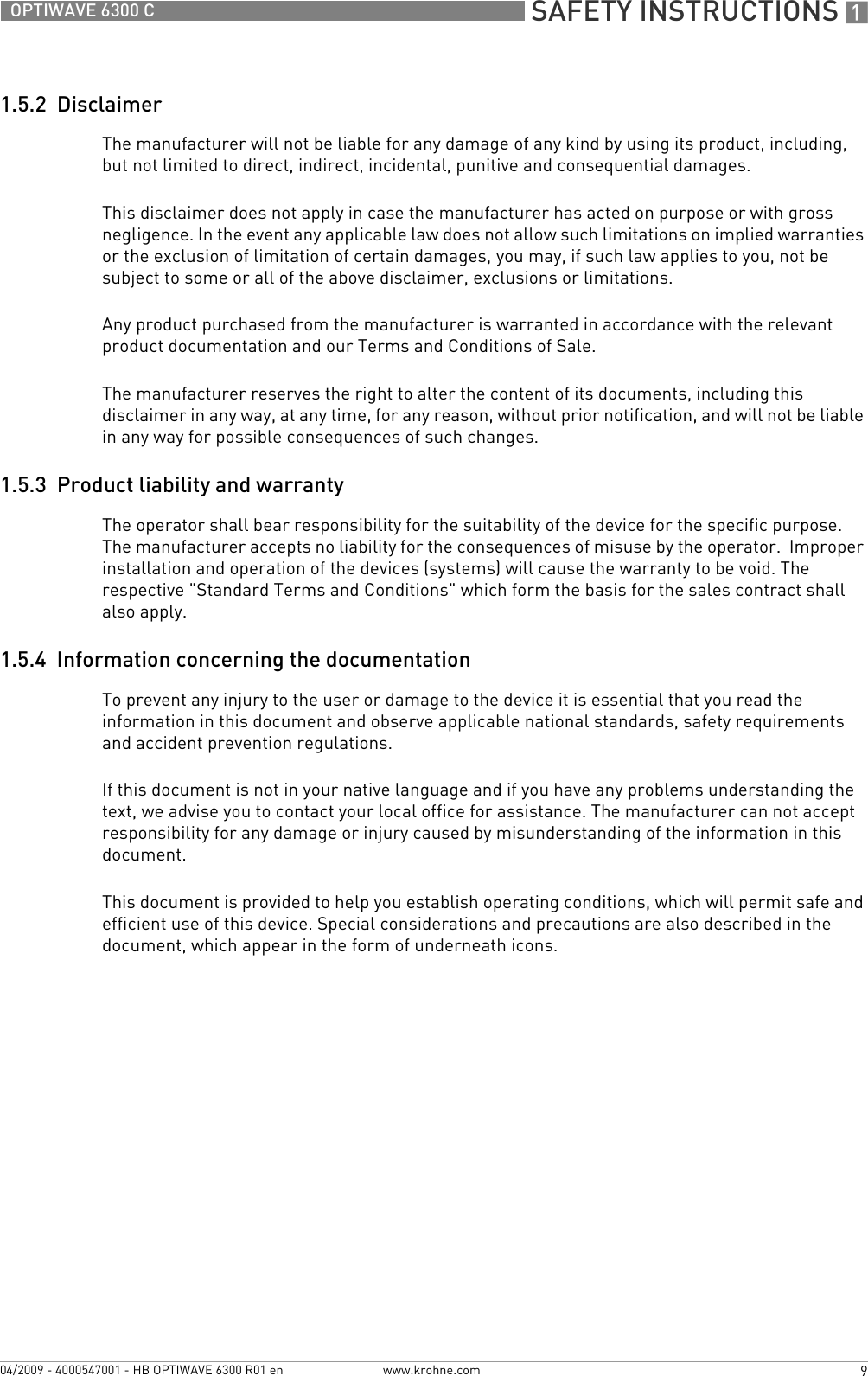
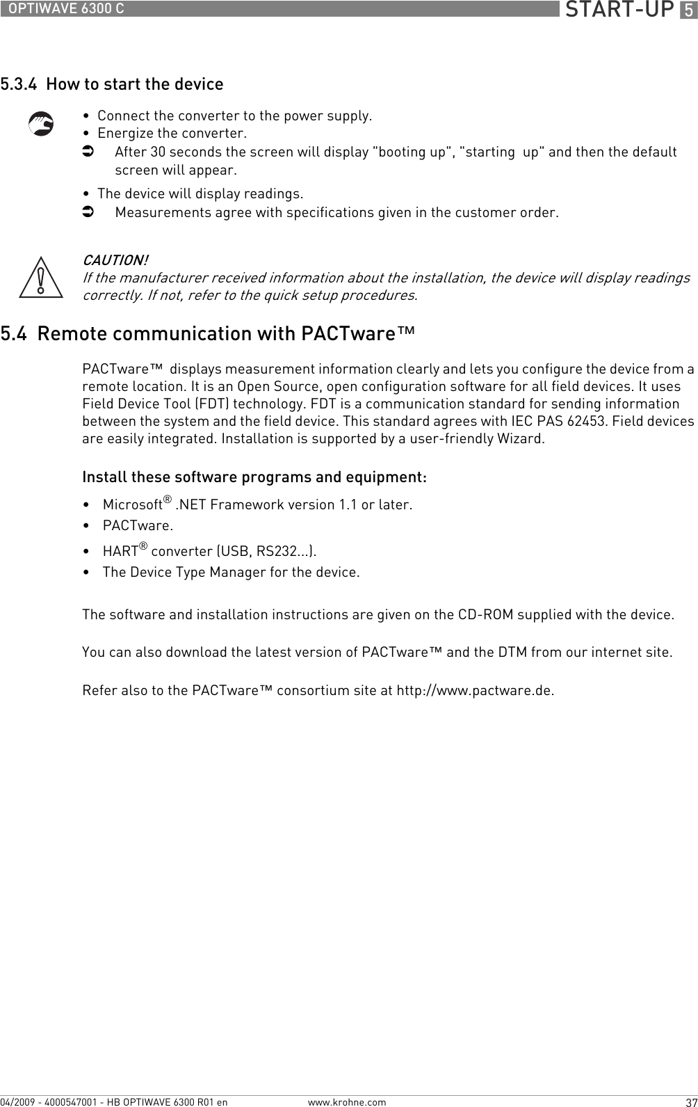
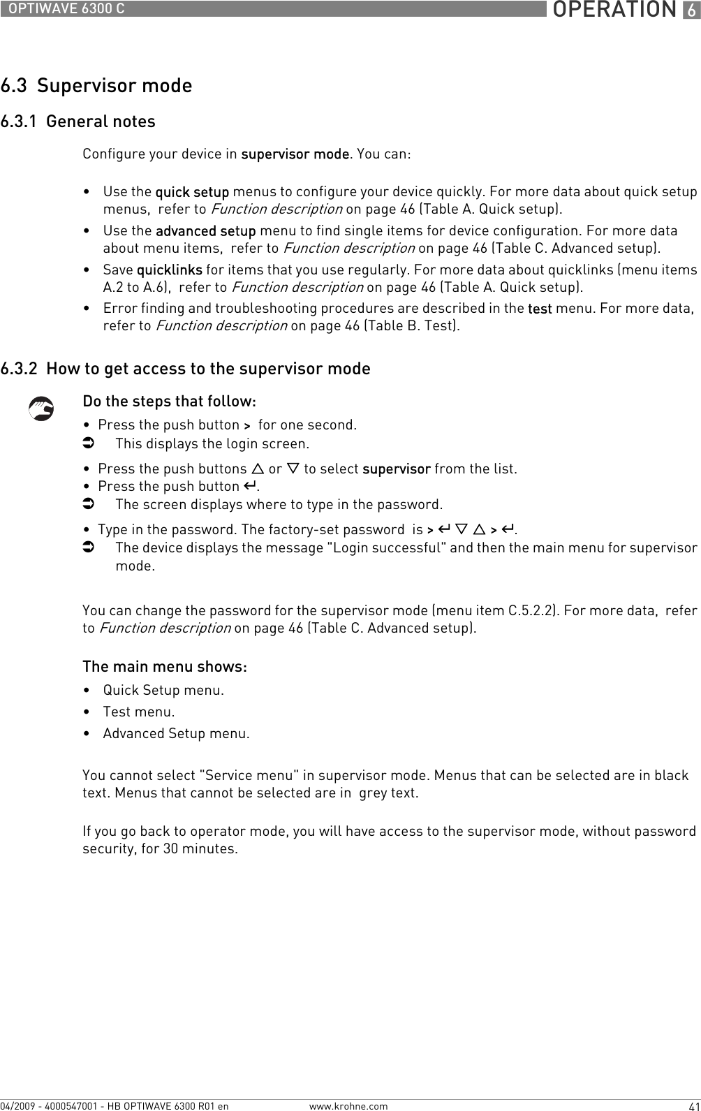
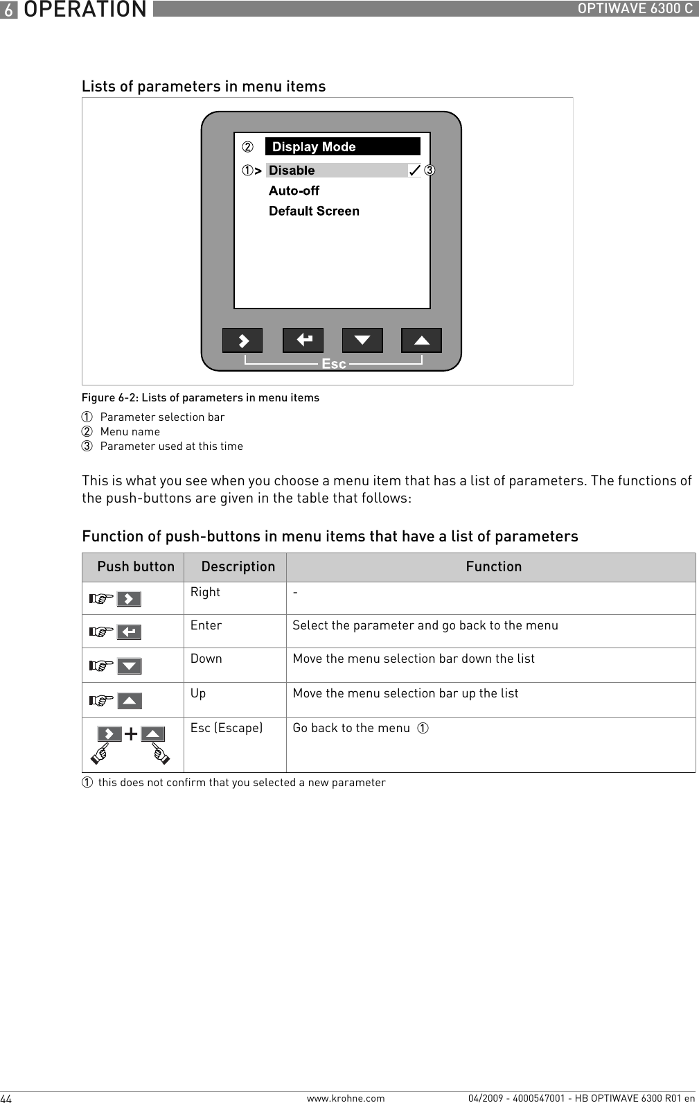
![SERVICE 783OPTIWAVE 6300 Cwww.krohne.com04/2009 - 4000547001 - HB OPTIWAVE 6300 R01 enPart numbers for spare partsItem number Description Quantity Part reference1Combined backend and high-frequency modules 1 1F2139580100Screws for the combined back end and HF modules 2F31773600002HMI cover and cable 2 1XF63400000000503003Terminal module with 1 output (non-Ex) 1F2139620200Terminal module with 1 output (Ex ia) 1F2139620100Terminal module with 1 output (Ex d [ia]) 1F2139950100Terminal module with 2 outputs (non-Ex) 1F2139630200Terminal module with 2 outputs (Ex ia) 1F2139630100Terminal module with 2 outputs (Ex d [ia]) 1F2139640100Screws for the terminal module 2F31773500001the customer must send the original back end and HF module to the repair centre. Refer to the replacement procedure in this section.2this reference includes the gasket and screws](https://usermanual.wiki/KROHNE/FMCW2463/User-Guide-1249910-Page-83.png)
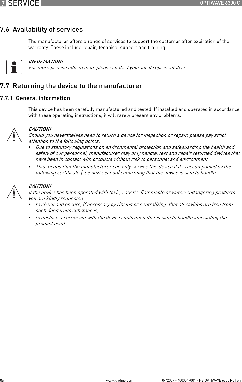
![8 TECHNICAL DATA 92 OPTIWAVE 6300 Cwww.krohne.com 04/2009 - 4000547001 - HB OPTIWAVE 6300 R01 enApprovals and certificationCE This device fufills the statutory requirements of the EC directives. The manufacturer certifies successful testing of the product by applying the CE mark.Explosion protectionATEX ATEX II G 1, 1/2, 2 Ex ia IIC T6...T3;ATEX II D 1, 1/2, 2 Ex iaD 20 or Ex iaD 20/21 or Ex iaD 21 IP6X T65°C...T90°C;ATEX II G 1/2, 2 Ex d [ia] IIC T6...T3;ATEX II D 1/2, 2 Ex tD[iaD] A21/20 or Ex tD[iaD] A21 IP6X T65°C...T90°CIECEx (pending) Zone 0 Ex ia IIC T6…T3; Ex iaD 20 IP6X T65°C…T 90°CFM or CSA - Dual Seal-approved (available in Q4/2009) NEC 500/ CEC:Cl. I, Div. 1, Gr. ABCD (IS);Cl. I, Div. 1, Gr. ABCD (FM only) (XP);Cl. I, Div. 2, Gr. ABCD (XP/NI);Cl. II, Div. 1, Gr. EFG; Cl. III (FM only) (XP);Cl. II, Div. 1, Gr. EFG; Cl. III (IS);Cl. II/III, Div . 2, Gr. FG (XP/NI)NEC 505/ CEC:Cl. I, Zone 0 AEx ia Gr. IIC (CSA: Ex ia) (IS);Cl. I, Zone 1 AEx d [ia] Gr. IIC (XP);Cl. I, Zone 2, AEx nA [ia], Gr. IIC (CSA: Ex nA [ia]) (IS)Other standards and approvalsEMC EMC Directive 2004 / 108 / EC and 93 / 68 / EEC in conjunction with EN 61326-1 (2006).LVD Low-Voltage Directives 2006 / 95 / EC and 93 / 68 / EEC in conjunction with EN 61010-1 (2001).NAMUR NAMUR NE 21 Electromagnetic Compatibility (EMC) of Industrial Process and Laboratory Control EquipmentNAMUR NE 43 Standardization of the Signal Level for the Failure Information of Digital Transmitters1Hastelloy® is a registered trademark of Haynes International, Inc.2Kalrez® is a registered trademark of DuPont Performance Elastomers L.L.C.3Metaglas® is a registered trademark of Herberts Industrieglas, GMBH & Co., KG4HART® is a registered trademark of the HART Communication Foundation](https://usermanual.wiki/KROHNE/FMCW2463/User-Guide-1249910-Page-92.png)
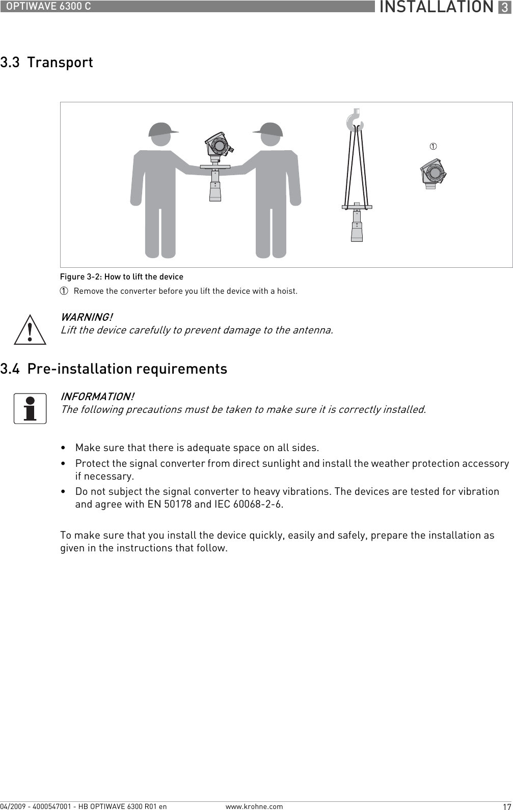
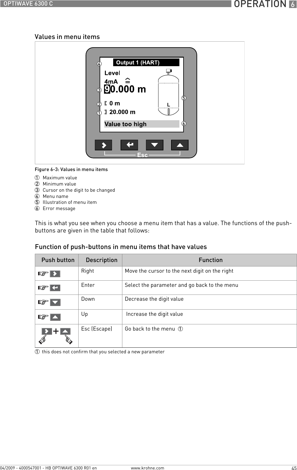
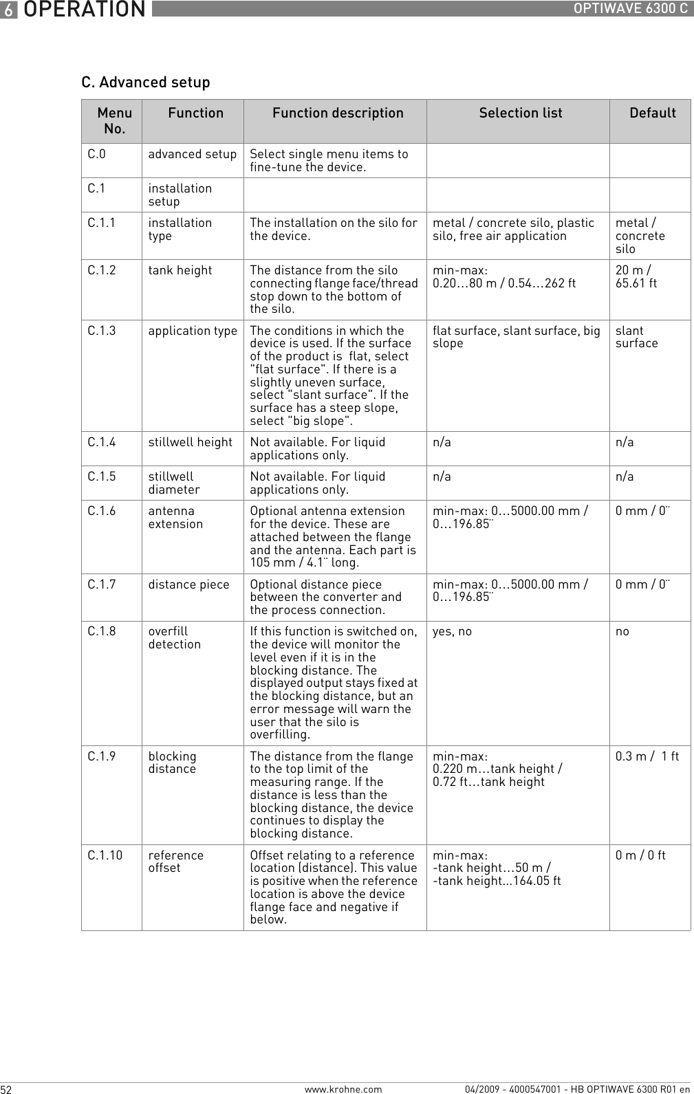
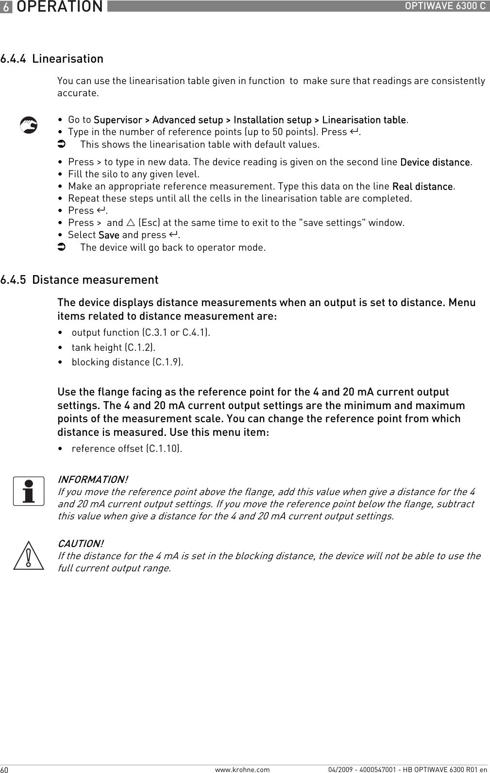
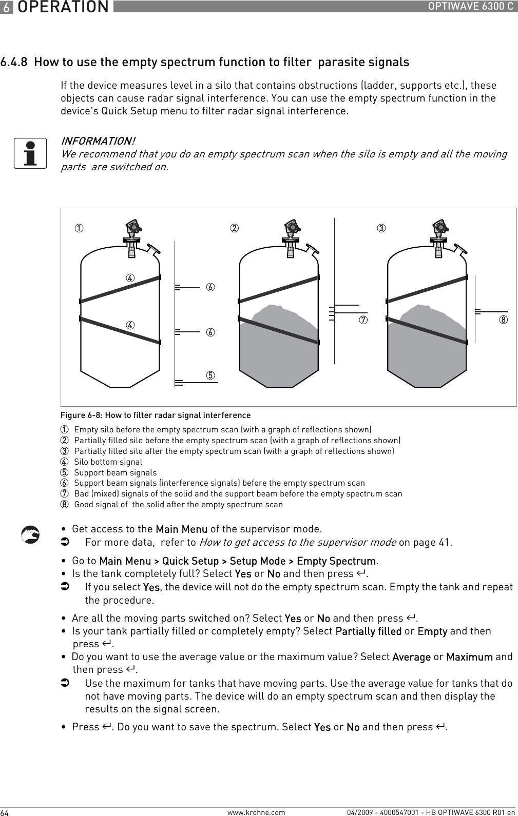
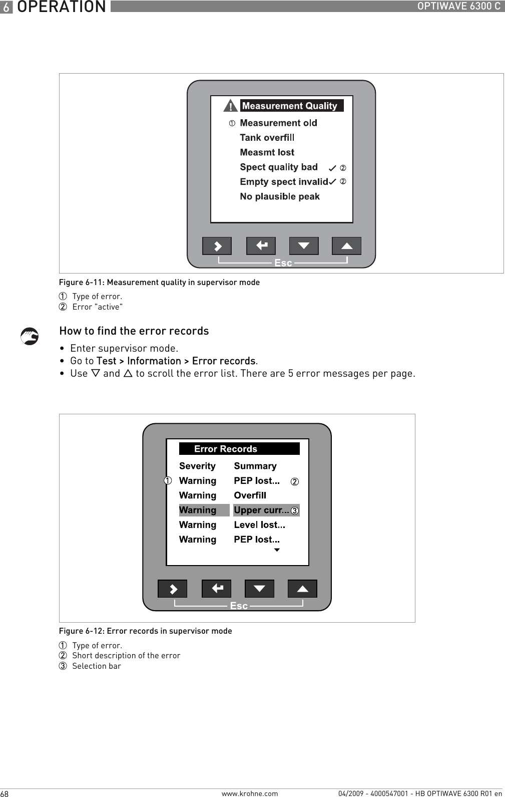
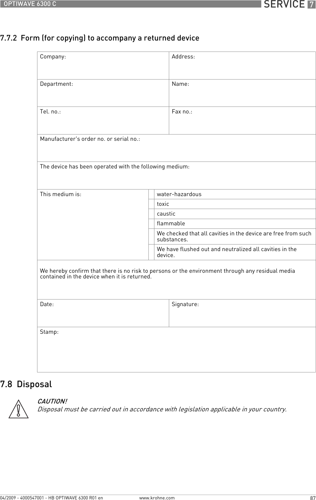
![TECHNICAL DATA 893OPTIWAVE 6300 Cwww.krohne.com04/2009 - 4000547001 - HB OPTIWAVE 6300 R01 en8.3 Antenna selectionThis graph shows which antenna to select for the application based on:•D, the measuring range and•εr, is the dielectric constant of the product being measuredFigure 8-2: Selection of antenna for solid applications (graph of distance in m against εr)Figure 8-3: Selection of antenna for solid applications (graph of distance in ft. against εr)1 Distance, D [m]2 Distance, D [ft]3 Dielectric constant (εr) 4 On request5 DN 150 Drop antenna6 DN 100 horn and DN 150 Drop antenna7 DN 80 horn, DN 80 Drop, DN 100 horn and DN 150 Drop antenna153746123456789100102030405060708024357612345678910+0203040607080100120130140160180190200220240260](https://usermanual.wiki/KROHNE/FMCW2463/User-Guide-1249910-Page-93.png)
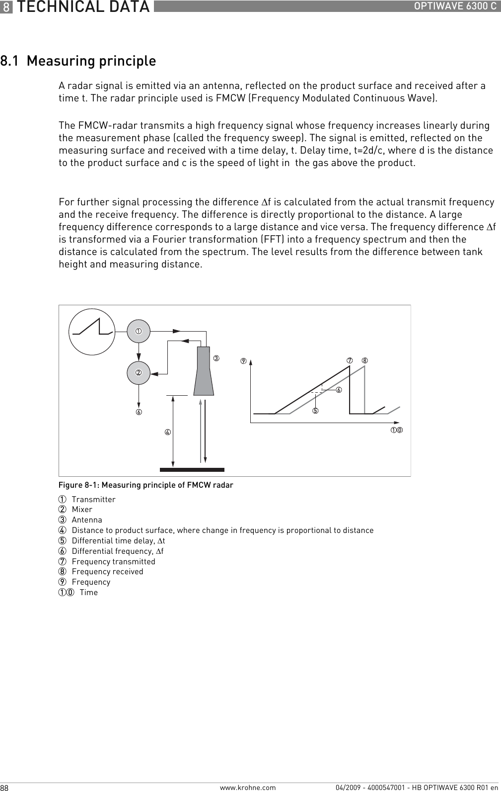
![8 TECHNICAL DATA 94 OPTIWAVE 6300 Cwww.krohne.com 04/2009 - 4000547001 - HB OPTIWAVE 6300 R01 en8.4 Dimensions and weightsDimensions and weights in mm and kgDimensions and weights in inches and lbsHousingFigure 8-4: Housing dimensions1 Housing front view2 Housing side viewDimensions [mm] Weights [kg]a b c d e f gHousing 180 122 158.5 182 1 167 277 155 3.31if fitted with standard cable glandsDimensions [inches] Weights [lbs]a b c d e f gHousing 7.1 4.8 6.2 7.2 1 6.5 10.9 6.1 7.31if fitted with standard cable glandsCAUTION!•Cable glands are delivered on demand with non-Ex, Ex i- and Ex d-approved devices.•The diameter of the outer sheath of the cable must be 6…12 mm or 0.2…0.5¨.•Cable glands for FM- or CSA-approved devices must be supplied by the customer.•A weather protection cover is available on request with all devices.](https://usermanual.wiki/KROHNE/FMCW2463/User-Guide-1249910-Page-94.png)
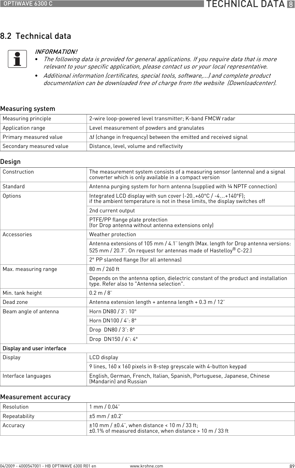
![TECHNICAL DATA 895OPTIWAVE 6300 Cwww.krohne.com04/2009 - 4000547001 - HB OPTIWAVE 6300 R01 enDimensions and weights in mm and kgDimensions and weights in inches and lbsWeather protectionFigure 8-5: Dimensions of the weather protection option1 Weather protection, back view2 Weather protection, left side viewDimensions [mm] Weights [kg]a b c dWeather protection208 231.5 268 1 66 2.91radiusDimensions [inches] Weights [lbs]a b c dWeather protection8.2 9.1 10.6 1 2.6 6.41radius](https://usermanual.wiki/KROHNE/FMCW2463/User-Guide-1249910-Page-95.png)
![8 TECHNICAL DATA 96 OPTIWAVE 6300 Cwww.krohne.com 04/2009 - 4000547001 - HB OPTIWAVE 6300 R01 enDimensions and weights in mm and kgDimensions and weights in inches and lbsDN80/3¨ horn antenna versionsFigure 8-6: DN80/3¨ horn antenna versions1 DN80/3¨ horn antenna with G1½ or 1½NPT thread connection2 DN80/3¨ horn antenna with flange connectionDimensions [mm] Weights [kg]a b c d e f h ØiThread connection182 1 167 201 233 479 32 246 2 75 5.5Flange connection182 1 167 201 246 463 45 217 2 75 6.9…26.21if fitted with standard cable glands2additional antenna extensions of Ø39 x length 105 mm are availableDimensions [inches] Weights [lbs]a b c d e f h ØiThread connection7.2 1 6.5 7.9 9.2 18.9 1.3 9.7 2 312.1Flange connection7.2 1 6.5 7.9 9.7 18.2 1.8 8.5 2 315.2…57.81if fitted with standard cable glands2additional antenna extensions of Ø1.5 x length 4.1¨ are available](https://usermanual.wiki/KROHNE/FMCW2463/User-Guide-1249910-Page-96.png)
![TECHNICAL DATA 897OPTIWAVE 6300 Cwww.krohne.com04/2009 - 4000547001 - HB OPTIWAVE 6300 R01 enDimensions and weights in mm and kgDimensions and weights in inches and lbsDN100/4¨ horn antenna versionsFigure 8-7: DN100/4¨ horn antenna versions1 DN100/4¨ horn antenna with G1½ or 1½NPT thread connection2 DN100/4¨ horn antenna with flange connectionDimensions [mm] Weights [kg]a b c d e f h ØiThread connection182 1 167 201 233 548 32 315 2 95 6.5Flange connection182 1 167 201 246 532 45 286 2 95 7.9…27.21if fitted with standard cable glands2additional antenna extensions of Ø39 x length 105 mm are availableDimensions [inches] Weights [lbs]a b c d e f h ØiThread connection7.2 1 6.5 7.9 9.2 21.6 1.3 12.4 2 3.7 14.3Flange connection7.2 1 6.5 7.9 9.7 20.9 1.8 11.3 2 3.7 17.4…601if fitted with standard cable glands2additional antenna extensions of Ø1.5 x length 4.1¨ are available](https://usermanual.wiki/KROHNE/FMCW2463/User-Guide-1249910-Page-97.png)
![8 TECHNICAL DATA 98 OPTIWAVE 6300 Cwww.krohne.com 04/2009 - 4000547001 - HB OPTIWAVE 6300 R01 enDimensions and weights in mm and kgDimensions and weights in inches and lbsDN80/3¨ Drop antenna versionsFigure 8-8: DN80/3¨ Drop antenna versions1 DN80/3¨ Drop antenna with G1½ or 1½NPT thread connection2 DN80/3¨ Drop antenna with flange connection3 DN80/3¨ Drop antenna with slanted flange connection (PP material option only)4 DN80/3¨ Drop antenna, with PP or PTFE flange plate protection optionDimensions [mm] Weights [kg]a b c d e f h Øi j kThread connection 1821167 201 234 399 33 165274 - - 5.7…6.1Flange connection 1821167 201 246 383 45 137274 - - 6.3…26Flange connection with slanted flange option1821167 201 246 383 45 137274 10 2°6.4…26.6Flange connection with flange plate protection option1821167 201 246 383 45 137 74 39 -6.6…26.81if fitted with standard cable glands2additional antenna extensions of Ø39 x length 105 mm are available. Do not attach more than 5 antenna extensions.Dimensions [inches] Weights [lbs]a b c d e f h Øi j kThread connection 7.216.5 7.9 9.2 15.7 1.3 6.522.9 - - 12.6…13.4Flange connection 7.216.5 7.9 9.7 15.1 1.8 5.422.9 - - 13.9…57.3Flange connection with slanted flange option7.216.5 7.9 9.7 15.1 1.8 5.422.9 0.4 2°14.1…58.6Flange connection with flange plate protection option7.216.5 7.9 9.7 15.1 1.8 5.4 2.9 1.5 -13.9…59.11if fitted with standard cable glands2additional antenna extensions of Ø1.5 x length 4.1¨ available. Do not attach more than 5 antenna extensions.](https://usermanual.wiki/KROHNE/FMCW2463/User-Guide-1249910-Page-98.png)
![TECHNICAL DATA 899OPTIWAVE 6300 Cwww.krohne.com04/2009 - 4000547001 - HB OPTIWAVE 6300 R01 enDimensions and weights in mm and kgDimensions and weights in inches and lbsDN150/6¨ Drop antenna versions (PP material option only)Figure 8-9: DN150/6¨ Drop antenna versions (PP material option only)1 DN150/6¨ Drop antenna with flange connection2 DN150/6¨ Drop antenna with thread connection3 DN150/6¨ Drop antenna with slanted flange connection4 DN150/6¨ Drop antenna, with flange plate protection optionDimensions [mm] Weights [kg]a b c d e f h Øi j kThread connection 1821167 201 234 476 33 2422144 - - 7.4Flange connection 1821167 201 246 460 45 2142144 - - 8…27.3Flange connection with slanted flange option1821167 201 246 460 45 2142144 10 2°8.1…27.9Flange connection with flange plate protection option1821167 201 246 460 45 214 144 39 - -1if fitted with standard cable glands2additional antenna extensions of Ø39 x length 105 mm are available. Do not attach more than 5 antenna extensions.Dimensions [inches] Weights [lbs]a b c d e f h Øi j kThread connection 7.216.5 7.9 9.2 18.7 1.3 9.525.7 - - 16.3Flange connection 7.216.5 7.9 9.7 18.1 1.8 8.425.7 - - 17.6…60.2Flange connection with slanted flange option7.216.5 7.9 9.7 18.1 1.8 8.425.7 0.4 2°17.8…61.5Flange connection with flange plate protection option7.216.5 7.9 9.7 18.1 1.8 8.4 5.7 1.5 - -1if fitted with standard cable glands2additional antenna extensions of Ø1.5 x length 4.1¨ are available. Do not attach more than 5 antenna extensions.](https://usermanual.wiki/KROHNE/FMCW2463/User-Guide-1249910-Page-99.png)
![9 APPENDIX 100 OPTIWAVE 6300 Cwww.krohne.com 04/2009 - 4000547001 - HB OPTIWAVE 6300 R01 en9.1 Order formYou can help us to assist you as quickly as possible by giving us a few items of information.Then just fax them to us. Your personal KROHNE consultant will contact you within 24 hours.9.1.1 Device data9.1.2 Rating data9.1.3 Contact dataConnection type Flange Threaded Specify size:Connection material 316 L Hastelloy® C-22Feedthrough/Sealing Standard/ FKM/FPM (-40...+200°C) Standard/ Kalrez®6375 (-20...+200°C) Standard/ EPDM (-40...+150°C) Metaglas®/ FKM/FPM (-30...+200°C) Metaglas®/ Kalrez®6375 (-20...+200°C) Metaglas®/ EPDM (-30...+150°C)Outputs 1 output 4...20 mA/HART® 2 outputs 4...20 mA HART® + 4...20 mADisplay Without With Specify language:Approvals No Ex ATEX II G 1, 1/2, 2 Ex ia IIC T6...T3 ATEX II G 1/2, 2 Ex d[ia] IIC T6...T3 ATEX II D 1, 1/2, 2 Ex iaD or Ex iaD 20/21 or Ex iaD 21 IP6X T65°C...T90°C ATEX II D 1/2, 2 Ex tD[iaD] A21/20 or Ex tD[iaD] A21 IP6X T65°C...90°CProduct name:Operating pressure:Rated pressure:Process connection temperature:Ambient temperature:Operating density:Viscosity:Measurand (level, volume,...):Silo height:Comments (indoors, exposed to weather, ...):Company: Contact person:Telephone number:Fax number:E-mail:](https://usermanual.wiki/KROHNE/FMCW2463/User-Guide-1249910-Page-100.png)