KROHNE FMCW2463 Non-contact Radar (FMCW) Level Meter User Manual HB OPTIWAVE6300 en 090525 4000547001 R01 web3
Krohne America Inc Non-contact Radar (FMCW) Level Meter HB OPTIWAVE6300 en 090525 4000547001 R01 web3
KROHNE >
User Manual
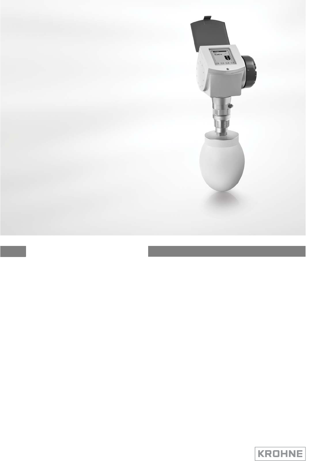
Non-contact Radar (FMCW) Level Meter
for distance, level and volume measurement of solids
OPTIWAVE 6300 C Handbook
© KROHNE 04/2009 - 4000547001 - HB OPTIWAVE 6300 R01 en

All rights reserved. It is prohibited to reproduce this documentation, or any part thereof, without
the prior written authorisation of KROHNE Messtechnik GmbH & Co. KG.
Subject to change without notice.
2 www.krohne.com 04/2009 - 4000547001 - HB OPTIWAVE 6300 R01 en
Copyright 2009 by
KROHNE Messtechnik GmbH & Co. KG - Ludwig-Krohne-Straße 5 - 47058 Duisburg
: IMPRINT ::::::::::::::::::::::::::::::::::

CONTENTS
3
www.krohne.com04/2009 - 4000547001 - HB OPTIWAVE 6300 R01 en
OPTIWAVE 6300 C
1 Safety instructions 6
1.1 Intended use ..................................................................................................................... 6
1.2 Certification ...................................................................................................................... 6
1.3 Electromagnetic compatibility ......................................................................................... 6
1.4 Radio approvals ................................................................................................................ 7
1.4.1 European Union (EU)............................................................................................................... 7
1.4.2 U.S.A........................................................................................................................................ 8
1.5 Safety instructions from the manufacturer ..................................................................... 8
1.5.1 Copyright and data protection ................................................................................................ 8
1.5.2 Disclaimer ............................................................................................................................... 9
1.5.3 Product liability and warranty ................................................................................................ 9
1.5.4 Information concerning the documentation........................................................................... 9
1.5.5 Warnings and symbols used................................................................................................. 10
1.6 Safety instructions for the operator............................................................................... 10
2 Device description 11
2.1 Scope of delivery............................................................................................................. 11
2.2 Device description .......................................................................................................... 13
2.3 Visual Check ................................................................................................................... 14
2.4 Nameplates .................................................................................................................... 15
2.4.1 Non-Ex nameplate ................................................................................................................ 15
3 Installation 16
3.1 Notes on installation ......................................................................................................16
3.2 Storage ........................................................................................................................... 16
3.3 Transport ........................................................................................................................ 17
3.4 Pre-installation requirements ....................................................................................... 17
3.5 How to prepare the silo before you install the device ................................................... 18
3.5.1 Pressure and temperature ranges....................................................................................... 18
3.5.2 Theoretical data for nozzle position .....................................................................................19
3.6 Installation recommendations for solids....................................................................... 21
3.7 How to install the device on the silo .............................................................................. 22
3.7.1 How to install a device with a flange connection ................................................................. 22
3.7.2 How to install a device with a threaded connection............................................................. 24
3.7.3 How to attach antenna extensions....................................................................................... 26
3.7.4 How to turn or remove the signal converter ........................................................................ 27
3.7.5 How to attach the weather protection to the device............................................................. 28
3.7.6 How to open the weather protection .................................................................................... 29
4 Electrical connections 30
4.1 Safety instructions.......................................................................................................... 30
4.2 Electrical installation: outputs 1 and 2 .......................................................................... 30
4.2.1 Non-Ex................................................................................................................................... 31
4.2.2 Ex i ......................................................................................................................................... 31
4.2.3 Ex d........................................................................................................................................ 31
4.3 Protection category ........................................................................................................32

CONTENTS
4 www.krohne.com 04/2009 - 4000547001 - HB OPTIWAVE 6300 R01 en
OPTIWAVE 6300 C
4.4 Networks ........................................................................................................................ 33
4.4.1 General information.............................................................................................................. 33
4.4.2 Point-to-point connection..................................................................................................... 33
4.4.3 Multi-drop networks ............................................................................................................. 34
5 Start-up 35
5.1 Start-up checklist........................................................................................................... 35
5.2 Operating concept ..........................................................................................................35
5.3 Digital display screen .....................................................................................................36
5.3.1 Local display screen layout .................................................................................................. 36
5.3.2 Push-button functions .......................................................................................................... 36
5.3.3 Help screens ......................................................................................................................... 36
5.3.4 How to start the device ......................................................................................................... 37
5.4 Remote communication with PACTware™ .................................................................... 37
5.5 Remote communication with the AMS™ Device Manager............................................. 38
6 Operation 39
6.1 User modes .................................................................................................................... 39
6.2 Operator mode................................................................................................................ 39
6.3 Supervisor mode ............................................................................................................41
6.3.1 General notes........................................................................................................................ 41
6.3.2 How to get access to the supervisor mode .......................................................................... 41
6.3.3 Menu overview ...................................................................................................................... 42
6.3.4 Push-button functions .......................................................................................................... 43
6.3.5 Function description ............................................................................................................. 46
6.4 Further information on device configuration................................................................. 57
6.4.1 Quick Links............................................................................................................................ 57
6.4.2 Protection of the device settings .......................................................................................... 58
6.4.3 Network configuration .......................................................................................................... 59
6.4.4 Linearisation ......................................................................................................................... 60
6.4.5 Distance measurement ........................................................................................................ 60
6.4.6 Level measurement .............................................................................................................. 61
6.4.7 How to configure the device to measure volume or mass................................................... 63
6.4.8 How to use the empty spectrum function to filter parasite signals.................................... 64
6.4.9 How to measure correctly in silos with curved or conical bottoms..................................... 65
6.5 Service mode .................................................................................................................. 66
6.6 Errors.............................................................................................................................. 67
6.6.1 General information.............................................................................................................. 67
6.6.2 Error handling....................................................................................................................... 70
7 Service 73
7.1 Periodic maintenance..................................................................................................... 73
7.2 How to clean the top surface of the device .................................................................... 73
7.3 How to clean horn antennas under process conditions ................................................ 74
7.4 How to replace device components ............................................................................... 75
7.4.1 Service warranty ................................................................................................................... 75
7.4.2 Replacement of the display cover.........................................................................................76
7.4.3 Replacement of the back end and microwave unit .............................................................. 78

CONTENTS
5
www.krohne.com04/2009 - 4000547001 - HB OPTIWAVE 6300 R01 en
OPTIWAVE 6300 C
7.4.4 Replacement of the terminal module................................................................................... 80
7.5 Spare parts availability...................................................................................................82
7.5.1 List of spare parts................................................................................................................. 82
7.5.2 List of accessories ................................................................................................................ 84
7.6 Availability of services .................................................................................................... 86
7.7 Returning the device to the manufacturer..................................................................... 86
7.7.1 General information.............................................................................................................. 86
7.7.2 Form (for copying) to accompany a returned device............................................................ 87
7.8 Disposal .......................................................................................................................... 87
8 Technical data 88
8.1 Measuring principle........................................................................................................88
8.2 Technical data................................................................................................................. 89
8.3 Antenna selection........................................................................................................... 93
8.4 Dimensions and weights ................................................................................................ 94
9 Appendix 100
9.1 Order form.................................................................................................................... 100
9.1.1 Device data.......................................................................................................................... 100
9.1.2 Rating data .......................................................................................................................... 100
9.1.3 Contact data ........................................................................................................................ 100
9.2 Glossary ........................................................................................................................ 101
1 SAFETY INSTRUCTIONS
6
OPTIWAVE 6300 C
www.krohne.com 04/2009 - 4000547001 - HB OPTIWAVE 6300 R01 en
1.1 Intended use
This radar level transmitter measures distance, level, mass, volume and reflectivity of
granulates and powders.
It can be installed on silos and bunkers.
1.2 Certification
In accordance with the commitment to customer service and safety, the device
described in this document meets the following safety requirements:
•EMC Directive 2004 / 108 / EC and 93 / 68 / EEC in conjunction with EN 61326-1 (2006).
•Low-Voltage Directives 2006 / 95 / EC and 93 / 68 / EEC in conjunction with
EN 61010-1 (2001).
All devices are based on the CE marking and meet the requirements of NAMUR Guideline
NE 21 / 04.
1.3 Electromagnetic compatibility
The device design agrees with European Standard EN 61326-1.
You can install the device on open-air tanks and tanks that are not made of metal. But refer to
Radio approvals
on page 7. This agrees with Immunity and Emissions requirements for industrial
environments.
DANGER!
For devices used in hazardous areas, additional safety notes apply; please refer to the Ex
documentation.
INFORMATION!
Device operation agrees with residential-class (class B) immunity and emissions requirements if
the antenna is used in a closed silo made of metal.
SAFETY INSTRUCTIONS 1
7
OPTIWAVE 6300 C
www.krohne.com04/2009 - 4000547001 - HB OPTIWAVE 6300 R01 en
1.4 Radio approvals
1.4.1 European Union (EU)
According to EN 300 440 (2001-09), the radiated power outside a metallic silo is less than
-30 dBm.
Refer also to the radio approval certificate on the internet site. The radio approval report is given
on the CD-ROM supplied with the device.
LEGAL NOTICE!
This level transmitter is intended for installation in closed metallic tanks. It
meets the requirements of the R & TTE (Radio Equipment and Telecommunications Terminal
Equipment)
Directive 1999/05/EC for use in the member countries of the EU.
The device operates using a frequency band (24 GHz - 26 GHz) that is not harmonized within the
EU.
According to article 6.4 of the R&TTE Directive, the product is marked by the CE sign + notified
body number (0682) + Class II identifier (= alert sign).
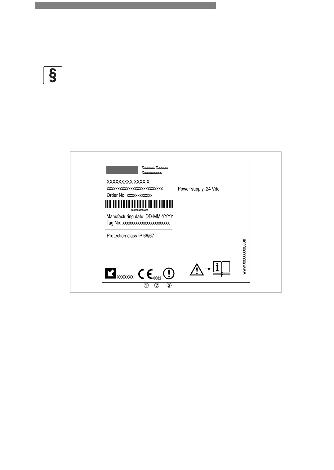
Figure 1-1: Radio approval information on the nameplate
1 CE sign
2 Notified body number (0682 = CETECOM)
3 Class II identifier

1 SAFETY INSTRUCTIONS
8
OPTIWAVE 6300 C
www.krohne.com 04/2009 - 4000547001 - HB OPTIWAVE 6300 R01 en
1.4.2 U.S.A.
This legal information is shown on a label on the rear side of the device.
The radio approval report is given on the CD-ROM supplied with the device. You can also
download it from the internet site.
1.5 Safety instructions from the manufacturer
1.5.1 Copyright and data protection
The contents of this document have been created with great care. Nevertheless, we provide no
guarantee that the contents are correct, complete or up-to-date.
The contents and works in this document are subject to German copyright. Contributions from
third parties are identified as such. Reproduction, processing, dissemination and any type of use
beyond what is permitted under copyright requires written authorisation from the respective
author and/or the manufacturer.
The manufacturer tries always to observe the copyrights of others, and to draw on works created
in-house or works in the public domain.
The collection of personal data (such as names, street addresses or e-mail addresses) in the
manufacturer's documents is always on a voluntary basis whenever possible. Whenever
feasible, it is always possible to make use of the offerings and services without providing any
personal data.
We draw your attention to the fact that data transmission over the Internet (e.g. when
communicating by e-mail) may involve gaps in security. It is not possible to protect such data
completely against access by third parties.
We hereby expressly prohibit the use of the contact data published as part of our duty to publish
an imprint for the purpose of sending us any advertising or informational materials that we have
not expressly requested.
LEGAL NOTICE!
This device complies with Part 15 of the FCC Rules. Operation is subject to the following two
conditions:
1. This device may not cause harmful interference, and
2. this device must accept any interference received, including interference which may cause un-
desired operation.

SAFETY INSTRUCTIONS 1
9
OPTIWAVE 6300 C
www.krohne.com04/2009 - 4000547001 - HB OPTIWAVE 6300 R01 en
1.5.2 Disclaimer
The manufacturer will not be liable for any damage of any kind by using its product, including,
but not limited to direct, indirect, incidental, punitive and consequential damages.
This disclaimer does not apply in case the manufacturer has acted on purpose or with gross
negligence. In the event any applicable law does not allow such limitations on implied warranties
or the exclusion of limitation of certain damages, you may, if such law applies to you, not be
subject to some or all of the above disclaimer, exclusions or limitations.
Any product purchased from the manufacturer is warranted in accordance with the relevant
product documentation and our Terms and Conditions of Sale.
The manufacturer reserves the right to alter the content of its documents, including this
disclaimer in any way, at any time, for any reason, without prior notification, and will not be liable
in any way for possible consequences of such changes.
1.5.3 Product liability and warranty
The operator shall bear responsibility for the suitability of the device for the specific purpose.
The manufacturer accepts no liability for the consequences of misuse by the operator. Improper
installation and operation of the devices (systems) will cause the warranty to be void. The
respective "Standard Terms and Conditions" which form the basis for the sales contract shall
also apply.
1.5.4 Information concerning the documentation
To prevent any injury to the user or damage to the device it is essential that you read the
information in this document and observe applicable national standards, safety requirements
and accident prevention regulations.
If this document is not in your native language and if you have any problems understanding the
text, we advise you to contact your local office for assistance. The manufacturer can not accept
responsibility for any damage or injury caused by misunderstanding of the information in this
document.
This document is provided to help you establish operating conditions, which will permit safe and
efficient use of this device. Special considerations and precautions are also described in the
document, which appear in the form of underneath icons.
1 SAFETY INSTRUCTIONS
10
OPTIWAVE 6300 C
www.krohne.com 04/2009 - 4000547001 - HB OPTIWAVE 6300 R01 en
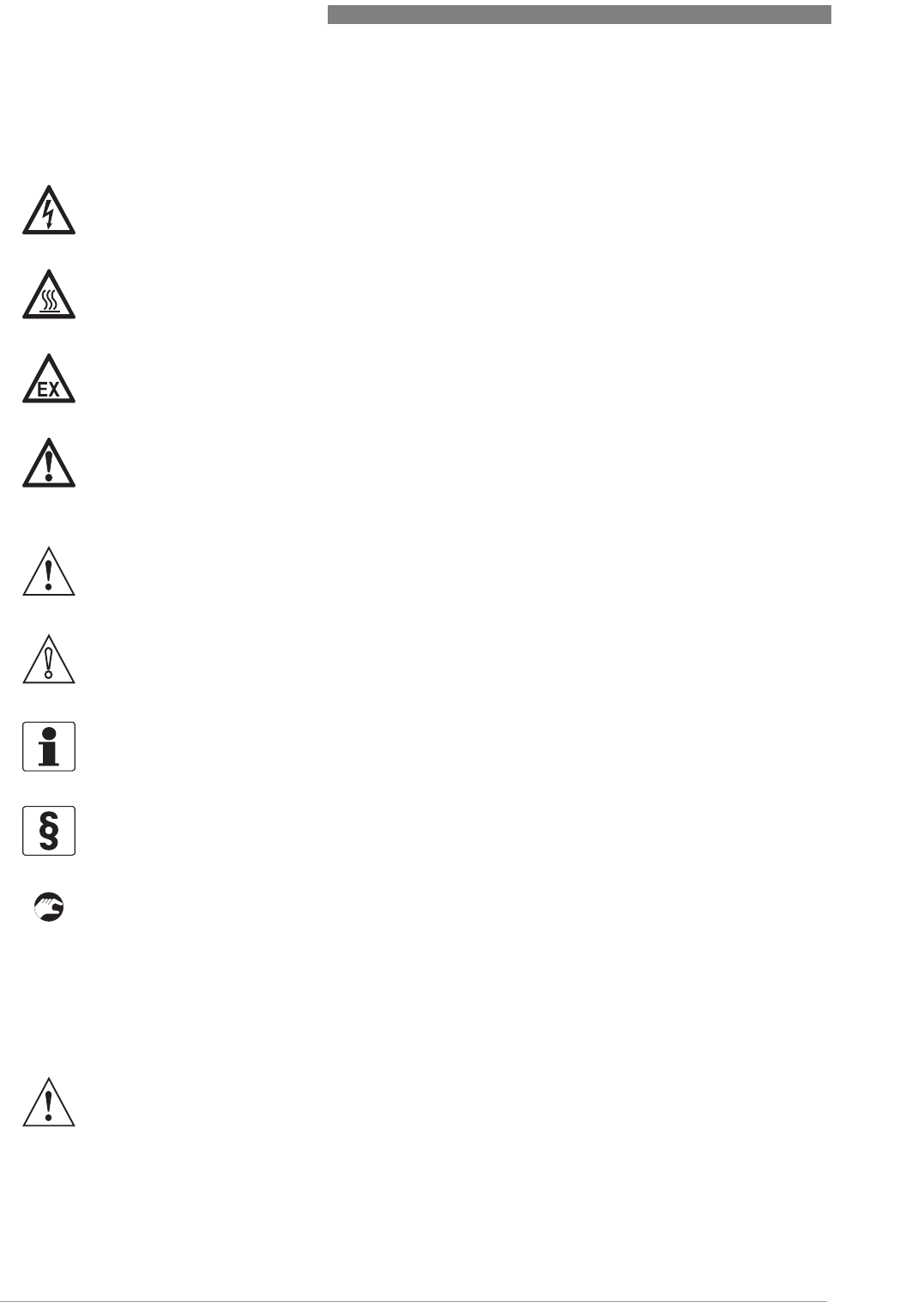
1.5.5 Warnings and symbols used
Safety warnings are indicated by the following symbols.
• HANDLING
This symbol designates all instructions for actions to be carried out by the operator in the
specified sequence.
iRESULT
This symbol refers to all important consequences of the previous actions.
1.6 Safety instructions for the operator
DANGER!
This information refers to the immediate danger when working with electricity.
DANGER!
This warning refers to the immediate danger of burns caused by heat or hot surfaces.
DANGER!
This warning refers to the immediate danger when using this device in a hazardous atmosphere.
DANGER!
These warnings must be observed without fail. Even partial disregard of this warning can lead to
serious health problems and even death. There is also the risk of seriously damaging the device
or parts of the operator's plant.
WARNING!
Disregarding this safety warning, even if only in part, poses the risk of serious health problems.
There is also the risk of damaging the device or parts of the operator's plant.
CAUTION!
Disregarding these instructions can result in damage to the device or to parts of the operator's
plant.
INFORMATION!
These instructions contain important information for the handling of the device.
LEGAL NOTICE!
This note contains information on statutory directives and standards.
WARNING!
In general, devices from the manufacturer may only be installed, commissioned, operated and
maintained by properly trained and authorized personnel.
This document is provided to help you establish operating conditions, which will permit safe and
efficient use of this device.
DEVICE DESCRIPTION 2
11
OPTIWAVE 6300 C
www.krohne.com04/2009 - 4000547001 - HB OPTIWAVE 6300 R01 en
2.1 Scope of delivery
INFORMATION!
Inspect the cartons carefully for damage or signs of rough handling. Report damage to the
carrier and to the local office of the manufacturer.
INFORMATION!
Check the packing list to check if you received completely all that you ordered.
INFORMATION!
Look at the device nameplate to ensure that the device is delivered according to your order.
Check for the correct supply voltage printed on the nameplate.
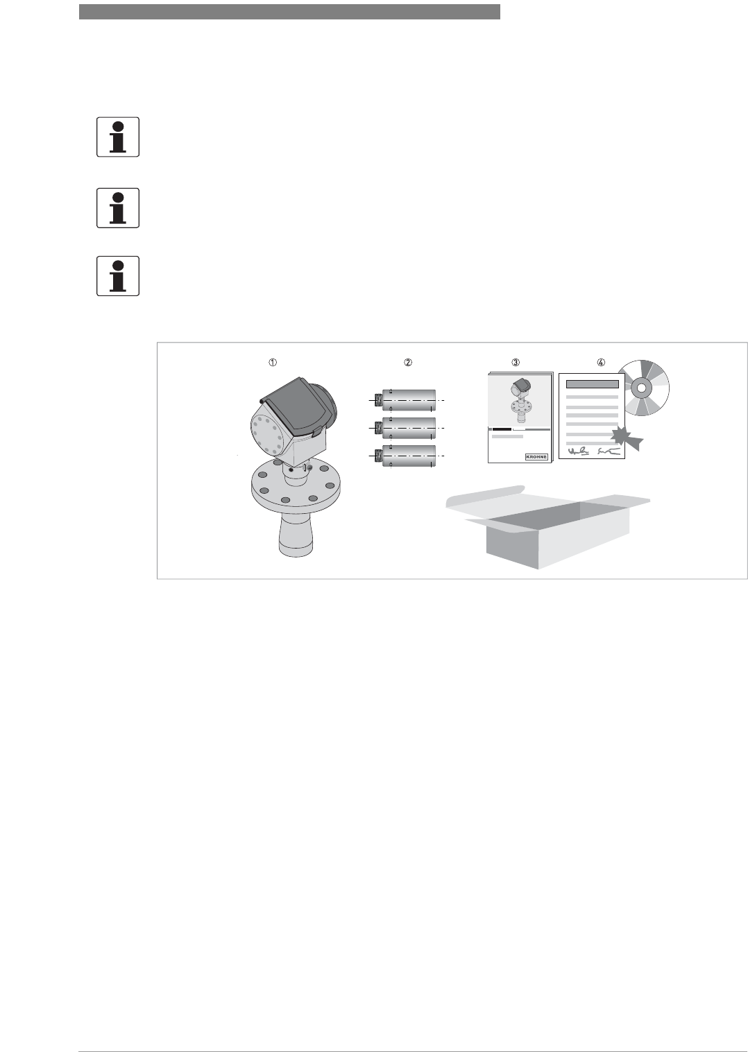
Scope of delivery - horn antenna
Figure 2-1: Scope of delivery - horn antenna
1 Signal converter and antenna in compact version
2 Antenna extensions (option)
3 Quick Start
4 CD-ROM (including Handbook, Quick Start, Technical Datasheet and related software)
2 DEVICE DESCRIPTION
12
OPTIWAVE 6300 C
www.krohne.com 04/2009 - 4000547001 - HB OPTIWAVE 6300 R01 en
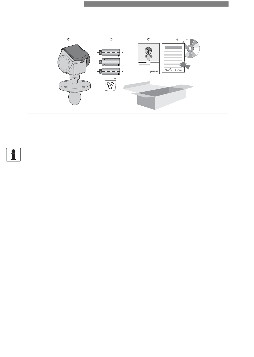
Scope of delivery - Drop antenna
Figure 2-2: Scope of delivery - Drop antenna
1 Signal converter and antenna in compact version
2 Antenna extensions (option) and o-ring for each antenna extension
3 Quick Start
4 CD-ROM (including Handbook, Quick Start, Technical Datasheet, and related software)
INFORMATION!
No special tools or training required!

DEVICE DESCRIPTION 2
13
OPTIWAVE 6300 C
www.krohne.com04/2009 - 4000547001 - HB OPTIWAVE 6300 R01 en
2.2 Device description
This device is a 24 GHz FMCW-radar level transmitter. It is a non-contact technology and is 2-
wire loop-powered. It is designed to measure the distance, level, mass, volume and reflectivity
of granulates and powders.
Radar level transmitters use an antenna to guide a signal to the surface of the measured
product. The device has many antennas available. Thus, it can measure most products even in
difficult conditions. Also refer to
Technical data
on page 88.
The device has a setup wizard, fully-potted electronic circuit boards and online help functions. It
has a 4...20 mA+HART output (a second output is optional) and an optional local display. You
usually will not need this Handbook to install, setup and operate the device.
If it is ordered with the applicable options, it can be certified for use in hazardous areas.
These accessories are available:
•stainless steel weather protection.
•RS232/HART® converter (VIATOR).
•USB/HART® converter.
•2° PP slanted flange
INFORMATION!
For more data on accessories, refer to List of accessories on page 84
.
2 DEVICE DESCRIPTION
14
OPTIWAVE 6300 C
www.krohne.com 04/2009 - 4000547001 - HB OPTIWAVE 6300 R01 en
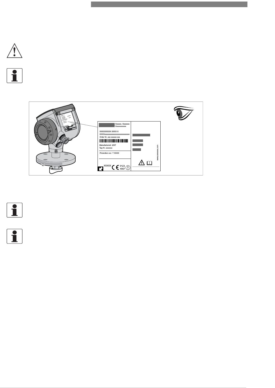
2.3 Visual Check
WARNING!
If the display screen glass is broken, do not touch.
INFORMATION!
Inspect the cartons carefully for damage or signs of rough handling. Report damage to the
carrier and to the local office of the manufacturer.
Figure 2-3: Visual check
1 Device nameplate (for more data, refer to
Non-Ex nameplate
on page 15)
2 Process connection data (size and pressure rating, material reference and heat number)
1
INFORMATION!
Look at the device nameplate to ensure that the device is delivered according to your order.
Check for the correct supply voltage printed on the nameplate.
INFORMATION!
Compare the material reference on the side of the process connection with the order.
DEVICE DESCRIPTION 2
15
OPTIWAVE 6300 C
www.krohne.com04/2009 - 4000547001 - HB OPTIWAVE 6300 R01 en
2.4 Nameplates
2.4.1 Non-Ex nameplate
INFORMATION!
Look at the device nameplate to ensure that the device is delivered according to your order.
Check for the correct supply voltage printed on the nameplate.
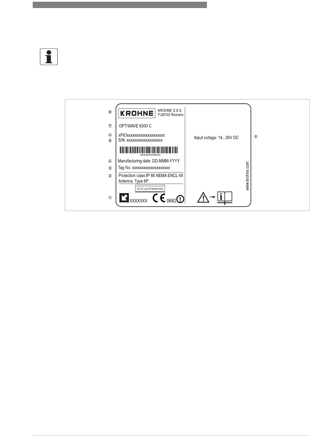
Figure 2-4: Non-Ex nameplate
1 Indicator arrow to cable entry / cable entry size. Notified body for radio approval.
2 Degree of ingress protection (according to EN 60529 / IEC 529)
3 Customer tag number
4 Date of manufacture
5 Order number
6 Type code (defined in order)
7 Model name and number
8 Company name and address
9 Nominal voltage for operation. For further information, refer to
Non-Ex
on page 31.
3 INSTALLATION
16
OPTIWAVE 6300 C
www.krohne.com 04/2009 - 4000547001 - HB OPTIWAVE 6300 R01 en
3.1 Notes on installation
3.2 Storage
•Store the device in a dry and dust-free location.
•Keep the converter out of the sunlight.
•Store the device in its original packing.
INFORMATION!
Inspect the cartons carefully for damage or signs of rough handling. Report damage to the
carrier and to the local office of the manufacturer.
INFORMATION!
Check the packing list to check if you received completely all that you ordered.
INFORMATION!
Look at the device nameplate to ensure that the device is delivered according to your order.
Check for the correct supply voltage printed on the nameplate.
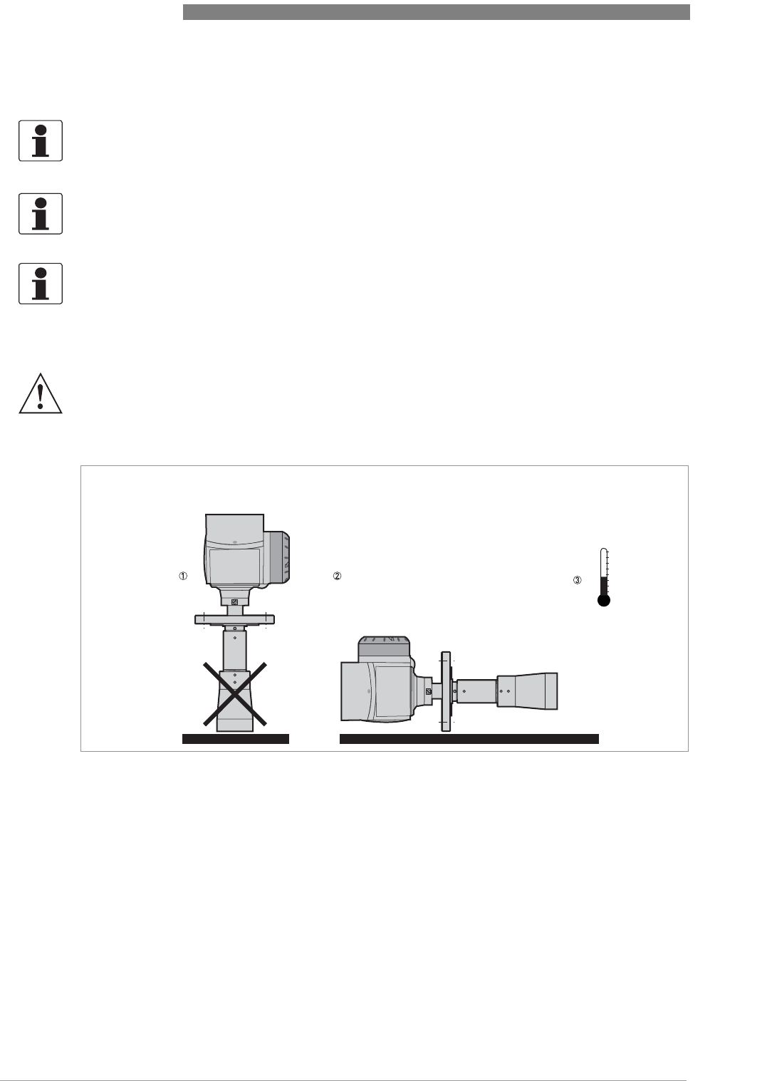
WARNING!
Do not keep the device in a vertical position. This will damage the antenna and the device will not
measure correctly.
Figure 3-1: Storage conditions
1 When you put the device into storage, do not keep it in a vertical position
2 Put the device on its side. We recommend that you use the packaging in which it was delivered.
3 Storage temperature range: -40...+85°C / -40...+185°F
INSTALLATION 3
17
OPTIWAVE 6300 C
www.krohne.com04/2009 - 4000547001 - HB OPTIWAVE 6300 R01 en
3.3 Transport
3.4 Pre-installation requirements
•Make sure that there is adequate space on all sides.
•Protect the signal converter from direct sunlight and install the weather protection accessory
if necessary.
•Do not subject the signal converter to heavy vibrations. The devices are tested for vibration
and agree with EN 50178 and IEC 60068-2-6.
To make sure that you install the device quickly, easily and safely, prepare the installation as
given in the instructions that follow.
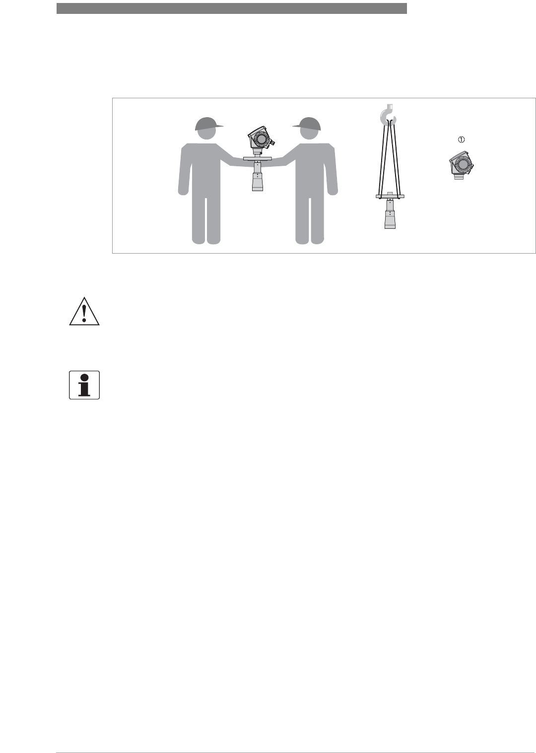
Figure 3-2: How to lift the device
1 Remove the converter before you lift the device with a hoist.
WARNING!
Lift the device carefully to prevent damage to the antenna.
INFORMATION!
The following precautions must be taken to make sure it is correctly installed.
3 INSTALLATION
18
OPTIWAVE 6300 C
www.krohne.com 04/2009 - 4000547001 - HB OPTIWAVE 6300 R01 en
3.5 How to prepare the silo before you install the device
3.5.1 Pressure and temperature ranges
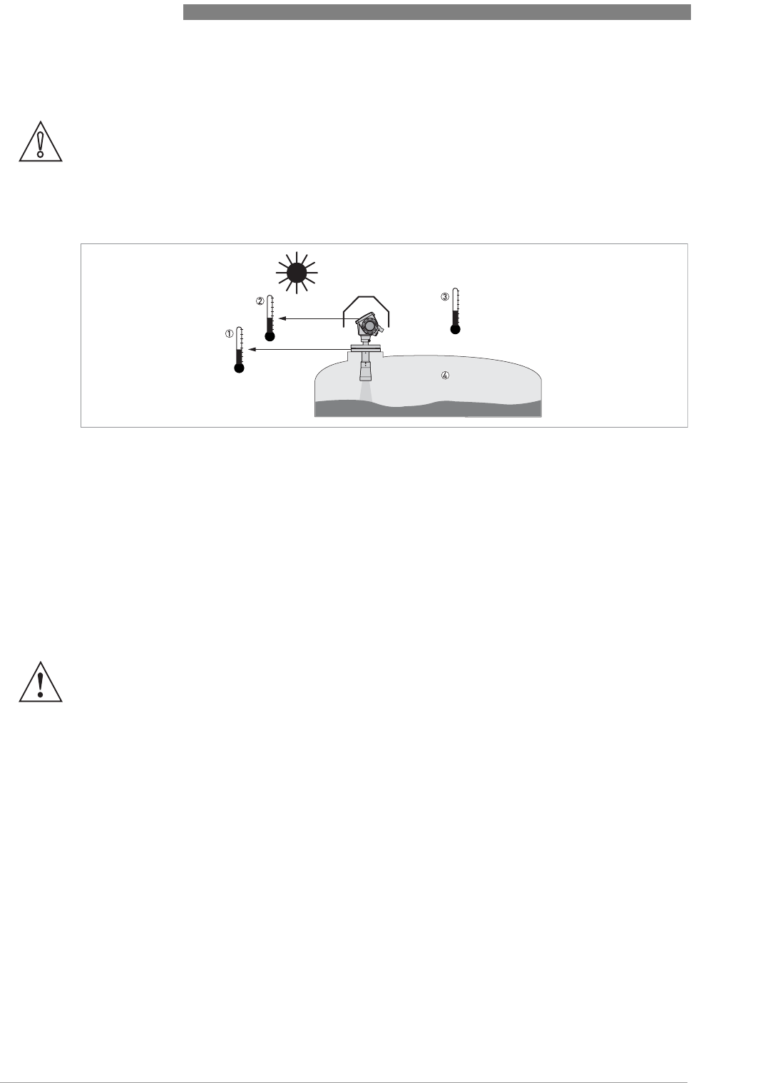
CAUTION!
To avoid measuring errors and device malfunction, obey these precautions.
Figure 3-3: Pressure and temperature ranges
1 Flange temperature
FKM/FPM gasket: -40...200°C / -40...390°F; Kalrez® 6375 gasket: -20...200°C / -4...390°F;
EPDM gasket: -40...+150°C / -40...+300°F
Ex devices: see supplementary operating instructions
2 Ambient temperature for operation of the display
-20...+60°C / -4...+140°F
If the ambient temperature is not between these limits, the display screen switches off automatically
3 Ambient temperature
Non-Ex devices: -40...80°C / -40...175°F
Ex devices: see supplementary operating instructions
4 Process pressure
PP Drop antenna option: -1...16 bar / -14.5...232 psig
All other antenna options: -1...40 bar / -14.5...580 psig
WARNING!
Maximum process connection temperature:
PTFE Drop antenna option: +150
°
C / +300
°
F
PP Drop antenna option: +100
°
C / 210
°
F
INSTALLATION 3
19
OPTIWAVE 6300 C
www.krohne.com04/2009 - 4000547001 - HB OPTIWAVE 6300 R01 en
3.5.2 Theoretical data for nozzle position
CAUTION!
Follow these recommendations to make sure that the device measures correctly.
Figure 3-4: Recommended nozzle position for solids
1 Position of the process fitting from the silo wall, r/2 (for DN80 or DN100 Horn antennas, and DN80 or DN150 Drop
antennas)
2 Radius of the silo, r
3 The minimum measured level for a device without a 2° slanted PP flange option
4 The minimum measured level for a device with a 2° slanted PP flange option
INFORMATION!
If possible, do not install a nozzle on the silo centerline.
INFORMATION!
If it is necessary to measure to the bottom of the silo, a 2
°
slanted flange option is available for
all antennas. For more data, refer to Installation recommendations for solids on page 21
.
CAUTION!
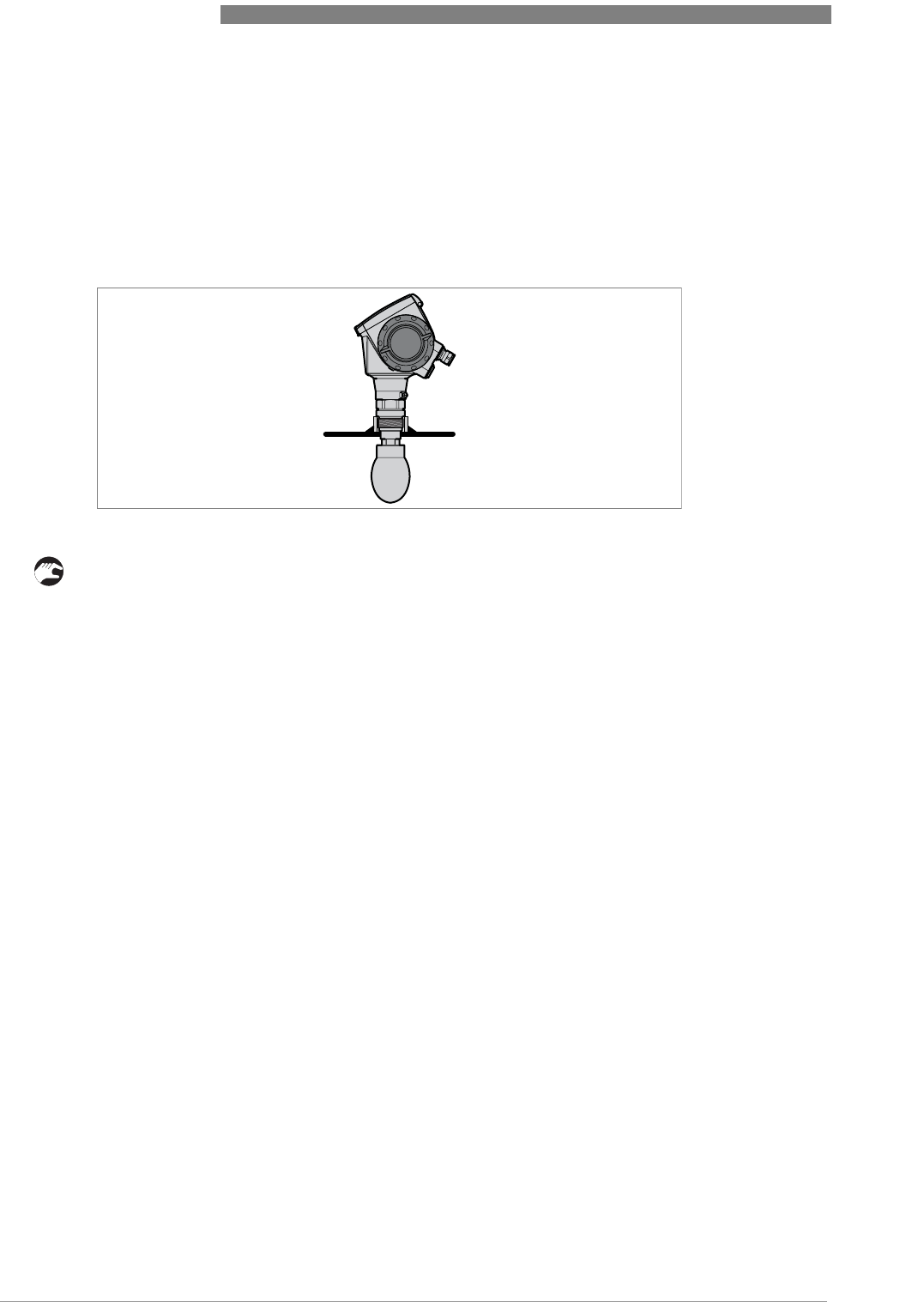
Do not put the device near to the product inlet. If the product that enters the silo touches the
antenna, the device will measure incorrectly. If the product fills the silo directly below the
antenna, the device will also measure incorrectly.
3 INSTALLATION
20
OPTIWAVE 6300 C
www.krohne.com 04/2009 - 4000547001 - HB OPTIWAVE 6300 R01 en
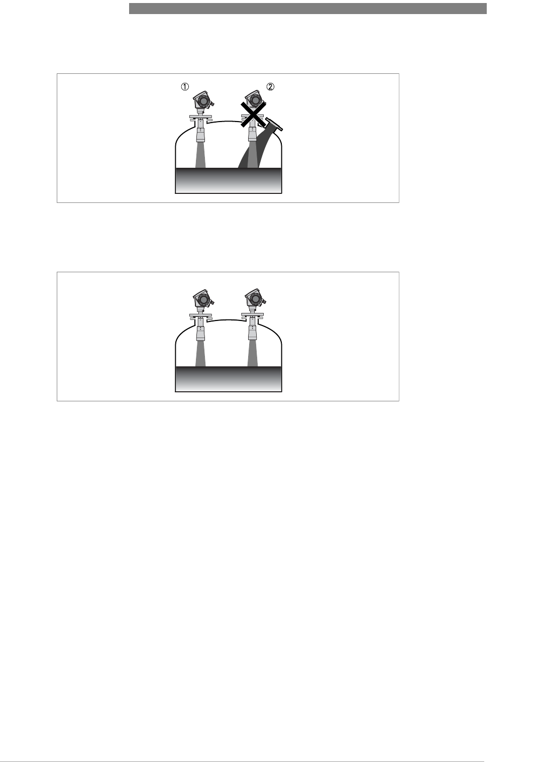
More than 1 FMCW radar level meter can be operated in a silo.
Figure 3-5: Product inlets
1 The device is in the correct position.
2 The device is too near to the product inlet.
Figure 3-6: More than 1 FMCW radar level meter can be operated in a silo
INSTALLATION 3
21
OPTIWAVE 6300 C
www.krohne.com04/2009 - 4000547001 - HB OPTIWAVE 6300 R01 en
3.6 Installation recommendations for solids
CAUTION!
Do not install the device above objects in the silo (ladder, supports etc.). Objects in the silo can
cause parasite radar signals. If there are parasite radar signals, the device will not measure
correctly.
If it is not possible to install the device on another part of the silo, do an empty spectrum scan.
INFORMATION!
We recommend that you configure the device when the silo is empty.
INFORMATION!
For the best device performance, the antenna should be silo-intrusive. Refer to the illustration
that follows.
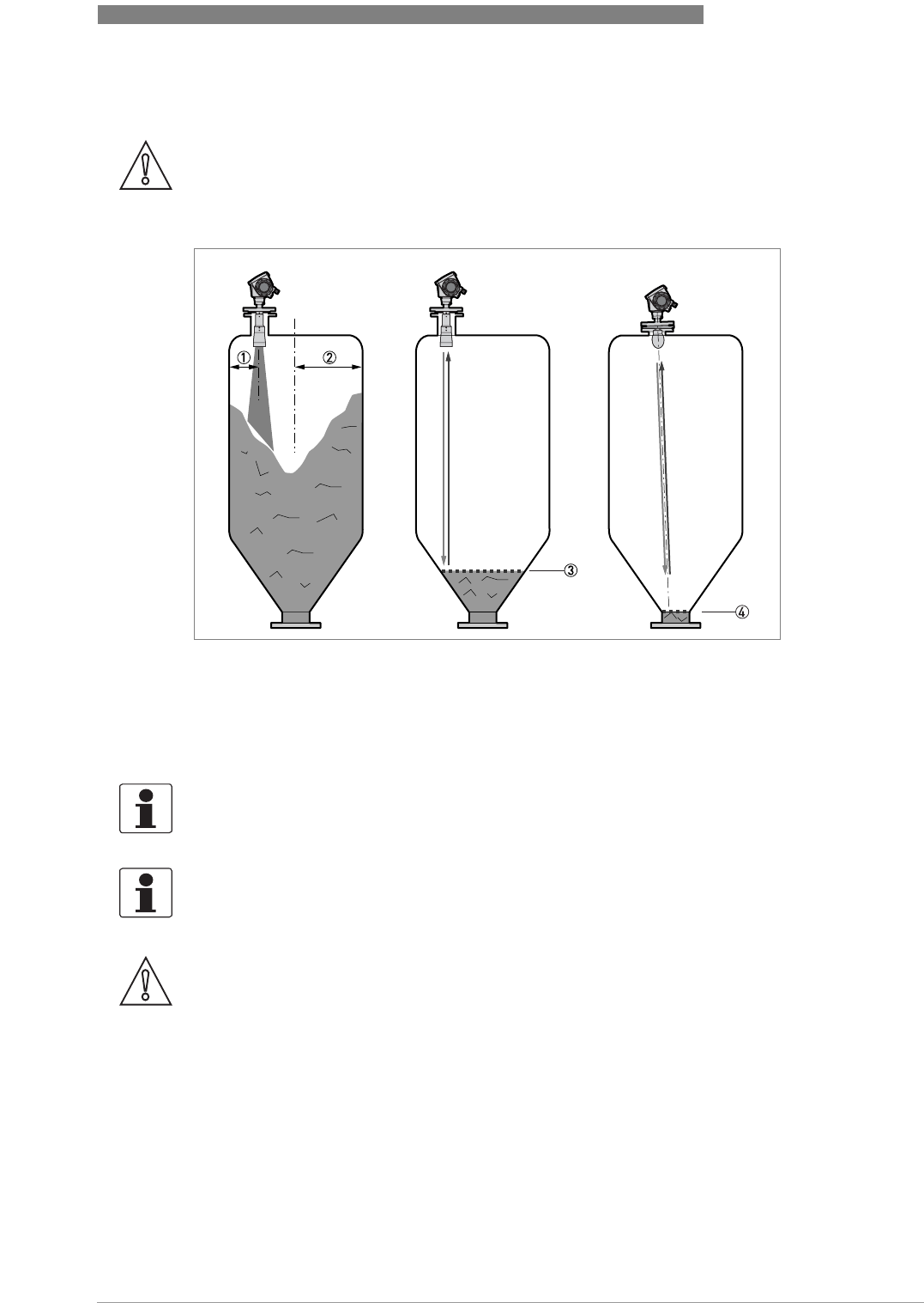
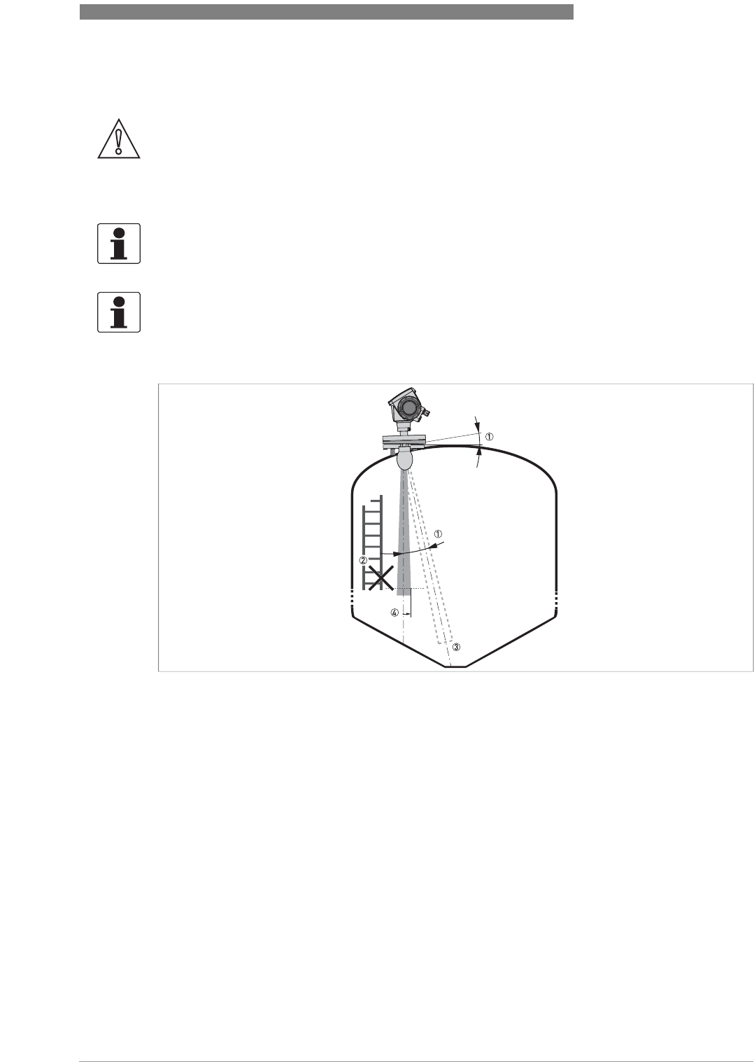
Figure 3-7: General installation recommendations
1 The level transmitter can continue to measure to the bottom of the silo if you tilt the device as shown in the illustration
(a 2° slanted flange option is available for all antennas)
2 If there are too many objects in the radar footprint, do an empty spectrum scan. For more data, refer to
How to use
the empty spectrum function to filter parasite signals
on page 64.
3 Conical silo bottoms. For fine adjustment of the device, refer to
How to measure correctly in silos with curved or con-
ical bottoms
on page 65.
4 Radius of radar footprint (DN80 horn antenna): increments of 90 mm/m or 1.1¨/ft (5°)
Radius of radar footprint (DN100 horn antenna and DN80 Drop antenna): increments of 70 mm/m or 0.83¨/ft (4°)
Radius of radar footprint (DN150 Drop antenna): increments of 35 mm/m or 0.42¨/ft (2°)
3 INSTALLATION
22
OPTIWAVE 6300 C
www.krohne.com 04/2009 - 4000547001 - HB OPTIWAVE 6300 R01 en
3.7 How to install the device on the silo
3.7.1 How to install a device with a flange connection
Equipment needed:
•Device
•Gasket (not supplied)
•Nuts and bolts (not supplied)
•Wrench (not supplied)
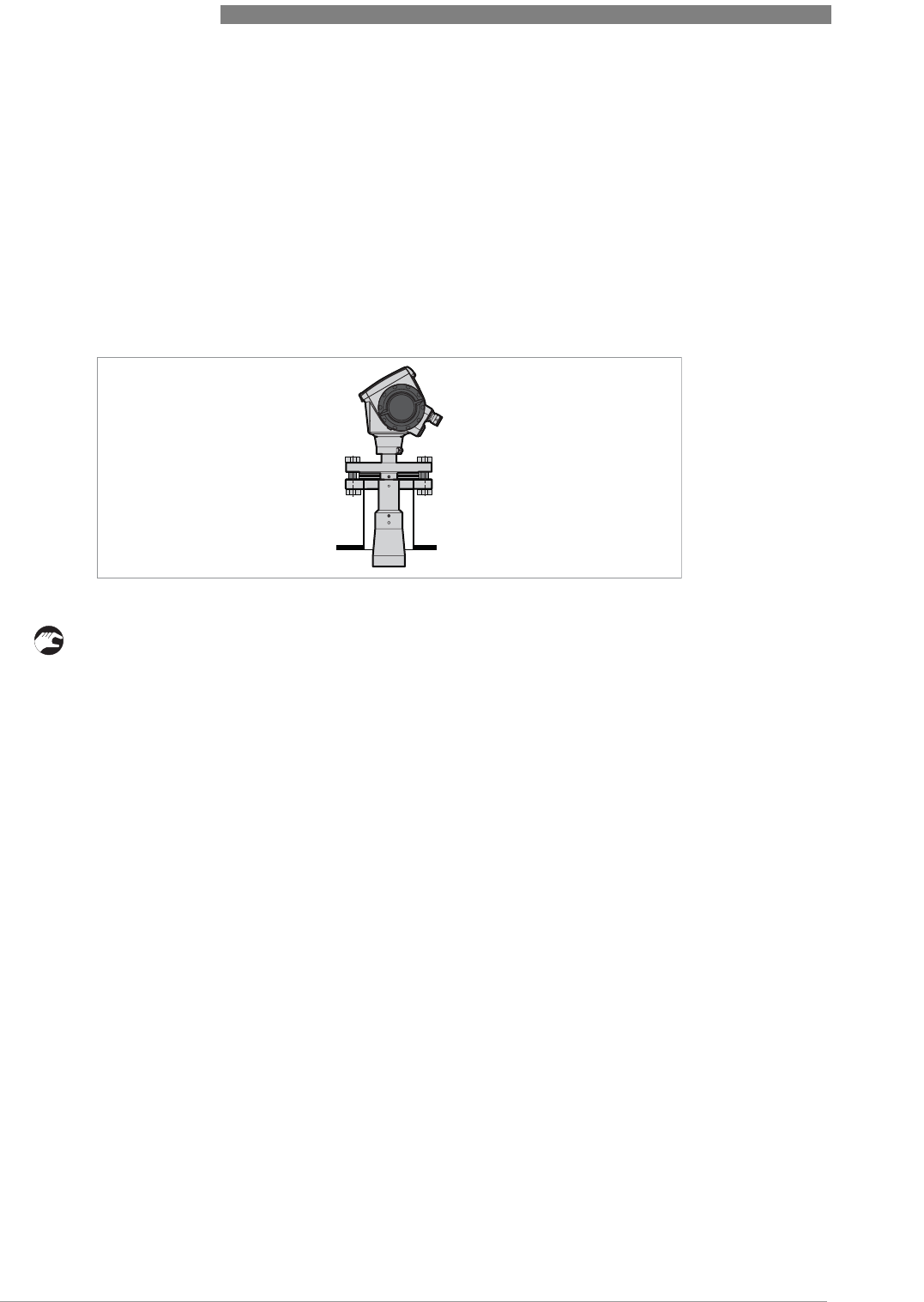
• Make sure the flange on the nozzle is level.
• Make sure that you use the applicable gasket for the flange dimensions and the process.
• Align the gasket correctly on the flange facing of the nozzle.
• Lower the antenna carefully into the silo.
• Tighten the flange bolts.
iRefer to local rules and regulations for the correct torque to apply to the bolts.
Requirements for flange connections
Figure 3-8: Flange connection
INSTALLATION 3
23
OPTIWAVE 6300 C
www.krohne.com04/2009 - 4000547001 - HB OPTIWAVE 6300 R01 en
Equipment needed (not supplied):
•3 mm Allen wrench
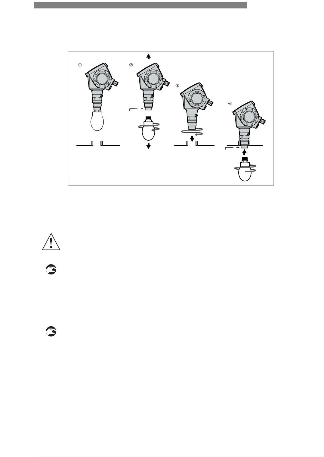
If the process connection is smaller than the antenna:
• Make sure the flange on the nozzle is level.
• Remove the antenna locking screw.
• Remove the antenna from the housing.
• Align the gasket correctly on the flange facing of the nozzle.
• Lower the antenna carefully into the silo. Do not attach to the silo yet.
• Attach the antenna and the antenna locking screw
• Lower the antenna carefully into the silo. Tighten the flange bolts.
• Attach the antenna from inside the silo.
Figure 3-9: How to attach the device if the antenna is smaller than the process connection
WARNING!
If you attach the antenna in a closed space, make sure that there is a good airflow in the area.
Make sure that a person not in the silo can always hear you.
3 INSTALLATION
24
OPTIWAVE 6300 C
www.krohne.com 04/2009 - 4000547001 - HB OPTIWAVE 6300 R01 en
3.7.2 How to install a device with a threaded connection
Equipment needed:
•Device
•Gasket for G 1½ connection (not supplied)
•50 mm / 2¨ wrench (not supplied)
If the process connection is larger than the antenna
• Make sure the silo connection is level.
• Make sure that you use the applicable gasket for the connection dimensions and the process.
• Align the gasket correctly.
• Lower the antenna carefully into the silo.
• Turn the threaded connection on the housing to attach the device to the process connection.
• Tighten the connection.
iRefer to local rules and regulations for the correct torque to apply to the connection.
Requirements for threaded connections
Figure 3-10: Threaded connection
INSTALLATION 3
25
OPTIWAVE 6300 C
www.krohne.com04/2009 - 4000547001 - HB OPTIWAVE 6300 R01 en
Equipment needed (not supplied):
•3 mm Allen wrench
If the process connection is smaller than the antenna:
• Make sure the silo connection is level.
• Remove the antenna locking screw.
• Remove the antenna from the housing.
• Align the gasket correctly. Turn the threaded connection on the housing to attach the device to
the process connection. Tighten the connection.
• Attach the antenna from inside the silo. Attach the antenna locking screw.
If the process connection of the device is smaller than the process connection on the
silo:
• Make sure the silo connection is level.
• Use a plate with a slot or a different applicable procedure to adapt the device to the tank.
• Align the gasket correctly.
• Lower the antenna carefully into the silo.
• If necessary, turn the threaded connection on the housing to attach the device to the plate.
• Tighten the connection.
Figure 3-11: How to attach the device if the antenna is smaller than the process connection
WARNING!
If you attach the antenna in a closed space, make sure that there is a good airflow in the area.
Make sure that a person not in the silo can always hear you.
3 INSTALLATION
26
OPTIWAVE 6300 C
www.krohne.com 04/2009 - 4000547001 - HB OPTIWAVE 6300 R01 en
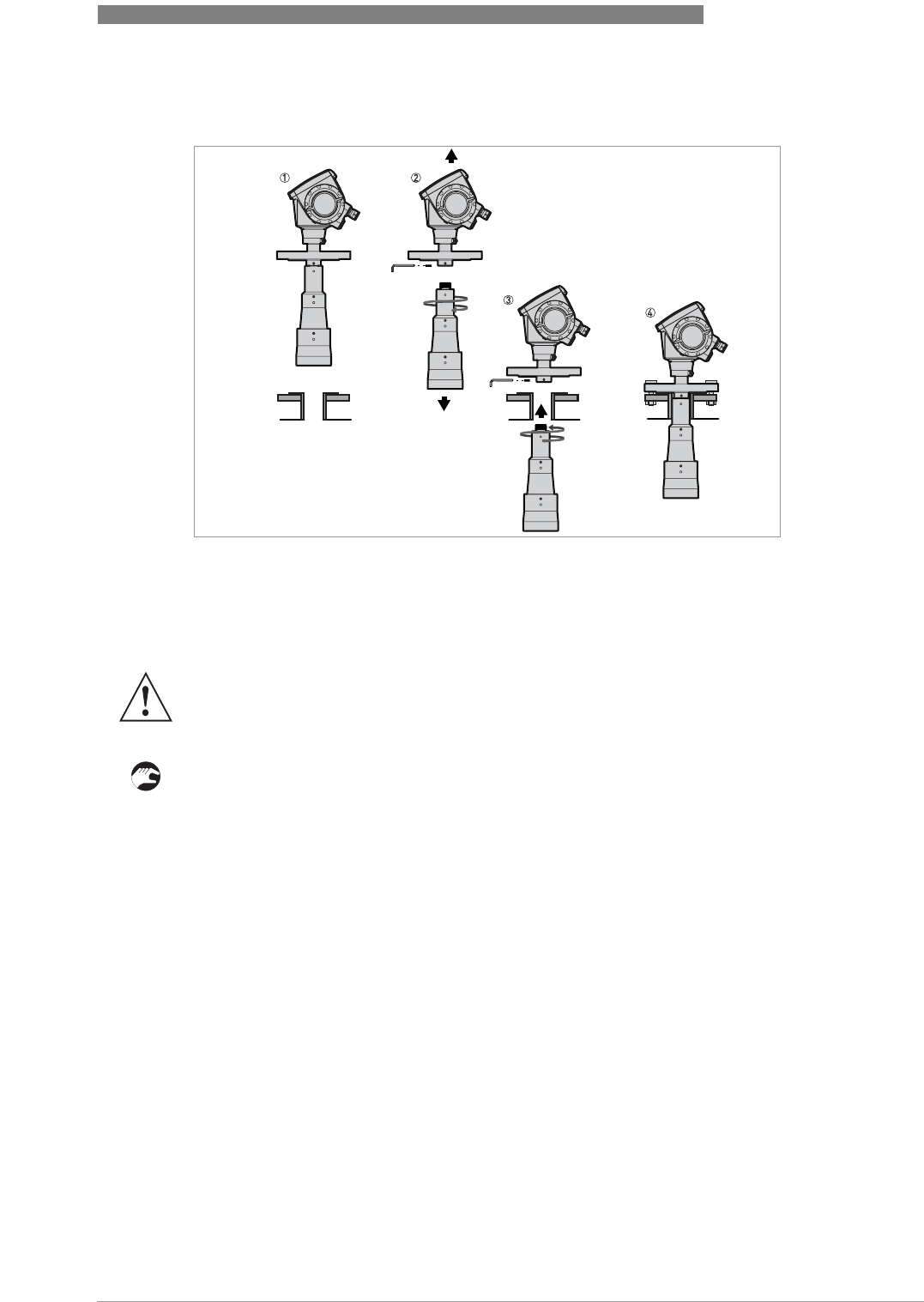
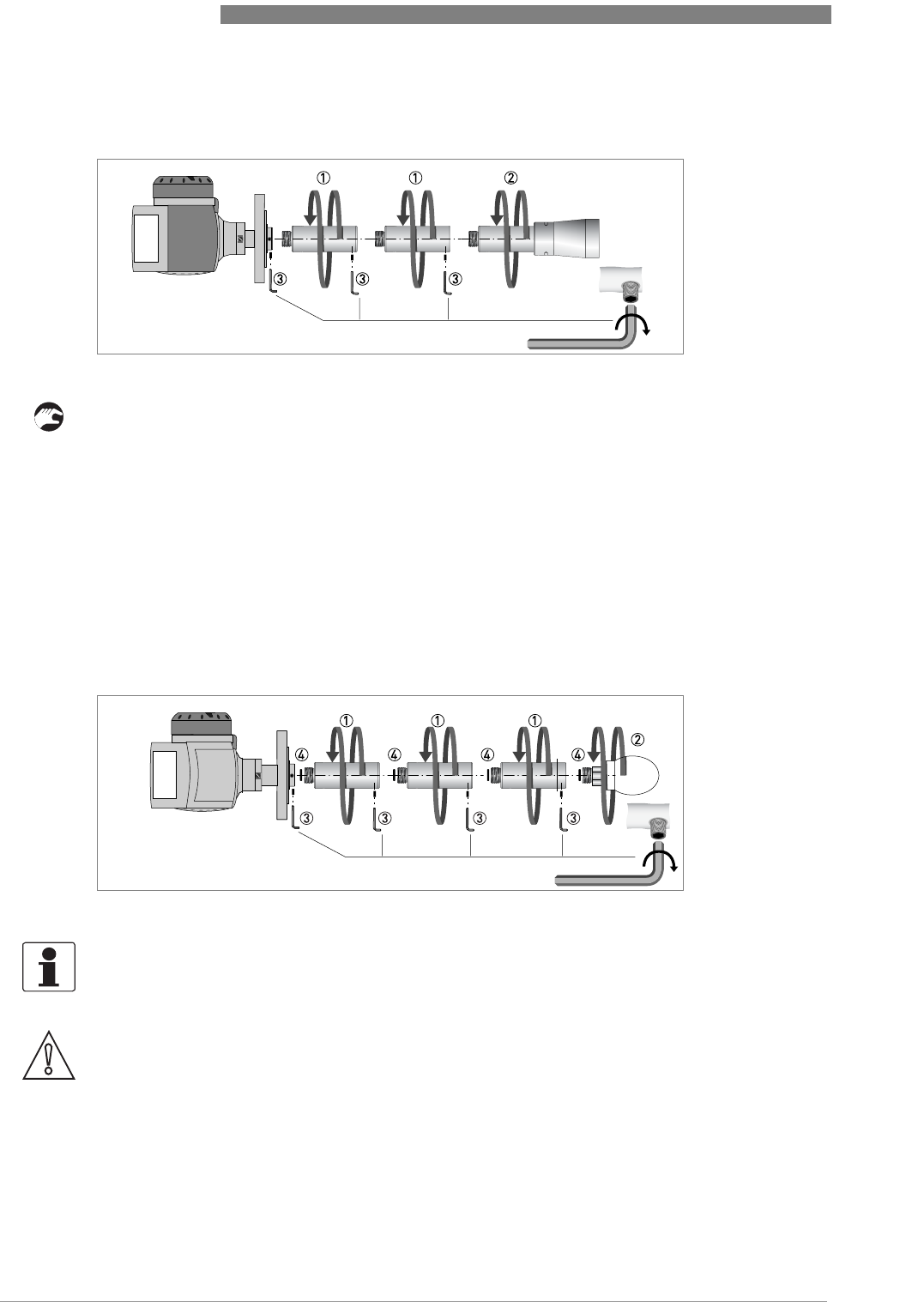
3.7.3 How to attach antenna extensions
• Attach the antenna extensions 1 below the flange.
• Attach the antenna 2.
• Make sure the antenna extensions are fully engaged.
• Use a 3 mm Allen wrench to tighten the locking screws 3.
• If you attach more or less extensions than were initially ordered, change the antenna
extension value in the program mode. Use the display screen or PACTware™.
iAntenna extension = antenna extension length x number of extensions
• If you attach more extensions than were initially ordered, change the blocking distance value
in the user interface.
iMinimum blocking distance = antenna length + (antenna extension length x number of
extensions) + 0.1 m / 4¨
Horn antenna - antenna extensions
Figure 3-12: Horn antenna - how to attach antenna extensions
Drop antenna - antenna extensions
Figure 3-13: Drop antenna - how to attach antenna extensions
INFORMATION!
Drop antenna: Antenna extensions can only be attached below flanges without the PP/PTFE
flange plate option
CAUTION!
Drop antenna: Make sure that there are not more than 5 antenna extensions attached to a device
with a Drop antenna. If there are more than 5 antenna extensions, the device will not measure
correctly.
INSTALLATION 3
27
OPTIWAVE 6300 C
www.krohne.com04/2009 - 4000547001 - HB OPTIWAVE 6300 R01 en
• Remove the o-rings from the plastic sachet supplied with the device. Put an o-ring 4 into the
groove at the top of each antenna extension.
• Attach the antenna extensions 1 below the flange.
• Attach the antenna 2.
• Make sure the antenna extensions are fully engaged.
• Use a 3 mm Allen wrench to tighten the locking screws 3.
• If you attach more or less extensions than were initially ordered, change the antenna
extension value in the program mode. Use the display screen or PACTware™.
iAntenna extension = antenna extension length x number of extensions
• If you attach more extensions than were initially ordered, change the blocking distance value
in the user interface.
iMinimum blocking distance = antenna length + (antenna extension length x number of
extensions) + 0.1 m / 4¨
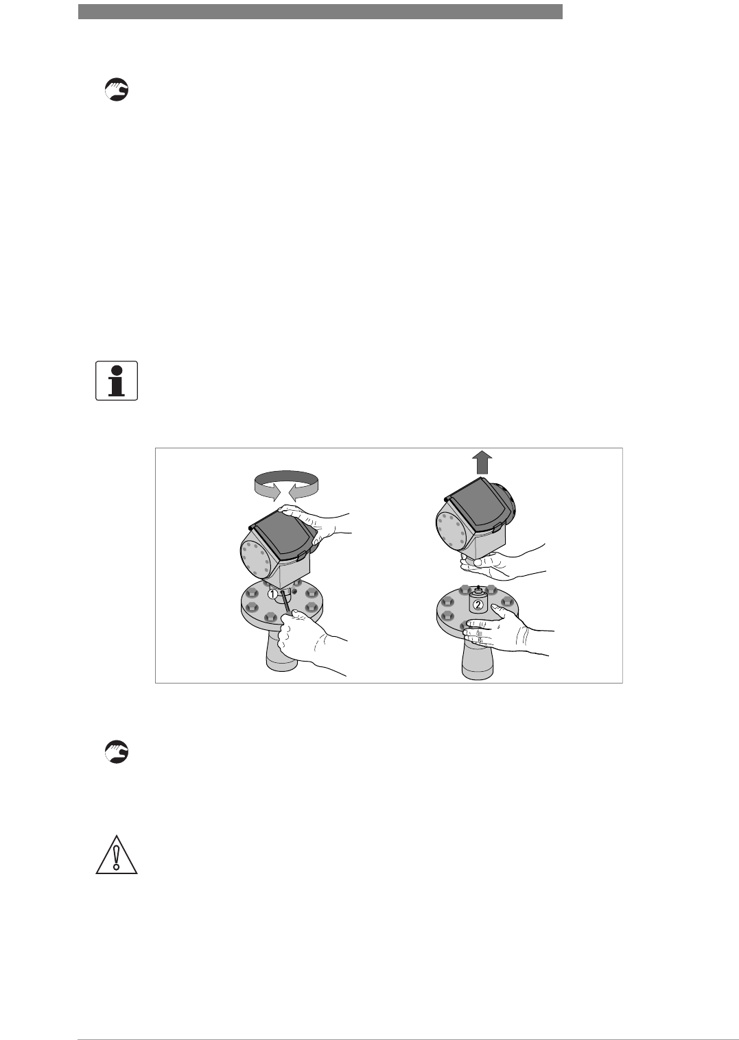
3.7.4 How to turn or remove the signal converter
How to turn the signal converter
• Loosen the housing locking screw 1 with a 5 mm Allen wrench.
• Turn the housing to the correct position.
• Tighten the housing locking screw.
INFORMATION!
The converter turns 360
°
. Remove the signal converter before you lift the device with a hoist.
Figure 3-14: How to turn or remove the signal converter
Tool: 5 mm Allen wrench
CAUTION!
If you remove the housing, put a cover on the wave guide hole in the flange assembly 2.
3 INSTALLATION
28
OPTIWAVE 6300 C
www.krohne.com 04/2009 - 4000547001 - HB OPTIWAVE 6300 R01 en
How to remove the signal converter
• Loosen the housing locking screw 1 with a 5 mm Allen wrench.
• Remove the housing.
• Tighten the housing locking screw 1.
How to attach the signal converter
• Loosen the housing locking screw 1 with a 5 mm Allen wrench.
• Attach the housing to the flange system 2.
• Tighten the housing locking screw 1.
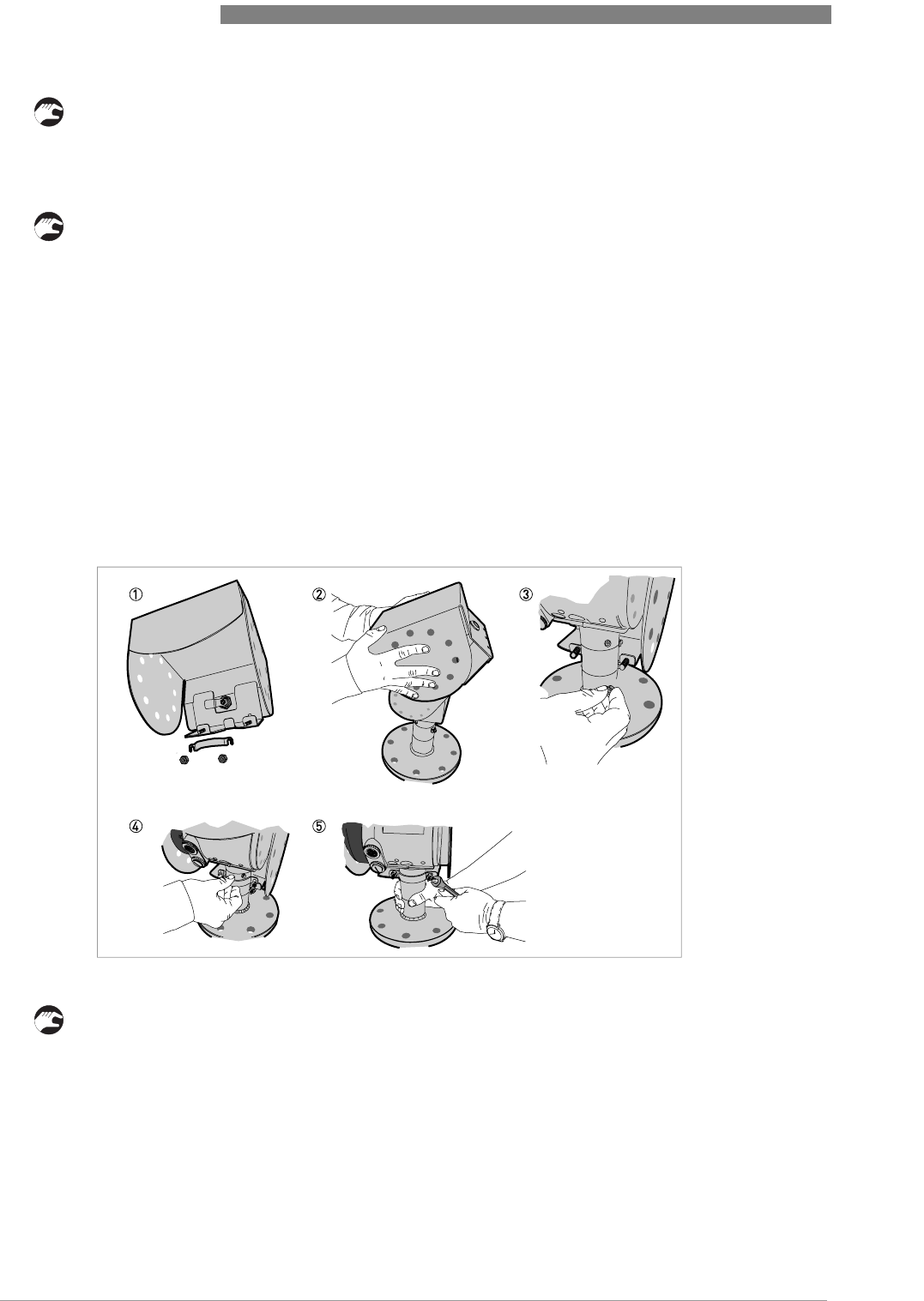
3.7.5 How to attach the weather protection to the device
Equipment needed:
•Device.
•Weather protection (option).
•10 mm wrench (not supplied).
The overall dimensions of the weather protection are on page 94.
• Loosen the bracket nuts on the weather protection.
• Remove the bracket.
• Lower the weather protection onto the device.
• Turn the weather protection so that the keyhole points forward.
• Attach the bracket.
• Lift the weather protection to the top of the housing support pillar.
• Hold the weather protection in the correct position and tighten the bracket nuts.
Figure 3-15: Installation of the weather protection
INSTALLATION 3
29
OPTIWAVE 6300 C
www.krohne.com04/2009 - 4000547001 - HB OPTIWAVE 6300 R01 en
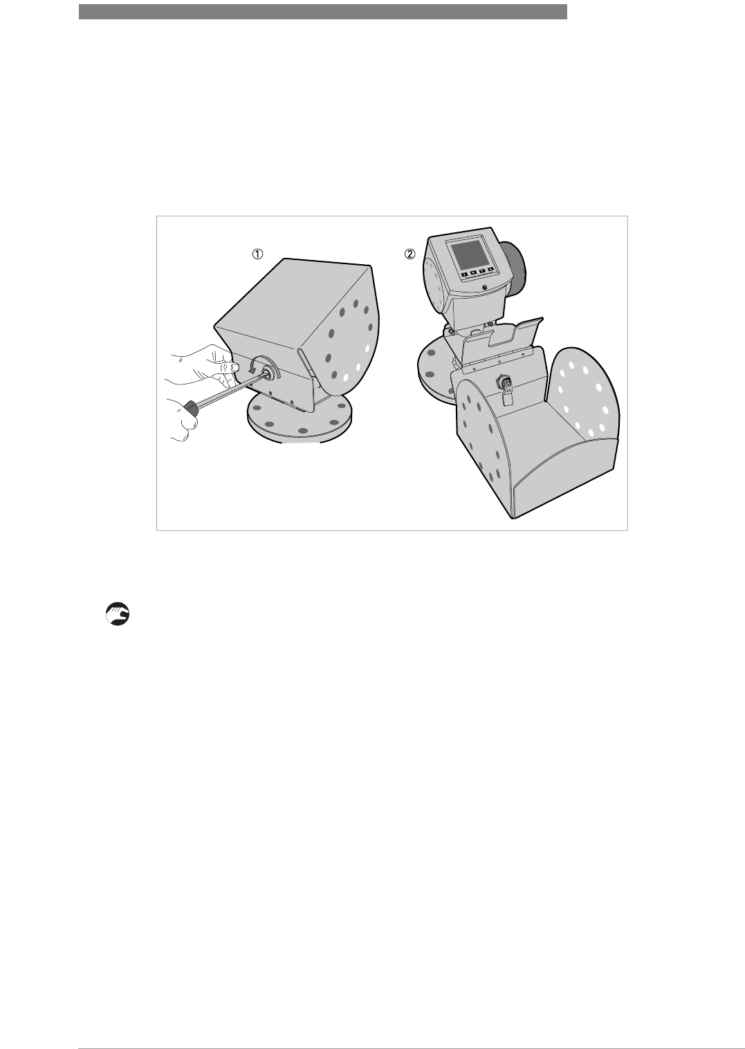
3.7.6 How to open the weather protection
Equipment needed:
•Weather protection.
• Large slotted tip screwdriver (not supplied).
• Put a large slotted tip screwdriver into the keyhole at the front of the weather protection.
• Turn the screwdriver counterclockwise.
• Pull the top of weather protection up and forward.
iThis will open the weather protection.
Figure 3-16: How to open the weather protection
1 Weather protection in its closed position
2 Weather protection in its open position. Minimum clearance in front of the device: 300 mm / 12¨.
4 ELECTRICAL CONNECTIONS
30
OPTIWAVE 6300 C
www.krohne.com 04/2009 - 4000547001 - HB OPTIWAVE 6300 R01 en
4.1 Safety instructions
4.2 Electrical installation: outputs 1 and 2
DANGER!
All work on the electrical connections may only be carried out with the power disconnected. Take
note of the voltage data on the nameplate!
DANGER!
Observe the national regulations for electrical installations!
DANGER!
For devices used in hazardous areas, additional safety notes apply; please refer to the Ex
documentation.
WARNING!
Observe without fail the local occupational health and safety regulations. Any work done on the
electrical components of the measuring device may only be carried out by properly trained
specialists.
INFORMATION!
Look at the device nameplate to ensure that the device is delivered according to your order.
Check for the correct supply voltage printed on the nameplate.
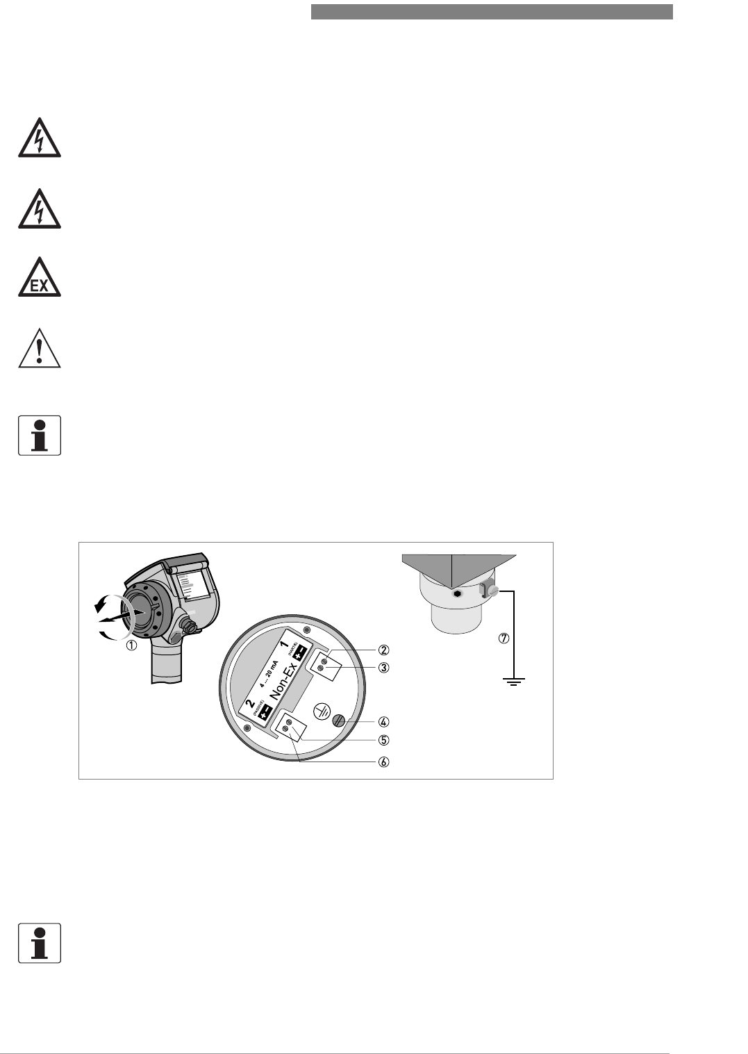
Figure 4-1: Electrical installation
1 Terminal compartment cover
2 Output 1: current output -
3 Output 1: current output +
4 Grounding terminal in the housing
5 Output 2: current output -
6 Output 2: current output +
7 Grounding terminal between the process connection and the converter
INFORMATION!
Output 1 energizes the device and is used for HART
®
communication. If the device has the
second current output option, use a separate power supply to energize output 2.
ELECTRICAL CONNECTIONS 4
31
OPTIWAVE 6300 C
www.krohne.com04/2009 - 4000547001 - HB OPTIWAVE 6300 R01 en
Procedure:
• Remove the housing terminal compartment cover 1.
• Connect the wires to the device. Obey the national electrical codes.
• Make sure that the polarity of the wires is correct.
• Attach the ground to 4 or 7. Both terminals are technically equivalent.
4.2.1 Non-Ex
4.2.2 Ex i
4.2.3 Ex d
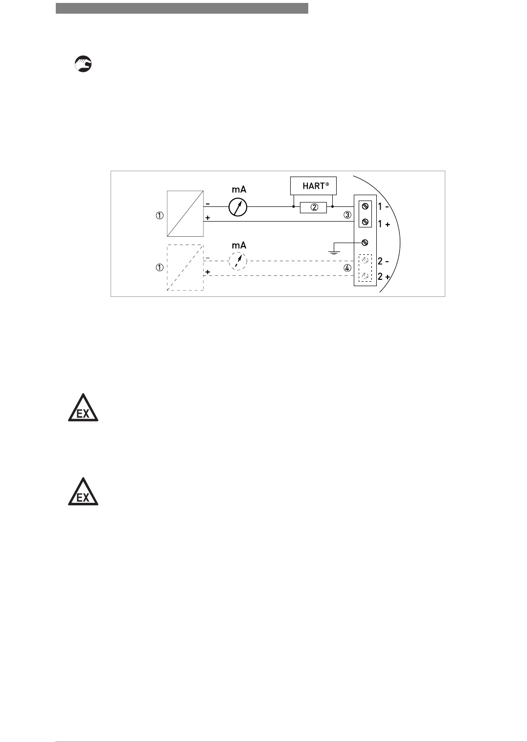
Figure 4-2: Electrical connections for non-Ex devices
1 Power supply
2 Resistor for HART® communication
3 Output 1: 14...30 VDC for an output of 22 mA at the terminal
4 Output 2: 10...30 VDC for an output of 22 mA at the terminal
DANGER!
For electrical data for Ex i applications, refer to the Ex supplements. You can find this
documentation on the CD-ROM delivered with the device or it can be downloaded free of charge
from the website (Downloadcenter).
DANGER!
For electrical data for Ex d applications, refer to the Ex supplements. You can find this
documentation on the CD-ROM delivered with the device or it can be downloaded free of charge
from the website (Downloadcenter).
4 ELECTRICAL CONNECTIONS
32
OPTIWAVE 6300 C
www.krohne.com 04/2009 - 4000547001 - HB OPTIWAVE 6300 R01 en
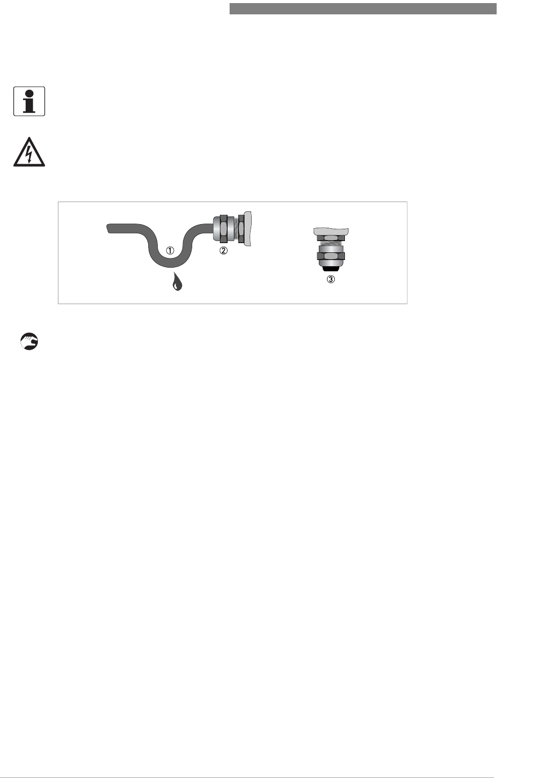
4.3 Protection category
• Make sure that the gaskets are not damaged.
• Make sure that the electrical cables are not damaged.
• Make sure that the electrical cables agree with the national electrical code.
• The cables are in a loop in front of the device 1 so water does not go into the housing.
• Tighten the cable feedthroughs 2.
• Close unused cable feedthroughs with dummy plugs 3.
INFORMATION!
The device fulfills all requirements per protection class IP 66/67 (equivalent to NEMA 6-6X).
DANGER!
Make sure the cable gland is watertight.
Figure 4-3: How to make the installation agree with protection category IP 67
ELECTRICAL CONNECTIONS 4
33
OPTIWAVE 6300 C
www.krohne.com04/2009 - 4000547001 - HB OPTIWAVE 6300 R01 en
4.4 Networks
4.4.1 General information
The device uses the HART® communication protocol. This protocol agrees with the HART®
Communication Foundation standard. The device can be connected point-to-point. It can also
operate in a multi-drop network of up to 15 devices.
Output 1 is factory-set to communicate point-to-point. To change the communication mode from
point-to-point to multi-drop, refer to
Network configuration
on page 59.
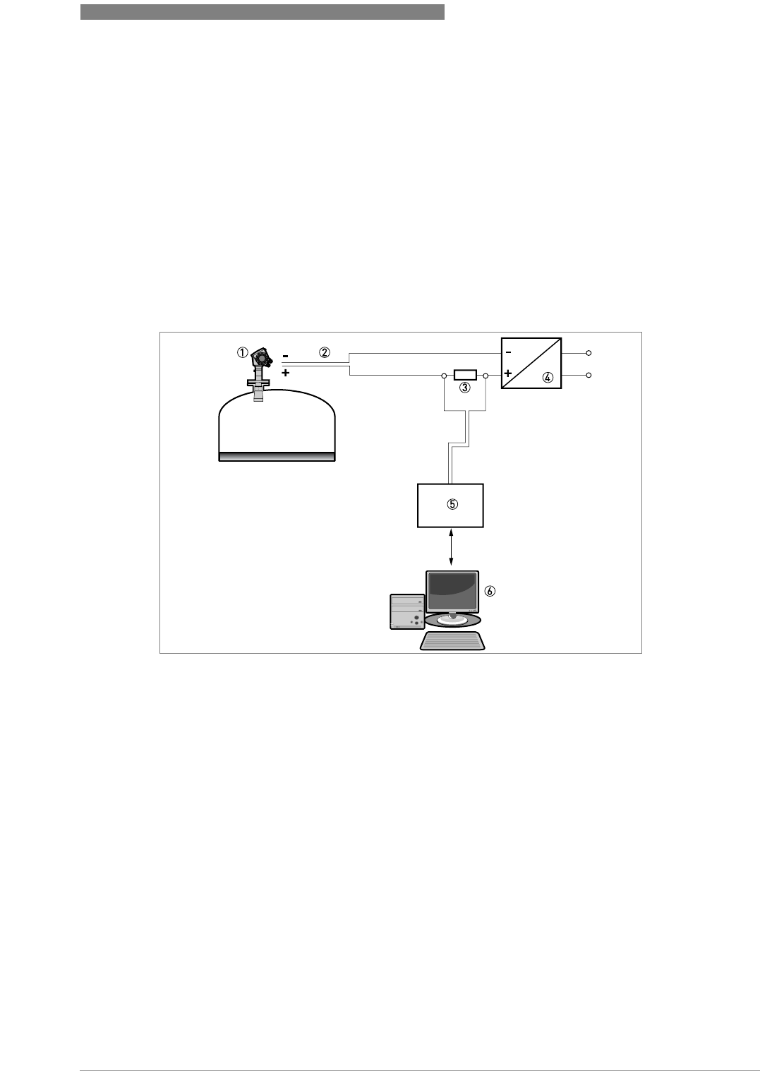
4.4.2 Point-to-point connection
Figure 4-4: Point-to-point connection (non-Ex)
1 Address of the device (0 for point-to-point connection)
2 4...20 mA + HART®
3 Resistor for HART® communication
4 Power supply
5 HART® converter
6 HART® communication software
4 ELECTRICAL CONNECTIONS
34
OPTIWAVE 6300 C
www.krohne.com 04/2009 - 4000547001 - HB OPTIWAVE 6300 R01 en
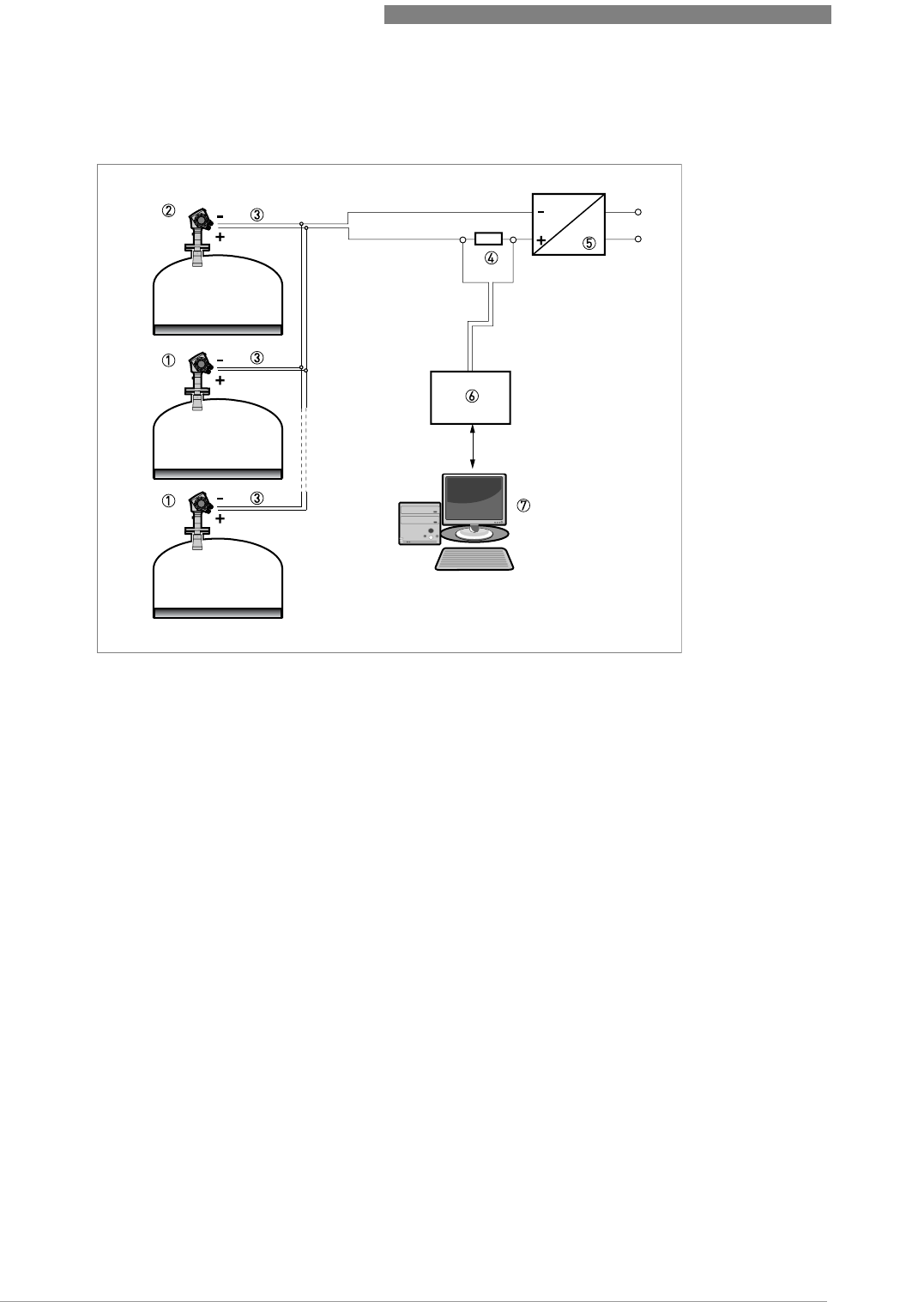
4.4.3 Multi-drop networks
Figure 4-5: Multi-drop network (non-Ex)
1 Address of the device (n+1 for multidrop networks)
2 Address of the device (1 for multidrop networks)
3 4mA + HART
®
4 Resistor for HART® communication
5 Power supply
6 HART® converter
7 HART® communication software

START-UP 5
35
OPTIWAVE 6300 C
www.krohne.com04/2009 - 4000547001 - HB OPTIWAVE 6300 R01 en
5.1 Start-up checklist
Check these points before you energize the device:
•Are all the wetted components (antenna, flange and gaskets) resistant to the product in the
silo?
•Does the information on the signal converter nameplate agree with the operating data?
•Did you correctly install the device on the silo?
•Do the electrical connections agree with the national electrical codes?
5.2 Operating concept
You can read measurements and configure the device with:
•A digital display screen (optional).
•A connection to a system or PC with PACTware™. You can download the Device Type
Manager (DTM) file from the internet site
•A connection to a system or PC with AMS™. You can download the Device Description (DD)
file from the internet site.
•A connection to a HART® Handheld Communicator.
DANGER!
Before you energize the device, make sure that the supply voltage and polarity are correct.
DANGER!
Make sure that the device and the installation agrees with the requirements of the Ex certificate
of compliance.
5 START-UP
36
OPTIWAVE 6300 C
www.krohne.com 04/2009 - 4000547001 - HB OPTIWAVE 6300 R01 en
5.3 Digital display screen
5.3.1 Local display screen layout
5.3.2 Push-button functions
5.3.3 Help screens
When you are in supervisor mode, the local display helps you to configure the device. If you do
not touch any keys after 30 seconds, a help message is displayed. This will explain what the
menu is and what the parameters do. Press > and U (Esc) at the same time to go back to the
menu. If you do not touch the display for another 30 seconds, the message is shown again.
Figure 5-1: Local display screen layout
1 Error icon
2 Tag number or menu name
3 Selected menu item (grey text cannot be selected)
4 U V : scroll up/scroll down
5 Push buttons (refer to the table below)
Push button Description
Left
Return
Down
Up
Esc (Escape)

START-UP 5
37
OPTIWAVE 6300 C
www.krohne.com04/2009 - 4000547001 - HB OPTIWAVE 6300 R01 en
5.3.4 How to start the device
• Connect the converter to the power supply.
• Energize the converter.
iAfter 30 seconds the screen will display "booting up", "starting up" and then the default
screen will appear.
• The device will display readings.
iMeasurements agree with specifications given in the customer order.
5.4 Remote communication with PACTware™
PACTware™ displays measurement information clearly and lets you configure the device from a
remote location. It is an Open Source, open configuration software for all field devices. It uses
Field Device Tool (FDT) technology. FDT is a communication standard for sending information
between the system and the field device. This standard agrees with IEC PAS 62453. Field devices
are easily integrated. Installation is supported by a user-friendly Wizard.
Install these software programs and equipment:
•Microsoft® .NET Framework version 1.1 or later.
•PACTware.
•HART® converter (USB, RS232...).
•The Device Type Manager for the device.
The software and installation instructions are given on the CD-ROM supplied with the device.
You can also download the latest version of PACTware™ and the DTM from our internet site.
Refer also to the PACTware™ consortium site at http://www.pactware.de.
CAUTION!
If the manufacturer received information about the installation, the device will display readings
correctly. If not, refer to the quick setup procedures.
5 START-UP
38
OPTIWAVE 6300 C
www.krohne.com 04/2009 - 4000547001 - HB OPTIWAVE 6300 R01 en
5.5 Remote communication with the AMS™ Device Manager
The AMS™ Device Manager is an industrial Plant Asset Management (PAM) software tool. Its
role is to:
•Store configuration information for each device.
•Support HART® and Fieldbus FOUNDATION™ devices.
•Store and read process data.
•Store and read diagnostic status information.
•Help plan preventive maintenance to reduce a plant's downtime to a minimum.
The DD file is given on the CD-ROM supplied with the device. You can also download it from
our internet site.
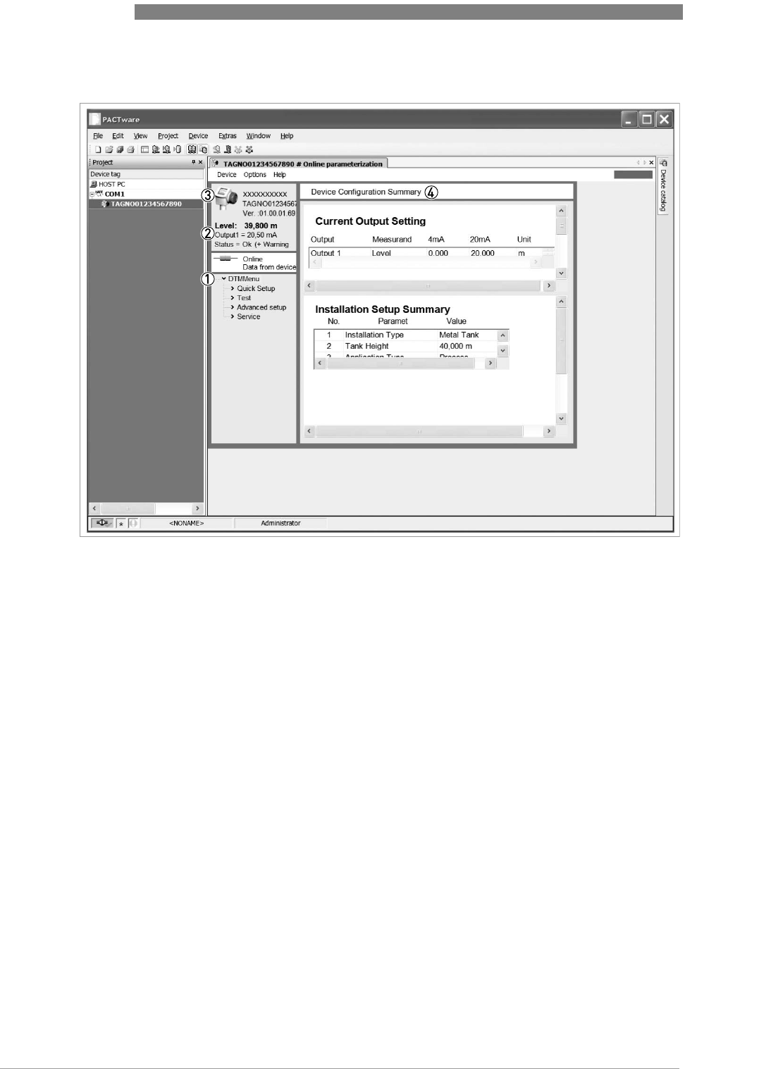
Figure 5-2: Screen from the PACTware™ user interface
1 DTM menu
2 Basic measurement information: level, current output and device status
3 Information for device identification
4 Configuration summary
OPERATION 6
39
OPTIWAVE 6300 C
www.krohne.com04/2009 - 4000547001 - HB OPTIWAVE 6300 R01 en
6.1 User modes
There are 3 modes of operation:
•Operator.
•Supervisor.
•Service.
6.2 Operator mode
The operator can choose what information to display.
This section shows you:
•What each button does in operator mode.
•What special function each button has if it pressed for more than 1 second.
•How to move from one screen of information to another.
Some data will only be available if the device is correctly configured by the supervisor, as
described below.
Push button functions in operator mode
Push button Description Normal function "Hot key" function
Right Change display style 1 Enter program mode 2
Enter - -
Down Scroll down the list of
measurement parameters 3
The screen shown at this time
becomes the default screen 2
Up Scroll up the list of
measurement parameters 3
Display language will change to
English 4
Esc (Escape) - -
1value, value and picture, or value and bar graph
2when you press this button for 1 second
3level, distance, volume etc.
4when you press this button for 3 seconds. Press the button again and it will go back to the original language.

6 OPERATION
40
OPTIWAVE 6300 C
www.krohne.com 04/2009 - 4000547001 - HB OPTIWAVE 6300 R01 en
Screens in operator mode
Text and image
screen
Go to % current output
screen
Go to Text screen Go to
U U U
Level > Level > Level > (Text
and image)
U V U V U V
Distance >Distance >Distance > (Text
and image)
U V U V U V
Volume 1 >Volume 1 >Volume 1 > (Text
and image)
U V U V U V
Mass 2 >Mass 2 >Mass 2 > (Text
and image)
U V U V U V
Ullage volume 1 >Ullage volume 1 >Ullage volume 1 > (Text
and image)
V V U V
Back to the
top of the list Back to the
top of the list Reflectivity 1
U V
Signal screen 3
V
Back to the top
of the list
1only available if you created a volume table. Refer to the conversion quick setup menu in supervisor mode.
2only available if you created a mass table. Refer to the conversion quick setup menu in supervisor mode.
3shows a graph of discrete radar reflection signals against distance. This is used to view reflections measured by the
device. Press > to move the cursor from one signal peak to another.

OPERATION 6
41
OPTIWAVE 6300 C
www.krohne.com04/2009 - 4000547001 - HB OPTIWAVE 6300 R01 en
6.3 Supervisor mode
6.3.1 General notes
Configure your device in supervisor mode. You can:
•Use the quick setup menus to configure your device quickly. For more data about quick setup
menus, refer to
Function description
on page 46 (Table A. Quick setup).
•Use the advanced setup menu to find single items for device configuration. For more data
about menu items, refer to
Function description
on page 46 (Table C. Advanced setup).
•Save quicklinks for items that you use regularly. For more data about quicklinks (menu items
A.2 to A.6), refer to
Function description
on page 46 (Table A. Quick setup).
•Error finding and troubleshooting procedures are described in the test menu. For more data,
refer to
Function description
on page 46 (Table B. Test).
6.3.2 How to get access to the supervisor mode
Do the steps that follow:
• Press the push button > for one second.
iThis displays the login screen.
• Press the push buttons U or V to select supervisor from the list.
• Press the push button ^.
iThe screen displays where to type in the password.
• Type in the password. The factory-set password is > ^ V U > ^.
iThe device displays the message "Login successful" and then the main menu for supervisor
mode.
You can change the password for the supervisor mode (menu item C.5.2.2). For more data, refer
to
Function description
on page 46 (Table C. Advanced setup).
The main menu shows:
•Quick Setup menu.
•Test menu.
•Advanced Setup menu.
You cannot select "Service menu" in supervisor mode. Menus that can be selected are in black
text. Menus that cannot be selected are in grey text.
If you go back to operator mode, you will have access to the supervisor mode, without password
security, for 30 minutes.

6 OPERATION
42
OPTIWAVE 6300 C
www.krohne.com 04/2009 - 4000547001 - HB OPTIWAVE 6300 R01 en
6.3.3 Menu overview
A quick setup
A.1 setup mode
A.2 quick link 1 (default: error records)
A.3 quick link 2 (default: contrast)
A.4 quick link 3 (default: language)
A.5 quick link 4 (default: length unit)
A.6 quick link 5 (default: display)
B test
B.1 test
B.2 information
C advanced setup
C.1 installation setup
C.2 I/O 1
C.3 output 1 (HART)
C.4 output 2 (passive) 2
C.5 device setup
C.6 reset
1input/output options. This menu is not available at this time.
2optional
OPERATION 6
43
OPTIWAVE 6300 C
www.krohne.com04/2009 - 4000547001 - HB OPTIWAVE 6300 R01 en
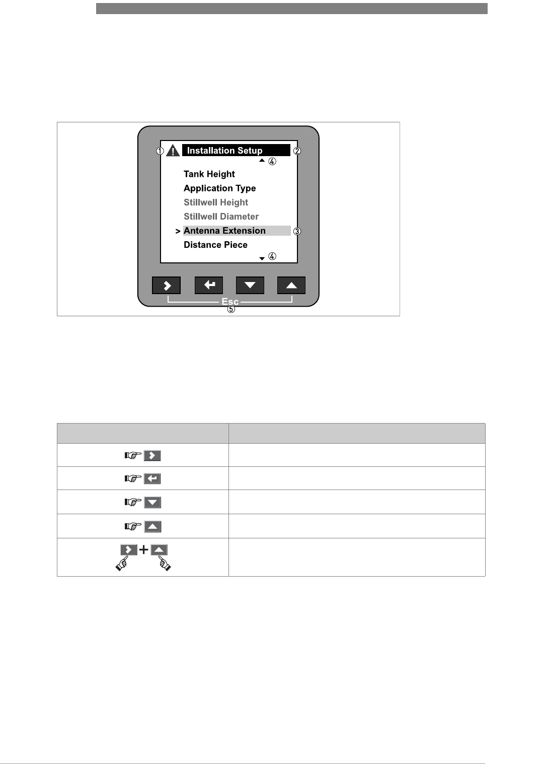
6.3.4 Push-button functions
This is what you see when you are in the list of menus in supervisor mode. The functions of the
push-buttons are given in the table that follows:
Functions of push-buttons in the menu lists
Menu navigation
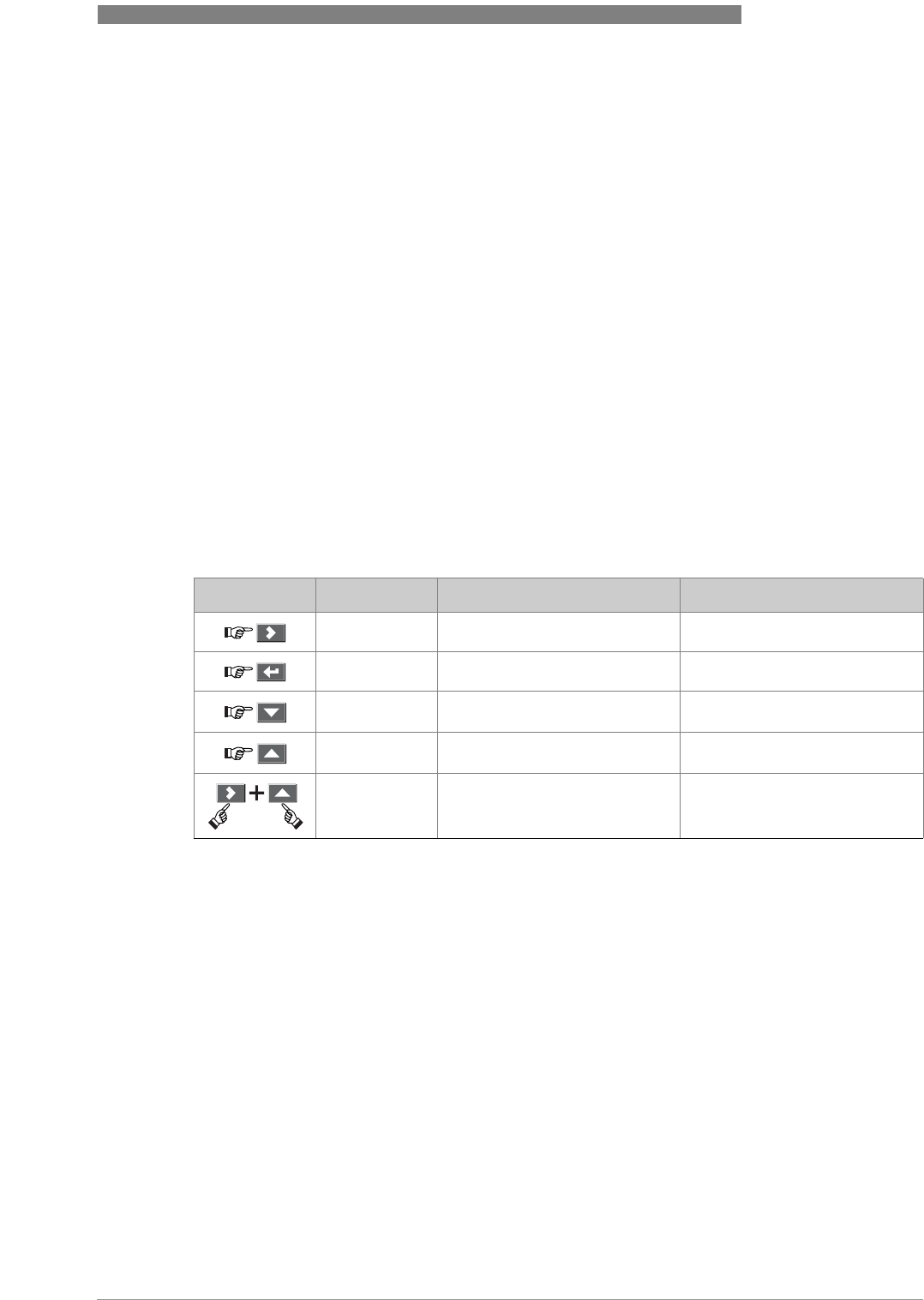
Figure 6-1: Menu navigation
1 Menu selection bar
2 Header bar
3 Menu list
4 Menu item that is not available (in grey text)
Push button Description Function
Right Go to the next menu level
Enter -
Down Move the menu selection bar down the list
Up Move the menu selection bar up the list
Esc (Escape) Go back to the menu level you were on before
6 OPERATION
44
OPTIWAVE 6300 C
www.krohne.com 04/2009 - 4000547001 - HB OPTIWAVE 6300 R01 en
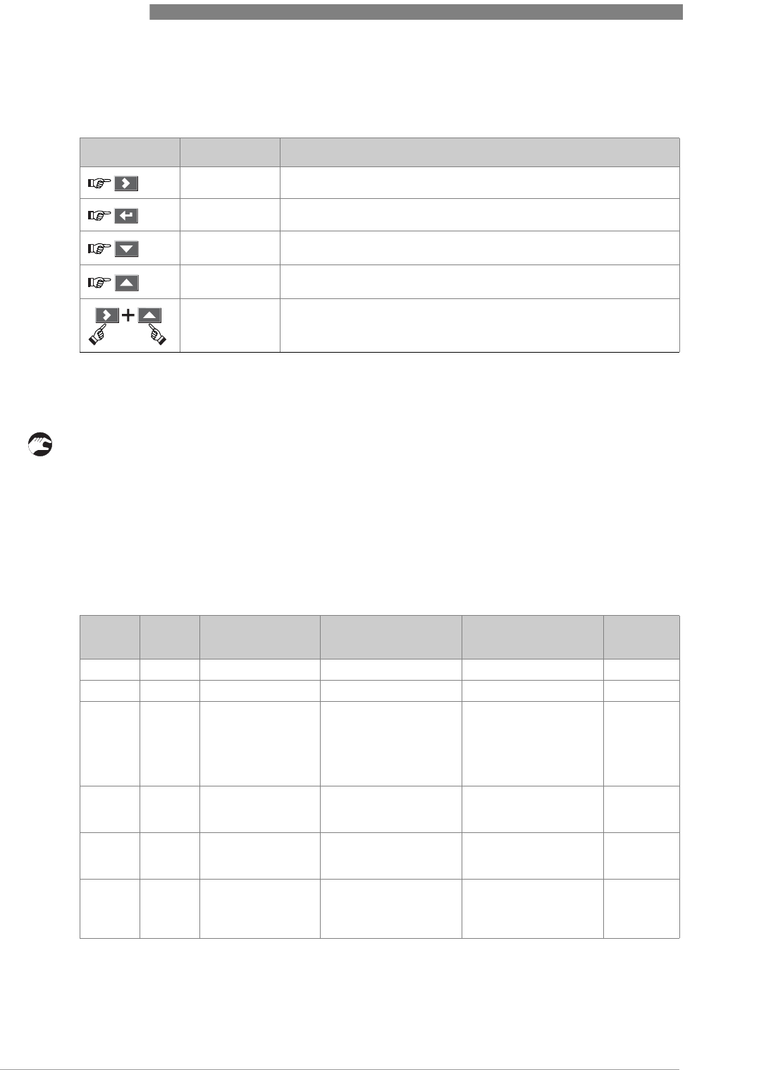
This is what you see when you choose a menu item that has a list of parameters. The functions of
the push-buttons are given in the table that follows:
Function of push-buttons in menu items that have a list of parameters
Lists of parameters in menu items
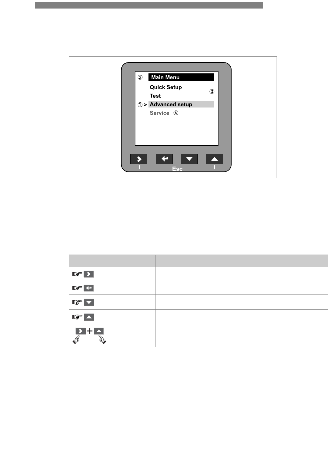
Figure 6-2: Lists of parameters in menu items
1 Parameter selection bar
2 Menu name
3 Parameter used at this time
Push button Description Function
Right -
Enter Select the parameter and go back to the menu
Down Move the menu selection bar down the list
Up Move the menu selection bar up the list
Esc (Escape) Go back to the menu 1
1this does not confirm that you selected a new parameter
OPERATION 6
45
OPTIWAVE 6300 C
www.krohne.com04/2009 - 4000547001 - HB OPTIWAVE 6300 R01 en
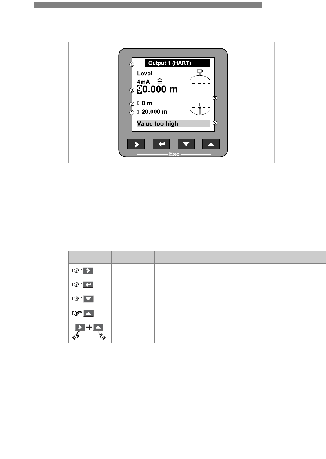
This is what you see when you choose a menu item that has a value. The functions of the push-
buttons are given in the table that follows:
Function of push-buttons in menu items that have values
Values in menu items
Figure 6-3: Values in menu items
1 Maximum value
2 Minimum value
3 Cursor on the digit to be changed
4 Menu name
5 Illustration of menu item
6 Error message
Push button Description Function
Right Move the cursor to the next digit on the right
Enter Select the parameter and go back to the menu
Down Decrease the digit value
Up Increase the digit value
Esc (Escape) Go back to the menu 1
1this does not confirm that you selected a new parameter
6 OPERATION
46
OPTIWAVE 6300 C
www.krohne.com 04/2009 - 4000547001 - HB OPTIWAVE 6300 R01 en
If you press the push-buttons for 1 second, you can use these hotkey functions:
Hotkey functions in supervisor mode
How to save settings
• When you have changed parameters in all the necessary menu items, press ^ to accept the
new parameter.
• Press > and U at the same time to go back to the Save settings screen.
• The device will ask you to save or cancel your settings. Select Save to accept the new settings
or Cancel to reject them.
iThe display goes back to operator mode.
6.3.5 Function description
A. Quick setup
Push button Description Function
Right Create a quick link 1
Enter -
Down -
Up Screen displays information in English 2
Esc (Escape) Go back to the operator mode
1select a menu item from the Advanced Setup menu list
2press this push-button for 3 seconds
Menu
No.
Step Function Function description Selection list Default
A.0 quick setup
A.1 setup mode
A.1.1 complete This follows the steps
given in the
application,
installation,
conversion and output
setup modes.
A.1.2 installation Follow this procedure
to describe the silo and
the product.
1installation type The silo material. metal / concrete silo;
plastic silo; free air
application
metal silo
2tank height The distance from the
silo connecting flange
face/thread stop to the
silo bottom.
min-max: 0.20…80 m /
0.54…262 ft 20 m

OPERATION 6
47
OPTIWAVE 6300 C
www.krohne.com04/2009 - 4000547001 - HB OPTIWAVE 6300 R01 en
3application type The conditions in
which the device is
used. If the surface of
the product is flat,
select "flat surface". If
there is a slightly
uneven surface, select
"slant surface". If the
surface has a steep
slope, select "big
slope".
slant surface; flat
surface; big slope slant
surface
4blocking distance A zone given by the
user where it is not
possible to measure.
We recommend at
least 100 mm / 4¨
below the antenna.
antenna extension
(C.1.6)…tank height
(C.1.2) 1
1
5settings summary
6save / cancel save, cancel 2
A.1.3 empty spectrum Fixed and moving
objects in the tank
cause interference
signals. Put them
through this filter to
correctly measure the
silo contents.
1do you have a
completely filled
tank?
If the silo is full, it is
not possible to
complete this
procedure. The silo
must be partially filled
or empty.
yes; no yes
2are all moving
parts in the tank in
motion?
We recommend that
you switch on moving
equipment to filter all
interference signals.
yes; no yes
3is your tank
partially filled or
empty?
If the silo is partially
filled, the device must
include the silo
contents when it filters
the signal.
partially filled; empty partially
filled
4distance If the silo is partially
filled, type in a
distance shorter than
that between the
flange and the tank
contents.
min-max: 0…tank
height 10 m /
32.808 ft
5do you want to
consider average
or maximum value
for recording?
Use the average value
for silos which contain
fixed objects only. Use
the maximum value for
silos which contain
many objects or
moving objects.
average; maximum 0.1 m /
0.33 ft
6empty spectrum
recording is in
progress
………
7empty spectrum
graph ………
Menu
No.
Step Function Function description Selection list Default

6 OPERATION
48
OPTIWAVE 6300 C
www.krohne.com 04/2009 - 4000547001 - HB OPTIWAVE 6300 R01 en
8do you want to save
the spectrum? If you save this data,
the device will use it
when it measures the
silo contents.
save, cancel 2 save
A.1.4 conversion Follow this procedure
to set the device up to
display readings in
volume, mass or user-
defined units.
sub-
menu conversion
submenu [volume]
1free unit yes, no no
2table length unit m, cm, mm, inch, ft,
free unit m
3conversion wizard volume
4tank shape This sub-procedure
uses the information
given here to find the
volume. You have to
type in the silo shape,
height, width and
length.
... ...
5conversion unit The displayed unit in
operator mode. m³, L, US gal, GB gal,
ft³, bbl m³
6conversion table A table that converts
product level to
product volume.
sub-
menu conversion
submenu [mass] -
1free unit yes, no no
2table length unit m, cm, mm, inch, ft,
free unit m
3conversion wizard mass
4type in product
density? yes, no yes
5product density min-max:
0…20000 kg/m3 0
6tank shape This sub-procedure
uses the information
given here to find the
volume. You have to
type in the silo shape,
height, width and
length.
... ...
7conversion unit The conversion unit is
given as a volume if the
product density is
given. If not, choose a
mass unit.
m³, L, US gal, GB gal,
ft³, bbl or Tons, kg, US
Tons, GB Tons
m³ or Tons
8conversion table A table that converts
product level to
product mass.
sub-
menu conversion
submenu [free
unit]
If you cannot find the
units or silo shape in
the menu, you can
customize the
conversion table.
-
Menu
No.
Step Function Function description Selection list Default

OPERATION 6
49
OPTIWAVE 6300 C
www.krohne.com04/2009 - 4000547001 - HB OPTIWAVE 6300 R01 en
1free unit yes, no no
2customer length
unit A non-standard length
unit for the conversion
table. This is defined
by the supervisor.
LEN_FREE
_
3customer length
ratio The conversion factor
between the length
unit selected in C.5.1.4
(length unit) and
C.5.1.7 (customer
length unit). This ratio
is a multiple of 1 mm.
min-max: 1…99999 1
4customer
conversion unit A non-standard
conversion unit for the
conversion table. This
is defined by the
supervisor.
CO_FR_UN
5No. Of LVM Entries The number of lines in
the conversion table. min-max: 0…50 2
6conversion table A table that converts
product level to
another physical
parameter.
... save / cancel save, cancel 2 save
A.1.5 outputs Follow this procedure
to describe the output
characteristics.
-
1output 1: function Select an output
function to scale the
current values. This is
not displayed in the
operator mode.
level, distance, volume
(mass), ullage volume,
reflection
level
2output 1: 4 mA
setting This assigns a
measurement value to
4mA.
min.-max: 0…20 m /
0…65.62 ft 0m/ 0ft
3output 1: 20 mA
setting This assigns a
measurement value to
20 mA.
min.-max: 0…90 m /
0…295.29 ft depends
on the
output
function
5output 1: output
range This sets the effective
range of output 1 with
or without over-run.
3.8…20.5 mA
(NAMUR), 4…20 mA 4…20 mA
6output 1: error
handling This sets the behaviour
of current output 1 if
an error occurs.
3.6 mA, 22 mA, Hold
(4...20 mA range only) 22 mA
7output 1: HART®
address Any HART® address
greater than 0 will
activate HART®
multidrop mode.
Current output stays
constant at 4 mA.
min.-max: 0…15 0
8output 2: function
3Select an output
function to scale the
current values. This is
not displayed in the
operator mode.
level, distance, volume
(mass), ullage volume,
reflection
level
9output 2: 4 mA
setting 3
This assigns a
measurement value to
4mA.
min.-max: 0…20 m /
0…65.62 ft 0m/ 0ft
Menu
No.
Step Function Function description Selection list Default

6 OPERATION
50
OPTIWAVE 6300 C
www.krohne.com 04/2009 - 4000547001 - HB OPTIWAVE 6300 R01 en
B. Test
10 output 2: 20 mA
setting 3
This assigns a
measurement value to
20 mA.
min.-max: 0…90 m /
0…295.29 ft depends
on the
output
function
11 output 2: output
range 3
This sets the effective
range of output 2 with
or without over-run.
3.8…20.5 mA
(NAMUR), 4…20 mA 4…20 mA
12 output 2: error
handling 3
This sets the behaviour
of current output 2 if
an error occurs.
3.6 mA, 22 mA, Hold
(4...20 mA range only) 22 mA
13 settings summary read only
save / cancel save, cancel 2 save
A.2 quick link 1 Direct link to an item in
the advanced setup
menu
go to a function in the
advanced setup menu
and press > for 1
second. You can store
up to 5 functions in this
way.
error
records
A.3 quick link 2 Direct link to an item in
the advanced setup
menu
go to a function in the
advanced setup menu
and press > for 1
second. You can store
up to 5 functions in this
way.
measurem
ent quality
A.4 quick link 3 Direct link to an item in
the advanced setup
menu
go to a function in the
advanced setup menu
and press > for 1
second. You can store
up to 5 functions in this
way.
language
A.5 quick link 4 Direct link to an item in
the advanced setup
menu
go to a function in the
advanced setup menu
and press > for 1
second. You can store
up to 5 functions in this
way.
length unit
A.6 quick link 5 Direct link to an item in
the advanced setup
menu
go to a function in the
advanced setup menu
and press > for 1
second. You can store
up to 5 functions in this
way.
display
mode
1depends on other user functions
2step ignored if complete setup selected
3optional
Menu
No.
Function Function description Selection list Default
B.0 test
B.1 test This checks the device outputs and
performs common device tests.
B.1.1 show output 1 This displays analogue output 1 value
[mA]. read only
Menu
No.
Step Function Function description Selection list Default

OPERATION 6
51
OPTIWAVE 6300 C
www.krohne.com04/2009 - 4000547001 - HB OPTIWAVE 6300 R01 en
B.1.2 set output 1 This sets analogue output 1 to a test
value [mA] selected from a list.
Output will change to the selected
value, independent of the measured
value.
3.6, 4, 6, 8, 10, 12, 14,
16, 18, 20 or 22 mA 4mA
B.1.3 show output 2 This displays analogue output 2 value
[mA]. read only
B.1.4 set output 2 This sets analogue output 2 to a test
value [mA] selected from a list.
Output will change to the selected
value, independent of the measured
value.
3.6, 4, 6, 8, 10, 12, 14,
16, 18, 20 or 22 mA 4mA
B.1.5 internal test This initiates the hardware test. The
device displays the results. read only
B.2 information A summary of information relating to
the device
B.2.1 outputs Analogue output settings. This
includes assigned functions, 4 … 20
mA scale settings, error handling and
HART® parameters.
read only
B.2.2 15 minute log A log of output values for the last 15
minutes. A log is taken every 10
seconds and displayed on a graph.
read only
B.2.3 device
identification This displays device order no, V-no,
service no, firmware 1 version,
firmware 2 version, firmware 3
version and Ex approval details.
read only
B.2.4 quick setup
summary A summary of the parameters
entered in the quick setup menu read only
B.2.5 TAG number The TAG number can be seen and
updated here ?TAGNO012
34567890
temperature Temperature of the electronics block.
The display will automatically switch
off if the temperature is below -20°C /
-4°F or above +60°C / +140°F
read only
B.2.6 error records A log of device errors. Scroll down
the list and press ^ to display the
error details. Opening a log will
remove the error icon if it appeared
in operator mode.
read only
measurement
quality Status of device errors at this time. A
"tick" symbol next to an error in the
list shows that this error is active and
may have an unwanted effect on the
device.
read only
B.2.7 customer
length unit Non-standard length unit for the
conversion table. This is defined by
the supervisor. Go to supervisor >
advanced setup > device setup >
display settings > customer length
unit or follow the conversion quick
setup procedure.
read only
B.2.9 customer
conversion unit Non-standard conversion unit for the
conversion table. This is defined by
the supervisor. Go to supervisor >
advanced setup > device setup >
display settings > customer
conversion unit or follow the
conversion quick setup procedure.
read only
Menu
No.
Function Function description Selection list Default

6 OPERATION
52
OPTIWAVE 6300 C
www.krohne.com 04/2009 - 4000547001 - HB OPTIWAVE 6300 R01 en
C. Advanced setup
Menu
No.
Function Function description Selection list Default
C.0 advanced setup Select single menu items to
fine-tune the device.
C.1 installation
setup
C.1.1 installation
type The installation on the silo for
the device. metal / concrete silo, plastic
silo, free air application metal /
concrete
silo
C.1.2 tank height The distance from the silo
connecting flange face/thread
stop down to the bottom of
the silo.
min-max:
0.20…80 m / 0.54…262 ft 20 m /
65.61 ft
C.1.3 application type The conditions in which the
device is used. If the surface
of the product is flat, select
"flat surface". If there is a
slightly uneven surface,
select "slant surface". If the
surface has a steep slope,
select "big slope".
flat surface, slant surface, big
slope slant
surface
C.1.4 stillwell height Not available. For liquid
applications only. n/a n/a
C.1.5 stillwell
diameter Not available. For liquid
applications only. n/a n/a
C.1.6 antenna
extension Optional antenna extension
for the device. These are
attached between the flange
and the antenna. Each part is
105 mm / 4.1¨ long.
min-max: 0…5000.00 mm /
0…196.85¨0mm / 0¨
C.1.7 distance piece Optional distance piece
between the converter and
the process connection.
min-max: 0…5000.00 mm /
0…196.85¨0mm/ 0¨
C.1.8 overfill
detection If this function is switched on,
the device will monitor the
level even if it is in the
blocking distance. The
displayed output stays fixed at
the blocking distance, but an
error message will warn the
user that the silo is
overfilling.
yes, no no
C.1.9 blocking
distance The distance from the flange
to the top limit of the
measuring range. If the
distance is less than the
blocking distance, the device
continues to display the
blocking distance.
min-max:
0.220 m…tank height /
0.72 ft…tank height
0.3m/ 1ft
C.1.10 reference
offset Offset relating to a reference
location (distance). This value
is positive when the reference
location is above the device
flange face and negative if
below.
min-max:
-tank height…50 m /
-tank height...164.05 ft
0m/ 0ft

OPERATION 6
53
OPTIWAVE 6300 C
www.krohne.com04/2009 - 4000547001 - HB OPTIWAVE 6300 R01 en
C.1.11 tank bottom
offset Offset relating to a reference
location (level). The device
reference point for this
parameter is the bottom of
the silo (set in menu item
C.1.2.0). This value is positive
when the reference location
is below the silo bottom and
negative if above.
min-max:
-tank height...3000 m /
-tank height...9843 ft
0m/ 0ft
C.1.12 time constant Using this function, the device
processes several
measurement readings to
filter out disturbances.
Increasing the time constant
will smoothen the integrated
readings, decreasing will
roughen the readings.
min-max: 1...100 seconds 3 seconds
C.1.13 measuring
mode The device uses the dielectric
constant of the tank contents
to monitor level. If εr is low,
select "TBF partial" mode. If
Er is very low (1.5), select
"TBF full". If you want the
device to measure level using
the first radar signal it finds,
select "option 1". If you want
the device to measure level
but ignore all the radar
signals stored in the empty
spectrum scan, select "option
2". "option 3" is not yet
available. For other uses,
select "direct measuring".
direct measuring; TBF
partial, TBF full, option 1,
option 2, option 3
direct
measuring
C.1.14 product Er The device automatically
calculates the level based on
the product εr. If you select
"TBF partial" or "TBF full" in
item C.1.13, you can change
this value manually to adjust
readings.
min-max: 1.01…99.90 4
C.1.15 tracing velocity This function sets the
maximum rate of change of
level. The measured value
cannot change faster than the
tracing velocity.
min-max:
0.001…10.000 m/min /
0.003…32.8 ft/min
0.5 m/min /
1.64 ft/min
C.1.16 multiple
reflections Multiple reflections will cause
the device to display smaller
readings. Objects in the tank,
sharp corners, installation of
the device on a large nozzle
or at the centre of a dome
roof can cause multiple
reflections. A very calm
surface or a tank with a small
convex or flat roof can also
cause multiple reflections.
yes; no no
Menu
No.
Function Function description Selection list Default

6 OPERATION
54
OPTIWAVE 6300 C
www.krohne.com 04/2009 - 4000547001 - HB OPTIWAVE 6300 R01 en
C.1.17 empty
spectrum
on/off
This function starts and stops
interference signal filter.
Interference signals are the
result of fixed and moving
obstacles inside the silo. If
you must use do a spectrum
analysis, record an empty
spectrum first. This is done in
the Quick setup menu under
empty spectrum (A.1.3.0).
on; off off
C.1.19 units for tables Sub-menu for volume and
mass conversion operations.
C.1.19.1 table length
unit The length unit used in the
conversion table. If "free unit"
is selected, the device uses
the unit name in menu item
C.5.1.7.
m, cm, mm, inch, ft, free unit m
C.1.19.2 conversion unit The volume or mass unit used
in the conversion table. If
"free unit" is selected, the
device uses the unit name in
menu item C.5.1.9.
m3, L, US gal, GB gal, ft3, bbl,
Tons, Kg, US Tons, GB Tons,
free unit
m3
C.1.20 product density A value greater than 0 that is
used with a volume
conversion table to start the
mass calculation. This menu
item is not available if you
have selected a mass unit.
0…20000 kg/m3 0
C.1.21 volume/mass
table The device uses this table to
display volume and mass
readings. Give the number of
entries on the table. Press ^.
Type in the level and
corresponding volume/ mass
values.
Number of entries min.-max:
0…50 0. Table
units are
selected in
menu items
C.1.19.1
and
C.1.19.2.
C.1.22 linearisation
table The device uses this table to
increase on-site accuracy.
Give the number of entries
plotted. Fill the silo. Make a
reference measurement and
type in the correct value next
to the device reading.
Number of entries min.-max:
0…50 0
C.2 I/O For fieldbus. Not yet
available.
C.3 output 1
(HART)
C.3.1 output function Select an output function to
scale the current values. This
is not displayed in the
operator mode.
level, distance, volume/mass,
ullage volume, reflection level
C.3.2 4mA setting Give a measurement value to
4mA. min.-max: depends on other
functions. Refer to the
dependency tables below.
0m/ 0ft
C.3.3 20 mA setting Give a measurement value to
20 mA. min.-max: depends on other
functions. Refer to the
dependency tables below.
depends on
the output
function
C.3.4 output range Sets the effective range of
output 1 either with or
without over-run.
min.-max: 3.8…20.5 mA
(NAMUR), 4…20 mA 4…20 mA
C.3.5 error handling Sets the behaviour of current
output 1 if an error occurs. 3.6 mA, 22 mA, Hold 22 mA
Menu
No.
Function Function description Selection list Default

OPERATION 6
55
OPTIWAVE 6300 C
www.krohne.com04/2009 - 4000547001 - HB OPTIWAVE 6300 R01 en
error handling
delay The time after which the
device shows there is a
measurement error.
min.-max: 0…900 seconds 10 seconds
C.3.6 HART address Any HART® address greater
than 0 will activate HART®
multidrop mode. The current
output stays constant at
4mA.
min.-max: 0…15 0
C.4 output 2
(passive)
C.4.1 output function Select an output function to
scale the current values. This
is not displayed in the
operator mode.
level, distance, volume/mass,
ullage volume, reflection level
C.4.2 4mA setting Give a measurement value to
4mA. min.-max: depends on other
functions. Refer to the
dependency tables below.
0m/ 0ft
C.4.3 20 mA setting Give a measurement value to
20 mA. min.-max: depends on other
functions. Refer to the
dependency tables below.
depends on
the output
function
C.4.4 output range Sets the effective range of
output 2 either with or
without over-run.
min.-max: 3.8…20.5 mA
(NAMUR), 4…20 mA 4…20 mA
C.4.5 error handling Sets the behaviour of current
output 2 if an error occurs. 3.6 mA, 22 mA, Hold 22 mA
error handling
delay The time after which the
device shows there is a
measurement error. This
value is set in the output 1
menu.
read only 10 seconds
C.5 device setup This menu covers all items
directly related to the display
of information and access to
the supervisor menu.
C.5.1 display settings To display the information you
need, refer to these menu
items.
C.5.1.1 language English, French, German,
Italian, Japanese, Mandarin,
Portuguese, Russian, Spanish
Factory set
C.5.1.2 display mode The display screen status will
change after the time given in
C.5.1.3. (time delay). None
switches off this functionality,
Auto-off switches off the
display automatically and
Default screen will show the
selected default screen. To
reset to the default screen,
press V for 1 second in the
operator mode.
disable, auto-off, default
screen. disable
C.5.1.3 time delay The time after which the
display will switch to the
status set in C.5.1.2 (display
mode).
1, 3, 5, 10 minutes 1 minute
Menu
No.
Function Function description Selection list Default

6 OPERATION
56
OPTIWAVE 6300 C
www.krohne.com 04/2009 - 4000547001 - HB OPTIWAVE 6300 R01 en
Data dependencies for the 4 mA settings of outputs 1 and 2
contrast menu The contrast control for the
display screen. You can select
a shade of grey between light
grey (level 1) and black (level
9).
min.-max: level 1…9level 5
C.5.1.4 length unit The length unit displayed in
operator mode. m, cm, mm, inch, ft,
ft+inch+1/18inch,
ft+inch+1/32inch, free unit
m
C.5.1.5 volume unit The volume unit displayed in
operator mode. m³, L, US gal, GB gal, ft³, bbl m³
C.5.1.6 mass unit The mass unit displayed in
operator mode. Tons, kg, US tons, GB tons kg
C.5.1.7 customer
length unit A non-standard length unit
for the conversion table. This
is defined by the supervisor.
LEN_FREE
_
C.5.1.8 customer
length ratio The conversion factor
between the length unit
selected in C.5.1.4 (length
unit) and C.5.1.7 (customer
length unit). This ratio is a
multiple of 1 mm.
min.-max: 1…99999 1
C.5.1.9 customer
conversion unit non-standard conversion unit
for the conversion table. This
is defined by the supervisor.
CO_FR_UN
C.5.2 Passwords To change user passwords,
refer to these menu items.
C5.2.2 supervisor This changes the supervisor
password. Press the push
buttons up to six times in any
order. This will be the new
password. To confirm the
change, enter the new
password a second time.
>^VU>^
C.6 reset To reset the device to default
settings, refer to these menu
items.
C.6.2 clear error
record Erase the error record in
menu item B.2.6. Press ^ to
confirm.
C.6.3 restart If the device is not functioning
properly, this menu item will
restart the device. Press ^ to
confirm.
Output function Minimum value Maximum value Default
Level 0m <20 mA setting for level 0m
Volume 0.00 m³<20 mA setting for volume 0m³
Mass 0.00 kg <20 mA setting for mass 0kg
Distance 0m <20 mA setting for distance 0m
Ullage volume 0.00 m³<20 mA setting for ullage volume 0m³
Ullage mass 0.00 kg <20 mA setting for ullage mass 0kg
Menu
No.
Function Function description Selection list Default
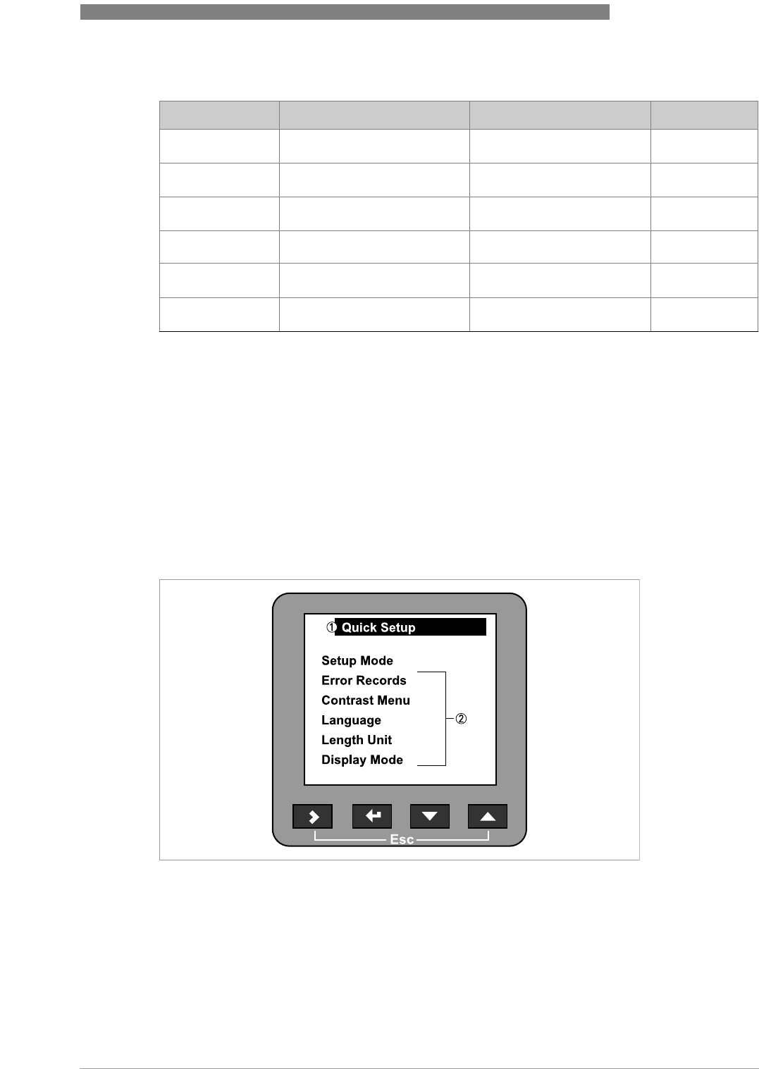
OPERATION 6
57
OPTIWAVE 6300 C
www.krohne.com04/2009 - 4000547001 - HB OPTIWAVE 6300 R01 en
Data dependencies for the 20 mA settings of outputs 1 and 2
6.4 Further information on device configuration
6.4.1 Quick Links
If you frequently use a menu item, you can create a Quick Link. This lets you quickly find and
configure items in the advanced setup menu. Five Quick Link memory spaces are available in the
Quick setup submenu. Go to Supervisor Menu > Quick Setup.
Output function Minimum value Maximum value Default
Level >4 mA setting for level Tank height + TBO + RO 1 Tank height +
TBO - BD 2
Volume >4 mA setting for volume Max value in the volume table Max value in the
volume table
Mass >4 mA setting for mass Max value in the mass table Max value in the
mass table
Distance >4 mA setting for distance Tank height + TBO + RO 3 Tank height + RO
4
Ullage volume >4 mA setting for ullage volume Max value in the volume table Max value in the
volume table
Ullage mass >4 mA setting for ullage mass Max value in the mass table Max value in the
mass table
1TBO = Tank Bottom Offset (C.1.9). RO = Reference Offset (C1.10).
2TBO = Tank Bottom Offset (C.1.9). BD = Blocking Distance (C.1.11).
3TBO = Tank Bottom Offset (C.1.9). RO = Reference Offset (C1.10). BD = Blocking Distance (C.1.11).
4RO = Reference Offset (C1.10).
Figure 6-4: The list of quick links
1 Menu name
2 Quick links

6 OPERATION
58
OPTIWAVE 6300 C
www.krohne.com 04/2009 - 4000547001 - HB OPTIWAVE 6300 R01 en
How to create a Quick Link
• Go to Supervisor Menu > Advanced Setup.
• Select a menu item with the U and V push buttons.
• Press the > push button for one second.
iThe device saves this menu item as a Quick Link. Example text: Mass Unit has been
assigned to Quick Link 2
How to open a Quick Link
• Go to Supervisor Menu > Quick Setup.
• Select a Quick Link with the U and V push buttons.
• Press the > push button.
iThis opens the menu item. You can configure the device.
6.4.2 Protection of the device settings
The Passwords menu lets you change the supervisor password.
How to change the supervisor password
• Go to Supervisor > Advanced setup > Device setup > Passwords > Supervisor.
• Type in the new 6-character password (Press the 4 buttons in any sequence).
• Type in the new 6-character password again.
iIf the second entry is not the same as the first, the device will display the error message
"Password mismatch". Press > + U at the same time and type in the new 6-character
password again.
• Press > and U (Esc) at the same time to go back to the "save settings" window.
• Select Save and press ^.
iThe device will go back to operator mode.
INFORMATION!
The Quick Links are saved to one of the five memory spaces. They are saved in sequence. The
first Quick Link is saved to Quick Link 1, the second to Quick Link 2 and so on. If you have already
saved five Quick Links, the next Quick Link will be saved to Quick Link 1.
INFORMATION!
Make a note of the password and keep it in a safe place. If you lose the password, please contact
your supplier.
OPERATION 6
59
OPTIWAVE 6300 C
www.krohne.com04/2009 - 4000547001 - HB OPTIWAVE 6300 R01 en
6.4.3 Network configuration
The device uses HART® communication to send information to HART®-compatible equipment. It
can operate in either point-to-point or multidrop mode. The device will communicate in
multidrop mode if you change the HART® address of output 1.
How to change from point-to-point to multidrop mode
• Enter supervisor mode.
• Go to Advanced Setup > Output 1 (HART) > HART Address.
• Enter a value between 1 and 15 and press ^ to confirm (see the caution below).
• Press the Escape buttons(> + U) until you get the save/cancel screen.
• Select save.
• Press ^.
iOutput 1 switches to multidrop mode. The current output is set to 4 mA. This value does not
change in multidrop mode.
How to change from multidrop to point-to-point mode
• Enter supervisor mode.
• Go to Advanced Setup > Output 1 (HART) > HART Address.
• Enter the value 0 and then press ^ to confirm.
• Press the Escape buttons(> + U) until you get the save/cancel screen.
• Select save.
• Press ^.
iOutput 1 switches to point-to-point mode. The current output changes to a range of
4...20 mA or 3.8...20.5 mA (this range is specified in Advanced Setup > Output 1 (HART) >
Output Range).
INFORMATION!
For more data, refer to Networks on page 33
.
CAUTION!
Make sure that the HART
®
address for this device is different from others in the multidrop
network.

6 OPERATION
60
OPTIWAVE 6300 C
www.krohne.com 04/2009 - 4000547001 - HB OPTIWAVE 6300 R01 en
6.4.4 Linearisation
You can use the linearisation table given in function to make sure that readings are consistently
accurate.
• Go to Supervisor > Advanced setup > Installation setup > Linearisation table.
• Type in the number of reference points (up to 50 points). Press ^.
iThis shows the linearisation table with default values.
• Press > to type in new data. The device reading is given on the second line Device distance.
• Fill the silo to any given level.
• Make an appropriate reference measurement. Type this data on the line Real distance.
• Repeat these steps until all the cells in the linearisation table are completed.
• Press ^.
• Press > and U (Esc) at the same time to exit to the "save settings" window.
• Select Save and press ^.
iThe device will go back to operator mode.
6.4.5 Distance measurement
The device displays distance measurements when an output is set to distance. Menu
items related to distance measurement are:
•output function (C.3.1 or C.4.1).
•tank height (C.1.2).
•blocking distance (C.1.9).
Use the flange facing as the reference point for the 4 and 20 mA current output
settings. The 4 and 20 mA current output settings are the minimum and maximum
points of the measurement scale. You can change the reference point from which
distance is measured. Use this menu item:
•reference offset (C.1.10).
INFORMATION!
If you move the reference point above the flange, add this value when give a distance for the 4
and 20 mA current output settings. If you move the reference point below the flange, subtract
this value when give a distance for the 4 and 20 mA current output settings.
CAUTION!
If the distance for the 4 mA is set in the blocking distance, the device will not be able to use the
full current output range.
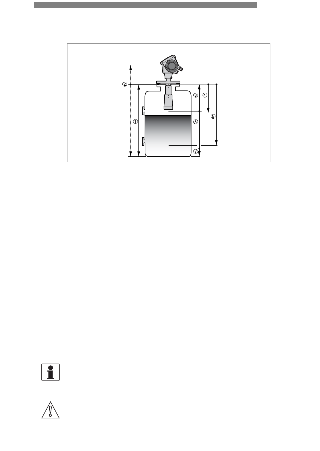
OPERATION 6
61
OPTIWAVE 6300 C
www.krohne.com04/2009 - 4000547001 - HB OPTIWAVE 6300 R01 en
For further information, refer to
Function description
on page 46, table C. Advanced setup. This
gives more data on the menu items.
6.4.6 Level measurement
The device displays level measurements when an output is set to level. Menu items
related to level measurement are:
•output function (C.3.1 or C.4.1).
•tank height (C.1.2).
•blocking distance (C.1.9).
Use the silo bottom as the reference point for the 4 and 20 mA current output settings.
The 4 and 20 mA current output settings are the minimum and maximum points of the
measurement scale. You can change the reference point from which level is
measured. Use this menu item:
•tank bottom offset (C.1.11).
Figure 6-5: Distance measurement
1 Tank height (C.1.2)
2 Reference offset (C.1.10)
3 Blocking distance (C.1.9)
4 4 mA setting (C.3.2 or C.4.2)
5 20 mA setting (C.3.3 or C.4.3)
6 Maximum effective measuring range
7 Non-measurement zone
INFORMATION!
If you move the reference point below the silo bottom, add this value when give a level for the 4
and 20 mA current output settings. If you move the reference point above the silo bottom,
subtract this value when give a level for the 4 and 20 mA current output settings.
CAUTION!
If the level for the 20 mA is set in the blocking distance, the device will not be able to use the full
current output range.
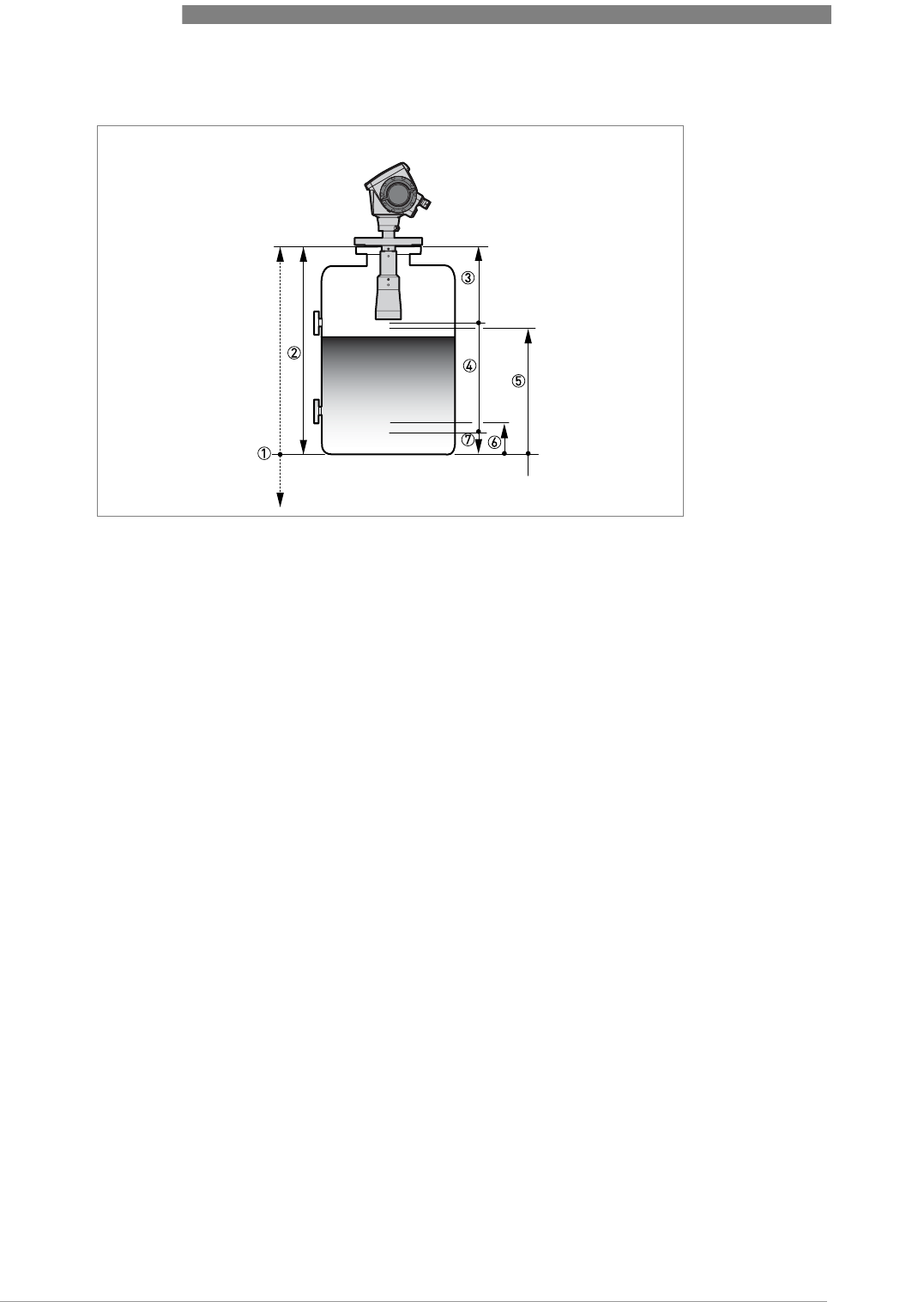
6 OPERATION
62
OPTIWAVE 6300 C
www.krohne.com 04/2009 - 4000547001 - HB OPTIWAVE 6300 R01 en
For further information, refer to
Function description
on page 46, table C. Advanced setup. This
gives more data on the menu items.
Figure 6-6: Level measurement
1 Tank bottom offset (C.1.11)
2 Tank height (C.1.2)
3 Blocking distance (C.1.9)
4 Maximum effective measuring range
5 20 mA setting (C.3.3 or C.4.3)
6 4 mA setting (C.3.2 or C.4.2)
7 Non-measurement zone
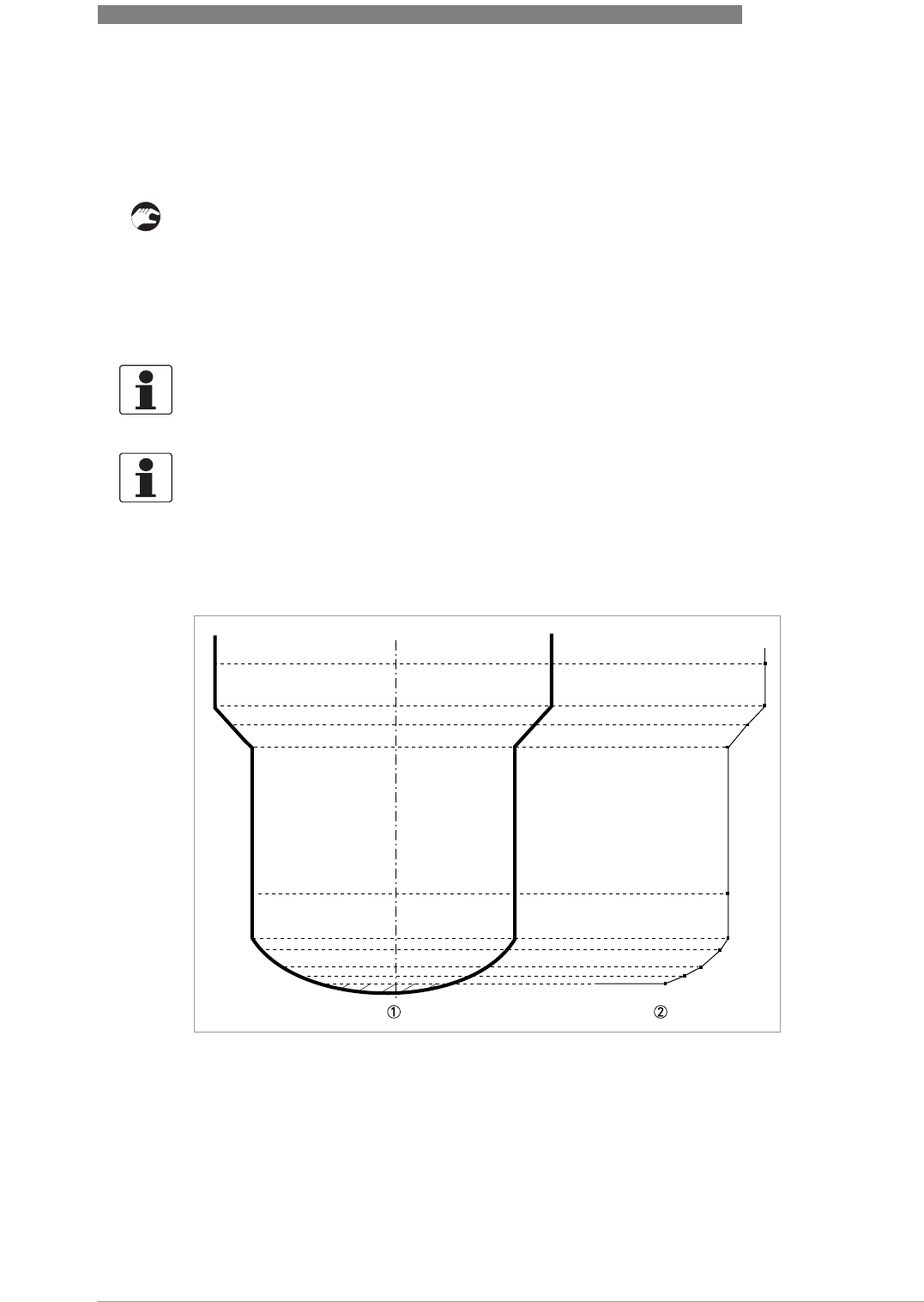
OPERATION 6
63
OPTIWAVE 6300 C
www.krohne.com04/2009 - 4000547001 - HB OPTIWAVE 6300 R01 en
6.4.7 How to configure the device to measure volume or mass
The device can be configured to measure volume or mass. The procedure for doing this is given
in the device's Quick Setup menu.
How to create a volume or mass table.
• Go to Supervisor > Quick setup > Setup mode > Conversion.
• Complete all the steps in the setup procedure.
The device creates a table of up to 50 pairs of data (level - volume or level - mass). The reference
point for the table is the silo bottom (as given in menu item C.1.2 Tank height.).
INFORMATION!
You can also create customized length and conversion units (free units) in the Conversion setup
procedure.
INFORMATION!
When you create a table, get more conversion data for parts of the silo where there are:
•
Surfaces with curves.
•
Sudden changes in the cross section.
This will make volume measurement more accurate.
Figure 6-7: A plot of points for a volume or mass table
1 Silo with reference points
2 Silo model with plotted points
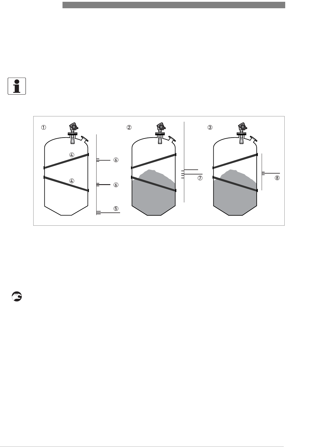
6 OPERATION
64
OPTIWAVE 6300 C
www.krohne.com 04/2009 - 4000547001 - HB OPTIWAVE 6300 R01 en
6.4.8 How to use the empty spectrum function to filter parasite signals
If the device measures level in a silo that contains obstructions (ladder, supports etc.), these
objects can cause radar signal interference. You can use the empty spectrum function in the
device's Quick Setup menu to filter radar signal interference.
• Get access to the Main Menu of the supervisor mode.
iFor more data, refer to
How to get access to the supervisor mode
on page 41.
• Go to Main Menu > Quick Setup > Setup Mode > Empty Spectrum.
• Is the tank completely full? Select Yes or No and then press ^.
iIf you select Yes, the device will not do the empty spectrum scan. Empty the tank and repeat
the procedure.
• Are all the moving parts switched on? Select Yes or No and then press ^.
• Is your tank partially filled or completely empty? Select Partially filled or Empty and then
press ^.
• Do you want to use the average value or the maximum value? Select Average or Maximum and
then press ^.
iUse the maximum for tanks that have moving parts. Use the average value for tanks that do
not have moving parts. The device will do an empty spectrum scan and then display the
results on the signal screen.
• Press ^. Do you want to save the spectrum. Select Yes or No and then press ^.
INFORMATION!
We recommend that you do an empty spectrum scan when the silo is empty and all the moving
parts are switched on.
Figure 6-8: How to filter radar signal interference
1 Empty silo before the empty spectrum scan (with a graph of reflections shown)
2 Partially filled silo before the empty spectrum scan (with a graph of reflections shown)
3 Partially filled silo after the empty spectrum scan (with a graph of reflections shown)
4 Silo bottom signal
5 Support beam signals
6 Support beam signals (interference signals) before the empty spectrum scan
7 Bad (mixed) signals of the solid and the support beam before the empty spectrum scan
8 Good signal of the solid after the empty spectrum scan

OPERATION 6
65
OPTIWAVE 6300 C
www.krohne.com04/2009 - 4000547001 - HB OPTIWAVE 6300 R01 en
iIf you select Yes, the device will use the empty spectrum scan results to filter out radar
signal interference.
6.4.9 How to measure correctly in silos with curved or conical bottoms
It is possible that the device cannot find the bottom of the silo if it is installed in a silo with a
dish-shaped or conical bottom. The form of the silo bottom causes a delayed radar reflection and
the device will display the error message "Measurement is lost in the tank bottom".
You can offset the tank bottom reference point to find the delayed radar reflection. Obey the
instructions that follow:
• Empty the silo.
• Increase the tank height in menu C.1.2.
• Go to the signal screen in operator mode.
iYou will see a graph of reflections.
• Press > to move the cursor to the reflection with the largest amplitude (given in dB).
• Make a note of the distance of the reflection measured by the device.
iThe distance to the reflection will be the new silo height.
• Subtract the distance to the reflection from the true silo height.
• Go to Supervisor > Advanced setup > Installation setup > Tank bottom offset.
• Type in the difference you calculated as a negative value.
iA negative value will move the reference point above the silo bottom (as given in menu item
C.1.2 Tank height).
• Press ^.
• Press > and U (Esc) at the same time to exit to the "save settings" window.
• Select Save and press ^.
iThe device will go back to operator mode.
INFORMATION!
For more data on empty spectrum scans, refer to Function description on page 46
- table A.
Quick Setup (item A.1.3).
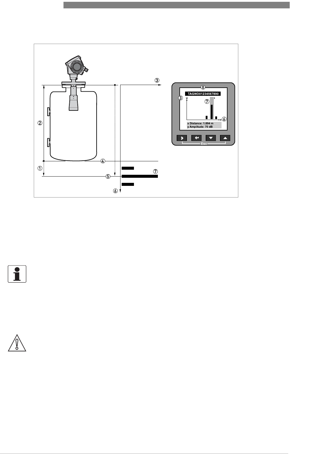
6 OPERATION
66
OPTIWAVE 6300 C
www.krohne.com 04/2009 - 4000547001 - HB OPTIWAVE 6300 R01 en
6.5 Service mode
Service personnel use this mode to change advanced settings, particularly for difficult
applications.
This mode is locked with a password. Only approved persons are permitted to have the password
for the service menu. Please contact your local sales office for further information.
Figure 6-9: Signal screen and the silo bottom reflection
1 Tank bottom offset (menu item C.1.11)
2 Tank height (menu item C.1.2)
3 Signal amplitude (in dB)
4 True position of the silo bottom
5 Offset position of the silo bottom
6 Distance of the reflection from the device flange
7 Delayed reflection of the silo bottom
8 Signal screen on the device display
INFORMATION!
For more data on menu items, refer to Function description on page 46
, table C. Advanced
setup.
CAUTION!
If you are not an authorized service technician, do not change any values in the service mode
menu.
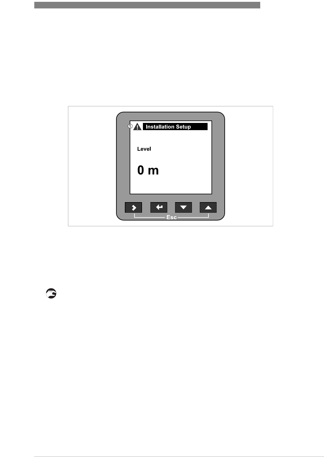
OPERATION 6
67
OPTIWAVE 6300 C
www.krohne.com04/2009 - 4000547001 - HB OPTIWAVE 6300 R01 en
6.6 Errors
6.6.1 General information
Indication of errors
When the device senses an error condition, it displays an error symbol in the top left corner of
the display screen.
Enter the supervisor mode to either:
•Do an error status check, or
•Read the error records and get more data about the error.
How to check the error status
• Enter supervisor mode.
• Go to Test > Information > Measurement quality.
iThis shows the status of device errors at this time. A "tick" symbol next to an error in the
list shows that this error is active and may have an unwanted effect on the device.
• For solutions to the problem, refer to
Error handling
on page 70.
Figure 6-10: Indication of errors
1 Error/ warning symbol
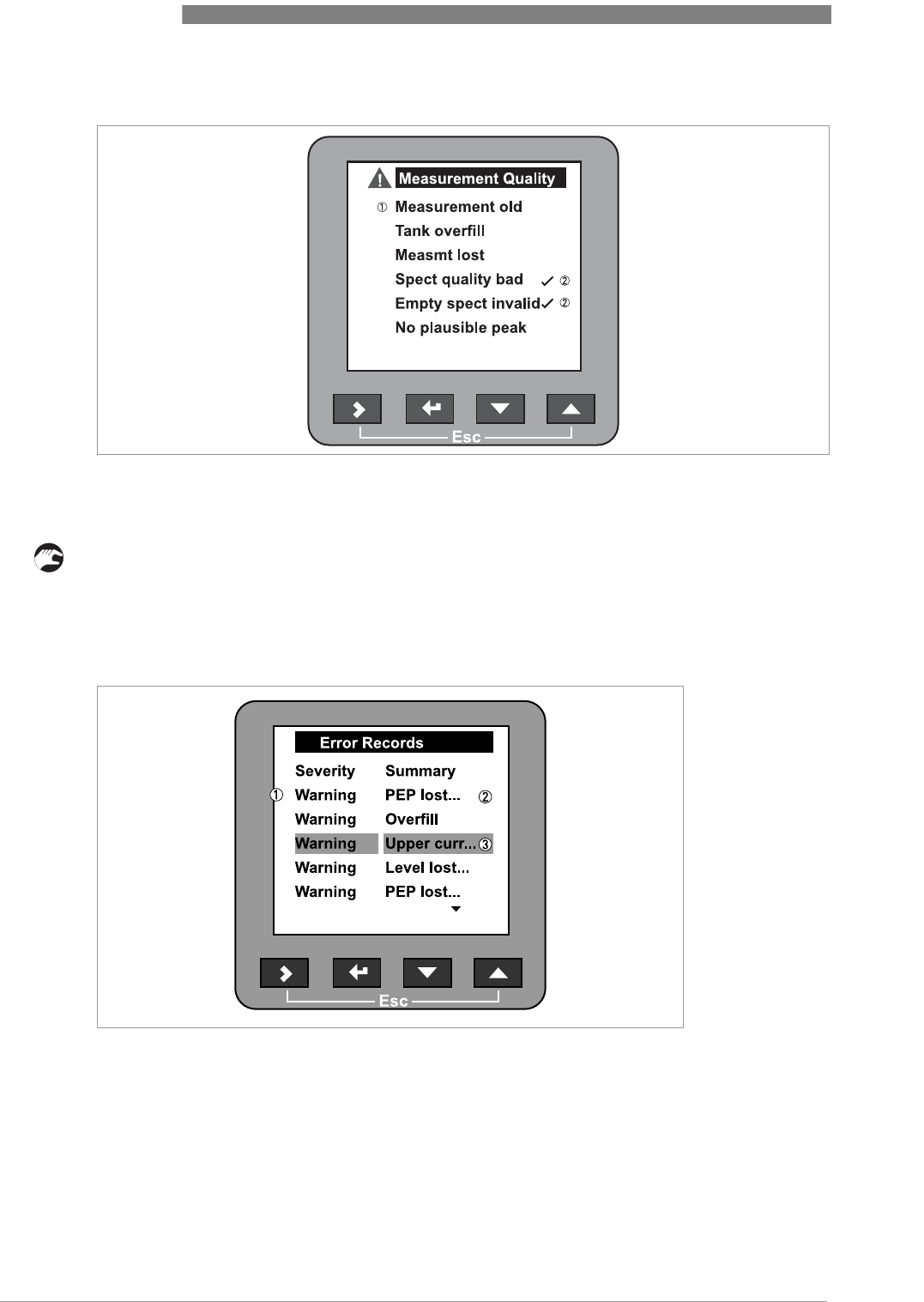
6 OPERATION
68
OPTIWAVE 6300 C
www.krohne.com 04/2009 - 4000547001 - HB OPTIWAVE 6300 R01 en
How to find the error records
• Enter supervisor mode.
• Go to Test > Information > Error records.
• Use V and U to scroll the error list. There are 5 error messages per page.
Figure 6-11: Measurement quality in supervisor mode
1 Type of error.
2 Error "active"
Figure 6-12: Error records in supervisor mode
1 Type of error.
2 Short description of the error
3 Selection bar
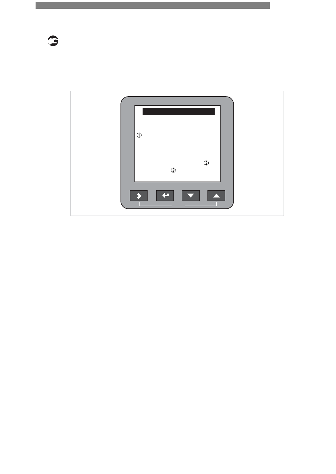
OPERATION 6
69
OPTIWAVE 6300 C
www.krohne.com04/2009 - 4000547001 - HB OPTIWAVE 6300 R01 en
How to get more data about the error (error records function)
• Select an error log and press ^ to read the help text.
iTypical data is given in the illustration that follows.
• For solutions to the problem, refer to
Error handling
on page 70.
The time since the error occurred is measured in Days:Hours:Minutes:Seconds. It only includes
the time when the device is energized. The error is saved in the memory of the device when it is
switched off. The counter continues when the device is switched back on.
The error symbol is no longer displayed after you read the error record.
Figure 6-13: Description of the error
1 Description of the error
2 Time since error occurred in Days:Hours:Minutes:Seconds
3 Type of error
Esc
Error Records
Upper current output
has saturated.
Time:
Warning :34:9:39:0

6 OPERATION
70
OPTIWAVE 6300 C
www.krohne.com 04/2009 - 4000547001 - HB OPTIWAVE 6300 R01 en
6.6.2 Error handling
Types of error message
Description of errors and corrective actions
Type of error Error
code
Description
Error EIf an error message is displayed in the error record (menu
item B.2.6), the measured value is not correct. The output
current goes to the value set in menu items C.3.5 Error
Handling (Ouput 1) and C.4.5 Error Handling (Output 2). For
more data; refer to
C. Advanced setup
on page 52.
Warning WIf a warning message continues, the measured value will no
longer be correct.
Error Message Error
code
Description Corrective action
Current output
Current output saturated at
maximum value. WThe output is at its maximum
output value (20 or 20.5 mA)
because the measured value
is now out of the
measurement range.
Fill the silo or remove some
of the product until the level
is back in the configured
range.
Current output saturated at
minimum value. WThe output is at its minimum
output value (4 or 3.8 mA)
because the measured value
is now out of the
measurement range.
Fill the silo or remove some
of the product until the level
is back in the configured
range.
External influences
Temperature out of range for
NAND Flash WThe ambient temperature is
outside the given range. This
can cause loss or corruption
of data.
Switch off the device until the
ambient temperature is back
in the given range. If the
problem continues, contact
the supplier.

OPERATION 6
71
OPTIWAVE 6300 C
www.krohne.com04/2009 - 4000547001 - HB OPTIWAVE 6300 R01 en
Self-test manager
Self Test has failed EThe device's self-test failed.
This can occur if the ambient
temperature is not between -
40...+80°C / -40...175°F.
Energize the device when the
ambient temperature is
between -40...+80°C / -
40....+175°F. If the device
does not operate correctly,
contact the supplier.
Measuring status
Measurement is old WThis is a temporary error
message. If the device cannot
get a measurement in this
time limit, the displayed
measurement is no longer
correct. The voltage is
possibly too low. If the device
continues to show the
message "spectrum quality is
bad", then this message is
also shown.
Check the voltage at the
device terminals. Refer also
to the error message
"Spectrum quality is bad".
Level has reached the
blocking distance (silo
overfill)
WThe level is in the blocking
distance. There is a risk that
the product will overflow
and/or cover the device.
Remove some of the product
until the level is below the
blocking distance.
Measurement is lost in the
tank bottom WThe silo is possibly empty.
The device will display the silo
bottom measurement.
If you fill the silo, the device
will measure again.
The device got the last valid
measurement near to the silo
bottom, but it can no longer
find the signal. It is possible
that the device cannot find the
bottom of the silo if it is
installed in a silo with a dish-
shaped (DIN28011 or similar)
or conical bottom. The form
of the silo bottom causes a
delayed radar reflection and
the device will display the
error message
"Measurement is lost in the
tank bottom". The device will
display the silo bottom
measurement.
Follow the instructions on
page 65.
Electronics failures
Microwave check failed EA microwave board check
failed. If the problem continues,
contact the supplier.
Peripheral Failure EHardware peripheral devices
on the DSP board failed. If the problem continues,
contact the supplier.

6 OPERATION
72
OPTIWAVE 6300 C
www.krohne.com 04/2009 - 4000547001 - HB OPTIWAVE 6300 R01 en
Peak and spectrum
Spectrum quality is bad WThe quality of the spectrum is
poor. If this message is
temporarily shown, this will
not affect the performance of
the device. If this message is
continuously shown, the
measured values can be
incorrect. The error message
"Measurement is old" will
then be displayed. Possible
causes are internal silo
elements.
Check the device, silo and the
process. Reconfigure the
device and record a new
empty spectrum. Follow the
instructions on page 64. If
necessary, contact the
supplier.
Empty spectrum is invalid WThe Empty Spectrum stored
in the device does not agree
with the installation. If you
change the device
configuration (tank height
etc.), this message will be
displayed. The recorded
empty spectrum will not be
used by the device while this
error message is displayed.
Check the device, silo and the
process. Reconfigure the
device and record a new
empty spectrum. Follow the
instructions on page 64. If
necessary, contact the
supplier.
Plausible peak is not
available WThe signal peak is not found
within the measuring window
that filters the signals
received by the antenna. The
measurement is not correct.
The device will automatically
increase this window to find
the correct signal.
Check the device, silo and the
process. Reconfigure the
device and record a new
empty spectrum. Follow the
instructions on page 64. If
necessary, contact the
supplier.
Software error
Unable to load DSP firmware EThe DSP Firmware did not
download correctly to the
DSP board.
Restart the device. If the
problem continues, contact
the supplier.

SERVICE 7
73
OPTIWAVE 6300 C
www.krohne.com04/2009 - 4000547001 - HB OPTIWAVE 6300 R01 en
7.1 Periodic maintenance
No maintenance is necessary.
7.2 How to clean the top surface of the device
Obey these instructions:
• Keep the thread of the terminal compartment cover clean.
• If dirt collects on the device, clean it. Wipe the plastic sun cover with a damp cloth.
WARNING!
Do not let more than 5 mm / 0.2
¨
of dust collect on the top surface of the device. This is a possible
source of ignition in a potentially explosive atmosphere.
DANGER!
Risk of electrostatic discharge from the blue plastic sun cover.

7 SERVICE
74
OPTIWAVE 6300 C
www.krohne.com 04/2009 - 4000547001 - HB OPTIWAVE 6300 R01 en
7.3 How to clean horn antennas under process conditions
If it is possible that there will be build-up, a purging option is available for horn antennas.
For more data, refer to the table that follows:
How to use the purge
WARNING!
Purge the antenna with a dry gas that is applicable to the process.
CAUTION!
Purge the antenna at intervals to make sure that the inner surface of the antenna stays clean
and the device measures accurately.
Process conditions How to use the purge
There is a risk of build-up in the
antenna Continuous use. Use low-pressure, low-flow dry gas to remove dust
from the antenna.
There is a build-up or risk of
build-up in the antenna Purge at intervals. Use compressed air, nitrogen or another dry gas
that is applicable to the process up to 6 bar / 87 psi.

SERVICE 7
75
OPTIWAVE 6300 C
www.krohne.com04/2009 - 4000547001 - HB OPTIWAVE 6300 R01 en
7.4 How to replace device components
7.4.1 Service warranty
Maintenance is not necessary for most applications.
Servicing by the customer is limited by warranty to
•The removal and installation of the signal converter housing. For more data, refer to
How to
turn or remove the signal converter
on page 27.
•The removal and installation of the back end and the front end assembled to the microwave
board.
•The removal and installation of the terminal module.
•The removal and installation of the HMI cover.
This housing can be detached from the flange system under process conditions.
Use only authorized service staff to repair the device.
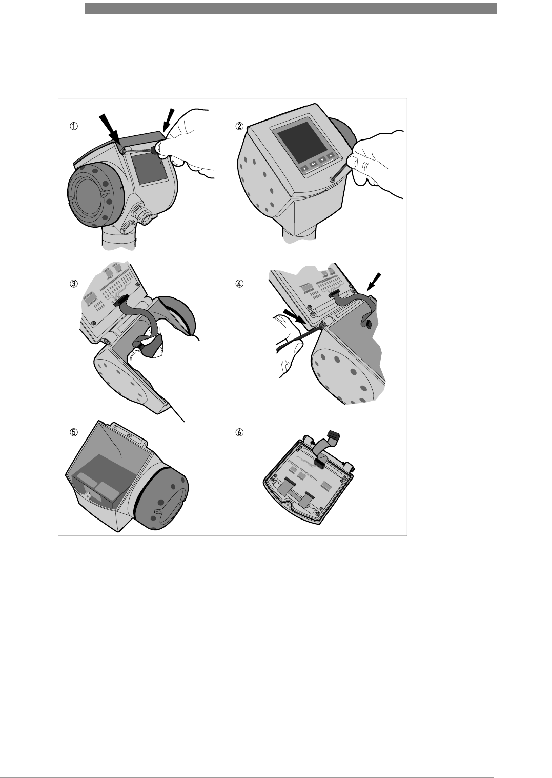
7 SERVICE
76
OPTIWAVE 6300 C
www.krohne.com 04/2009 - 4000547001 - HB OPTIWAVE 6300 R01 en
7.4.2 Replacement of the display cover
Equipment needed (not supplied):
•Slotted tip screwdriver.
•3 mm Allen wrench (for steps 2 and 4).
Figure 7-1: Removal of the device display cover

SERVICE 7
77
OPTIWAVE 6300 C
www.krohne.com04/2009 - 4000547001 - HB OPTIWAVE 6300 R01 en
How to remove the display
1 Remove the 2 pins on the blue sun cover with a slotted tip screwdriver. Remove the sun cover.
2 Loosen the screw on the display screen cover. Open the display.
3 Disconnect the ribbon cable from the back end electronics block.
iKeep the ribbon cable connected to the display screen cover.
4 Remove the 2 screws that keep the display attached to the housing.
5 Keep the remaining assembly and put it into storage. Make sure that the top of the housing
has a protective cover.
6 Send the display to an authorized agent for maintenance.
How to attach the display
• Attach the display. Attach the 2 housing screws.
• Connect the ribbon cable to the back end electronics block.
iMake sure the connector is correctly turned. Do not use force to connect the ribbon cable.
• Close the display. Tighten the screw on the display.
• Attach the sun cover. Attach the 2 pins that keep the sun cover attached to the housing.
WARNING!
Disconnect the power supply
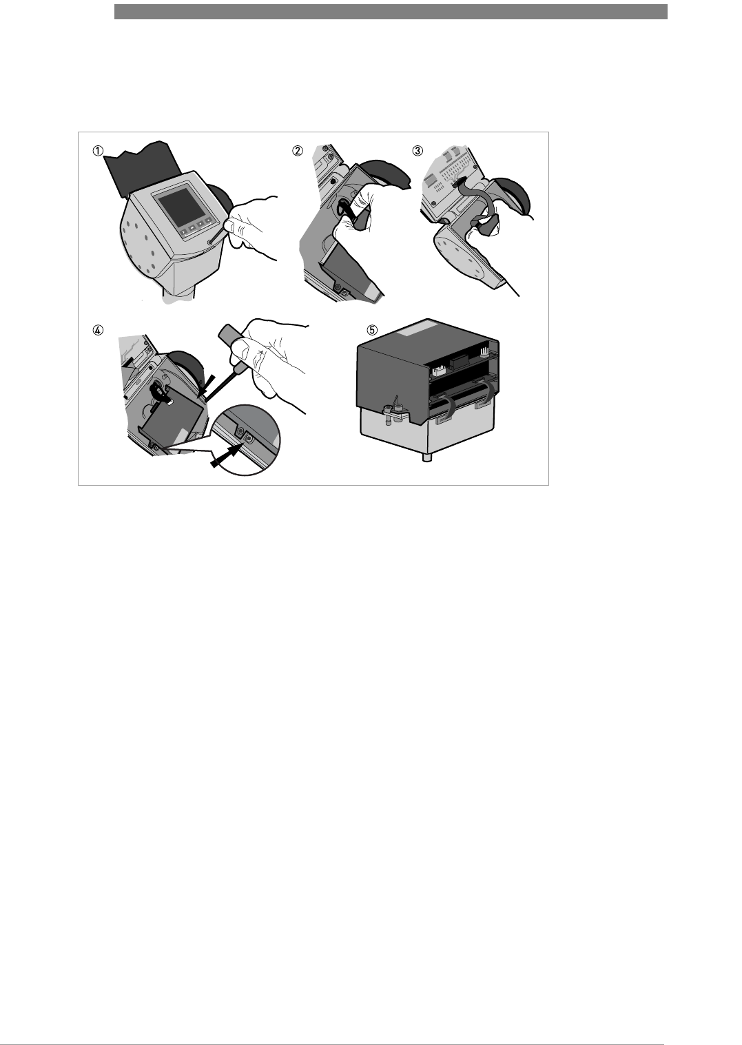
7 SERVICE
78
OPTIWAVE 6300 C
www.krohne.com 04/2009 - 4000547001 - HB OPTIWAVE 6300 R01 en
7.4.3 Replacement of the back end and microwave unit
Equipment needed (not supplied):
•3 mm Allen wrench (for steps 1 and 4).
Figure 7-2: Removal of the back end and microwave unit

SERVICE 7
79
OPTIWAVE 6300 C
www.krohne.com04/2009 - 4000547001 - HB OPTIWAVE 6300 R01 en
How to remove the back end and microwave unit
1 Loosen the screw on the display. Open the display.
2 Disconnect the power supply connector from the electronics block.
3 Disconnect the display ribbon cable from the back end electronics block.
4 Loosen the 2 screws shown in the illustration.
iDo not loosen the other screws. You will disassemble the electronics block into 2 pieces. It
is then difficult to remove these pieces from the housing.
5 Remove the back end and microwave unit from the housing. Send the electronics block to an
authorized agent for maintenance.
How to attach the back end and microwave unit
• Open the display.
• Put the electronics block into the housing. Make sure that the connector engages in the
mating part.
• Tighten the 2 screws to attach the electronics block to the bottom of the housing.
• Connect the display ribbon cable to the back end electronics block.
• Connect power supply connector to the back end electronics block.
• Close the display. Tighten the screw on the display.
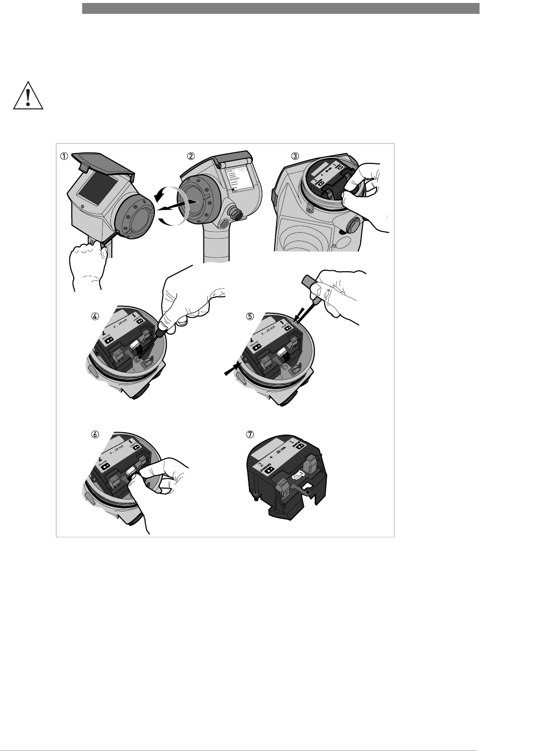
7 SERVICE
80
OPTIWAVE 6300 C
www.krohne.com 04/2009 - 4000547001 - HB OPTIWAVE 6300 R01 en
7.4.4 Replacement of the terminal module
Equipment needed (not supplied):
•3 mm Allen wrench (for step 1).
•TORX T10 wrench (for step 4).
•2.5 mm Allen wrench (for step 5).
WARNING!
Disconnect the power supply.
Figure 7-3: Removal of the terminal module

SERVICE 7
81
OPTIWAVE 6300 C
www.krohne.com04/2009 - 4000547001 - HB OPTIWAVE 6300 R01 en
How to remove the terminal module
1 Loosen the cover stop screw on the terminal compartment cover.
2 Remove the terminal compartment cover.
3 Remove the plastic terminal cover.
4 Loosen the screw for the earth terminal connection.
5 Loosen the 2 screws shown in the illustration.
6 Disconnect the wire connector from the back end electronics compartment.
7 Remove the terminal block from the housing. Send it to an authorized agent for maintenance.
How to attach the terminal module
• Connect the wire connector from the back end electronics compartment.
• Push the wires into the slot below the connector on the terminal block.
• Turn the terminal block one time to twist the wires.
• Put the terminal block into the housing. Make sure that you push the wires away from the
screw holes.
• Attach the terminal block to the housing with 2 screws supplied.
• Attach the earth terminal connection to the housing with the screw supplied.
• Attach the plastic terminal cover.
• Attach the terminal compartment cover.
• Tighten the cover stop screw.
WARNING!
If you do not push the wires away from the screw holes when you attach the terminal block, there
is a risk of damage to the wires.
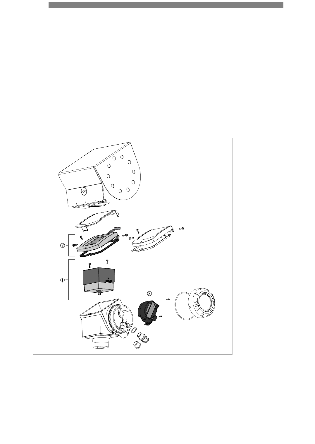
7 SERVICE
82
OPTIWAVE 6300 C
www.krohne.com 04/2009 - 4000547001 - HB OPTIWAVE 6300 R01 en
7.5 Spare parts availability
The manufacturer adheres to the basic principle that operational spare parts for each device or
each important accessory part will be kept available for a period of 10 (ten) years after delivery of
the last production run for that device.
Operational spare parts are defined as parts that are subject to faults in normal operation.
7.5.1 List of spare parts
We supply spare parts and accessories for this device. When you order a spare part or
accessory, please give the reference numbers that follow:
Figure 7-4: Spare parts

SERVICE 7
83
OPTIWAVE 6300 C
www.krohne.com04/2009 - 4000547001 - HB OPTIWAVE 6300 R01 en
Part numbers for spare parts
Item number Description Quantity Part reference
1Combined backend and high-frequency modules 1 1F2139580100
Screws for the combined back end and HF modules 2F3177360000
2HMI cover and cable 2 1XF6340000000050300
3Terminal module with 1 output (non-Ex) 1F2139620200
Terminal module with 1 output (Ex ia) 1F2139620100
Terminal module with 1 output (Ex d [ia]) 1F2139950100
Terminal module with 2 outputs (non-Ex) 1F2139630200
Terminal module with 2 outputs (Ex ia) 1F2139630100
Terminal module with 2 outputs (Ex d [ia]) 1F2139640100
Screws for the terminal module 2F3177350000
1the customer must send the original back end and HF module to the repair centre. Refer to the replacement procedure
in this section.
2this reference includes the gasket and screws
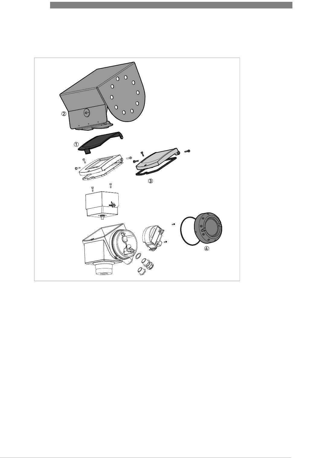
7 SERVICE
84
OPTIWAVE 6300 C
www.krohne.com 04/2009 - 4000547001 - HB OPTIWAVE 6300 R01 en
7.5.2 List of accessories
Figure 7-5: Accessories

SERVICE 7
85
OPTIWAVE 6300 C
www.krohne.com04/2009 - 4000547001 - HB OPTIWAVE 6300 R01 en
Part numbers for accessories
Item number Description Quantity Part reference
1Plastic sun cover 1F3179980000
Pins for the plastic sun cover 2F3179990000
2Stainless steel weather protection 1F2096340000
3Blind cover (with a gasket and screws) 1F3177240100
Gasket for the blind cover 1F3177420000
Hinge screws for the blind cover 2F3177340000
Lock screw for the blind cover 1F3177360000
4Wiring compartment cover 1F3177260100
Gasket for the wiring compartment cover 1F5091150000
n/a Converter VIATOR RS232 / HART® 1 1F50919500000
Converter USB / HART® 1 1F50779300000
n/a 2° PP slanted flange accessory for:
DN80 PN40 flange 1F3190190000
DN100 PN16 flange 1F3190190100
DN100 PN40 flange 1F3190190200
DN150 PN16 flange 1F3190190300
DN150 PN40 flange 1F3190190400
2¨ 150LBS flange 1F3190220000
2¨ 300LBS flange 1F3190220100
3¨ 150LBS flange 1F3190220200
3¨ 300LBS flange 1F3190220300
4¨ 150LBS flange 1F3190220400
4¨ 300LBS flange 1F3190220500
6¨ 150LBS flange 1F3190220600
6¨ 300LBS flange 1F3190220700
8¨ 150LBS flange 1F3190220800
40A 10K flange 1F3190230000
50A 10K flange 1F3190230100
80A 10K flange 1F3190230200
100A 10K flange 1F3190230300
1for HART® or PACTware™ communication

7 SERVICE
86
OPTIWAVE 6300 C
www.krohne.com 04/2009 - 4000547001 - HB OPTIWAVE 6300 R01 en
7.6 Availability of services
The manufacturer offers a range of services to support the customer after expiration of the
warranty. These include repair, technical support and training.
7.7 Returning the device to the manufacturer
7.7.1 General information
This device has been carefully manufactured and tested. If installed and operated in accordance
with these operating instructions, it will rarely present any problems.
INFORMATION!
For more precise information, please contact your local representative.
CAUTION!
Should you nevertheless need to return a device for inspection or repair, please pay strict
attention to the following points:
•
Due to statutory regulations on environmental protection and safeguarding the health and
safety of our personnel, manufacturer may only handle, test and repair returned devices that
have been in contact with products without risk to personnel and environment.
•
This means that the manufacturer can only service this device if it is accompanied by the
following certificate (see next section) confirming that the device is safe to handle.
CAUTION!
If the device has been operated with toxic, caustic, flammable or water-endangering products,
you are kindly requested:
•
to check and ensure, if necessary by rinsing or neutralizing, that all cavities are free from
such dangerous substances,
•
to enclose a certificate with the device confirming that is safe to handle and stating the
product used.

SERVICE 7
87
OPTIWAVE 6300 C
www.krohne.com04/2009 - 4000547001 - HB OPTIWAVE 6300 R01 en
7.7.2 Form (for copying) to accompany a returned device
7.8 Disposal
Company: Address:
Department: Name:
Tel. no.: Fax no.:
Manufacturer's order no. or serial no.:
The device has been operated with the following medium:
This medium is: water-hazardous
toxic
caustic
flammable
We checked that all cavities in the device are free from such
substances.
We have flushed out and neutralized all cavities in the
device.
We hereby confirm that there is no risk to persons or the environment through any residual media
contained in the device when it is returned.
Date: Signature:
Stamp:
CAUTION!
Disposal must be carried out in accordance with legislation applicable in your country.
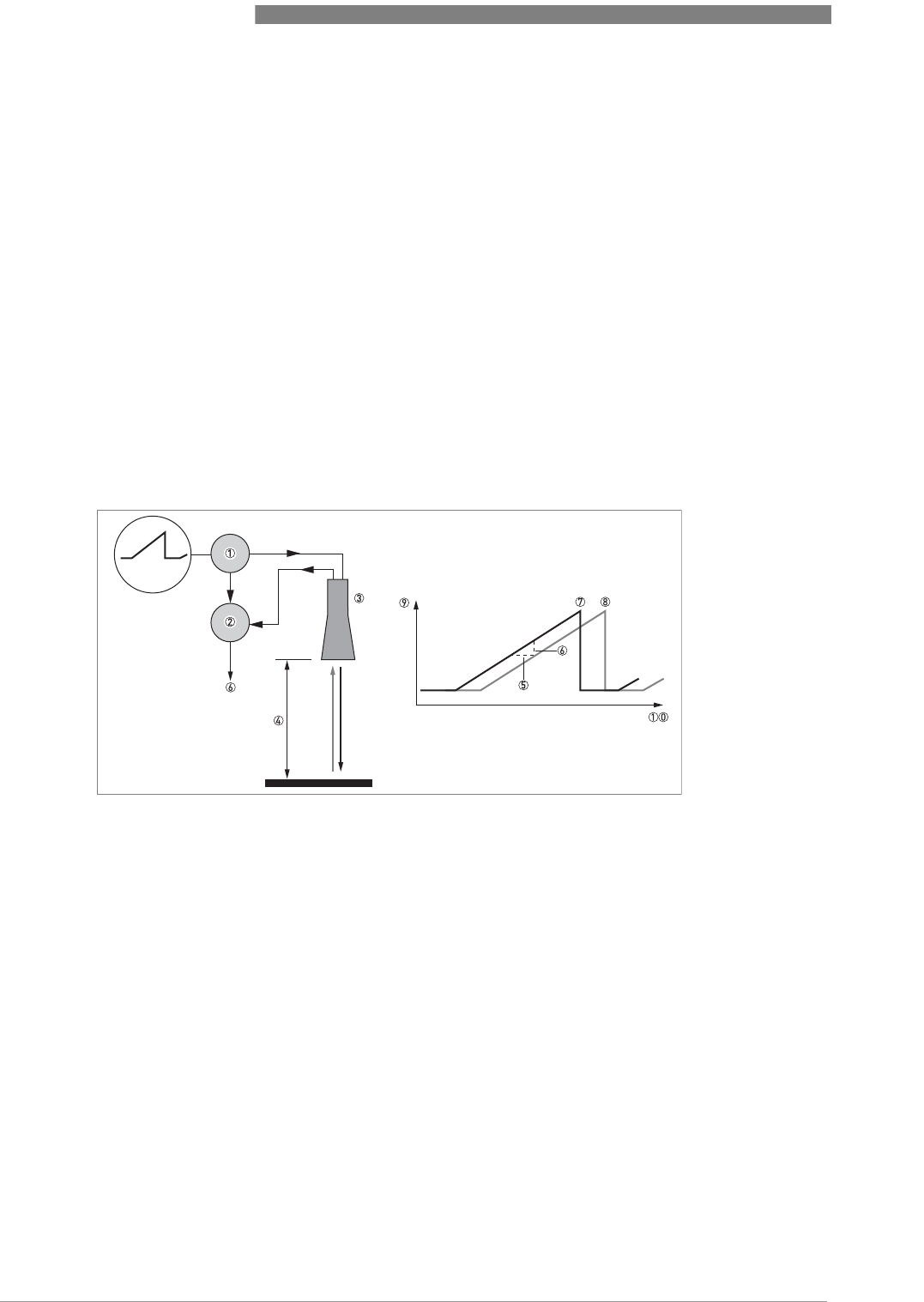
8 TECHNICAL DATA
88
OPTIWAVE 6300 C
www.krohne.com 04/2009 - 4000547001 - HB OPTIWAVE 6300 R01 en
8.1 Measuring principle
A radar signal is emitted via an antenna, reflected on the product surface and received after a
time t. The radar principle used is FMCW (Frequency Modulated Continuous Wave).
The FMCW-radar transmits a high frequency signal whose frequency increases linearly during
the measurement phase (called the frequency sweep). The signal is emitted, reflected on the
measuring surface and received with a time delay, t. Delay time, t=2d/c, where d is the distance
to the product surface and c is the speed of light in the gas above the product.
For further signal processing the difference Δf is calculated from the actual transmit frequency
and the receive frequency. The difference is directly proportional to the distance. A large
frequency difference corresponds to a large distance and vice versa. The frequency difference Δf
is transformed via a Fourier transformation (FFT) into a frequency spectrum and then the
distance is calculated from the spectrum. The level results from the difference between tank
height and measuring distance.
Figure 8-1: Measuring principle of FMCW radar
1 Transmitter
2 Mixer
3 Antenna
4 Distance to product surface, where change in frequency is proportional to distance
5 Differential time delay, Δt
6 Differential frequency, Δf
7 Frequency transmitted
8 Frequency received
9 Frequency
10 Time

TECHNICAL DATA 8
89
OPTIWAVE 6300 C
www.krohne.com04/2009 - 4000547001 - HB OPTIWAVE 6300 R01 en
8.2 Technical data
INFORMATION!
•
The following data is provided for general applications. If you require data that is more
relevant to your specific application, please contact us or your local representative.
•
Additional information (certificates, special tools, software,...) and complete product
documentation can be downloaded free of charge from the website (Downloadcenter).
Measuring system
Measuring principle 2-wire loop-powered level transmitter; K-band FMCW radar
Application range Level measurement of powders and granulates
Primary measured value Δf (change in frequency) between the emitted and received signal
Secondary measured value Distance, level, volume and reflectivity
Design
Construction The measurement system consists of a measuring sensor (antenna) and a signal
converter which is only available in a compact version
Standard Antenna purging system for horn antenna (supplied with ¼ NPTF connection)
Options Integrated LCD display with sun cover (-20..+60°C / -4…+140°F);
if the ambient temperature is not in these limits, the display switches off
2nd current output
PTFE/PP flange plate protection
(for Drop antenna without antenna extensions only)
Accessories Weather protection
Antenna extensions of 105 mm / 4.1¨ length (Max. length for Drop antenna versions:
525 mm / 20.7¨. On request for antennas made of Hastelloy® C-22.)
2° PP slanted flange (for all antennas)
Max. measuring range 80 m / 260 ft
Depends on the antenna option, dielectric constant of the product and installation
type. Refer also to "Antenna selection".
Min. tank height 0.2 m / 8¨
Dead zone Antenna extension length + antenna length + 0.3 m / 12¨
Beam angle of antenna Horn DN80 / 3¨: 10°
Horn DN100 / 4¨: 8°
Drop DN80 / 3¨: 8°
Drop DN150 / 6¨: 4°
Display and user interface
Display LCD display
9 lines, 160 x 160 pixels in 8-step greyscale with 4-button keypad
Interface languages English, German, French, Italian, Spanish, Portuguese, Japanese, Chinese
(Mandarin) and Russian
Measurement accuracy
Resolution 1 mm / 0.04¨
Repeatability ±5 mm / ±0.2¨
Accuracy ±10 mm / ±0.4¨, when distance < 10 m / 33 ft;
±0.1% of measured distance, when distance > 10 m / 33 ft

8 TECHNICAL DATA
90
OPTIWAVE 6300 C
www.krohne.com 04/2009 - 4000547001 - HB OPTIWAVE 6300 R01 en
Reference conditions acc. to EN 60770
Temperature +20°C ±5°C / +70°F ±10°F
Pressure 1013 mbar abs. ±20 mbar / 14.69 psig ±0.29 psig
Relative air humidity 60% ±15%
Target metal plate in an anechoic chamber
Operating conditions
Temperature
Ambient temperature -40…+80°C / -40…+175°F (according to the temperature limits of the gasket
material. Refer to "Materials" in this table.)
Ex i: see supplementary operating instructions or approval certificates
Storage temperature -40…+85°C / -40…+185°F
Flange temperature Horn antenna:
-40…+200°C / -40…+390°F (according to the temperature limits of the gasket
material. Refer to "Materials" in this table.)
Ex i: see supplementary operating instructions or approval certificates
Drop antenna (PTFE):
-40…+150°C / -40…+300°F (according to the temperature limits of the gasket
material. Refer to "Materials" in this table.)
Ex i: see supplementary operating instructions or approval certificates
Drop antenna (PP):
-40…+100°C / -40…+210°F (according to the temperature limits of the gasket
material. Refer to "Materials" in this table.)
Ex i: see supplementary operating instructions or approval certificates
Thermal shock resistance <40°C/s / <72°F/s
Pressure
Operating pressure Drop antenna (PP):
-1…16 bar / -14.5…232 psig; subject to process connection used and flange
temperature
All other antennas:
-1…40 bar / -14.5…580 psig; subject to process connection used and flange
temperature
Other conditions
Dielectric constant (εr) ≥1.5
Vibration resistance IEC 60068-2-6 and EN 50178 (10...57 Hz: 0.075 mm / 57...150 Hz:1g)
Protection category IP 67 equivalent to NEMA 6-6X
Maximum rate of change 10 m/min / 33 ft/min
Installation conditions
Process connection size The process connection should be larger than the antenna diameter.
If the process connection on the instrument is smaller than the antenna, either:
- provide the means to adapt the instrument to a larger process connection on the
silo (for example, a plate with a slot), or
- use the same process connection, but remove the antenna from the instrument
before installation and fit it from inside the silo
Process connection position Make sure that there are not any obstructions directly below the process
connection for the instrument
Dimensions and weights Refer to "Technical data: Dimensions and weights"

TECHNICAL DATA 8
91
OPTIWAVE 6300 C
www.krohne.com04/2009 - 4000547001 - HB OPTIWAVE 6300 R01 en
Materials
Housing Standard: Aluminium
Option: Stainless steel (1.4404 / 316L)
Wetted parts, including antenna Standard for Horn antenna: Stainless steel (1.4404 / 316L)
Option for Horn antenna: Hastelloy® C-22 (2.4602) 1
Standard for Drop antenna: PTFE; PP - a PP or PTFE flange plate option is also
available
Process fitting Standard: Stainless steel (1.4404 / 316L) - a PP or PTFE flange plate option is also
available for Drop antenna
Option: Hastelloy® C-22 (2.4602)
Gaskets FKM/FPM (-40…+200°C / -40…+390°F); Kalrez® 6375 (-20…+200°C / -4…+390°F);
EPDM (-40°C…+150°C / -40…+300°F) 2
Feedthrough Standard: PEI (-40...+200°C / -40...+390°F)
Option: Metaglas® (-30...+200°C / -22...+390°F - for horn antennas only) 3
Weather protection (Option) Stainless steel (1.4301 / 304)
Process connections
Thread G 1½; NPT 1½
Flange version
EN DN80…150 in PN40 / PN16
ASME 3¨…8¨ in 150 lbs / 300 lbs
JIS 80…100A in 10K
Electrical connections
Power supply Terminals output 1 - Non-Ex / Ex i:
14…30 VDC; min./max. value for an output of 22 mA at the terminal
Terminals output 1 - Ex d:
20…36 VDC; min./max. value for an output of 22 mA at the terminal
Terminals output 2 - Non-Ex/ Ex i/ Ex d:
10…30 VDC; min./max. value for an output of 22 mA at the terminal (additional
power supply needed - output only)
Cable entry M20x1.5; NPT ½
G ½ (not for FM- and CSA-approved devices)
M25x1.5 (for stainless steel housings only)
Cable gland Standard: none
Options: M20x1.5 (for non-Ex and Ex -approved devices with M20x1.5 and M25x1.5
cable entries); others are available on request
Cable entry capacity (terminal) 0.5…1.5 mm²
Input and output
Output signal (Output 1) 4…20 mA HART® or 3.8…20.5 mA acc. to NAMUR NE 43 4
Output signal (Output 2 -
optional) 4…20 mA (no HART® signal) or 3.8…20.5 mA acc. to NAMUR NE 43
Resolution ±3 µA
Temperature drift Typically 25 ppm/K
Error signal High: 22 mA; Low: 3.6 mA acc. to NAMUR NE 43

8 TECHNICAL DATA
92
OPTIWAVE 6300 C
www.krohne.com 04/2009 - 4000547001 - HB OPTIWAVE 6300 R01 en
Approvals and certification
CE This device fufills the statutory requirements of the EC directives. The
manufacturer certifies successful testing of the product by applying the CE mark.
Explosion protection
ATEX ATEX II G 1, 1/2, 2 Ex ia IIC T6...T3;
ATEX II D 1, 1/2, 2 Ex iaD 20 or Ex iaD 20/21 or Ex iaD 21 IP6X T65°C...T90°C;
ATEX II G 1/2, 2 Ex d [ia] IIC T6...T3;
ATEX II D 1/2, 2 Ex tD[iaD] A21/20 or Ex tD[iaD] A21 IP6X T65°C...T90°C
IECEx (pending) Zone 0 Ex ia IIC T6…T3; Ex iaD 20 IP6X T65°C…T 90°C
FM or CSA - Dual Seal-approved
(available in Q4/2009) NEC 500/ CEC:
Cl. I, Div. 1, Gr. ABCD (IS);
Cl. I, Div. 1, Gr. ABCD (FM only) (XP);
Cl. I, Div. 2, Gr. ABCD (XP/NI);
Cl. II, Div. 1, Gr. EFG; Cl. III (FM only) (XP);
Cl. II, Div. 1, Gr. EFG; Cl. III (IS);
Cl. II/III, Div . 2, Gr. FG (XP/NI)
NEC 505/ CEC:
Cl. I, Zone 0 AEx ia Gr. IIC (CSA: Ex ia) (IS);
Cl. I, Zone 1 AEx d [ia] Gr. IIC (XP);
Cl. I, Zone 2, AEx nA [ia], Gr. IIC (CSA: Ex nA [ia]) (IS)
Other standards and approvals
EMC EMC Directive 2004 / 108 / EC and 93 / 68 / EEC in conjunction with EN 61326-
1 (2006).
LVD Low-Voltage Directives 2006 / 95 / EC and 93 / 68 / EEC in conjunction with
EN 61010-1 (2001).
NAMUR NAMUR NE 21 Electromagnetic Compatibility (EMC) of Industrial Process and
Laboratory Control Equipment
NAMUR NE 43 Standardization of the Signal Level for the Failure Information of
Digital Transmitters
1Hastelloy® is a registered trademark of Haynes International, Inc.
2Kalrez® is a registered trademark of DuPont Performance Elastomers L.L.C.
3Metaglas® is a registered trademark of Herberts Industrieglas, GMBH & Co., KG
4HART® is a registered trademark of the HART Communication Foundation
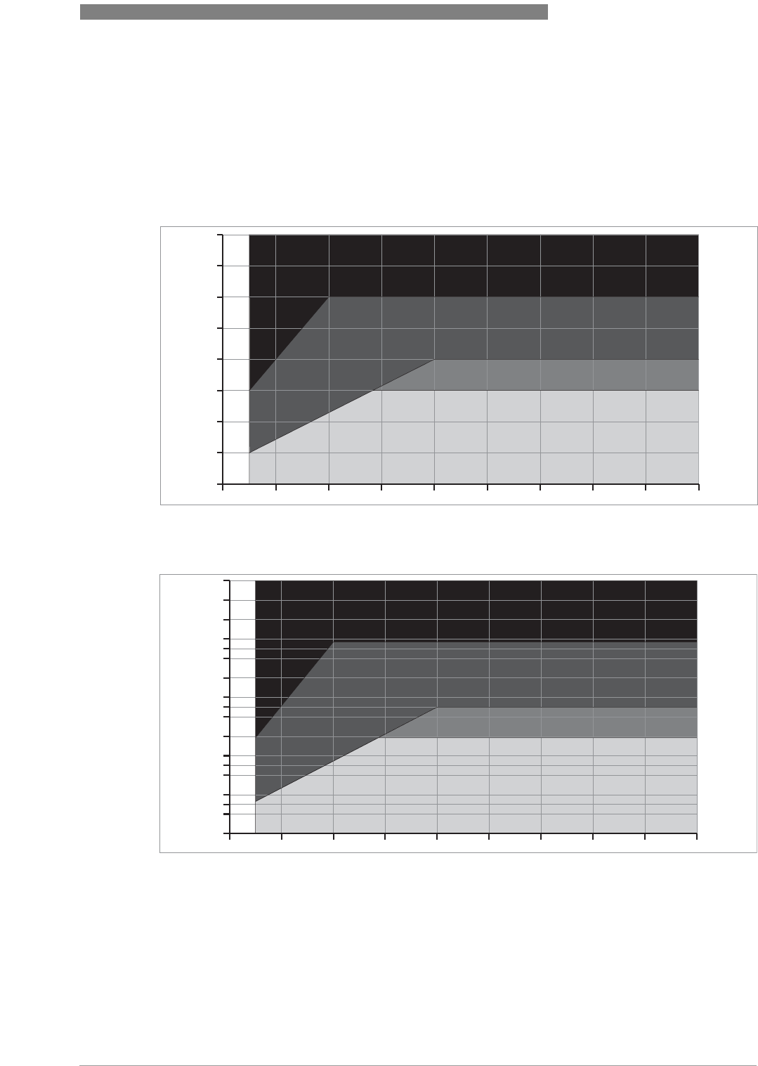
TECHNICAL DATA 8
93
OPTIWAVE 6300 C
www.krohne.com04/2009 - 4000547001 - HB OPTIWAVE 6300 R01 en
8.3 Antenna selection
This graph shows which antenna to select for the application based on:
•D, the measuring range and
•εr, is the dielectric constant of the product being measured
Figure 8-2: Selection of antenna for solid applications (graph of distance in m against εr)
Figure 8-3: Selection of antenna for solid applications (graph of distance in ft. against εr)
1 Distance, D [m]
2 Distance, D [ft]
3 Dielectric constant (εr)
4 On request
5 DN 150 Drop antenna
6 DN 100 horn and DN 150 Drop antenna
7 DN 80 horn, DN 80 Drop, DN 100 horn and DN 150 Drop antenna
1
5
3
7
4
6
12345678910
0
10
20
30
40
50
60
70
80
2
4
3
5
7
6
12345678910+
0
20
30
40
60
70
80
100
120
130
140
160
180
190
200
220
240
260
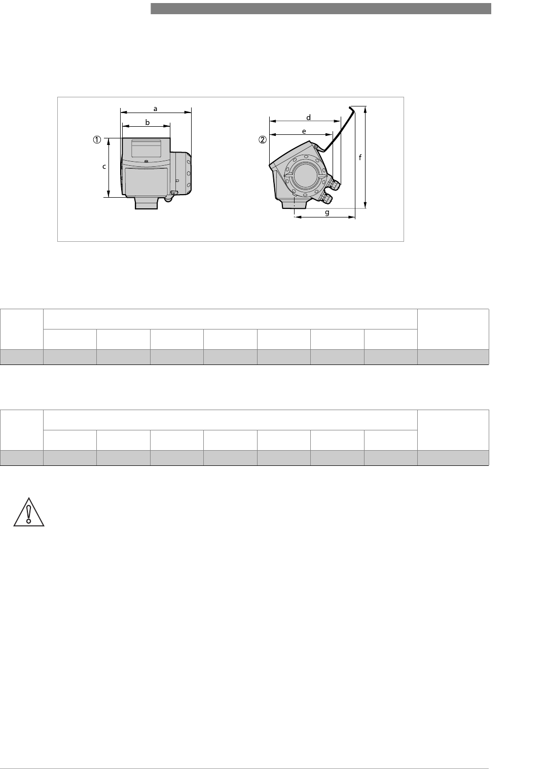
8 TECHNICAL DATA
94
OPTIWAVE 6300 C
www.krohne.com 04/2009 - 4000547001 - HB OPTIWAVE 6300 R01 en
8.4 Dimensions and weights
Dimensions and weights in mm and kg
Dimensions and weights in inches and lbs
Housing
Figure 8-4: Housing dimensions
1 Housing front view
2 Housing side view
Dimensions [mm] Weights [kg]
a b c d e f g
Housing 180 122 158.5 182 1 167 277 155 3.3
1if fitted with standard cable glands
Dimensions [inches] Weights [lbs]
a b c d e f g
Housing 7.1 4.8 6.2 7.2 1 6.5 10.9 6.1 7.3
1if fitted with standard cable glands
CAUTION!
•
Cable glands are delivered on demand with non-Ex, Ex i- and Ex d-approved devices.
•
The diameter of the outer sheath of the cable must be 6
…
12 mm or 0.2
…
0.5
¨
.
•
Cable glands for FM- or CSA-approved devices must be supplied by the customer.
•
A weather protection cover is available on request with all devices.
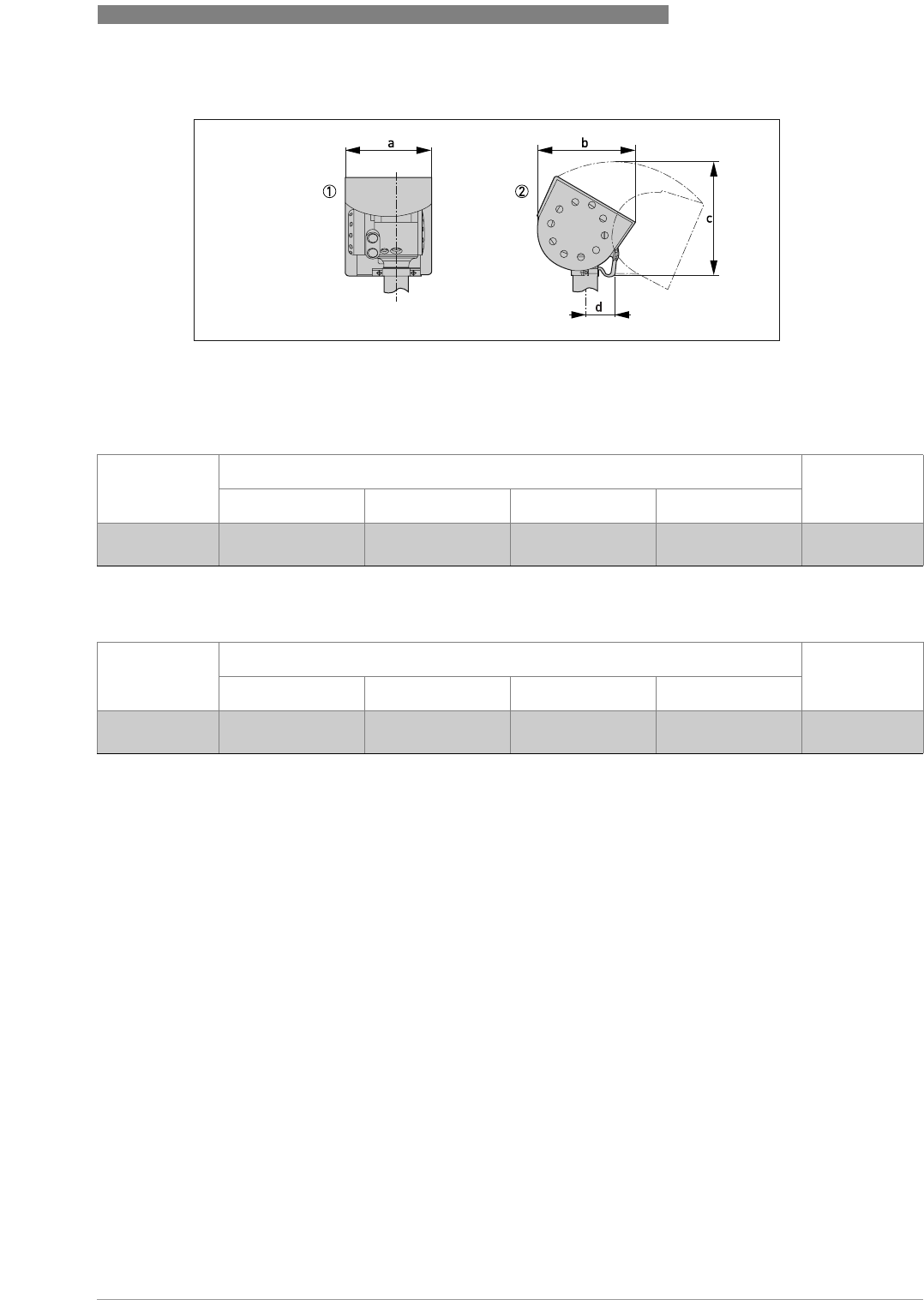
TECHNICAL DATA 8
95
OPTIWAVE 6300 C
www.krohne.com04/2009 - 4000547001 - HB OPTIWAVE 6300 R01 en
Dimensions and weights in mm and kg
Dimensions and weights in inches and lbs
Weather protection
Figure 8-5: Dimensions of the weather protection option
1 Weather protection, back view
2 Weather protection, left side view
Dimensions [mm] Weights [kg]
a b c d
Weather
protection
208 231.5 268 1 66 2.9
1radius
Dimensions [inches] Weights [lbs]
a b c d
Weather
protection
8.2 9.1 10.6 1 2.6 6.4
1radius
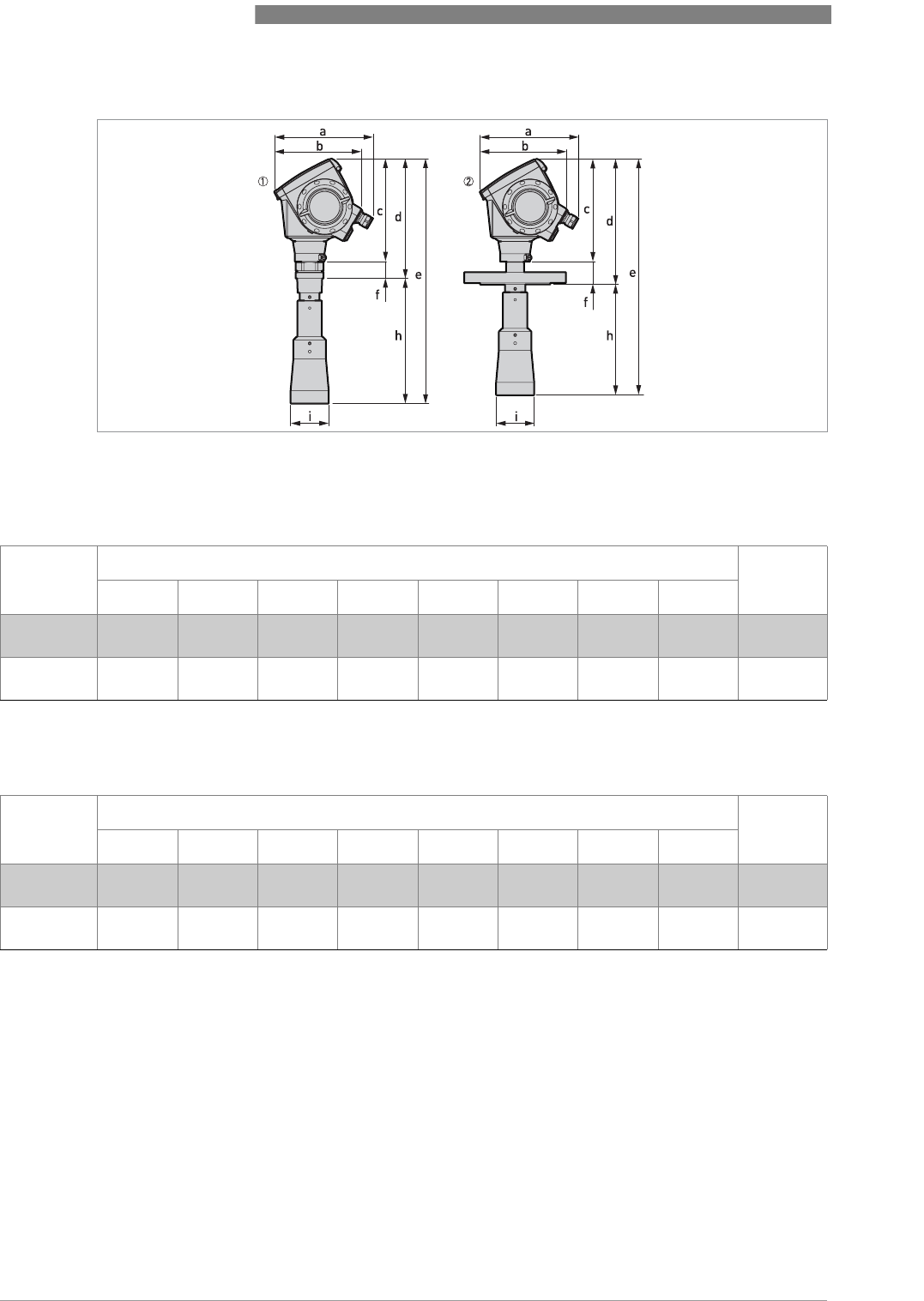
8 TECHNICAL DATA
96
OPTIWAVE 6300 C
www.krohne.com 04/2009 - 4000547001 - HB OPTIWAVE 6300 R01 en
Dimensions and weights in mm and kg
Dimensions and weights in inches and lbs
DN80/3¨ horn antenna versions
Figure 8-6: DN80/3¨ horn antenna versions
1 DN80/3¨ horn antenna with G1½ or 1½NPT thread connection
2 DN80/3¨ horn antenna with flange connection
Dimensions [mm] Weights
[kg]
a b c d e f h Øi
Thread
connection
182 1 167 201 233 479 32 246 2 75 5.5
Flange
connection
182 1 167 201 246 463 45 217 2 75 6.9…26.2
1if fitted with standard cable glands
2additional antenna extensions of Ø39 x length 105 mm are available
Dimensions [inches] Weights
[lbs]
a b c d e f h Øi
Thread
connection
7.2 1 6.5 7.9 9.2 18.9 1.3 9.7 2 312.1
Flange
connection
7.2 1 6.5 7.9 9.7 18.2 1.8 8.5 2 315.2…57.8
1if fitted with standard cable glands
2additional antenna extensions of Ø1.5 x length 4.1¨ are available
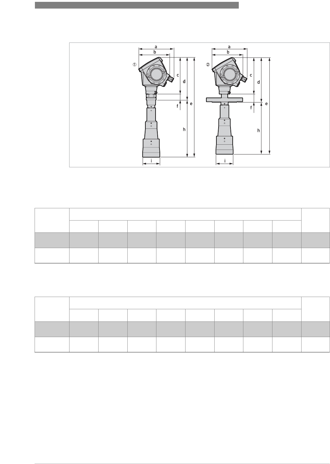
TECHNICAL DATA 8
97
OPTIWAVE 6300 C
www.krohne.com04/2009 - 4000547001 - HB OPTIWAVE 6300 R01 en
Dimensions and weights in mm and kg
Dimensions and weights in inches and lbs
DN100/4¨ horn antenna versions
Figure 8-7: DN100/4¨ horn antenna versions
1 DN100/4¨ horn antenna with G1½ or 1½NPT thread connection
2 DN100/4¨ horn antenna with flange connection
Dimensions [mm] Weights
[kg]
a b c d e f h Øi
Thread
connection
182 1 167 201 233 548 32 315 2 95 6.5
Flange
connection
182 1 167 201 246 532 45 286 2 95 7.9…27.2
1if fitted with standard cable glands
2additional antenna extensions of Ø39 x length 105 mm are available
Dimensions [inches] Weights
[lbs]
a b c d e f h Øi
Thread
connection
7.2 1 6.5 7.9 9.2 21.6 1.3 12.4 2 3.7 14.3
Flange
connection
7.2 1 6.5 7.9 9.7 20.9 1.8 11.3 2 3.7 17.4…60
1if fitted with standard cable glands
2additional antenna extensions of Ø1.5 x length 4.1¨ are available
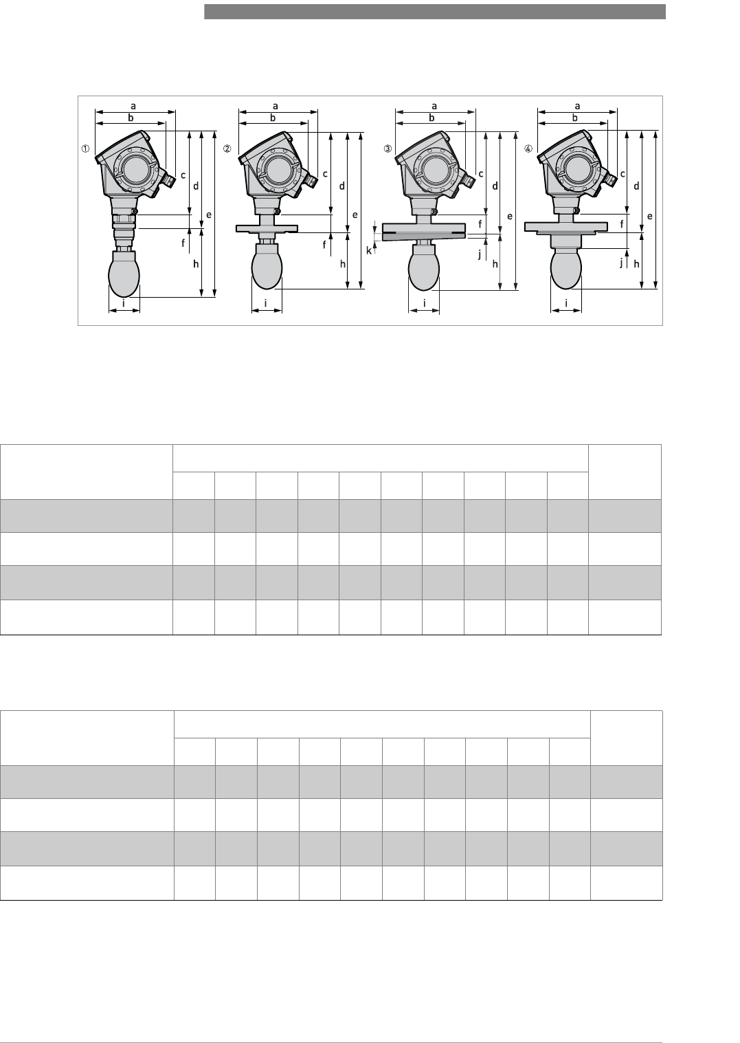
8 TECHNICAL DATA
98
OPTIWAVE 6300 C
www.krohne.com 04/2009 - 4000547001 - HB OPTIWAVE 6300 R01 en
Dimensions and weights in mm and kg
Dimensions and weights in inches and lbs
DN80/3¨ Drop antenna versions
Figure 8-8: DN80/3¨ Drop antenna versions
1 DN80/3¨ Drop antenna with G1½ or 1½NPT thread connection
2 DN80/3¨ Drop antenna with flange connection
3 DN80/3¨ Drop antenna with slanted flange connection (PP material option only)
4 DN80/3¨ Drop antenna, with PP or PTFE flange plate protection option
Dimensions [mm] Weights
[kg]
a b c d e f h Øi j k
Thread connection 182
1
167 201 234 399 33 165
2
74 - - 5.7…6.1
Flange connection 182
1
167 201 246 383 45 137
2
74 - - 6.3…26
Flange connection with
slanted flange option
182
1
167 201 246 383 45 137
2
74 10 2°6.4…26.6
Flange connection with
flange plate protection option
182
1
167 201 246 383 45 137 74 39 -6.6…26.8
1if fitted with standard cable glands
2additional antenna extensions of Ø39 x length 105 mm are available. Do not attach more than 5 antenna extensions.
Dimensions [inches] Weights
[lbs]
a b c d e f h Øi j k
Thread connection 7.2
1
6.5 7.9 9.2 15.7 1.3 6.5
2
2.9 - - 12.6…13.4
Flange connection 7.2
1
6.5 7.9 9.7 15.1 1.8 5.4
2
2.9 - - 13.9…57.3
Flange connection with
slanted flange option
7.2
1
6.5 7.9 9.7 15.1 1.8 5.4
2
2.9 0.4 2°14.1…58.6
Flange connection with
flange plate protection option
7.2
1
6.5 7.9 9.7 15.1 1.8 5.4 2.9 1.5 -13.9…59.1
1if fitted with standard cable glands
2additional antenna extensions of Ø1.5 x length 4.1¨ available. Do not attach more than 5 antenna extensions.
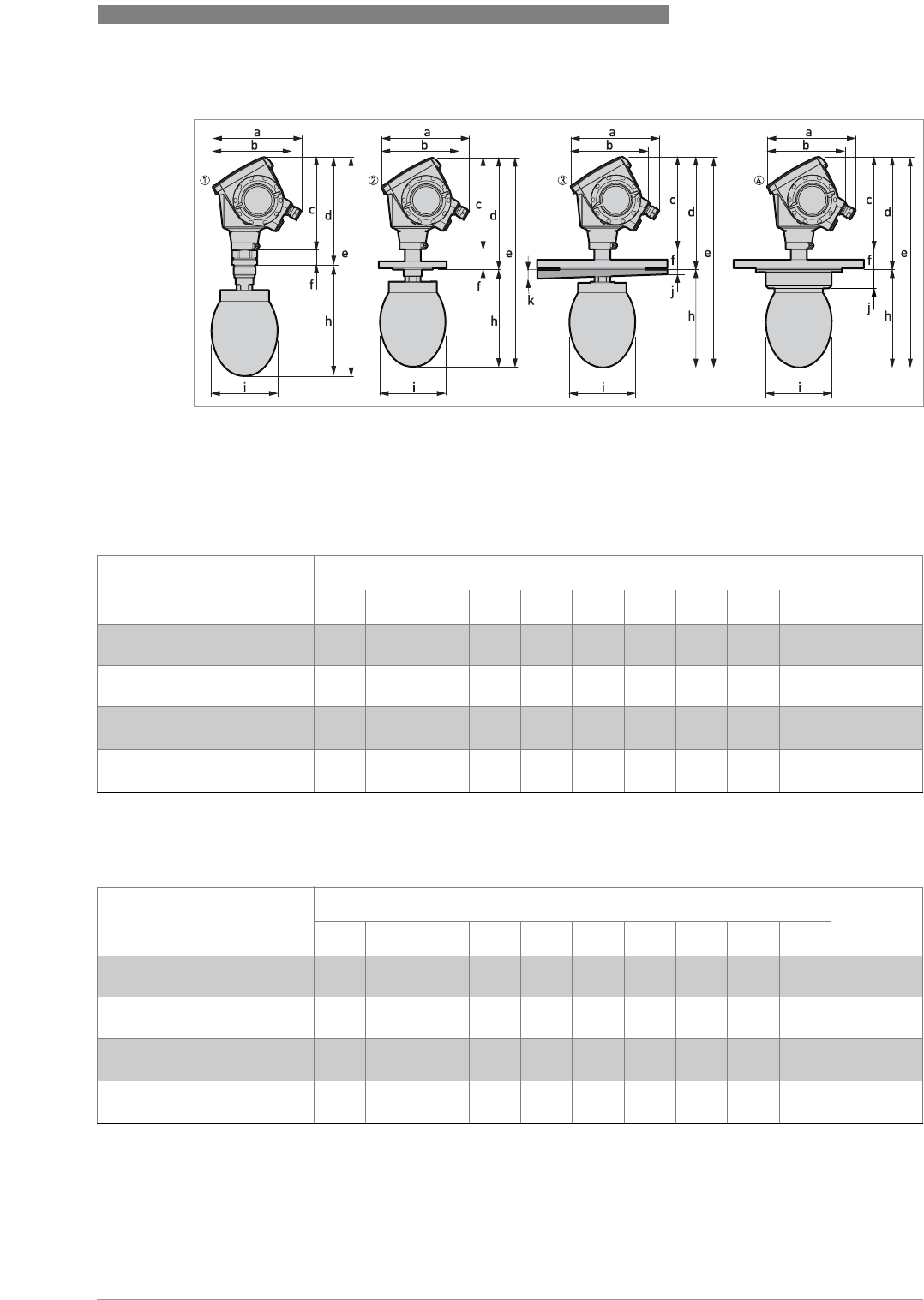
TECHNICAL DATA 8
99
OPTIWAVE 6300 C
www.krohne.com04/2009 - 4000547001 - HB OPTIWAVE 6300 R01 en
Dimensions and weights in mm and kg
Dimensions and weights in inches and lbs
DN150/6¨ Drop antenna versions (PP material option only)
Figure 8-9: DN150/6¨ Drop antenna versions (PP material option only)
1 DN150/6¨ Drop antenna with flange connection
2 DN150/6¨ Drop antenna with thread connection
3 DN150/6¨ Drop antenna with slanted flange connection
4 DN150/6¨ Drop antenna, with flange plate protection option
Dimensions [mm] Weights
[kg]
a b c d e f h Øi j k
Thread connection 182
1
167 201 234 476 33 242
2
144 - - 7.4
Flange connection 182
1
167 201 246 460 45 214
2
144 - - 8…27.3
Flange connection with
slanted flange option
182
1
167 201 246 460 45 214
2
144 10 2°8.1…27.9
Flange connection with
flange plate protection option
182
1
167 201 246 460 45 214 144 39 - -
1if fitted with standard cable glands
2additional antenna extensions of Ø39 x length 105 mm are available. Do not attach more than 5 antenna extensions.
Dimensions [inches] Weights
[lbs]
a b c d e f h Øi j k
Thread connection 7.2
1
6.5 7.9 9.2 18.7 1.3 9.5
2
5.7 - - 16.3
Flange connection 7.2
1
6.5 7.9 9.7 18.1 1.8 8.4
2
5.7 - - 17.6…60.2
Flange connection with
slanted flange option
7.2
1
6.5 7.9 9.7 18.1 1.8 8.4
2
5.7 0.4 2°17.8…61.5
Flange connection with
flange plate protection option
7.2
1
6.5 7.9 9.7 18.1 1.8 8.4 5.7 1.5 - -
1if fitted with standard cable glands
2additional antenna extensions of Ø1.5 x length 4.1¨ are available. Do not attach more than 5 antenna extensions.

9 APPENDIX
100
OPTIWAVE 6300 C
www.krohne.com 04/2009 - 4000547001 - HB OPTIWAVE 6300 R01 en
9.1 Order form
You can help us to assist you as quickly as possible by giving us a few items of information.
Then just fax them to us. Your personal KROHNE consultant will contact you within 24 hours.
9.1.1 Device data
9.1.2 Rating data
9.1.3 Contact data
Connection type Flange Threaded Specify size:
Connection material 316 L Hastelloy® C-22
Feedthrough/Sealing Standard/ FKM/FPM
(-40...+200°C)
Standard/
Kalrez®6375
(-20...+200°C)
Standard/ EPDM
(-40...+150°C)
Metaglas®/ FKM/FPM
(-30...+200°C)
Metaglas®/
Kalrez®6375
(-20...+200°C)
Metaglas®/ EPDM
(-30...+150°C)
Outputs 1 output 4...20 mA/
HART®
2 outputs 4...20 mA
HART® + 4...20 mA
Display Without With Specify language:
Approvals No Ex ATEX II G 1, 1/2, 2
Ex ia IIC T6...T3
ATEX II G 1/2, 2 Ex
d[ia] IIC T6...T3
ATEX II D 1, 1/2, 2
Ex iaD or Ex iaD 20/21
or Ex iaD 21 IP6X
T65°C...T90°C
ATEX II D 1/2, 2
Ex tD[iaD] A21/20 or
Ex tD[iaD] A21 IP6X
T65°C...90°C
Product name:
Operating pressure:
Rated pressure:
Process connection
temperature:
Ambient temperature:
Operating density:
Viscosity:
Measurand (level,
volume,...):
Silo height:
Comments (indoors,
exposed to weather, ...):
Company:
Contact person:
Telephone number:
Fax number:
E-mail:

APPENDIX 9
101
OPTIWAVE 6300 C
www.krohne.com04/2009 - 4000547001 - HB OPTIWAVE 6300 R01 en
9.2 Glossary
D
E
F
H
I
L
Dead zone Non-measurement zone.
Dielectric constant An electrical property of the product to be measured used in Radar
measurement. Also known as εr, DK and relative permittivity. Defines the
strength of the wave reflected back to the device's signal converter.
Distance The distance from the face of flange to the level (1 product) or the surface
of the top product (2 or more products). See the diagrams at the end of this
section.
Drop antenna A new generation of antenna made of PP or PTFE. It has an ellipsoidal
shape for a more precise emission of radar signals.
DTM Device Type Manager. A driver for use in the PACTware™ program. All data
and functions of the device are included in it.
Electromagnetic compatibility Defines how much a device influences or is influenced by other devices that
generate electromagnetic fields during operation. Refer to European
standard EN 61326-1 for further details.
FMCW Frequency-modulated continuous-wave radar technology. The signal is
continuously present, but the frequency is modulated, usually in
successive linear ramps over time (frequency sweeps).
Horn (cone) antenna A common antenna for most applications. It is used for the controlled
emission and collection of radar signals.
Hazardous area An area with a potentially explosive atmosphere. Trained personnel can
install and use a device in this area. The device must be ordered with the
appropriate options. The device requires approvals (ATEX, IEC Ex, FM, CSA,
NEPSI etc.) related to site specifications. You can find more data about
hazardous areas in the Ex Manuals and Ex Certificates of Compliance.
Interference signals False radar reflections.
Level Height from the bottom of the silo (user-defined) to the surface of the top
product (Tank height – distance). See the diagrams at the end of this
section.

9 APPENDIX
102
OPTIWAVE 6300 C
www.krohne.com 04/2009 - 4000547001 - HB OPTIWAVE 6300 R01 en
M
O
P
R
S
T
U
V
W
Mass Total mass of silo contents.
Operators Users who can choose how to display measurements. They cannot
configure the device in supervisor mode.
PACTware™ Software that operates and configures field devices from a remote
workstation. It is not necessary to use fieldbus software or programs
developed by the manufacturer.
Radar reflection Signal reflected from the surface of the silo contents.
Signal converter A set of electronic components in the device that send the reflected
measurement pulse through some signal filters. They identify and
measure the level of the silo contents.
Supervisor Users who can configure the device in supervisor mode. They cannot
configure the device in service mode.
TBF Tank Bottom Following (TBF) mode is an alternative measurement mode. It
allows the device to measure silo contents with low dielectric constants.
TBF mode uses the reflection of the silo bottom to indirectly measure the
level of the silo contents.
Ullage volume Unfilled volume. See the diagrams at the end of this section.
Volume Total volume of silo contents.
Waveguide A PTFE component that is used to guide the emitted radar waves correctly
into the horn antenna.
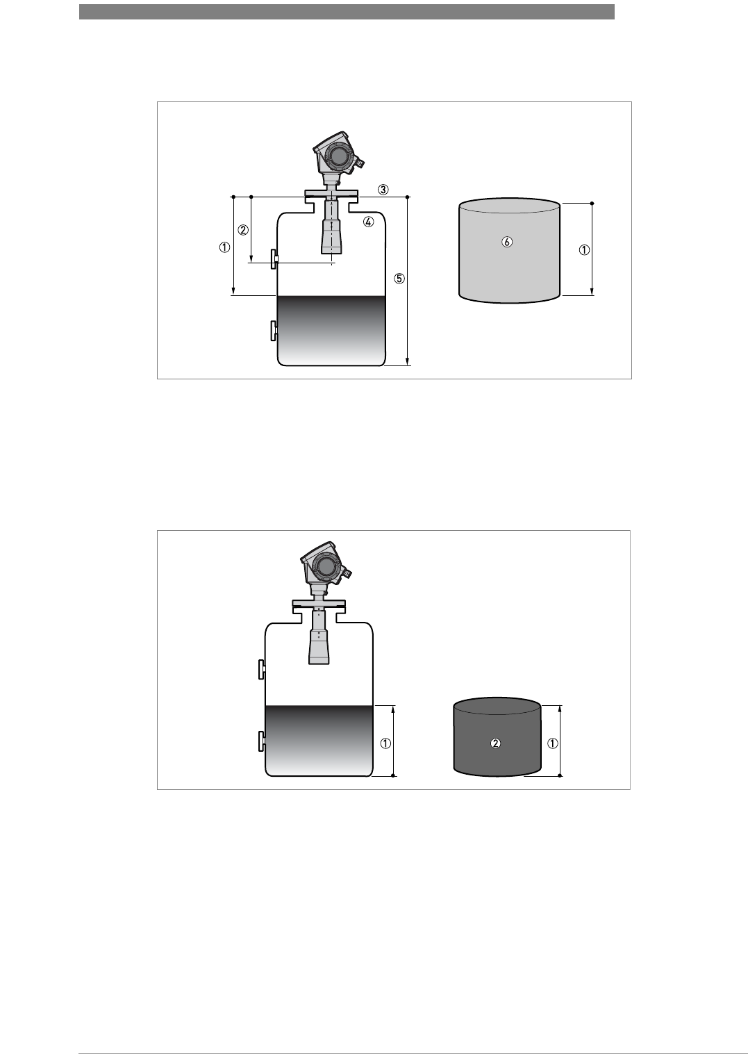
APPENDIX 9
103
OPTIWAVE 6300 C
www.krohne.com04/2009 - 4000547001 - HB OPTIWAVE 6300 R01 en
Figure 9-1: Measurement definitions: distance
1 Distance
2 Dead zone
3 Flange facing
4 Gas (Air)
5 Tank height
6 Ullage volume or mass
Figure 9-2: Measurement definitions: level
1 Level
2 Volume or mass

KROHNE product overview
•Electromagnetic flowmeters
•Variable area flowmeters
•Ultrasonic flowmeters
•Mass flowmeters
•Vortex flowmeters
•Flow controllers
•Level meters
•Temperature meters
•Pressure meters
•Analysis products
•Measuring systems for the oil and gas industry
•Measuring systems for sea-going tankers
Head Office KROHNE Messtechnik GmbH & Co. KG
Ludwig-Krohne-Str. 5
D-47058 Duisburg (Germany)
Tel.:+49 (0)203 301 0
Fax:+49 (0)203 301 10389
info@krohne.de
© KROHNE 04/2009 - 4000547001 - HB OPTIWAVE 6300 R01 en - Subject to change without notice.
The current list of all KROHNE contacts and addresses can be found at:
www.krohne.com