KTV Global LT104AA1 10.4" LCD TV Receiver User Manual
KTV Global Corporation 10.4" LCD TV Receiver
UserManual.wiki
>
KTV Global
>
LT104AA1 User Manual
User Manual
Navigation menu
Upload a User Manual
Namespaces
Wiki Guide
HTML
PDF
Info
Views
User Manual
Discussion / Help
Navigation

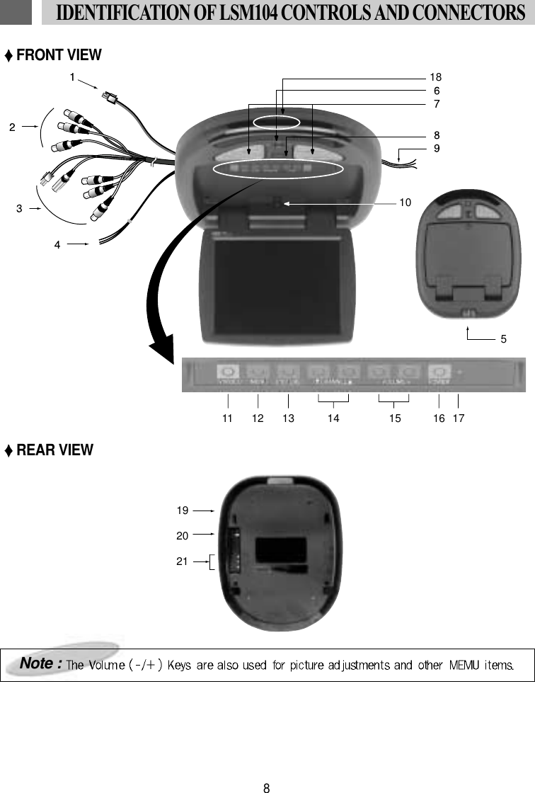
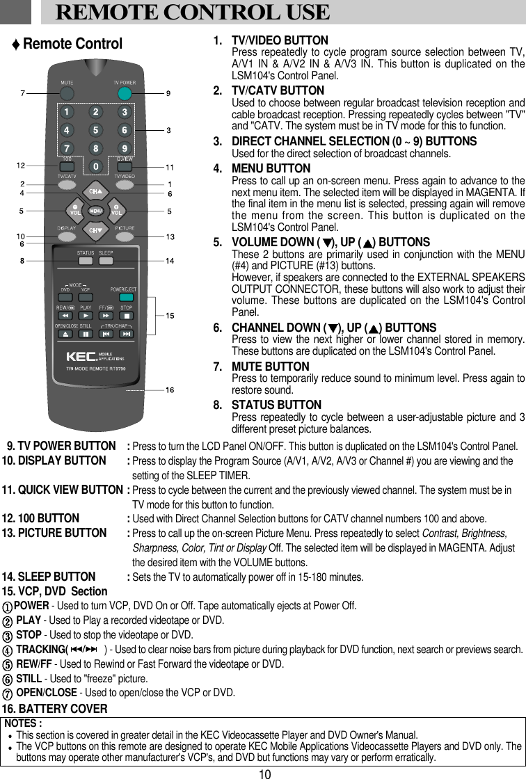
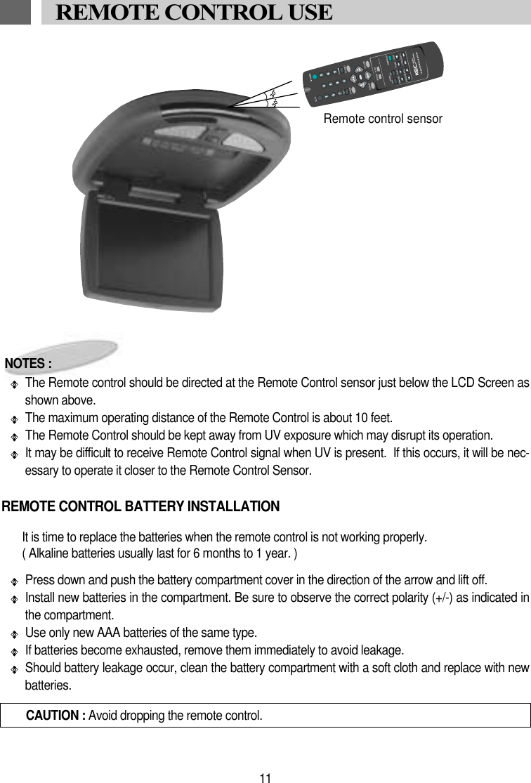
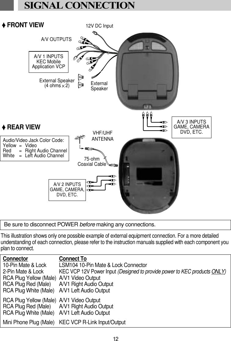
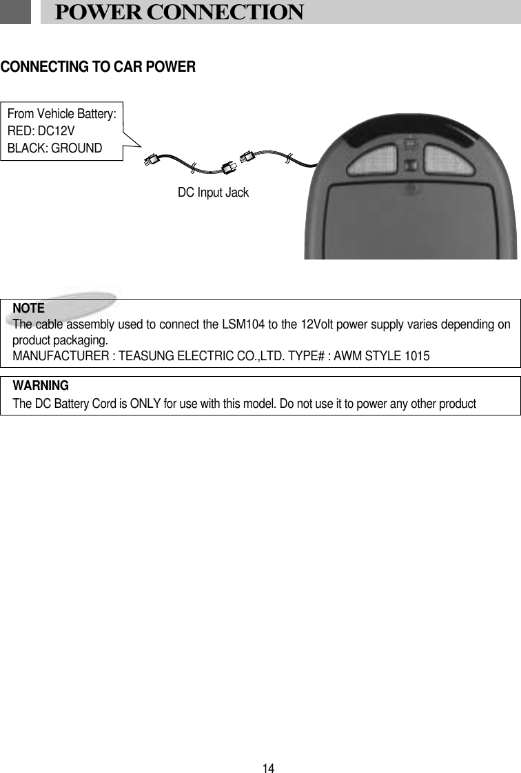
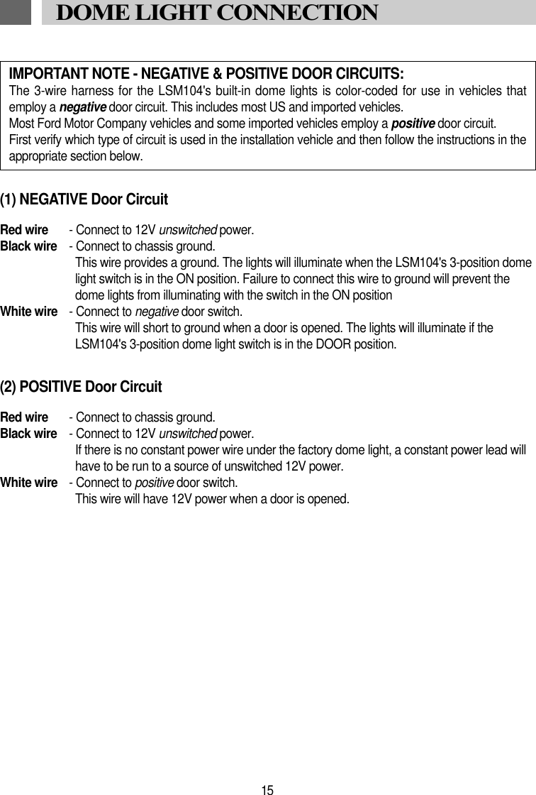
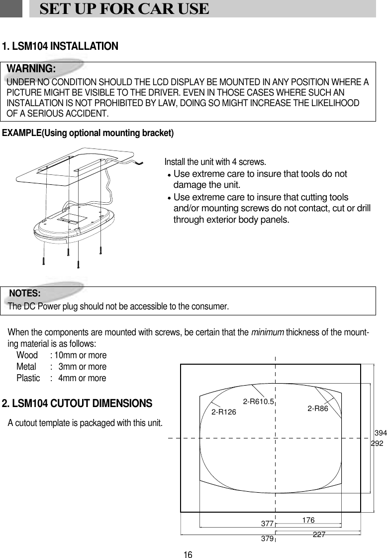
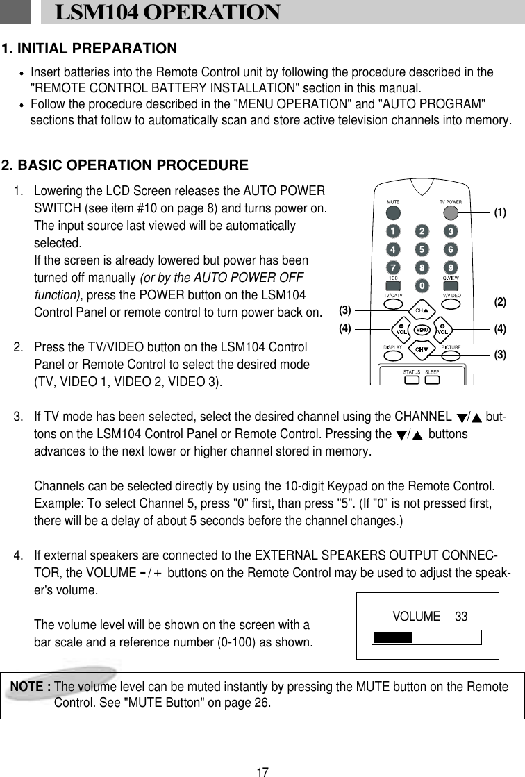
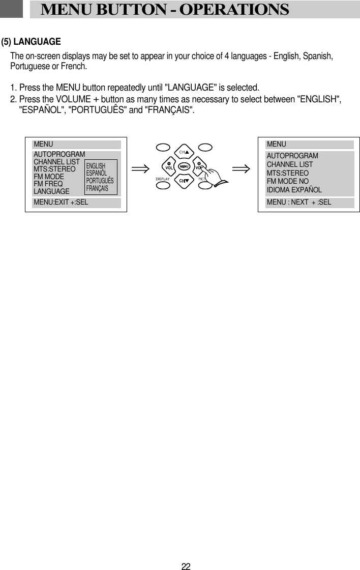
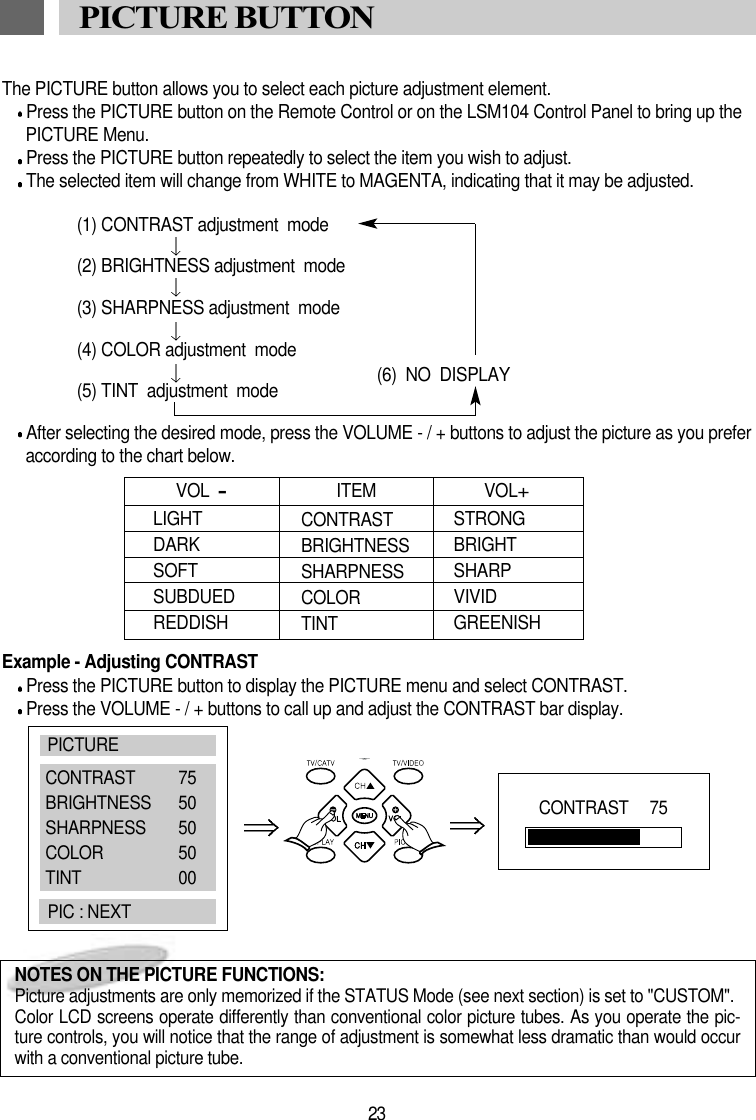
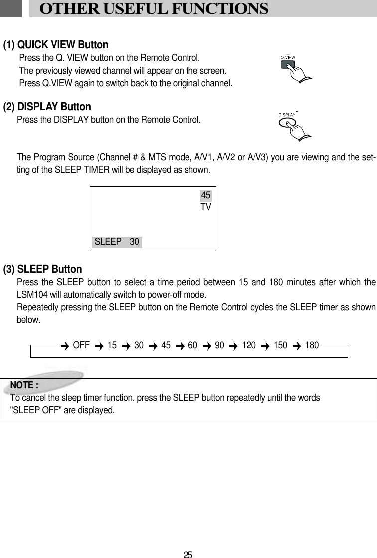
![1. DC INPUT JACKFor connection to source of 12 Volt DC power.2. L&R AUDIO/VIDEO (THROUGH) OUTPUTJACKSSupplies L&R Audio and Video signal for connec-tion to additional monitors, external amplifiers,etc.When the screen is lowered, these outputsalways feed the signal from the selected inputsource.When the screen is in the closed position, theseoutputs always feed the signal from the programsource connected to A/V1.3. L&R AUDIO/VIDEO 1 INPUT JACKSFor connection of a 1st external program source.DC OUT JACKFor connection to a supplies of 12 volt DC power.R-Link JACKFor connection to an external KEC MobileApplications VCP or DVD Player.4. EXTERNAL SPEAKERS OUTPUT CON-NECTORSupplies 2.0 W/Channel @ 4 (variable) for con-nection of optional external speakers. Use withsupplied External Speaker Extension Cable(L&R+ & Common Ground).5. AV3 INPUT JACKFor connection of a 3rd program source.6. LAMPS SWITCHSelects lighting mode.7. LAMPSProvides additional vehicle lighting.8. LCD PANEL DROP-DOWN BUTTONPush to release LCD Panel from stored position.9. LAMP POWER INPUT WIRES12V Constant, Chassis Ground & Door Switch.10. AUTO POWER SWITCHLowering LCD Panel automatically turns poweron.11. TV/VIDEO BUTTONSelects program source: Broadcast TV, A/V1,A/V2, A/V3.12. MENU BUTTONDisplays on-screen Main menu.13. PICTURE BUTTONDisplays on-screen Picture menu14. CHANNEL DOWN ( ), UP ( ) BUTTONSSelects the next lower or higher channel stored inmemory.15. VOLUME DOWN ( ), UP ( ) BUTTONSAdjusts volume of [optional] speakers wired toExternal Speakers Output Connector (#2). Also used in conjunction with the on-screenmenus.16. POWER BUTTONPress to power the LCD Panel ON/OFF.17. STAND-BY INDICATORIlluminates to indicate that 12 Volt DC Power isavailable, but that LCD screen is not powered on.18. REMOTE CONTROL SENSORReceives control signals from the remote controlhand unit. Also passes controls signals to a KECMobile Applications Videocassette Player that isconnected via an R-Link cable.19. FM TRANSMITTER ANTENNATransmits low-power stereo audio signal forreception on vehicle's FM Radio. 20. ANTENNA INPUT JACKFor connection of an external television broad-cast antenna.21. L&R AUDIO/VIDEO 2 INPUT JACKSFor connection of a 2nd program source.9](https://usermanual.wiki/KTV-Global/LT104AA1/User-Guide-769393-Page-10.png)