KTV Global LT104AA1 10.4" LCD TV Receiver User Manual
KTV Global Corporation 10.4" LCD TV Receiver
User Manual

THIS PRODUCT HAS BEEN DESIGNED, MANUFACTURED AND
INSPECTED IN COMPLIANCE WITH THE
ISO9001 QUALITY ASSURANCE SYSTEM.
Part No. 11907073
10.4"TFT LCD TELEVISION MONITOR/RECEIVER SYSTEM
INSTALLATION INFORMATION
& OPERATING INSTRUCTIONS
THIS PRODUCT IS INTENDED FOR PROFESSIONAL INSTALLATION ONLY
FOR MOBILE-SPECIFIC 12 VOLT DC-ONLY OPERATION
PLEASE READ ALL OPERATING INSTRUCTIONS BEFORE USING THIS PRODUCT.
IMPORTANT NOTE :
WHEN USED IN A VEHICLE, THIS SYSTEM IS INTENDED PRIMARILY AS A MONITOR FOR A VIDEO
CASSETTE PLAYER, VIDEO GAME, OR CAMERA.
TELEVISION BROADCAST RECEPTION WILL BE ADVERSELY AFFECTED BY CONDITIONS SUCH AS
MOTION, CHANGE OF DIRECTION, ATMOSPHERIC ACTIVITY, AND LOCAL SURROUNDINGS.
IT IS THEREFORE LIKELY THAT BROADCAST PICTURE QUALITY WILL BE MARGINAL WHEN THIS
SYSTEM IS USED IN A MOBILE ENVIRONMENT.
MOBILE
APPLICATIONS
MODEL: LSM-104
FCC WARNINGS :
This equipment may generate or use radio frequency energy. Change or modifications to this equip-
ment may cause harmful interference unless the modifications are expressly approved in the instruc-
tion manual.
The user could lose the authorization to operate this equipment if an unauthorized change or modifi-
cation is made.
CAUTION
RISK OF ELECTRIC SHOCK
DO NOT OPEN
DO NOT OPEN ELECTRIC SHOCK.
DO NOT REMOVE COVER (OR BACK)
NO USER-SERVICEABLE
PARTS INSIDE.
REFER SERVICING TO
QUALIFIED SERVICE PERSONNEL
CAUTION :
ANY CHANGES OR MODIFICATIONS IN CONSTRUCTION OF THIS DEVICE WHICH ARE NOT
EXPRESSLY APPROVED BY THE PARTY RESPONSIBLE FOR COMPLIANCE COULD VOID THE
USER'S AUTHORITY TO OPERATE THE EQUIPMENT.
WARNINGS :
TO PREVENT FIRE OR SHOCK HAZARD, DO NOT EXPOSE THIS UNIT TO RAIN OR MOISTURE.
DO NOT OPEN THE CABINET. DANGEROUS HIGH VOLTAGE IS PRESENT. SERVICING SHOULD
ONLY BE PERFORMED BY QUALIFIED PERSONNEL.
THIS LCD VIDEO SYSTEM SHOULD ONLY BE OPERATED WITH 12V DC.
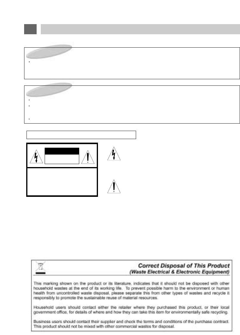
GRAPHICAL SYMBOLS EXPLANATION
This lightning flash with arrowhead symbol,
within an equilateral triangle is intended to alert the user
to the presence of uninsulated "dangerous voltage" within
the product's enclosure that may be of sufficient magni-
tude to constitute a risk of electric shock to persons.
The exclamation point within an equilateral triangle is
intended to alert the user to the presence of important
operating and maintenance (Servicing) instructions in the
literature accompanying the appliance.
2
CAUTIONS

1. Read Instructions-All the safety and operating instructions should be read before the appliance
is operated.
2. Retain Instructions-The safety and operating instructions should be retained for future refer-
ence.
3. Heed Warnings-All warnings on the product and in the operating instructions should be adhered
to.
4. Follow Instructions-All operating and use instructions should be followed.
5. Cleaning-Unplug this product from power cable connector before cleaning. Do not use liquid
cleaners or aerosol cleaners. Use a damp cloth for cleaning.
6. Attachments-Do not use attachments not recommended by the product manufacturer as they
may cause hazards.
7. Water and Moisture-Do not install this product near water-for example, near a bath tub, wash-
bowl, kitchen sink, or laundry tub; in a wet basement; or near a swimming pool; and the like.
8. Accessories-Do not place this product on an unstable cart, stand, tripod, bracket, or table. The
product may fall, causing serious injury to a child or adult, and serious damage to the equipment.
Use only with a cart, stand, tripod, bracket, or table recommended by the manufacturer, or sold
with the product. Any mounting of the product should follow the manufacturer’s instructions, and
should use a mounting approved by the manufacturer.
9. A product and cart combination should be moved with care.
Quick stops, excessive force, and uneven surfaces may cause the product and cart combination
to overturn.
10. Ventilation-Slots and openings in the cabinet are
provided for ventilation and to ensure reliable operation of the product and to
protect it from overheating, and these should never be blocked by placing
the product on a bed, sofa, rug, or other similar surface.
This product should not be placed in a built-in installation such as a
bookcase or rack unless proper ventilation such as a bookcase or rack
unless proper ventilation is provided or the manufacturer's instructions have been adhered to.
11. Power Sources-This product should be operated only from the type of power source indicated on
the marking label. lf you are not sure of the type of power supply to your car, consult your product
dealer.
For products intended to operate from battery power, or other source, refer to the operating
instructions.
12. Servicing-Do not attempt to service this product yourself as opening or removing covers may
expose you to dangerous voltage or other hazards. Refer all servicing to qualified service person-
nel.
3
IMPORTANT SAFEGUARDS

13. Damage requiring Service-Unplug this product the wall outlet and refer servicing to qualified
service personnel under the following conditions :
a. When the power-supply cord or plug is damaged.
b. lf liquid has been supplied, or objects have fallen into the product.
c. lf the product has been exposed to rain or water.
d. If the product does not operate normally by following the operating instructions. Adjust only
those controls that are covered by the operating instructions as an improper adjustment of
other controls may result in damage and will often require extensive work by a qualified techni-
cian to restore the product to its normal operation.
e. lf the product has been dropped, or the cabinet has been damaged.
f. When the product exhibits a distinct change in performance-this indicates a need for service.
14. Replacement Parts-When replacement parts are required, be sure the service technician has
used replacement parts specified by the manufacturer or that have the same characteristics as
the original part.Unauthorized substitutions may result in fire, electric shock or other hazards.
15. Safety Check-Upon completion of any service or repairs to this video product, ask the service
technician to perform safety checks to determine that the video product is in proper operating
condition.
16. Wall or Ceiling Mounting-The product should be mounted to a wall or ceiling only safety rec-
ommended by the manufacturer.
17. Heat-The product should be situated away from heat sources such as radiators, heat registers,
stoves, or other products (including amplifiers) that produce heat.
4
IMPORTANT SAFEGUARDS

We urge you to carefully read all of the descriptions and operating procedures contained in this
Owner's Manual before operating your new LSM104.
CAUTIONS 2
IMPORTANT SAFEGUARDS 3
TABLE OF CONTENTS (THIS PAGE) 5
FEATURES 6
ACCESSORIES 7
IDENTIFICATION OF LSM104 CONTROLS & CONNECTORS 8
REMOTE CONTROL USE 10
SIGNAL CONNECTION 12
POWER CONNECTION 14
DOME LIGHT CONNECTION 15
SET UP FOR CAR USE 16
LSM104 OPERATION 17
MENU BUTTON - GENERAL INFORMATION 18
MENU BUTTON - OPERATIONS 19
PICTURE BUTTON 23
STATUS BUTTON 24
OTHER USEFUL FUNCTIONS 25
RECEPTION DISTURBANCE 27
TROUBLESHOOTING GUIDE 28
SPECIFICATIONS 29
5
TABLE OF CONTENTS

10.4 INCH TFT LCD Panel
12 Volt DC Operation
Wireless Remote Control
MTS Stereo Frequency Synthesizer Tuning System
Full On-Screen Display of all Switching Functions
Full On-Screen Display of all Picture Functions
Automatic Power On, Automatic Power Off & Memory Power On Functions
High Voltage Protection (Over 18 Volts DC)
Polarity Reversal Protection
Four Input Selections (Built-in MTS Stereo TV Tuner, Stereo Audio/Video Inputs 1, 2, & 3)
Low Level Stereo Audio/Video Output
Powered Stereo External Speakers Output
Built-In Stereo FM Transmitter with On-Screen Frequency Selection & Control
Built-In Stereo IR Transmitter
External Antenna Input
10-Year Memory Back Up
The Remote Controller that is packaged with this unit will also control any KEC Mobile Applications
Videocassette or DVD Player.
NOTES:
Automatic Power On Function:
This system will automatically power on whenever the LCD screen is lowered to its viewing position.
Automatic Power Off Function:
This system will automatically turn off approximately 15 minutes after it last receives a video signal.
Memory Power On Function:
If this system was in power on mode when power was last removed (unplugged or ignition off),
it will automatically turn on when power is reapplied.
6
FEATURES
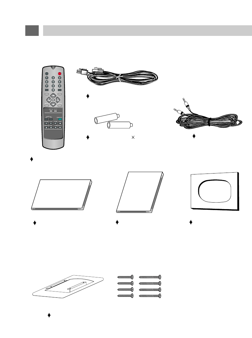
Please check to make sure that all of these items have been included:
REMOTE CONTROL
BATTERIES (AAA 2)
WARRANTY CARD OWNERS MANUAL
ACCESSORIES
HOUSING FRAME & INSTALLATION SCREWS
7
CUTOUT TEMPLATE
Other general and vehicle specific mounting and installation accessories are also available.
The following optional accessory is available from KEC Mobile Applications and/or its distributors at
additional cost:
12V DC Power extension cable
R-Link Cable
19
20
21
5
10
11 12 13 14 15 16 17
18
8
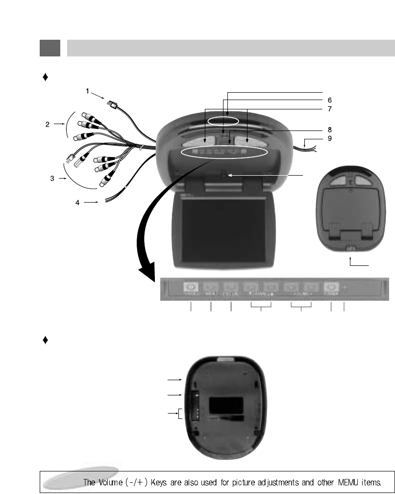
IDENTIFICATION OF LSM104 CONTROLS AND CONNECTORS
Note :
FRONT VIEW
REAR VIEW

1. DC INPUT JACK
For connection to source of 12 Volt DC power.
2. L&R AUDIO/VIDEO (THROUGH) OUTPUT
JACKS
Supplies L&R Audio and Video signal for connec-
tion to additional monitors, external amplifiers,
etc.
When the screen is lowered, these outputs
always feed the signal from the selected input
source.
When the screen is in the closed position, these
outputs always feed the signal from the program
source connected to A/V1.
3. L&R AUDIO/VIDEO 1 INPUT JACKS
For connection of a 1st external program source.
DC OUT JACK
For connection to a supplies of 12 volt DC power.
R-Link JACK
For connection to an external KEC Mobile
Applications VCP or DVD Player.
4. EXTERNAL SPEAKERS OUTPUT CON-
NECTOR
Supplies 2.0 W/Channel @ 4 (variable) for con-
nection of optional external speakers. Use with
supplied External Speaker Extension Cable
(L&R+ & Common Ground).
5. AV3 INPUT JACK
For connection of a 3rd program source.
6. LAMPS SWITCH
Selects lighting mode.
7. LAMPS
Provides additional vehicle lighting.
8. LCD PANEL DROP-DOWN BUTTON
Push to release LCD Panel from stored position.
9. LAMP POWER INPUT WIRES
12V Constant, Chassis Ground & Door Switch.
10. AUTO POWER SWITCH
Lowering LCD Panel automatically turns power
on.
11. TV/VIDEO BUTTON
Selects program source: Broadcast TV, A/V1,
A/V2, A/V3.
12. MENU BUTTON
Displays on-screen Main menu.
13. PICTURE BUTTON
Displays on-screen Picture menu
14. CHANNEL DOWN ( ), UP ( ) BUTTONS
Selects the next lower or higher channel stored in
memory.
15. VOLUME DOWN ( ), UP ( ) BUTTONS
Adjusts volume of [optional] speakers wired to
External Speakers Output Connector (#2).
Also used in conjunction with the on-screen
menus.
16. POWER BUTTON
Press to power the LCD Panel ON/OFF.
17. STAND-BY INDICATOR
Illuminates to indicate that 12 Volt DC Power is
available, but that LCD screen is not powered on.
18. REMOTE CONTROL SENSOR
Receives control signals from the remote control
hand unit. Also passes controls signals to a KEC
Mobile Applications Videocassette Player that is
connected via an R-Link cable.
19. FM TRANSMITTER ANTENNA
Transmits low-power stereo audio signal for
reception on vehicle's FM Radio.
20. ANTENNA INPUT JACK
For connection of an external television broad-
cast antenna.
21. L&R AUDIO/VIDEO 2 INPUT JACKS
For connection of a 2nd program source.
9
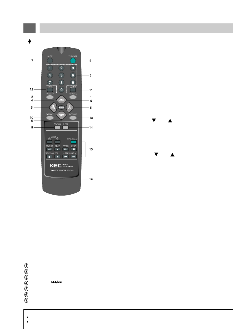
1. TV/VIDEO BUTTON
Press repeatedly to cycle program source selection between TV,
A/V1 IN & A/V2 IN & A/V3 IN. This button is duplicated on the
LSM104's Control Panel.
2. TV/CATV BUTTON
Used to choose between regular broadcast television reception and
cable broadcast reception. Pressing repeatedly cycles between "TV"
and "CATV. The system must be in TV mode for this to function.
3. DIRECT CHANNEL SELECTION (0 ~ 9) BUTTONS
Used for the direct selection of broadcast channels.
4. MENU BUTTON
Press to call up an on-screen menu. Press again to advance to the
next menu item. The selected item will be displayed in MAGENTA. If
the final item in the menu list is selected, pressing again will remove
the menu from the screen. This button is duplicated on the
LSM104's Control Panel.
5. VOLUME DOWN ( ), UP ( ) BUTTONS
These 2 buttons are primarily used in conjunction with the MENU
(#4) and PICTURE (#13) buttons.
However, if speakers are connected to the EXTERNAL SPEAKERS
OUTPUT CONNECTOR, these buttons will also work to adjust their
volume. These buttons are duplicated on the LSM104's Control
Panel.
6. CHANNEL DOWN ( ), UP ( ) BUTTONS
Press to view the next higher or lower channel stored in memory.
These buttons are duplicated on the LSM104's Control Panel.
7. MUTE BUTTON
Press to temporarily reduce sound to minimum level. Press again to
restore sound.
8. STATUS BUTTON
Press repeatedly to cycle between a user-adjustable picture and 3
different preset picture balances.
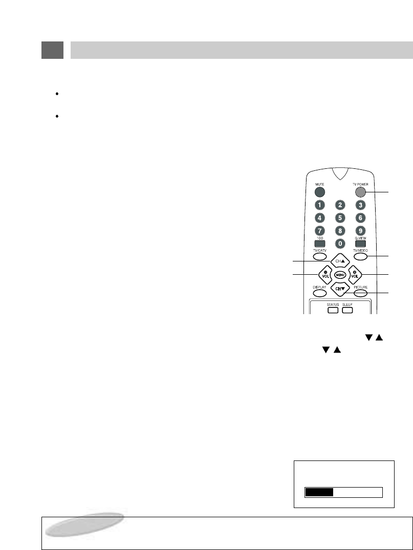
Remote Control
10
REMOTE CONTROL USE
9. TV POWER BUTTON :
Press to turn the LCD Panel ON/OFF. This button is duplicated on the LSM104's Control Panel.
10. DISPLAY BUTTON :
Press to display the Program Source (A/V1, A/V2, A/V3 or Channel #) you are viewing and the
setting of the SLEEP TIMER.
11. QUICK VIEW BUTTON :
Press to cycle between the current and the previously viewed channel. The system must be in
TV mode for this button to function.
12. 100 BUTTON :
Used with Direct Channel Selection buttons for CATV channel numbers 100 and above.
13. PICTURE BUTTON :
Press to call up the on-screen Picture Menu. Press repeatedly to select Contrast, Brightness,
Sharpness, Color, Tint or Display Off. The selected item will be displayed in MAGENTA. Adjust
the desired item with the VOLUME buttons.
14. SLEEP BUTTON :
Sets the TV to automatically power off in 15-180 minutes.
15. VCP, DVD Section
POWER - Used to turn VCP, DVD On or Off. Tape automatically ejects at Power Off.
PLAY - Used to Play a recorded videotape or DVD.
STOP - Used to stop the videotape or DVD.
TRACKING( ) - Used to clear noise bars from picture during playback for DVD function, next search or previews search.
REW/FF - Used to Rewind or Fast Forward the videotape or DVD.
STILL - Used to "freeze" picture.
OPEN/CLOSE - Used to open/close the VCP or DVD.
16. BATTERY COVER
NOTES :
This section is covered in greater detail in the KEC Videocassette Player and DVD Owner's Manual.
The VCP buttons on this remote are designed to operate KEC Mobile Applications Videocassette Players and DVD only. The
buttons may operate other manufacturer's VCP's, and DVD but functions may vary or perform erratically.
11
REMOTE CONTROL USE
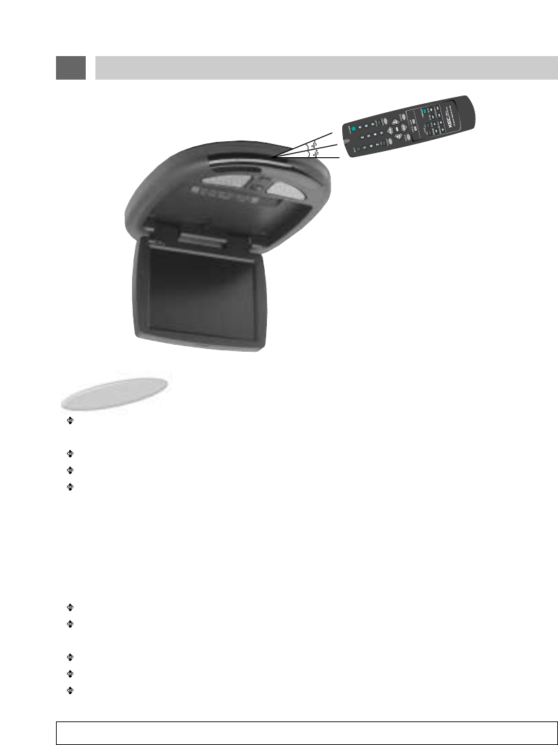
CAUTION : Avoid dropping the remote control.
NOTES :
The Remote control should be directed at the Remote Control sensor just below the LCD Screen as
shown above.
The maximum operating distance of the Remote Control is about 10 feet.
The Remote Control should be kept away from UV exposure which may disrupt its operation.
It may be difficult to receive Remote Control signal when UV is present. If this occurs, it will be nec-
essary to operate it closer to the Remote Control Sensor.
It is time to replace the batteries when the remote control is not working properly.
( Alkaline batteries usually last for 6 months to 1 year. )
Press down and push the battery compartment cover in the direction of the arrow and lift off.
Install new batteries in the compartment. Be sure to observe the correct polarity (+/-) as indicated in
the compartment.
Use only new AAA batteries of the same type.
If batteries become exhausted, remove them immediately to avoid leakage.
Should battery leakage occur, clean the battery compartment with a soft cloth and replace with new
batteries.
REMOTE CONTROL BATTERY INSTALLATION
Remote control sensor
12
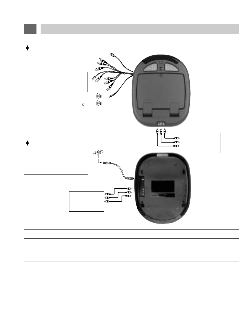
SIGNAL CONNECTION
This illustration shows only one possible example of external equipment connection. For a more detailed
understanding of each connection, please refer to the instruction manuals supplied with each component you
plan to connect.
Be sure to disconnect POWER before making any connections.
Connector Connect To
10-Pin Mate & Lock LSM104 10-Pin Mate & Lock Connector
2-Pin Mate & Lock
KEC VCP 12V Power Input (Designed to provide power to KEC products ONLY)
RCA Plug Yellow (Male) A/V1 Video Output
RCA Plug Red (Male) A/V1 Right Audio Output
RCA Plug White (Male) A/V1 Left Audio Output
RCA Plug Yellow (Male) A/V1 Video Output
RCA Plug Red (Male) A/V1 Right Audio Output
RCA Plug White (Male) A/V1 Left Audio Output
Mini Phone Plug (Male) KEC VCP R-Link Input/Output
External Speaker
(4 ohms 2) External
Speaker
A/V 2 INPUTS
GAME, CAMERA,
DVD, ETC.
A/V 1 INPUTS
KEC Mobile
Application VCP
A/V 3 INPUTS
GAME, CAMERA
DVD, ETC.
A/V OUTPUTS
Audio/Video Jack Color Code:
Yellow = Video
Red = Right Audio Channel
White = Left Audio Channel
FRONT VIEW
REAR VIEW
VHF/UHF
ANTENNA
75-ohm
Coaxial Cable
12V DC Input
AUDIO SYSTEM
The Audio Outputs always feed a low-level audio signal from the selected input.
The Audio Outputs feed a Monophonic signal whenever the selected input source has a Monophonic
audio signal (e.g. a monophonic broadcast from the built-in TV Tuner, or the signal from a Monophonic
VCP connected to the A/V 1, 2 or 3 input terminals).
The Audio Outputs feed a Stereo signal whenever the selected input source has a Stereo audio signal
(e.g. a stereo broadcast received by the built-in TV Tuner, or the signal from a Hi-fi Stereo VCP or DVD
that is connected to the A/V 1, 2 or 3 input terminals).
The EXTERNAL SPEAKERS OUTPUT CONECTOR feeds a high level mono or stereo signal whose
level is Variable up to 2.0W maximum when connected to 4-ohm speakers.
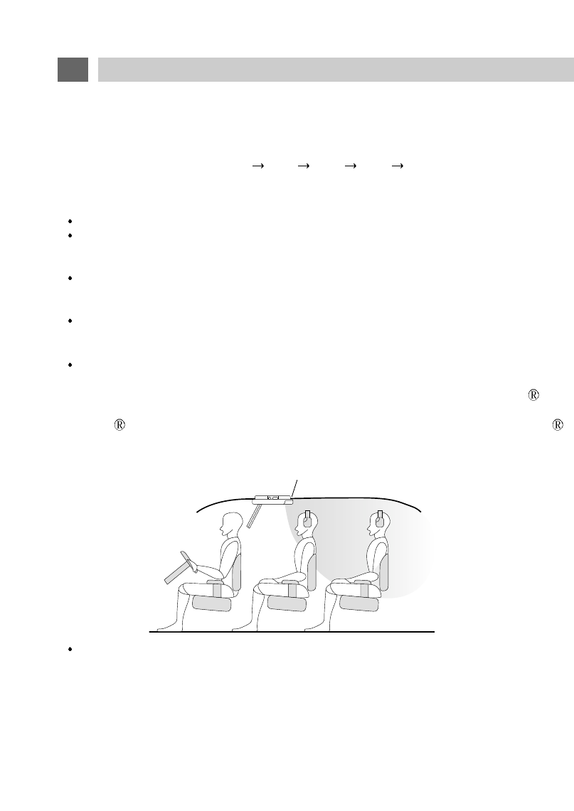
IR (Infrared Rays) Transmitter
The built-in IR Transmitter allows you to listen to the Stereo or Monophonic audio signal from the selected
program source (TV, A/V1, A/V2 or A/V3) on IR Wireless Headphones manufactured by Unwired
Technology LLC. We do not offer these headphones ourselves, but they are widely available under the
Unwired brand name. Headphones sold under other brand names that are compatible with Unwired
may also be used.
The IR signal is always live.
Wireless FM Transmitter
The built-in FM Broadcast Transmitter allows you to listen to the Stereo or Monophonic audio signal from the
selected program source (TV, A/V1, A/V2 or A/V3) on the FM Band of the vehicle's radio or on headphones
equipped with an FM tuner. See page 21 of this manual for a full description and details of operation.
VIDEO SYSTEM
This model incorporates 3 sets of STEREO AUDIO/VIDEO INPUTS (A/V1, A/V2, & A/V3) for direct connection
of up to 3 external program sources (Videocassette Player, Video Game, DVD Player, Camcorder, etc.).
Direct connection results in superior video quality and should be used whenever the external program source
provides direct outputs. Refer to the instruction manual supplied with each external instrument for details.
13
SIGNAL CONNECTION (continued)
IR TRANSMITTER
TRANSMITTER POSITIONING
SELECTING THE PROGRAM SOURCE
Press the TV/VIDEO button on the Remote Control or LSM104 Control Panel to select the desired
program source. Repeatedly pressing the button will switch between inputs as follows:
Broadcast TV (built-in) A/V 1 A/V 2 A/V 3 Broadcast TV ......
14
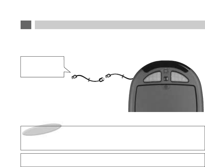
POWER CONNECTION
NOTE
The cable assembly used to connect the LSM104 to the 12Volt power supply varies depending on
product packaging.
MANUFACTURER : TEASUNG ELECTRIC CO.,LTD. TYPE# : AWM STYLE 1015
WARNING
The DC Battery Cord is ONLY for use with this model. Do not use it to power any other product
From Vehicle Battery:
RED: DC12V
BLACK: GROUND
DC Input Jack
CONNECTING TO CAR POWER

15
DOME LIGHT CONNECTION
(1) NEGATIVE Door Circuit
Red wire - Connect to 12V unswitched power.
Black wire - Connect to chassis ground.
This wire provides a ground. The lights will illuminate when the LSM104's 3-position dome
light switch is in the ON position. Failure to connect this wire to ground will prevent the
dome lights from illuminating with the switch in the ON position
White wire - Connect to negative door switch.
This wire will short to ground when a door is opened. The lights will illuminate if the
LSM104's 3-position dome light switch is in the DOOR position.
(2) POSITIVE Door Circuit
Red wire - Connect to chassis ground.
Black wire - Connect to 12V unswitched power.
If there is no constant power wire under the factory dome light, a constant power lead will
have to be run to a source of unswitched 12V power.
White wire - Connect to positive door switch.
This wire will have 12V power when a door is opened.
IMPORTANT NOTE - NEGATIVE & POSITIVE DOOR CIRCUITS:
The 3-wire harness for the LSM104's built-in dome lights is color-coded for use in vehicles that
employ a negative door circuit. This includes most US and imported vehicles.
Most Ford Motor Company vehicles and some imported vehicles employ a positive door circuit.
First verify which type of circuit is used in the installation vehicle and then follow the instructions in the
appropriate section below.
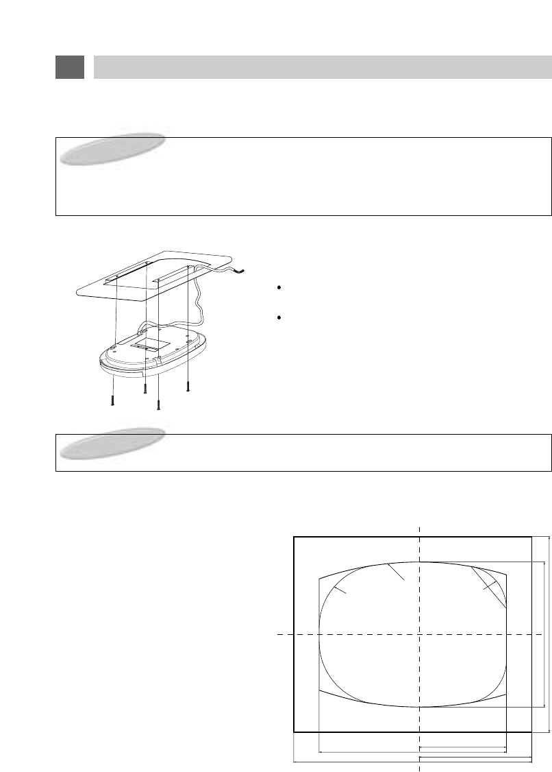
1. LSM104 INSTALLATION
EXAMPLE(Using optional mounting bracket)
Install the unit with 4 screws.
Use extreme care to insure that tools do not
damage the unit.
Use extreme care to insure that cutting tools
and/or mounting screws do not contact, cut or drill
through exterior body panels.
When the components are mounted with screws, be certain that the minimum thickness of the mount-
ing material is as follows:
Wood : 10mm or more
Metal : 3mm or more
Plastic : 4mm or more
2. LSM104 CUTOUT DIMENSIONS
A cutout template is packaged with this unit.
16
SET UP FOR CAR USE
NOTES:
The DC Power plug should not be accessible to the consumer.
WARNING:
UNDER NO CONDITION SHOULD THE LCD DISPLAY BE MOUNTED IN ANY POSITION WHERE A
PICTURE MIGHT BE VISIBLE TO THE DRIVER. EVEN IN THOSE CASES WHERE SUCH AN
INSTALLATION IS NOT PROHIBITED BY LAW, DOING SO MIGHT INCREASE THE LIKELIHOOD
OF A SERIOUS ACCIDENT.
394
2-R610.5
2-R126 2-R86
176
377
379 227
292
1. INITIAL PREPARATION
Insert batteries into the Remote Control unit by following the procedure described in the
"REMOTE CONTROL BATTERY INSTALLATION" section in this manual.
Follow the procedure described in the "MENU OPERATION" and "AUTO PROGRAM"
sections that follow to automatically scan and store active television channels into memory.
2. BASIC OPERATION PROCEDURE
1. Lowering the LCD Screen releases the AUTO POWER
SWITCH (see item #10 on page 8) and turns power on.
The input source last viewed will be automatically
selected.
If the screen is already lowered but power has been
turned off manually (or by the AUTO POWER OFF
function), press the POWER button on the LSM104
Control Panel or remote control to turn power back on.
2. Press the TV/VIDEO button on the LSM104 Control
Panel or Remote Control to select the desired mode
(TV, VIDEO 1, VIDEO 2, VIDEO 3).
3. If TV mode has been selected, select the desired channel using the CHANNEL /but-
tons on the LSM104 Control Panel or Remote Control. Pressing the /buttons
advances to the next lower or higher channel stored in memory.
Channels can be selected directly by using the 10-digit Keypad on the Remote Control.
Example: To select Channel 5, press "0" first, than press "5". (If "0" is not pressed first,
there will be a delay of about 5 seconds before the channel changes.)
4. If external speakers are connected to the EXTERNAL SPEAKERS OUTPUT CONNEC-
TOR, the VOLUME
-
/
+
buttons on the Remote Control may be used to adjust the speak-
er's volume.
The volume level will be shown on the screen with a
bar scale and a reference number (0-100) as shown.
17
LSM104 OPERATION
NOTE : The volume level can be muted instantly by pressing the MUTE button on the Remote
Control. See "MUTE Button" on page 26.
VOLUME 33
(1)
(2)
(3)
(4)
(3)
(4)
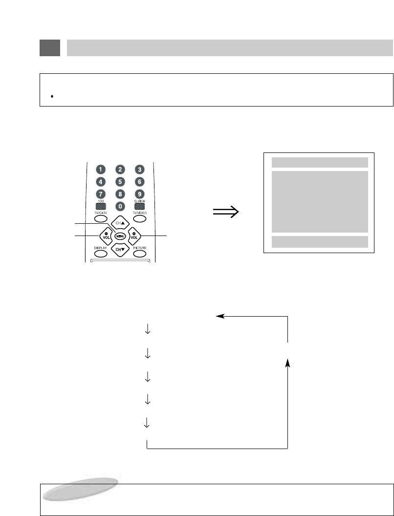
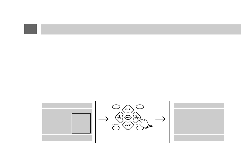
The MENU button gives you access to a variety of TV and Monitor functions.
1. Press the MENU button on the Remote Control.
The first time it is pressed, the following display appears on the screen.
Press the MENU button repeatedly to select the desired item for adjustment. Each time the button is
pressed, the selected item will change from WHITE to MAGENTA, indicating that it may be adjusted.
(1) AUTO PROGRAM Mode
(2) CHANNEL LIST Mode
(6) NO DISPLAY
(3) MTS Mode
(4) FM Mode
(5) FM FREQ.
(6) LANGUAGE Mode
2. After selecting the desired mode, press the VOLUME + button on the Remote control.
On-Screen Display
On-screen displays automatically disappear after about 5 seconds if no selection is made.
18
MENU BUTTON - GENERAL INFORMATION
MENU
AUTOPROGRAM
CHANNEL LIST
MTS : SAP
FM MODE OFF
FM FREQ.
LANGUAGE ENGLISH
MENU : NEXT
+
: ENTER
NOTE:
TV Broadcast related items -- AUTO PROGRAM, CHANNEL LIST & MTS -- are only shown in
the MENU display if the LSM104 is set to TV Mode.
(1)
(2)
(2)
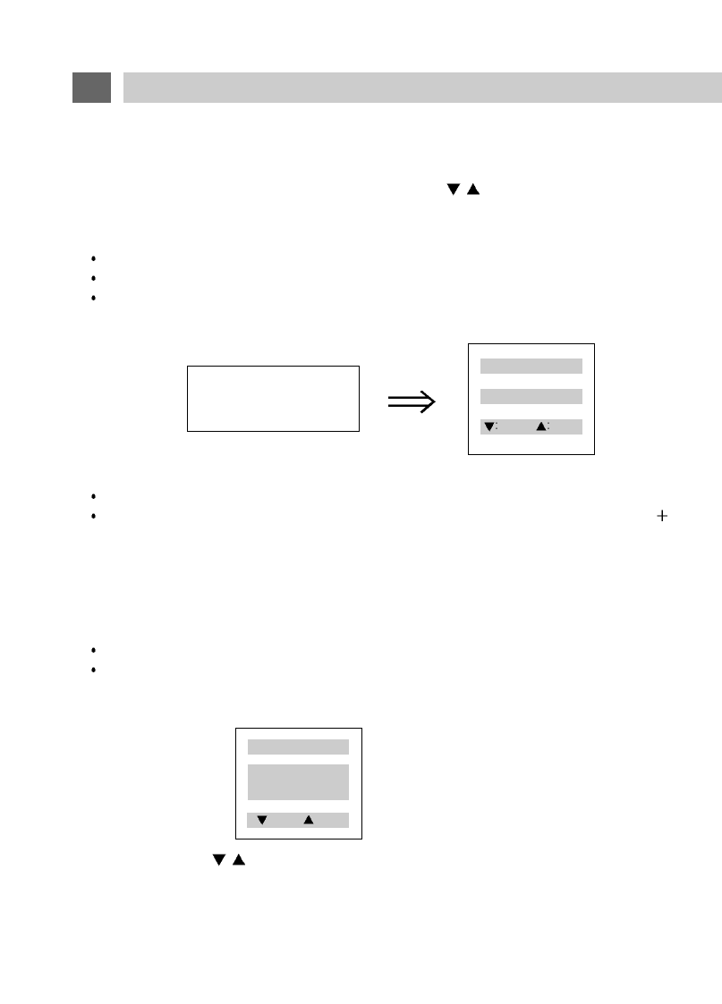
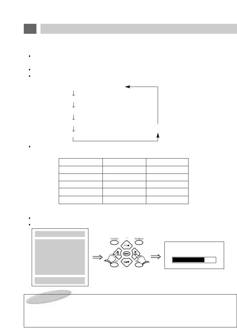
(1) AUTO PROGRAM
This function allows automatic memorization of all active TV channels in your viewing area. Once
memorized, channels can be selected with the CHANNEL /buttons on the Remote Control or on
the LSM104's Control Panel.
To activate AUTO PROGRAMMING.
Press the TV/Video button as necessary to switch to TV Mode.
Press the MENU Button until "AUTO PROGRAM" is selected.
Press the VOLUME button.
The following display will appear and the program set-up procedure will begin automatically.
All possible channels will be rapidly scanned and all active channels will be memorized.
Note that very weak broadcast signals will not be memorized.
If you wish to stop the Auto Programming procedure before it is finished, press the VOLUME button.
(2) CHANNEL LIST
You will note that the AUTO PROGRAM procedure generates and displays a CHANNEL LIST of the
active channels that have been stored in memory.
You may select channels directly from this list as follows:
Press the MENU Button until "CHANNEL LIST" is selected,
Then press the VOLUME + button.
A display of channels will appear:
Press the CHANNEL /buttons to select the channel you wish to view.
AUTO PROGRAMMING
5
+EXIT
19
MENU BUTTON - OPERATIONS
CHANNEL LIST
5 7 8 10 15
PREV. NEXT
CHANNEL LIST
5 7 8 10 15
18 20
PREV. NEXT
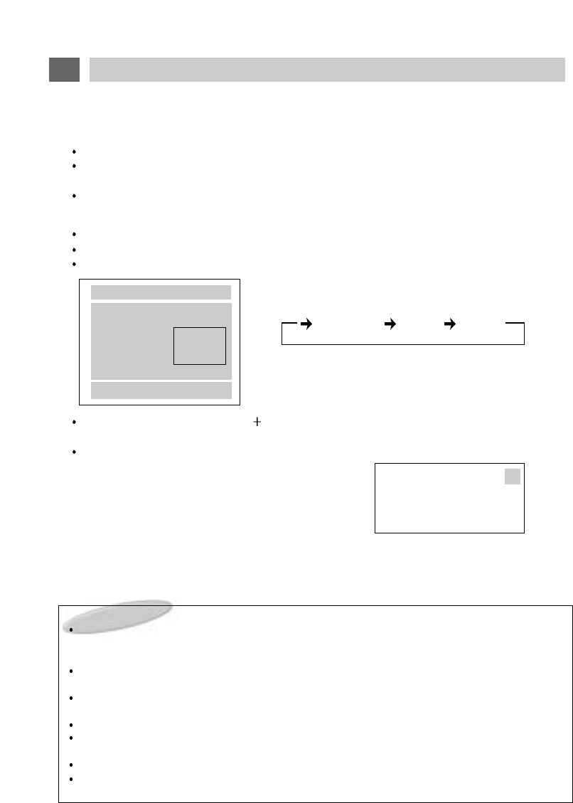
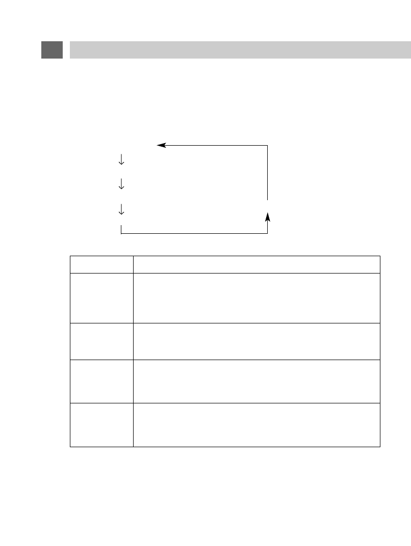
(3) STEREO / MTS
The LSM104 incorporates a STEREO/MTS (Multichannel Television Sound) decoder to receive:
STEREO broadcasts (if the station is broadcasting in Stereo)
SAP (Secondary Audio Program) broadcasts. SAP material might be an audio track in an additional
language, or it might be DVS information (Descriptive Video Service ) for the visually impaired.
MONO broadcasts
To select the MTS mode:
Press the TV/Video button as necessary to switch to TV Mode.
Press the MENU Button until "MTS" is selected.
A sub-menu will be displayed as shown below:
Each time you press the VOLUME button, the selection will change in the order STEREO - SAP -
MONO. The chosen mode will change from WHITE to MAGENTA.
Press the MENU button repeatedly until the menu disappears from the screen.
Whenever you change channels or switch the
LSM104 to TV mode, the MTS mode will be displayed
on screen after a brief delay as shown below.
In this example, the station is broadcasting both STEREO and SAP signals. You may also call up this
display at any time by pressing the DISPLAY button on the remote control.
If MONO mode has been selected, the on-screen display will not indicate a STEREO broadcast even if
it is available.
NOTES:
Reception of Stereo or SAP broadcast information is of course dependent on a television station actually
broadcasting such material. Not all stations do, and some stations only broadcast Stereo/SAP material
during part of the day.
If the LSM104 is set to STEREO and no stereo signal is being broadcast, a MONO signal will automati-
cally be received.
A stronger signal is required to receive Stereo or SAP broadcasts. If noise is heard, you can improve the
clarity of the audio signal by switching to MONO reception.
If a received SAP signal is weak, SAP will not be heard.
Some stations broadcast the same audio signal on the SAP band to insure that the viewer will still hear
audio if the television is accidentally set to SAP reception.
Even if both STEREO and SAP are broadcast, only one can be heard at a time.
Transmission of CABLE TV signals differ from off-air TV broadcasts. It is possible that MTS sound may
not be received satisfactorily.
20
MENU BUTTON - OPERATIONS
MENU
AUTOPROGRAM
CHANNEL LIST
MTS
FM MODE
FM FREQ.
LANGUAGE : ENGLISH
MENU : NEXT +-:ENTER
STEREO
SAP
MONO
STEREO SAP MONO
2
TV
STEREO SAP
21
MENU BUTTON - OPERATIONS
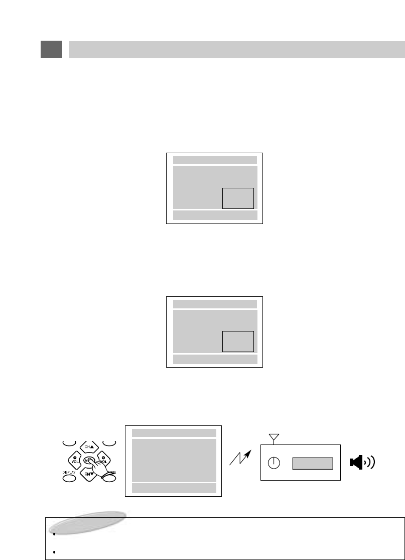
(4) FM BROADCAST MODE & FM FREQUENCY
The LSM104 has a built-in FM Stereo Broadcast Transmitter to allow you to listen to the audio signal from the
selected program source (TV, A/V1, A/V2, or A/V3) through the vehicle's FM radio.
Procedure
1. Press the MENU button as many times as necessary to select "FM MODE".
2. Press the VOLUME+ button as many times as necessary to set FM MODE as desired to "MODE1",
"MODE2" or "OFF".
3A. If "MODE1" was selected in Step 2 above, press the MENU button again to select "FM FREQ.",
then press the VOLUME - or + button repeatedly to choose one of the 4 preset FM Frequencies:
88.3MHz, 88.7MHz, 89.1MHz or 90.3MHz.
-OR-
3B. If "MODE2" was set in Step 2 above, press the MENU button again to select "FM FREQ.", then
press the VOLUME - or + button to choose any FM Frequency from 88.3MHz to 95.0MHz in
0.1MHz (100KHz) increments.
4. Tune the vehicle's radio to the frequency chosen in Step 3 above.
It may be necessary to repeat Step 3, choosing a different frequency each time, before you are able
to receive a satisfactory signal. The best signal is usually obtained by choosing a frequency that is
not actively broadcasting in your area. Also note that better results may be obtained if the vehicle's
antenna can be lowered independently.
Example - Receiving Audio through the FM Radio at 88.7MHz.
88.7MHz
SCAN FM
SPEAKER
<CAR RADIO>
NOTES TO INSTALLER
The FM Transmitter Antenna (Page 8 #19) should be installed in the direction of the vehicle's main
FM Antenna.
Never adjust the LA01 coil on the FM Transmitter board. It was optimally adjusted at the factory.
MENU
AUTOPROGRAM
CHANNEL LIST
MTS:STEREO
FM MODE
FM FREQ
LANGUAGE
MENU : NEXT + -:SEL
MODE1
MODE2
OFF
MENU
AUTOPROGRAM
CHANNEL LIST
MTS:STEREO
FM MODE
FM FREQ
LANGUAGE
MENU : NEXT + -:ADJ
88.3MHz
88.4MHz
95.0MHz
MENU
AUTOPROGRAM
CHANNEL LIST
MTS:STEREO
FM MODE MODE 1
FM FREQ. 88.7MHz
LANGUAGE ENGLISH
MENU:NEXT +:ENTER
22
MENU BUTTON - OPERATIONS
(5) LANGUAGE
The on-screen displays may be set to appear in your choice of 4 languages - English, Spanish,
Portuguese or French.
1. Press the MENU button repeatedly until "LANGUAGE" is selected.
2. Press the VOLUME
+
button as many times as necessary to select between "ENGLISH",
"ESPAÑOL", "PORTUGUÊS" and "FRANÇAIS".
MENU
AUTOPROGRAM
CHANNEL LIST
MTS:STEREO
FM MODE
FM FREQ
LANGUAGE
MENU:EXIT +:SEL
ENGLISH
ESPANÕL
PORTUGUÊS
FRANÇAIS
MENU
AUTOPROGRAM
CHANNEL LIST
MTS:STEREO
FM MODE NO
IDIOMA EXPAÑOL
MENU : NEXT + :SEL
The PICTURE button allows you to select each picture adjustment element.
Press the PICTURE button on the Remote Control or on the LSM104 Control Panel to bring up the
PICTURE Menu.
Press the PICTURE button repeatedly to select the item you wish to adjust.
The selected item will change from WHITE to MAGENTA, indicating that it may be adjusted.
(1) CONTRAST adjustment mode
(2) BRIGHTNESS adjustment mode
(3) SHARPNESS adjustment mode
(4) COLOR adjustment mode
(6) NO DISPLAY
(5) TINT adjustment mode
After selecting the desired mode, press the VOLUME - / + buttons to adjust the picture as you prefer
according to the chart below.
Example - Adjusting CONTRAST
Press the PICTURE button to display the PICTURE menu and select CONTRAST.
Press the VOLUME - / + buttons to call up and adjust the CONTRAST bar display.
23
PICTURE BUTTON
LIGHT
DARK
SOFT
SUBDUED
REDDISH
VOL
-
CONTRAST
BRIGHTNESS
SHARPNESS
COLOR
TINT
STRONG
BRIGHT
SHARP
VIVID
GREENISH
ITEM VOL
+
NOTES ON THE PICTURE FUNCTIONS:
Picture adjustments are only memorized if the STATUS Mode (see next section) is set to "CUSTOM".
Color LCD screens operate differently than conventional color picture tubes. As you operate the pic-
ture controls, you will notice that the range of adjustment is somewhat less dramatic than would occur
with a conventional picture tube.
CONTRAST 75
PICTURE
CONTRAST 75
BRIGHTNESS 50
SHARPNESS 50
COLOR 50
TINT 00
PIC : NEXT
The STATUS button on the Remote Control lets you select between a CUSTOM adjustable picture
setting mode or any one of 3 factory preset picture modes.
Pressing the PICTURE button repeatedly changes the mode as follows:
(1) CUSTOM mode
(2) STANDARD mode
(3) DYNAMIC mode
(5) NO DISPLAY
(4) MILD mode
PICTURE
MODE
Select this mode to view a picture that may be adjusted to your own
personal taste.
Note: While picture adjustments may also be made in the other 3
modes, adjustments will only be stored in memory in CUSTOM mode.
Select this mode to restore picture adjustments to the normal factory-
preset mode.
Select this mode to view a powerful and clear picture.
This mode is intended especially for viewing in brighter (daylight) envi-
ronments.
Select this mode to view a milder picture.
This mode is intended especially for viewing in darker (nighttime)
environments or to lessen eye fatigue.
STANDARD
CUSTOM
DYNAMIC
MILD
24
STATUS BUTTON
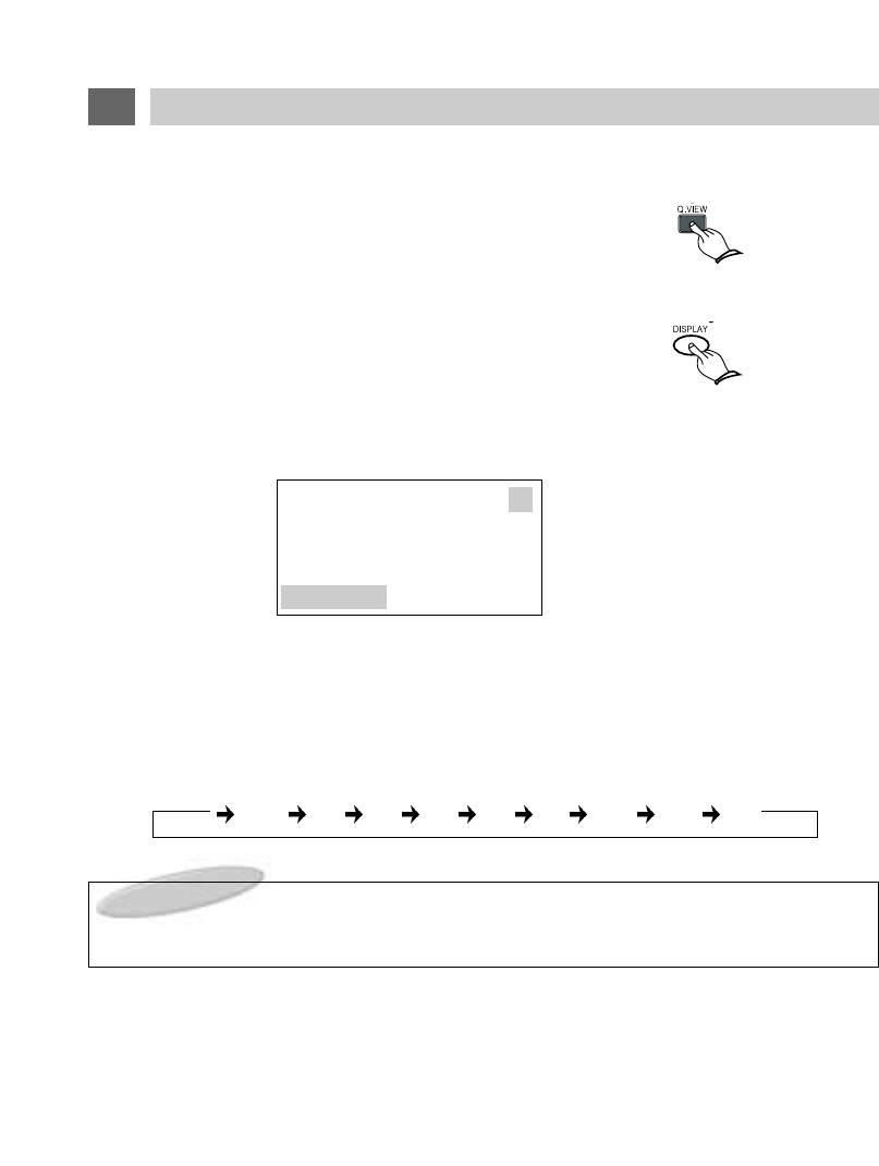
(1) QUICK VIEW Button
Press the Q. VIEW button on the Remote Control.
The previously viewed channel will appear on the screen.
Press Q.VIEW again to switch back to the original channel.
(2) DISPLAY Button
Press the DISPLAY button on the Remote Control.
The Program Source (Channel # & MTS mode, A/V1, A/V2 or A/V3) you are viewing and the set-
ting of the SLEEP TIMER will be displayed as shown.
(3) SLEEP Button
Press the SLEEP button to select a time period between 15 and 180 minutes after which the
LSM104 will automatically switch to power-off mode.
Repeatedly pressing the SLEEP button on the Remote Control cycles the SLEEP timer as shown
below.
NOTE :
To cancel the sleep timer function, press the SLEEP button repeatedly until the words
"SLEEP OFF" are displayed.
25
OTHER USEFUL FUNCTIONS
45
TV
SLEEP 30
OFF 15 30 45 60 90 120 150 180
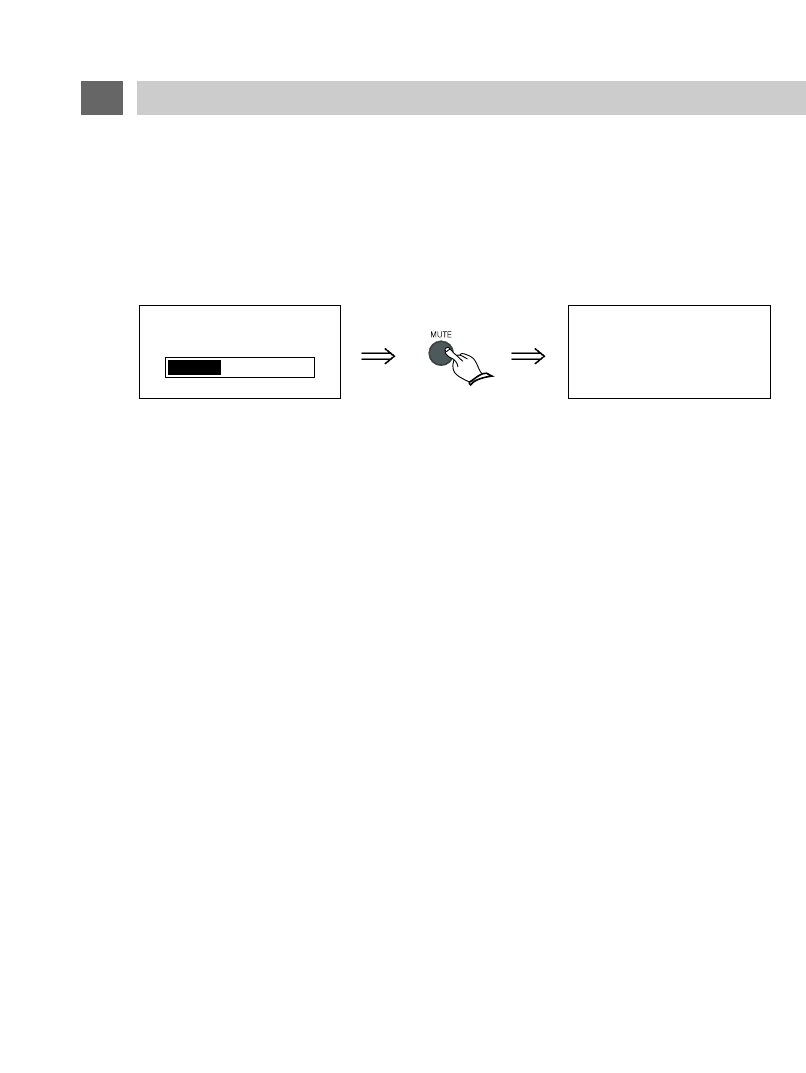
(4) MUTE Button
Press the MUTE button on the Remote Control.
Audio from any speaker(s) attached to the EXTERNAL SPEAKERS OUTPUT CONNECTOR will
be reduced to zero and "MUTE" will appear on the screen.
Pressing the MUTE button again will restore the audio to its original level.
(5) NOISE TIME Mode(Automatic power shut-off)
If the system is not switched off when a TV Station stops broadcasting, (or any other program
source ends) the system will automatically go to power off mode after approximately 15 minutes
have passed.
26
OTHER USEFUL FUNCTIONS
VOLUME 33
MUTE
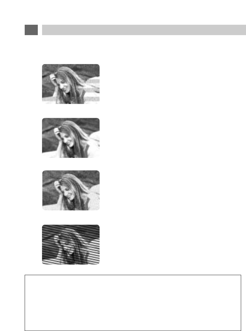
The most common types of television interference are as follows :
IGNITION NOISE:
Black spots or horizontal lines may appear, picture may
flutter or drift. Usually caused by interference from
automobile ignition systems, neon lamps, electric drills
and other electric appliances.
GHOSTS :
Ghosts are caused by the television signals following two
paths. One is a direct path and the other is reflected from
tall buildings, hills or other objects.
Changing the direction or position of the antenna may
improve the reception.
SNOW :
If you are located on the fringes of a television reception
area, the signal will be weak, and your picture may contain
many small dots.
When the signal is extremely weak, it may be necessary to
install an external sensitive antenna to improve the picture.
RADIO FREQUENCY INTERFERENCE :
This interference produces moving ripples or diagonal
streaks, and in some cases causes loss of contrast in the
picture.
IMPORTANT NOTE :
WHEN USED IN A VEHICLE, THIS SYSTEM IS INTENDED PRIMARILY AS A MONITOR FOR A
VIDEO CASSETTE PLAYER, VIDEO GAME, OR CAMERA.
TELEVISION BROADCAST RECEPTION WILL BE ADVERSELY AFFECTED BY CONDITIONS
SUCH AS MOTION, CHANGE OF DIRECTION, ATMOSPHERIC ACTIVITY, AND LOCAL SUR-
ROUNDINGS.
IT IS THEREFORE LIKELY THAT BROADCAST PICTURE QUALITY WILL BE MARGINAL WHEN
THIS SYSTEM IS USED IN A MOBILE ENVIRONMENT.
27
RECEPTION DISTURBANCE
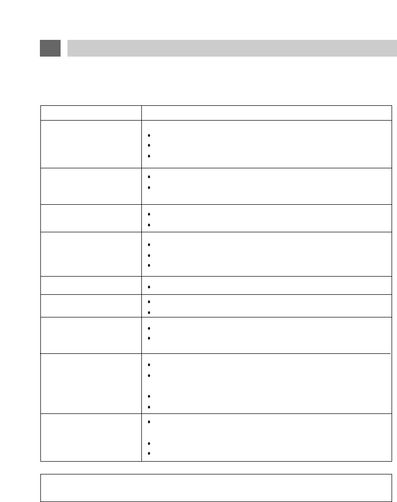
Before requesting service, please refer to the following chart for the symptom and possible solution.
For more information, see the corresponding page in this manual.
SYMPTOM
No image, no sound Is the system receiving power? (page 14)
Is the TV/VIDEO selector set properly? (page 13)
Are connections to other equipment properly made? (page 12~13)
Sound but no image Are contrast and brightness adjusted properly? (page 23)
Are video connections from other equipment properly made?
(page 12~13)
Unstable picture on screen Is antenna cable connected and located properly? (page 12)
Is broadcast signal strong enough for proper reception?
Power Off
Has there been a no-signal condition for 15 minutes or more?
(page 6)
Is the system receiving power? (page 14)
Are any external fuses blown?
Multiple image or ghosts
on the screen
Is the antenna located properly? (page 12)
Are delayed reflected signals being received from tall buildings or
mountains
?
Remote Control
operating poorly or not
at all
Is remote control aimed at the remote sensor?
Are there any obstacles between remote control and remote
control sensor?
Is Remote control within working distance?
Are batteries fresh and inserted properly? (page 11)
Noisy picture Is antenna cable connected properly? (page 12)
Is broadcast signal strong enough for proper reception?
No sound or volume
control does not operate
Are speakers connected?
Is MUTE set to on?
Are audio outputs properly connected? (pages 13, 21)
Poor color Are COLOR & TINT adjusted properly? (page 23)
CHECKING POINTS
NOTICE : For additional information or the location of an authorized service center please contact
KEC Mobile Applications/KTV Inc. at (800) 524-1216 or (973) 470-9191.
28
TROUBLESHOOTING GUIDE
Unified Remote Controller (LSM-104 + KEC Mobile Applications VCP's)
AAA Cells X 2
A/V 1 Extension Cable
Supplied 12V DC Input Power Extension Cable
External Speakers Extension Cable
Installation & Operating Manual
Installation Cutout Template
Warranty Card
Optional Metal Housing Frame
Universal Trim Ring
Molded Consoles for a variety of specific vehicles
ACCESSORIES
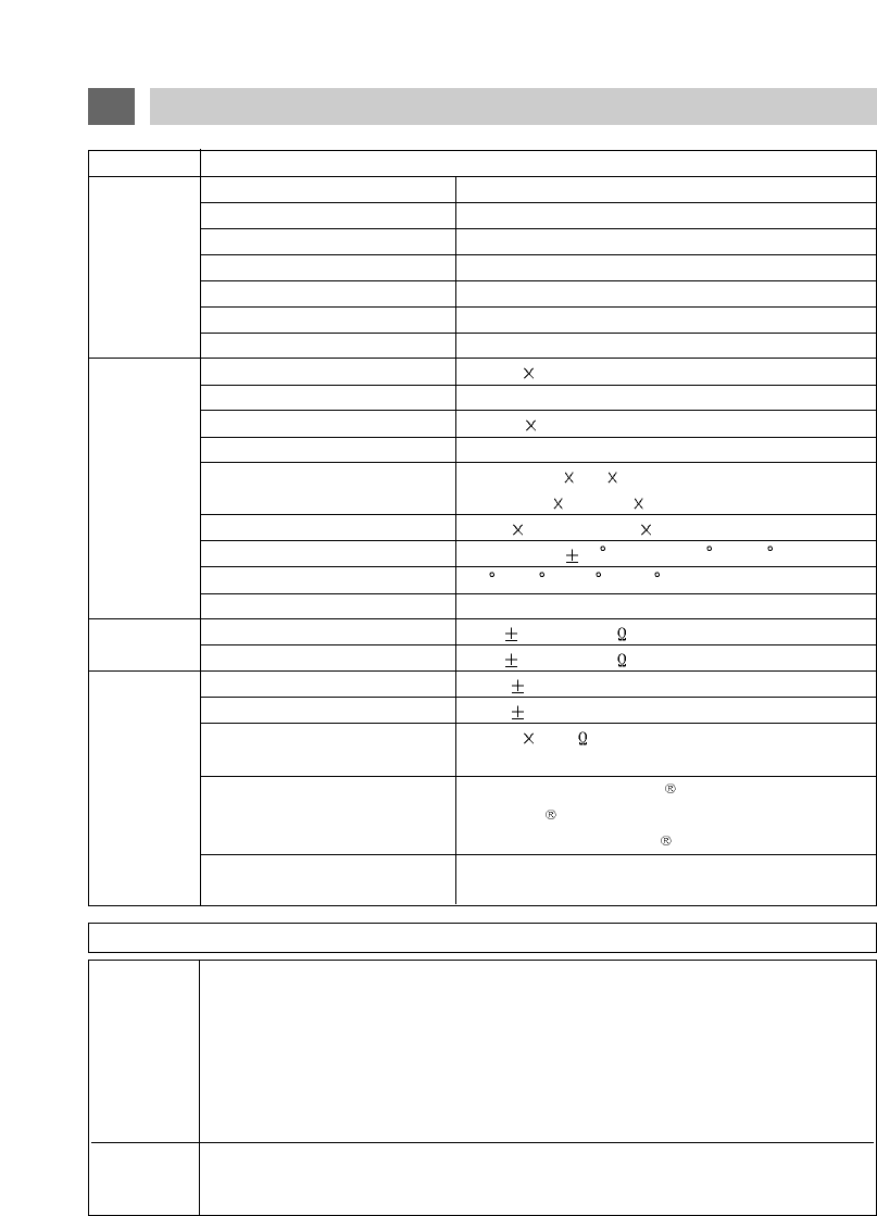
SPECIFICATIONS
ITEM SPECIFICATION
Display Panel 10.4 Inch TFT LCD
Television System NTSC-M
GENERAL Tuning System Frequency Synthesizer
Receiving Channels VHF 2~13/UHF 14~69/+113 CATV
Antenna Impedance UHF/VHF 75 Ohm
Power Source DC 12Volt(Car Battery)
Power Consumption 22W (DC 12V)
High Resolution Picture 800H 600V=480,000Pixels
Contrast Ratio 250:1 Typical
Pixel Pitch 0.264 0.264(mm)
Pixel Configuration RGB Stripe Arrangement
DISPLAY
LCD Panel Dimension (WHD)
8.8" 6.8" 0.22"
SCREEN
(224.5mm 172.0mm 5.7mm)
Active Screen Area 8.3" 6.2"(211.2mm 158.4mm)
Off Axis Viewing Range Horizontal: 45 / Vertical:10 Up, 30 Down
Operating Temperature 0 C~50 C / 32 F~122 F
Operating Humidity 35% ~ 85%
VIDEO Input Level 1.0 0.1 Vp-p(75 Load)
Output Level 1.0 0.1 Vp-p(75 Load)
Input Level 400 50mVrms(RCA Jacks)
Output Level 400 50mVrms(RCA Jacks)
AUDIO External Speakers Outputs 2.0W 2@4 , <10% THD(Variable)
(ALL Hum< 3mVrms / Buzz <200mVp-p
STEREO) Wireless IR Transmitter
Compatible with Unwired brand IR Headphones
(Unwired Technology LLC) and other brands
compatible with Unwired .
Wireless FM Broadcast Modulator Off + 4 Preset Frequencies + Any Frequency
Between 88.3 MHz~95.0 MHz In 100 kHz Steps
29