KZ Broand Technologies ISURF1000A1 WIFI VOIP GATEWAY User Manual iSurf 1000
KZ Broadband Technologies, Ltd. WIFI VOIP GATEWAY iSurf 1000
Users Manual
iSurf 1000 Multi-Service Home Gateway
User Operation Manual
Version 1.1
KZ BROADBAND TECHNOLOGY Co. Ltd. CONFIDENTIAL
This document and the information contained in it is confidential information of KZ Broadband Technologies Ltd (KZ Tech),
and shall not be used, or publish, or disclosed, or disseminated outside of KZ Tech in whole or in part without KZ Tech’s
consent. This document contains trade secrets of KZ Tech. Reverse engineering of any or all of the information in document
is prohibited. The copyright notice does not imply publication of this document
© COPYRIGHT 2004-2012, KZ Broadband Technology Co. Ltd.
CONFIDENTIAL INFORMATION
Information contained herein is proprietary to KZ Tech for whose benefit
confidentiality shall be maintained.
iSurf 1000 User Operation Manual
- 2 -
1. Packing List
The product is shipped with the following standard accessory and parts. The user should contact the local distributor
if there is any part missing.
Content Quantity
Main System Unit 1
12V DC Power Adapter 1
RJ45 Ethernet Cable 1
Quick User Manual 1
Product Warranty Card 1
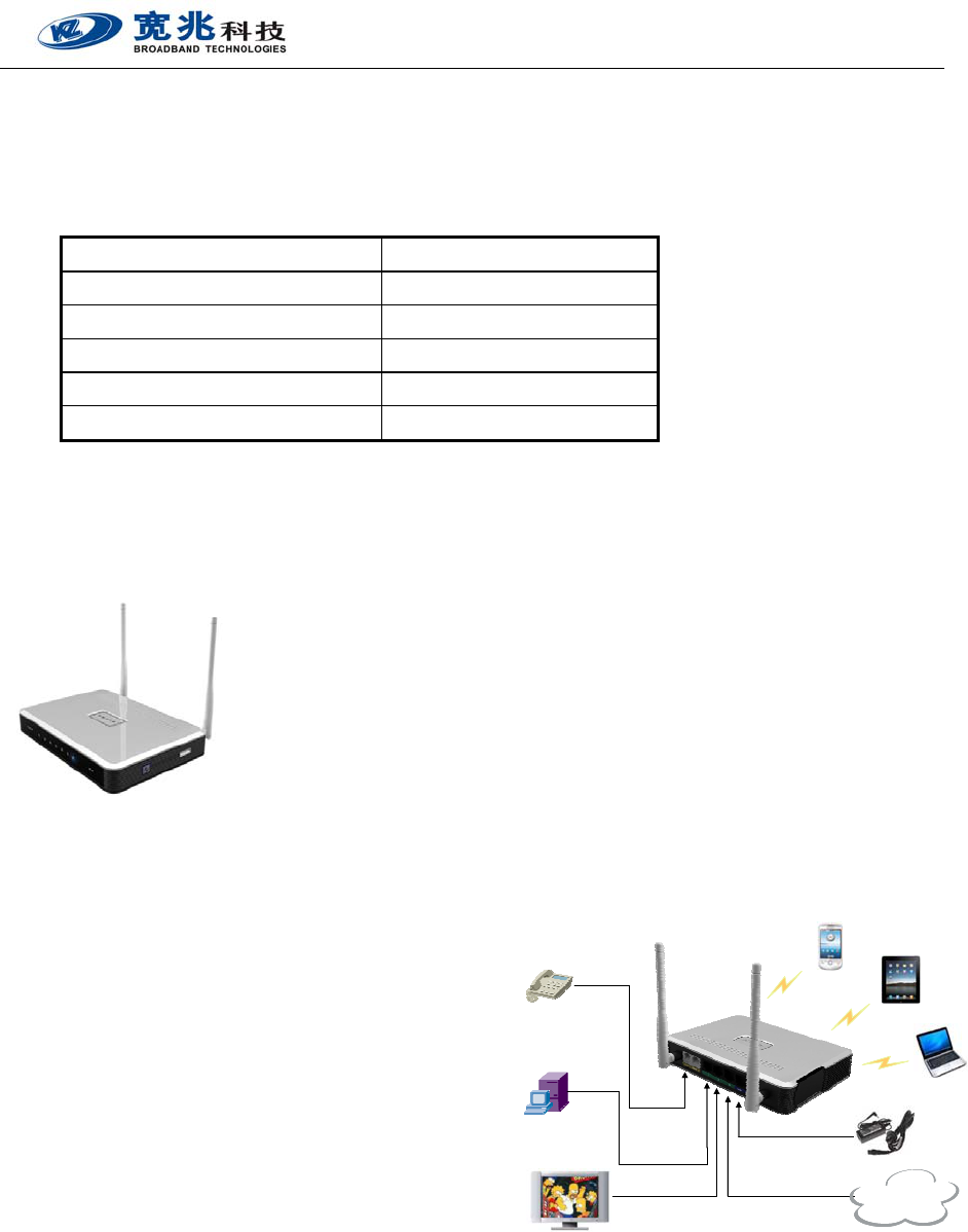
2. Introduction
The iSurfTM 1000 multi-service home gateway is a state of art home gateway
product specially designed to provide integrated broadband services to residential
or SOHO customers. It allows broadband service provider to offer triple play
services (data, VoIP, WiFi) to its residential customers at extremely affordable cost.
The product offers a variety of user networking interfaces including LAN Ethernet
ports, analog phone line ports, master USB port and 802.11n/g/b WiFi interfaces.
User can easily connect multiple PC or LAN devices to the unit via Ethernet or WiFi interfaces while having reliable
VoIP phone service at same time. The USB port provides addition flexibility to connect USB devices such as camera,
sensor or 3G modem to further expand the service offering.
The iSurfTM 1000 is developed using single SoC silicon solution
and most advanced soft DSP processing technologies to
maintain the best performance and cost in home gateway
design. It also provides extensive feature and service
capabilities in data, SIP VoIP and Wi-Fi networking. Its unique
hardware NAT acceleration technique allows the product to
achieve extremely fast data throughputs even in router
operation mode. In addition to the advanced networking
capabilities, iSurfTM 1000 also provides rich management
interfaces to allow local and remote device management. Its user friendly WEB management interface is well
designed to provide quick installation and setup for user as well as advanced configuration for the device
administrator.
The product detail specification is provided by the below section.
iPad
Phone
or Fax
PC
xDSL/Cable/GEPON
Set-top boxes
Notebook
Dual Mode
WiFi Phone
Power DC 12V
ETH
Internet
iPad
Phone
or Fax
PC
xDSL/Cable/GEPON
Set-top boxes
Notebook
Dual Mode
WiFi Phone
Power DC 12V
ETH
InternetInternet

iSurf 1000 User Operation Manual
- 3 -
3. Product Specification
PHYSICAL
Dimensions 135mm (L) x 105mm (W) x 30mm (H)
Weight < 300g
Power < 10 Watts
Power Supply 12V DC
ENVIRONMENTAL
Temperature -10 ℃ - 50 ℃
Humidity 90% maximum Non-condensing
Storage -20℃- 65℃
SYSTEM
Interface 1 10/100M Ethernet WAN Port (RJ45)
802.11n/g/b WiFi (2.4GHz)
3 10/100M Ethernet LAN Ports (RJ45)
2 Analog Phone Ports (RJ11)
1 USB OTG Port (2.0)
System LEDs Power, WAN, WLAN, LAN1-3,
Phone, Voice Mail
Line Distance > 1 km
WIRELESS
Standards IEEE 802.11n, IEEE 802.11g&b
Radio 2.4-2.497GHz (2x2 MIMO)
20dBm ± 1dB per antenna
Antenna Two 3dBi dipole external antennas
Security 64/128 bit WEP encryption
WPA/WPA2/WAPI authentication
WPS (WiFi Protected Setup)
QoS Support WMM, WMM Power Save
Networking Private home networking
Virtual public networking
VOIP PROCESSING
Compression G.711 a
G.711 u
G.729
G.721
Comfort Noise Comfort noise generation and control
Echo Cancellation G.165/G.168-2000 echo cancellation
Silence Suppression Silence detection and suppression
Fax Support T.30 and T.38
Delay/Jitter/Loss Delay, jitter, packet loss compensation
DTMF Relay In-band DTMF, RFC 2833, SIP signal
Call Duration > 48 hours Uninterrupted Call
VOICE SERVICE
Basic Voices
Local and domestic and international long distance calls
Flexible dial plan configuration support
Tone customization for different countries
Complementary Services
Caller ID, Caller ID suppression, Call Screening, Speed
dial, Call Tracing, Hotline, Unconditional call forwarding,
Call Forwarding No Answer, Call Forwarding on Busy,
Call Waiting, Call Back, Call Blocking, No Disturbance,
Alarm, Network and Local 3-way Call, Data Call, and etc.
Billing Service Support
Z interface polarity reversal
NETWORKING CAPABILITIES
Data Networking
Router and Bridge operation mode support
WAN DHCP or static IP address assignment
L2TP, PPTP and PPPoE client support
DHCP and NAT service for LAN and WiFi devices
SPI Firewall and DMZ support
VPN Pass-through support (PPTP / L2TP / IPSec)
Support for DNS, NTP, TFTP, FTP services
QoS and VLAN management support (coming release)
VoIP Networking
Soft switch based network configuration
Device peer to peer networking support
INDUSTRY STANDARDS
IEEE
IEEE 802.3 10Base Ethernet
IEEE 802.3u Fast Ethernet
IEEE 802.1p CoS Priority Protocol
IEEE 802.1Q VLAN Tagging
IETF
IP voice SIP v2.0
MANAGEMENT
User Management Telnet, Web, Console (debug)
Others FTP Auto Firmware Upgrade
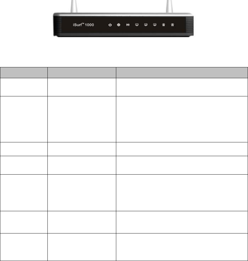
4. Front Panel Description
Table 1 Front Panel LED Specification
LED Function Description
PWR Power supply indicator,
dual color LED
Orange Color – Device is booting up
Green Color – Device in normal operation
WAN
WAN port status LED
( dual color)
Orange Color – Device WAN port is not yet ready for
normal operation.
Solid Green – Device WAN port is up and ready.
Blinking Green – WAN port data transmission in
progress.
WiFi WiFi status indicator Green Color – WiFi is enabled and working
LAN 1-3 LAN port status Solid Green – The LAN port is up
Blinking Green – LAN data transmission in progress
PHONE POTS line status indicator
(dual color)
Orange Color – Line hardware problem
Green Blinking – Voice Call in progress
Green Color – The line is ready and registered
OFF – Line is not registered or provisioned.
Voice Mail Indication of the existence
of new voice mail
Green – New voice mail available
WPS (Left Side) WPS Service Access Orange Blinking – WPS access is enabled. The
procedure can be triggered by pressing the WPS
button.
iSurf 1000 User Operation Manual
- 5 -
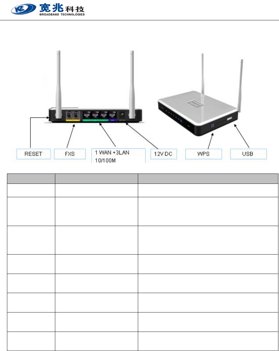
5. Rear Panel Description
Interface Function Description
12V DC Power connector DC Power Supply with harmonic suppression: 12V 1.5A.
Reset Device Restart and Factory
Default Reset
Press and immediate release: reboot the device.
Press and hold (10 seconds): Reset the device to factory
default settings. User configuration data will be deleted.
WPS Wi-Fi Protected Service Access Press the WPS button to begin automatic user access
process. The LED will be blinking during the negotiation
and login process.
WAN WAN ETH Port (RJ45) Connect to ADSL modem or IP network for Internet
access
LAN 1-3 LAN ETH Port (RJ4) Connect to PC, LAN Switch or Ethernet networking
equipment.
FXS Ports 1-2 Analog Phone jack (RJ11) Two independent voice line to connect to analog phone
or fax machines.
USB USB 2.0 OTG Networking
Interface
Used for connection 3G or 4G USB devices. Support plug
and play for instant networking.
WiFi WiFi Antenna (2x2 MIMO) Support 2x2 MIMO 802.11b/g/n, Up to 300Mbps
maximum speed.
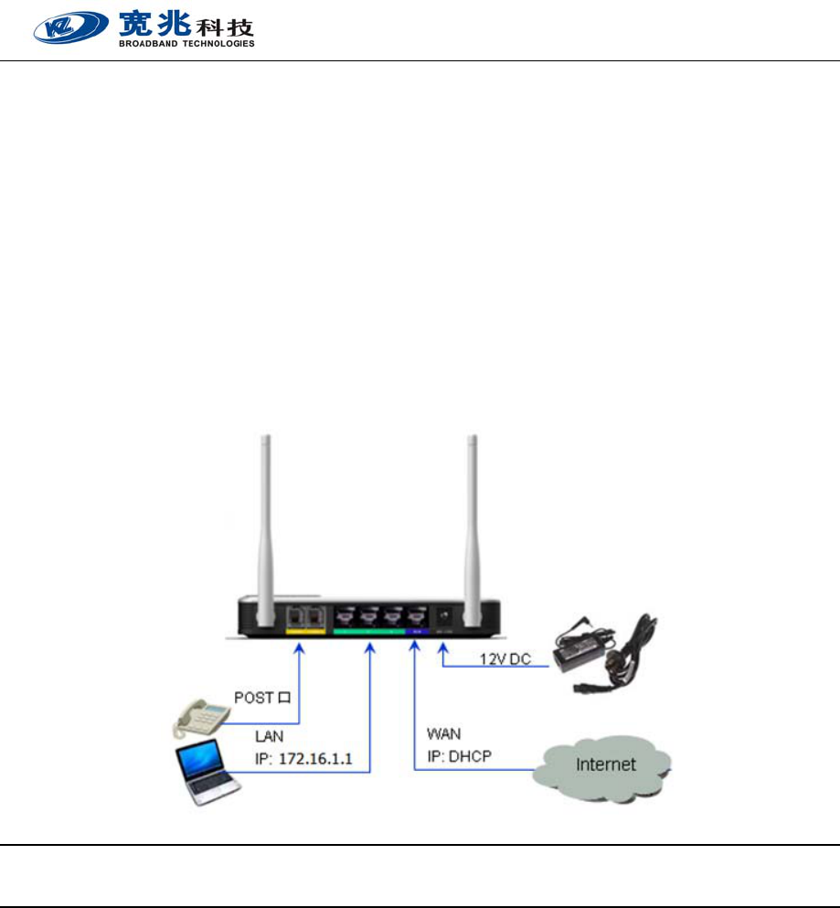
6. Installing Device
Before installing the device, please make sure you have applied and activated the internet service from your service
provider. To install the device, the user should follow the steps below. For safety, please keep your hand dry when
operating the device.
【1】 Open the packing box and take out the device. Place the device on table and rotate the WiFi antenna
upwards.
iSurf 1000 User Operation Manual
- 6 -
【2】 Check the product label carefully and make sure the device S/N and MAC is clearly visible.
【3】 Connect your PC to the one of the LAN port using regular Ethernet cable.
【4】 Connect the device WAN port to the ADSL modem or other uplink networking devices via Ethernet
networking cable.
【5】 Connector analog phone cables to the RJ11 ports of the device.
【6】 As a last step, connect the DC power supply and plug the DC power adapter into AC power source. Make
sure the AC supply is compliant to the power supply specification of the device.
【7】 When the above is done, the device will start to boot up. Please wait until the PWR LED becomes green
before proceeding to the device configuration stage.
【8】 A typical networking diagram is shown below for illustration.
Note: LAN Management IP Address: 172.16.1.1, PC Networking Setup Requirement: DHCP Client
WEB configuration can be access via http://172.16.1.1
7. Device Configuration
The device provides simple and easy user configuration via WEB GUI interface. User can use common Internet
Explorer software for configuration of the device. If you are first time user, please access the WEB management
interface via the LAN port. iSurf 1000 supports DHCP server and NAT function by default so the user only need to
configure the PC network setting to use DHCP. The LAN PC can easily acquire its IP address from the device once the
network setting is configured properly.
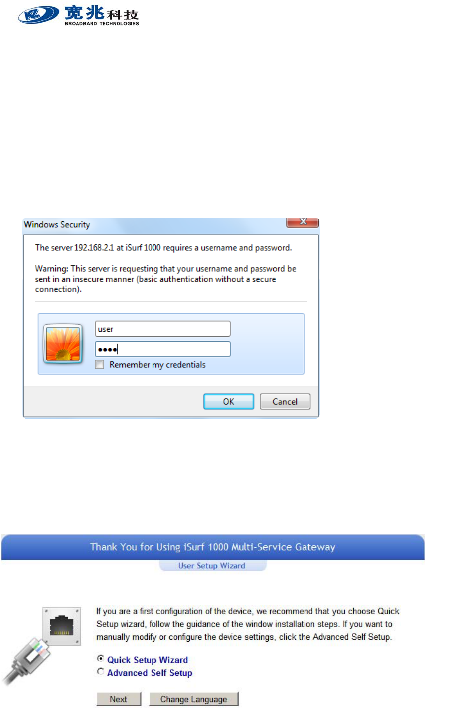
The device default WEB management access IP is 172.16.1.1. Once the user PC acquires the IP, open the Internet
browser and enter the URL of http://172.16.1.1 to login into the WEB GUI. If enter correctly, the login window will
pop up. The user can enter “user” as the login ID and the password to gain access.
The user WEB GUI provides simple Setup Wizard to guide ordinary user to complete the device setup quickly. The
iSurf 1000 User Operation Manual
- 7 -
user also has the option to navigate the configuration menu to complete the setup.
For advanced user or system operator, the admin level WEB GUI management interface is available. It requires
special admin password to gain full access of the device and configure the devices. Note admin level management
function is not described in this manual.
Login
Once the user enters the correct URL (http://172.16.1.1), the following login window will be prompted. The user can
type “user” and “user” as Login ID and password to begin login process. The user management GUI allows user to
configure essential setting required for device operation.
Selection of Configuration Method
Once the user is logged in, the following window will be prompted for selecting the method to configure the device.
For regular user, please select and use the setup Wizard to complete the device setup. The setup Wizard will guide
the user to quickly finish the setup configuration alone with the online help. If the user is familiar with the
configuration, he can choose self setup approach to configure the device.
iSurf 1000 User Operation Manual
- 8 -
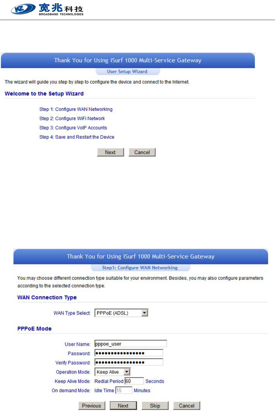
Setup Wizard
Select the “Setup Wizard” and click on the “Next” to enter Wizard welcome page as shown below.
The quick Wizard setup is divided into four steps:
Step 1: Configure WAN Networking
Step 2: Configure WiFi Network
Step 3: Configure VoIP Accounts
Step 4: Save and Restart the Device
Step 1: Click on the “Next” to enter WAN Networking Setup Window
In the Internet Connection selection, the user can select one of the three common used ways (Static IP, DHCP,
iSurf 1000 User Operation Manual
- 9 -
PPPoE) to connect to Internet based on his access network type. If the user is not sure about the type of access
type he should use, please consult with the service provider.
For PPPoE dial up Internet access, the user will be required to configure the User name and Password for PPPoE
dial up access. The user can also select the appropriate operation mode he needs.
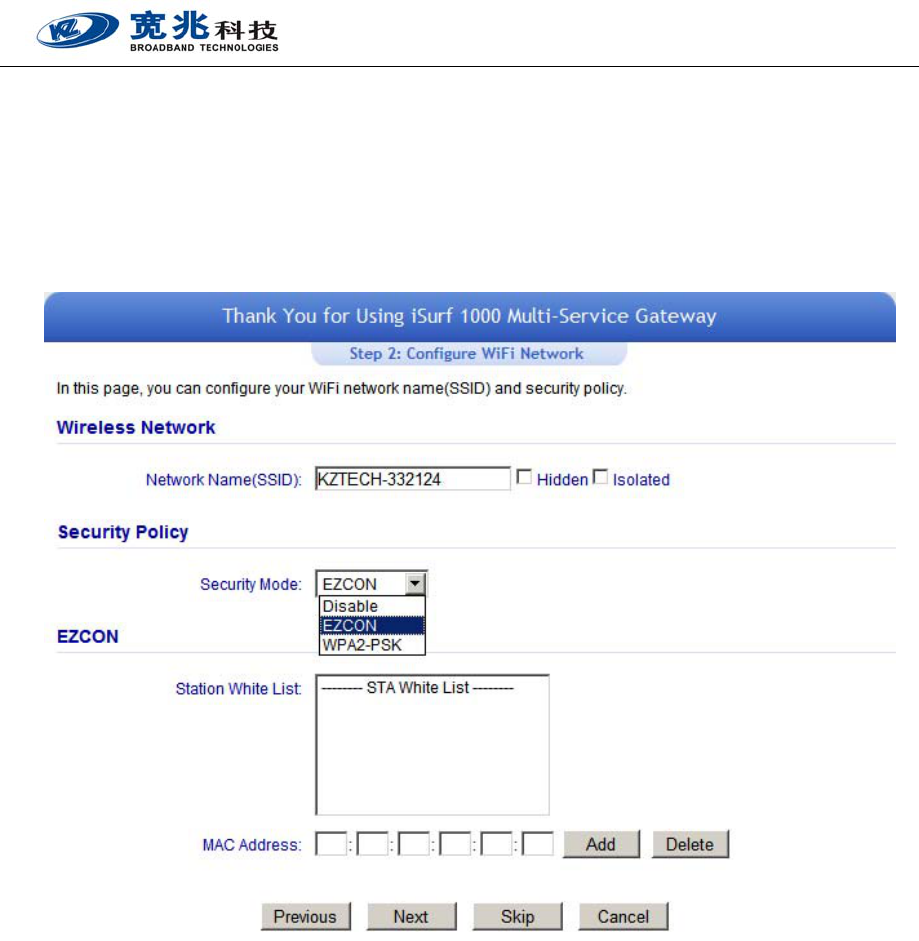
Step 2: After completing the WAN configuration, click “Next” to enter WiFi configuration
In WiFi configuration, the user can modify the default SSID and select the desired Security Policy to protect
device WiFi access. For easy configuration, the user can use one of the following three common security
policies for setup.
Disable Open access to every device. It is typically used for temporally use only.
EZCON Use KZ TECH innovative security protection for easy WiFi access protection. When the WPS
button is pushed, the WiFi access will become open to all devices for 60 seconds. The open
access times out, a white list access control will be enforced.
WPA2-PSK The most commonly used standard WiFi Security policy.
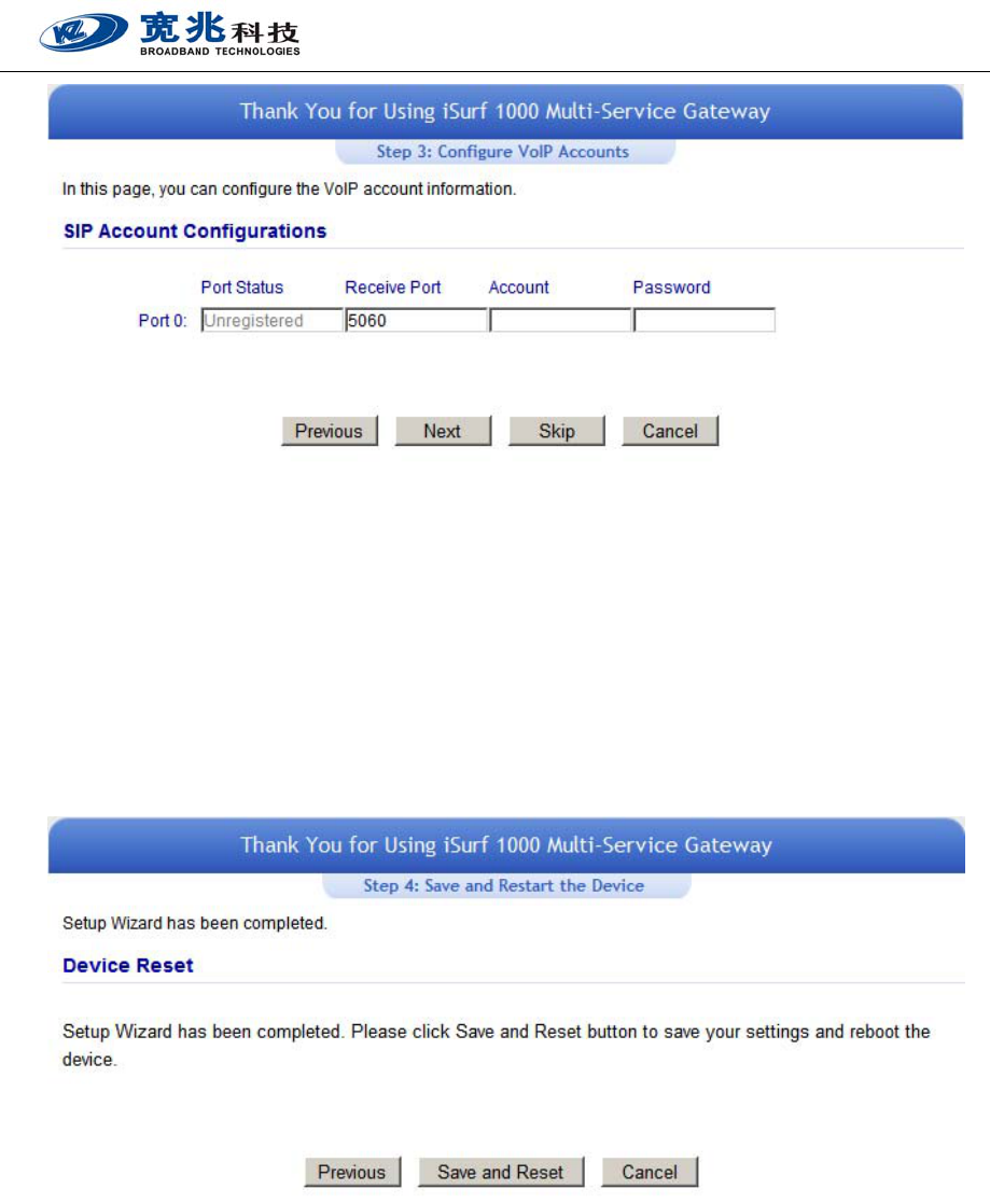
Step 3: Click “Next Step” to enter VoIP account configuration menu
iSurf 1000 User Operation Manual
- 10 -
In this configuration page, the user requires to enter the SIP account and password information if he desires to
configure the VoIP networking. The SIP server configuration will be performed by the network operator via
admin management. The SIP account status is displayed for user information. When the SIP line is registered
and ready, the LINE LED in the front panel will be light up.
If the device VoIP function is not working properly, the user is advised to contact the network operator for
assistance.
Step 4: Click “Next” to complete the VoIP account setup and enter Save & Restart menu
For all the configuration changes to take effect, the user is required to save the configuration and perform a
device restart. Click on the “Save and Restart” button to complete the Wizard setup and begin to use the
device.
iSurf 1000 User Operation Manual
- 11 -
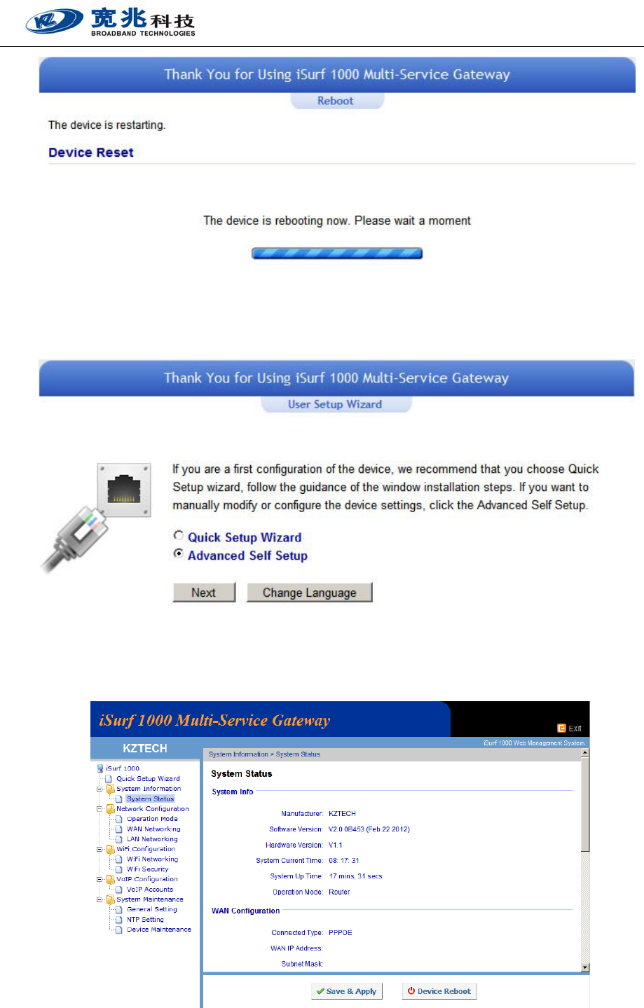
Once the device restarts, please wait for a few minutes until the following windows appear again.
The user may select “Advanced Self Setup” to quickly review and confirm the all setup. Click “Next” to proceed
and enter the Self Setup menu as below.
iSurf 1000 User Operation Manual
- 12 -
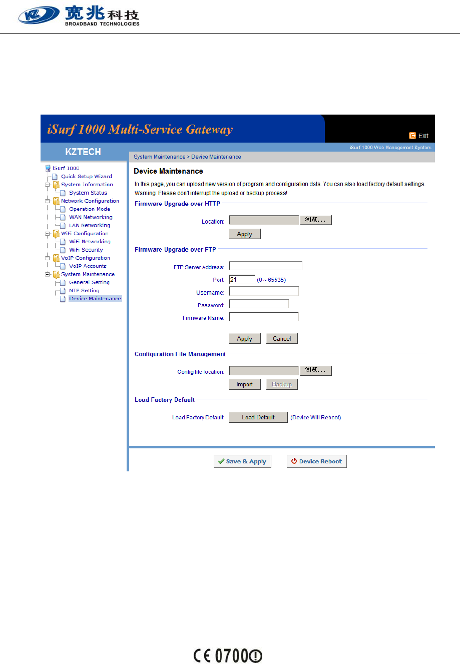
For device maintenance operation, the user can use Device Maintenance menu to perform the operation
required. There are three type maintenance operations are supported by user level management: 1) Update
Device Firmware 2) Import Device Configuration File 3) Reset Device Configuration to Operator or Factory
Default.
8. General Information
RF exposure information: The Maximum Permissible Exposure (MPE) level has been calculated based on a
distance of d=20 cm between the device and the human body. To maintain compliance with RF exposure
requirement, use product that maintain a 20cm distance between the device and human body.
The adapter shall be installed near the equipment and shall be easily accessible.
EU Regulatory Conformance
Hereby, KZ Broadband Technologies, Ltd. declares that this device is in compliance with the essential
requirements and other relevant provisions of Directive 1999/5/EC.
For the declaration of conformity, visit the Web site www.kztech.cn .
Notice: Observe the national local regulations in the location where the device is to be used. This device may be
restricted for use in some or all member states of the European Union (EU)

iSurf 1000 User Operation Manual
- 13 -
FCC Notice to user
This device complies with part 15 of the FCC rules. Operation is subject to the following two conditions: (1) this
device may not cause harmful interference, and (2) this device must accept any interference received, including
interference that may cause undesired operation.
NOTE: The manufacturer is not responsible for any radio or TV interference caused by unauthorized modifications
to this equipment. Such modifications could void the user’s authority to operate the equipment.
NOTE: This equipment has been tested and found to comply with the limits for a Class B digital device, pursuant to
part 15 of the FCC Rules. These limits are designed to provide reasonable protection against harmful interference
in a residential installation. This equipment generates uses and can radiate radio frequency energy and, if not
installed and used in accordance with the instructions, may cause harmful interference to radio communications.
However, there is no guarantee that interference will not occur in a particular installation. If this equipment does
cause harmful interference to radio or television reception, which can be determined by turning the equipment off
and on, the user is encouraged to try to correct the interference by one or more of the following measures:
- Reorient or relocate the receiving antenna.
- Increase the separation between the equipment and receiver.
-Connect the equipment into an outlet on a circuit different from that to which the receiver is connected.
-Consult the dealer or an experienced radio/TV technician for help