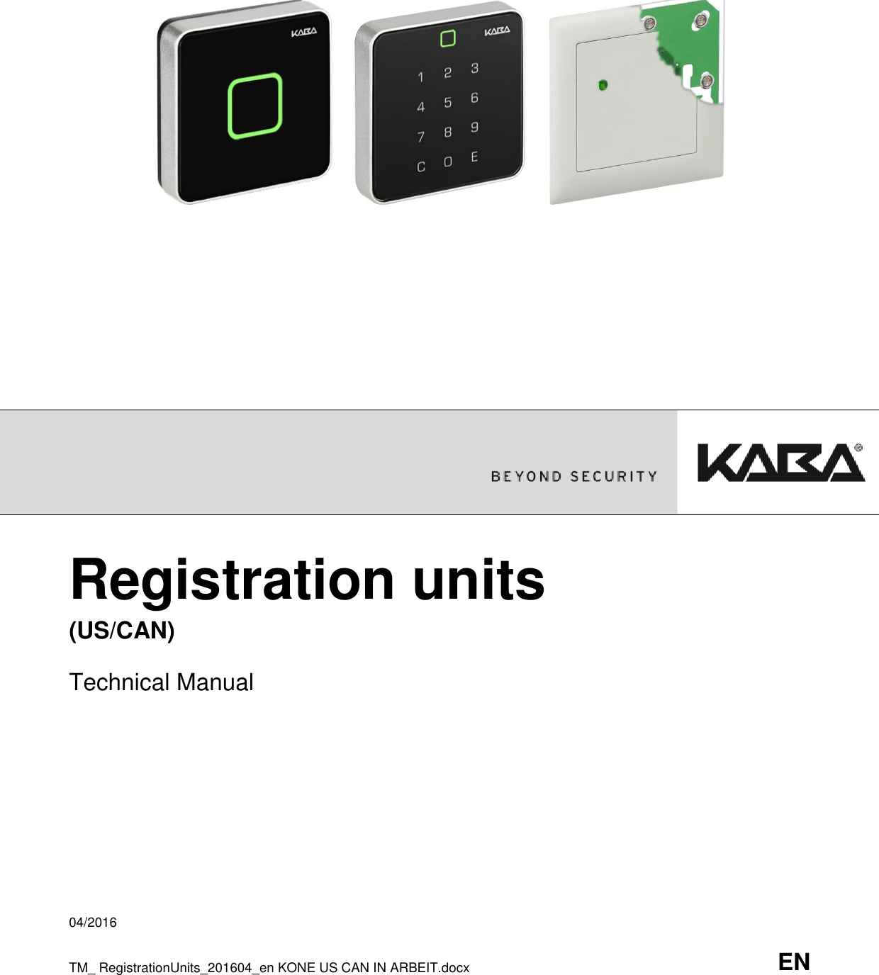
Kaba KAM9200-K5 Desktop Reader User Manual Configuration Manual
Kaba GmbH Desktop Reader Configuration Manual
UserManual.wiki
>
Kaba
>
KAM9200 K5 User Manual
user manual
Navigation menu
Upload a User Manual
Namespaces
Wiki Guide
HTML
PDF
Info
Views
User Manual
Discussion / Help
Navigation
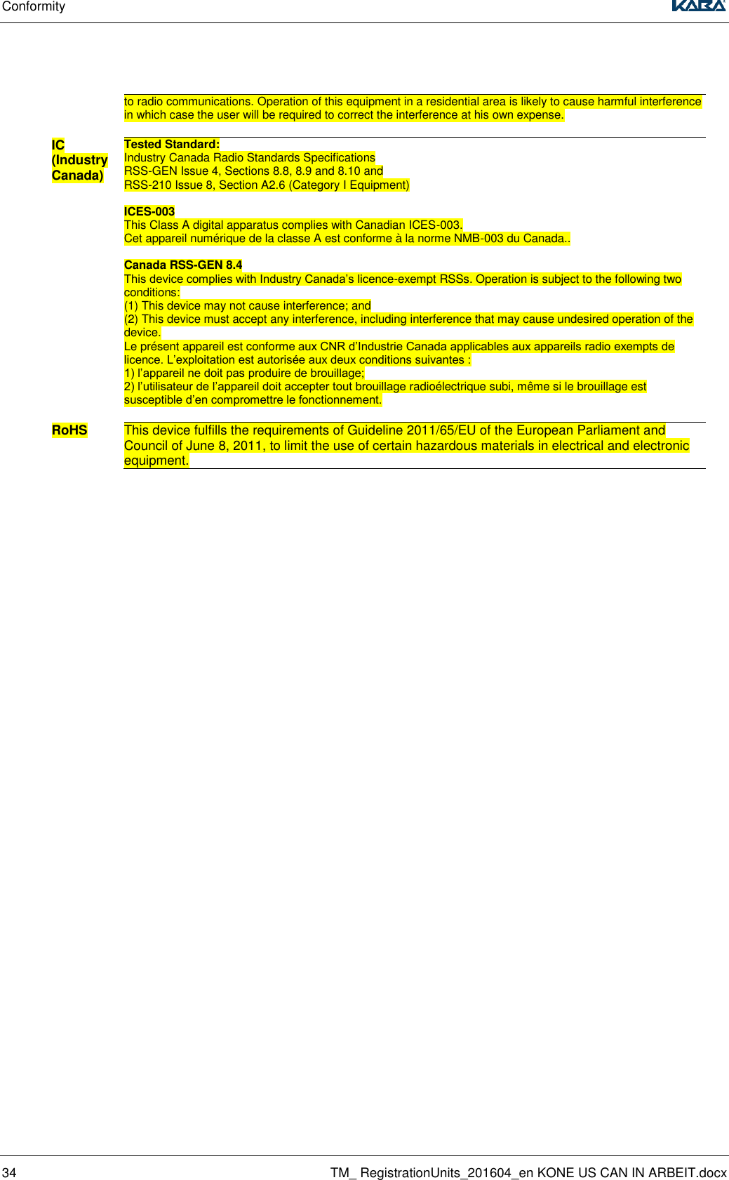
![Conformity 30 TM_ RegistrationUnits_201604_en KONE US CAN IN ARBEIT.docx 8 Conformity 8.1 FCC- and IC- tested registration units FCC- and IC- tested registration units FCC IC Kone regsitration unit PCB Tested Standard: FCC Code of Federal Regulations, CFR 47, Part 15, Sections 15.205, 15.207, 15.215 and 15.225 Tested Standard: Industry Canada Radio Standards Specifications RSS-GEN Issue 4, Sections 8.8, 8.9 and 8.10 and RSS-210 Issue 8, Section A2.6 (Category I Equipment) Kaba registration unit 90 00 Kaba registration unit 90 01 / Kone registration unit 90 01 Kaba registration unit 90 02 / Kone registration unit 90 02 8.2 Conformity Kone Registration Unit PCB The registration unit conforms to the following standards: EN 60950-1:2006/A2:2013 Notice: The device may only be supplied with SELV (Safety Extra Low Voltage) and LPS (Limited Power Source), according to IEC/UL/CSA 60950-1. UL 60950-1:2007/R:2014-10 CAN/CSA-C22.2 No. 60950-1:2007/A2:2014-10 EN 300 330-1 V1.7.1 EN 300 330-2 V1.5.1 In accordance with the provisions of EC directive: 1999/5/EG Radio and Telecommunications Terminal Equipment Directive (R&TTE). FCC Tested Standard: FCC Code of Federal Regulations, CFR 47, Part 15, Sections 15.205, 15.207, 15.215 and 15.225 FCC § 15.19 This device complies with Part 15 of the FCC rules. Operation is subject to the following two conditions: (1) This device may not cause harmful interference, and (2) this device must accept any interference received, including interference that may cause undesired operation. . FCC § 15.21 (Warning Statement) [Any] changes or modifications not expressly approved by the party responsible for compliance could void the user’s authority to operate the equipment. FCC § 15.105 Note: This equipment has been tested and found to comply with the limits for a Class A digital device, pursuant to part 15 of the FCC Rules. These limits are designed to provide reasonable protection against harmful interference when the equipment is operated in a commercial environment. This equipment generates, uses, and can radiate radio frequency energy and, if not installed and used in accordance with the instruction manual, may cause harmful interference to radio communications. Operation of this equipment in a residential area is likely to cause harmful interference in which case the user will be required to correct the interference at his own expense.. IC (Industry Canada) Tested Standard: Industry Canada Radio Standards Specifications RSS-GEN Issue 4, Sections 8.8, 8.9 and 8.10 and RSS-210 Issue 8, Section A2.6 (Category I Equipment)](https://usermanual.wiki/Kaba/KAM9200-K5/User-Guide-3135550-Page-30.png)
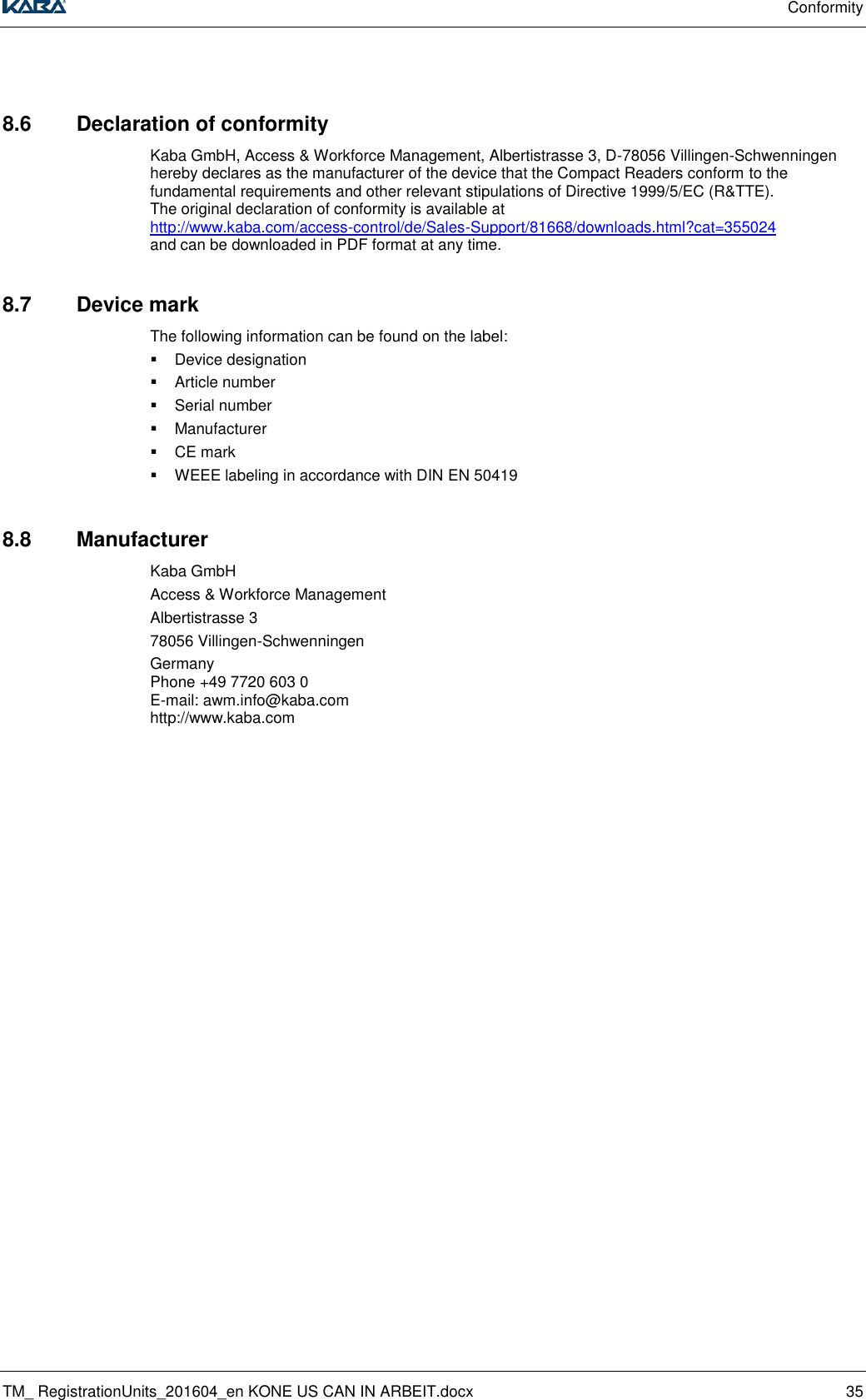
![Conformity TM_ RegistrationUnits_201604_en KONE US CAN IN ARBEIT.docx 31 ICES-003 This Class A digital apparatus complies with Canadian ICES-003. Cet appareil numérique de la classe A est conforme à la norme NMB-003 du Canada. Canada RSS-GEN 8.4 This device complies with Industry Canada’s licence-exempt RSSs. Operation is subject to the following two conditions: (1) This device may not cause interference; and (2) This device must accept any interference, including interference that may cause undesired operation of the device. Le présent appareil est conforme aux CNR d’Industrie Canada applicables aux appareils radio exempts de licence. L’exploitation est autorisée aux deux conditions suivantes : 1) l’appareil ne doit pas produire de brouillage; 2) l’utilisateur de l’appareil doit accepter tout brouillage radioélectrique subi, même si le brouillage est susceptible d’en compromettre le fonctionnement. RoHS This device fulfills the requirements of Guideline 2011/65/EU of the European Parliament and Council of June 8, 2011, to limit the use of certain hazardous materials in electrical and electronic equipment. 8.3 Conformity Kaba Registration Unit 90 00 The registration unit conforms to the following standards: EN 60950-1:2006/A2:2013 Notice: The device may only be supplied with SELV (Safety Extra Low Voltage) and LPS (Limited Power Source), according to IEC/UL/CSA 60950-1. UL 60950-1:2007/R:2014-10 CAN/CSA-C22.2 No. 60950-1:2007/A2:2014-10 EN 300 330-1 V1.7.1 EN 300 330-2 V1.5.1 In accordance with the provisions of EC directive: 1999/5/EG Radio and Telecommunications Terminal Equipment Directive (R&TTE). FCC Tested Standard: FCC Code of Federal Regulations, CFR 47, Part 15, Sections 15.205, 15.207, 15.215 and 15.225 FCC § 15.19 This device complies with Part 15 of the FCC rules. Operation is subject to the following two conditions: (1) This device may not cause harmful interference, and (2) this device must accept any interference received, including interference that may cause undesired operation. FCC § 15.21 (Warning Statement) [Any] changes or modifications not expressly approved by the party responsible for compliance could void the user’s authority to operate the equipment. FCC § 15.105 Note: This equipment has been tested and found to comply with the limits for a Class A digital device, pursuant to part 15 of the FCC Rules. These limits are designed to provide reasonable protection against harmful interference when the equipment is operated in a commercial environment. This equipment generates, uses, and can radiate radio frequency energy and, if not installed and used in accordance with the instruction manual, may cause harmful interference to radio communications. Operation of this equipment in a residential area is likely to cause harmful interference in which case the user will be required to correct the interference at his own expense.](https://usermanual.wiki/Kaba/KAM9200-K5/User-Guide-3135550-Page-31.png)
![Conformity 32 TM_ RegistrationUnits_201604_en KONE US CAN IN ARBEIT.docx IC (Industry Canada) Tested Standard: Industry Canada Radio Standards Specifications RSS-GEN Issue 4, Sections 8.8, 8.9 and 8.10 and RSS-210 Issue 8, Section A2.6 (Category I Equipment) ICES-003 This Class A digital apparatus complies with Canadian ICES-003. Cet appareil numérique de la classe A est conforme à la norme NMB-003 du Canada. Canada RSS-GEN 8.4 This device complies with Industry Canada’s licence-exempt RSSs. Operation is subject to the following two conditions: (1) This device may not cause interference; and (2) This device must accept any interference, including interference that may cause undesired operation of the device. Le présent appareil est conforme aux CNR d’Industrie Canada applicables aux appareils radio exempts de licence. L’exploitation est autorisée aux deux conditions suivantes : 1) l’appareil ne doit pas produire de brouillage; 2) l’utilisateur de l’appareil doit accepter tout brouillage radioélectrique subi, même si le brouillage est susceptible d’en compromettre le fonctionnement. RoHS This device fulfills the requirements of Guideline 2011/65/EU of the European Parliament and Council of June 8, 2011, to limit the use of certain hazardous materials in electrical and electronic equipment. 8.4 Conformity Kaba Registration Unit 90 01 / Kone Registration Unit 90 01 The registration unit conforms to the following standards: EN 60950-1:2006/A2:2013 Notice: The device may only be supplied with SELV (Safety Extra Low Voltage) and LPS (Limited Power Source), according to IEC/UL/CSA 60950-1. UL 60950-1:2007/R:2014-10 CAN/CSA-C22.2 No. 60950-1:2007/A2:2014-10 EN 300 330-1 V1.7.1 EN 300 330-2 V1.5.1 In accordance with the provisions of EC directive: 1999/5/EG Radio and Telecommunications Terminal Equipment Directive (R&TTE). FCC Tested Standard: FCC Code of Federal Regulations, CFR 47, Part 15, Sections 15.205, 15.207, 15.215 and 15.225 FCC § 15.19 This device complies with Part 15 of the FCC rules. Operation is subject to the following two conditions: (1) This device may not cause harmful interference, and (2) this device must accept any interference received, including interference that may cause undesired operation. FCC § 15.21 (Warning Statement) [Any] changes or modifications not expressly approved by the party responsible for compliance could void the user’s authority to operate the equipment. FCC § 15.105 Note: This equipment has been tested and found to comply with the limits for a Class A digital device, pursuant to part 15 of the FCC Rules. These limits are designed to provide reasonable protection against harmful interference when the equipment is operated in a commercial environment. This equipment generates, uses, and can radiate radio frequency energy and, if not installed and used in accordance with the instruction manual, may cause harmful interference](https://usermanual.wiki/Kaba/KAM9200-K5/User-Guide-3135550-Page-32.png)
![Conformity TM_ RegistrationUnits_201604_en KONE US CAN IN ARBEIT.docx 33 to radio communications. Operation of this equipment in a residential area is likely to cause harmful interference in which case the user will be required to correct the interference at his own expense. IC (Industry Canada) Tested Standard: Industry Canada Radio Standards Specifications RSS-GEN Issue 4, Sections 8.8, 8.9 and 8.10 and RSS-210 Issue 8, Section A2.6 (Category I Equipment) ICES-003 This Class A digital apparatus complies with Canadian ICES-003. Cet appareil numérique de la classe A est conforme à la norme NMB-003 du Canada. Canada RSS-GEN 8.4 This device complies with Industry Canada’s licence-exempt RSSs. Operation is subject to the following two conditions: (1) This device may not cause interference; and (2) This device must accept any interference, including interference that may cause undesired operation of the device. Le présent appareil est conforme aux CNR d’Industrie Canada applicables aux appareils radio exempts de licence. L’exploitation est autorisée aux deux conditions suivantes : 1) l’appareil ne doit pas produire de brouillage; 2) l’utilisateur de l’appareil doit accepter tout brouillage radioélectrique subi, même si le brouillage est susceptible d’en compromettre le fonctionnement. RoHS This device fulfills the requirements of Guideline 2011/65/EU of the European Parliament and Council of June 8, 2011, to limit the use of certain hazardous materials in electrical and electronic equipment. 8.5 Conformity Kaba Registration Unit 90 02 / Kone Registration Unit 90 02 The registration unit conforms to the following standards: EN 60950-1:2006/A2:2013 Notice: The device may only be supplied with SELV (Safety Extra Low Voltage) and LPS (Limited Power Source), according to IEC/UL/CSA 60950-1. UL 60950-1:2007/R:2014-10 CAN/CSA-C22.2 No. 60950-1:2007/A2:2014-10 EN 300 330-1 V1.7.1 EN 300 330-2 V1.5.1 In accordance with the provisions of EC directive: 1999/5/EG Radio and Telecommunications Terminal Equipment Directive (R&TTE). FCC Tested Standard: FCC Code of Federal Regulations, CFR 47, Part 15, Sections 15.205, 15.207, 15.215 and 15.225 FCC § 15.19 This device complies with Part 15 of the FCC rules. Operation is subject to the following two conditions: (1) This device may not cause harmful interference, and (2) this device must accept any interference received, including interference that may cause undesired operation. FCC § 15.21 (Warning Statement) Any] changes or modifications not expressly approved by the party responsible for compliance could void the user’s authority to operate the equipment. FCC § 15.105 Note: This equipment has been tested and found to comply with the limits for a Class A digital device, pursuant to part 15 of the FCC Rules. These limits are designed to provide reasonable protection against harmful interference when the equipment is operated in a commercial environment. This equipment generates, uses, and can radiate radio frequency energy and, if not installed and used in accordance with the instruction manual, may cause harmful interference](https://usermanual.wiki/Kaba/KAM9200-K5/User-Guide-3135550-Page-33.png)