Kaba KAM9200-K5 Desktop Reader User Manual Configuration Manual
Kaba GmbH Desktop Reader Configuration Manual
Kaba >
user manual
Registration units
(US/CAN)
Technical Manual
04/2016
TM_ RegistrationUnits_201604_en KONE US CAN IN ARBEIT.docx
EN

Kaba AG
Access & Workforce Management
Hofwisenstrasse 24
8153 Rümlang
Switzerland
Phone +41 44 818 93 11
www.kaba.com
Kaba AG
Access & Workforce Management
Mühlebühlstrasse 23
8620 Wetzikon
Switzerland
Phone +41 44 931 61 11
www.kaba.com
Kaba GmbH
Access & Workforce Management
Albertistrasse 3
78056 Villingen-Schwenningen
Germany
Phone +49 7720 603 0
www.kaba.com
This document must not be reproduced in any way or otherwise further used without the written consent of Kaba AG.
All product names are trademarks of the respective companies.
Copyright 2016 Kaba AG. All rights reserved.
Publication: 04/2016
TM_ RegistrationUnits_201604_en KONE US CAN IN ARBEIT.docx

TM_ RegistrationUnits_201604_en KONE US CAN IN ARBEIT.docx 3
1 About this Document ............................................................................... 5
1.1 Validity ........................................................................................................ 5
1.2 Target Group .............................................................................................. 5
1.3 Supplementary Documents ........................................................................ 6
1.4 Change Protocol ........................................................................................ 6
1.5 Abbreviations.............................................................................................. 7
1.6 Danger categories ...................................................................................... 7
2 Basic safety information .......................................................................... 8
2.1 Intended usage .......................................................................................... 8
2.2 Service and maintenance ........................................................................... 8
2.2.1 ESD protective measures .......................................................................... 8
2.2.2 Environmental Hazards .............................................................................. 8
3 General Rules and Information ................................................................ 9
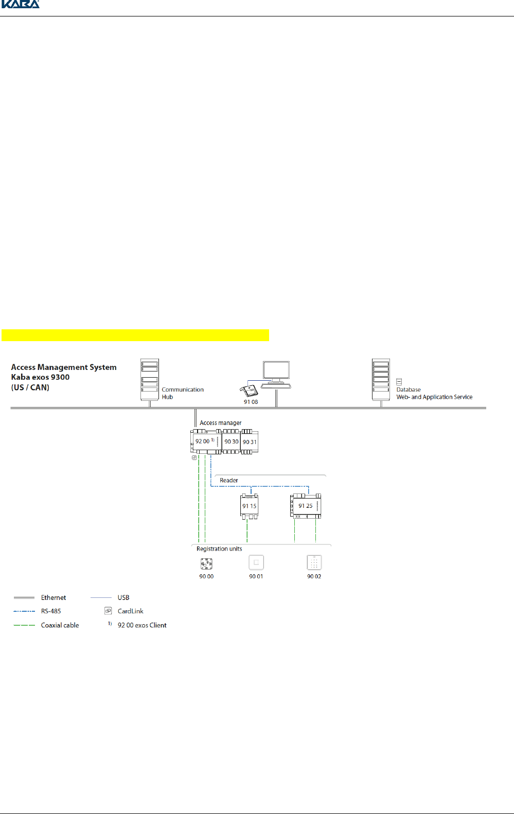
3.1 Topologies .................................................................................................. 9
3.1.1 Access Management System MIFARE / LEGIC ........................................ 9
3.1.2 Replacing Kaba exos LT-PN with Registration Unit 90 02 ...................... 10
3.1.3 B-COMM .................................................................................................. 11
3.1.4 Standalone Mode ..................................................................................... 11
3.2 Hardware Compatibility ............................................................................ 12
3.2.1 Registration Unit Compatibility ................................................................. 12
3.3 Supported RFID Standards ...................................................................... 12
3.4 Reading and Writing Properties ............................................................... 13
3.4.1 Basic Technical Relationships ................................................................. 13
3.4.2 Reading and Writing Distances ................................................................ 13
3.5 Mounting and Installation Information ...................................................... 14
3.5.1 Concealed Cable Mounting ...................................................................... 14
3.5.2 Antenna Cable to the Registration Units .................................................. 14
3.5.3 Coaxial Cable Terminal ............................................................................ 14
3.5.4 Distance between Antennae .................................................................... 14
3.5.5 Antenna Distance - Metal Bodies ............................................................. 15
3.6 Display and Signal Elements ................................................................... 15
4 Kaba registration unit 90 01 / Kone registration unit 90 01 ............... 16
4.1 Product description .................................................................................. 16
4.2 Dimension drawing ................................................................................... 16
4.3 Installation ................................................................................................ 17
4.3.1 Preparation ............................................................................................... 17
4.4 Connection ............................................................................................... 18
4.4.1 Connection with quickwireTM Technology ................................................. 18
4.4.2 Connecting the Coaxial Cable .................................................................. 18
4.5 Typical Maximum Reading Distance ........................................................ 18
4.5.1 Reading and Writing Distance with Direct Mounting on Metal ................. 18
4.6 Technical Data ......................................................................................... 19
4.7 Dismantling ............................................................................................... 20
4.7.1 Accessories .............................................................................................. 20
4.8 Conformity ................................................................................................ 20

4 TM_ RegistrationUnits_201604_en KONE US CAN IN ARBEIT.docx
5 Kaba Registration 90 02 / Kone Registration 90 02 .............................. 21
5.1 Product description ...................................................................................21
5.2 Dimensions ...............................................................................................21
5.3 Installation ................................................................................................21
5.3.1 Preparation ...............................................................................................21
5.4 Connection ...............................................................................................22
5.4.1 Connection with quickwireTM Technology .................................................22
5.4.2 Connecting the Coaxial Cable ..................................................................22
5.4.3 Operation of the keypad ...........................................................................24
5.5 Typical Maximum Reading Distance ........................................................24
5.5.1 Reading and Writing Distance with Direct Mounting on Metal .................24
5.6 Technical Data .........................................................................................25
5.7 Dismantling ...............................................................................................26
5.7.1 Accessories ..............................................................................................26
5.8 Conformity ................................................................................................26
6 Kaba Registration 90 00 / Kone registration unit PCB .......................... 27
6.1 Product description ...................................................................................27
6.2 Mounting and Connection ........................................................................27
6.2.1 Mounting and Connection ........................................................................27
Connecting the Coaxial Cable .................................................................................27
6.2.2 LED...........................................................................................................27
6.3 Typical Maximum Reading Distance ........................................................28
6.3.1 Reading and Writing Distance with Direct Mounting on Metal .................28
6.4 Technical Data .........................................................................................28
6.4.1 Accessories ..............................................................................................28
6.5 Conformity ................................................................................................28
7 Dismantling and disposal ....................................................................... 29
7.1 Dismantling / Put out of operation ............................................................29
7.2 Disposal ....................................................................................................29
7.2.1 Disposing of packaging ............................................................................29
7.2.2 Disposing of the device ............................................................................29
8 Conformity ............................................................................................... 30
8.1 FCC- and IC- tested registration units ......................................................30
8.2 Conformity Kone Registration Unit PCB ..................................................30
8.3 Conformity Kaba Registration Unit 90 00 .................................................31
8.4 Conformity Kaba Registration Unit 90 01 / Kone Registration Unit 90 0132
8.5 Conformity Kaba Registration Unit 90 02 / Kone Registration Unit 90 0233
8.6 Declaration of conformity .........................................................................35
8.7 Device mark .............................................................................................35
8.8 Manufacturer ............................................................................................35
TM_ RegistrationUnits_201604_en KONE US CAN IN ARBEIT.docx 5
1 About this Document
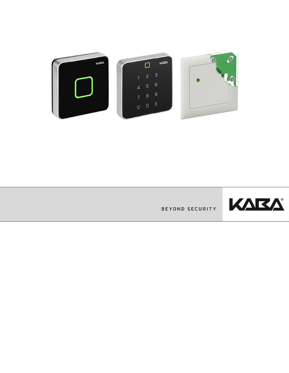
The following registration units can be used in a range of Kaba system solutions (Kaba exos,
B-COMM, KEM):
Product name until 2014/06/30
Product from 2014/07/01
Registration unit RFID
Registration unit RFID PIN
Registration unit Print RFID
Kaba registration unit 90 01
Kone registration unit 90 01
Kaba registration unit 90 02
Kone registration unit 90 02
Kaba registration unit 90 00
Kone registration unit PCB
This document describes the mounting and installation of registration units. The instructions should be
followed consistently to ensure fault-free and safe application.
All drawing dimensions in millimeters (mm).
1.1 Validity
Compatibility between registration units and control units (reading devices) is described in Chapter
3.2.1 on page 12.
1.2 Target Group
This manual is only intended for specialist personnel.
The descriptions require personnel trained by the manufacturer.
The descriptions do not replace product training.
A service person is a person who has appropriate technical training and experience, which is required
in order to be aware of the risks which they or other people are exposed to when carrying out this work
as well as to keep the risks for themselves and other people as low as possible. It is the responsibility
of the service person to ensure compliance with the conditions stated by the manufacturer, as well as
applicable regulations and standards, when conducting this work.
This document is also used for information for people undertaking the following work:
Project planning and project implementation
Commissioning of the product within the network
Connection of the product to the user software by programming customer applications
Customer specific adjustment via parameterization of the product
NOTICE
For reasons of device safety, the actions described in this document for installation, maintenance and
servicing may only be carried out by a service person in accordance with EN 60950-1 (Information
Technology Equipment – Safety).
About this Document
6 TM_ RegistrationUnits_201604_en KONE US CAN IN ARBEIT.docx
1.3 Supplementary Documents
Document name until
2014/06/30
Document name
from 2014/07/01
Contents
Availability
TM_AccessManagerMIFARE_V0x
TM_AccessManager9200
Kaba Access Manager 92 00 -
Technical Manual
http://ftp.kaba.com/ExosDow
nload
partly on Kaba Portal AC
TM_RemoteReaderMIFARE_V0x
TM_ RemoteReader9115
Remote Reader 91 15 -
Technical Manual
PGL_Thema Kaba exos 9300
PGL_Thema
Kaba exos 9300
Planning Guidelines, according
to subject, e.g., hardware
Kaba exos iDML2 Technical
Documentation
Kaba exos DML2 Technical
Documentation
1.4 Change Protocol
The most important changes to the last edition of this manual are listed below:
Version Number
Edition
Brief Description
V01
12/2010
First edition
V02
01/2011
Various adjustments
V03
12/2011
Abbreviations chapter
Topologies chapter supplement with Replacing
Kaba exos LT-PN with Registration Unit RFID PIN and
B-COMM
Hardware Compatibility chapter
Supported RFID Standards chapter
New chapter: Distance between Antennae
Text and graphics: Typical Maximum Reading Distances with
registration units
New chapter: egistration unit LA-PP
New chapter: Bolt Handle for IT Cabinets
Registration Units – Conformity chapter
V04
01/2014
Integration of registration unit 90 04
Various adjustments and additions
201406
06/2014
New product names
New file names
201604
04/2016
Additional FCC / IC sentences
List of supported registration units
About this Document
TM_ RegistrationUnits_201604_en KONE US CAN IN ARBEIT.docx 7
1.5 Abbreviations
Abbreviation
Term name until 2014/06/30
Term from 2014/07/01
Host
Host system
Host system
Control unit
Fehler! Keine gültige
Verknüpfung.
Access manager, terminal or
Kaba exos AMC/-II
Remote Reader
Remote Reader MIFARE (RR-M)
or
Remote Reader LEGIC (RR-L)
Kaba remote reader 91 15
Access Manager
Access Manager MIFARE (AM-
M), or Access Manager LEGIC
(AM-L)
Kaba access manager 92 00
Registration unit
Registration unit RFID
Registration unit RFID PIN
Registration unit Print RFID
Kaba registration unit 90 01
Kone registration unit 90 01
Kaba registration unit 90 02
Kone registration unit 90 02
Kaba registration unit 90 00
Kone registration unit PCB
Antennas
Registration units
Registration units
1.6 Danger categories
Notes containing information, requirements, and prohibitions are clearly marked to help prevent injury
to personnel and damage to equipment.
Observe these danger warnings. They are intended to help prevent accidents and avoid damage.
Danger warnings are categorized as follows:
NOTICE
Important information regarding proper handling of the product.
Failure to observe this information may lead to malfunctions and may cause the device or other items
in its vicinity to be damaged.
Notes
Please pay particular attention to the warnings marked with symbols.
User tips and useful information which help to utilize the product and its functions to their full potential.
Basic safety information
8 TM_ RegistrationUnits_201604_en KONE US CAN IN ARBEIT.docx
2 Basic safety information
The devices are constructed in accordance with the state of the art and recognized safety rules.
Despite this, handling this product may present sources of danger for persons and valuables.
Read and observe the following safety information before you use the product.
2.1 Intended usage
The devices and system are only intended to be used as outlined in the chapter Product description.
Any type of usage beyond the scope of this is not considered to be intended usage. The manufacturer
shall accept no liability for damage resulting from this unintended usage. The user/operator alone shall
bear the associated risk.
Only service persons may carry out the mounting and installation of a device; see Chapter 1.2, page 5.
Installation may only be carried out at locations that fulfill the climatic and technical conditions specified
by the manufacturer.
Kaba GmbH shall not accept liability for any damage that occurs as a result of improper handling or
incorrect installation.
2.2 Service and maintenance
Maintenance work/Correcting faults
Troubleshooting and maintenance work must only be performed by a service person; see Chapter 1.2,
page 5.
Modifications and alterations
Conversions and modifications of the device must only be performed by a service person; see
Chapter 1.2, page 5. Any conversions and modifications performed by other persons will result in a
complete exclusion of liability. Any modifications and alterations carried out by other persons will lead
to total exclusion of liability.
2.2.1 ESD protective measures
NOTICE
Danger to electronic components due to electrostatic discharge.
Improper handling of electronic PCBs or components may lead to damage that causes total failure or
sporadic errors.
General ESD protective measures must be observed when installing and repairing the device
The following rules must be observed:
Wear an ESD grounding armband when handling electronic components
Connect the end of the armband to a discharge socket or an unpainted, grounded metal
component. This will discharge static loads safely and effectively from your body
Only handle PCBs by their edges. Do not touch PCBs or connectors
Place any removed components on an antistatic surface or in an antistatic shielded container
Avoid contact between PCBs and articles of clothing. The armband only protects the PCBs against
electrostatic discharge voltage on the body; damage may still result from electrostatic discharge on
clothing
Only use electrostatically shielding and conductive protective bags to transport and ship modules
that have been removed
2.2.2 Environmental Hazards
See Chapter 7.2, page 29
General Rules and Information
TM_ RegistrationUnits_201604_en KONE US CAN IN ARBEIT.docx 9
3 General Rules and Information
The registration units can be used in a wide range of Kaba system solutions (Kaba exos, B-COMM,
KEM).
3.1 Topologies
The separation of the registration units from the control unit facilitates various antenna designs. With
the help of suitable housing, the antennae can be adjusted to the spatial and security-related
requirements of a building.
The registration units 90 02 is used for entering the personal PIN code. It is therefore particularly
suitable for external access or installations with increased security requirements. It can be retro-fitted at
any time with no or minimal wiring changes.
The different antenna variants allow different RFID reading-writing distances to be achieved. The
properties also result from local events and the identification medium used.
Tampering Security
The registration units are separate from the hardware (reading devices). Regardless of the mounting
location, the associated control unit can be installed in a tamper-proof room.
Manipulation Security
The communication between registration unit and associated control unit is encrypted and therefore
offers optimal security.
3.1.1 Access Management System MIFARE / LEGIC
General Rules and Information
10 TM_ RegistrationUnits_201604_en KONE US CAN IN ARBEIT.docx
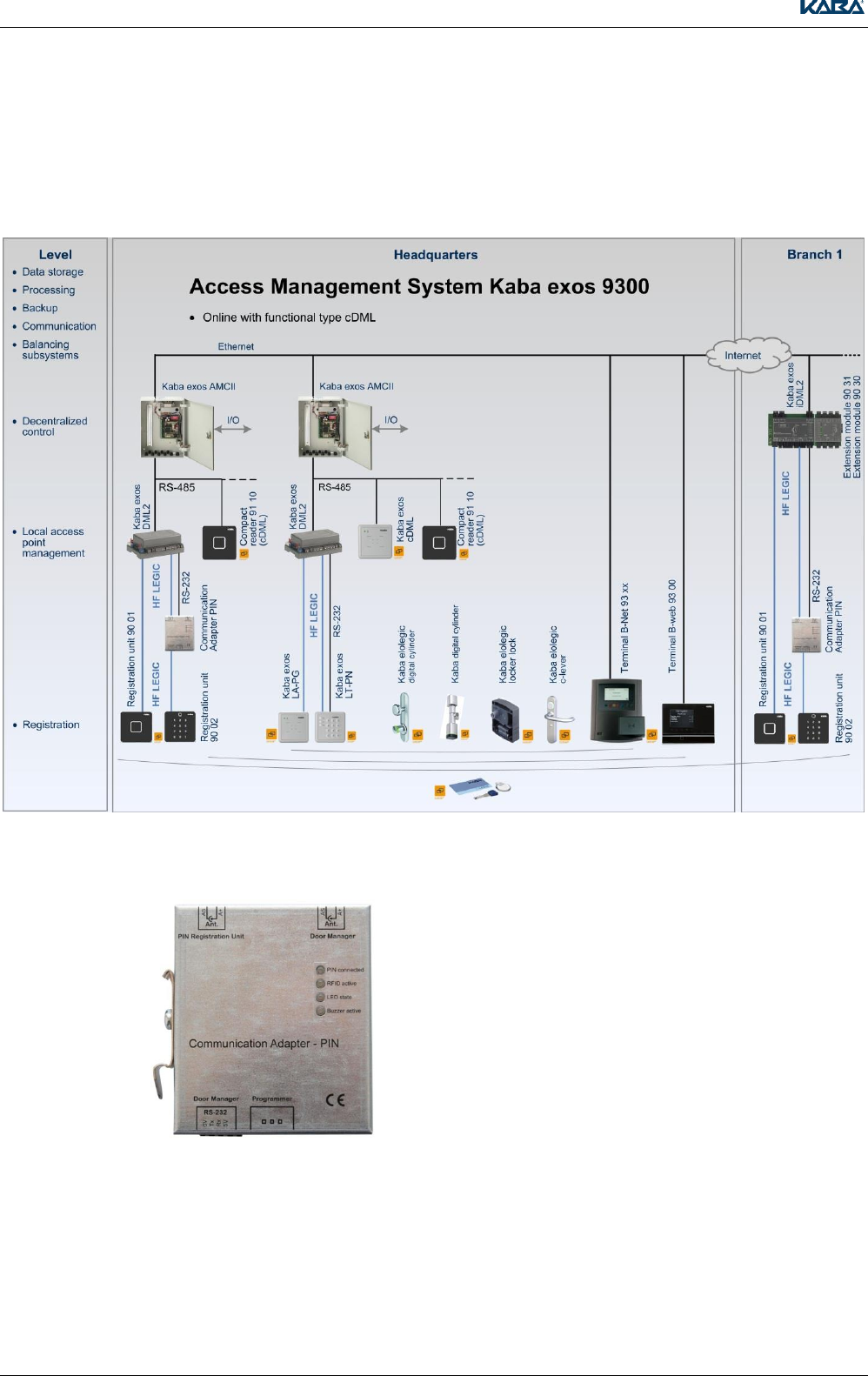
3.1.2 Replacing Kaba exos LT-PN with Registration Unit 90 02
The Communication Adapter PIN allows the registration units 90 02 to be integrated into existing or
new LEGIC customer sites. The communication adapter PIN enables connection of the
registration units 90 02 to the door managers Kaba exos DML2 and Kaba exos LS-110 and to the
Access Manager Kaba exos iDML2.
Illustration of Communication Adapter PIN
Detailed information on the mounting and connection of the Communication Adapter PIN can be found
in the supplementary sheet.
General Rules and Information
TM_ RegistrationUnits_201604_en KONE US CAN IN ARBEIT.docx 11
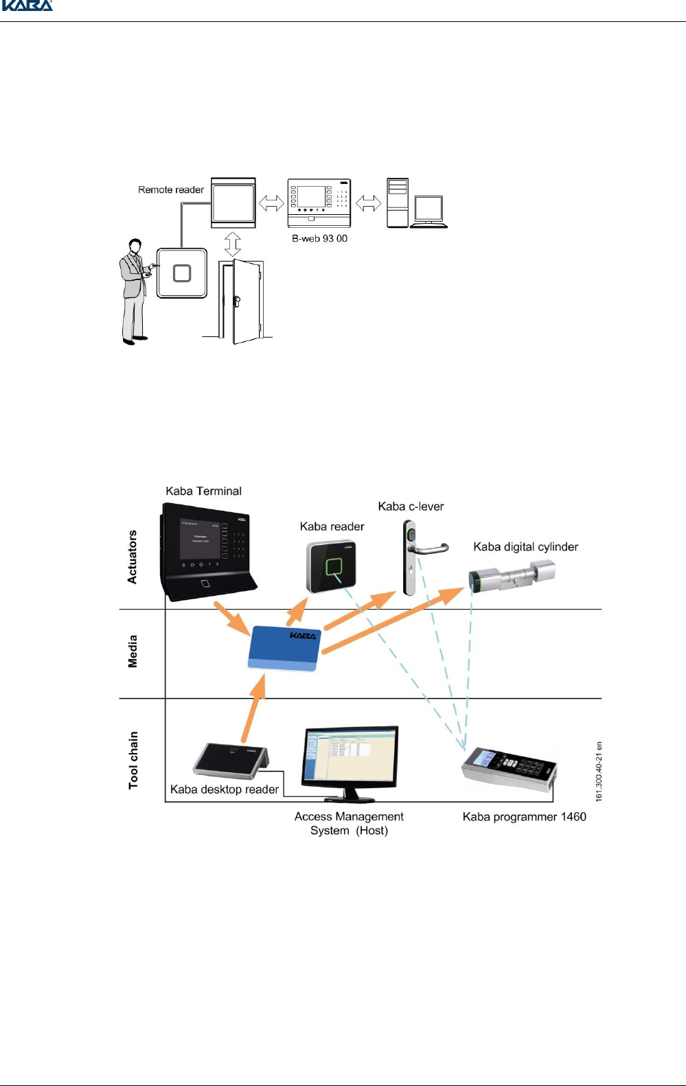
3.1.3 B-COMM
The remote reader works as a subterminal on a B-web series terminal. The data exchange between
remote reader and terminal is performed in half-duplex mode via the RS-485 interface (subpartyline).
Communication is performed via the transfer protocol BPA/9 subset.
3.1.4 Standalone Mode
The required data for the whitelist or CardLink are saved in the remote reader via the
programmer 1460. The authorization check and access control are therefore sensed by the remote
reader.
General Rules and Information
12 TM_ RegistrationUnits_201604_en KONE US CAN IN ARBEIT.docx
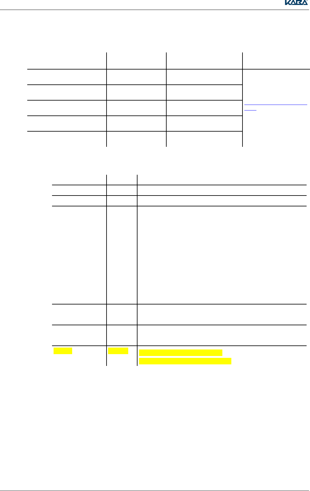
3.2 Hardware Compatibility
3.2.1 Registration Unit Compatibility
Control Unit
Registration unit
Access Manager
Kaba exos iDML2
Remote Reader
Functional type Access Manager
Remote Reader
Functional type Subterminal
Remote Reader
Functional type E300 V4
Kaba exos DML2
Kaba exos LS-110
Kaba elolegic Remote Reader
Registration unit 90 01
Registration unit 90 02
1
--
1
1
--
Registration unit 90 00
1 = only compatible with use of Communication Adapter PIN
3.3 Supported RFID Standards
Depending on the access manager to which the registration unit is connected to, the following
RFID standards are supported:
ISO 14443A MIFARE/LEGIC
LEGIC RF
ISO 15693
General Rules and Information
TM_ RegistrationUnits_201604_en KONE US CAN IN ARBEIT.docx 13
3.4 Reading and Writing Properties
The typical maximum reading distance of a registration units is detailed in the corresponding chapters.
The following planning guidelines (PGL) will help you to select suitable media/compact reader
combinations:
PGL_Media_LEGIC
PGL_Media_MIFARE_ARIOS
PGL_Migration_RFID_Technology_Kabaexos9300
3.4.1 Basic Technical Relationships
The read and write distance fundamentally depends on the size of the registration unit's antenna, the
size of the medium, and the media technology
LEGIC prime, MIFARE classic and ISO15693:
Cards: The read and write distance tends to be slightly greater than the diameter of the registration
unit's antenna
Key fobs and smart keys: The read and write distance tends to be slightly smaller than the diameter
of the registration unit's antenna
LEGIC advant, MIFARE DESFire
The read and write distance is approx. 3/4 of the size of the figures given above.
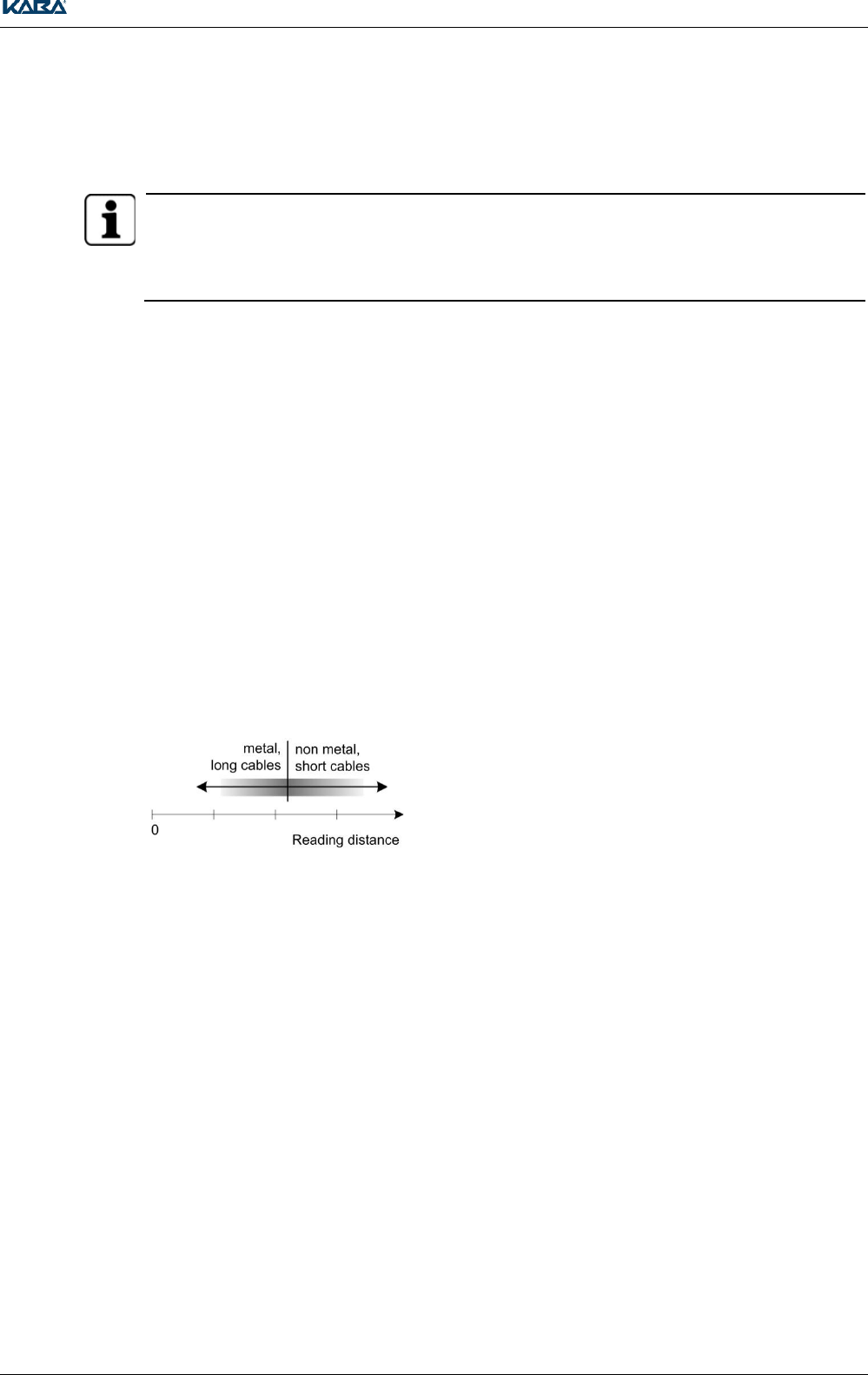
Influence of a Metallic Environment and the Cable Length
A metallic environment reduces the reading and writing distance The read and write properties of
registration unit 90 04 are not impaired by metallic objects in its surroundings.
The shorter the coaxial cable, the better the reading and writing distance
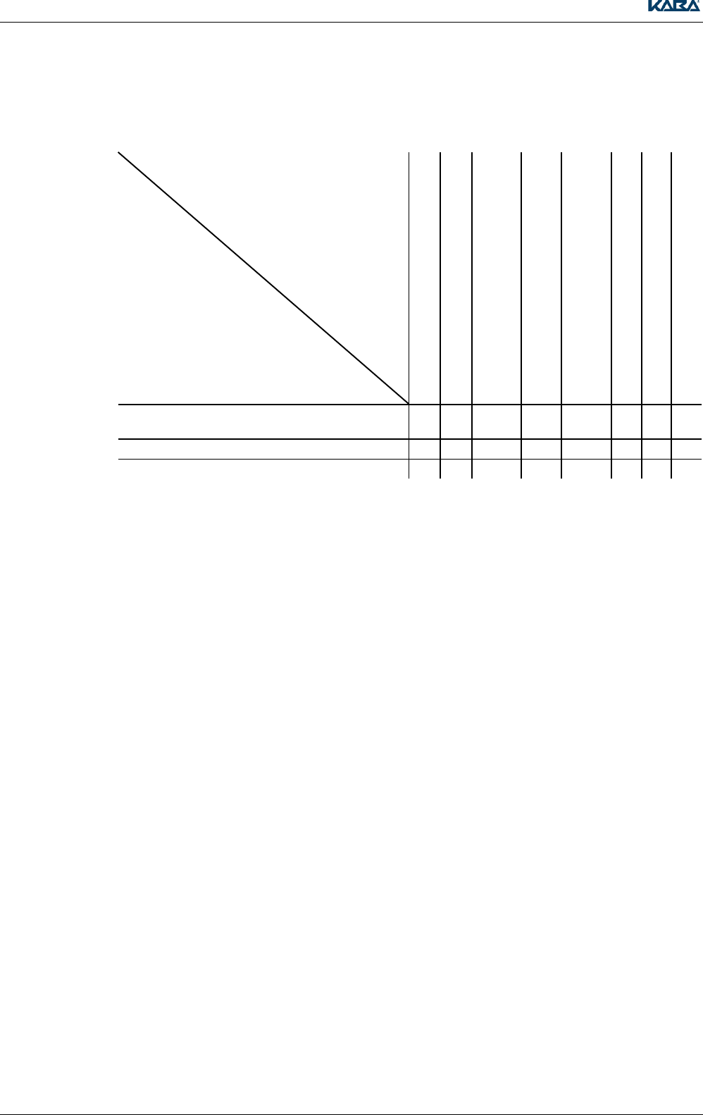
The reading distances in the diagram for the
respective registration units RFID are calculated
average values from:
Metal - non-metal
Cable lengths 1 m to 30 m
(registration unit 90 02: 3 - 30 m)
See Chapter 3.5.4,page Seite 14
3.4.2 Reading and Writing Distances
Information on writing and reading distances can be found on the Kaba Portal Access Management
portal.kaba.biz in the Mechatronics/Kaba evolo/Kaba Media/Instructions tab.
General Rules and Information
14 TM_ RegistrationUnits_201604_en KONE US CAN IN ARBEIT.docx
3.5 Mounting and Installation Information
The mounting and installation of the device may only be carried out by a service person as per DIN EN
60950-1:2006 + A11:2009.
The device must only be installed in locations that fulfill the climatic and technical conditions specified
by the manufacturer.
3.5.1 Concealed Cable Mounting
The registration unit PCB RFID and registration unit LA-PP are screwed onto the switch box for
concealed mounting. The following must be observed when doing so:
There must be sufficient cable in reserve so that no tension is created at the terminal connections. The
reserve cable should not be too long (max. 25 cm) and, where necessary, should be laid in a figure
eight.
3.5.2 Antenna Cable to the Registration Units
The signals of the antenna, LED, buzzer and PIN code keypad are conducted via the coaxial cable.
Cable Type RG 174/U
Coaxial cable 50 Ohm
Recommended: RG 174/U, 50 Ohm, Supplier: Huber + Suhner
Recommended Cable Length
< 10 m
Max. Cable Length
30 m
WARNING
To avoid external interference, the antenna cable must not be laid parallel to power lines or other
sources subject to disturbance
Unnecessary antenna cables should be stored in a figure eight
3.5.3 Coaxial Cable Terminal
The inner conductor and shield of the coaxial cable must not be connected to ground.
The coaxial cable terminal of the registration units is described in the corresponding chapters.
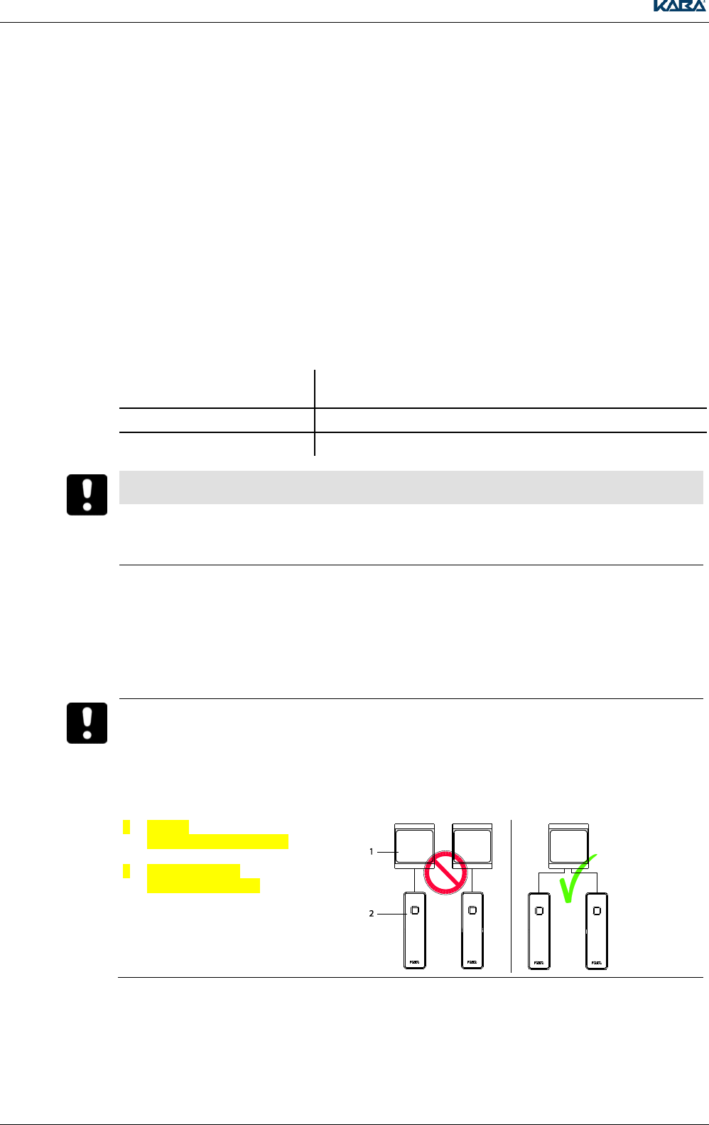
3.5.4 Distance between Antennae
Placing registration units and compact readers close together may reduce the read and write
distances*.
Install registration units and compact readers at a sufficient distance
*
Exception: registration units which are connected to the same reader (e.g. remoter reader 91 15)
1
2
Reader
e.g. remote reader 91 15
Registration unit
e.g. registration unit
General Rules and Information
TM_ RegistrationUnits_201604_en KONE US CAN IN ARBEIT.docx 15
3.5.5 Antenna Distance - Metal Bodies
Influence of the magnetic field in the vicinity of the antenna by a metal body results in shorter reading
distances and can even cause failure of reading functionality. The electro-magnetic field is short-
circuited in the metallic environment.
WARNING
To maximize the antenna when mounting, we recommend surface cable mounting with a spacer
frame
The read/write quality of the antenna should be checked in all cases
Often an air gap in the conductive body is sufficient to weaken the magnetic sufficiently so that the
antenna is no longer materially influenced
3.6 Display and Signal Elements
The registration units are equipped with a two-color, red/green illuminating symbol and a buzzer.
The buzzers provide acoustic signaling of the access decision
The red/green illuminating symbol indicates the operating state and access decision
The keypad lights up brightly when a PIN code input is required
The detailed signaling of all registration units during the different booking processes is described in
the documentation Operation of Registration Units RFID.
Kaba registration unit 90 01 / Kone registration unit 90 01
16 TM_ RegistrationUnits_201604_en KONE US CAN IN ARBEIT.docx
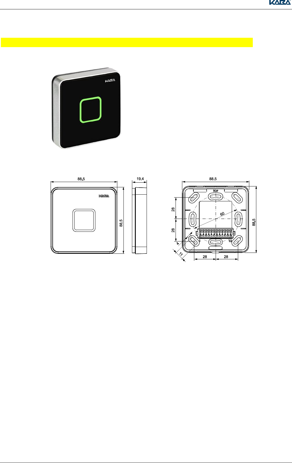
4 Kaba registration unit 90 01 / Kone registration unit 90 01
4.1 Product description
The registration unit 90 01 with integrated
antenna, together with a control unit, represents a
fully-integrated solution for access control with
simultaneous convenient identification of the user.
This registration unit is suitable for both internal
and external applications.
4.2 Dimension drawing
Height incl. rear panel: 19,4 mm
Height spacer frame: 26,4 mm
External dimensions
Dimensions of rear panel/spacer frame
Kaba registration unit 90 01 / Kone registration unit 90 01
TM_ RegistrationUnits_201604_en KONE US CAN IN ARBEIT.docx 17
4.3 Installation
4.3.1 Preparation
If necessary, drill holes for the frame bracket.
A dimension drawing of the frame can be found above.
Surface cable mounting:
Use the spacer frame (only indoors).
Break open the cable inlet on the spacer frame.
Lead the cable away at the bottom or at the side in a siphon shape.
NOTICE
Only connect the wires when the power is switched off.
Procedure
1.
Pull the cable through the rear panel or the spacer frame.
Screw the rear panel or the spacer frame to an even surface.
The rear panel or spacer frame must not lose its shape.
Small bumps can be balanced out using the sealing pad.
Lead the cable away in a siphon shape to prevent the ingress of water.
2.
Connect the cable strands to the connection terminal.
An overview showing the assignment of connection terminals can be found in Chapter 4.4.2
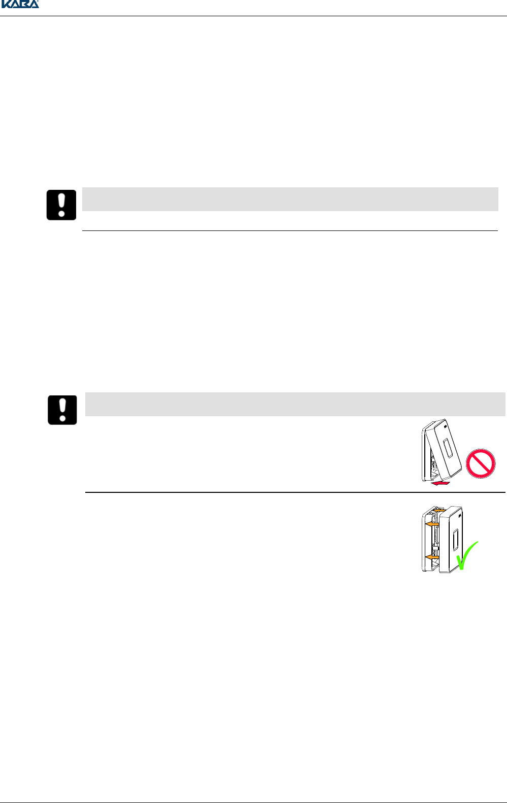
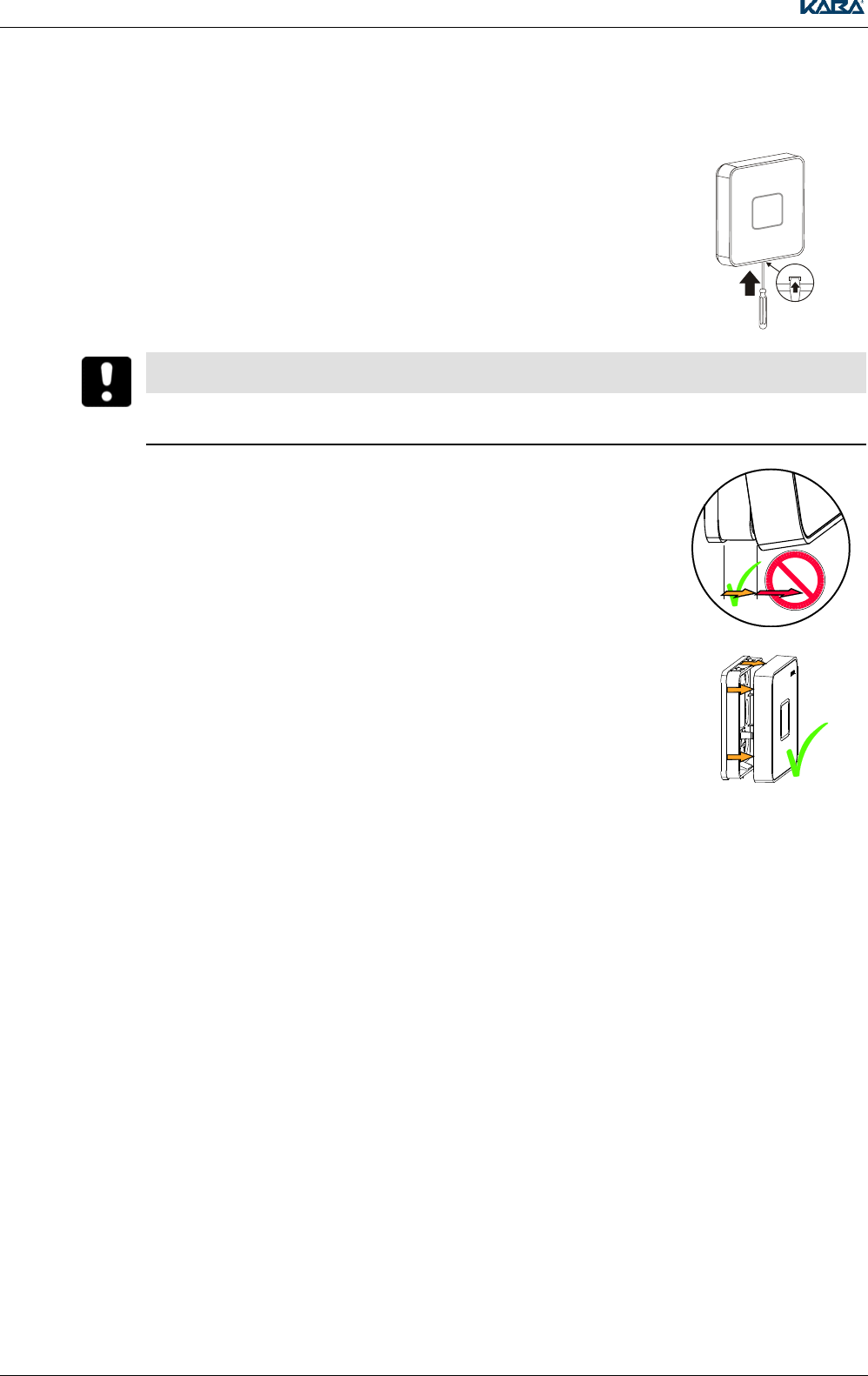
NOTICE
The pin strip can be damaged. Observe the following instructions.
3.
Slide the registration unit in a parallel position over the rear panel or the
spacer frame.
4.
Press the registration unit against the rear panel or the spacer frame until it clicks into position at
both the top and the bottom.
Kaba registration unit 90 01 / Kone registration unit 90 01
18 TM_ RegistrationUnits_201604_en KONE US CAN IN ARBEIT.docx
4.4 Connection
4.4.1 Connection with quickwireTM Technology
With the innovative quickwire technology, the wiring is performed completely separately from the
electronics on the mounting plate (rear panel or spacer frame). The electronics are mounted as a unit
during commissioning. The practical click connection makes mounting simpler and means the
registration unit is quickly changed in case of repair.
In addition, it is possible to upgrade from a registration unit without a PIN to a registration unit with PIN
with no or minimal changes to wiring.
NOTICE
Notice:
The device may only be supplied with SELV (Safety Extra Low Voltage) and LPS (Limited Power Source),
according to IEC/UL/CSA 60950-1.
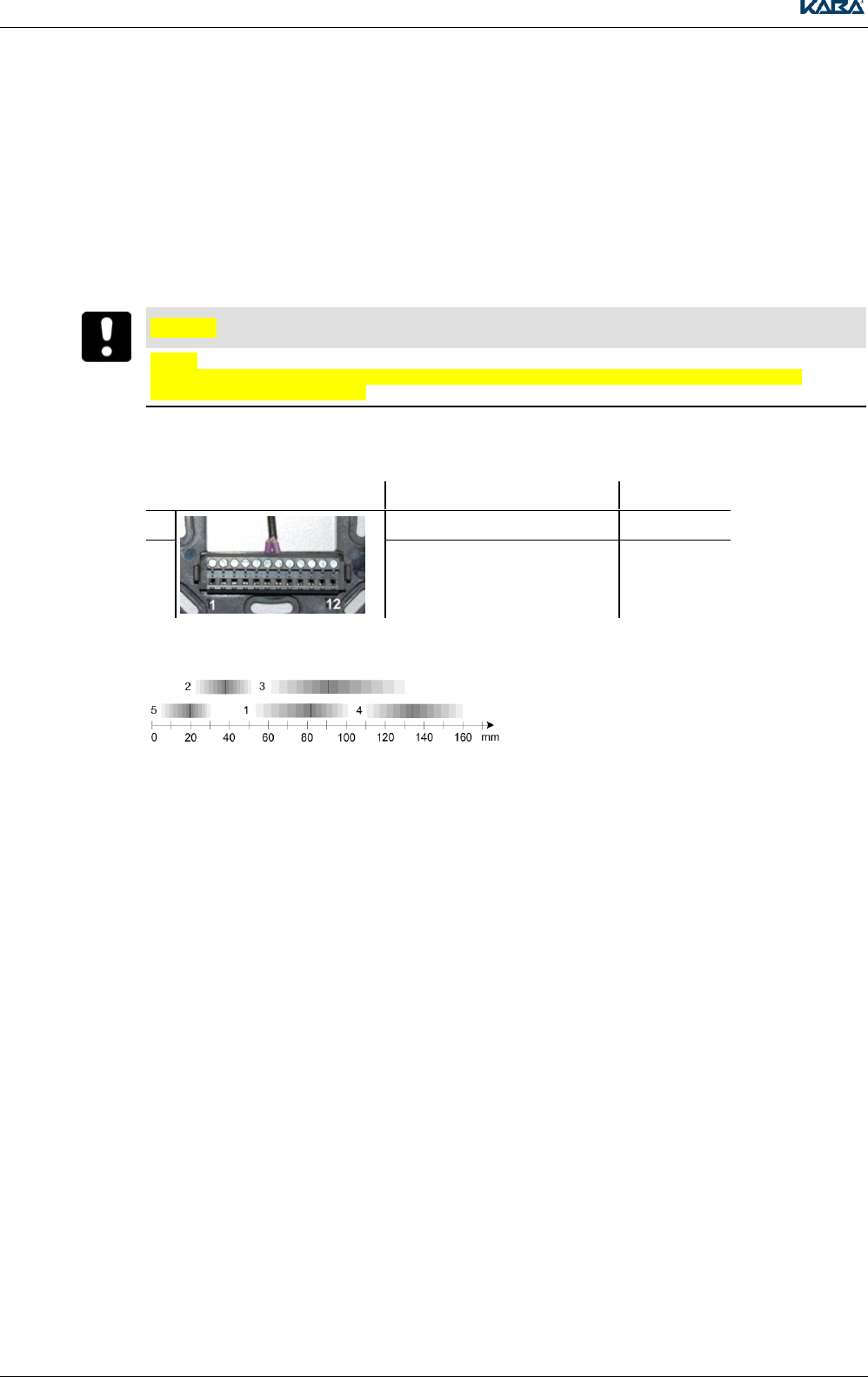
4.4.2 Connecting the Coaxial Cable
Terminal Number
Meaning
Control Unit
6
Antenna cable shield wire
AS
7
Antenna cable inner conductor
A+
4.5 Typical Maximum Reading Distance
1 = Badge, ISO 14443A
2 = Key fob, ISO 14443A
3 = Badge, LEGIC RF
4 = Badge, ISO 15693
5 = Kaba elolegic smart key, LEGIC RF
4.5.1 Reading and Writing Distance with Direct Mounting on Metal
If the registration unit is mounted directly on a metallic surface, the reading and writing distance is
approx. 10% smaller than an RFID neutral environment (wood, masonry).
Kaba registration unit 90 01 / Kone registration unit 90 01
TM_ RegistrationUnits_201604_en KONE US CAN IN ARBEIT.docx 19
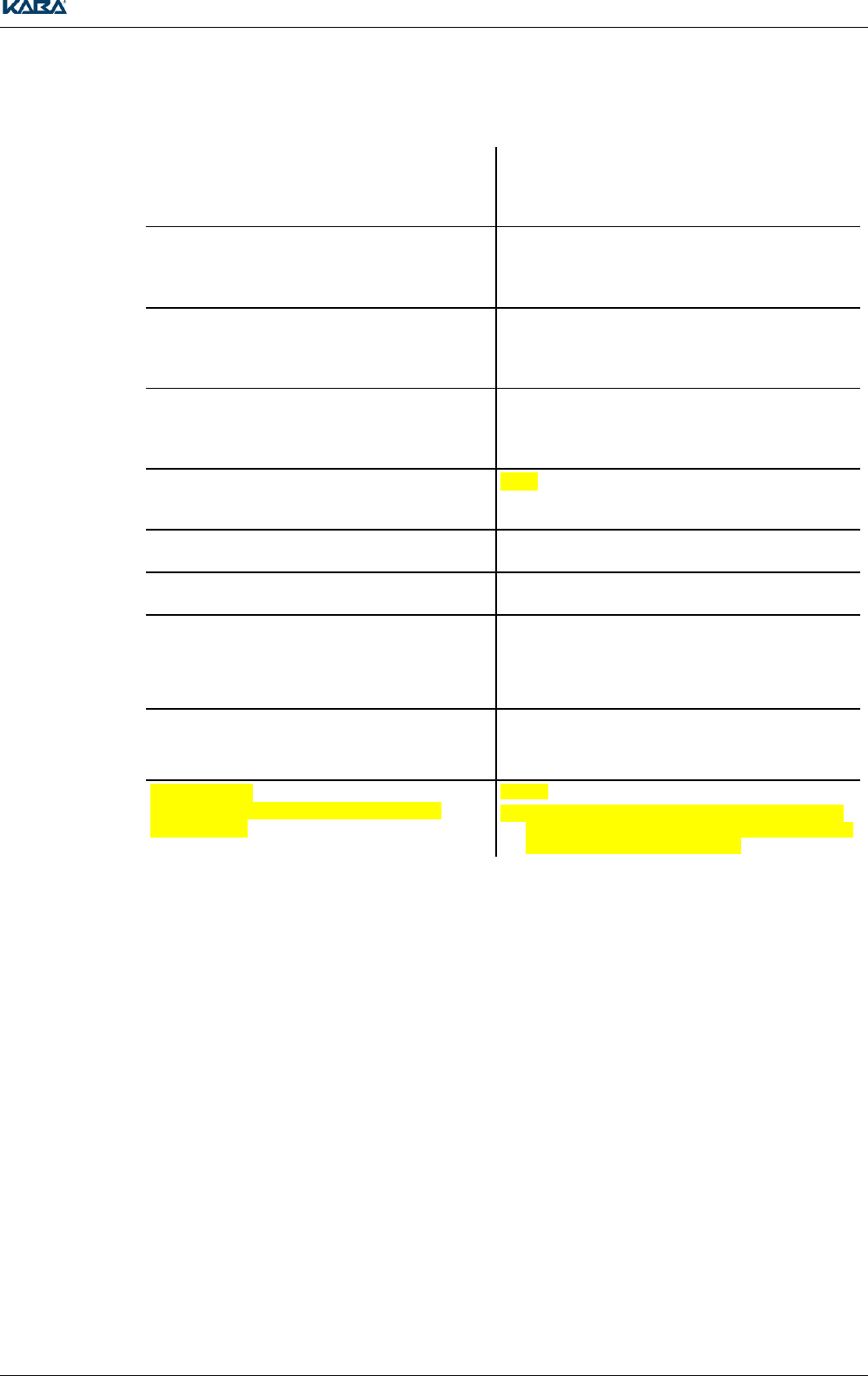
4.6 Technical Data
Spacer Frame / Rear Panel:
Material
PC-ABS
Frame:
Material
PC-ABS
Front:
Material
PMMA back-printed
Dimensions:
With rear panel (concealed cable mounting)
88.5 x 88.5 x 19.4 mm (length x width x height)
With spacer frame (surface cable mounting)
88.5 x 88.5 x 26.4mm (length x width x height)
Protection Type IEC 60529
IP54;
Only with concealed cable mounting and sealing
pad
Temperature Range
- 25° - +70°C (operation)
- 40° - +85°C (storage)
Ambient Conditions
Relative humidity
0% - 95% non condensing
Application
Concealed cable mounting with real panel
Surface cable mounting with spacer frame
Mounting possible directly on metal or neutral
subsurface
Coaxial cable
Recommended: RG 174/U, 50 Ohm
Supplier: Huber + Suhner
max. lenght 30 m
Power supply
The registration unit is powerd by the host
control device
Notice:
The device may only be supplied with SELV (Safety
Extra Low Voltage) and LPS (Limited Power Source),
according to IEC/UL/CSA 60950-1.
Kaba registration unit 90 01 / Kone registration unit 90 01
20 TM_ RegistrationUnits_201604_en KONE US CAN IN ARBEIT.docx
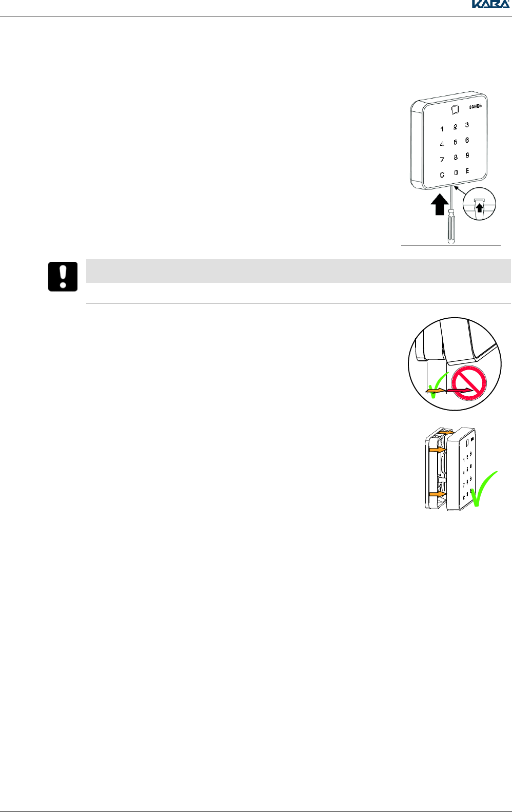
4.7 Dismantling
1. Insert a screwdriver (no. 1) into the bottom of the opening and press it
upwards.
The quick-release lock opens up.
NOTICE
The pin strip can be damaged.
Observe the following instructions.
2. Slightly raise the bottom of the registration unit (max. 10º).
3. Pull the registration unit forwards in a parallel position.
4.7.1 Accessories
Rear panel SL for concealed cable mounting
Spacer frame SL for surface cable mounting
Sealing pad
4.8 Conformity
See Chapter 8.
Kaba Registration 90 02 / Kone Registration 90 02
TM_ RegistrationUnits_201604_en KONE US CAN IN ARBEIT.docx 21
5 Kaba Registration 90 02 / Kone Registration 90 02
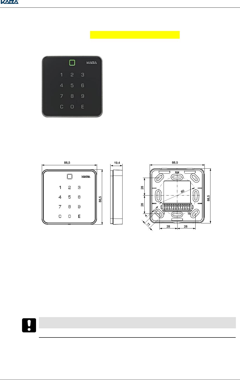
5.1 Product description
The registration unit 90 02 with integrated
antenna and keypad, together with the control
unit, represents a fully-integrated solution for
access control with simultaneous convenient
identification of the user.
In addition, for identification in the event of
increased security requirements, it is also
possible to demand verification of the user via
entry of his/her personal PIN code.
This registration unit is suitable for both internal
and external applications.
Additional Product descriptions:
Door code entry for access without a badge
(Code lock function)
Control of alarm systems
5.2 Dimensions
Height incl. rear panel: 19,4 mm
Height spacer frame: 26,4 mm
External dimensions
Dimensions of rear panel/spacer frame
5.3 Installation
5.3.1 Preparation
If necessary, drill holes for the frame bracket.
A dimension drawing of the frame can be found above.
Surface cable mounting:
Use the spacer frame (only indoors).
Break open the cable inlet on the spacer frame.
Lead the cable away at the bottom or at the side in a siphon shape.
NOTICE
Only connect the wires when the power is switched off.
Kaba Registration 90 02 / Kone Registration 90 02
22 TM_ RegistrationUnits_201604_en KONE US CAN IN ARBEIT.docx
Procedure
1.
Pull the cable through the rear panel or the spacer frame.
Screw the rear panel or the spacer frame to an even surface.
The rear panel or spacer frame must not lose its shape.
Small bumps can be balanced out using the sealing pad.
Lead the cable away in a siphon shape to prevent the ingress of water.
2.
Connect the cable strands to the connection terminal.
An overview showing the assignment of connection terminals can be found in Chapter 5.4.2
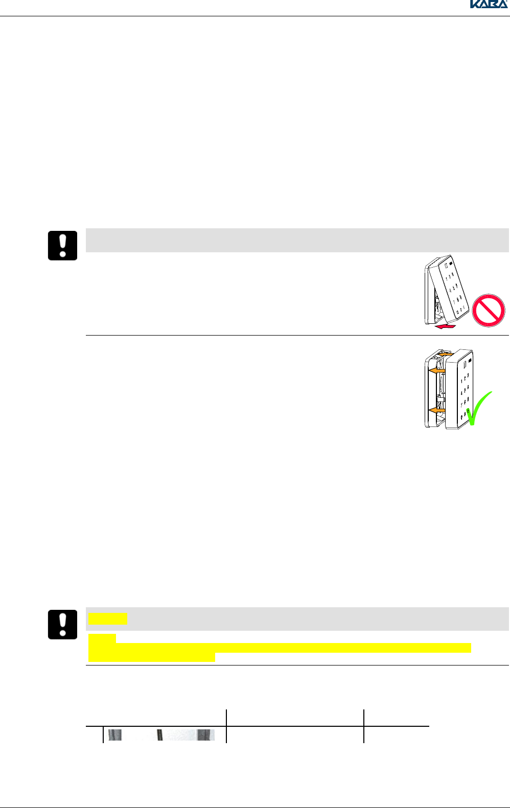
NOTICE
The pin strip can be damaged. Observe the following instructions
3.
Slide the PIN keypad in a parallel position over the rear panel or the spacer
frame.
4.
Press the PIN keypad against the rear panel or the spacer frame until it clicks into position at both
the top and the bottom.
5.4 Connection
5.4.1 Connection with quickwireTM Technology
With the innovative quickwire technology, the wiring is performed completely separately from the
electronics on the mounting plate (rear panel or spacer frame). The electronics are mounted as a unit
during commissioning. The practical click connection makes mounting simpler and means the
registration unit is quickly changed in case of repair.
In addition, it is possible to upgrade from a registration unit without a PIN to a registration unit with PIN
with no or minimal changes to wiring.
NOTICE
Notice:
The device may only be supplied with SELV (Safety Extra Low Voltage) and LPS (Limited Power Source),
according to IEC/UL/CSA 60950-1.
5.4.2 Connecting the Coaxial Cable
Terminal Number
Meaning
Control Unit
6
Antenna cable shield wire
AS

Kaba Registration 90 02 / Kone Registration 90 02
TM_ RegistrationUnits_201604_en KONE US CAN IN ARBEIT.docx 23
7
Antenna cable inner conductor
A+
Kaba Registration 90 02 / Kone Registration 90 02
24 TM_ RegistrationUnits_201604_en KONE US CAN IN ARBEIT.docx
5.4.3 Operation of the keypad
When operating the keypad, please observe the following:
Press your finger (covering as large an area as possible) gently in the center of the relevant key
field
The keypad does not react to fingernails, gloves or just fingertips
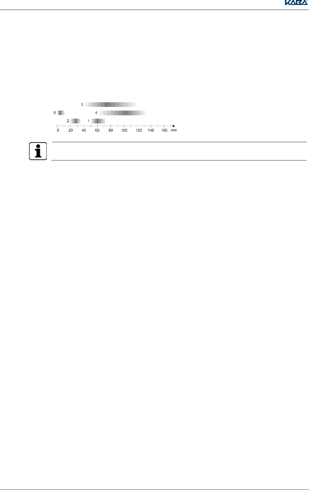
5.5 Typical Maximum Reading Distance
1 = Badge, ISO 14443A
2 = Key fob, ISO 14443A
3 = Badge, LEGIC RF
4 = Badge, ISO 15693
5 = Kaba elolegic smart key, LEGIC RF
The Kaba elolegic smart key can only be used to a limited extent.
5.5.1 Reading and Writing Distance with Direct Mounting on Metal
If the registration unit is mounted directly on a metallic surface, the reading and writing distance is
approx. 10% smaller than an RFID neutral environment (wood, masonry).
Kaba Registration 90 02 / Kone Registration 90 02
TM_ RegistrationUnits_201604_en KONE US CAN IN ARBEIT.docx 25
5.6 Technical Data
Rear Panel / Spacer Frame:
Material
PC-ABS GF10
Frame:
Material
PC-ABS
Front:
Material
ESG float glass
Dimensions:
With rear panel (concealed cable mounting)
88.5 x 88.5 x 19.4 mm (length x width x height)
With spacer frame (surface cable mounting)
88.5 x 88.5 x 26.4mm (length x width x height)
Protection Type IEC 60529
IP54;
Only with concealed cable mounting and sealing
pad
Temperature Range
- 25° - +70°C (operation)
- 40° - +85°C (storage)
Ambient Conditions
Relative humidity
0% - 95% non condensing
Application
Concealed cable mounting with real panel
Surface cable mounting with spacer frame
Mounting possible directly on metal or neutral
subsurface
Coaxial cable
Recommended: RG 174/U, 50 Ohm
Supplier: Huber + Suhner
max. lenght 30 m
Power supply
The registration unit is powerd by the host
control device
Notice:
The device may only be supplied with SELV (Safety
Extra Low Voltage) and LPS (Limited Power Source),
according to IEC/UL/CSA 60950-1.
Kaba Registration 90 02 / Kone Registration 90 02
26 TM_ RegistrationUnits_201604_en KONE US CAN IN ARBEIT.docx
5.7 Dismantling
1. Insert a screwdriver (no. 1) into the bottom of the opening and press it
upwards.The quick-release lock opens up.
NOTICE
The pin strip can be damaged. Observe the following instructions.
2. Slightly raise the bottom of the PIN keypad (max. 10º).
3. Pull the PIN keypad forwards in a parallel position.
5.7.1 Accessories
Rear panel SL for concealed cable mounting
Spacer frame SL for surface cable mounting
Sealing pad, black
5.8 Conformity
See Chapter 8.
Kaba Registration 90 00 / Kone registration unit PCB
TM_ RegistrationUnits_201604_en KONE US CAN IN ARBEIT.docx 27
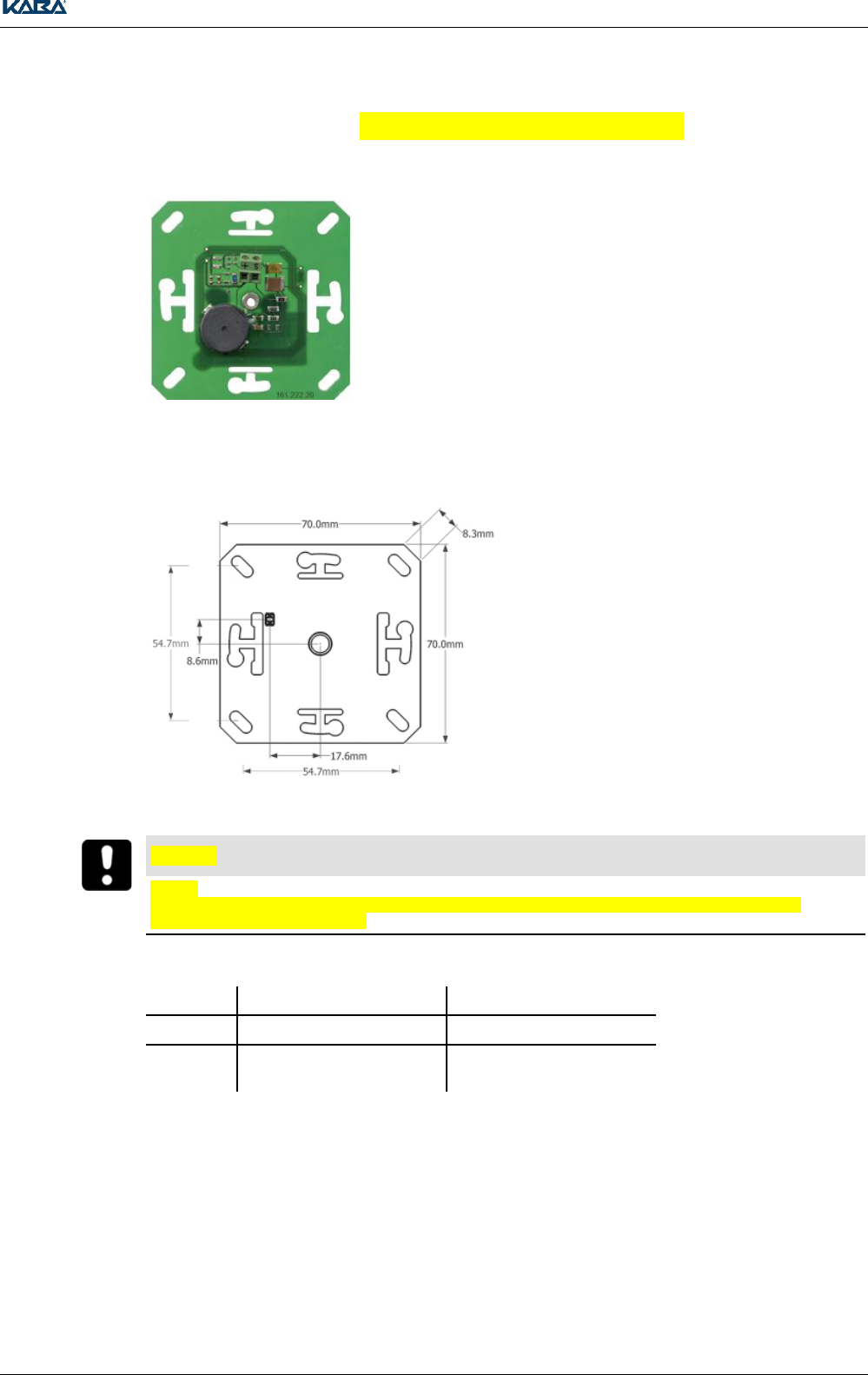
6 Kaba Registration 90 00 / Kone registration unit PCB
6.1 Product description
The registration unit 9, together with the control
unit, represents a fully-integrated solution for
access control with simultaneous convenient
identification of the user. The registration unit is
suitable for mounting in on-site assortment of
switches or sockets or in customer-specific
solutions. The new antenna design observes
sufficient distance to the environment and is
therefore also suitable for mounting in a metallic
environment. Owing to the simple cabling,
installation costs are very low.
6.2 Mounting and Connection
6.2.1 Mounting and Connection
This registration unit can be simply integrated in
current European standard installation sockets
(size I). The thread insert with thread M3 is
suitable for the mounting of various European
covers.
Suitable Housing / Covers
See Accessories
To ensure the visibility of the LED, the cover in
the area of the LED must have a drill hole of
Ø 5.2 mm.
NOTICE
Notice:
The device may only be supplied with SELV (Safety Extra Low Voltage) and LPS (Limited Power Source),
according to IEC/UL/CSA 60950-1.
Connecting the Coaxial Cable
Terminal
Meaning
Control Unit
S
Antenna cable shield wire
AS
+
Antenna cable inner
conductor
A+
6.2.2 LED
The registration unit 90 00 is equipped with a 2-color, red/green LED. To ensure the visibility of the
LED, the cover in the area of the LED must have a drill hole of Ø 5.2 mm, where you would like visual
as well as acoustic signaling.
The LED is mechanically compatible with registration unit LA-PB solutions
Kaba Registration 90 00 / Kone registration unit PCB
28 TM_ RegistrationUnits_201604_en KONE US CAN IN ARBEIT.docx
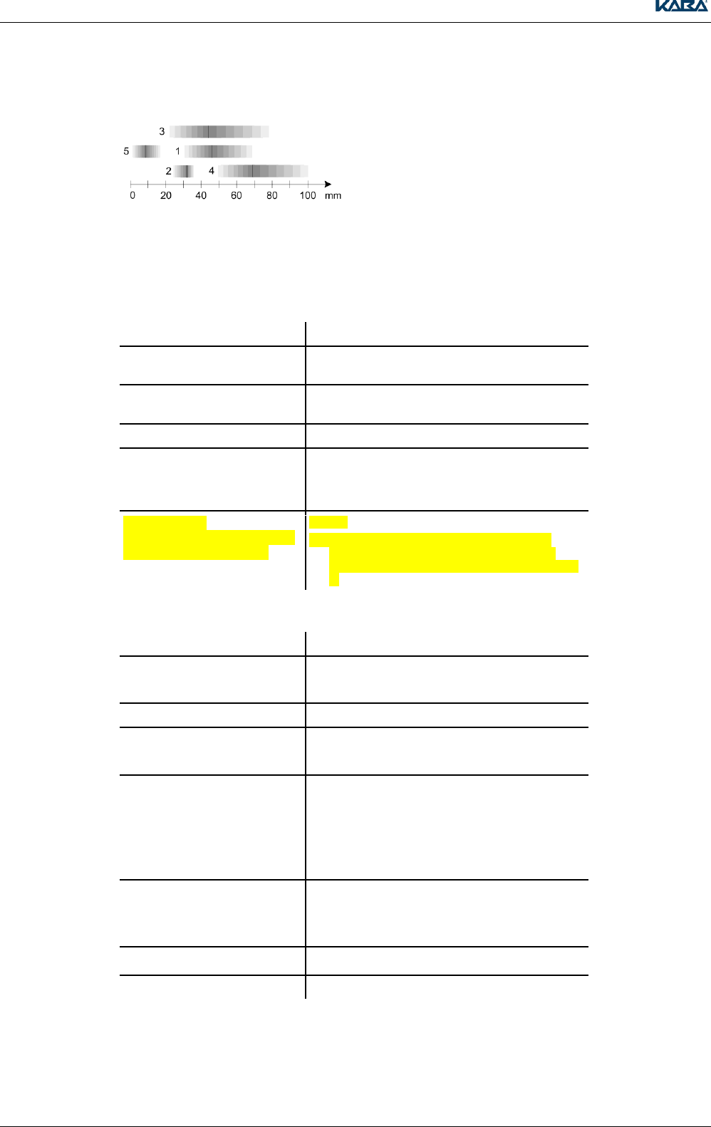
6.3 Typical Maximum Reading Distance
1 = Badge, ISO 14443A
2 = Key fob, ISO 14443A
3 = Badge, LEGIC RF
4 = Badge, ISO 15693
5 = Kaba elolegic smart key, LEGIC RF
6.3.1 Reading and Writing Distance with Direct Mounting on Metal
If the registration unit is mounted in metal facades or a metal frame, the reading and writing distance
will be approx. 10% smaller than in an RFID neutral environment (wood, masonry).
6.4 Technical Data
Dimensions
70 x 70 x ~13 mm (length x width x height)
Temperature Range
- 25° - +70°C (operation)
- 40° - +85°C (storage)
Ambient Conditions
Relative humidity
0% - 95%, non condensing
Application
On-site assortment of switches or sockets
Coaxial cable
Recommended: RG 174/U, 50 Ohm
Supplier: Huber + Suhner
max. lenght 30 m
Power supply
The registration unit is powerd
by the host control device
Notice:
The device may only be supplied with SELV
(Safety Extra Low Voltage) and LPS (Limited
Power Source), according to IEC/UL/CSA 60950-
1.
6.4.1 Accessories
Supplier
Type
Amacher
Basico
Domino
Busch-Jäger
Feller
EDIZIOdue, pluggable
NUP
Gira
E2
Event
Surface
S-Color
Standard
Jung
CD500
CD Play
ST 550
Legrand
Diplomat
Merten
6.5 Conformity
See Chapter 8.
Dismantling and disposal
TM_ RegistrationUnits_201604_en KONE US CAN IN ARBEIT.docx 29
7 Dismantling and disposal
7.1 Dismantling / Put out of operation
To dismantle the device in an access control system, proceed as follows:
1. During online operation: Check the configuration of the host system
2. Dismantle the device, see chapters Dismantling
7.2 Disposal
7.2.1 Disposing of packaging
Dispose of packaging in an environmentally responsible manner.
The packaging materials are recyclable. Do not throw the packaging away with domestic waste;
instead, send it for recycling.
7.2.2 Disposing of the device
NOTICE
Before disposal, the system/device must be put out of operation by the sales partner (see Chapter 7.1,
page 29).
Old devices contain valuable recyclable materials which should be recovered.
This product meets the requirements of the WEEE Directive and, in accordance with DIN standard
EN 50419, is labeled with the WEEE crossed-out trash can symbol (see Chapter 12.1.6, page 106).
This symbol indicates the separate disposal of electrical and electronic equipment in EU countries.
Do not dispose of electrical devices with general waste
Used devices contain valuable recyclable materials which must be recycled. Used devices should
therefore be disposed of via the collection system used in your country.
Disposal in Germany:
After use, Kaba GmbH undertakes to carry out the proper disposal of the supplied goods in line with
legal requirements (the ElektroG law in Germany). All costs incurred for the transport of goods to the
manufacturer's plant will be paid by the owner of the used electronic equipment.
Disposal in Switzerland:
Send the device to an electronic equipment collection facility. Contact the local authorities for further
information.
Disposal in Austria:
Do not throw the device out with household waste. Dispose of the device and used batteries in
accordance with the Act on Disposal of Waste Electrical and Electronic Equipment (Verordnung über
Entsorgung von Elektro- und Elektronik-Altgeräten – VREG/WEEE) at a local collection point for
waste electronic equipment.
RoHS
This device fulfills the requirements of Guideline 2011/65/EU of the European Parliament and
Council of June 8, 2011, to limit the use of certain hazardous materials in electrical and electronic
equipment.
Conformity
30 TM_ RegistrationUnits_201604_en KONE US CAN IN ARBEIT.docx
8 Conformity
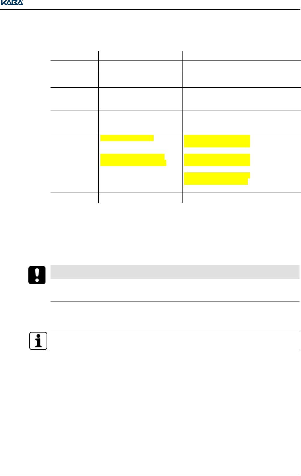
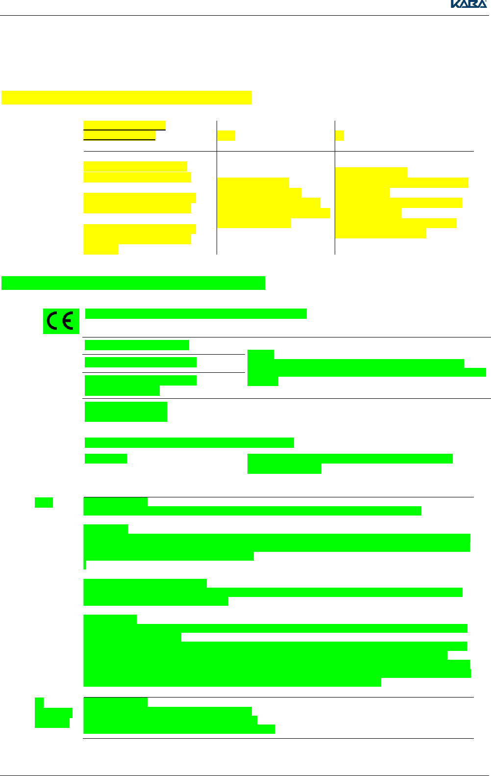
8.1 FCC- and IC- tested registration units
FCC- and IC- tested
registration units
FCC
IC
Kone regsitration unit PCB
Tested Standard:
FCC Code of Federal
Regulations, CFR 47, Part
15, Sections 15.205, 15.207,
15.215 and 15.225
Tested Standard:
Industry Canada Radio Standards
Specifications
RSS-GEN Issue 4, Sections 8.8,
8.9 and 8.10 and
RSS-210 Issue 8, Section A2.6
(Category I Equipment)
Kaba registration unit 90 00
Kaba registration unit 90 01 /
Kone registration unit 90 01
Kaba registration unit 90 02 /
Kone registration unit 90 02
8.2 Conformity Kone Registration Unit PCB
The registration unit conforms to the following standards:
EN 60950-1:2006/A2:2013
Notice:
The device may only be supplied with SELV (Safety Extra Low
Voltage) and LPS (Limited Power Source), according to IEC/UL/CSA
60950-1.
UL 60950-1:2007/R:2014-10
CAN/CSA-C22.2 No. 60950-
1:2007/A2:2014-10
EN 300 330-1 V1.7.1
EN 300 330-2 V1.5.1
In accordance with the provisions of EC directive:
1999/5/EG
Radio and Telecommunications Terminal Equipment
Directive (R&TTE).
FCC
Tested Standard:
FCC Code of Federal Regulations, CFR 47, Part 15, Sections 15.205, 15.207, 15.215 and 15.225
FCC § 15.19
This device complies with Part 15 of the FCC rules. Operation is subject to the following two conditions: (1) This
device may not cause harmful interference, and (2) this device must accept any interference received, including
interference that may cause undesired operation.
.
FCC § 15.21 (Warning Statement)
[Any] changes or modifications not expressly approved by the party responsible for compliance could void the
user’s authority to operate the equipment.
FCC § 15.105
Note: This equipment has been tested and found to comply with the limits for a Class A digital device, pursuant
to part 15 of the FCC Rules.
These limits are designed to provide reasonable protection against harmful interference when the equipment is
operated in a commercial environment. This equipment generates, uses, and can radiate radio frequency
energy and, if not installed and used in accordance with the instruction manual, may cause harmful interference
to radio communications. Operation of this equipment in a residential area is likely to cause harmful interference
in which case the user will be required to correct the interference at his own expense..
IC
(Industry
Canada)
Tested Standard:
Industry Canada Radio Standards Specifications
RSS-GEN Issue 4, Sections 8.8, 8.9 and 8.10 and
RSS-210 Issue 8, Section A2.6 (Category I Equipment)
Conformity
TM_ RegistrationUnits_201604_en KONE US CAN IN ARBEIT.docx 31
ICES-003
This Class A digital apparatus complies with Canadian ICES-003.
Cet appareil numérique de la classe A est conforme à la norme NMB-003 du Canada.
Canada RSS-GEN 8.4
This device complies with Industry Canada’s licence-exempt RSSs. Operation is subject to the following two
conditions:
(1) This device may not cause interference; and
(2) This device must accept any interference, including interference that may cause undesired operation of the
device.
Le présent appareil est conforme aux CNR d’Industrie Canada applicables aux appareils radio exempts de
licence. L’exploitation est autorisée aux deux conditions suivantes :
1) l’appareil ne doit pas produire de brouillage;
2) l’utilisateur de l’appareil doit accepter tout brouillage radioélectrique subi, même si le brouillage est
susceptible d’en compromettre le fonctionnement.
RoHS
This device fulfills the requirements of Guideline 2011/65/EU of the European Parliament and
Council of June 8, 2011, to limit the use of certain hazardous materials in electrical and electronic
equipment.
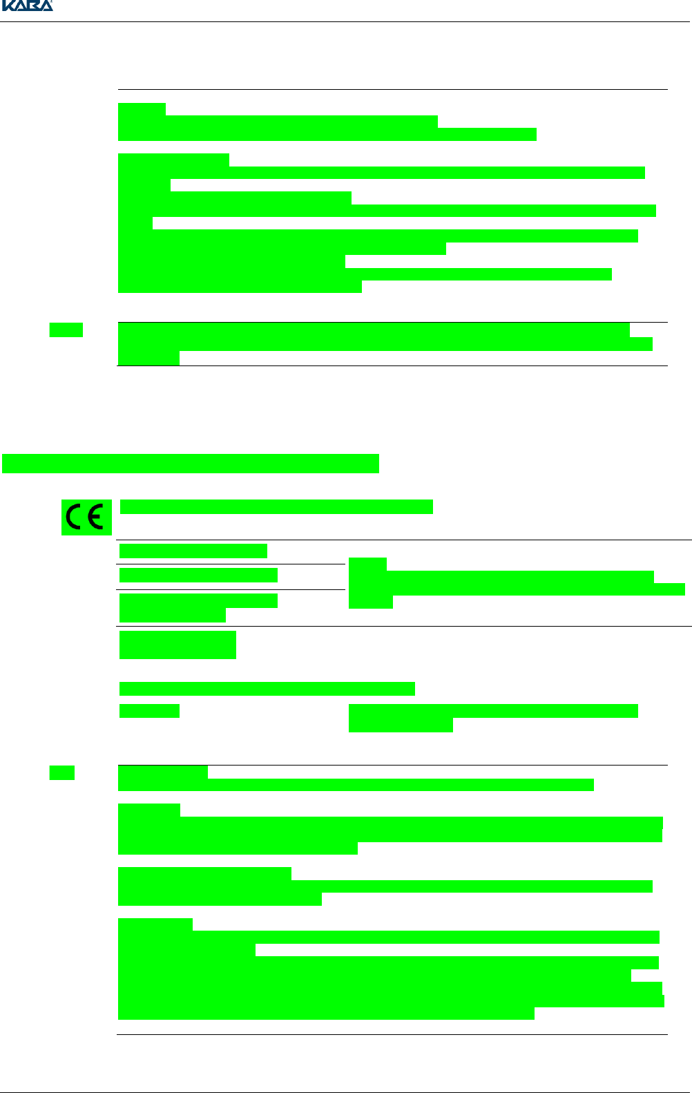
8.3 Conformity Kaba Registration Unit 90 00
The registration unit conforms to the following standards:
EN 60950-1:2006/A2:2013
Notice:
The device may only be supplied with SELV (Safety Extra Low
Voltage) and LPS (Limited Power Source), according to IEC/UL/CSA
60950-1.
UL 60950-1:2007/R:2014-10
CAN/CSA-C22.2 No. 60950-
1:2007/A2:2014-10
EN 300 330-1 V1.7.1
EN 300 330-2 V1.5.1
In accordance with the provisions of EC directive:
1999/5/EG
Radio and Telecommunications Terminal Equipment
Directive (R&TTE).
FCC
Tested Standard:
FCC Code of Federal Regulations, CFR 47, Part 15, Sections 15.205, 15.207, 15.215 and 15.225
FCC § 15.19
This device complies with Part 15 of the FCC rules. Operation is subject to the following two conditions: (1) This
device may not cause harmful interference, and (2) this device must accept any interference received, including
interference that may cause undesired operation.
FCC § 15.21 (Warning Statement)
[Any] changes or modifications not expressly approved by the party responsible for compliance could void the
user’s authority to operate the equipment.
FCC § 15.105
Note: This equipment has been tested and found to comply with the limits for a Class A digital device, pursuant
to part 15 of the FCC Rules.
These limits are designed to provide reasonable protection against harmful interference when the equipment is
operated in a commercial environment. This equipment generates, uses, and can radiate radio frequency
energy and, if not installed and used in accordance with the instruction manual, may cause harmful interference
to radio communications. Operation of this equipment in a residential area is likely to cause harmful interference
in which case the user will be required to correct the interference at his own expense.
Conformity
32 TM_ RegistrationUnits_201604_en KONE US CAN IN ARBEIT.docx
IC
(Industry
Canada)
Tested Standard:
Industry Canada Radio Standards Specifications
RSS-GEN Issue 4, Sections 8.8, 8.9 and 8.10 and
RSS-210 Issue 8, Section A2.6 (Category I Equipment)
ICES-003
This Class A digital apparatus complies with Canadian ICES-003.
Cet appareil numérique de la classe A est conforme à la norme NMB-003 du Canada.
Canada RSS-GEN 8.4
This device complies with Industry Canada’s licence-exempt RSSs. Operation is subject to the following two
conditions:
(1) This device may not cause interference; and
(2) This device must accept any interference, including interference that may cause undesired operation of the
device.
Le présent appareil est conforme aux CNR d’Industrie Canada applicables aux appareils radio exempts de
licence. L’exploitation est autorisée aux deux conditions suivantes :
1) l’appareil ne doit pas produire de brouillage;
2) l’utilisateur de l’appareil doit accepter tout brouillage radioélectrique subi, même si le brouillage est
susceptible d’en compromettre le fonctionnement.
RoHS
This device fulfills the requirements of Guideline 2011/65/EU of the European Parliament and
Council of June 8, 2011, to limit the use of certain hazardous materials in electrical and electronic
equipment.
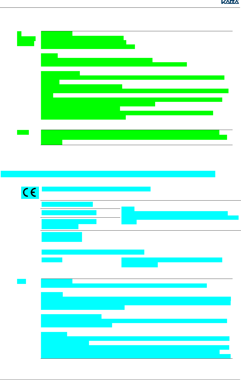
8.4 Conformity Kaba Registration Unit 90 01 / Kone Registration Unit 90 01
The registration unit conforms to the following standards:
EN 60950-1:2006/A2:2013
Notice:
The device may only be supplied with SELV (Safety Extra Low
Voltage) and LPS (Limited Power Source), according to IEC/UL/CSA
60950-1.
UL 60950-1:2007/R:2014-10
CAN/CSA-C22.2 No. 60950-
1:2007/A2:2014-10
EN 300 330-1 V1.7.1
EN 300 330-2 V1.5.1
In accordance with the provisions of EC directive:
1999/5/EG
Radio and Telecommunications Terminal Equipment
Directive (R&TTE).
FCC
Tested Standard:
FCC Code of Federal Regulations, CFR 47, Part 15, Sections 15.205, 15.207, 15.215 and 15.225
FCC § 15.19
This device complies with Part 15 of the FCC rules. Operation is subject to the following two conditions: (1) This
device may not cause harmful interference, and (2) this device must accept any interference received, including
interference that may cause undesired operation.
FCC § 15.21 (Warning Statement)
[Any] changes or modifications not expressly approved by the party responsible for compliance could void the
user’s authority to operate the equipment.
FCC § 15.105
Note: This equipment has been tested and found to comply with the limits for a Class A digital device, pursuant
to part 15 of the FCC Rules.
These limits are designed to provide reasonable protection against harmful interference when the equipment is
operated in a commercial environment. This equipment generates, uses, and can radiate radio frequency
energy and, if not installed and used in accordance with the instruction manual, may cause harmful interference
Conformity
TM_ RegistrationUnits_201604_en KONE US CAN IN ARBEIT.docx 33
to radio communications. Operation of this equipment in a residential area is likely to cause harmful interference
in which case the user will be required to correct the interference at his own expense.
IC
(Industry
Canada)
Tested Standard:
Industry Canada Radio Standards Specifications
RSS-GEN Issue 4, Sections 8.8, 8.9 and 8.10 and
RSS-210 Issue 8, Section A2.6 (Category I Equipment)
ICES-003
This Class A digital apparatus complies with Canadian ICES-003.
Cet appareil numérique de la classe A est conforme à la norme NMB-003 du Canada.
Canada RSS-GEN 8.4
This device complies with Industry Canada’s licence-exempt RSSs. Operation is subject to the following two
conditions:
(1) This device may not cause interference; and
(2) This device must accept any interference, including interference that may cause undesired operation of the
device.
Le présent appareil est conforme aux CNR d’Industrie Canada applicables aux appareils radio exempts de
licence. L’exploitation est autorisée aux deux conditions suivantes :
1) l’appareil ne doit pas produire de brouillage;
2) l’utilisateur de l’appareil doit accepter tout brouillage radioélectrique subi, même si le brouillage est
susceptible d’en compromettre le fonctionnement.
RoHS
This device fulfills the requirements of Guideline 2011/65/EU of the European Parliament and
Council of June 8, 2011, to limit the use of certain hazardous materials in electrical and electronic
equipment.
8.5 Conformity Kaba Registration Unit 90 02 / Kone Registration Unit 90 02
The registration unit conforms to the following standards:
EN 60950-1:2006/A2:2013
Notice:
The device may only be supplied with SELV (Safety Extra Low
Voltage) and LPS (Limited Power Source), according to IEC/UL/CSA
60950-1.
UL 60950-1:2007/R:2014-10
CAN/CSA-C22.2 No. 60950-
1:2007/A2:2014-10
EN 300 330-1 V1.7.1
EN 300 330-2 V1.5.1
In accordance with the provisions of EC directive:
1999/5/EG
Radio and Telecommunications Terminal Equipment
Directive (R&TTE).
FCC
Tested Standard:
FCC Code of Federal Regulations, CFR 47, Part 15, Sections 15.205, 15.207, 15.215 and 15.225
FCC § 15.19
This device complies with Part 15 of the FCC rules. Operation is subject to the following two conditions: (1) This
device may not cause harmful interference, and (2) this device must accept any interference received, including
interference that may cause undesired operation.
FCC § 15.21 (Warning Statement)
Any] changes or modifications not expressly approved by the party responsible for compliance could void the
user’s authority to operate the equipment.
FCC § 15.105
Note: This equipment has been tested and found to comply with the limits for a Class A digital device, pursuant
to part 15 of the FCC Rules.
These limits are designed to provide reasonable protection against harmful interference when the equipment is
operated in a commercial environment. This equipment generates, uses, and can radiate radio frequency
energy and, if not installed and used in accordance with the instruction manual, may cause harmful interference

Conformity
34 TM_ RegistrationUnits_201604_en KONE US CAN IN ARBEIT.docx
to radio communications. Operation of this equipment in a residential area is likely to cause harmful interference
in which case the user will be required to correct the interference at his own expense.
IC
(Industry
Canada)
Tested Standard:
Industry Canada Radio Standards Specifications
RSS-GEN Issue 4, Sections 8.8, 8.9 and 8.10 and
RSS-210 Issue 8, Section A2.6 (Category I Equipment)
ICES-003
This Class A digital apparatus complies with Canadian ICES-003.
Cet appareil numérique de la classe A est conforme à la norme NMB-003 du Canada..
Canada RSS-GEN 8.4
This device complies with Industry Canada’s licence-exempt RSSs. Operation is subject to the following two
conditions:
(1) This device may not cause interference; and
(2) This device must accept any interference, including interference that may cause undesired operation of the
device.
Le présent appareil est conforme aux CNR d’Industrie Canada applicables aux appareils radio exempts de
licence. L’exploitation est autorisée aux deux conditions suivantes :
1) l’appareil ne doit pas produire de brouillage;
2) l’utilisateur de l’appareil doit accepter tout brouillage radioélectrique subi, même si le brouillage est
susceptible d’en compromettre le fonctionnement.
RoHS
This device fulfills the requirements of Guideline 2011/65/EU of the European Parliament and
Council of June 8, 2011, to limit the use of certain hazardous materials in electrical and electronic
equipment.

Conformity
TM_ RegistrationUnits_201604_en KONE US CAN IN ARBEIT.docx 35
8.6 Declaration of conformity
Kaba GmbH, Access & Workforce Management, Albertistrasse 3, D-78056 Villingen-Schwenningen
hereby declares as the manufacturer of the device that the Compact Readers conform to the
fundamental requirements and other relevant stipulations of Directive 1999/5/EC (R&TTE).
The original declaration of conformity is available at
http://www.kaba.com/access-control/de/Sales-Support/81668/downloads.html?cat=355024
and can be downloaded in PDF format at any time.
8.7 Device mark
The following information can be found on the label:
Device designation
Article number
Serial number
Manufacturer
CE mark
WEEE labeling in accordance with DIN EN 50419
8.8 Manufacturer
Kaba GmbH
Access & Workforce Management
Albertistrasse 3
78056 Villingen-Schwenningen
Germany
Phone +49 7720 603 0
E-mail: awm.info@kaba.com
http://www.kaba.com