Kamstrup A S FLOW2100-3C Water Flow Meter User Manual 15 flowIQ2100 3c UserMan
Kamstrup A/S Water Flow Meter 15 flowIQ2100 3c UserMan
15_flowIQ2100-3c UserMan
ALWAYS use new gaskets
(Kamstrup recommends
EPDM).
The sealing surface of
the threaded connection
must be clean and level.
The adjacent piping must be parallel
and match the meter in- and outlet.
Torque
If a pipe installation is skewed to the effect that the prescribed
tightening torques would be exceeded, a meter setter or yoke should
be installed.
1” Max. 30 Nm
1”: Max. 30 Nm
flowIQ® 2100 - RF
& flowIQ® 2100 - Encoded Output
Installation guide
Kamstrup A/S • 55121224_F1_US_11.2015
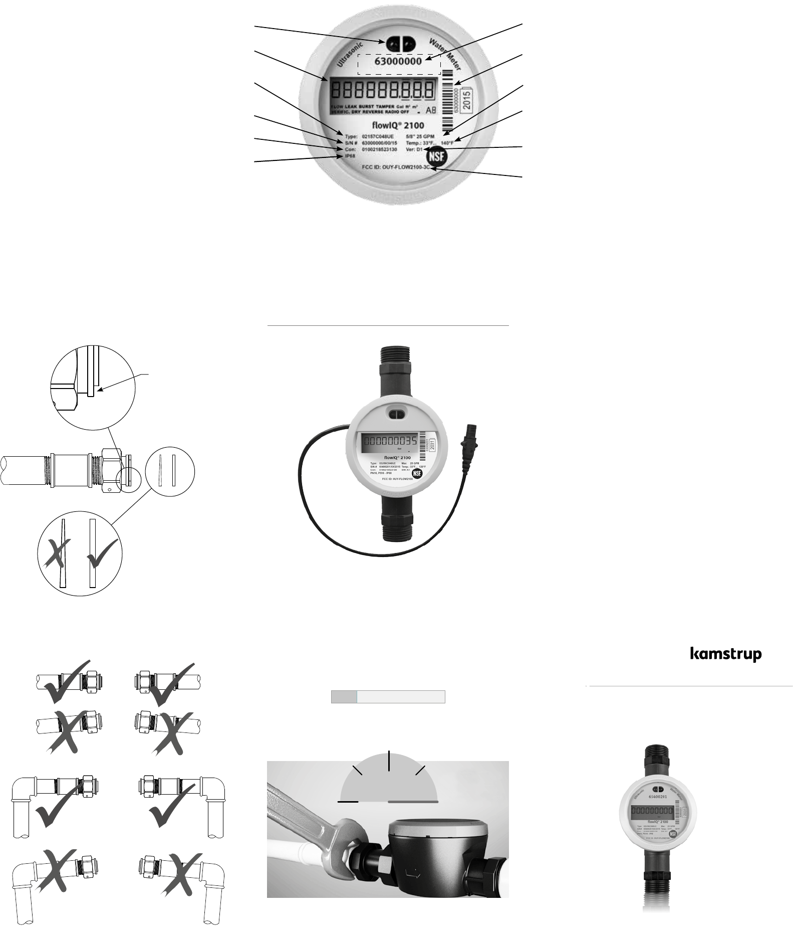
Optional customer label, (not an option for Encoded Output version)
Optical eye for reading and configuration
Digital display showing consumption
Type number
(includes information on
meter size, overall length etc.)
Serial no. and production year
Configuration of the adjustable parameters
Bar code with serial number
Software version
FCC identification
Protection Class IP68 (Waterproof/submersible)
flowIQ® 2100 - Encoded Output version
FCC Cautions
Caution: Changes or modifications not expressly approved by the
party responsible for compliance could void the user’s authority to
operate the equipment.
RF Exposure compliance statement: This device may be used with
no restrictions, since the source-based time-averaged output power
is ≤ 60/f(GHz) mW.
This device complies with Part 15 of the FCC Rules.
Operation is subject to the following two conditions:
1 This device may not cause harmful interfenrence, and
2 This device must accept any interference received, including
interference that may cause undesired operation.
Temperature range
Nominal meter size -
Max. flow for continous operation
Do not overtighten; max 30 Nm or 1/4 turn beyond handtight.
1.4 Encoded Output
Ground Connection ’GND’
must be connected to the reading device ‘GND’.
The connection ‘Power/CLK’
must be connected to the reading device ‘CLK’.
The connection ‘Data Out’
must be connected to reading device ‘data input’.
GRN – Data out
BLK – GND –
RED – Power/CLK +
The reading unit must comply with the electrical requirements of
the specification for the Sensus protocol UI 1203R20, September
2009.
Most important issues are listed below:
Type: Open Drain
Maximum input voltage: 15V
Maximum current sink: 5mA
On voltage: < 0,4V @ 3,2mA
OFF condition: R > 6MΩ
Frequent reading, more than once per hour, will reduce battery life.
Compability table
Sensus ITRON NEPTUNE
Data Grn Red Red
Ground Blk White Green
Power Red Black Black
1.2 Installation requirements
Prior to installation of flowIQ® 2100 the system should be cleaned
and flushed thoroughly. Then, install the meter with matching
couplings.
If an existing install, remove all traces of old gaskets and insert new
gaskets in original quality. Kamstrup recommends EPDM gaskets ,
which are included.
Install the meter according to the flow direction indicated by an
arrow on the side of the meter housing. An electrical grounding wire
must be installed according to local electrical regulation and for
safety reasons.
During installation it must be secured that the meter is mounted
without mechanical tension in the connection pipes. The piping
must be in line and match the meter. Do not attempt to install the
meter in a misaligned pipe system or in an opening that is too long.
Jacking the piping into place with the meter will seriously damage
the meter.
In a properly aligned piping system with new gaskets, you should be
able to mount and tighten the couplings by hand.
After hand-tightening the coupling nuts, using an open-end wrench,
tighten an extra ¼ to ½ turn on each coupling. Maximum allowable
torque is 30 Nm.
If a tight connection cannot be obtained within these limits, the
pipe installation must be corrected in order to remove strains.
Alternatively a meter setter or yoke must be installed.
Mounting the meter you must make sure that the threaded length
of the couplings does not prevent proper tightening of the sealing
surface and that couplings with similar pressure ratings are used.
For sealing, use the sealing wire holes on the lower side of the
threaded connections.
Service
When the meter has been mounted in the system neither welding
nor freezing is allowed. Dismount the meter from the system before
starting such work.
In order to facilitate replacement of the meter, shut off valves
should be mounted on both sides of the meter.
The meter is supplied with a strainer in the inlet. Check valves must
be mounted according to local regulations.
1.3 Installation angle of flowIQ® 2100
flowIQ® 2100 can be mounted at all angles and positions.
Kamstrup Headquarters recommend that the display is mounted so
that it is easy to read, if possible.
Thus, the meter can be mounted in a plain horizontal installation. It
can be mounted vertically in an ascending pipe, it can be mounted
at any angle and it can be mounted with the display pointing
downwards, e.g under a roof.
Mounting the meter in a downpipe, you must be aware that the
display in that case will be ’upside down’.
C Recommended water meter position.
D Recommended water meter position.
E Used for ”well installation”. Air build-up may occur.
F The meter functions optimally, but the display is ’upside down’.
1 General information
Read this guide before installing the water meter.
flowIQ® 2100 is a compact electronic water meter used for water
consumption measurement in the tap water supplies of homes,
commercial and industrial buildings.
flowIQ® 2100 is hermetically closed, and it is, therefore, impossible
to service the meter without breaking the seal. This means that all
service, must be carried out by an authorized Kamstrup Service
Centre.
Certain changes of configuration, however, are possible via the
built-in optical eye without dismounting the meter from the
installation. Further details appear in the data sheet.
1.1 Permissible operating conditions / measuring
ranges
Temperature media
- the water meter: 33 °F...140 °F
Pressure stage: 250 PSI
Mechanical environment: Fixed installation with minimum
vibration.
Electromagnetic
environmental class: Residential and commercial
Protection class: IP68-rated (waterproof-submersible)
Climatic environment: 35 °F...140 °F. Condensing humidity.
(indoors mounted in utility rooms and
outdoors in meter pits). Installation
in direct sunlight must be avoided.
The meter must be protected from
freezing as well.
1.5 Straight inlet
flowIQ® 2100 requires neither straight inlet nor straight outlet to
meet applicable AWWA standards. A straight inlet section will only
be necessary in case of heavy flow disturbances before the meter.
1.6 Operating pressure
In order to avoid cavitation and secure correct measurement under
all circumstances the operating pressure in the pipe installation
should observe the test conditions of AWWA M6 manual. The static
pressure, immediately after the meter (downstream), must always
be minimum 5 PSI (0.3 bar).
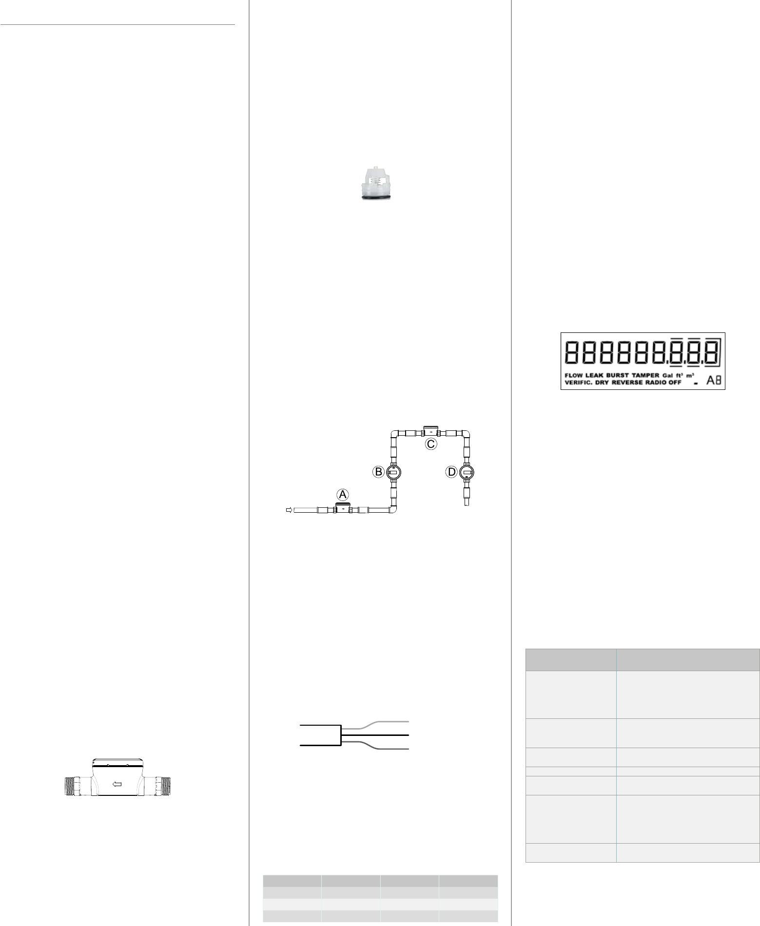
1.7 Info codes and display
When flowIQ® 2100 leaves Kamstrup Headquarters, it has been
tested and verified and the counter has been reset. The number
of gallons or CuFt are displayed by nine large digits (Bars over and
under digits indicates decimals after the comma). A number of
info codes can be displayed, of which ’DRY’ and ’RADIO OFF’ will be
activated and flash upon delivery. Furthermore, the small square in
the bottom right-hand corner flashes to indicate that the meter is
active.
Info code ’DRY’ indicates air in the meter, the info code disappears
when the meter is water-filled.
The info code ’RADIO OFF’ indicates that the meter is still in
transport mode with the built-in radio transmitter turned off. The
transmitter turns on automatically when the first quarter gallon of
water has run through the meter. The radio transmitter remains on,
and the info code signal in the display switches off The Encoded
Output version will not display ‘RADIO OFF’.
When the water is running, the symbol ’FLOW’ will turn on in the
display. If the water is stagnant, the symbol will be off.
The table below describes the different info codes in the display.
Info code flashes in the
display
Meaning
LEAK The water has not been stagnant in the
meter during the last few days.
This can be a sign of a leaky faucet or
toilet cistern.
BURST The water flow has exceeded a
preprogrammed limit for minimum 30
minutes which is a sign of a burst pipe.
TAMPER Attempt of fraud. The meter is no longer
valid for billing purposes.
DRY The meter is not water-filled.
REVERSE The water flows through the meter in the
wrong direction.
RADIO OFF* The meter is still in transport mode with
the built-in radio transmitter turned off.
The transmitter turns on automatically
when the first 1/4 gallon of water has run
through the meter.
■ (Square ‘dot’) One small flashing square indicates that
the meter is active.
* RF version only