Kamstrup A S FLOW2102 Water Flow Meter User Manual UserMan a
Kamstrup A/S Water Flow Meter UserMan a
Contents
- 1. UserMan a
- 2. UserMan b
UserMan a
flowIQ® 2102
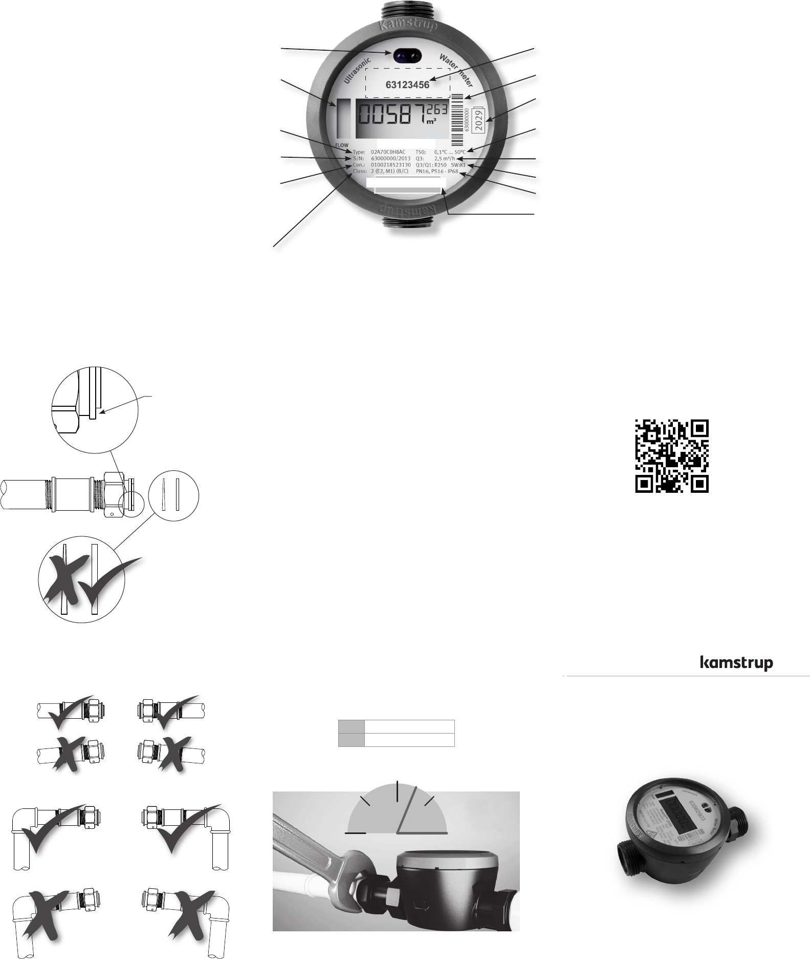
Installation guide
Optional customer label, e.g. water company logo (15x38 mm)
Optical eye for reading and configuration
Graphic flow indicator
Type number
(includes information on meter
Serial no. and prod. year
Configuration
(with information on display resolution
Accuracy class 2 according to OIML R49
Environment class: Electrical E2 and Mechanical M1
Environment class B and C according to OIML R49
Bar code with serial number
Expiry year of battery
Temperature class according to OIML R 49
Meter size Q3
Software version and dynamic range
Pressure stage and protection class
FCC identification
ALWAYS use new gaskets (PE
or EPDM).
The coupling’s sealing
surface must be clean
and even.
The piping must be parallel and match the meter.
If you have a smart phone you can enter this QR code to enter
www.kamstrup.com
Torque
If a pipe installation is skew to the effect that the prescribed
tightening torques would be exceeded, a telescopic coup-ling
ought to be installed.
¾” Max. 15 Nm
1” Max. 30 Nm
¾”: Max. 15 Nm
1”: Max. 30 Nm
DRAFT-5512XXXX_A1_CL-GB_06.2015
FCC ID: OUY-FLOW2102
flowIQ® 2102
FCC Cautions
Caution: Changes or modifications not expressly approved
by the party responsible for compliance could void the user’s
authority to operate the equipment.
RF Exposure compliance statement: This device may be used
with no restrictions, since the source-based time-averaged
output power is ≤ 60/f(GHz) mW.

1.4 Straight inlet
flowIQ® 2102 requires neither straight inlet nor straight outlet to
meet the Measuring Instruments Directive (MID) 2004/22/ EC
and OIML R49. A straight inlet section will only be necessary in
case of heavy flow disturbances before the meter.
A Recommended water meter position.
B Recommended water meter position.
C Used for ”pit installation”. Air build-up may occur.
D The meter functions optimally, but the display is ’upside-
down’.
1.5 Operating pressure
In order to avoid cavitation and secure correct measurement,
under all circumstances, the operating pressure in the pipe
installation must observe the test conditions of OIML R 49, which
means that the static pressure immediately after the meter
(downstream) must always be minimum 0.03 MPa (0.3 bar).
1.2 Installation requirements
Prior to installation of flowIQ® 2102 the system should be
flushed while a fitting piece replaces the meter. Mount the meter
with couplings. You must always use new gaskets in original
quality.
Following gaskets can be used:
Cold water Hot water
¾” 2 mm EPDM or PE 2 mm PTFE with silicate fill
1” 3 mm EPDM or PE 3 mm PTFE with silicate fill
The flow direction is indicated by an arrow on the side of the
meter housing.
During installation it must be secured that the meter is mounted
without mechanical bias in the connection pipes. The couplings
must be tightened with maximum the following torque:
If a tight connection cannot be obtained within these limits, the
pipe installation must be corrected in order to remove strains.
Alternatively, a telescopic coupling must be installed.
Such couplings can be supplied by Kamstrup A/S.
¾” 15 Nm
1” 30 Nm
For sealing you can use the sealing wire holes on the lower side
of the threaded connections.
Mounting the meter you must make sure that the threaded
length of the couplings does not prevent proper tightening of
the sealing surface, and that PN10 or PN16 couplings are used.
flowIQ® 2102 has a large-meshed strainer (filter) pre-mounted
in the meter inlet socket.
For both meter sizes 2.5 m3/h and 4.0 m3/h, a nonreturn valve,
to be mounted concealed in the meter outlet socket, is available.
Thin 2 or 3 mm gaskets must be used for mounting. Non-return
valve must be pressed into the outlet of the meter; the black
o-ring pointing inwards in the meter. Press firmly the valve, into
the meter outlet socket, until it reaches limit stop.
Gasket Gasket
Non-return valve
Flow
Service
When the meter has been mounted in the system, neither
welding nor freezing is allowed. Dismount the meter from the
system before starting such work.
In order to facilitate replacement of the meter, closing valves
should be mounted on both sides of the meter.
Under normal operating conditions no pipe strainer is required
in front of the meter. Non-return valves must be mounted
according to national local regulations.
1.3 Installation angle of flowIQ® 2102
flowIQ® 2102 can be mounted at all angles and positions.
Kamstrup A/S recommend that the display is mounted so that it
is easy to read, if possible.
Thus, the meter can be mounted in a usual horizontal
installation. It can be mounted vertically in an ascending pipe,
it can be mounted at any angle and it can be mounted with its
display facing down, e.g under a roof.
Mounting the meter in a downpipe, you must be aware that the
display in that case will be ’upside-down’.
1. General information
Read this guide before installing the water meter.
flowIQ® 2102 is a compact electronic water meter used for water
consumption measurement in the tap water supplies of homes,
commercial and industrial buildings. The meter is available in
two versions for cold and hot water respectively.
flowIQ® 2102 is intended for maintenance-free operation for up
to 16 years depending on the installed battery type.
flowIQ® 2102 is hermetically closed, and it is, therefore,
impossible to service the meter without breaking the seal. This
means that all service including battery change must be carried
out by an authorized Kamstrup Service Centre.
Certain changes of configuration, however, are possible via
the built-in optical eye without dismounting the meter from
the installation. Further details appear from data sheet and
technical description.
This device complies with Part 15 of the FCC Rules.
Operation is subject to the following two conditions:
(1) this device may not cause harmful interference, and
(2) this device must accept any interference received, including
interference that may cause undesired operation.
1.1 Permissible operating conditions / measuring
ranges
Medium temperature
cold water meter: 0.1°C...50°C
Medium temperature
hot water meter: 0.1°C...70°C
Pressure stage: PN16
Mechanical environment: M1 Fixed installation with minimum
vibration.
Electromagnetic
environmental class: E1 and E2. Residential and
commercial
Protection class: IP68
Climatic environment: 2°C...55°C. Condensing humidity.
(indoors mounted in utility rooms
and outdoors in meter wells).
Installation in direct sunlight must
be avoided.
1.6 Info codes and display
When flowIQ® 2102 leaves Kamstrup A/S, it has been tested and
verified and the counter has been reset.
The number of m3 is displayed by five large digits. The small
digits are decimals after the point.
A number of info codes can be displayed, of which DRY
and RADIO OFF will be activated and flash upon delivery.
Furthermore, the two small squares in the bottom right-hand
corner flash to indicate that the meter is active.
Info code DRY indicates there is air in the meter; the info code
disappears when the meter is water-filled.
The info code RADIO OFF indicates that the meter is still in
transport mode with the built-in radio transmitter turned off. The
transmitter turns on automatically when the first litre of water
has run through the meter. The radio transmitter remains on,
and the info code signal in the display switches off.
The flow arrows in the left side of the display indicate water flow
through the meter. If the water is stagnant, all arrows will be off.
The table below describes the different info codes in the display.
The figure after the ’A’ states how many times the meter
has been adjusted. In a completely new meter both of these
characters will be out.
Laboratories which have reverified and adjusted or reset the
meter must supply the meter with a label with information on
the current adjustment figure.
Info code flashes in the
display
Meaning
LEAK The Water has not been stagnant
in the meter for minimum one
continuous hour during the latest 24
hours.
This can be a sign of a leaky faucet or
toilet cistern.
BURST The water flow has exceeded a
preprogrammed limit for minimum
30 minutes which is a sign of a burst
pipe.
TAMPER Attempt of fraud. The meter is no
longer valid for billing purposes.
DRY The meter is not water-filled.
REVERSE The water flows through the meter in
the wrong direction.
RADIO OFF The meter is still in transport mode
with the built-in radio transmitter
turned off. The transmitter turns on
automatically when the first litre of
water has run through the meter.
■■(two square ’dots’) Two small squares alternately flashes,
indicating that the meter is active