Kasda Networks KW5212 802.11b/g/n 4 Port VDSL2 Router User Manual ZXKW5212H Manual4 06 ipv6
Kasda Networks inc 802.11b/g/n 4 Port VDSL2 Router ZXKW5212H Manual4 06 ipv6
UserManual.wiki
>
Kasda Networks
>
KW5212 User Manual
Users Manual
Navigation menu
Upload a User Manual
Namespaces
Wiki Guide
HTML
PDF
Info
Views
User Manual
Discussion / Help
Navigation

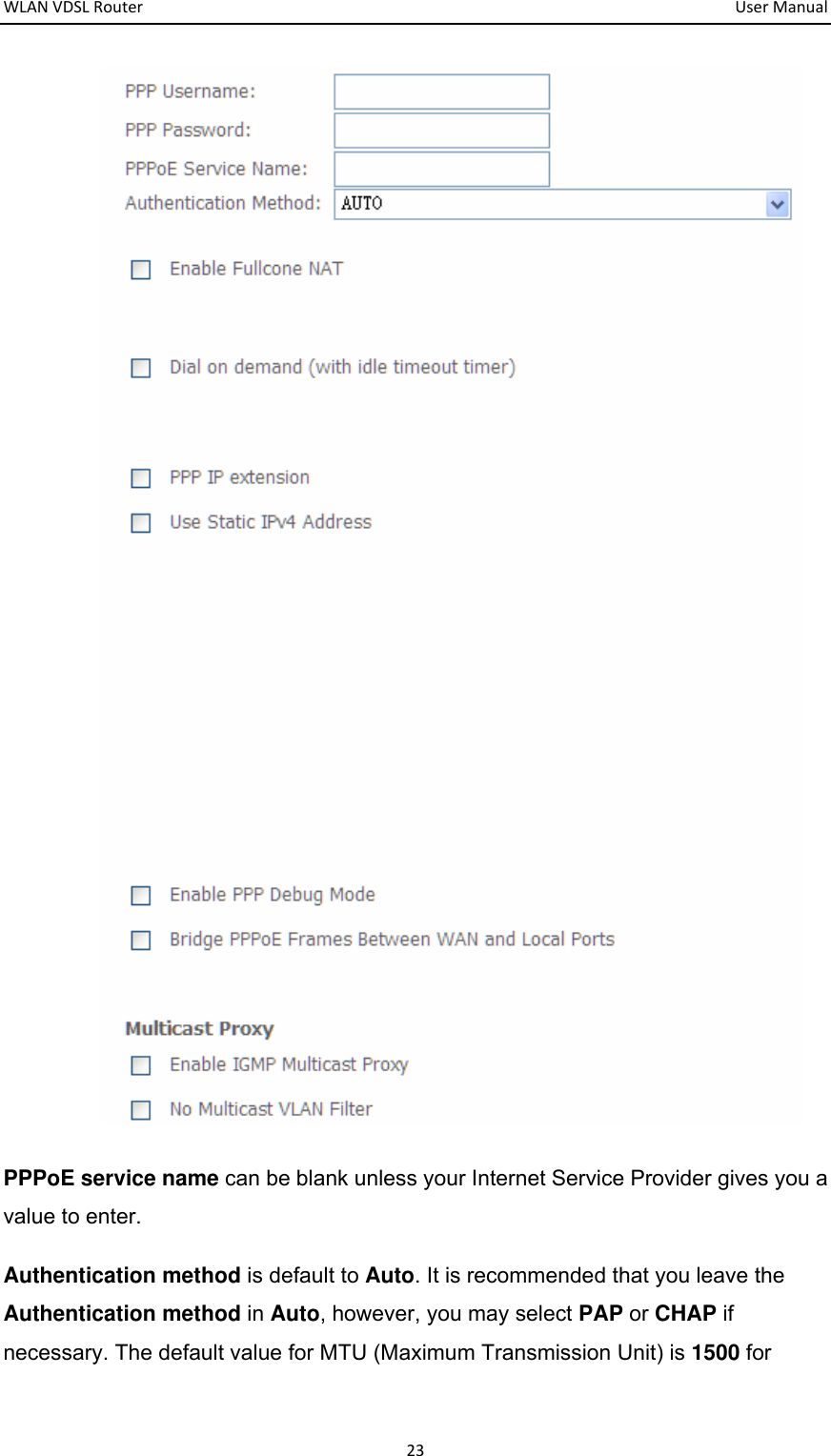
![1. This equipment complies with Part 68 of the FCC rules and the requirements adopted by the ACTA. On the bottom of this equipment is a label that contains, among other information, a product identifier in the format US:AAAEQ##TXXXX. If requested, this number must be provided to the telephone company. 2. A plug and jack used to connect this equipment to the premises wiring and telephone network must comply with the applicable FCC Part 68 rules and requirements adopted by the ACTA. A compliant telephone cord and modular plug is provided with this product. It is designed to be connected to a compatible modular jack that is also compliant. See installation instructions for details. 3. telephone company will notify you in advance that temporary discontinuance of service may be required. But if advance notice isn't practical, the telephone company will notify the customer as soon as possible. Also, you will be advised of your right to file a complaint with the FCC if you believe it is necessary. 4. The telephone company may make changes in its facilities, equipment, operations or procedures that could affect the operation of the equipment. If this happens the telephone company will provide advance notice in order for you to make necessary modifications to maintain uninterrupted service. 5. warranty information, Service can be facilitated through our office at: Kaito Electronics,Inc. 5185 Cliffwood Dr. Montclair CA 91763 Tel: 909 628 6088 ,Fax: 909 628 7999 If the equipment is causing harm to the telephone network, the telephone company may request that you disconnect the equipment until the problem is resolved. 6. Please follow instructions for repairing if any (e.g. battery replacement section); otherwise do not alternate or repair any parts of device except specified. For repair procedures, follow the instructions outlined under the limited warranty. 7. Connection to party line service is subject to state tariffs. Contact the state public utility commission, public service commission or corporation commission for information. 8. If your home has specially wired alarm equipment connected to the telephone line, ensure the installation of this [equipment ID:DL] does not disable your alarm equipment. If you have questions about what will disable alarm equipment, consult your telephone company or a qualified installer. 9. If the telephone company requests information on what equipment is connected to their lines, inform them of: a) The ringer equivalence number [01B] b) The USOC jack required [RJ11C] Facility Interface Codes (“FIC”) [METALLIC ] Service Order Codes (“SOC”) [9.0Y] c) 10. The REN is used to determine the number of devices that may be connected to a telephone line. Excessive RENs on a telephone line may result in the devices not ringing in response to an incoming call. In most but not all areas, the sum of RENs should not exceed five (5.0). To If trouble is experienced with this equipment [US: U5IDL01BKW5212], for repair or If this equipment [US:U5IDL01BKW5212] causes harm to the telephone network, the The FCC Registration Number[US:U5IDL01BKW5212]](https://usermanual.wiki/Kasda-Networks/KW5212/User-Guide-2060911-Page-45.png)
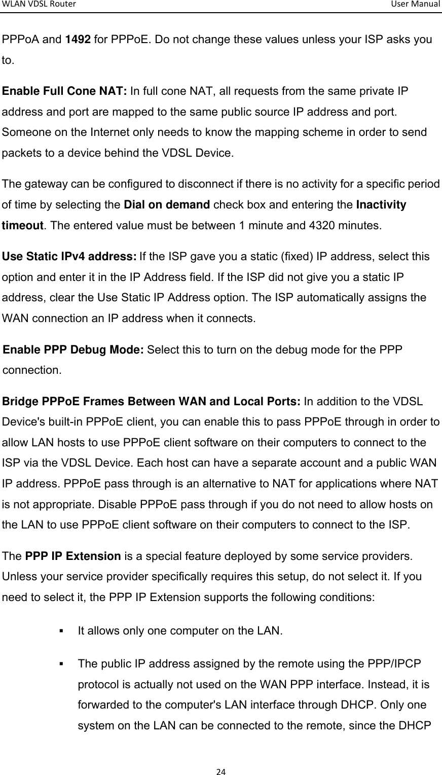
![be certain of the number of devices that may be connected to a line, as determined by the total RENs, contact the local telephone company. The REN for this product is part of the product identifier that has the format US:AAAEQ##TXXXX. The digits represented by ## are the REN without a decimal point. For this product the FCC Registration number is [US: U5IDL01BKW5212] indicates the REN would be 01B.](https://usermanual.wiki/Kasda-Networks/KW5212/User-Guide-2060911-Page-46.png)