Kasda Networks KW52283 4 Port DSL wireless Router User Manual KE318EU
Kasda Networks inc 4 Port DSL wireless Router KE318EU
UserManual.wiki
>
Kasda Networks
>
KW52283 User Manual
Users Manual
Navigation menu
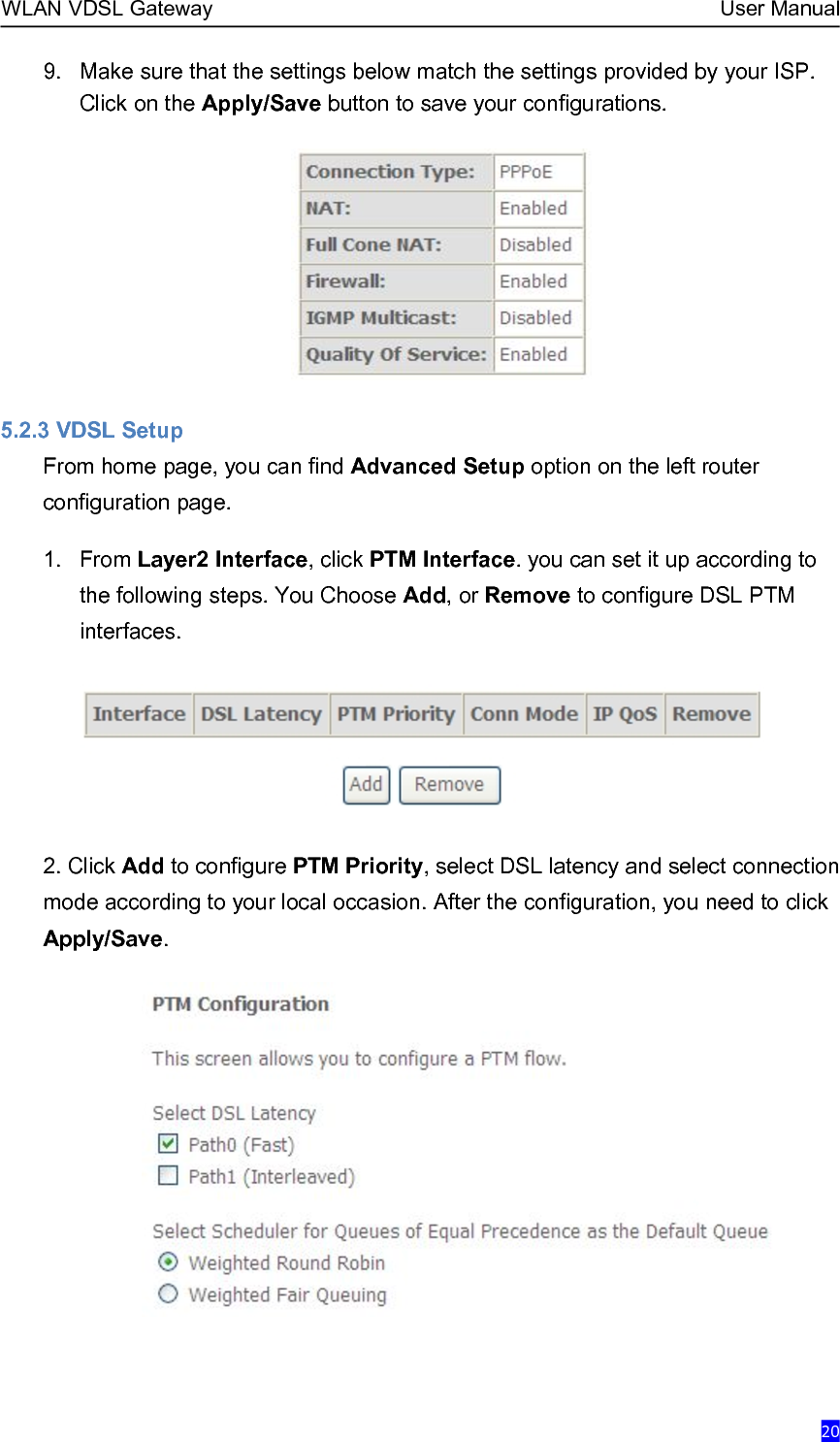
Upload a User Manual
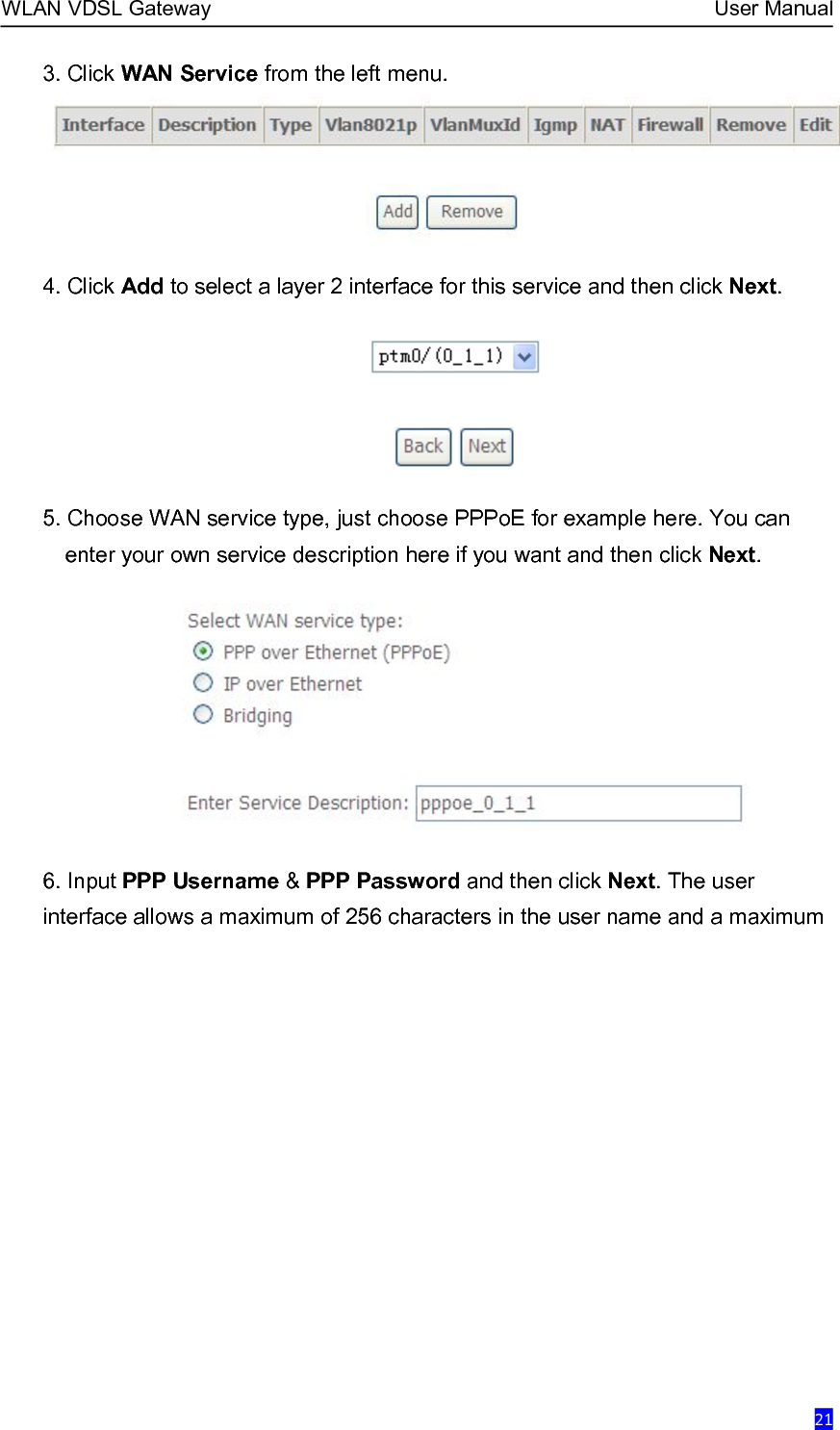
Namespaces
Wiki Guide
HTML
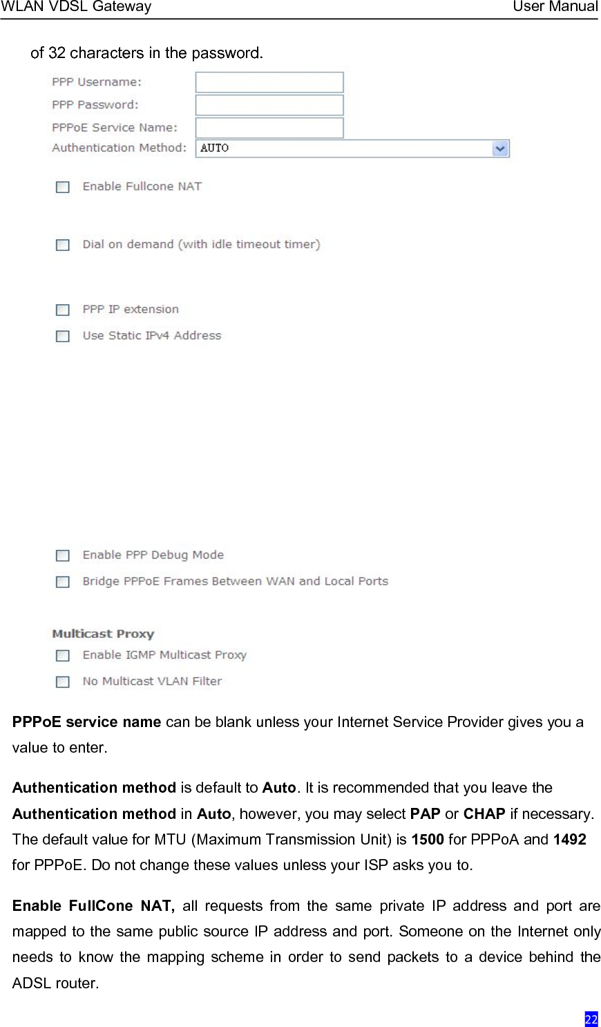
PDF
Info
Views
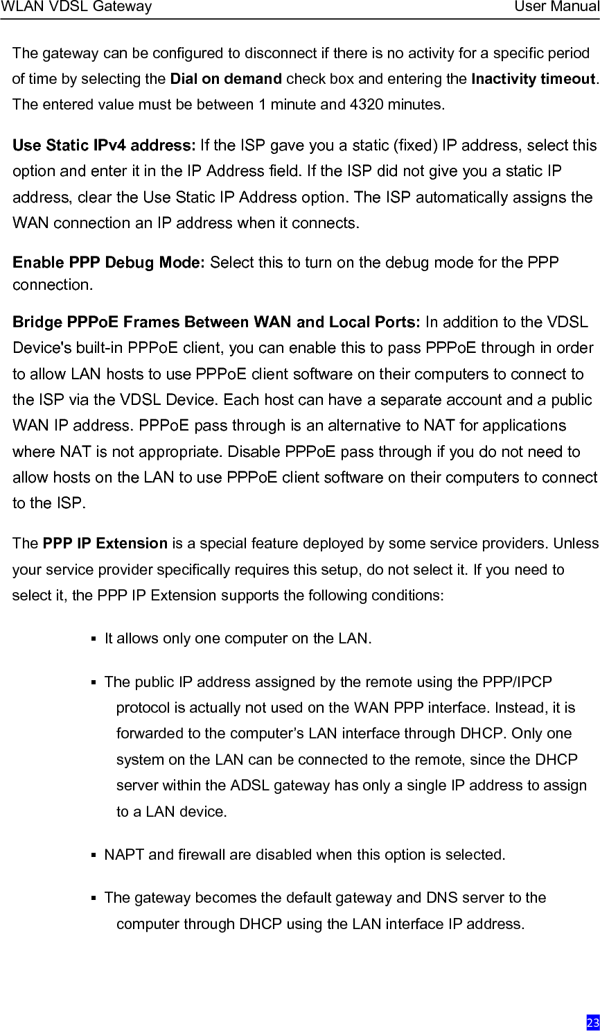
User Manual
Discussion / Help
Navigation
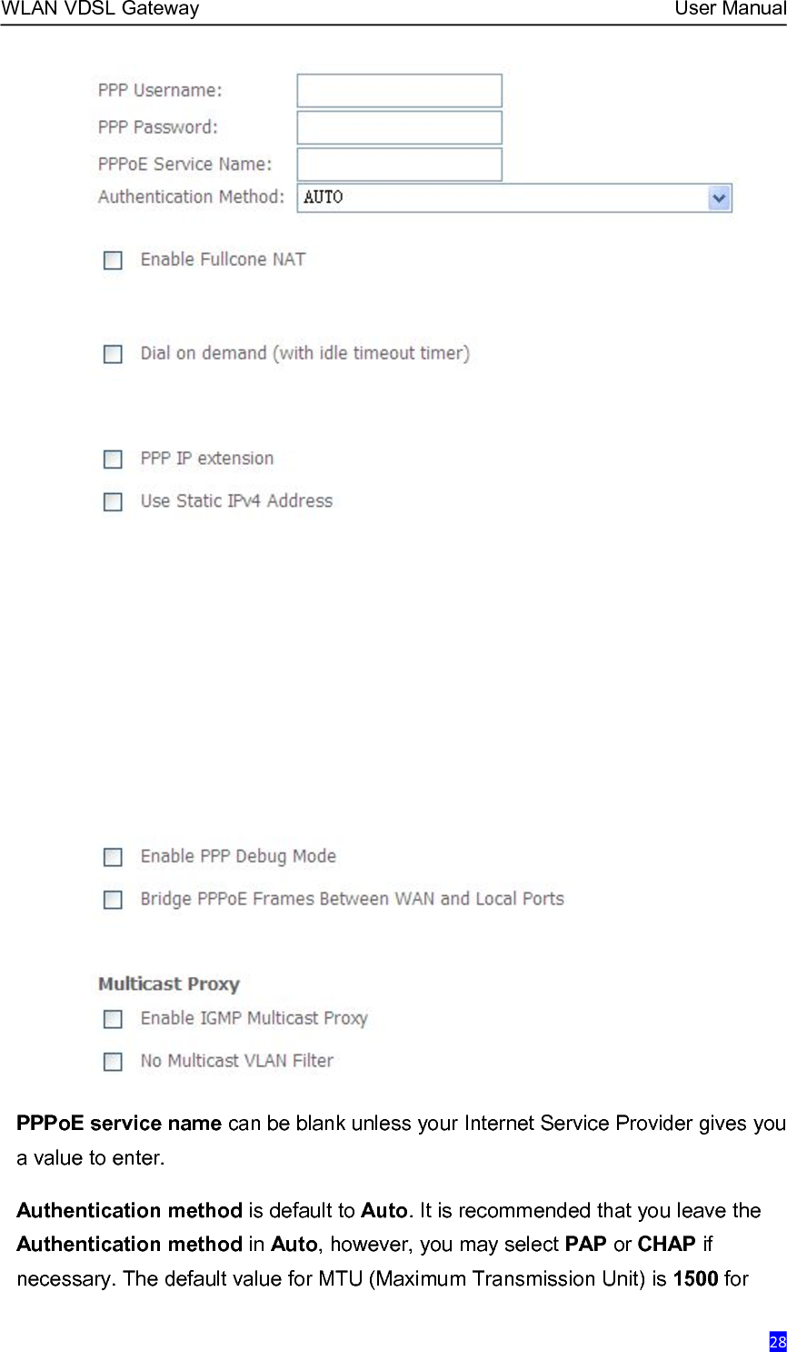
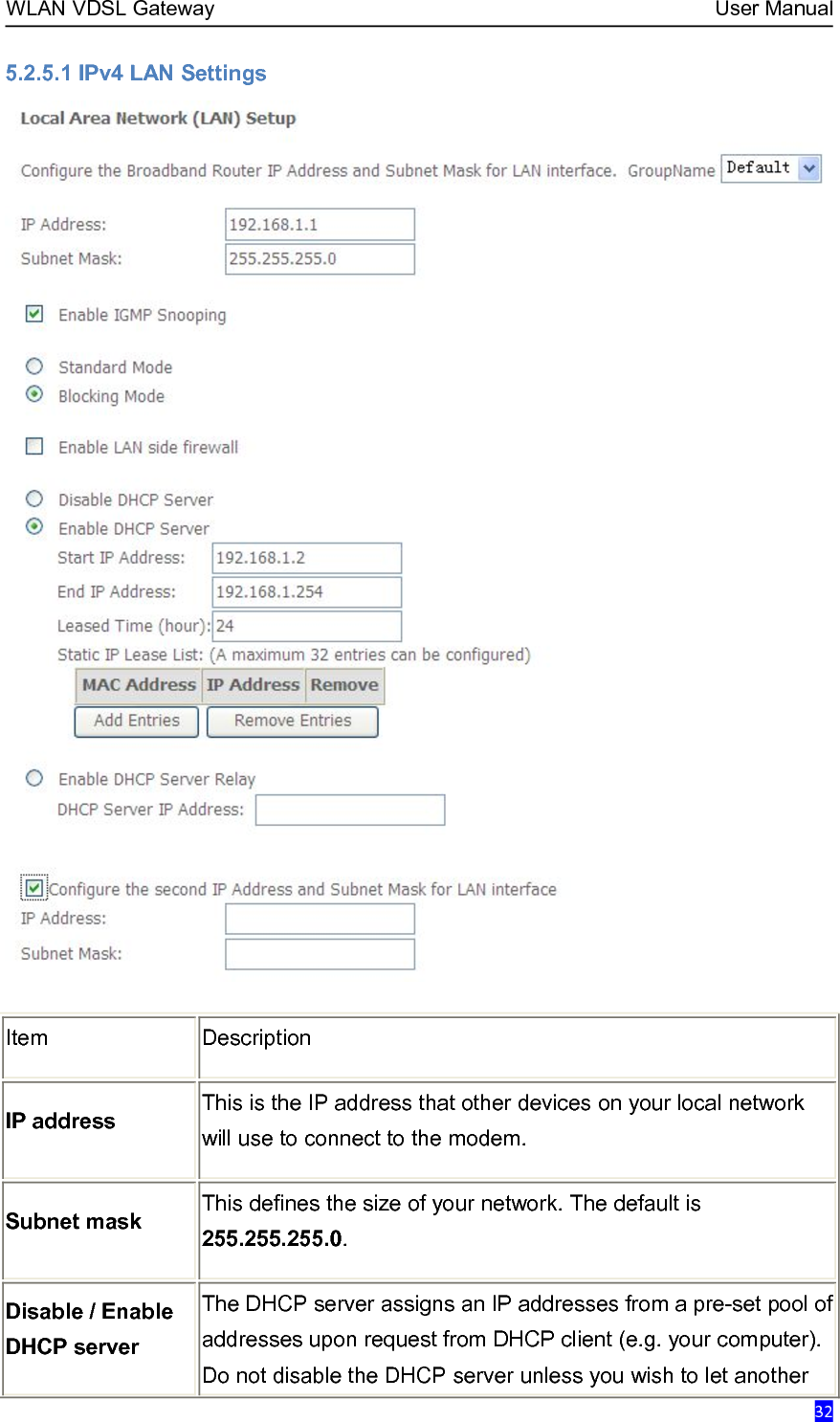
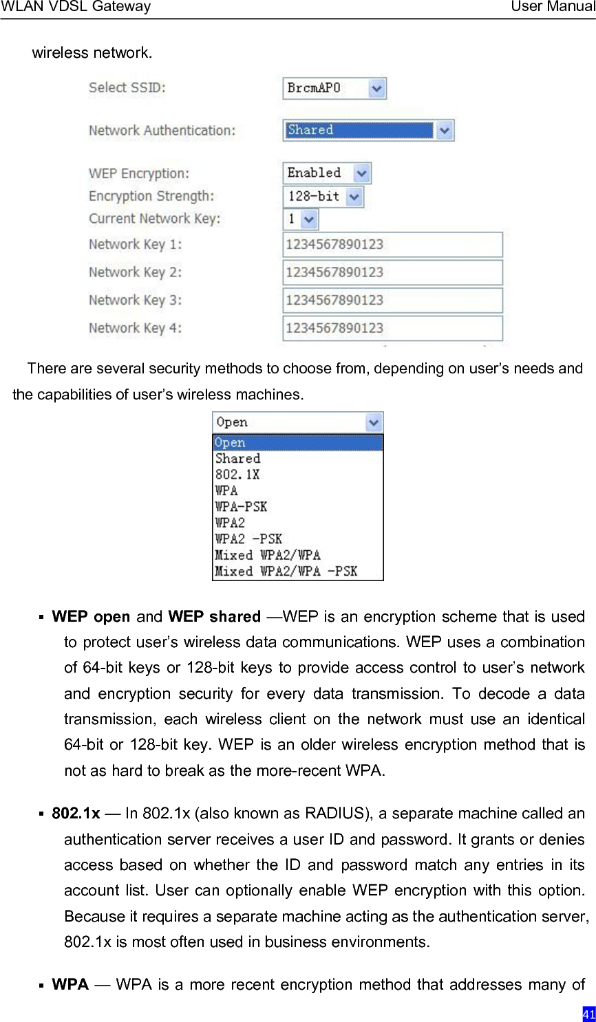
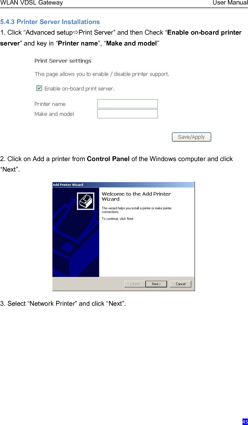
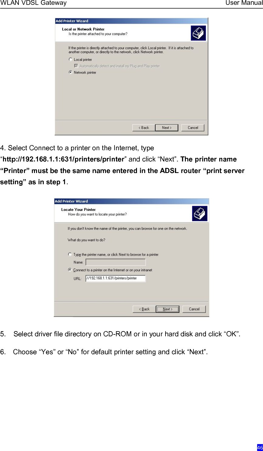
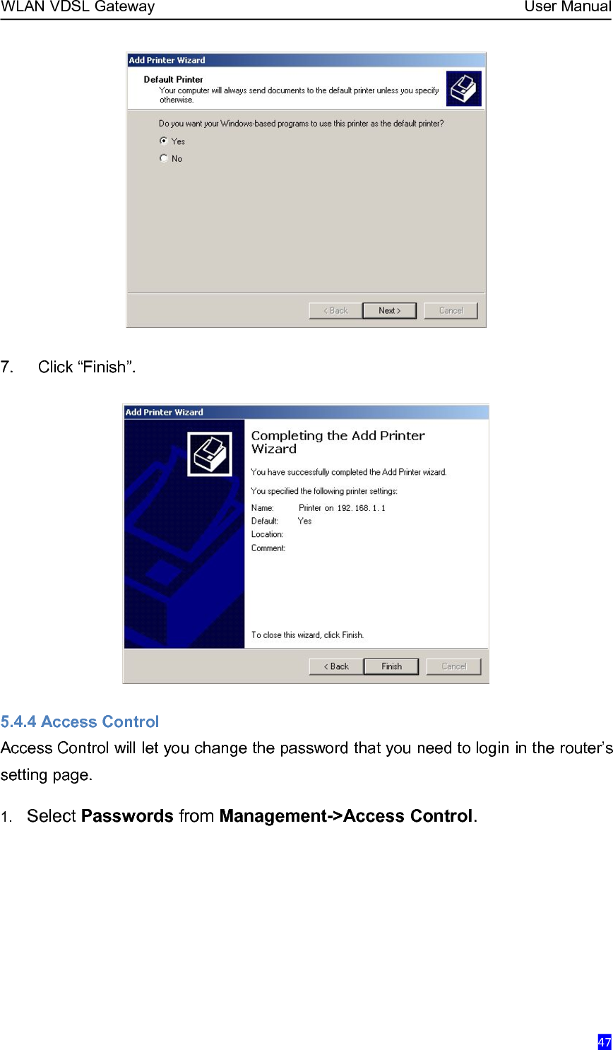
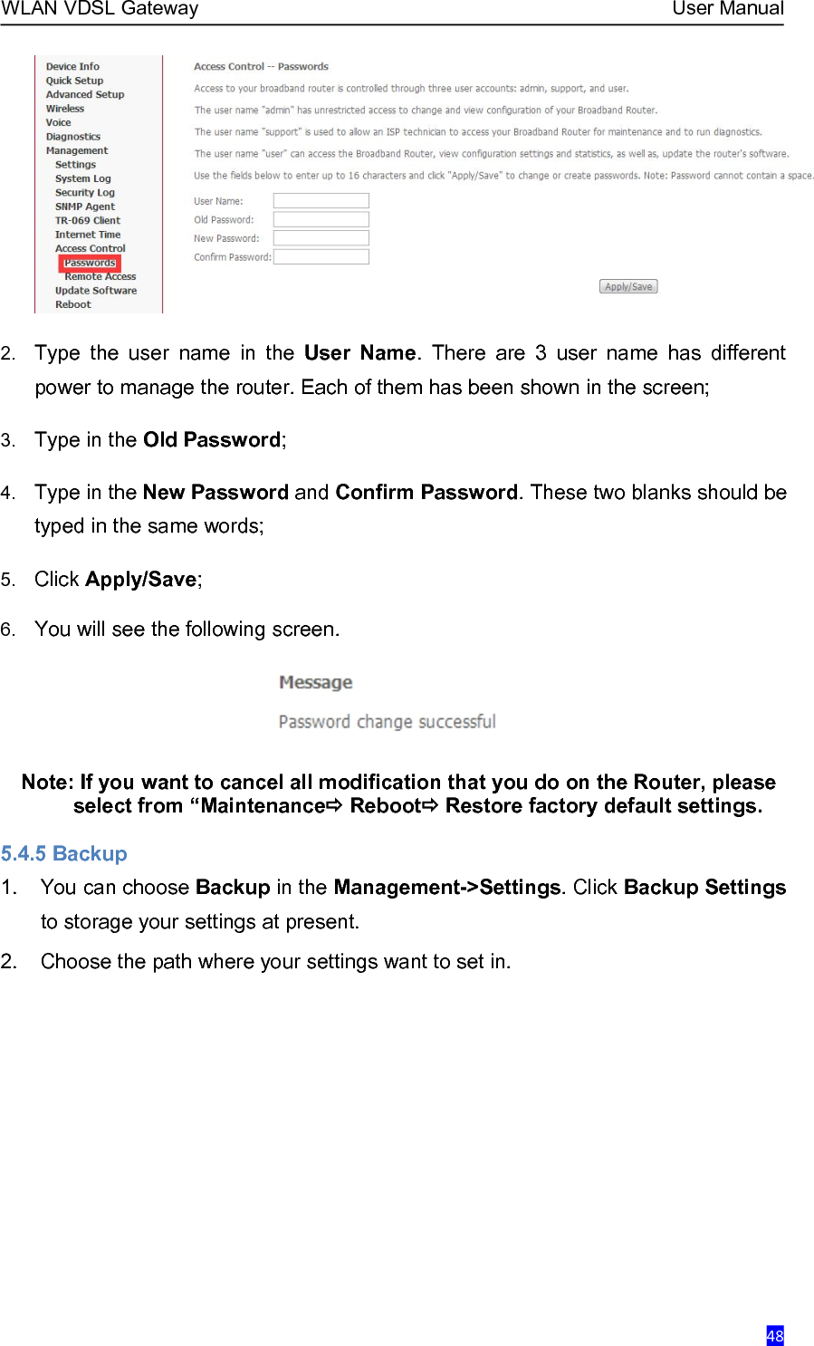
![WLAN VDSL Gateway User Manual7. Connection to party line service is subject to state tariffs. Contact the state publicutility commission, public service commission or corporation commission for information.8. If your home has specially wired alarm equipment connected to the telephone line,ensure the installation of this does not disable your alarm equipment. If you have questionsabout what will disable alarm equipment, consult your telephone company or a qualifiedinstaller.9. If the telephone company requests information on what equipment is connected totheir lines, inform them of:a) The ringer equivalence number [0.1B]b) The USOC jack required [RJ11C]c) Facility Interface Codes (“FIC”) [NA]d) Service Order Codes (“SOC”) [NA]e) The FCC Registration Number10. The REN is used to determine the number of devices that may be connected to atelephone line. Excessive RENs on a telephone line may result in the devices not ringing inresponse to an incoming call. In most but not all areas, the sum of RENs should not exceedfive (5.0). To be certain of the number of devices that may be connected to a line, asdetermined by the total RENs, contact the local telephone company. The REN for thisproduct is part of the product identifier that has the format US:AAAEQ##TXXXX. The digitsrepresented by ## are the REN without a decimal point. For this product the FCCRegistration number is indicates the REN would be 0.1B.11. If this product is equipped with a corded or cordless handset, it is hearing aidcompatible.](https://usermanual.wiki/Kasda-Networks/KW52283/User-Guide-2809647-Page-6.png)