Kasda Networks KW52283 4 Port DSL wireless Router User Manual KE318EU
Kasda Networks inc 4 Port DSL wireless Router KE318EU
Users Manual

KW52283
4 Port DSL wireless Router
Kasda Networks Inc.
深圳市宏成数字科技股份有限公司
www.kasdanet.com

WLAN VDSL Gateway User Manual
NOTICE
This document contains proprietary information protected by copyright, and this Manual
and all the accompanying hardware, software, and documentation are copyrighted. All
rights are reserved. No part of this document may be photocopied or reproduced by
mechanical, electronic, or other means in any form.
The manufacturer does not warrant that the hardware will work properly in all
environments and applications, and makes no warranty or representation, either
expressed or implied, with respect to the quality, performance, merchantability, or
fitness for a particular purpose of the software or documentation. The manufacturer
reserves the right to make changes to the hardware, software, and documentation
without obligation to notify any person or organization of the revision or change.
All brand and product names are the trademarks of their respective owners.
© Copyright 2015
All rights reserved.

WLAN VDSL Gateway User Manual
FCC Warning:
Any Changes or modifications not expressly approved by the party responsible for
compliance could void the user's authority to operate the equipment.
This device complies with part 15 of the FCC Rules. Operation is subject to the following
two conditions: (1) This device may not cause harmful interference, and (2) this device
must accept any interference received, including interference that may cause undesired
operation.
Note: This equipment has been tested and found to comply with the limits for a Class B
digital device, pursuant to part 15 of the FCC Rules. These limits are designed to provide
reasonable protection against harmful interference in a residential installation. This
equipment generates, uses and can radiate radio frequency energy and, if not
installed and used in accordance with the instructions, may cause harmful interference to
radio communications. However, there is no guarantee that interference will not occur in a
particular installation. If this equipment does cause harmful interference to radio or
television reception, which can be determined by turning the equipment off and on, the user
is encouraged to try to correct the interference by one or more of the following measures:
—Reorient or relocate the receiving antenna.
—Increase the separation between the equipment and receiver.
—Connect the equipment into an outlet on a circuit different from that to which the receiver
is connected.
—Consult the dealer or an experienced radio/TV technician for help.

WLAN VDSL Gateway User Manual
FCC Radiation Exposure Statement:
This equipment complies with FCC radiation exposure limits set forth for an uncontrolled
environment .This equipment should be installed and operated with minimum distance
20cm between the radiator& your body.
This transmitter must not be co-located or operating in conjunction with any other antenna
or transmitter.

WLAN VDSL Gateway User Manual
Customer Information
1. This equipment complies with Part 68 of the FCC rules and the requirements
adopted by the ACTA. On the bottom of this equipment is a label that contains, among
other information, a product identifier in the format US:AAAEQ##TXXXX. If requested, this
number must be provided to the telephone company.
2. A plug and jack used to connect this equipment to the premises wiring and
telephone network must comply with the applicable FCC Part 68 rules and requirements
adopted by the ACTA. A compliant telephone cord and modular plug is provided with this
product. It is designed to be connected to a compatible modular jack that is also compliant.
See installation instructions for details.
3. If this equipment causes harm to the telephone network, the telephone company will
notify you in advance that temporary discontinuance of service may be required. But if
advance notice isn't practical, the telephone company will notify the customer as soon as
possible. Also, you will be advised of your right to file a complaint with the FCC if you
believe it is necessary.
4. The telephone company may make changes in its facilities, equipment, operations or
procedures that could affect the operation of the equipment. If this happens the telephone
company will provide advance notice in order for you to make necessary modifications to
maintain uninterrupted service.
5. If trouble is experienced with this equipment, for repair or warranty information,
Service can be facilitated through our office .If the equipment is causing harm to the
telephone network, the telephone company may request that you disconnect the equipment
until the problem is resolved.
6. Please follow instructions for repairing if any (e.g. battery replacement section);
otherwise do not alternate or repair any parts of device except specified. For repair
procedures, follow the instructions outlined under the limited warranty.

WLAN VDSL Gateway User Manual
7. Connection to party line service is subject to state tariffs. Contact the state public
utility commission, public service commission or corporation commission for information.
8. If your home has specially wired alarm equipment connected to the telephone line,
ensure the installation of this does not disable your alarm equipment. If you have questions
about what will disable alarm equipment, consult your telephone company or a qualified
installer.
9. If the telephone company requests information on what equipment is connected to
their lines, inform them of:
a) The ringer equivalence number [0.1B]
b) The USOC jack required [RJ11C]
c) Facility Interface Codes (“FIC”) [NA]
d) Service Order Codes (“SOC”) [NA]
e) The FCC Registration Number
10. The REN is used to determine the number of devices that may be connected to a
telephone line. Excessive RENs on a telephone line may result in the devices not ringing in
response to an incoming call. In most but not all areas, the sum of RENs should not exceed
five (5.0). To be certain of the number of devices that may be connected to a line, as
determined by the total RENs, contact the local telephone company. The REN for this
product is part of the product identifier that has the format US:AAAEQ##TXXXX. The digits
represented by ## are the REN without a decimal point. For this product the FCC
Registration number is indicates the REN would be 0.1B.
11. If this product is equipped with a corded or cordless handset, it is hearing aid
compatible.

WLAN VDSL Gateway User Manual
0
Content
1 OVERVIEW..................................................................................................................................... 2
1.1 FEATURES........................................................................................................................2
1.1.1 Data rate.............................................................................................................................2
1.1.2 VDSL Compliant................................................................................................................2
1.1.3 Wireless.............................................................................................................................. 2
1.1.4 Network Protocol & Features.......................................................................................... 2
1.1.5 ATM Capabilities............................................................................................................... 3
1.1.6 FIREWALL......................................................................................................................... 3
1.1.7 Management Support.......................................................................................................4
1.1.8 Operating System Support.............................................................................................. 4
1.1.9 Environmental....................................................................................................................4
1.2 PACKET CONTENTS............................................................................................................. 4
1.3 SYSTEM REQUIREMENTS.................................................................................................... 4
1.4 FACTORY DEFAULTS........................................................................................................... 5
1.5 WARNINGS AND CAUTIONS................................................................................................. 5
2 HARDWARE DESCRIPTION.......................................................................................................6
3 HARDWARE INSTALLATION.................................................................................................... 8
4 PC CONFIGURATION GUIDE.................................................................................................... 9
4.1 FOR WINDOWS 7............................................................................................................... 9
4.2 FOR WINDOWS 8...............................................................................................................9
4.3 FOR WINDOWS XP............................................................................................................ 9
4.4 FOR MAC OS X................................................................................................................ 9
5 WEB-BASED MANAGEMENT GUIDE.................................................................................. 10
5.1 SETTING PAGE...................................................................................................................10
5.2 INTERNET ACCESS CONFIGURATION................................................................................11
5.2.1 Quick Setup Routing.......................................................................................................11
5.2.2 ADSL Setup..................................................................................................................... 15
5.2.3 VDSL Setup..................................................................................................................... 20
5.2.4 Router Mode Setup.........................................................................................................25
5.2.5 LAN Settings.................................................................................................................... 31
5.3 WIRELESS SETTING........................................................................................................... 36
5.3.1 Basic..................................................................................................................................36
5.3.2 Advanced Settings..........................................................................................................37

WLAN VDSL Gateway User Manual
1
5.3.3 Security.............................................................................................................................39
5.4 MANAGEMENT..................................................................................................................42
5.4.1 Remote Access............................................................................................................... 42
5.4.2 TR-069 Client...................................................................................................................43
5.4.3 Printer Server Installations............................................................................................ 45
5.4.4 Access Control................................................................................................................ 47
5.4.5 Backup.............................................................................................................................. 48
5.4.6 Restore Default............................................................................................................... 49
5.4.7 Update.............................................................................................................................. 50
APPENDIX: FREQUENT ASKED QUESTIONS......................................................................... 51
1. POWER, HARDWARE CONNECTIONS,AND LEDS.........................................................................51
2. DEVICE ACCESS AND LOGIN......................................................................................................... 52
3. INTERNET ACCESS......................................................................................................................... 53

WLAN VDSL Gateway User Manual
2
1 Overview
Thank you for choosing our product. The KW52283 is a Wireless VDSL router
combining an VDSL modem, an 802.11g wireless router, a 5-port switch, a printer
server host port, bringing high-speed wireless Internet connection to a home or office.
1.1 Features
1.1.1 Data rate
Downstream data rate up to 100 Mbps
Upstream data rate up to 50Mbps
1.1.2 VDSL Compliant
ITU G.992.1 (G.DMT)
ITU G.993.2 (G.vdsl2) (Profile 8a, 8b, 8c, 8d, 12a,12b and 17a)
ITU G.992.2 (G.Lite)
ITU G.994.1 (G.hs)
ITU G.992.3 (G.DMT.BIS)
ITU G.992.4 (G.lite.bis)
ITU G.992.5
Compatible with all T1.413 issue 2 (full rate DMT over analog
POTS), and CO DSLAM equipment
TR69 compliant with ACS
1.1.3 Wireless
Fully IEEE 802.11b & IEEE 802.11g & IEEE 802.11n compatible.
Wireless data rate up to 300Mbps
Operating in the unlicensed 2.4 GHz ISM band
Multi SSID
Supports 64/128 bits WEP,WPA,WPA2,WPA/WPA2-PSK,802.1x
1.1.4 Network Protocol & Features
Ethernet to ADSL Self-Learning Transparent Bridging

WLAN VDSL Gateway User Manual
3
Internet Control Message Protocol (ICMP)
IP Static Routing
Routing Information Protocol (RIP, RIPv2)
Network Address Translation (NAT)
Virtual Server, Port Forwarding
Dynamic Host Configuration Protocol (DHCP)
DNS Relay, DDNS
IGMP Proxy
Simple Network Time Protocol (SNTP)
VPN pass-through (IPSec/PPTP/L2TP)
Parent control
1.1.5 ATM Capabilities
RFC 1483 Multi-protocol over ATM “Bridged Ethernet” compliant
RFC 2364 PPP over ATM compliant
RFC 2516 PPP over Ethernet compliant
ATM Forum UNI3.1/4.0 PVC - Up to 8 PVCs
VPI Range: 0-255 and VCI Range: 32-65535
UNI 3.0 & 3.1 Signaling
ATM AAL5 (Adaption Layer type 5)
OAM F4/F5
1.1.6 FIREWALL
Built-in NAT
MAC Filtering
Packet Filtering
Stateful Packet Inspection (SPI)

WLAN VDSL Gateway User Manual
4
Denial of Service Prevention (DoS)
DMZ
1.1.7 Management Support
Web Based GUI
Upgrade or update via FTP/HTTP
Command Line Interface via Telnet
Diagnostic Test
Firmware upgrade-able for future feature enhancement
1.1.8 Operating System Support
WINDOWS 98/SE/ME/2000/XP/VISTA/7
Macintosh
LINUX
1.1.9 Environmental
Operating humidity: 10%-90% non-condensing
Non-operating storage humidity: 5%-95% non-condensing
1.2 Packet Contents
The packet contents are as the following:
DSL ROUTER x 1
Power Adapter x 1
External Splitter x 1
Telephone Line x 1
Ethernet Cable x 1
CD x 1
1.3 System Requirements
Before using this ROUTER, verify that you meet the following requirements:

WLAN VDSL Gateway User Manual
5
Subscription for ADSL service. Your ADSL service provider should
provide you with at least one valid IP address (static assignment or
dynamic assignment via dial-up connection).
One or more computers, each contains an Ethernet 10/100M Base-T
network interface card (NIC).
A hub or switch, if you are connecting the device to more than one
computer.
For system configuration using the supplied web-based program: A web
browser such as Internet Explorer v5.0 or later, or Netscape v4.7 or
later.
1.4 Factory Defaults
The device is configured with the following factory defaults:
IP Address: 192.168.1.1
Subnet Mask: 255.255.255.0
SSID: WLAN
Encapsulation: LLC/SNAP-BRIDGING or VC/MUx
VPI/VCI: According to local information
1.5 Warnings and Cautions
Never install telephone wiring during storm. Avoid using a telephone
during an electrical storm. There might be a risk of electric shock from
lightening.
Do not install telephone jacks in wet locations and never use the product
near water.
To prevent dangerous overloading of the power circuit, be careful about
the designed maximum power load ratings. Not to follow the rating
guideline could result in a dangerous situation.
Please note that telephone line on modem must adopt the primary line
that directly outputs from junction box. Do not connect Router to
extension phone. In addition, if your house developer divides a
telephone line to multi sockets inside the wall of house, please only use
the telephone that has connected with the splitter of ADSL Router when
you access the Internet. Under the above condition, if you also install
telephone with anti-cheat-dial device, please pull out this kind of
telephone, otherwise ADSL Router may occur frequently off-line.
WLAN VDSL Gateway User Manual
6
2 Hardware Description
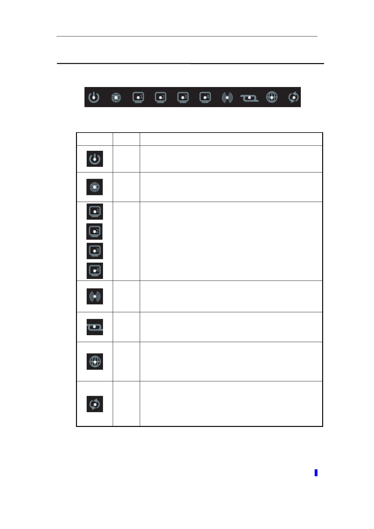
Front Panel
LED
Color
Function
Green
On: Power on
Off: No power
Green
On: GE LAN port link established and active via LAN port
Blinking: DSL data activity occurs
Off: No GE LAN port link via LAN port
Green
On: LAN link established and active via LAN port
Blinking: DSL data activity occurs
Off: No LAN link via LAN port
Green
On: The wireless module is ready and idle
Blinking: Data transmitting or receiving over WLAN
Off: The wireless is not installed.
Green
On: DSL link established and active
Quick blinking: DSL is trying to establish a connection
Slow blinking: No DSL link
Green
On: IP connected.
Blinking: IP connected and IP traffic is passing through the
device.
Off: DSL connection not present.
Green
On: WPS connection is established
Blinking: Trying to establish a WPS connection
Off: WPS function is off or no WPS connection
WLAN VDSL Gateway User Manual
7
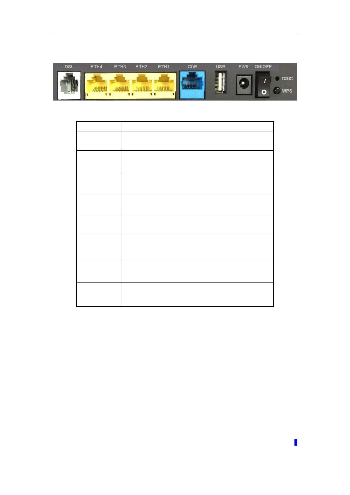
Rear panel
Port
Function
DSL
Connect the device to a DSL telephone jack or splitter
using a RJ-11 telephone cable
ETH1-4
Connect the device to your PC's Ethernet port, or to the
uplink port on user’s hub/switch, using a RJ-45 cable
GbE
Connect the device to user’s PC’s Ethernet port,or to the
uplink port on user’s hub/switch, using a RJ-45 cable
USB
Connect the device to a Printer
PWR
Connect to the supplied power adapter
ON/OFF
Switch it on or off
Reset
ystem reset to factory default
WPS
A convenient way for WPS set.
WLAN VDSL Gateway User Manual
8
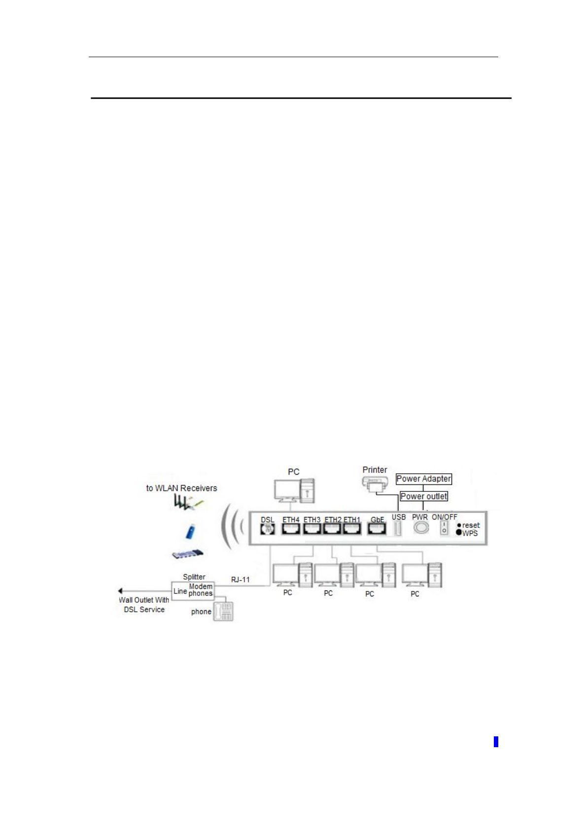
3 Hardware Installation
This chapter shows you how to connect Router. Meanwhile, it introduces the
appropriate environment for the Router and installation instructions.
1. Using a telephone line to connect the DSL port of ROUTER to the MODEM
port of the splitter, and using a other telephone line connect your telephone
to the PHONE port of the splitter, then connect the wall phone jack to the
LINE port of the splitter.
The splitter comes with three connectors as below:
LINE: Connects to a wall phone jack (RJ-11 jack)
MODEM: Connects to the DSL jack of ROUTER
PHONE: Connects to a telephone set
2. Using an Ethernet Cable to connect the LAN port of the ROUTER to your
LAN or a PC with network card installed.
3. Connect the power cable to the PWR connector on ROUTER, then plug in
the AC power adapter to the AC power outlet, and then press the on-off
button.
Notes: Without the splitter and certain situation, transient noise from
telephone can interfere with the operation of the Router, and the
Router may introduce noise to the telephone line. To prevent this
from happening, a small external splitter must be connected to
each telephone.

WLAN VDSL Gateway User Manual
9
4 PC Configuration Guide
4.1 For windows 7
1)Click “Start ->Control Panel->Network and Internet ->View
networks status ->Change adapter settings”
2)Right-click Wireless Network Connection(or Local Area conncection), and
then click Properties.
3)Select Internet Protocol Version 4 (TCP/IPv4), and then clcik Properties.
4)Select Obtain an IP address automatically and Obtain DNS Server
address automatically. Then click OK.
4.2 For Windows 8
1)Move your mouse to the lower right corner and click the Serch icon in the
popus.
2)Go to Apps, type Control Panel in the serche box and press enter.
3)Go to “Control Panel ->lView networks status->Change adapter
settings”
4)Right-click Ethernet,select Properties, then double-click internet protocol
version 4( TCP/IPv4).
5)Select Otain an IP address automatically and Obtain DNS Server address
automatically. Then click OK.
4.3 For windows XP
1) Click “Start” ->Control Panel -> Network and Internet Connection ->
Network Connections”
2) Right-click Wireless Networks Connection (or Local Area
Connection), and then click Properties.
3) Select Internet Protocol (TCP/IP), and then click Properties.
4) Select Otain an IP address automatically and Obtain DNS Server address
automatically. Then click OK.
4.4 For Mac OS X
1) Click the Apple icon on the upper left corner of the screen.
2) Go to “System Preference” ->Network”.
3) Select Airport on the left menu bar, and then click Advanced for wireless
configuration; or select Ethernet for wired configuration,
4) In the Configure IPv4 box under TCP/IP, select Using DHCP.
5) Click Apply to save the settings.
WLAN VDSL Gateway User Manual
10
5 Web-based Management Guide
In order to use the web-based management software it will be necessary to use a
computer that occupies the same subnet as the Router. The simplest way to do this
for many users will be to use DHCP server that is enabled by default on the Router.
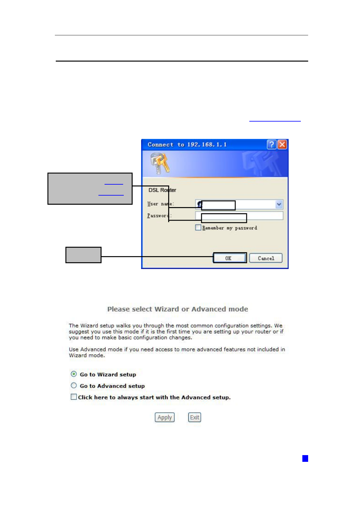
5.1 Setting page
Launch a web browser, such as Internet Explorer, and then use http://192.168.1.1 to
log on to setting page.
After log on, you will see the following screen:
Click OK
Enter username ‘admin’
and password ‘adslroot’
WLAN VDSL Gateway User Manual
11
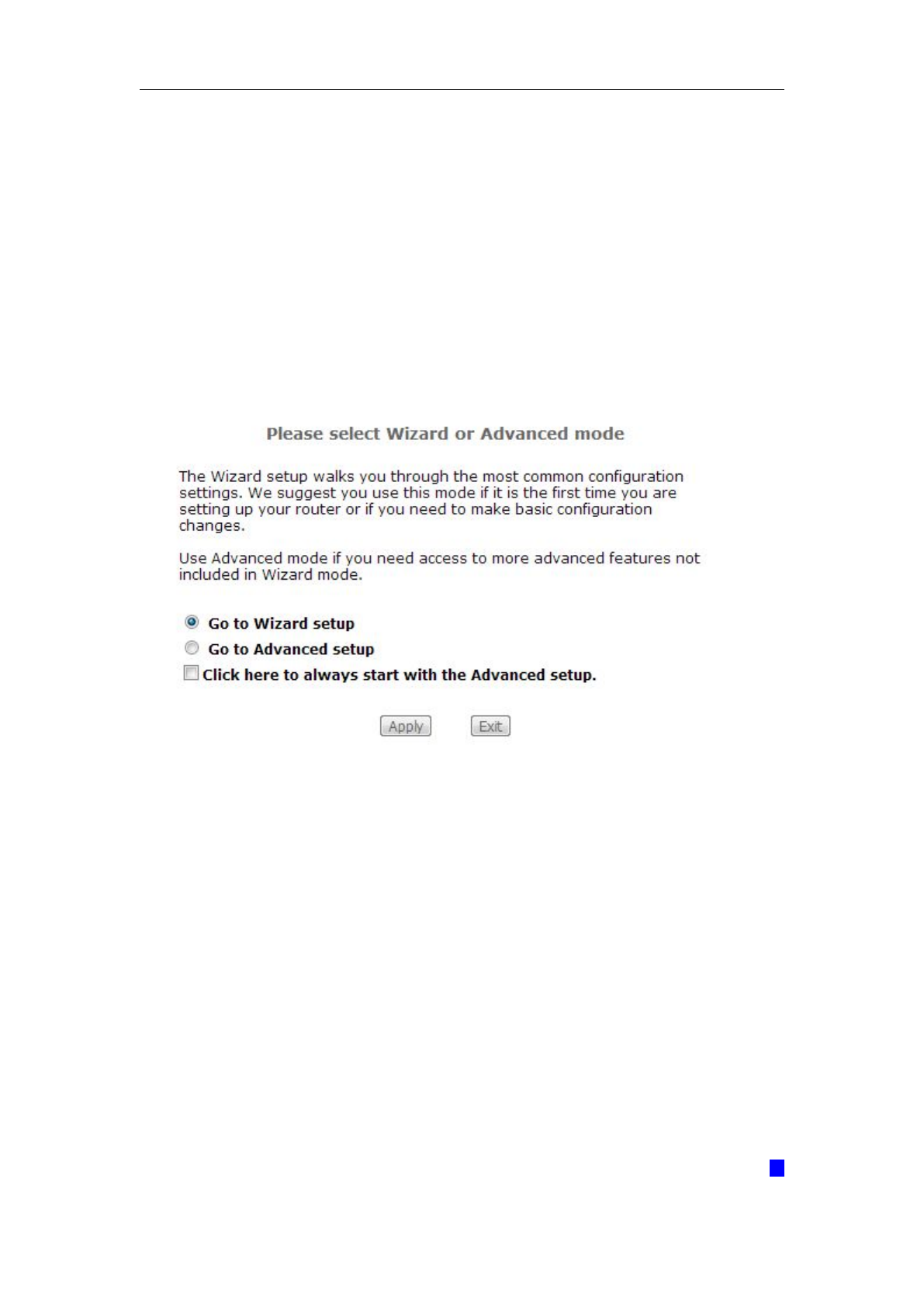
We can select wizard setup or advanced setup mode to setup KW52283, the wizard
set up will guide us for a basic setting, and the advanced setup will guide us to home
page for more detailed setup.
5.2 Internet Access Configuration
The Setup wizard will guide you to configure the DSL router to access Internet via
PPPOE type.
5.2.1 Quick Setup Routing
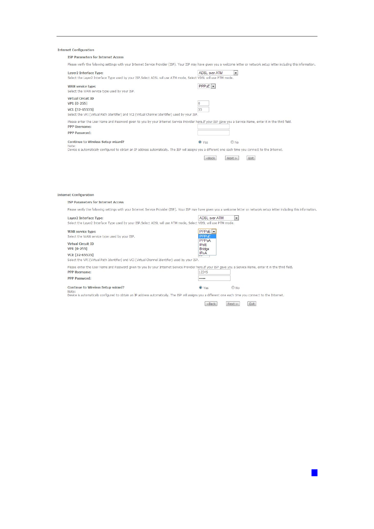
1. Click Quick Setup from the panel and then click Next.
2. Then Select Layer2 Interface ADSL over ATM (ADSL Setup) or PTM (VDSL
Setup).
If your ISP provide ATM mode please input VPI/VCI parameters.
WLAN VDSL Gateway User Manual
12
Then select WAN service and input PPP configuration. Most ISP provides PPP
username and password. Then click Next.
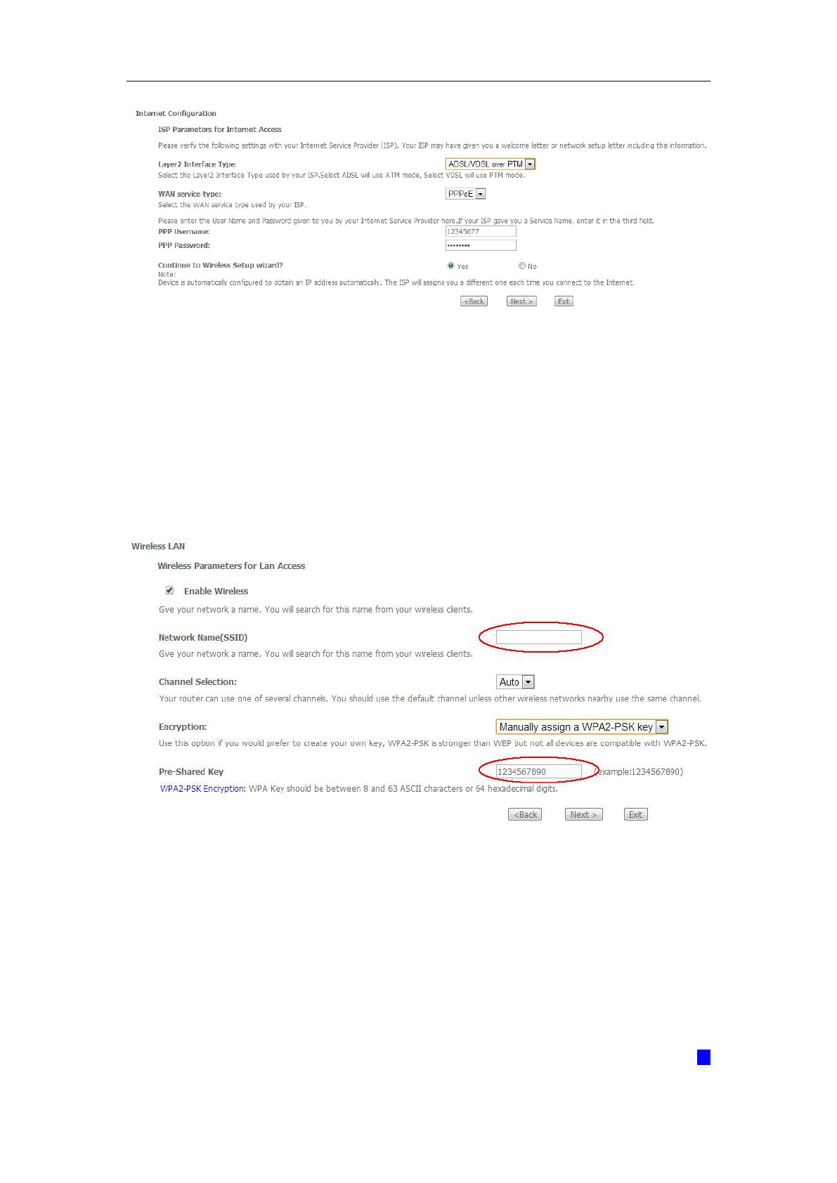
If your ISP provides PTM Mode, please choose ‘ADSL/VDSL over PTM’ in
‘Select Layer2 Interface’. Then select ‘WAN service type’ and input PPP
configuration. Most ISP provides PPP username and password. Then click
Next.
WLAN VDSL Gateway User Manual
13
3. Change SSID known as your wireless name and set a wireless password by
select Encryption, after input your wireless key click Next. If you want to disable
your wireless network, click “Enable Wireless” and let it disabled.
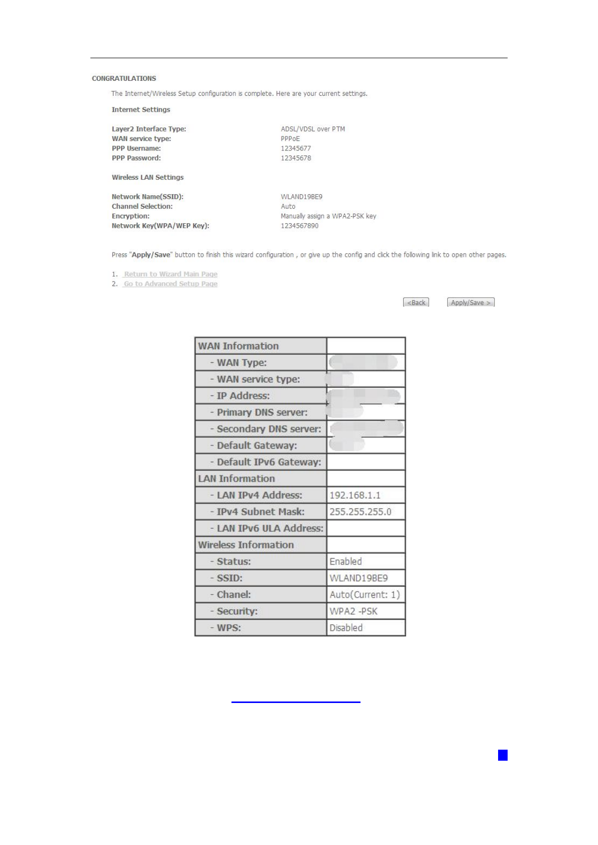
4. Then check your configuration is OK, click Apply/Save.
WLAN VDSL Gateway User Manual
15
5.2.2 ADSL Setup
From home page, you can find Advanced Setup option on the left router
configuration page.
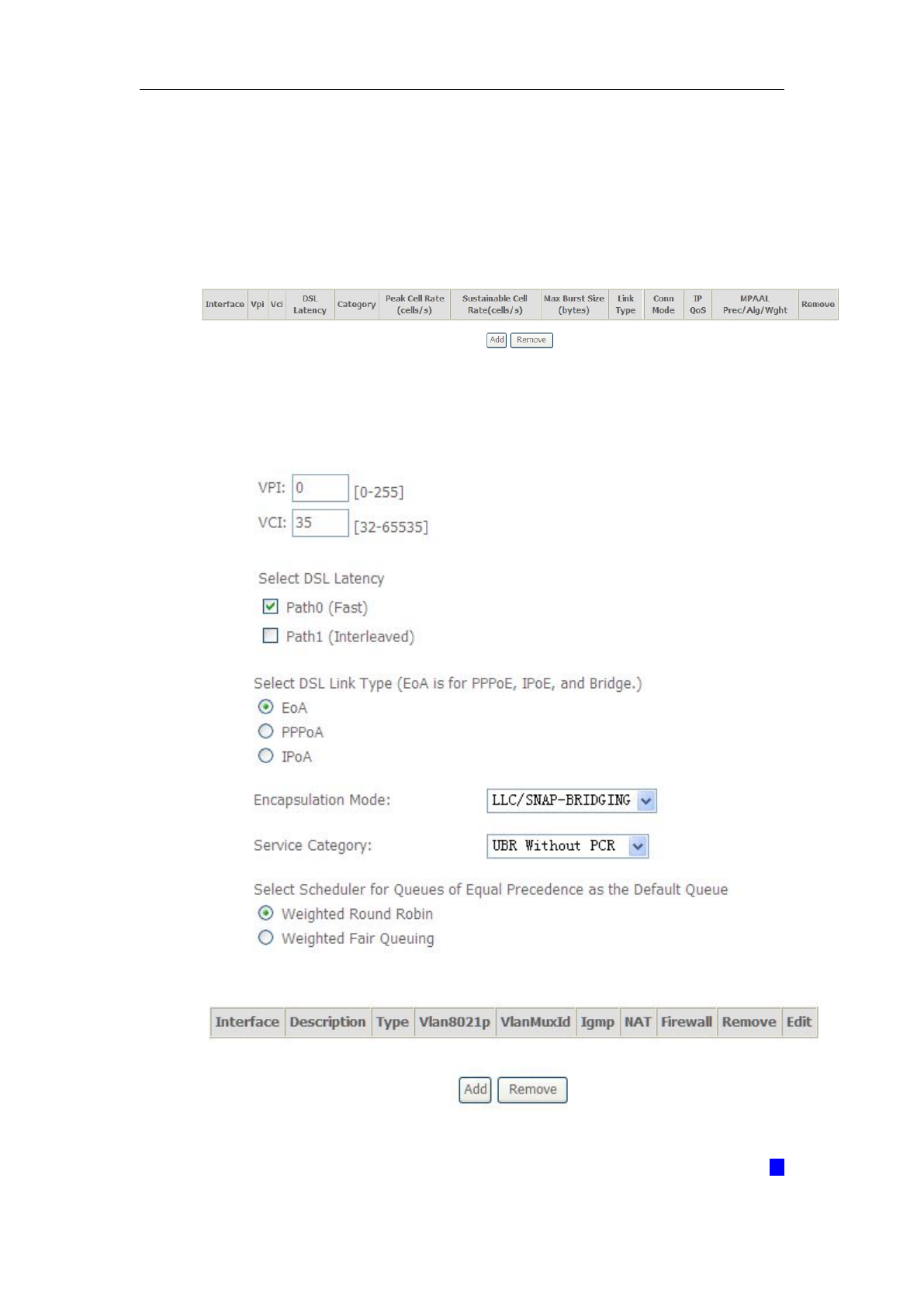
1. From Layer2 Interface, click ATM Interface. you can set it up according to the
following steps. You Choose Add or Remove to configure DSL ATM interfaces.
2. Click Add to configure PVC identifier, select DSL latency and select
connection mode according to your local occasion. After the configuration,
you need to click Apply/Save.
3. Click WAN Service from the left menu.
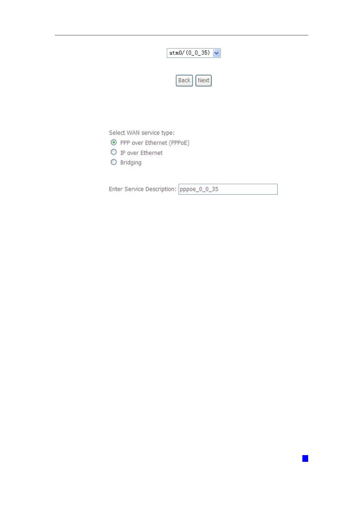
4. Click Add to select a layer 2 interface for this service and then click Next.
WLAN VDSL Gateway User Manual
16
5. Choose WAN service type, just choose PPPoE for example here. You can
enter your own service description here if you want and then click Next.
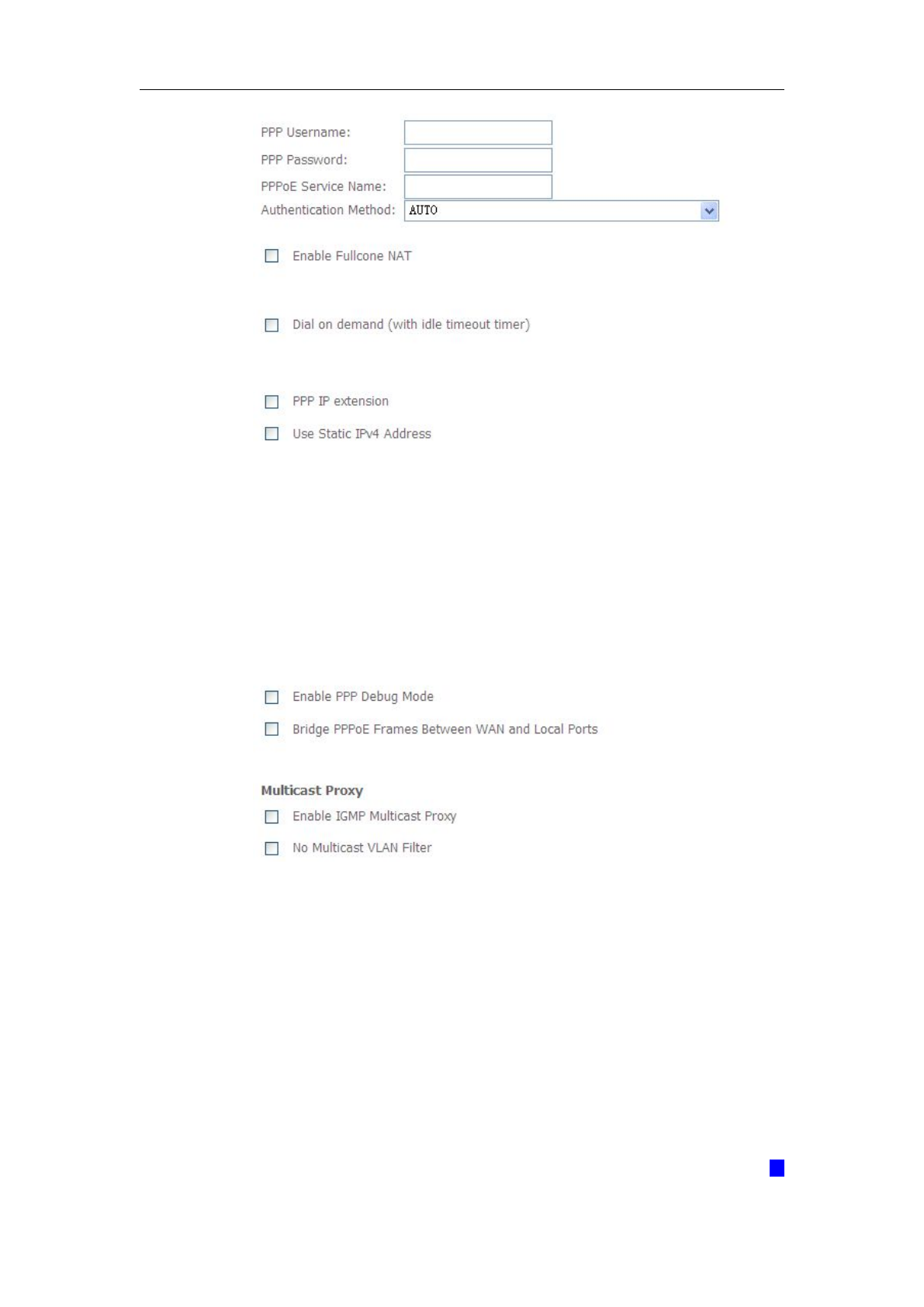
6. Input PPP Username &PPP Password and then click Next. The user
interface allows a maximum of 256 characters in the user name and a
maximum of 32 characters in the password.
WLAN VDSL Gateway User Manual
17
PPPoE service name can be blank unless your Internet Service Provider gives you a
value to enter.
Authentication method is default to Auto. It is recommended that you leave the
Authentication method in Auto, however, you may select PAP or CHAP if necessary.
The default value for MTU (Maximum Transmission Unit) is 1500 for PPPoA and 1492
for PPPoE. Do not change these values unless your ISP asks you to.
Enable FullCone NAT, all requests from the same private IP address and port are
mapped to the same public source IP address and port. Someone on the Internet only

WLAN VDSL Gateway User Manual
18
needs to know the mapping scheme in order to send packets to a device behind the
ADSL router.
The gateway can be configured to disconnect if there is no activity for a specific period
of time by selecting the Dial on demand check box and entering the Inactivity timeout.
The entered value must be between 1 minute and 4320 minutes.
Use Static IPv4 address: If the ISP gave you a static (fixed) IP address, select this
option and enter it in the IP Address field. If the ISP did not give you a static IP
address, clear the Use Static IP Address option. The ISP automatically assigns the
WAN connection an IP address when it connects.
Enable PPP Debug Mode: Select this to turn on the debug mode for the PPP
connection.
Bridge PPPoE Frames Between WAN and Local Ports: In addition to the VDSL
Device's built-in PPPoE client, you can enable this to pass PPPoE through in order
to allow LAN hosts to use PPPoE client software on their computers to connect to
the ISP via the VDSL Device. Each host can have a separate account and a public
WAN IP address. PPPoE pass through is an alternative to NAT for applications
where NAT is not appropriate. Disable PPPoE pass through if you do not need to
allow hosts on the LAN to use PPPoE client software on their computers to connect
to the ISP.
The PPP IP Extension is a special feature deployed by some service providers. Unless
your service provider specifically requires this setup, do not select it. If you need to
select it, the PPP IP Extension supports the following conditions:
It allows only one computer on the LAN.
The public IP address assigned by the remote using the PPP/IPCP
protocol is actually not used on the WAN PPP interface. Instead, it is
forwarded to the computer's LAN interface through DHCP. Only one
system on the LAN can be connected to the remote, since the DHCP
server within the ADSL gateway has only a single IP address to assign
to a LAN device.
NAPT and firewall are disabled when this option is selected.
The gateway becomes the default gateway and DNS server to the
computer through DHCP using the LAN interface IP address.
WLAN VDSL Gateway User Manual
19
The gateway extends the IP subnet at the remote service provider to the
LAN computer. That is, the PC becomes a host belonging to the same
IP subnet.
The ADSL gateway bridges the IP packets between WAN and LAN ports,
unless the packet is addressed to the gateway's LAN IP address.
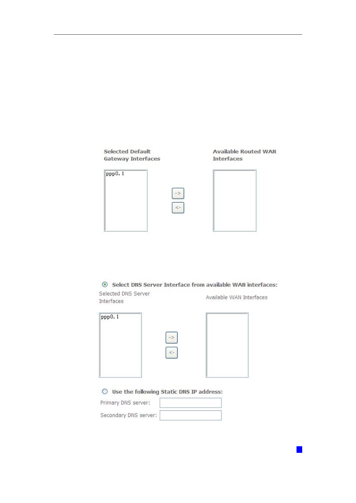
7. Select a preferred wan interface as the system default gateway.
8. Get DNS server information from the selected WAN interface or enter static
DNS server IP addresses. If only a single PVC with IPoA or static MER
protocol is configured, you must enter static DNS server IP addresses.
WLAN VDSL Gateway User Manual
20
9. Make sure that the settings below match the settings provided by your ISP.
Click on the Apply/Save button to save your configurations.
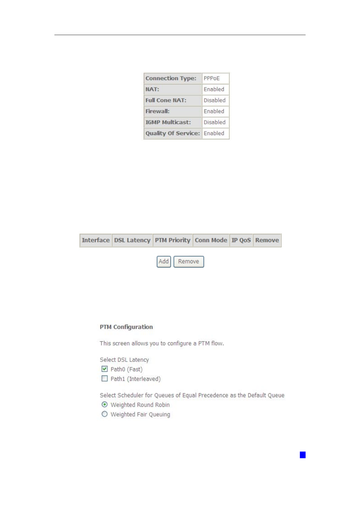
5.2.3 VDSL Setup
From home page, you can find Advanced Setup option on the left router
configuration page.
1. From Layer2 Interface, click PTM Interface. you can set it up according to
the following steps. You Choose Add, or Remove to configure DSL PTM
interfaces.
2. Click Add to configure PTM Priority, select DSL latency and select connection
mode according to your local occasion. After the configuration, you need to click
Apply/Save.
WLAN VDSL Gateway User Manual
21
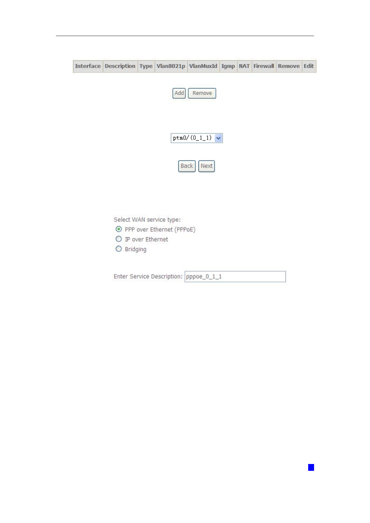
3. Click WAN Service from the left menu.
4. Click Add to select a layer 2 interface for this service and then click Next.
5. Choose WAN service type, just choose PPPoE for example here. You can
enter your own service description here if you want and then click Next.
6. Input PPP Username &PPP Password and then click Next. The user
interface allows a maximum of 256 characters in the user name and a maximum
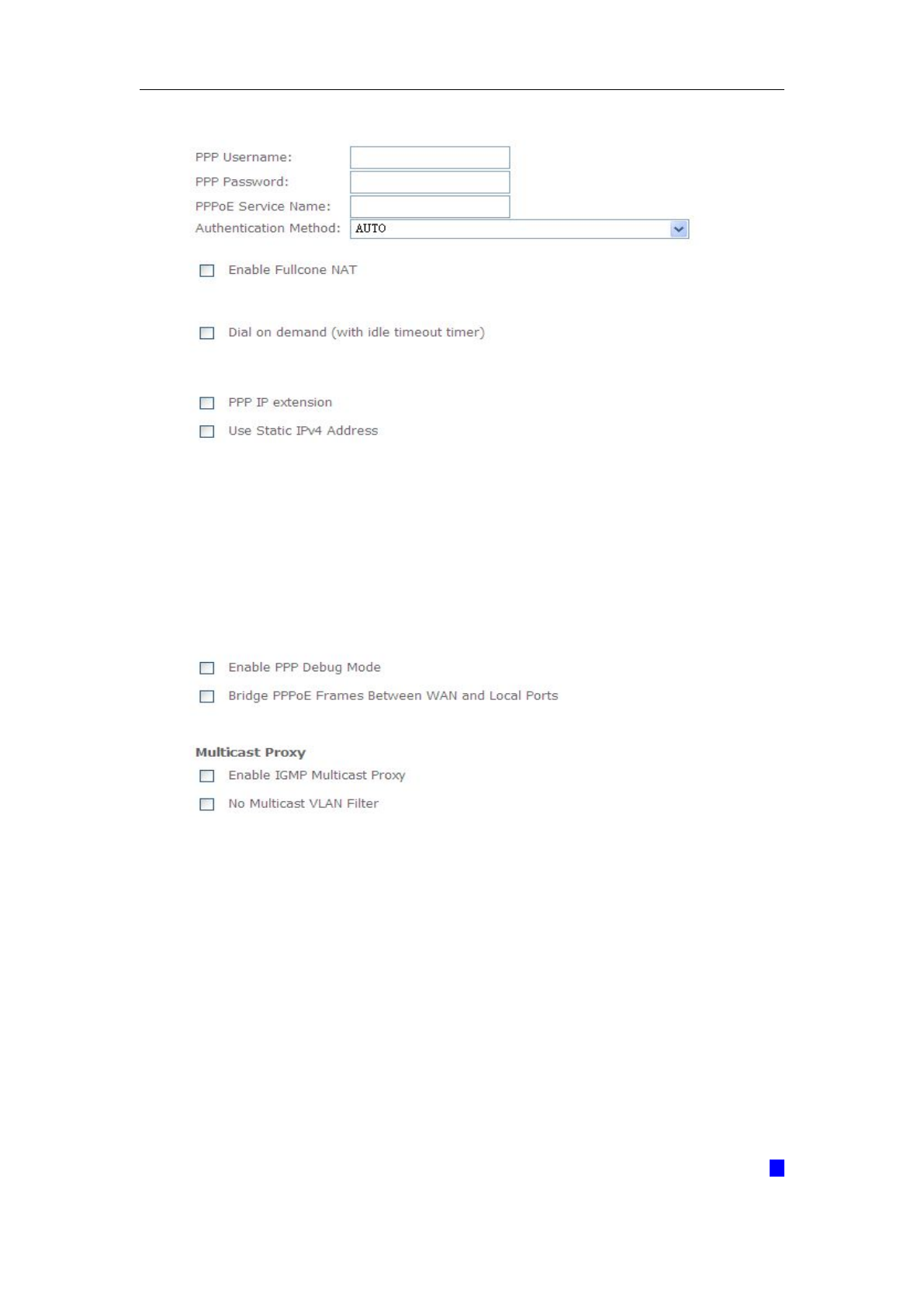
WLAN VDSL Gateway User Manual
22
of 32 characters in the password.
PPPoE service name can be blank unless your Internet Service Provider gives you a
value to enter.
Authentication method is default to Auto. It is recommended that you leave the
Authentication method in Auto, however, you may select PAP or CHAP if necessary.
The default value for MTU (Maximum Transmission Unit) is 1500 for PPPoA and 1492
for PPPoE. Do not change these values unless your ISP asks you to.
Enable FullCone NAT, all requests from the same private IP address and port are
mapped to the same public source IP address and port. Someone on the Internet only
needs to know the mapping scheme in order to send packets to a device behind the
ADSL router.

WLAN VDSL Gateway User Manual
23
The gateway can be configured to disconnect if there is no activity for a specific period
of time by selecting the Dial on demand check box and entering the Inactivity timeout.
The entered value must be between 1 minute and 4320 minutes.
Use Static IPv4 address: If the ISP gave you a static (fixed) IP address, select this
option and enter it in the IP Address field. If the ISP did not give you a static IP
address, clear the Use Static IP Address option. The ISP automatically assigns the
WAN connection an IP address when it connects.
Enable PPP Debug Mode: Select this to turn on the debug mode for the PPP
connection.
Bridge PPPoE Frames Between WAN and Local Ports: In addition to the VDSL
Device's built-in PPPoE client, you can enable this to pass PPPoE through in order
to allow LAN hosts to use PPPoE client software on their computers to connect to
the ISP via the VDSL Device. Each host can have a separate account and a public
WAN IP address. PPPoE pass through is an alternative to NAT for applications
where NAT is not appropriate. Disable PPPoE pass through if you do not need to
allow hosts on the LAN to use PPPoE client software on their computers to connect
to the ISP.
The PPP IP Extension is a special feature deployed by some service providers. Unless
your service provider specifically requires this setup, do not select it. If you need to
select it, the PPP IP Extension supports the following conditions:
It allows only one computer on the LAN.
The public IP address assigned by the remote using the PPP/IPCP
protocol is actually not used on the WAN PPP interface. Instead, it is
forwarded to the computer’s LAN interface through DHCP. Only one
system on the LAN can be connected to the remote, since the DHCP
server within the ADSL gateway has only a single IP address to assign
to a LAN device.
NAPT and firewall are disabled when this option is selected.
The gateway becomes the default gateway and DNS server to the
computer through DHCP using the LAN interface IP address.
WLAN VDSL Gateway User Manual
24
The gateway extends the IP subnet at the remote service provider to the
LAN computer. That is, the PC becomes a host belonging to the same
IP subnet.
The ADSL gateway bridges the IP packets between WAN and LAN ports,
unless the packet is addressed to the gateway’s LAN IP address.
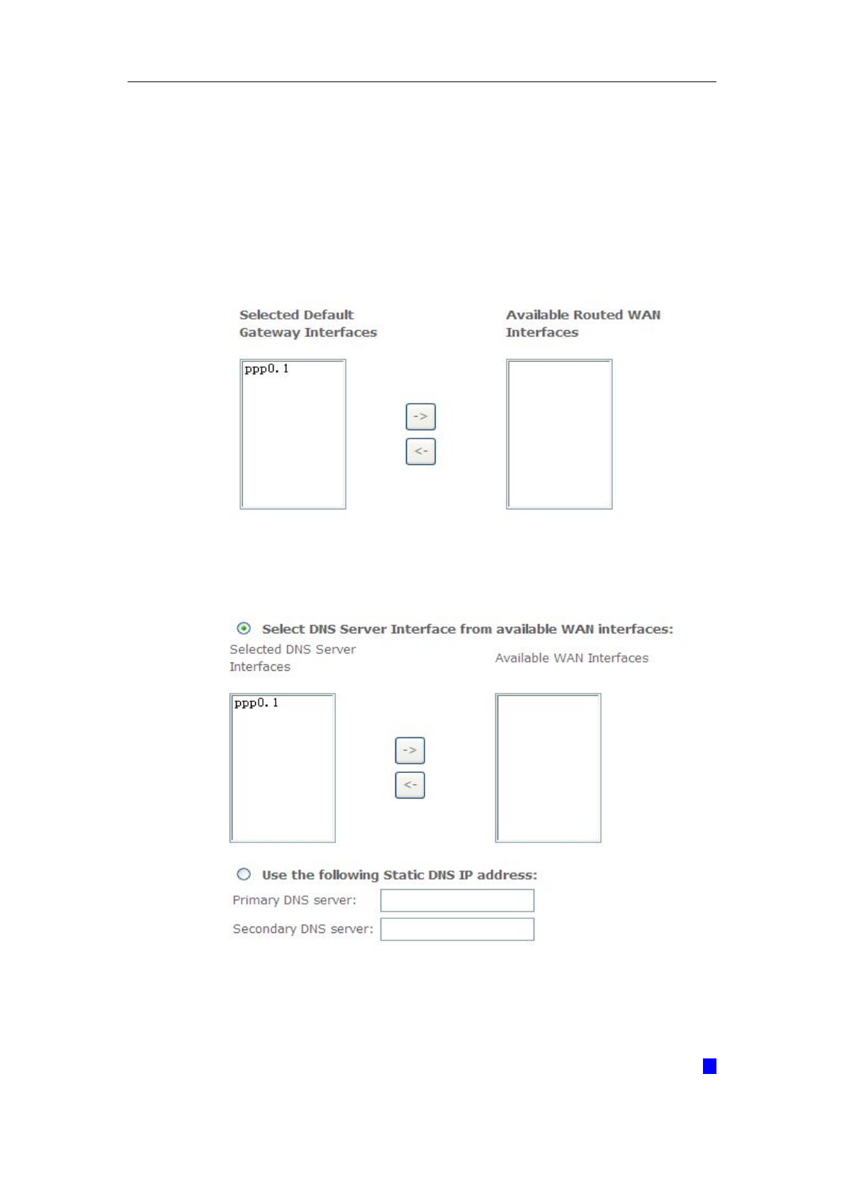
7. Select a preferred wan interface as the system default gateway.
8. Get DNS server information from the selected WAN interface or enter static
DNS server IP addresses. If only a single PVC with IPoA or static MER protocol
is configured, you must enter static DNS server IP addresses.
9. Make sure that the settings below match the settings provided by your ISP.
Click on the Apply/Save button to save your configurations.
WLAN VDSL Gateway User Manual
25
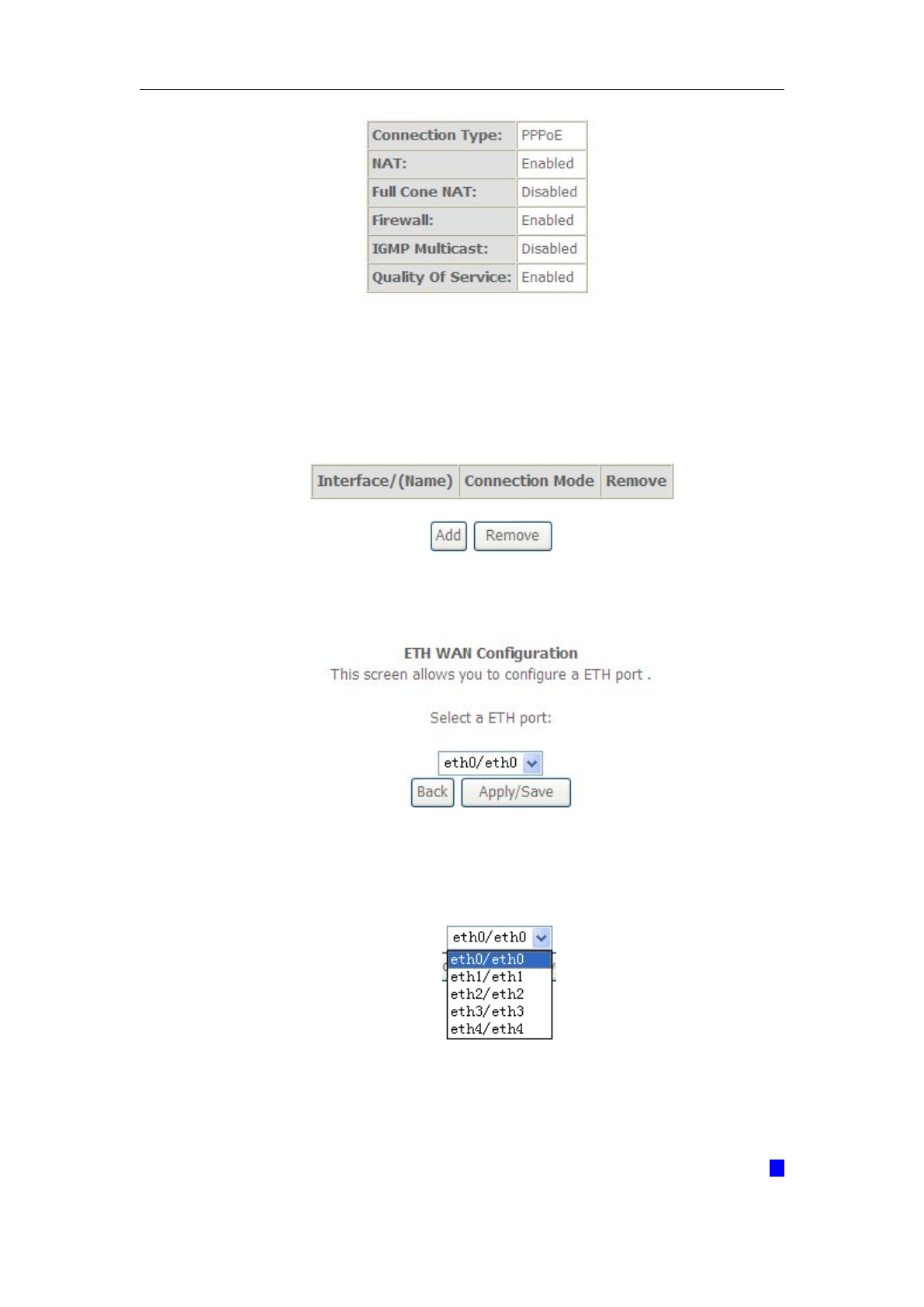
5.2.4 Router Mode Setup
1. From Advanced Setup, click Layer2 Interface and select ETH Interface.
Before you configure ETH WAN interface, you’d better remove all PVC
settings from ATM interface.
2. Click Add and you’ll see the following screen.
3. Select a ETH port as you will. You can select ENET1, ENET2, ENET3 or
ENET4 port as the WAN interface and Default Mode as connection mode.
4. Click Apply/Save and you’ll see the following screen.
WLAN VDSL Gateway User Manual
26
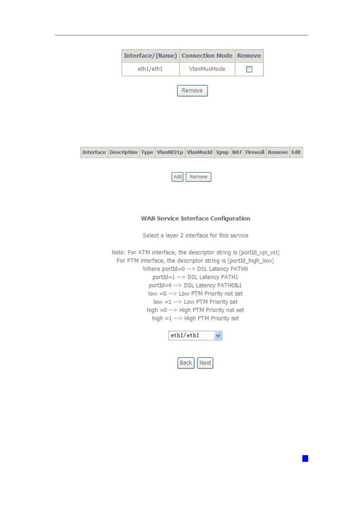
5. From Advanced Setup, click WAN Service to configure a WAN service over
the interface you selected.
6. Click Add and you’ll see the following screen.
7. Click Next and you’ll see the following screen. Select PPPoE as WAN service
type for example. Click Next.

WLAN VDSL Gateway User Manual
27
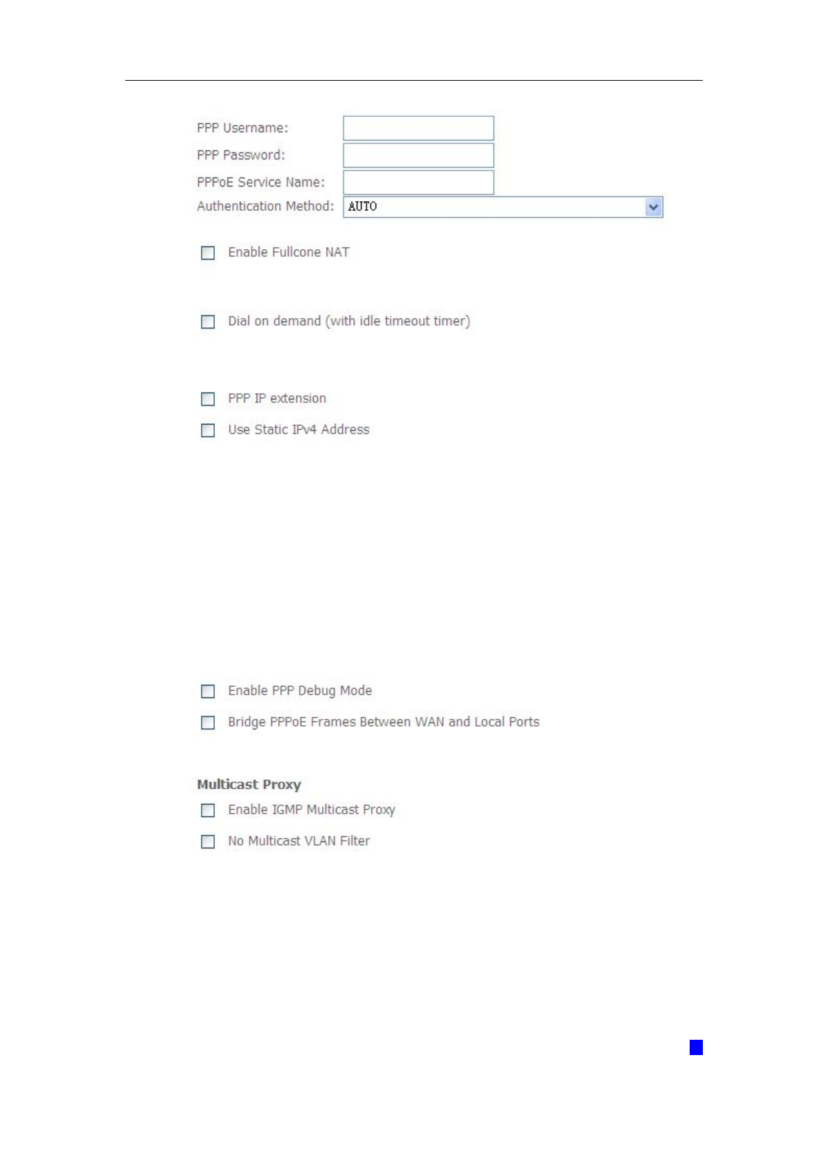
8. Enter the user name and password that your ISP has provided to you. Click
Next.
WLAN VDSL Gateway User Manual
28
PPPoE service name can be blank unless your Internet Service Provider gives you
a value to enter.
Authentication method is default to Auto. It is recommended that you leave the
Authentication method in Auto, however, you may select PAP or CHAP if
necessary. The default value for MTU (Maximum Transmission Unit) is 1500 for

WLAN VDSL Gateway User Manual
29
PPPoA and 1492 for PPPoE. Do not change these values unless your ISP asks you
to.
The gateway can be configured to disconnect if there is no activity for a specific
period of time by selecting the Dial on demand check box and entering the
Inactivity timeout. The entered value must be between 1 minute and 4320
minutes.
Use Static IPv4 address: If the ISP gave you a static (fixed) IP address, select this
option and enter it in the IP Address field. If the ISP did not give you a static IP
address, clear the Use Static IP Address option. The ISP automatically assigns the
WAN connection an IP address when it connects.
Enable PPP Debug Mode: Select this to turn on the debug mode for the PPP
connection.
Bridge PPPoE Frames Between WAN and Local Ports: In addition to the VDSL
Device's built-in PPPoE client, you can enable this to pass PPPoE through in order
to allow LAN hosts to use PPPoE client software on their computers to connect to
the ISP via the VDSL Device. Each host can have a separate account and a public
WAN IP address. PPPoE pass through is an alternative to NAT for applications
where NAT is not appropriate. Disable PPPoE pass through if you do not need to
allow hosts on the LAN to use PPPoE client software on their computers to connect
to the ISP.
The PPP IP Extension is a special feature deployed by some service providers.
Unless your service provider specifically requires this setup, do not select it. If you
need to select it, the PPP IP Extension supports the following conditions:
a) It allows only one computer on the LAN.
b) The public IP address assigned by the remote using the PPP/IPCP
protocol is actually not used on the WAN PPP interface. Instead, it
is forwarded to the computer's LAN interface through DHCP. Only
one system on the LAN can be connected to the remote, since the
DHCP server within the ADSL gateway has only a single IP
address to assign to a LAN device.
c) NAPT and firewall are disabled when this option is selected.
WLAN VDSL Gateway User Manual
30
d) The gateway becomes the default gateway and DNS server to the
computer through DHCP using the LAN interface IP address.
e) The gateway extends the IP subnet at the remote service provider
to the LAN computer. That is, the PC becomes a host belonging to
the same IP subnet.
f) The ADSL gateway bridges the IP packets between WAN and LAN
ports, unless the packet is addressed to the gateway's LAN IP
address.
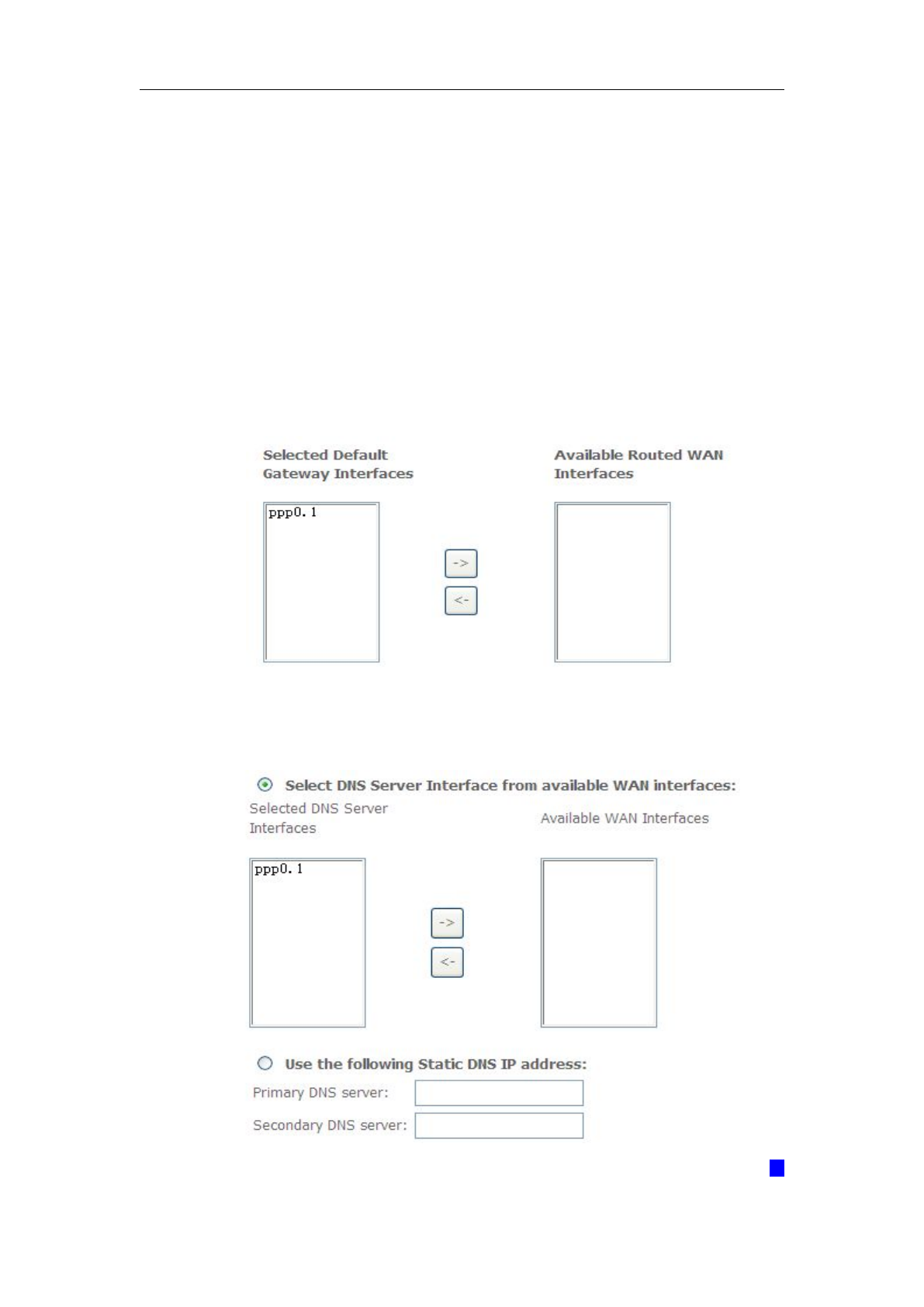
9. Select WAN interface as the system default gateway. Click Next.
10. Get DNS server information from the selected WAN interface or enter static
DNS server IP addresses. Click Next.
WLAN VDSL Gateway User Manual
31
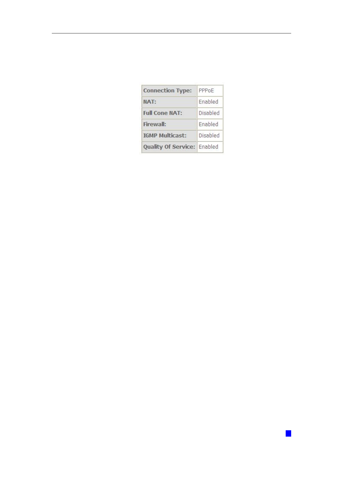
11. Make sure that the settings below match the settings provided by your ISP.
Click on the Apply/Save button to save your configurations and reboot the
ADSL router.
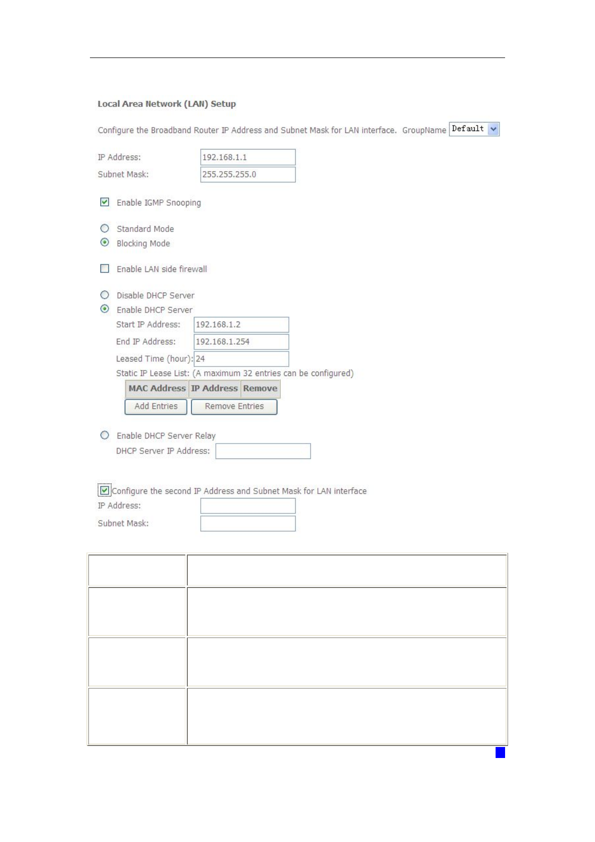
5.2.5 LAN Settings
From LAN, Configure the DSL Router’s IP Address and Subnet Mask for LAN
interface. In this page, you can use DHCP (Dynamic Host Configuration Protocol)
to control the assignment of IP addresses on your local network (LAN only).
KW52283 support IPv4 /IPv6 dual stack.
WLAN VDSL Gateway User Manual
32
5.2.5.1 IPv4 LAN Settings
Item
Description
IP address
This is the IP address that other devices on your local network
will use to connect to the modem.
Subnet mask
This defines the size of your network. The default is
255.255.255.0.
Disable / Enable
DHCP server
The DHCP server assigns an IP addresses from a pre-set pool of
addresses upon request from DHCP client (e.g. your computer).
Do not disable the DHCP server unless you wish to let another

WLAN VDSL Gateway User Manual
33
device handle IP address issuance on the local network.
Start / end IP
address
This is the beginning and ending range for the DHCP server
addresses.
Lease time
The amount of time before the IP address is refreshed by the
DHCP server.
Configure the
second IP
address and...
Use this feature to create a public network on your local LAN,
accessible from the Internet. By assigning an address to this
interface and then statically setting your LAN clients to the same
network, the LAN clients are accessible from the public network
(e.g. FTP or HTTP servers).
WLAN VDSL Gateway User Manual
34
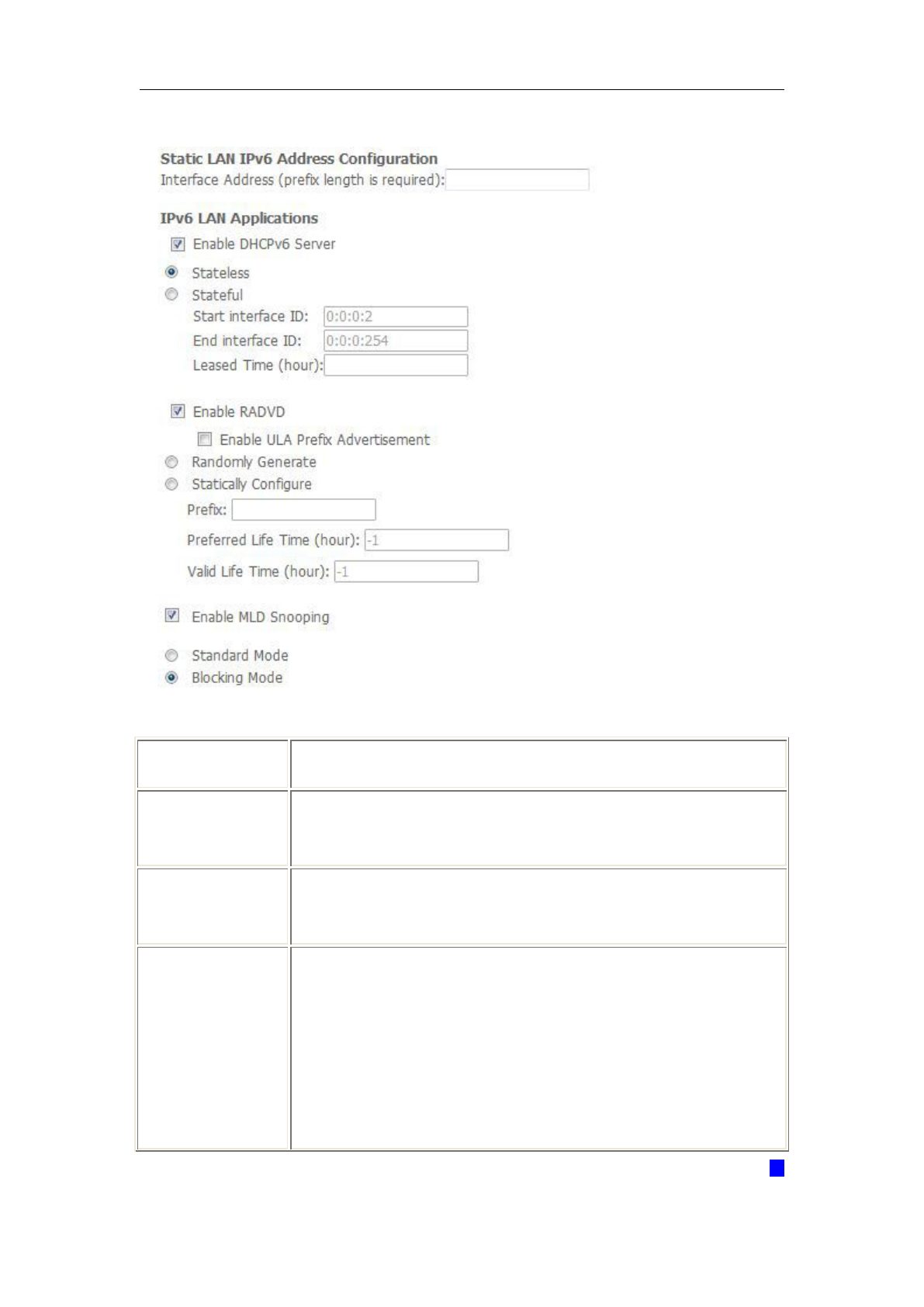
5.2.5.2 IPv6 LAN Settings
Item
Description
IPv6 address
This is the IP address that other devices on your local network
will use to connect to the modem.
Subnet mask
This defines the size of your network. The default is
255.255.255.0.
Enable IGMP
snooping
IGMP Snooping is a method that actually “snoops” or inspects
IGMP traffic on a switch. When enabled, the switch will watch for
IGMP messages passed between a host and a router, and will
add the necessary ports to its multicast table, ensuring that only
the ports that require a given multicast stream actually receive it.
Use standard mode to flood unknown multicast traffic.

WLAN VDSL Gateway User Manual
35
Use blocking mode to discard unknown multicast traffic.
Disable / Enable
DHCP server
The DHCP server assigns an IP addresses from a pre-set pool of
addresses upon request from DHCP client (e.g. your computer).
Do not disable the DHCP server unless you wish to let another
device handle IP address issuance on the local network.
Start / end IP
address
This is the beginning and ending range for the DHCP server
addresses.
Leased time
The amount of time before the IP address is refreshed by the
DHCP server.
Configure the
second IP
address and...
Select this option to let the device use a second IP address on
the LAN interface. You can also use this second IP address to
access the device for management. Enter the LAN IP address of
your device in dotted decimal notation, for example, 10.0.0.1.
Type the subnet mask.
Note: If you want to cancel all modification that you do on the Router, please
select from “ManagementSettingRestore Default Settings” to restore
factory default settings.
WLAN VDSL Gateway User Manual
36
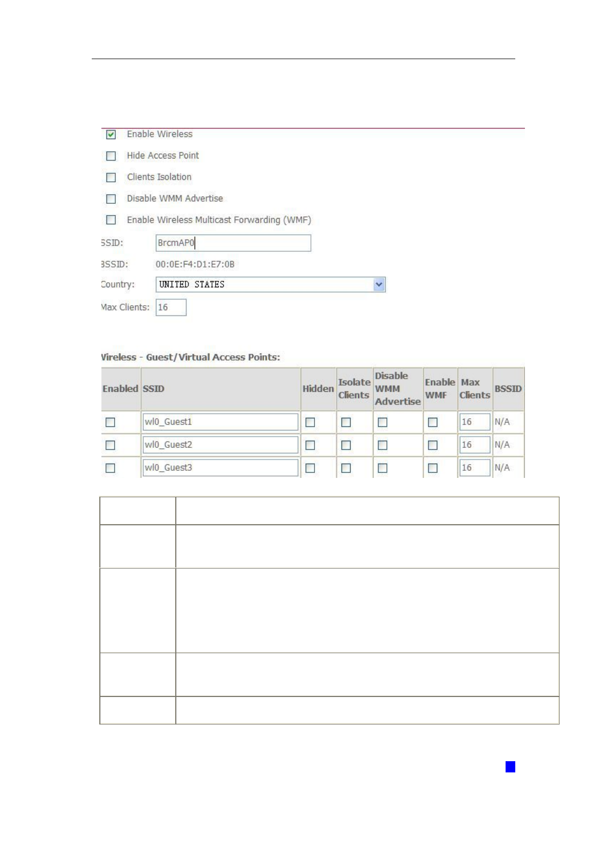
5.3 Wireless setting
5.3.1 Basic
Option
Description
Enable
wireless
A checkbox that enables or disables the wireless LAN interfaces. The default
is to enable wireless communications.
Network
name (SSID)
Enter a name for user’s wireless network here. SSID stands for Service Set
Identifier. This name must be between 1 and 32 characters long. All wireless
clients must either detect the gateway or be configured with the correct SSID to
access the Internet.
BSSID
Displays the gateway's wireless MAC address. (User may need this address
if user is using WDS or multiple gateways.) Click Apply to save changes.
Country
Drop-down menu that allows selection of specific channel.
WLAN VDSL Gateway User Manual
37
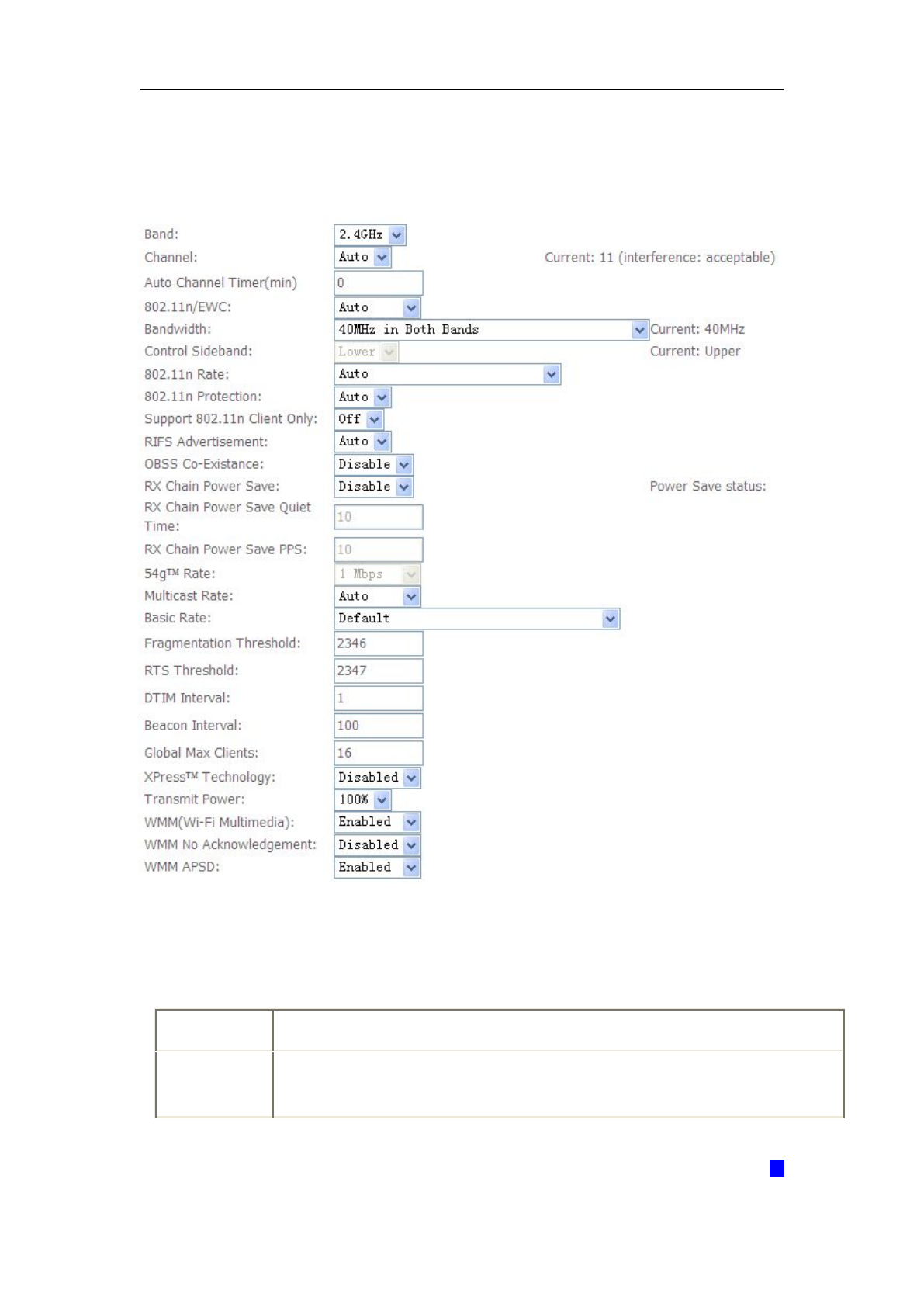
5.3.2 Advanced Settings
This page is where user specifies a number of advanced settings for wireless
communications.
Note: After making any changes, click Apply to save.
Warning: The settings shown above are default settings. Changes made to these
items can cause wireless communication problems.
Field
Description
Band
This is the range of frequencies the gateway will use to communicate with
user’s wireless devices.

WLAN VDSL Gateway User Manual
38
Channel
Drop-down menu that allows selection of specific channel.
54gTM Rate
This drop-down list lets user specify the wireless communication rate, which
can be Auto (uses the highest rate when possible, or else a lower rate) or a
fixed rate between 1 and 54 Mbps.
Multicast rate
This drop-down list lets user specify the wireless communication rate for
multicast packets, which are sent to more than one destination at a time.
The value can be Auto (uses the highest rate when possible, or else a
lower rate) or a fixed rate between 1 and 54 Mbps.
Basic rate
User has the option of supporting all rates listed in Rate above or using the
1-, 2-Mbps rates, which support only older 802.11b implementations.
Fragmentatio
n threshold
A threshold, specified in bytes, that determines whether packets will be
fragmented and at what size. On an 802.11 connection, packets that are larger
the fragmentation threshold are split into smaller units suitable for the circuit
size. Packets smaller than the specified fragmentation threshold value are not
fragmented.
Enter a value between 256 and 2346. If user experience a high packet error
rate, try to increase this value slightly. Setting the fragmentation threshold too
low may result in poor performance.
RTS
threshold
This is number of bytes in the packet size beyond which the gateway
invokes its RTS/CTS (request to send, clear to send) mechanism. Packets
larger than this threshold trigger the RTS/CTS mechanism, while the
gateway transmits smaller packets without using RTS/CTS. The default
setting of 2347, which is the maximum, disables the RTS threshold
mechanism.
DTIM interval
A delivery traffic indication message (DTIM), also known as a beacon, is a
countdown informing wireless clients of the next window for listening to
broadcast and multicast messages. When the gateway has broadcast or
multicast messages for its clients, it sends its next DTIM message with this
DTIM interval value. The clients hear the beacons and awaken as needed
to receive the broadcast and multicast messages.
Beacon
interval
The amount of time (in milliseconds) between beacon transmissions, each
of which identifies the presence of an access point. By default, wireless
clients passively scan all radio channels, listening for beacons coming from
access points. Before a client enters power-save mode, it needs the beacon
interval to determine when to wake up for the next beacon (and learn
whether the access point has any messages for it). User can enter any
value between 1and 65535, but the recommended range is 1 - 1000.
WLAN VDSL Gateway User Manual
39
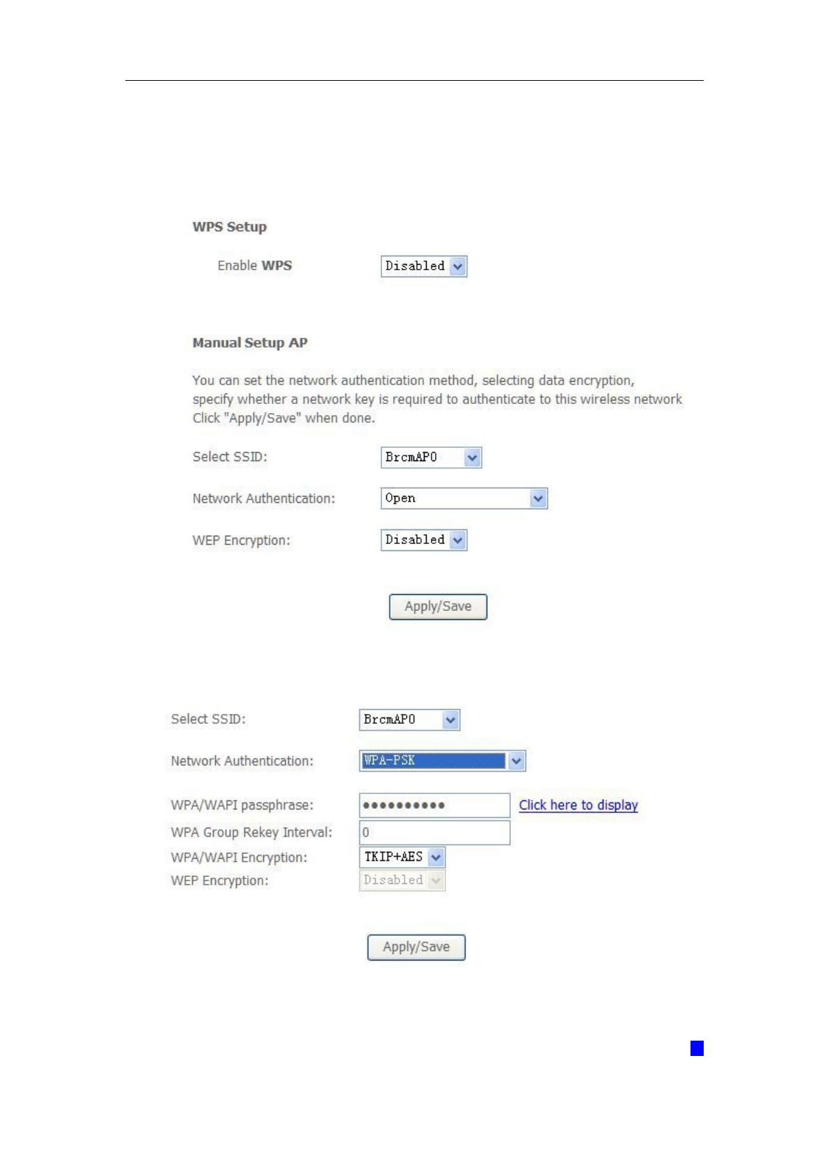
5.3.3 Security
This page allows you to configure security features of the wireless LAN interface.
You may set up configuration manually or through WiFi Protected Setup (WPS)
1. Click Security of Wireless item and you’ll see the following page.
2. Configure WPA2 Pre-shared key as below and click Apply/Save.
3. Enable WPS as below.
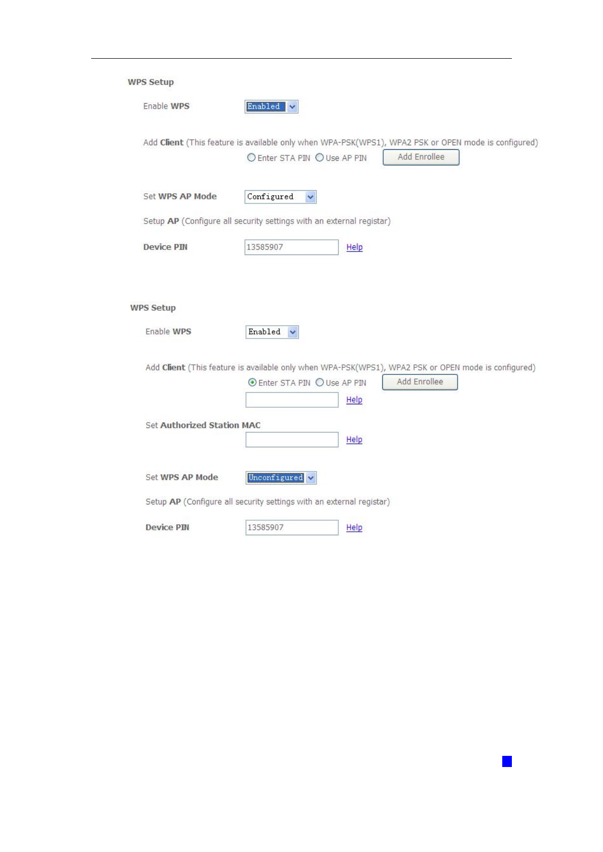
WLAN VDSL Gateway User Manual
40
4. Set WPS AP mode as unconfigured and click Config AP.
5. Set WPS AP mode as configured and click Save/Apply.
6. Now you can use a wireless adaptor with WPS function and the WPS button to
connect to access the Internet.
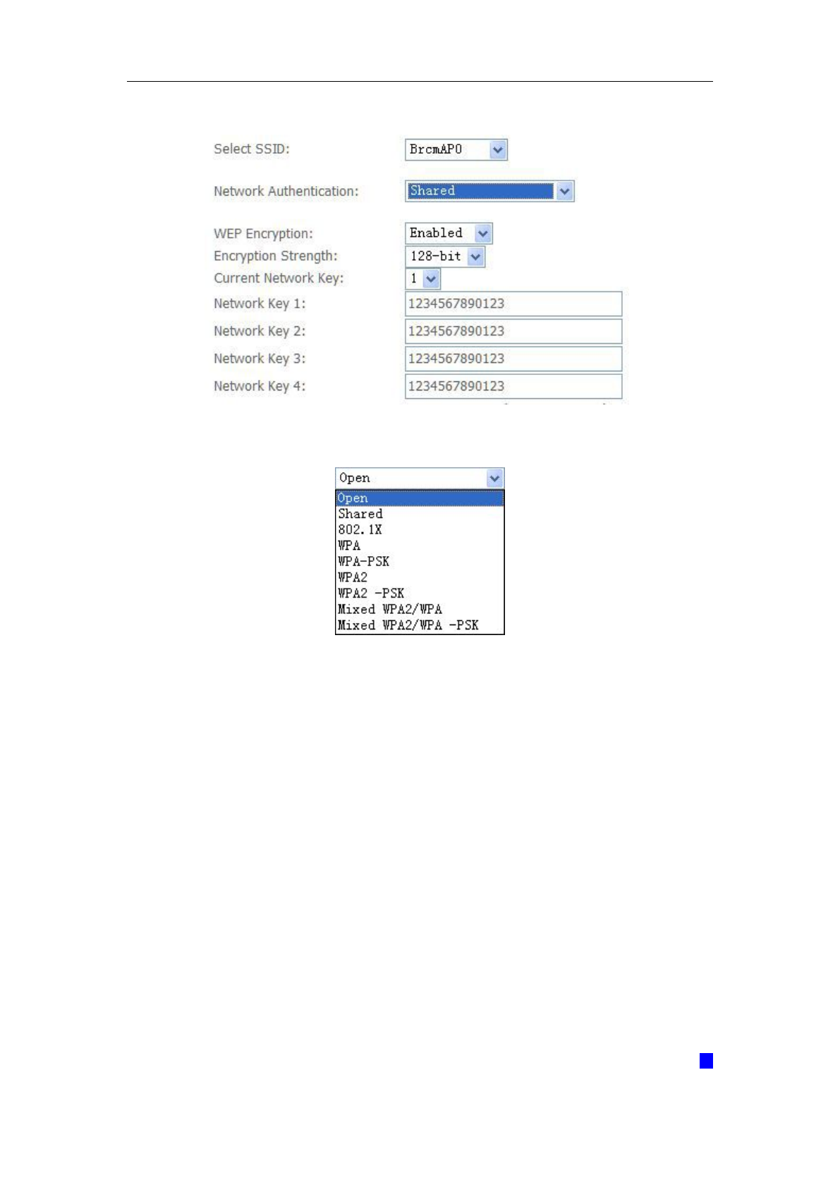
7. To configure security features for the Wireless interface, please open Security
item from Wireless menu. This web page offers nine authentication protocols for
user to secure user’s data while connecting to networks. There are four
selections including Open, Shared, 802.1X,WPA, WPA-PSK, WPA2, WPA2-PSK,
Mixed WPA-WPA2, Mixed WPA-WPA2-PSK. Different item leads different web
page settings. Please read the following information carefully.
The wireless security page allows user to configure the security features of user’s
WLAN VDSL Gateway User Manual
41
wireless network.
There are several security methods to choose from, depending on user’s needs and
the capabilities of user’s wireless machines.
WEP open and WEP shared —WEP is an encryption scheme that is used
to protect user’s wireless data communications. WEP uses a combination
of 64-bit keys or 128-bit keys to provide access control to user’s network
and encryption security for every data transmission. To decode a data
transmission, each wireless client on the network must use an identical
64-bit or 128-bit key. WEP is an older wireless encryption method that is
not as hard to break as the more-recent WPA.
802.1x — In 802.1x (also known as RADIUS), a separate machine called an
authentication server receives a user ID and password. It grants or denies
access based on whether the ID and password match any entries in its
account list. User can optionally enable WEP encryption with this option.
Because it requires a separate machine acting as the authentication server,
802.1x is most often used in business environments.
WPA — WPA is a more recent encryption method that addresses many of
WLAN VDSL Gateway User Manual
42
the weaknesses in WEP. Any client capable of WPA encryption should use
it instead of WEP.
WPA (PSK) — This is WPA encryption combined with a pre-shared key
(PSK), which is a text string known only to the gateway and authorized
wireless clients. The gateway rejects the login if the client's PSK does not
match.
WPA2 — WPA2 is a more advanced encryption method than WPA. Because
it is a more recent standard, some of user’s wireless devices might not be
able to use it.
WPA2 (PSK) — This option uses WPA2 with a pre-shared key.
WPA2 and WPA — This option supports WPA2/WPA encryption for devices
capable of one or the other standard. The gateway automatically detects
whether a particular device can use WPA2 or WPA.
WPA2 AND WPA (PSK) — This has WPA2 or WPA encryption based on
client abilities, as well as a pre-shared key.
After making changes, click Apply to save.
5.4 Management
5.4.1 Remote Access
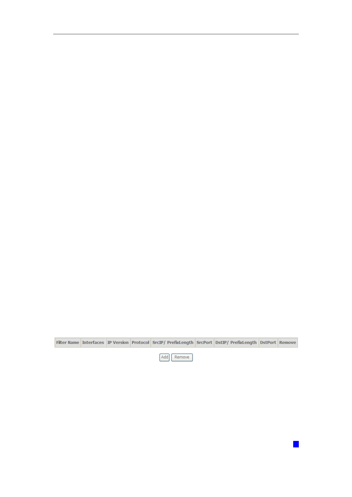
When the firewall is enabled on a WAN or LAN interface, all incoming IP traffic is
BLOCKED. However, some IP traffic can be ACCEPTED by setting up filters.
1. Select Advanced Setup=>Security=>IP Filtering=>Incoming and Choose Add
or Remove to configure incoming IP filters.
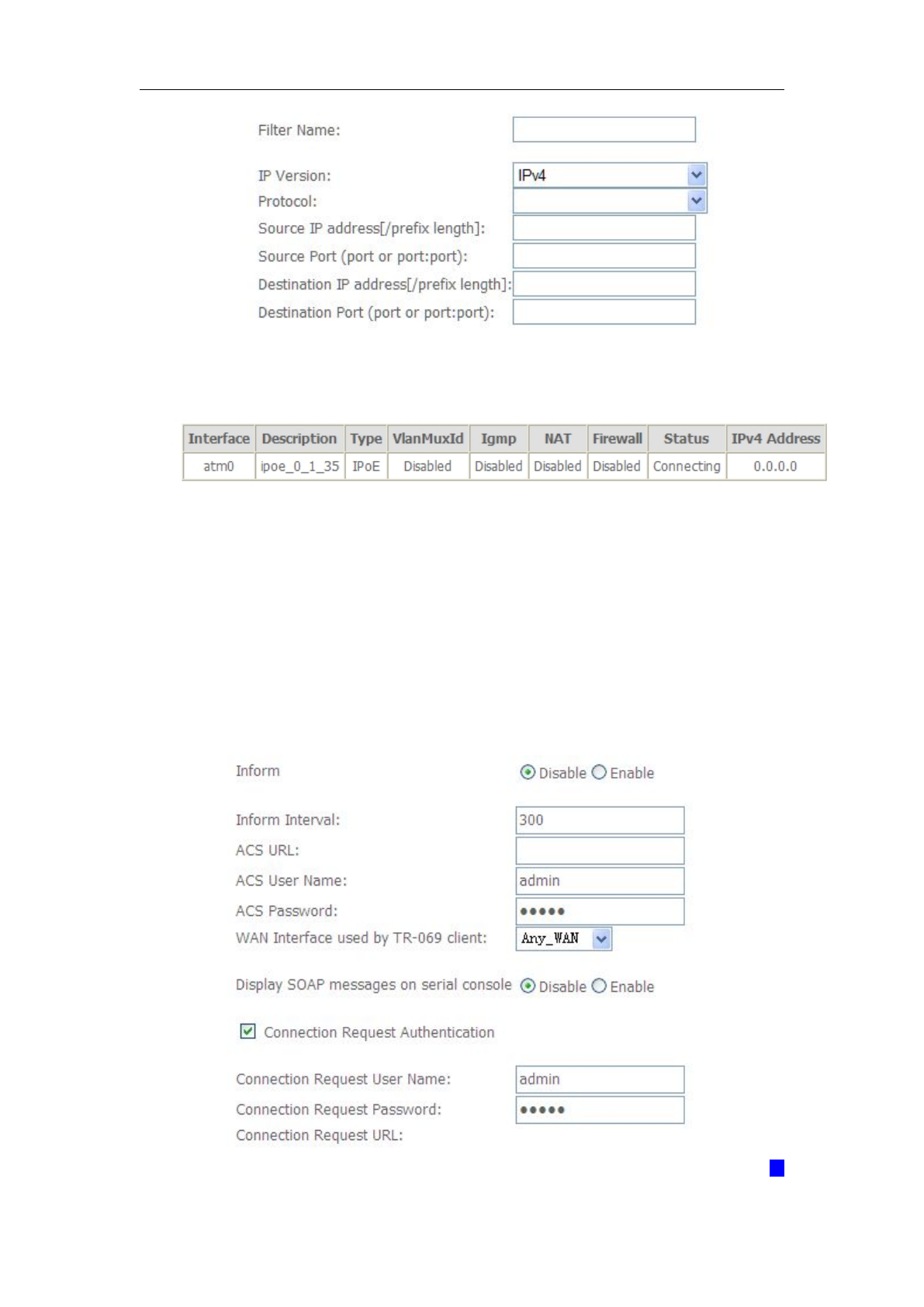
2. Click Add to add rules. If you want to do remote ping test, please select
protocol as ICMP; If you want to do Http or Telnet test, please select protocol as
TCP/UDP. If you want only Http remote access, you can set destination port as
80; If you want only Telnet remote access, you can set destination port as 23; If
you want both, you can set destination port as blank.
WLAN VDSL Gateway User Manual
43
3. Click Apply/Save and select Device Info->WAN. You can see the IP address
of WAN interface.
4. Now you can access the ADSL router remotely using username support
and password support. You can input http://x.x.x.x/ for Http and input telnet
x.x.x.x for Telnet.
5.4.2 TR-069 Client
WAN Management Protocol (TR-069) allows a Auto-Configuration Server (ACS) to
perform auto-configuration, provision, collection, and diagnostics to this device.

WLAN VDSL Gateway User Manual
44
Inform: Whether or not the CPE must periodically send CPE information to Server
using the Inform method call.
Inform Interval: The duration in seconds of the interval for which the CPE MUST
attempt to connect with the ACS and call the Inform method if Inform is enabled.
ACS URL: URL for the CPE to connect to the ACS using the CPE WAN Management
Protocol.
ACS User Name: Username used to authenticate an ACS making a Connection
Request to the CPE.
ACS Password: Password used to authenticate an ACS making a Connection
Request to the CPE. When read, this parameter returns an empty string, regardless of
the actual value.
WAN Interface used by TR-069 client: Remember to choose the interface of PVC
used for TR069
Connection Request User Name: Username used to authenticate the CPE when
making a connection to the ACS using the CPE WAN Management Protocol. This
username is used only for authentication of the CPE.
Connection Request Password: Password used to authenticate the CPE when
making a connection to the ACS using the CPE WAN Management Protocol. This
password is used only for authentication of the CPE.
GetRPCMethods: Used by a CPE or ACS to discover the set of methods supported
by the ACS or CPE it is in communicate with.
WLAN VDSL Gateway User Manual
45
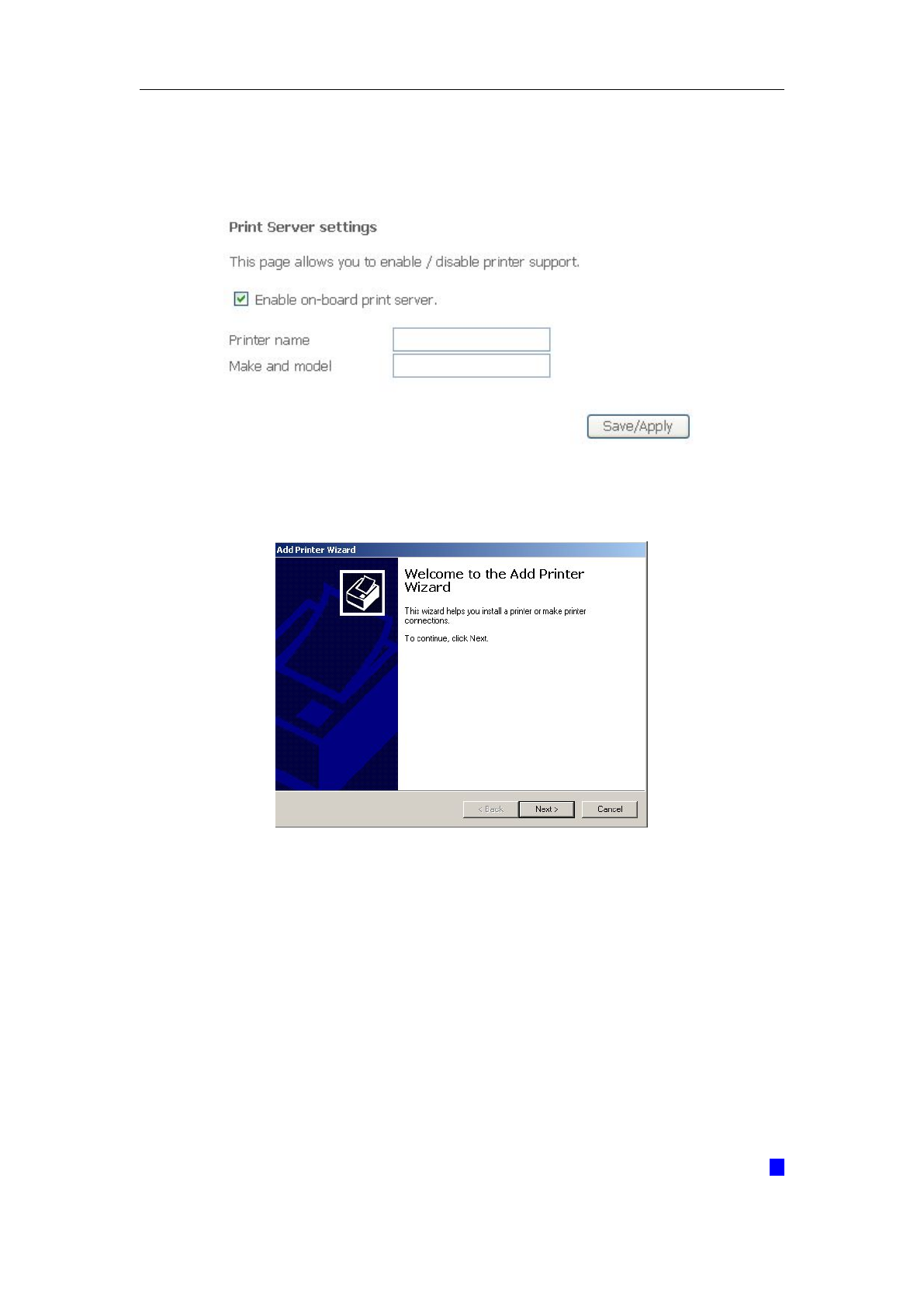
5.4.3 Printer Server Installations
1. Click “Advanced setupPrint Server” and then Check “Enable on-board printer
server” and key in “Printer name”, “Make and model”
2. Click on Add a printer from Control Panel of the Windows computer and click
“Next”.
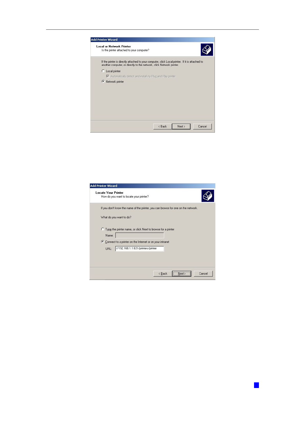
3. Select “Network Printer” and click “Next”.
WLAN VDSL Gateway User Manual
46
4. Select Connect to a printer on the Internet, type
“http://192.168.1.1:631/printers/printer” and click “Next”. The printer name
“Printer” must be the same name entered in the ADSL router “print server
setting” as in step 1.
5. Select driver file directory on CD-ROM or in your hard disk and click “OK”.
6. Choose “Yes” or “No” for default printer setting and click “Next”.
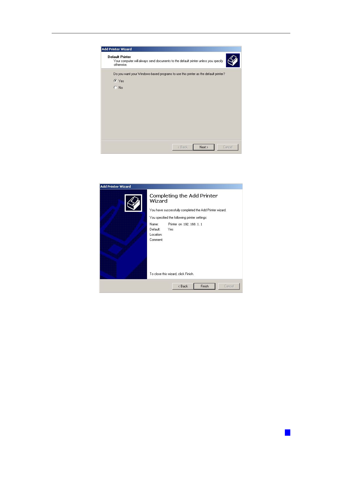
WLAN VDSL Gateway User Manual
47
7. Click “Finish”.
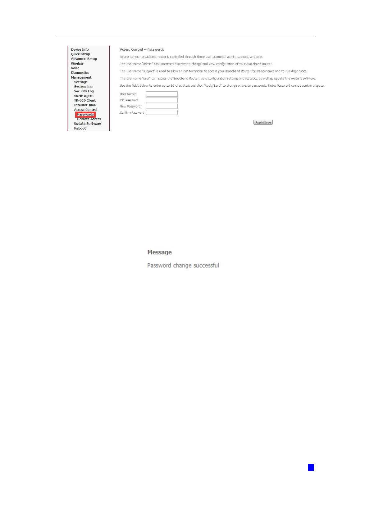
5.4.4 Access Control
Access Control will let you change the password that you need to login in the router’s
setting page.
1. Select Passwords from Management->Access Control.
WLAN VDSL Gateway User Manual
48
2. Type the user name in the User Name. There are 3 user name has different
power to manage the router. Each of them has been shown in the screen;
3. Type in the Old Password;
4. Type in the New Password and Confirm Password. These two blanks should be
typed in the same words;
5. Click Apply/Save;
6. You will see the following screen.
Note: If you want to cancel all modification that you do on the Router, please
select from “MaintenanceRebootRestore factory default settings.
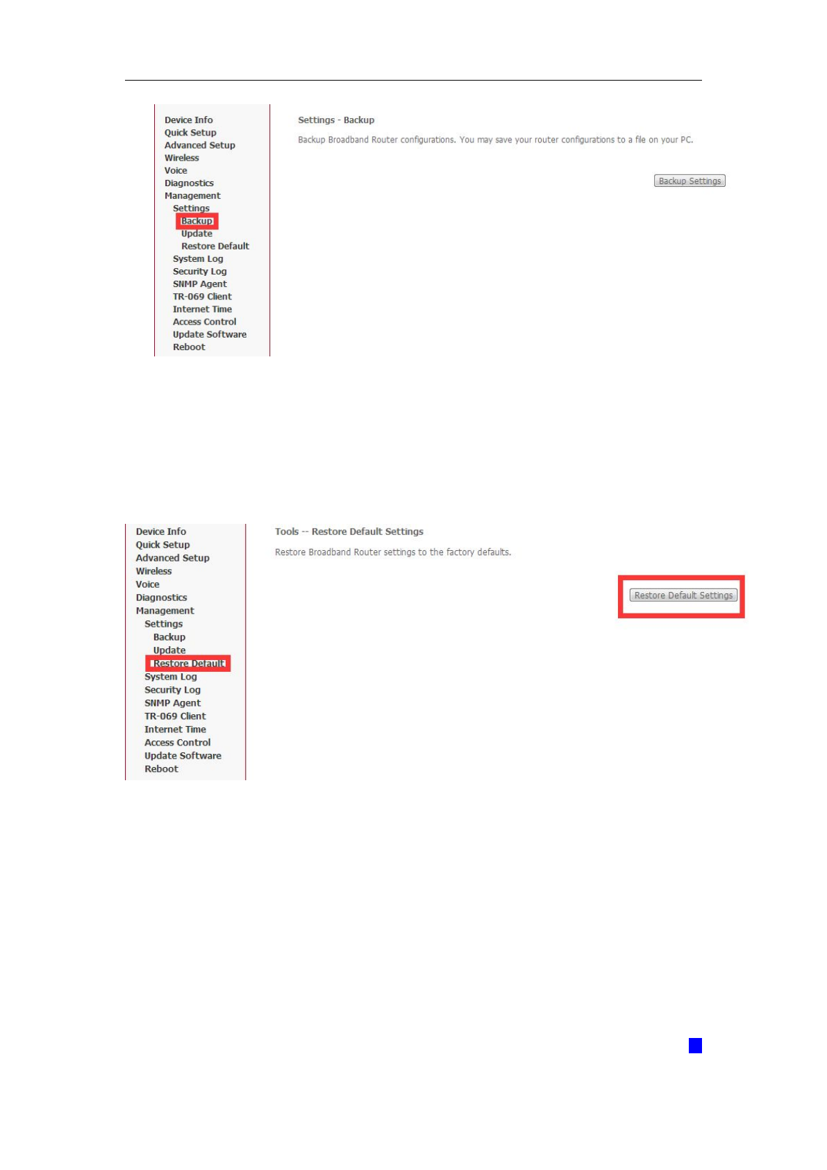
5.4.5 Backup
1. You can choose Backup in the Management->Settings. Click Backup Settings
to storage your settings at present.
2. Choose the path where your settings want to set in.
WLAN VDSL Gateway User Manual
49
Note: If you want to cancel all modification that you do on the Router, please
select from “MaintenanceRebootRestore factory default settings.
5.4.6 Restore Default.
1. You can release the ball-point after about 5 seconds.
2. You can go to Restore Default at Management and click Restore Default Settings
and wait until the router reboot it again.
Note: After you have then completed the full-reset. Your VDSL router will
now have its factory default settings. IP address will be 192.168.1.1 and the
subnet mask will be 255.255.255.0. User name will be admin and password
will be admin.
WLAN VDSL Gateway User Manual
50
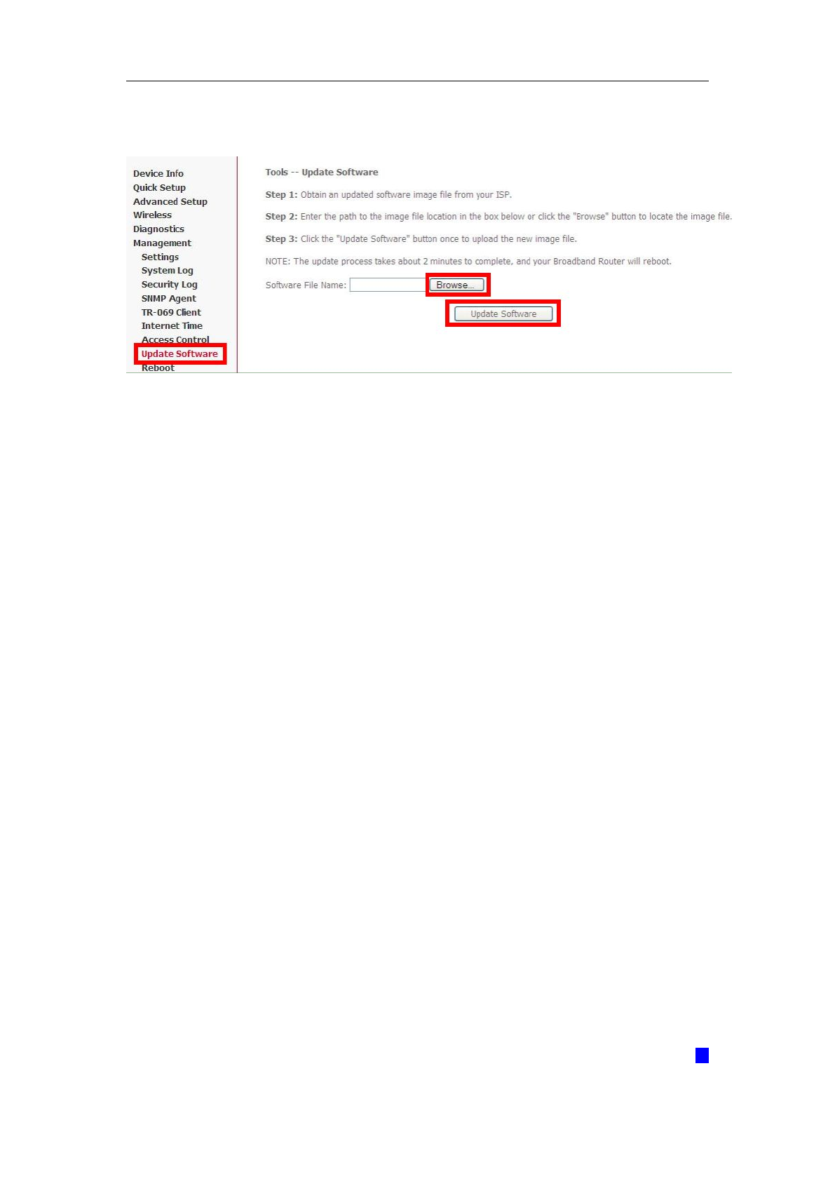
5.4.7 Update
1. You can update your firmware at Update Software in Management.
Note: Be sure that the firmware you want to update is the same product
model as yours. Do not turn off the power when the updating is not
finished!When it finished, you can’t turn back to the default version unless
you have the previous firmware!

WLAN VDSL Gateway User Manual
51
Appendix: Frequent Asked Questions
This chapter offers some suggestions to solve problems you might encounter. The
potential problems are divided into 3 categories: Power, Hardware Connections, and
LEDs; Device Access and Login; Internet Access.
1. Power, Hardware Connections, and LEDs
None of the LEDs are on when power on the Kasda router.
Please make sure what you use is the power adaptor attached with the VDSL
router package and checks the connection between the AC power and VDSL
router.
DSL LED does not turn on after connect telephone line.
Please make sure what you use is the standard telephone line (as attached with
the package), make sure the line is connected correctly and check whether there
is poor contact at each interface. Wait for 30 seconds to allow the VDSL router
establishes connection with you VDSL operator.
DSL LED is in the circulation of slow-flashing and fast-flashing after
connecting telephone line.
This situation means the VDSL router is in the status of failing to establish
connection with Central Office. Please check carefully and confirm whether the
VDSL router has been installed correctly.
LAN LED does not turn on after connect Ethernet cable.
Please make sure Ethernet cable is connected hub/PC and VDSL router correctly.
Then please make sure the PC/hub have been power on.
Please make sure that you use parallel network cable to connect UpLink port of
hub, or use parallel network cable to connect PC. If connect normal port of hub
(not UpLink port), you must use cross-cable. Please make sure that your network
cables meet the networking requirements above.

WLAN VDSL Gateway User Manual
52
2. Device Access and Login
I forgot the IP address for the VDSL Router.
1. The default IP address is 192.168.1.1.
2. If you changed the IP address and have forgotten it, you might get the IP
address of the Kasda Router by looking up the IP address of the default
gatewayyou’re your computer. To do this in most Windows computers, click
Start >Run, enter cmd, and then enter ipconfig. The IP address of the
Default Gateway might be the IP address of the Kasda Router (it depends
on the network), so enter this IP address in your Internet browser.
3. If this does not work, you have to reset the device to its factory defaults.
I forgot the password.
1. The default password is password.
2. If this does not work, you have to reset the device to its factory defaults.
I cannot see or access the Login screen in the web configurator.
1. Make sure you are using the correct IP address.
The default IP address is 192.168.1.1.
If you changed the IP address (Section 5.2.5 on page 32), use the new
IP address.
If you changed the IP address and have forgotten it, see the Frequent
Asked Questions for I forgot the IP address for the VDSL Router.
Make sure you are using the correct IP address.
2. Check the hardware connections, and make sure the LEDs are behaving as
expected.
3. Make sure your Internet browser does not block pop-up windows.
4. Make sure your computer is in the same subnet as the Router.
If there is a DHCP server on your network, make sure your computer is
using a dynamic IP address.
If there is no DHCP server on your network, make sure your computer’s
IP address is in the same subnet as the Kasda Router.
5. Reset the device to its factory defaults and reboot it again.
My PC is unable to connect to the wireless connection.
Please make sure that all devices communicating with the device must use the
same channel (and use the same SSID). Otherwise your PC will not find the
wireless Router.

WLAN VDSL Gateway User Manual
53
3. Internet Access
My PC cannot access the Internet
First check whether PC can ping the interface Ethernet IP address of this product
successfully (default value is 192.168.1.1) by using ping application. If ping
application fails, please check the connection of Ethernet cable and check
whether the states of LEDs are in gear.
If the PC uses private IP address that is set manually (non-registered legal IP
address), please check:
1. Whether IP address of the PC gateway is legal IP address. Otherwise please
use the right gateway, or set the PC to Obtain an IP address automatically.
2. Please confirm the validity of DNS server appointed to the PC with VDSL
operator. Otherwise please use the right DNS, or set the PC to Obtain an IP
address automatically.
3. Please make sure you have set the NAT rules and convert private IP address
to legal IP address. IP address range of the PC that you specify should meet
the setting range in NAT rules.
4. Central Office equipment may have problem.
5. The country or the wireless network type you selected is wrong.
My PC cannot browse Internet web page.
Please make sure DNS server appointed to the PC is correct. You can use ping
application program to test whether the PC can connect to the DNS server of the
VDSL operator.
Initialization of the PVC connection failed.
Be sure that cable is connected properly from the DSL port to the wall jack. The
DSL LED on the front panel of the VDSL router should be on. Check that your VPI,
VCI, type of encapsulation and type of multiplexing setting are the same as what
you collected from your service provider, Re-configure VDSL router and reboot it.
If you still cannot work it out, you may need to verify these variables with the
service provider.
If the cause is not given above, please contact your local service
provider!