Kenetics Innovations SR14ABC Short Range RFID Reader Module User Manual SR14 ABC CSCRW TechnicalManual V1 0
Kenetics Innovations Pte Ltd Short Range RFID Reader Module SR14 ABC CSCRW TechnicalManual V1 0
User Manual

Kenetics Innovations Pte Ltd
SR14+ABC Transit Reader
CSC-RW Technical Manual
Document Number: SR14+ABC-TEC-0001
Version: 1.0
Date: 2009-01-06
Prepared by Reviewed by
Name Seah Chian Jiunn Ow Khiam Beng
Signature
Date 2009-01-06 2009-01-06

Table of Contents
Section 1:
Amendment Record.............................................. 1
1.1 Change Log ....................................................................................... 2
Section 2:
Introduction ............................................................ 3
2.1 Purpose................................................................................................ 3
2.2 Abbreviations ..................................................................................... 3
2.3 Terminology ........................................................................................ 3
Section 3:
Hardware Specification......................................... 4
3.1 General Hardware Specifications .................................................. 4
3.2 Radio Frequency Interface Specification ..................................... 5
3.3 Physical Dimensions Specifications................................................. 6
3.4 Electrical Specifications.................................................................. 10
3.5 Field Strength Profile of CSC-RW ................................................... 11
Section 4:
Operational Precautions ..................................... 12
4.1 General Safety Instructions ............................................................ 12
4.2 Installation ......................................................................................... 13
4.3 Diagnostic Status Indicators........................................................... 13
Section 5:
Compliance Statement....................................... 14
Table of Figures
Figure 3.1 General Hardware Specifications........................................................ 4
Figure 3.2 On-board IO Ports Specification......................................................... 4
Figure 3.3 Radio Frequency Interface Specification ............................................ 5
Figure 3.4 Physical Dimensions Specifications ................................................... 6
Figure 3.5 SR14+ABC Reader general outlines................................................... 7
Figure 3.6 SR14+ABC Reader Mechanical Dimensions...................................... 8
Figure 3.7 SR14+ABC Reader Antenna Stackup................................................. 8
Figure 3.8 10 pin connector pin assignment......................................................... 9
Figure 3.9 Electrical Specifications................................................................... 10
Figure 3.10 Magnetic Field Strength profile of SR14+ABC Reader................ 11
Figure 4.1 Installation Recommendations.......................................................... 13

SR14+ABC CSC-RW T
ECHNICAL
M
ANUAL
V
ERSION
1.0 C
ONFIDENTIAL
1
Section 1: Amendment Record
S/N
By Description Date Version
1 Seah Draft Release 2008-11-20
0.1
2 Seah Update for Final Design Documentation 2009-01-06
1.0

SR14+ABC CSC-RW T
ECHNICAL
M
ANUAL
V
ERSION
1.0 C
ONFIDENTIAL
2
1.1 Change Log
Version 0.1
−
Initial release.
−
Values documented in this draft document may not be finalized.
Version 1.0
- Update for final design documentation

SR14+ABC CSC-RW T
ECHNICAL
M
ANUAL
V
ERSION
1.0 C
ONFIDENTIAL
3
Section 2: Introduction
2.1 Purpose
The purpose of this document is to document the hardware specification of
SR14+ABC reader. SR14+ABC reader is a contact-less smart reader, designed for
automatic fare collection purpose.
2.2 Abbreviations
CSC-RW Contact-less Smart Card Reader Writer, use interchangeably
with SR14+ABC
RF Radio Frequency
2.3 Terminology
Main Board Control board of SR14+ABC Reader
Antenna Board Antenna of SR14+ABC Reader
SR14+ABC CSC-RW T
ECHNICAL
M
ANUAL
V
ERSION
1.0 C
ONFIDENTIAL
4
Section 3: Hardware Specification
3.1 General Hardware Specifications
Embedded Processors / Memory
CPU Types Dual CPU Architecture, 1 RF CPU & 1 Application CPU.
Secure Application Module ( SAM )
Number of SAMs 4 x SAM Slots
RF Specifications
Operating
Frequency 13.56 MHz (+/- 50 ppm)
RF Output Power Up to 0.7 Watt typical.
Protocols
Supported ISO 14443-A, B & C
Reading Range Memory Cards: up to 10cm
CPU Cards: up to 8.5cm
Number of
Outputs 2 UFL RF Outputs, Multiplexed and Alternating
Figure 3.1 General Hardware Specifications
On Board Ports
10 Pin, 2.54mm Pitch
Power In 12VDC, RS232, RS485/TTL
Mini-USB USB Device
Physical Specifications
Dimensions 67 x 104 x 18 mm
Weight 200 Grams +/- 20 grams
Antenna Type
Antenna 1 x Shielded with Ferrite / Spacer Backed, Stackable
Figure 3.2 On-board IO Ports Specification

SR14+ABC CSC-RW T
ECHNICAL
M
ANUAL
V
ERSION
1.0 C
ONFIDENTIAL
5
3.2 Radio Frequency Interface Specification
Specification of Radio Frequency Interface
RF Protocol Supported ISO 14443-A, B & C
Card Supported All ISO14443-X contactless cards
Maximum
Communication Range Logic Card: Up to 10cm
Microprocessor Card: Up to 8.5cm
Operating Frequency 13.56MHz
RF Output Power Up to 0.7 Watt Typical
RF Connector Type U.FL
Figure 3.3 Radio Frequency Interface Specification

SR14+ABC CSC-RW T
ECHNICAL
M
ANUAL
V
ERSION
1.0 C
ONFIDENTIAL
6
3.3 Physical Dimensions Specifications
Physical Dimension Specifications
Connectors • 10 pin, 2.54mm pitch right angled, connector
• Mini-USB connector
Dimensions Control Board with Antenna: 67 x 104 x 18 mm
Material PCBA FR4 Board
Antenna Separate PCB Antenna
Cable Length (between
PCBs ) Approx. 10cm
Operating Temperature -10°C to + 70°C (0% - 95% RH, non-condensing )
Storage Temperature -20°C to + 85°C (0% - 95% RH, non-condensing)
Special Treatment Selective Conformal Coating
Reference Figure Figure 3.6
Figure 3.4 Physical Dimensions Specifications
SR14+ABC CSC-RW T
ECHNICAL
M
ANUAL
V
ERSION
1.0 C
ONFIDENTIAL
7
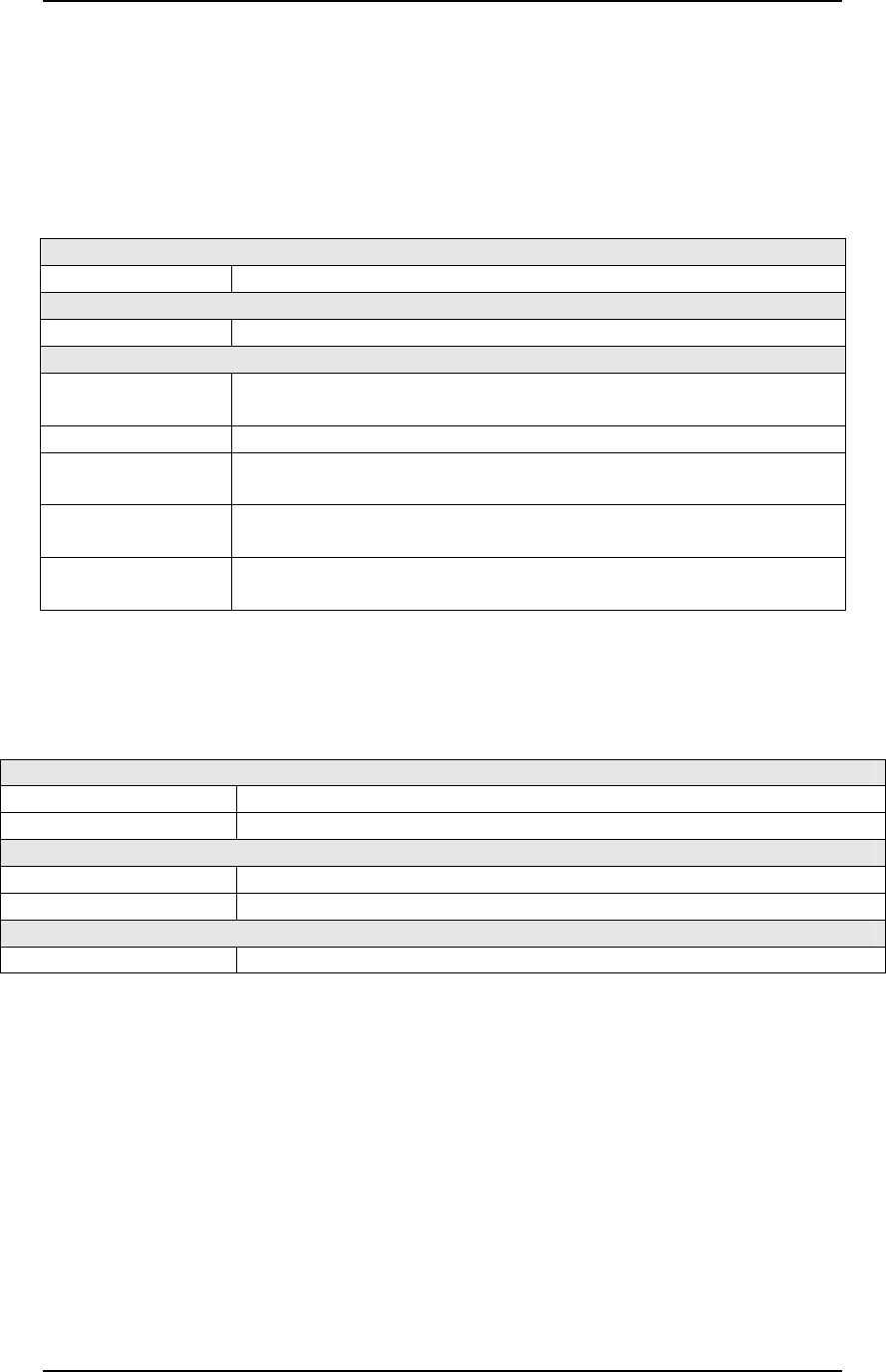
Figure 3.5 SR14+ABC Reader general outlines
1
1
Stand-off and screws are not part of DCPS, and deliverables.
J1
SR14+ABC Main Board
SR14+ABC Antenna Board
Antenna cable
Antenna cable
104 mm
67 mm 67 mm >
20 mm
SR14+ABC Main Board and Antenna Board assembled together
SR14+ABC CSC-RW T
ECHNICAL
M
ANUAL
V
ERSION
1.0 C
ONFIDENTIAL
8
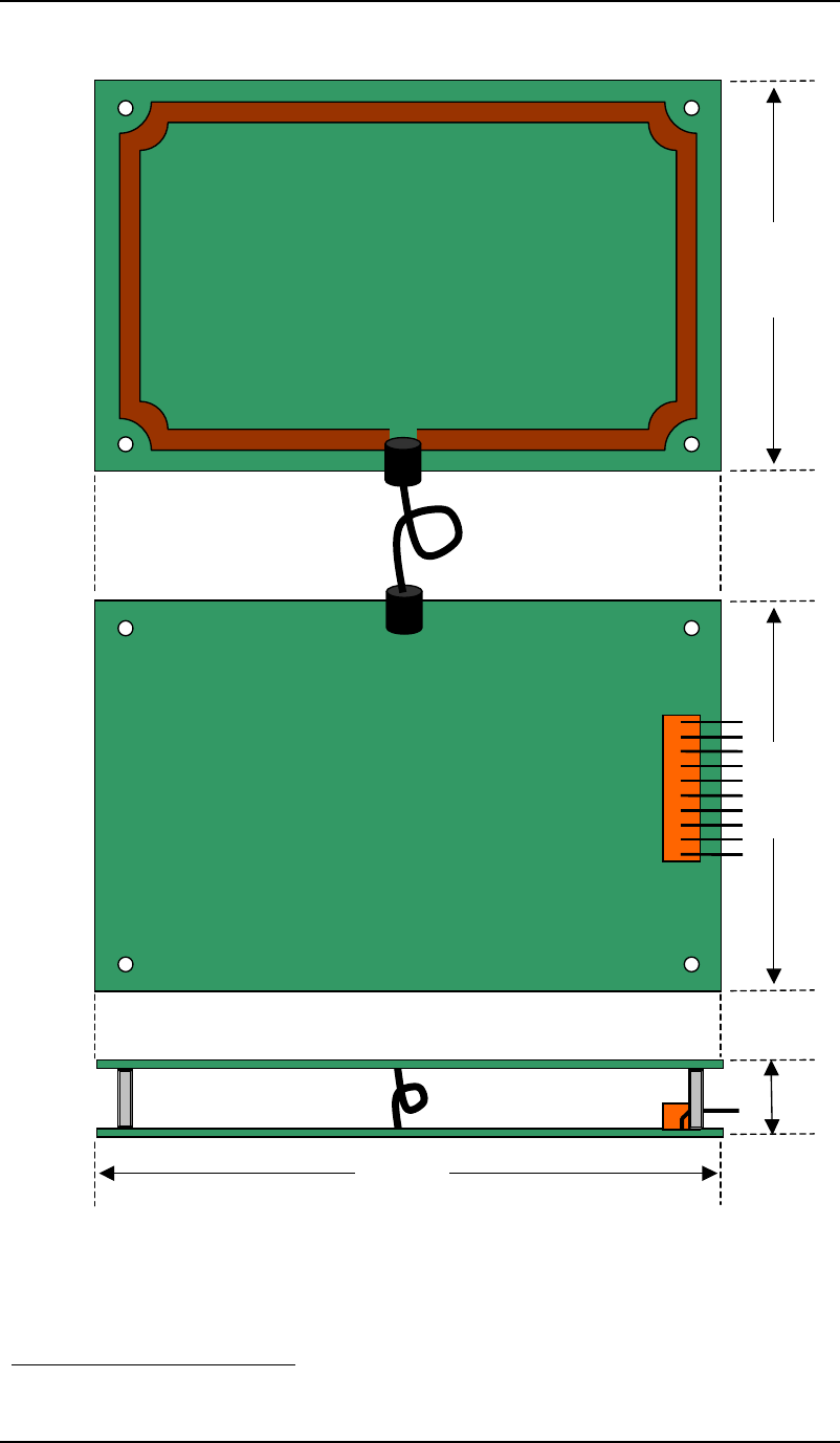
Figure 3.6 SR14+ABC Reader Mechanical Dimensions
Figure 3.7 SR14+ABC Reader Antenna Stackup
SR14+ABC CSC-RW T
ECHNICAL
M
ANUAL
V
ERSION
1.0 C
ONFIDENTIAL
9
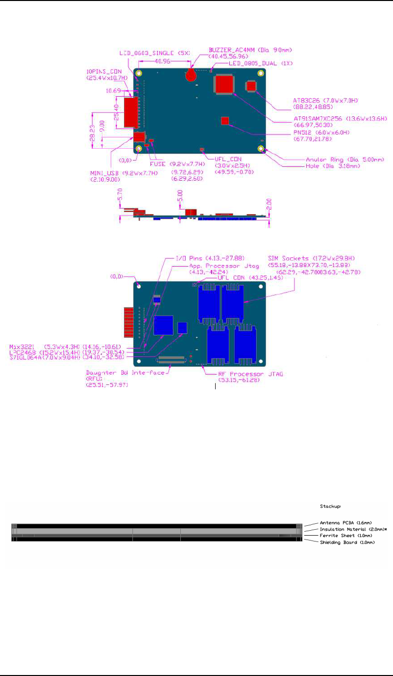
10-pin connector – Pin No. Signals
1 Reset Control SHDN
2 Power GND
3 Power Power Supply (+12V)
4 RX-
5 RX+ (TTL-Rx)
6 TX-
7
RS485/TTL
TX+(TTL-Tx)
8 TXD
9 Signal Ground
10
RS232
RXD
Figure 3.8 10 pin connector pin assignment
The reader can be reset by in input voltage above 3 volts on pin 1 of the main
connector - SHDN. Any high pulse longer than 500ms will trigger the hardware reset.
Pin 1
Pin 10

SR14+ABC CSC-RW T
ECHNICAL
M
ANUAL
V
ERSION
1.0 C
ONFIDENTIAL
10
3.4 Electrical Specifications
Electrical Specifications
Supply Voltage 12V DC +/- 10% regulated
Maximum Voltage Ripple 200mVpp
Maximum Supply Current 270 mA (@ room temperature & 50ohm-tuned antenna)
Link to Host USB, RS232 and RS485
Figure 3.9 Electrical Specifications
SR14+ABC CSC-RW T
ECHNICAL
M
ANUAL
V
ERSION
1.0 C
ONFIDENTIAL
11
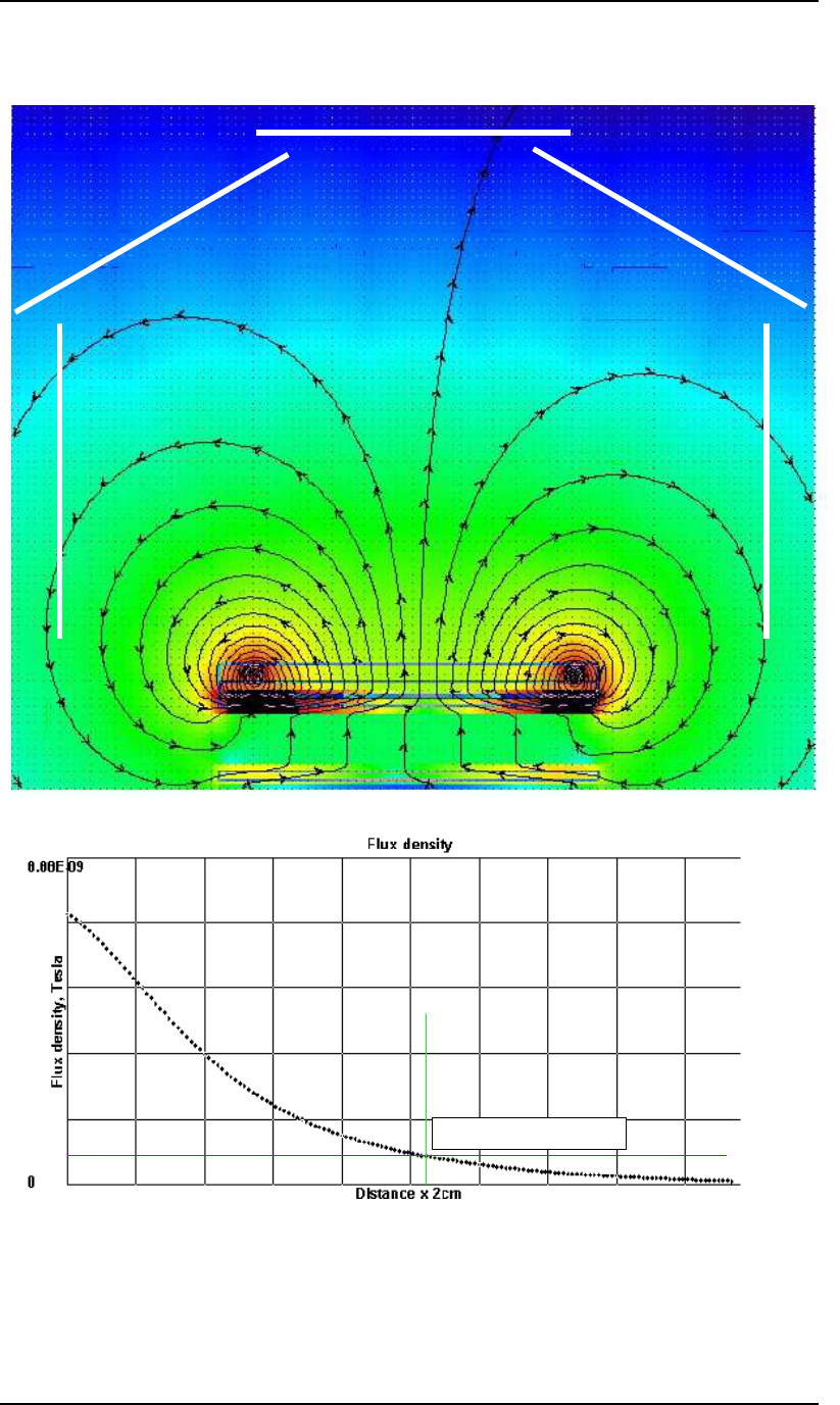
3.5 Field Strength Profile of CSC-RW
Min. Reading Field Strength
Figure 3.10 Magnetic Field Strength profile of SR14+ABC Reader

SR14+ABC CSC-RW T
ECHNICAL
M
ANUAL
V
ERSION
1.0 C
ONFIDENTIAL
12
Section 4:
Operational Precautions
4.1 General Safety Instructions
When using the SR14+ABC reader, general safety precautions should always be
followed.
1. Handle bare boards with care
2. Only operate the product with the indicated power supply requirement

SR14+ABC CSC-RW T
ECHNICAL
M
ANUAL
V
ERSION
1.0 C
ONFIDENTIAL
13
4.2 Installation
SR14+ABC reader is a contact-less smart card reader, which uses inductive coupling
to communicate with contact-less cards. Precaution must be taken to keep the reader
far enough from metal surfaces. Refers to table below for general guidelines.
Installation of reader near a metal surface may dramatically shorten the operating
distance and increase power consumption
Descriptions Clearance
Antenna positioned above metallic
surface (ferrous or non-ferrous metal
alike)
Recommended to be > 20mm away
Any edge or sides of the antenna
against any metal surface (ferrous or
non-ferrous metal alike)
Recommended to be > 20mm away
Any closed loop formed by metal in
close proximity to antenna To be avoided at all times! Especially
within 100mm facing directly parallel to
the antenna top face.
Figure 4.1 Installation Recommendations
Please notice that installation recommendations served as a general guidelines for
SR14+ABC reader installation. It does not guarantee the performance to be consistent
over every reader installed under different scenarios.
Fine-tuning or adjustment of the antenna may still be required to achieve optimal
performance.
4.3 Diagnostic Status Indicators
Conditions Descriptions
LED – All 4 LED ON Performing Power-On Self Test during
Boot-up
Any of 4 LED remains ON after Power-
ON Self Test If any of the 4 LEDs remain ON after
Built-in Self Test on Power-Up, there is
error occurred and should be send for
technical troubleshooting.

SR14+ABC CSC-RW T
ECHNICAL
M
ANUAL
V
ERSION
1.0 C
ONFIDENTIAL
14
Section 5: Compliance Statement
This product is currently pending certification for the following compliances:
1. CE
2. FCC
3. EMC: EN61000-6-4: Part 6-4 – Generic Standards – Emission standard
for industrial environment
4. EMC: EN61000-6-2: Part 6-2 – Generic Standards – Immunity standard
for industrial Environment
Regulatory Notes
An RFID system comprises an RF transmission device, and is therefore subject to
national and international regulations. Prior to the powering and operation of the
SR14+ABC reader, relevant compliance certificate should be obtained from the
associated watchdog agency. Sale, lease or operation in some countries may be
subject to prior approval by the respective government body or other international
compliance organization.
For operation of radio telecommunication equipment in the European Union or in
countries where the CE (Conformité Européene) mark is recognized, Kenetics
Innovations, hereby, declares that the SR14+ABC Reader is in compliance with the
essential requirements and other relevant provisions of the European Council’s
R&TTE directive 1999/5/EC. Note that the SR14+ABC Reader is supplied with its
own integral antenna. Users and installers are welcomed to consult the R&TTE
directive 1999/5/EC as well as the ETSI EN 302-291-1/2 harmonized standard
whether further compliance testing is required if they intend to use their own antenna
with SR14+ABC reader control board.
In addition, the length of external cables connected to interface 10 pins of
SR14+ABC reader should not exceed 3m. Cable lengths exceeding 3m may not
necessarily degrade the performance of the reader but would have to be subject to
further compliance test associated with the CE mark. Kenetics will not be liable for
cable installations that exceed 3m.
For countries requiring FCC certification, a typical system configuration
containing the SR14+ABC reader has been tested and found to be compliant with the
limits for a FCC Part 15C (intentional radiator) device. Nonetheless, it is still the
responsibility of the customers to have their complete system tested and approved for
use from the appropriate compliance agencies/authorities before operating or selling
the system. As part of FCC part 15 compliance requirements, it should be noted that:
• Modifications not expressly approved by this company could void the user’s
authority to operate the SR14+ABC reader.
• The SR14+ABC reader complies with Part 15 of the FCC Rules. Operation is
subject to the following two conditions: (1) The SR14+ABC reader may not
cause harmful interference, and (2) must accept any interference received,
including interference that may cause undesired operation.
~~ End Of Document ~~