Kenmore Elite 40188523211 User Manual MICROWAVE/HOOD COMBO Manuals And Guides 1009427L
User Manual: Kenmore Elite 40188523211 40188523211 KENMORE ELITE MICROWAVE/HOOD COMBO - Manuals and Guides View the owners manual for your KENMORE ELITE MICROWAVE/HOOD COMBO #40188523211. Home:Kitchen Appliance Parts:Kenmore Elite Parts:Kenmore Elite MICROWAVE/HOOD COMBO Manual
Open the PDF directly: View PDF ![]() .
.
Page Count: 44
E L 1 T E
B
icrowave ood Corn
Installation Instructions
ination
Combinacion icroondas Compana
_nst_ucciones de insta_aci6n
Models/Modelos 88522
88523
88529
I
I
m
L_
\
_______--------
oooo°°°°°°_'-'s°°°°°° _0
0 0 O0 0 0 IL""--_ 0 O0 0 O0
READ CAREFULLY AND SAVE THESE iNSTALLATiON iNSTRUCTiONS.
LEA ESTAS INSTRUCCIONES DE INSTALACION CON DETENllVllENTOY CONSERVELAS.
TA
CO EOF
NTS
iMPORTANT SAFETY iNSTRUCTiONS ............ 3
Electrical Requirements ...................... 3
Electrical safety instructions ................... 3
BEFOREYOU BEGIN .......................... 4
Hood Exhaust .............................. 4
Damage - Shipment/Installation ................ 6
Parts Included .............................. 6
Tools you will need .......................... 7
Mounting Space ............................ 7
iNSTALLATiONS............................. 8
Placement of the Mounting Plate ............... 8
Installation Types (choose A, B or C) ........... 11
A. Recirculating (non-vented ductless) .......... 12
B. Outside Top Exhaust (Vertical Duct) .......... 14
C. Outside Back Exhaust (Horizontal duct) ....... 18
READ THESE INSTRUCTIONS COMPLETELY AND
CAREFULLY.
•iMPORTANT - Save these instructions for local
inspector's use.
•IMPORTANT- Observe all governing codes and
ordinances.
•Note to Installer - Be sure to leave these
instructions with the Consumer.
•Note to Consumer - Keep these instructions for
future reference.
,, Skill level - Installation of this appliance requires
basic mechanical and electrical skills.
,, Proper installation is the responsibility of the
installer.
,, Product failure due to improper installation is not
covered under the Warranty.
BEFOREYOU USEYOUR MICROWAVE .......... 22
2
I
I
IPORTANT SAFETY
UCTI
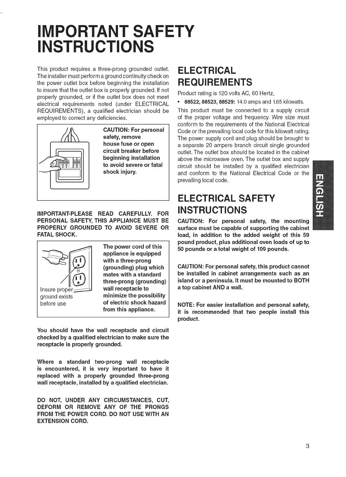
This product requires a three-prong grounded outlet.
The installer must perform a ground continuity check on
the power outlet box before beginning the installation
to insure that the outlet box is properly grounded. If not
properly grounded, or if the outlet box does not meet
electrical requirements noted (under ELECTRICAL
REQUIREMENTS), a qualified electrician should be
employed to correct any deficiencies.
CAUTION: For personal
safety, remove
house fuse or open
circuit breaker before
beginning installation
to avoid severe or fatal
shock injury,
IMPORTANT-PLEASE READ CAREFULLY. FOR
PERSONAL SAFETY, THiS APPLIANCE MUST BE
PROPERLY GROUNDED TO AVOID SEVERE OR
FATAL SHOCK.
i_[_proper _
ground exists
before use
The power cord of this
appliance is equipped
with a three-prong
(grounding) plug which
mates with a standard
three-prong (grounding)
wall receptacle to
minimize the possibility
of electric shock hazard
from this appliance.
You should have the wall receptacle and circuit
checked by a qualified electrician to make sure the
receptacle is properly grounded.
ELECTRICAL
REQUIREMENTS
Product rating is 120 volts AC, 60 Hertz,
88522, 88523, 88529:14.0 amps and 1.65 kilowatts.
This product must be connected to a supply circuit
of the proper voltage and frequency. Wire size must
conform to the requirements of the National Electrical
Code or the prevailing local code for this kilowatt rating.
The power supply cord and plug should be brought to
a separate 20 ampere branch circuit single grounded
outlet. The outlet box should be located in the cabinet
above the microwave oven. The outlet box and supply
circuit should be installed by a qualified electrician
and conform to the National Electrical Code or the
prevailing local code.
ELECTRICAL SAFETY
iNSTRUCTiONS
CAUTION: For personal safety, the mounting
surface must be capable of supporting the cabinet
load, in addition to the added weight of this 59
pound product, plus additional oven loads of up to
50 pounds or a total weight of 109 pounds.
CAUTION: For personal safety, this product cannot
be installed in cabinet arrangements such as an
island or a peninsula, it must be mounted to BOTH
a top cabinet AND a wall.
NOTE: For easier installation and personal safety,
it is recommended that two people install this
product,
Where a standard two-prong wall receptacle
is encountered, it is very important to have it
replaced with a properly grounded three-prong
wall receptacle, installed by a qualified electrician.
DO NOT, UNDER ANY CIRCUMSTANCES, CUT,
DEFORM OR REMOVE ANY OF THE PRONGS
FROM THE POWER CORD. DO NOT USE WiTH AN
EXTENSION CORD.
3
EEYOU EGI
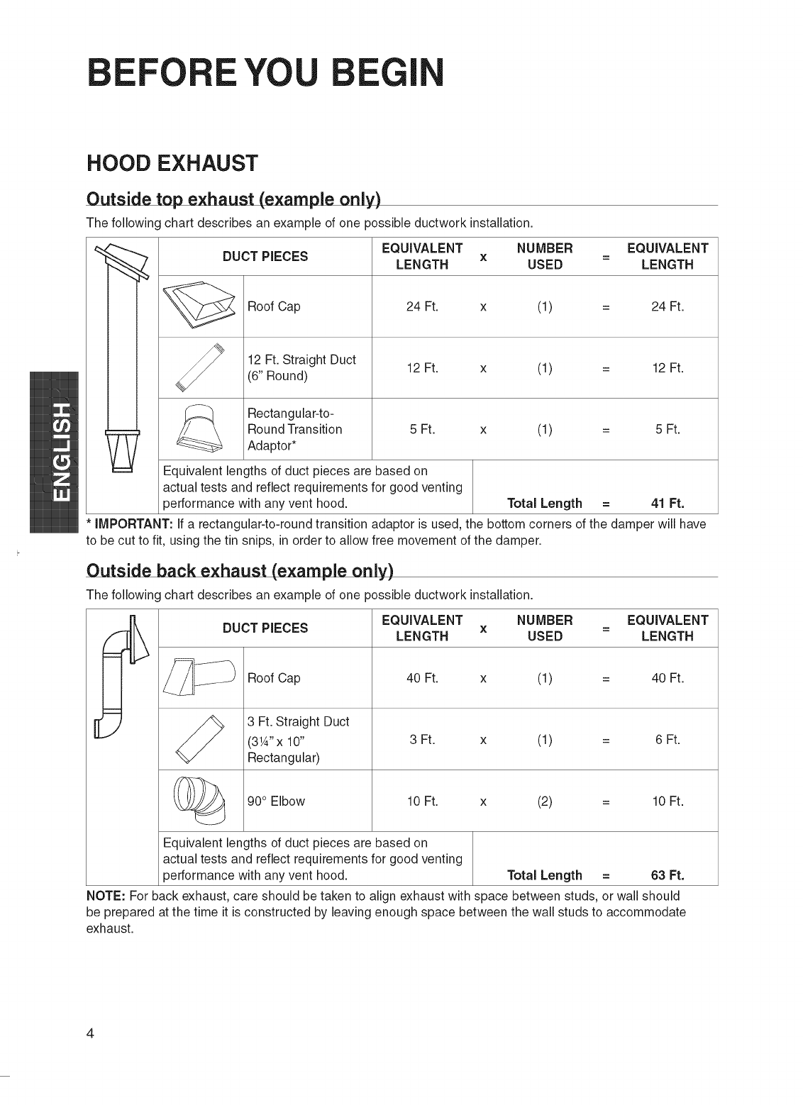
HOOD EXHAUST
Outside top exhaust (example only)
The following chart describes an example of one possible ductwork installation.
DUCT PIECES
Roof Cap 24 Ft.
12 Ft. Straight Duct 12 Ft.
(6" Round)
_ Rectangular-to-
Round Transition 5 Ft.
Adaptor*
EQUIVALENT NUMBER EQUIVALENT
X=
LENGTH USED LENGTH
x (1) = 24 Ft.
x (1) = 12 Ft.
x (1) = 5 Ft.
Equivalent lengths of duct pieces are based on
actual tests and reflect requirements for good venting
performance with any vent hood. Total Length = 41 Ft.
*iMPORTANT: if a rectangular-to-round transition adaptor is used, the bottom corners of the damper will have
to be cut to fit, using the tin snips, in order to allow free movement of the damper.
Outside back exhaust (example only)
The following chart describes an example of one possible ductwork installation.
m
Ei
DUCT PIECES
Roof Cap
3 Ft. Straight Duct
(31A"x 10"
Rectangular)
90° Elbow
EQUIVALENT NUMBER EQUIVALENT
X =
LENGTH USED LENGTH
40 Ft. x (1) = 40 Ft.
3 Ft. x (1) = 6 Ft.
10 Ft. x (2) = 10 Ft.
Equivalent lengths of duct pieces are based on
actual tests and reflect requirements for good venting
performance with any vent hood. Total Length = 63 Ft.
NOTE: For back exhaust, care should be taken to align exhaust with space between studs, or wall should
be prepared at the time it is constructed by leaving enough space between the wall studs to accommodate
exhaust.
4
iiiiiiiiiiiiiiiiiiiiiiiiiiiiiiiiiiiiiiiiiiiiiiiiiiiiiiiiiiiiiiiiiiiiiiiiiiiiiiiiiiiiiiiiiiiiiiiiiiiiiiiiiiiiiiiiiiiiiiiiiiiiiiiiiiiiiiiiiiiiiiiiiiiiiiiiiiiiiiiiiiiiiiiiiiiiiiiiiiiiiiiiiiiiiiiiiiiiiiiiiiiiiiiiiiiiiiiiiiiiiiiiiiiiiiiiiiiiiiiiiiiiiiiiiiiiiiiiiiiiiiiiiiiiiiiiiiiiiiiiiiiiiiiiiiiiiiiiiiiiiiiiiiiiiiiiiiiiiiiiiiiiiiiiiiiiiiiiiiiiiiiiiiiiiiiiiiiiiiiiiiiiiiiiiiiiiiiilliii¸;iiiii!iii!ii!i!ii!iiiiiiil_ill!fill_iiiiiiiiiii!!!iiii!iiiiiiiiii_iiiiiiiiii!iiii!ill!ill!i!iii!i!iiiili!iif!if!if!ill!iiili¸iiiii¸iiiiii!iiiiii!!!!iiiiiiliiiii!!!i!!!iiili!i!ili!_ iiiii!!!!!iliiiiillilil!iiiiiiiii!i!!iiiilliiiiiiiiiiiiiiii
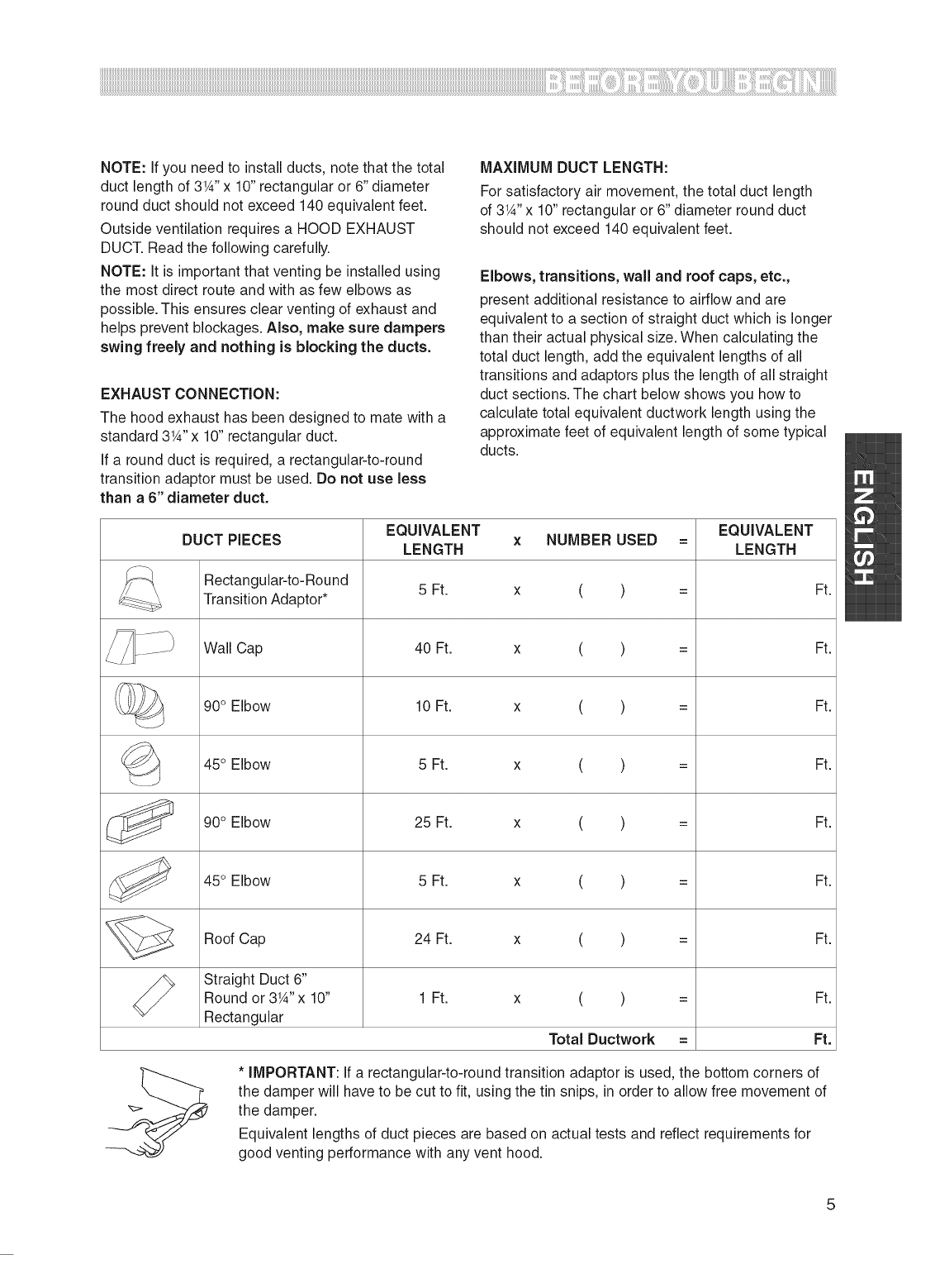
NOTE: If you need to install ducts, note that the total
duct length of 3W' x 10" rectangular or 6" diameter
round duct should not exceed 140 equivalent feet.
Outside ventilation requires a HOOD EXHAUST
DUCT. Read the following carefully.
NOTE: It is important that venting be installed using
the most direct route and with as few elbows as
possible. This ensures clear venting of exhaust and
helps prevent blockages. Also, make sure dampers
swing freely and nothing is blocking the ducts.
EXHAUST CONNECTION:
The hood exhaust has been designed to mate with a
standard 3W' x 10" rectangular duct.
If a round duct is required, a rectangular-to-round
transition adaptor must be used. Do not use less
than a 6" diameter duct.
MAXIMUM DUCT LENGTH:
For satisfactory air movement,the total duct length
of 3W' x 10" rectangular or 6" diameter round duct
should not exceed 140 equivalent feet.
Elbows, transitions, wall and roof caps, etc.,
present additional resistance to airflow and are
equivalent to a section of straight duct which is longer
than their actual physical size. When calculating the
total duct length, add the equivalent lengths of all
transitions and adaptors plus the length of all straight
duct sections. The chart below shows you how to
calculate total equivalent ductwork length using the
approximate feet of equivalent length of some typical
ducts.
EQUIVALENT EQUIVALENT
DUCT PIECES x NUMBER USED =
LENGTH LENGTH
Rectangular-to-Round
Transition Adaptor* 5 Ft. x ( ) = Ft.
Wall Cap 40 Ft. x ( ) = Ft.
90° Elbow 10 Ft. x ( ) = Ft.
_ 45° Elbow 5 Ft. Ft.
x( )
90° Elbow 25 Ft. x ( ) = Ft.
45° Elbow 5 Ft. x ( ) = Ft.
Roof Cap 24 Ft. x ( ) = Ft.
Straight Duct 6"
Round or 3W' x 10" 1 Ft. x ( ) = Ft.
Rectangular
Total Ductwork = Ft.
* iMPORTANT: If a rectangular-to-round transition adaptor is used, the bottom corners of
the damper will have to be cut to fit, using the tin snips, in order to allow free movement of
the damper.
Equivalent lengths of duct pieces are based on actual tests and reflect requirements for
good venting performance with any vent hood.
5
iiiiiiiiiiiiii i!i! i ! iiii!i!!! i ! ! ! !!!! iiiiiiiiiiiiiiiiiiiiiiiiiiiiiiiiiiiiiiiiiiiiiiiiiiiiiiiiiiiiiiiiiiiiiiiiiiiiiiiiiiiiiiiiiiiiiiiiiiiiiiiiiiiiiiiiiiiiiiiiiiiiiiiiiiiiiiiiiiiiiiiiiiiiiiiiiiiiiiiiiiiiiiiiiiiiiiiiiiiiiiiiiiiiiiiiiiiiiiiiiiiiiiiiiiiiiiiiiiiiiiiiiiiiiiiiiiiiiiiiiiiiiiiiiiiiiiiiiiiiiiiiiiiiiiiiiiiiiiiiiiiiiiiiiiiiiiiiiiiiiiiiiiiiiiiiiiiiiiiiiiiiiiiiiiiiiiiiiiiiiiiiiiiiiiiiiiiiiiiiiiiiiiiiii
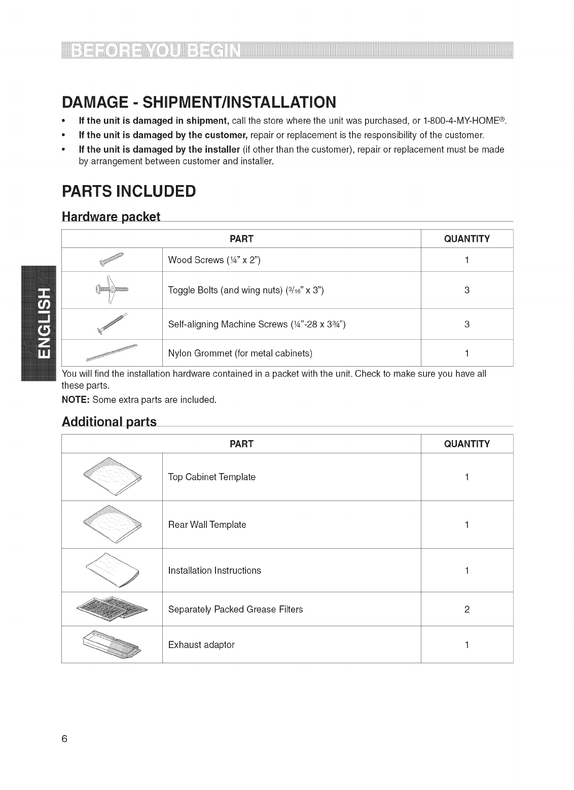
DAMAGE - SHIPMENT/INSTALLATION
• if the unit is damaged in shipment, call the store where the unit was purchased, or 1-800-4-MY-HOME ®.
• if the unit is damaged by the customer, repair or replacement is the responsibility of the customer.
• if the unit is damaged by the installer (if other than the customer), repair or replacement must be made
by arrangement between customer and installer.
PARTS iNCLUDED
Hardware packet
PART QUANTITY
Wood Screws (1A"x 2") 1
Toggle Bolts (and wing nuts) (3/16"x 3") 3
:/
Self-aligning Machine Screws (W'-28 x 33A'') 3
Nylon Grommet (for metal cabinets) 1
You will find the installation hardware contained in a packet with the unit. Check to make sure you have all
these parts.
NOTE: Some extra parts are included.
Additional parts
PART QUANTITY
Top Cabinet Template 1
Rear Wall Template 1
Installation Instructions 1
_ Separately Packed Grease Filters 2
Exhaust adaptor 1
6
iiiiiiiiiiiiiiiiiiiiiiiiiiiiiiiiiiiiiiiiiiiiiiiiiiiiiiiiiiiiiiiiiiiiiiiiiiiiiiiiiiiiiiiiiiiiiiiiiiiiiiiiiiiiiiiiiiiiiiiiiiiiiiiiiiiiiiiiiiiiiiiiiiiiiiiiiiiiiiiiiiiiiiiiiiiiiiiiiiiiiiiiiiiiiiiiiiiiiiiiiiiiiiiiiiiiiiiiiiiiiiiiiiiiiiiiiiiiiiiiiiiiiiiiiiiiiiiiiiiiiiiiiiiiiiiiiiiiiiiiiiiiiiiiiiiiiiiiiiiiiiiiiiiiiiiiiiiiiiiiiiiiiiiiiiiiiiiiiiiiiiiiiiiiiiiiiiiiiiiiiiiiiiiiiiiiiiiilliii¸;iiiii!iii!ii!i!ii!iiiiiiil_ill!fill_iiiiiiiiiii!!!iiii!iiiiiiiiii_iiiiiiiiii!iiii!ill!ill!i!iii!i!iiiili!iif!ill!ill!ill!iiili¸iiiii¸iiiiii!iiiiii!!!!iiiiiiliiiii!!!i!!!iiili!i!ili!_ iiiii!!!!!iliiiiillililCIiiiiiiiiiiiiiiii
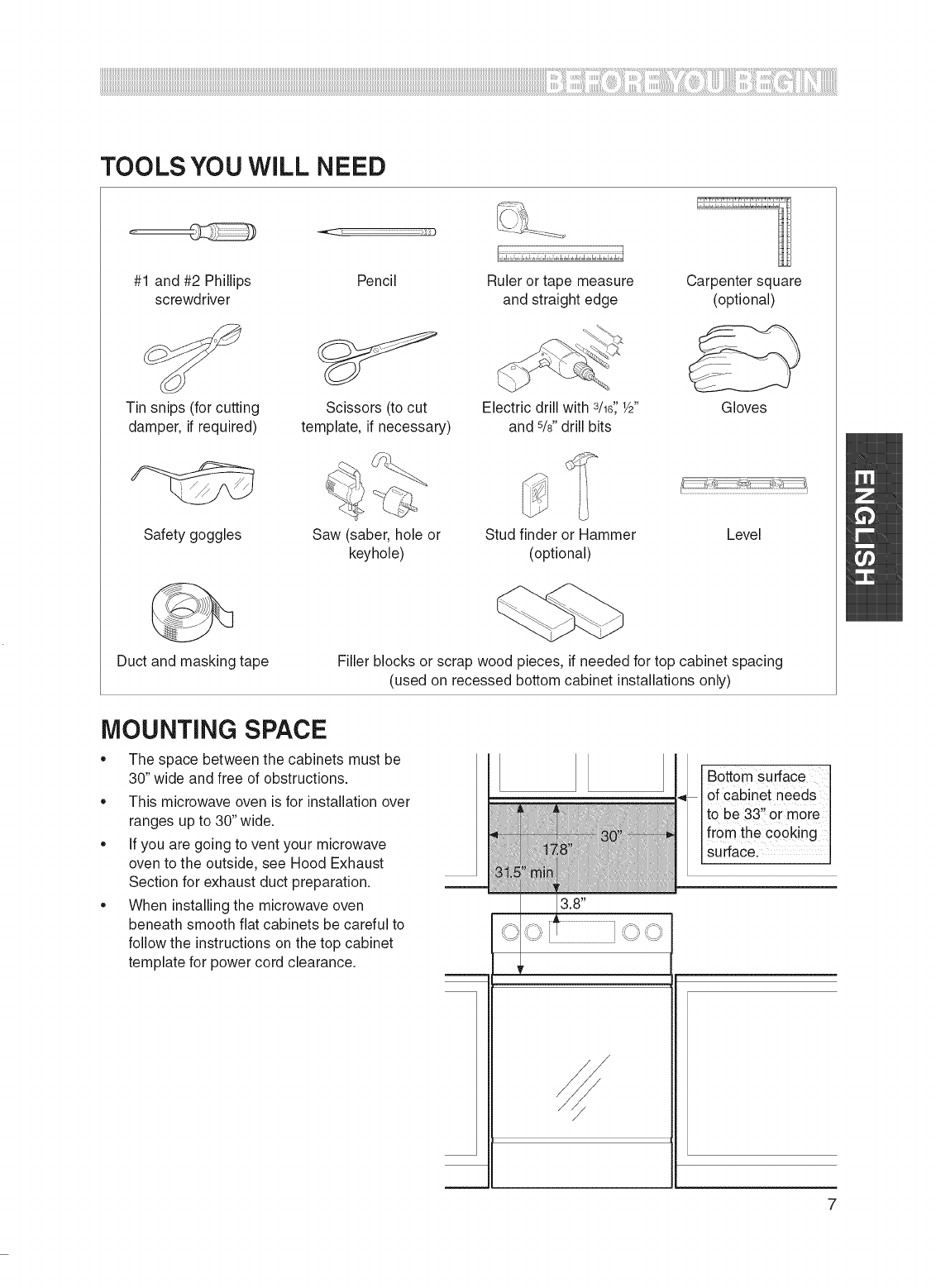
TOOLS YOU WILL NEED
#1 and #2 Phillips Pencil Ruler or tape measure Carpenter square
screwdriver and straight edge (optional)
Tin snips (for cutting
damper, if required)
Safety goggles
Scissors (to cut
template, if necessary)
Electric drill with 3/1_';W'
and 5/s"drill bits
Gloves
Stud finder or Hammer
(optional)
Saw (saber, hole or Level
keyhole)
Duct and masking tape Filler blocks or scrap wood pieces, if needed for top cabinet spacing
(used on recessed bottom cabinet installations only)
MOUNTING SPACE
,, The space between the cabinets must be
30" wide and free of obstructions.
,, This microwave oven is for installation over
ranges up to 30" wide.
,, If you are going to vent your microwave
oven to the outside, see Hood Exhaust
Section for exhaust duct preparation.
• When installing the microwave oven
beneath smooth flat cabinets be careful to
follow the instructions on the top cabinet
template for power cord clearance.
Bottom surface
__ . ,of cabinet needs
ito be 33,,or more
ifr0m the €00king
isurfaCe.
3.8"
/
7
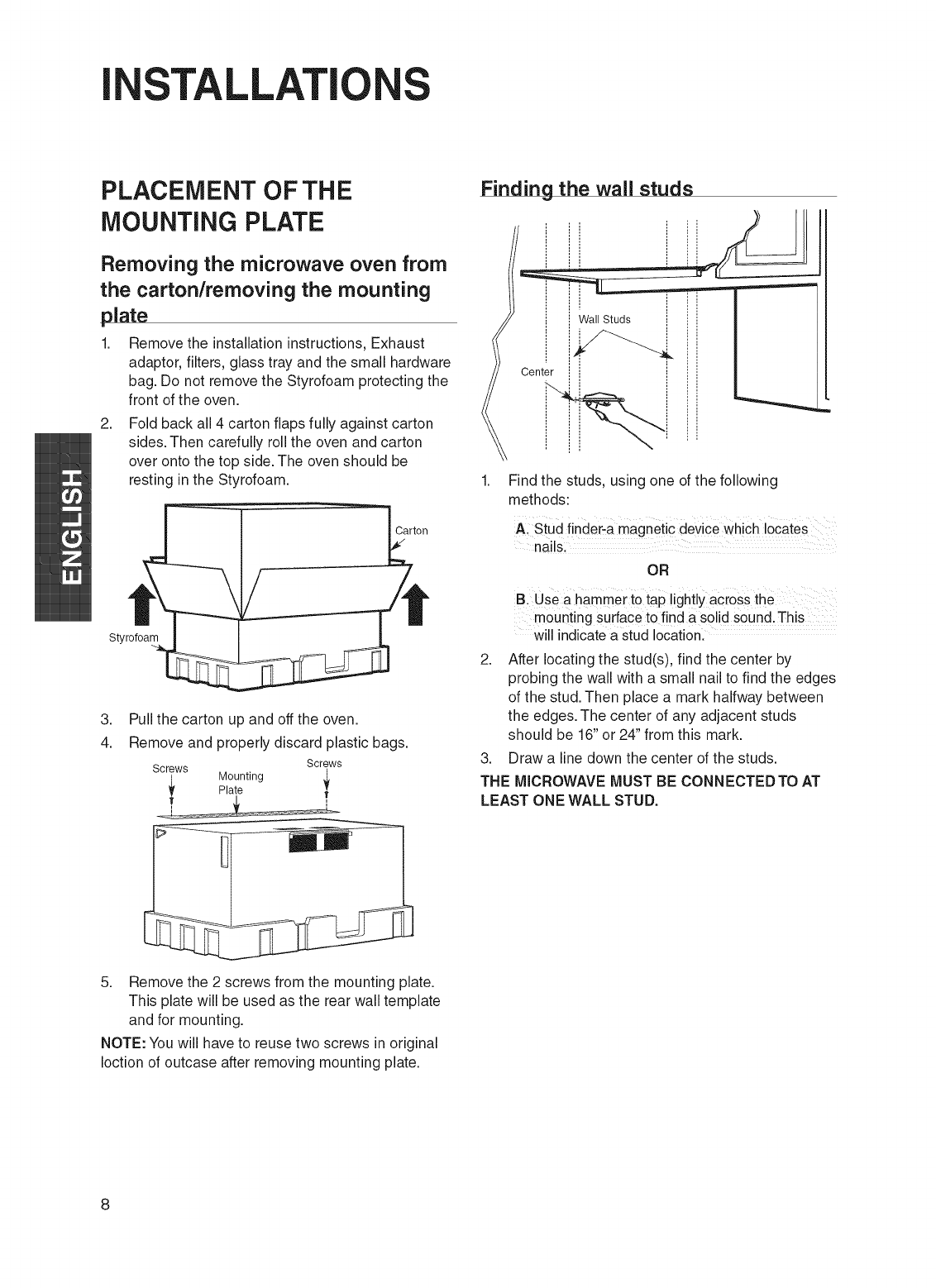
INSTALLATIO S
PLACEMENT OF THE
MOUNTING PLATE
Removing the microwave oven from
the carton/removing the mounting
plate
1. Remove the installation instructions, Exhaust
adaptor, filters, glass tray and the small hardware
bag. Do not remove the Styrofoam protecting the
front of the oven.
2. Fold back all 4 carton flaps fully against carton
sides. Then carefully roll the oven and carton
over onto the top side. The oven should be
resting in the Styrofoam.
Carton
Styrofoam
3.
4.
Pull the carton up and off the oven.
Remove and properly discard plastic bags.
Screws Screws
_, Mounting _t
Plate I
Finding the wall studs
/Center
Wall Studs
Find the studs, using one of the following
methods:
AI Stud finder-a magnetic device which locates
nails.
OR
B. Use a hamme r to tap !ightly across the
mounting surface to find a solid S0und.This
will indicate a stud location.
2. After locating the stud(s), find the center by
probing the wall with a small nail to find the edges
of the stud. Then place a mark halfway between
the edges. The center of any adjacent studs
should be 16" or 24" from this mark.
3. Draw a line down the center of the studs.
THE MICROWAVE MUST BE CONNEOTEDTO AT
LEAST ONE WALL STUD.
5. Remove the 2 screws from the mounting plate.
This plate will be used as the rear wall template
and for mounting.
NOTE: You will have to reuse two screws in original
Ioction of outcase after removing mounting plate.
8
iiiiiiiiiiiiiiiiiiiiiiiiiiiiiiiiiiiiiiiiiiiiiiiiiiiiiiiiiiiiiiiiiiiiiiiiiiiiiiiiiiiiiiiiiiiiiiiiiiiiiiiiiiiiiiiiiiiiiiiiiiiiiiiiiiiiiiiiiiiiiiiiiiiiiiiiiiiiiiiiiiiiiiiiiiiiiiiiiiiiiiiiiiiiiiiiiiiiiiiiiiiiiiiiiiiiiiiiiiiiiiiiiiiiiiiiiiiiiiiiiiiiiiiiiiiiiiiiiiiiiiiiiiiiiiiiiiiiiiiiiiiiiiiiiiiiiiiiiiiiiiiiiiiiiiiiiiiiiiiiiiiiiiiiiiiiiiiiiiiiiiiiiiiiiiiiiiiiiiiiiiiiiiiiiiiiiiiiiiiiiiiiiiiiiiiiiiiiiiiiiiiiiiiiiiiiiiiiiiiiiiiiiiiiiiiiiiiiiiiii!i_!iii!!!iiiiliiii_!ii_ii_i!_i_il¸i_!i!ii!i_iiiiiiii_!'_!'ii_ii_iiiilliii'!_!_ii!iil!i_i_i_i_i_i_i_i_i_i_i_i_iiiiiiiililiiililililii_ii!_!_!_iiiiliiii_!_!_ii_ii_i_iiiiilliiiiiiiiiiiilli!_ii_i_i_i_i_i_!_i!_!iiiii_ii_iiiiiCililililililililili
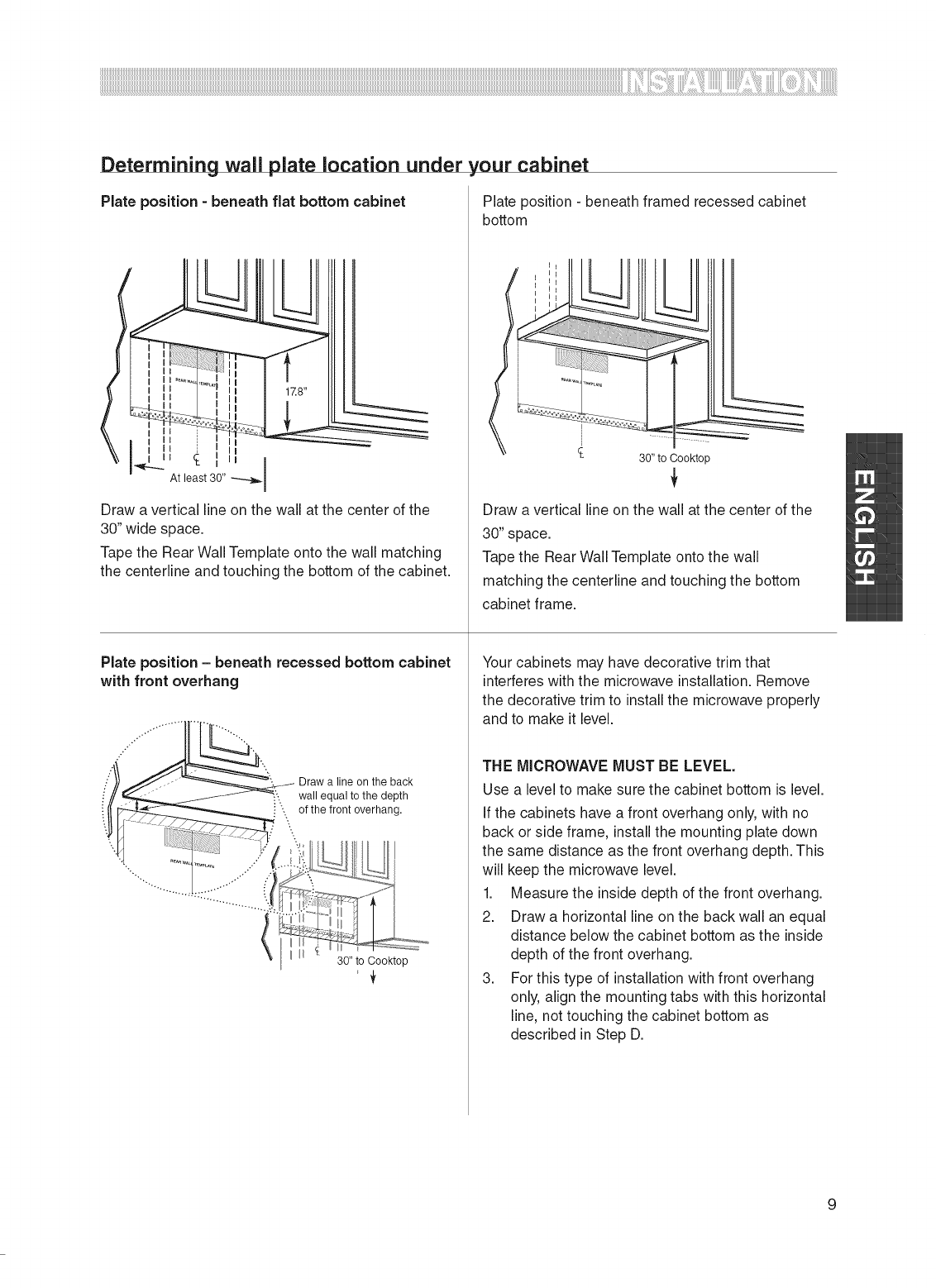
Determining wall plate location under
Plate position -beneath fiat bottom cabinet
Draw a vertical line on the wall at the center of the
30" wide space.
Tape the Rear Wall Template onto the wall matching
the centerline and touching the bottom of the cabinet.
Plate position - beneath recessed bottom cabinet
with front overhang
',our cabinet
Plate position - beneath framed recessed cabinet
bottom
Draw a line on the back
wall equal to the depth
of the front overhang.
30" to Cooktop
30" to Cooktop
Draw a vertical line on the wall at the center of the
30" space.
Tape the Rear Wall Template onto the wall
matching the centerline and touching the bottom
cabinet frame.
Your cabinets may have decorative trim that
interferes with the microwave installation. Remove
the decorative trim to install the microwave properly
and to make it level.
THE M_CROWAVE MUST BE LEVEL.
Use a level to make sure the cabinet bottom is level.
If the cabinets have a front overhang only, with no
back or side frame, install the mounting plate down
the same distance as the front overhang depth. This
will keep the microwave level.
1. Measure the inside depth of the front overhang.
2. Draw a horizontal line on the back wall an equal
distance below the cabinet bottom as the inside
depth of the front overhang.
3. For this type of installation with front overhang
only, align the mounting tabs with this horizontal
line, not touching the cabinet bottom as
described in Step D.
9
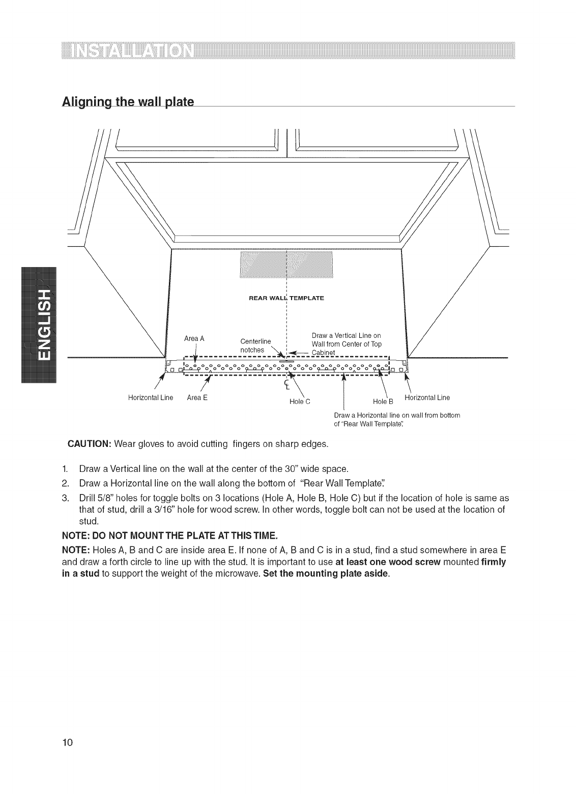
Aligning the wall plate
REAR WALL_ TEMPLATE
Draw a Vertical Line on
Area A Centerline Wall from Center of Top
......... n°t@es "_i_-- Cabinet
ooooooo
Horizontal Line Area E Horizontal Line
Hole C Hole B
Draw a Horizontal line on wall from bottom
of "Rear Wall Template'_
CAUTION: Wear gloves to avoid cutting fingers on sharp edges.
1. Draw a Vertical line on the wall at the center of the 30" wide space.
2. Draw a Horizontal line on the wall along the bottom of "Rear Wall Template'.'
3. Drill 5/8" holes for toggle bolts on 3 locations (Hole A, Hole B, Hole C) but if the location of hole is same as
that of stud, drill a 3/16" hole for wood screw. In other words, toggle bolt can not be used at the location of
stud.
NOTE: DO NOT MOUNTTHE PLATE ATTHIS TIME.
NOTE: Holes A, B and C are inside area E. if none of A, B and C is in a stud, find a stud somewhere in area E
and draw a forth circle to line up with the stud. it is important to use at least one wood screw mounted firmly
in a stud to support the weight of the microwave. Set the mounting plate aside.
10
iiiiiiiiiiiiiiiiiiiiiiiiiiiiiiiiiiiiiiiiiiiiiiiiiiiiiiiiiiiiiiiiiiiiiiiiiiiiiiiiiiiiiiiiiiiiiiiiiiiiiiiiiiiiiiiiiiiiiiiiiiiiiiiiiiiiiiiiiiiiiiiiiiiiiiiiiiiiiiiiiiiiiiiiiiiiiiiiiiiiiiiiiiiiiiiiiiiiiiiiiiiiiiiiiiiiiiiiiiiiiiiiiiiiiiiiiiiiiiiiiiiiiiiiiiiiiiiiiiiiiiiiiiiiiiiiiiiiiiiiiiiiiiiiiiiiiiiiiiiiiiiiiiiiiiiiiiiiiiiiiiiiiiiiiiiiiiiiiiiiiiiiiiiiiiiiiiiiiiiiiiiiiiiiiiiiiiiiiiiiiiiiiiiiiiiiiiiiiiiiiiiiiiiiiiiiiiiiiiiiiiiiiiiiiiiiiiiiii ] ! ! i71¸i !i!ii!77;i !' !'ii ii iiii;iill I!I I!I I!I I I ;IIII
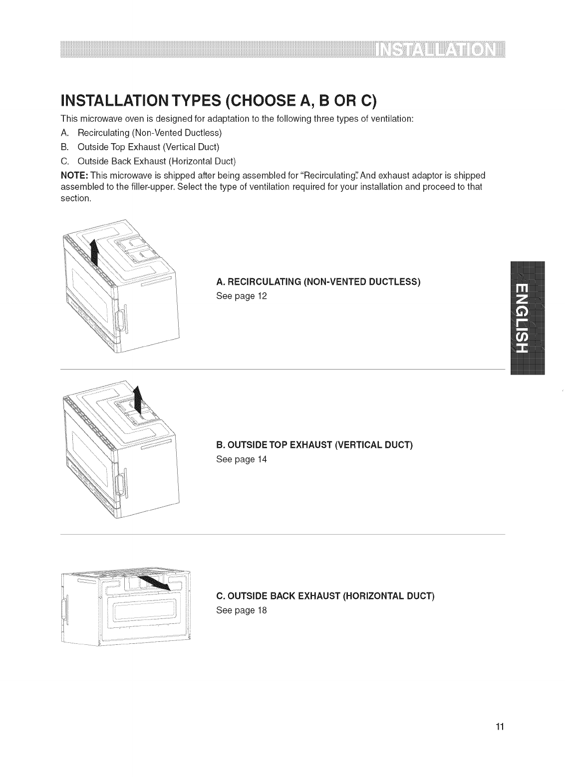
iNSTALLATiON TYPES (CHOOSE A, B OR C)
This microwave oven is designed for adaptation to the following three types of ventilation:
A. Recirculating (Non-Vented Ductless)
B. Outside Top Exhaust (Vertical Duct)
C. Outside Back Exhaust (Horizontal Duct)
NOTE: This microwave is shipped after being assembled for "RecirculatingTAnd exhaust adaptor is shipped
assembled to the filler-upper. Select the type of ventilation required for your installation and proceed to that
section.
A. RECIRCULATING (NON-VENTED DUCTLESS)
See page 12
B. OUTSIDE TOP EXHAUST (VERTICAL DUCT)
See page 14
C. OUTSIDE BACK EXHAUST (HORIZONTAL DUCT)
See page 18
11

A=
_NSTALLAT_ON OVERWEW
AI. Attach mounting plate to wall
A2. Prepare top cabinet
A3. Mount the microwave oven
RECIRCULATING (NON-VENTED DUCTLESS)
A1.Attach the mounting plate to the
wall
===_====
Attach the plate to the wall using toggle bolts. At least
one wood screw must be used to attach the plate to a
wall stud.
1. Remove the toggle wings from the bolts.
2. Insert the bolts into the mounting plate through the
holes designated to go into drywall and reattach the
toggle wings to 3_,,onto each bolt.
To use toggle bolts:
Mounting
Plate
Spacing for Toggles More Than
-_-_.,,.._11 Thickness
i Toggle Wings
H _ "_ Bolt End
3. Place the mounting plate against the wall and insert
the toggle wings into the holes in the wall to mount
the plate.
NOTE: Before tightening toggle bolts and wood
screw, make sure to line up bottom line of the
Mounting plate with Horizontal line of "Rear wall
Template" and then the Mounting plate is properly
centered under the cabinet.
CAUTION: Be careful to avoid pinching fingers
between the back of the mounting plate and the wall.
4. Tighten all bolts. Pull the plate away from the wall to
help tighten the bolts.
A2. Use top cabinet template for
preparation of top cabinet
You need to drill holes for the top support screws and
a hole large enough for the power cord to fit through.
,, Read the instructions on the TOP CABINET
TEMPLATE.
,, Tape it underneath the top cabinet.
,, Drill the holes, following the instructions on the
TOP CABINET TEMPLATE.
CAUTION: Wear safety goggles when drilling holes in
the cabinet bottom.
12
iiiiiiiiiiiiiiiiiiiiiiiiiiiiiiiiiiiiiiiiiiiiiiiiiiiiiiiiiiiiiiiiiiiiiiiiiiiiiiiiiiiiiiiiiiiiiiiiiiiiiiiiiiiiiiiiiiiiiiiiiiiiiiiiiiiiiiiiiiiiiiiiiiiiiiiiiiiiiiiiiiiiiiiiiiiiiiiiiiiiiiiiiiiiiiiiiiiiiiiiiiiiiiiiiiiiiiiiiiiiiiiiiiiiiiiiiiiiiiiiiiiiiiiiiiiiiiiiiiiiiiiiiiiiiiiiiiiiiiiiiiiiiiiiiiiiiiiiiiiiiiiiiiiiiiiiiiiiiiiiiiiiiiiiiiiiiiiiiiiiiiiiiiiiiiiiiiiiiiiiiiiiiiiiiiiiiiiiiiiiiiiiiiiiiiiiiiiiiiiiiiiiiiiiiiiiiiiiiiiiiiiiiiiiiiiiiiiiiiiii!i_!iii!!!iiiiliiii_!ii_ii_i!_:i_il¸i_!i!ii!i_iiiiii:i_!'_!'ii_ii_iiiilliii'!_!_ii!iil!i_i_i_i_i_i_i_i_i_i_i_i_iiiiiiiililiiililililii_ii!_!_!_iiiiliiii_!_!_ii_ii_i_iiiiilliiiiiiiiiiiilli!_ii_i_i_i_i_i_!_i!_!i:iii_ii_iiiiiCililililililililili
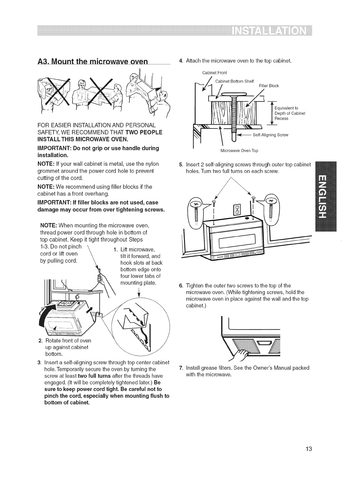
A3. Mount the microwave oven
FOR EASIER INSTALLATIONAND PERSONAL
SAFETY,WE RECOMMEND THAT TWO PEOPLE
INSTALL THIS MICROWAVEOVEN.
iMPORTANT:Do not grip or use handle during
installation,
NOTE: If your wall cabinet is metal, use the nylon
grommet aroundthe power cord hole to prevent
cutting of the cord.
NOTE: We recommend using filler blocks if the
cabinet has a front overhang.
IMPORTANT: ff filler blocks are not used, case
damage may occur from over tightening screws.
1-3.Do not pinch
cord or lift oven
by pulling cord.
NOTE: When mounting the microwave oven,
thread power cord through hole in bottom of
top cabinet. Keep it tight throughout Steps
1. Lift microwave,
tilt it forward, and
hook slots at back
bottom edge onto
four lower tabs of
mounting plate.
2. Rotate front of oven
up against cabinet
bottom.
3. Insert a self-aligning screw through top center cabinet
hole. Temporarily secure the oven by turning the
screw at least two full turns after the threads have
engaged. (It will be completely tightened later.) Be
sure to keep power cord tight. Be careful not to
pinch the cord, especially when mounting flush to
bottom of cabinet.
4. Attach the microwave oven to the top cabinet.
Cabinet Front
Cabinet Bottom Shelf
Filler Block
-_quivalent to
epth of Cabinet
ecess
igning Screw
Microwave Oven Top
5. Insert 2 self-aligning screws through outer top cabinet
holes. Turn two full turns on each screw.
6. Tighten the outer two screws to the top of the
microwave oven. (While tightening screws, hold the
microwave oven in place against the wall and the top
cabinet.)
\
7. Install grease filters. See the Owner's Manual packed
with the microwave.
13
B. OUTSIDE TOP EXHAUST (VERTICAL DUCT)
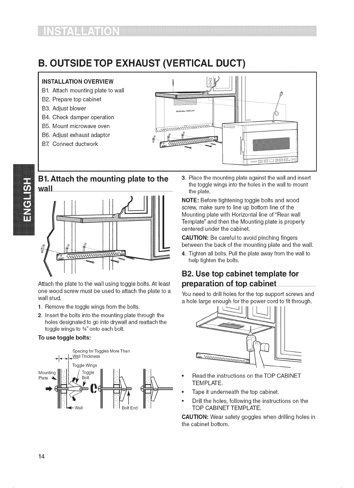
iNSTALLATiON OVERVIEW
BI. Attach mounting plate to wall
B2. Prepare top cabinet
B3. Adjust blower
B4. Check damper operation
B5. Mount microwave oven
B6. Adjust exhaust adaptor
B7. Connect ductwork
B1.Attach the mounting plate to the
wall
====_==,
Attach the plate to the wall using toggle bolts. At least
one wood screw must be used to attach the plate to a
wall stud.
1. Remove the toggle wings from the bolts.
2. Insert the bolts into the mounting plate through the
holes designated to go into drywall and reattach the
toggle wings to 3_,,onto each bolt.
To use toggle bolts:
Mounting
Plate
Spacing for Toggles More Than
-_-_.,,.._11 Thickness
i Toggle Wings
H _ "_ Bolt End
3. Place the mounting plate against the wall and insert
the toggle wings into the holes in the wall to mount
the plate.
NOTE: Before tightening toggle bolts and wood
screw, make sure to line up bottom line of the
Mounting plate with Horizontal line of "Rear wall
Template" and then the Mounting plate is properly
centered under the cabinet.
CAUTION: Be careful to avoid pinching fingers
between the back of the mounting plate and the wall.
4. Tighten all bolts. Pull the plate away from the wall to
help tighten the bolts.
B2. Use top cabinet template for
preparation of top cabinet
You need to drill holes for the top support screws and
a hole large enough for the power cord to fit through.
,, Read the instructions on the TOP CABINET
TEMPLATE.
,, Tape it underneath the top cabinet.
,, Drill the holes, following the instructions on the
TOP CABINET TEMPLATE.
CAUTION: Wear safety goggles when drilling holes in
the cabinet bottom.
14
iiiiiiiiiiiiiiiiiiiiiiiiiiiiiiiiiiiiiiiiiiiiiiiiiiiiiiiiiiiiiiiiiiiiiiiiiiiiiiiiiiiiiiiiiiiiiiiiiiiiiiiiiiiiiiiiiiiiiiiiiiiiiiiiiiiiiiiiiiiiiiiiiiiiiiiiiiiiiiiiiiiiiiiiiiiiiiiiiiiiiiiiiiiiiiiiiiiiiiiiiiiiiiiiiiiiiiiiiiiiiiiiiiiiiiiiiiiiiiiiiiiiiiiiiiiiiiiiiiiiiiiiiiiiiiiiiiiiiiiiiiiiiiiiiiiiiiiiiiiiiiiiiiiiiiiiiiiiiiiiiiiiiiiiiiiiiiiiiiiiiiiiiiiiiiiiiiiiiiiiiiiiiiiiiiiiiiiiiiiiiiiiiiiiiiiiiiiiiiiiiiiiiiiiiiiiiiiiiiiiiiiiiiiiiiiiiiiiiiiii!i_!iii!!!iiiiliiii_!ii_ii_i!_i_il¸i_!i!ii!i_iiiiiiii_!'_!'ii_ii_iiiilliii'!_!_ii!iil!i_i_i_i_i_i_i_i_i_i_i_i_iiiiiiiililiiililililii_ii!_!_!_iiiiliiii_!_!_ii_ii_i_iiiiilliiiiiiiiiiiilli!_ii_i_i_i_i_i_!_i!_!iiiii_ii_iiiiiCililililililililili
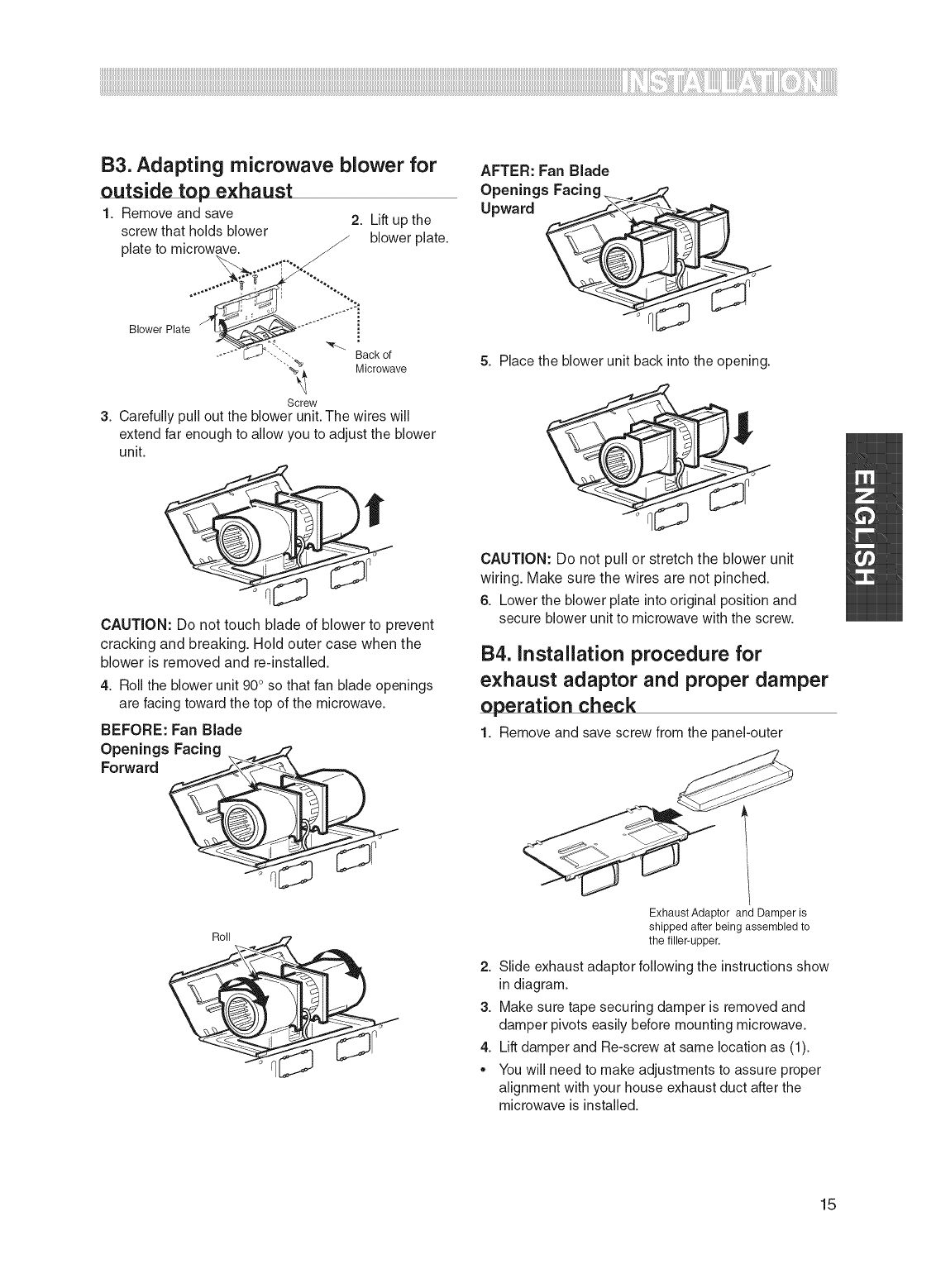
B3. Adapting microwave blower for
outside top exhaust
1. Remove and save 2. Lift up the
screw that holds blower /blower plate.
plate to microwave. J
/-
Blower Plate
Back of
"'""_ Microwave
Screw
3. Carefully pull out the blower unit. The wires will
extend far enough to allow you to adjust the blower
unit.
CAUTION: Do not touch blade of blower to prevent
cracking and breaking. Hold outer case when the
blower is removed and re-installed.
4. Roll the blower unit 90° so that fan blade openings
are facing toward the top of the microwave.
BEFORE: Fan Blade
Roll -, _
AFTER: Fan Blade
Openings Facing _,z7
Upward _
5. Place the blower unit back into the opening.
CAUTION: Do not pull or stretch the blower unit
wiring. Make sure the wires are not pinched.
6. Lower the blower plate into original position and
secure blower unit to microwave with the screw.
B4. installation procedure for
exhaust adaptor and proper damper
operation check
1. Remove and save screw from the panel-outer
Exhaust Adaptor and Damper is
shipped after being assembled to
the filler-upper.
2. Slide exhaust adaptor following the instructionsshow
indiagram.
3. Make sure tape securing damper is removed and
damper pivots easily before mounting microwave.
4. Lift damper and Re-screw at same location as (1).
You will need to make adjustments to assure proper
alignment with your house exhaust duct after the
microwave is installed.
15
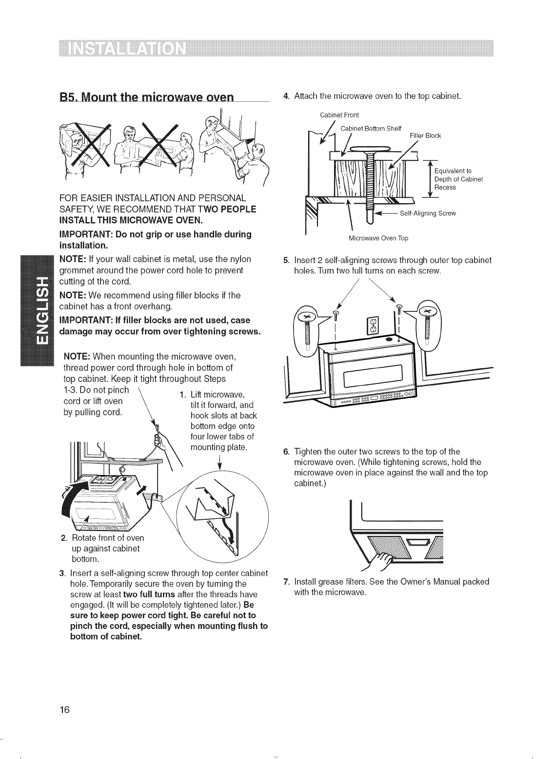
B5. Mount the microwave oven
FOR EASIER INSTALLATIONAND PERSONAL
SAFETY,WE RECOMMEND THATTWO PEOPLE
INSTALL THIS M_CROWAVEOVEN.
iMPORTANT:Do not grip or use handle during
installation.
NOTE: If your wall cabinet is metal, use the nylon
grommet aroundthe power cord hole to prevent
cutting of the cord.
NOTE: We recommend using filler blocks if the
cabinet has a front overhang.
_MPORTANT:ff filler blocks are not used, case
damage may occur from over tightening screws.
1-3.Do not pinch
cord or lift oven
by pulling cord.
NOTE: When mounting the microwave oven,
thread power cord through hole in bottom of
top cabinet. Keep it tight throughout Steps
1. Lift microwave,
tilt it forward, and
hook slots at back
bottom edge onto
four lower tabs of
mounting plate.
2. Rotate front of oven
up against cabinet
bottom.
3. Insert a self-aligning screw through top center cabinet
hole. Temporarily secure the oven by turning the
screw at least two full turns after the threads have
engaged. (It will be completely tightened later.) Be
sure to keep power cord tight. Be careful not to
pinch the cord, especially when mounting flush to
bottom of cabinet.
4. Attach the microwave oven to the top cabinet.
Cabinet Front
Cabinet Bottom Shelf
Filler Block
quivalent to
epth of Cabinet
ecess
igning Screw
Microwave Oven Top
5. Insert 2 self-aligning screws through outer top cabinet
holes. Turn two full turns on each screw.
/)
6. Tighten the outer two screws to the top of the
microwave oven. (While tightening screws, hold the
microwave oven in place against the wall and the top
cabinet.)
\
7. Install grease filters. See the Owner's Manual packed
with the microwave.
16
iiiiiiiiiiiiiiiiiiiiiiiiiiiiiiiiiiiiiiiiiiiiiiiiiiiiiiiiiiiiiiiiiiiiiiiiiiiiiiiiiiiiiiiiiiiiiiiiiiiiiiiiiiiiiiiiiiiiiiiiiiiiiiiiiiiiiiiiiiiiiiiiiiiiiiiiiiiiiiiiiiiiiiiiiiiiiiiiiiiiiiiiiiiiiiiiiiiiiiiiiiiiiiiiiiiiiiiiiiiiiiiiiiiiiiiiiiiiiiiiiiiiiiiiiiiiiiiiiiiiiiiiiiiiiiiiiiiiiiiiiiiiiiiiiiiiiiiiiiiiiiiiiiiiiiiiiiiiiiiiiiiiiiiiiiiiiiiiiiiiiiiiiiiiiiiiiiiiiiiiiiiiiiiiiiiiiiiiiiiiiiiiiiiiiiiiiiiiiiiiiiiiiiiiiiiiiiiiiiiiiiiiiiiiiiiiiiiiiiiii!i_!iii!!!iiiiliiii_!ii_ii_i!_i_il¸i_!i!ii!i_iiiiiiii_!'_!'ii_ii_iiiillii_i'!_!_ii!iil!i_i_i_i_i_i_i_i_i_i_i_i_iiiiiiiililiiililililii_ii,!_!_!'_iiiiliiii_!_!_ii_ii_i_iiiiilliiiiiiiiiiiilli!_ii_i_i_i_i_i_!_i!_!iiiii_ii_iiiiiiiiiiiii_ii_!i'_!_iiiililililililililili
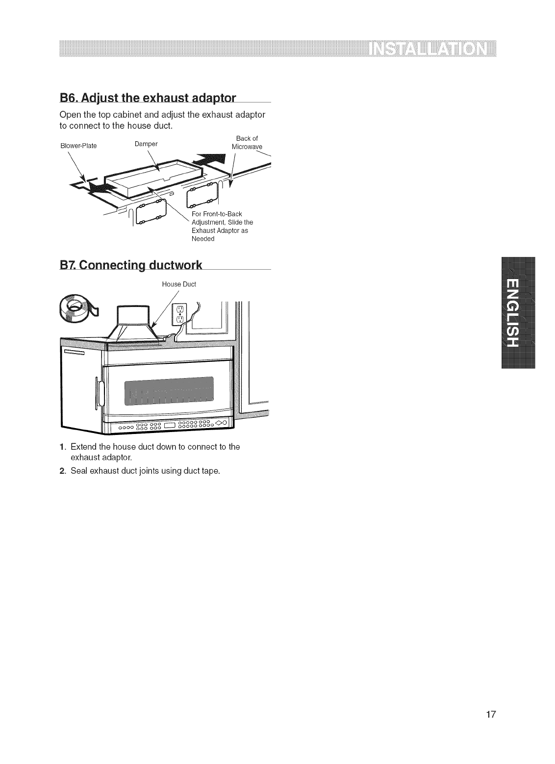
B6. Adjust the exhaust adaptor
Open the top cabinet and adjust the exhaust adaptor
to connect to the house duct.
Back of
Blower-Plate Damper Microwave
For Front-_-Back
Adjustment, Slidethe
ExhaustAdap_ras
Needed
B7. Connecting ductwork
House Duct
1. Extend the house duct down to connect to the
exhaust adaptor.
2. Seal exhaust duct joints using duct tape.
17
C. OUTSIDE BACK EXHAUST (HORIZONTAL DUCT)
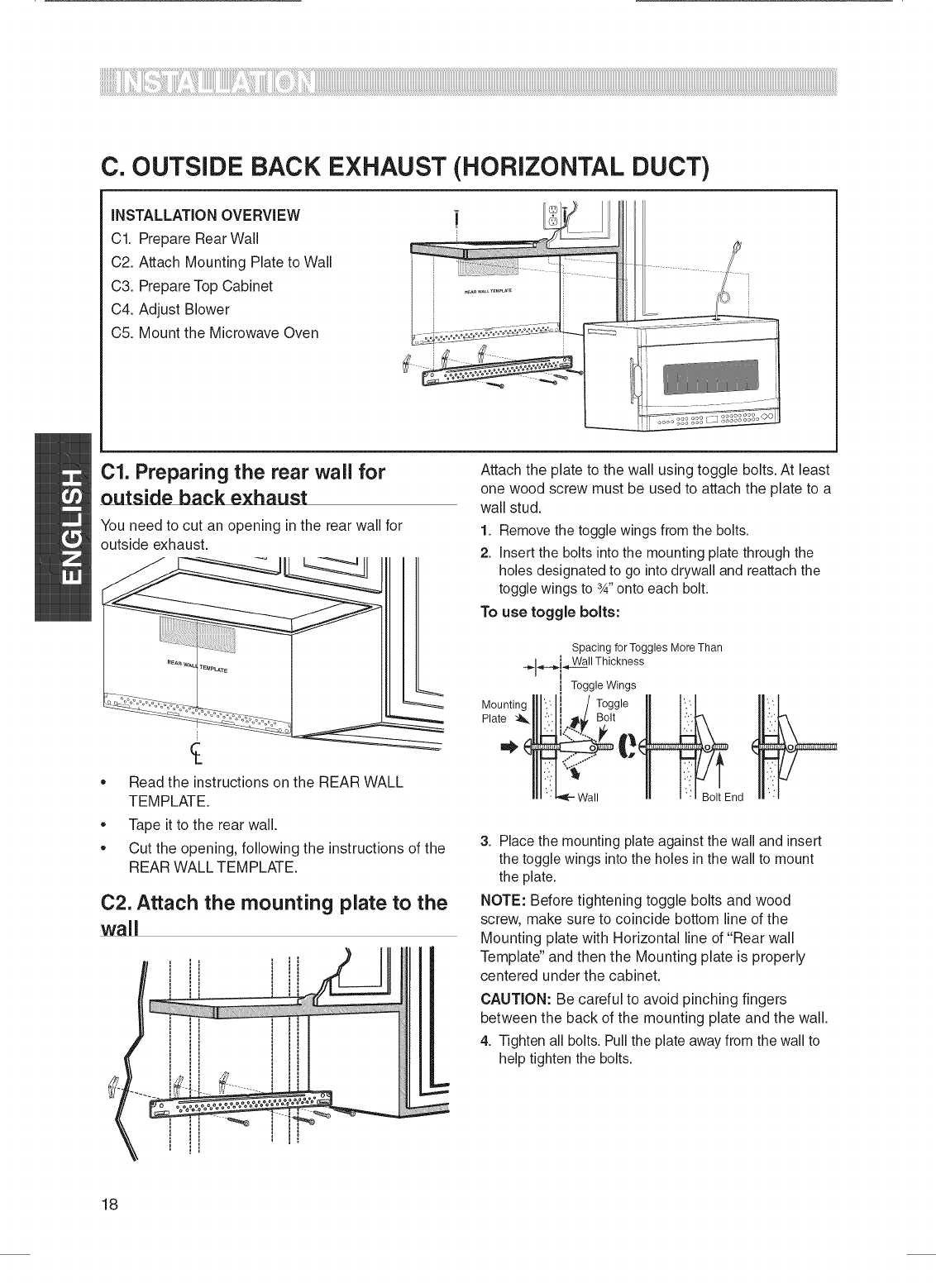
iNSTALLATiON OVERVIEW
C1. Prepare Rear Wall
C2. Attach Mounting Plate to Wall
C3. Prepare Top Cabinet
C4. Adjust Blower
C5. Mount the Microwave Oven
|
01. Preparing the rear wail for
outside back exhaust
You need to cut an opening in the rear wall for
outside exhaust.
,, Read the instructions on the REAR WALL
TEMPLATE.
,, Tape it to the rear wall.
,, Cut the opening, following the instructions of the
REAR WALL TEMPLATE.
02. Attach the mounting plate to the
wall
Attach the plate to the wall using toggle bolts. At least
one wood screw must be used to attach the plate to a
wall stud.
1. Remove the toggle wings from the bolts.
2. Insert the bolts into the mounting plate through the
holes designated to go into drywall and reattach the
toggle wings to 3_,,onto each bolt.
To use toggle bolts:
Spacing for Toggles More Than
___4_..._.i_WaWallThickness
i Toggle Wings
Mountinglll.Ii /Togg,eII l/
Plate :'_.111":'.11_¢ Bolt II t:.':_'_
Il_ '_'_[--Wall II _ '_ BoltEnd
3. Place the mounting plate against the wall and insert
the toggle wings into the holes in the wall to mount
the plate.
NOTE: Before tightening toggle bolts and wood
screw, make sure to coincide bottom line of the
Mounting plate with Horizontal line of "Rear wall
Template" and then the Mounting plate is properly
centered under the cabinet.
CAUTION: Be careful to avoid pinching fingers
between the back of the mounting plate and the wall.
4. Tighten all bolts. Pull the plate away from the wall to
help tighten the bolts.
18
iiiiiiiiiiiiiiiiiiiiiiiiiiiiiiiiiiiiiiiiiiiiiiiiiiiiiiiiiiiiiiiiiiiiiiiiiiiiiiiiiiiiiiiiiiiiiiiiiiiiiiiiiiiiiiiiiiiiiiiiiiiiiiiiiiiiiiiiiiiiiiiiiiiiiiiiiiiiiiiiiiiiiiiiiiiiiiiiiiiiiiiiiiiiiiiiiiiiiiiiiiiiiiiiiiiiiiiiiiiiiiiiiiiiiiiiiiiiiiiiiiiiiiiiiiiiiiiiiiiiiiiiiiiiiiiiiiiiiiiiiiiiiiiiiiiiiiiiiiiiiiiiiiiiiiiiiiiiiiiiiiiiiiiiiiiiiiiiiiiiiiiiiiiiiiiiiiiiiiiiiiiiiiiiiiiiiiiiiiiiiiiiiiiiiiiiiiiiiiiiiiiiiiiiiiiiiiiiiiiiiiiiiiiiiiiiiiiiiii:iL::_!i:i!!!iiiiliiii_!ii_ii_i!_:i_il¸i_!i!ii!i_iiiiii:i_!'_!':i:ii+_iiii:iii:i"!_!_ii!iil!i+i+i+i+i+i+i+i+i+i+:+:+:iiiiiiililiiililililii_ii,!+!+!'_iiiilii:i+_!_!_ii_ii_i_iii:iii:i:iiiiii::i!_ii_i_i+_i+_i_i+_!_i!_!::i:i::i:iiiiiCilililililililililL
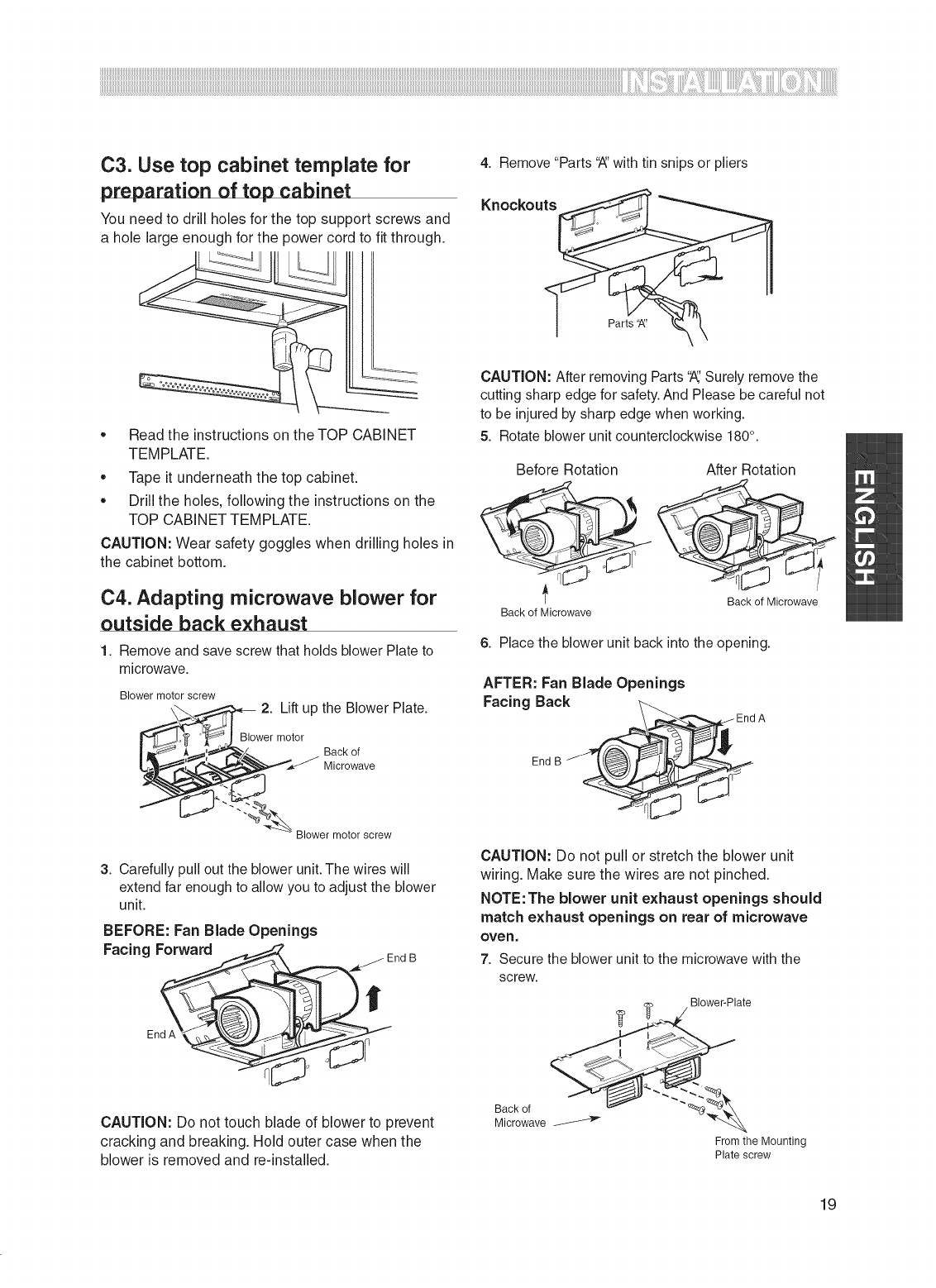
C3. Use top cabinet template for
preparation of top cabinet
You need to drill holes for the top support screws and
a hole large enough for the power cord to fit through.
4. Remove "Parts 'A' with tin snips or pliers
Knockouts
Parts 'A'
+Read the instructions on the TOP CABINET
TEMPLATE.
,, Tape it underneath the top cabinet.
,, Drill the holes, following the instructions on the
TOP CABINET TEMPLATE.
CAUTION: Wear safety goggles when drilling holes in
the cabinet bottom.
C4. Adapting microwave blower for
outside back exhaust
1. Remove and save screw that holds blower Plate to
microwave.
Blower motor screw
2. Lift up the Blower Plate.
wer mo|_ A _,=,,_'_/_ tor Back of
_ Microwave
_ Blower motor screw
3, Carefully pull out the blower unit. The wires will
extend far enough to allow you to adjust the blower
unit.
BEFORE: Fan Blade Openings
Forward End B
Facing __
End A
CAUTION: Do not touch blade of blower to prevent
cracking and breaking. Hold outer case when the
blower is removed and re-installed.
CAUTION: After removing Parts 'A,'Surely remove the
cutting sharp edge for safety. And Please be careful not
to be injuredby sharp edge when working.
5. Rotate blower unit counterclockwise 180°.
Before Rotation After Rotation
'_ Back of Microwave
Back of Microwave
6. Place the blower unit back into the opening.
AFTER: Fan Blade Openings
Facing Back
End B _En_ d
A
CAUTION: Do not pull or stretch the blower unit
wiring. Make sure the wires are not pinched.
NOTE: The blower unit exhaust openings should
match exhaust openings on rear of microwave
ove no
7. Secure the blower unit to the microwave with the
screw.
Back of
Microwave
ate
From the Mounting
Plate screw
19
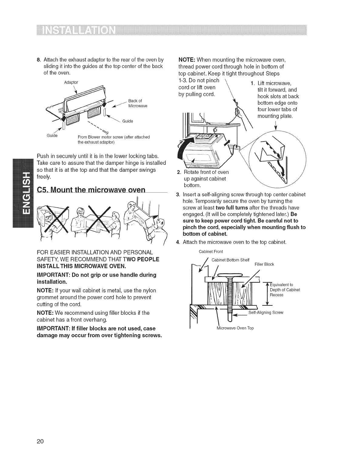
8. Attach the exhaust adaptor to the rear of the oven by
sliding it into the guides at the top center of the back
of the oven.
Adaptor
,i," j Back of
_,_ Microwave
Guide From Blower motor screw (after attached
the exhaust adaptor)
Push in securely until it is in the lower locking tabs.
Take care to assure that the damper hinge is installed
so that it is at the top and that the damper swings
freely.
C5. Mount the microwave oven
FOR EASIER INSTALLATIONAND PERSONAL
SAFETY,WE RECOMMEND THATTWO PEOPLE
INSTALL THIS M_CROWAVEOVEN.
iMPORTANT:Do not grip or use handle during
installation.
NOTE: If your wall cabinet is metal, use the nylon
grommet around the power cord hole to prevent
cutting of the cord.
NOTE: We recommend using filler blocks if the
cabinet has a front overhang.
_MPORTANT: ff filler blocks are not used, case
damage may occur from over tightening screws.
1-3.Do not pinch
cord or lift oven
by pulling cord.
NOTE: When mounting the microwave oven,
thread power cord through hole in bottom of
top cabinet. Keep it tight throughout Steps
1. Lift microwave,
tilt itforward, and
hook slots at back
bottom edge onto
four lower tabs of
mounting plate.
Rotate front of oven
up against cabinet
bottom.
3. Insert a self-aligning screw through top center cabinet
hole.Temporarily secure the oven by turning the
i screw at least two full turns after the threads have
engaged. (it will be completely tightened later.) Be
sure to keep power cord tight. Be careful not to
pinch the cord, especially when mounting flush to
bottom of cabinet.
4. Attach the microwave oven to the top cabinet.
Cabinet Front
Cabinet Bottom Shelf Filler Block
"_quivalent to
epth of Cabinet
ecess
Self-Aligning Screw
Microwave Oven Top
2O
iiiiiiiiiiiiiiiiiiiiiiiiiiiiiiiiiiiiiiiiiiiiiiiiiiiiiiiiiiiiiiiiiiiiiiiiiiiiiiiiiiiiiiiiiiiiiiiiiiiiiiiiiiiiiiiiiiiiiiiiiiiiiiiiiiiiiiiiiiiiiiiiiiiiiiiiiiiiiiiiiiiiiiiiiiiiiiiiiiiiiiiiiiiiiiiiiiiiiiiiiiiiiiiiiiiiiiiiiiiiiiiiiiiiiiiiiiiiiiiiiiiiiiiiiiiiiiiiiiiiiiiiiiiiiiiiiiiiiiiiiiiiiiiiiiiiiiiiiiiiiiiiiiiiiiiiiiiiiiiiiiiiiiiiiiiiiiiiiiiiiiiiiiiiiiiiiiiiiiiiiiiiiiiiiiiiiiiiiiiiiiiiiiiiiiiiiiiiiiiiiiiiiiiiiiiiiiiiiiiiiiiiiiiiiiiiiiiiiiiii!i_!iii!!!iiiiliiii_!ii_ii_i!_i_il¸i_!i!ii!i_iiiiiiii_!'_!'ii_ii_iiiilliii'!_!_ii!iil!i_i_i_i_i_i_i_i_i_i_i_i_iiiiiiiililiiililililii_ii!_!_!_iiiiliiii_!_!_ii_ii_i_iiiiilliiiiiiiiiiiilli!_ii_i_i_i_i_i_!_i!_!iiiii_ii_iiiiiiiiiiiiiii!i'_!_iiiililililililililili
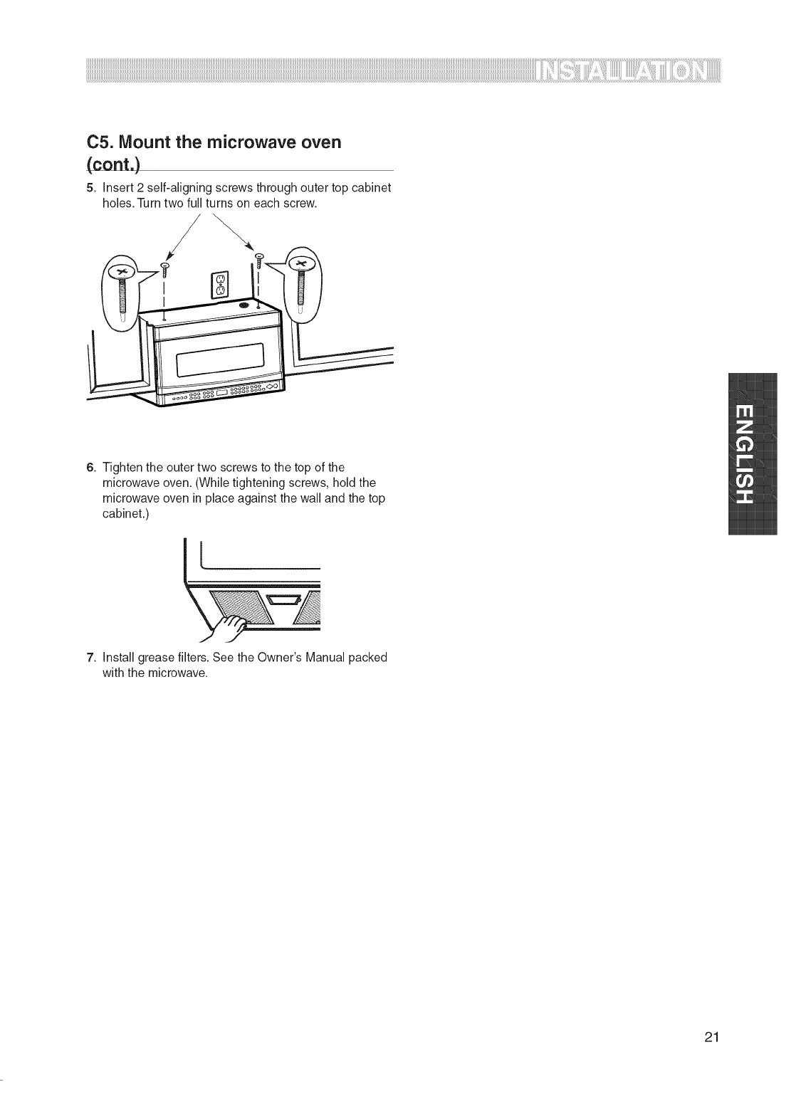
C5. Mount the microwave oven
(cont.)
5. insert 2 self-aligning screws through outer top cabinet
holes. Turn two full turns on each screw.
J
6. Tighten the outer two screws to the top of the
microwave oven. (While tightening screws, hold the
microwave oven in place against the wall and the top
cabinet.)
7. Install grease filters. See the Owner's Manual packed
with the microwave.
21
EYOU
OWAVE USEYO
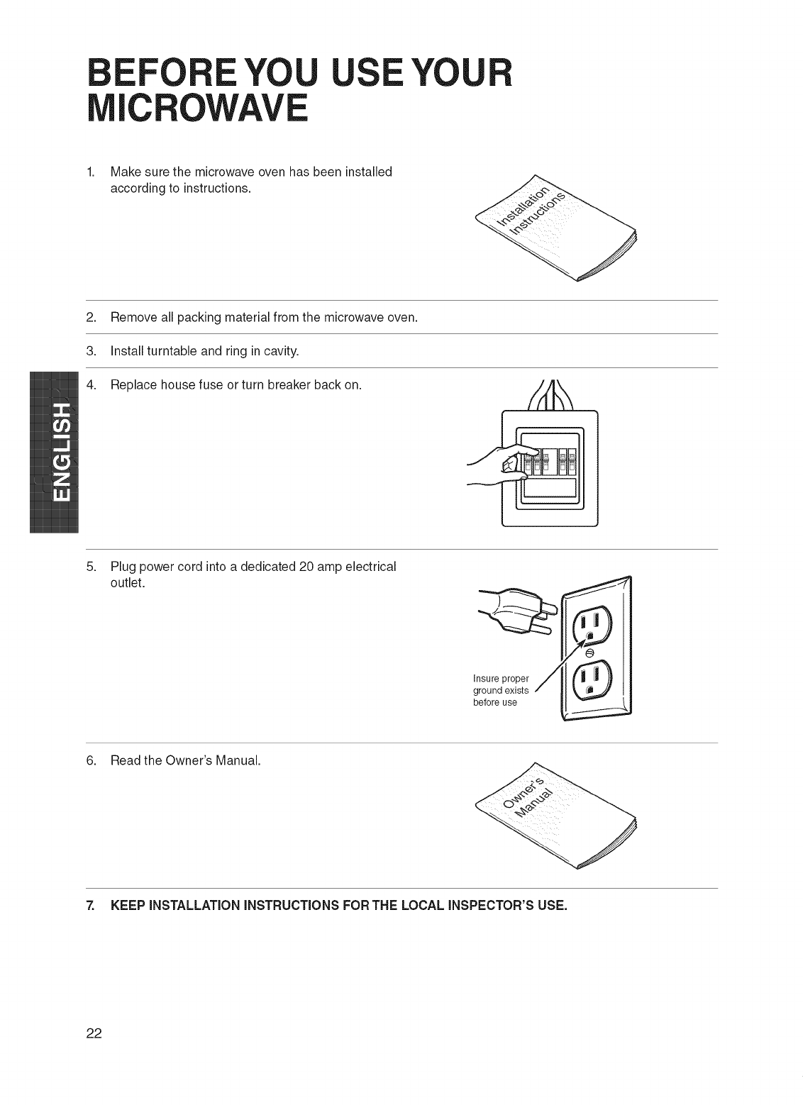
Make sure the microwave oven has been installed
according to instructions.
2. Remove all packing material from the microwave oven.
3. Install turntable and ring in cavity.
4. Replace house fuse or turn breaker back on.
5. Plug power cord into a dedicated 20 amp electrical
outlet.
Insure proper
ground exists
before use
6. Read the Owner's Manual.
7. KEEP iNSTALLATiON iNSTRUCTiONS FORTHE LOCAL iNSPECTOR'S USE.
22
I I L
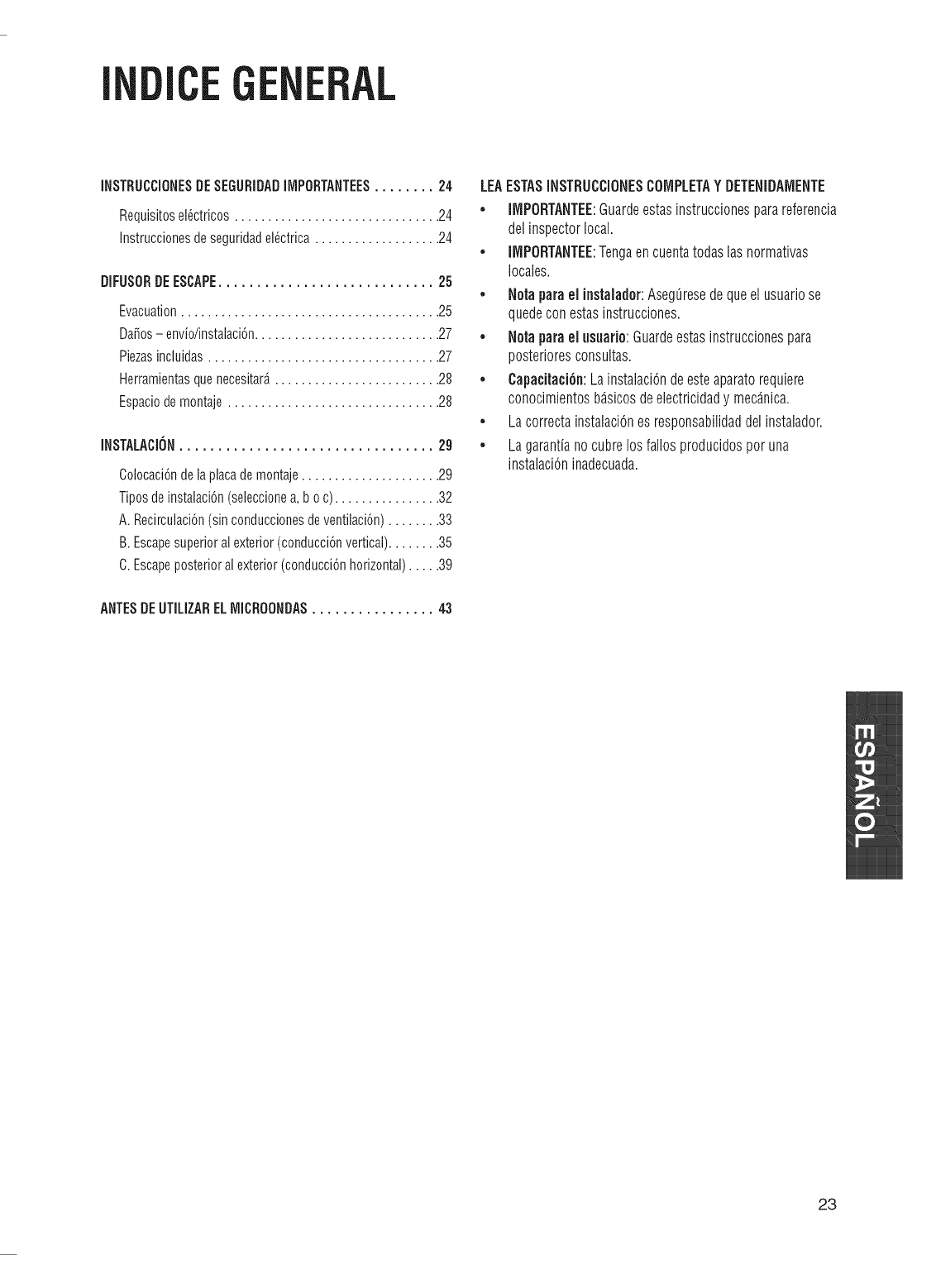
INSTRUCCIONESDESEGURIDADIMPORTANTEES........ 24
Requisitosei_ctricos............................... 24
Instruccionesdeseguridadel_ctrica................... 24
DIFUSORDEESCAPE............................ 25
Evacuation....................................... 25
Da_os- envio/instalaci6n............................ 27
Piezasincluidas................................... 27
Herramientasquenecesitar_......................... 28
Espaciodemontaje ................................ 28
INSTALACION................................. 2g
Colocaci6ndelaplacademontaje..................... 29
Tiposdeinstalaci6n(seleccionea, b o c) ................ 32
A. Recirculaci6n(sinconduccionesdeventilaci6n)........ 33
B. Escapesuperioral exterior(conducci6nvertical)........ 35
C.Escapeposterioralexterior(conducci6nhorizontal)..... 39
LEAESTASiNSTRUCCiONESCOiViPLETAYDETENIDAMENTE
* iMPORTANTEE:Guardeestasinstruccionesparareferencia
delinspectorlocal.
*iMPORTANTEE:Tengaencuentatodaslasnormativas
locales.
,Noraparaelinstalador:AsegQresedequeel usuariose
quedeconestasinstrucciones.
* Noraparael usuafio:Guardeestasinstruccionespara
posterioresconsultas.
,Capacitaci6n:LainstalaciOndeesteaparatorequiere
conocimientosb_.sicosdeelectricidady mec_.nica.
. LacorrectainstalaciOnesresponsabilidaddelinstalador.
. Lagarantianocubrelosfallosproducidosporuna
instalaciOninadecuada.
ANTESDE UTILIZARELMICROONDAS ................43
23
I
IUC U
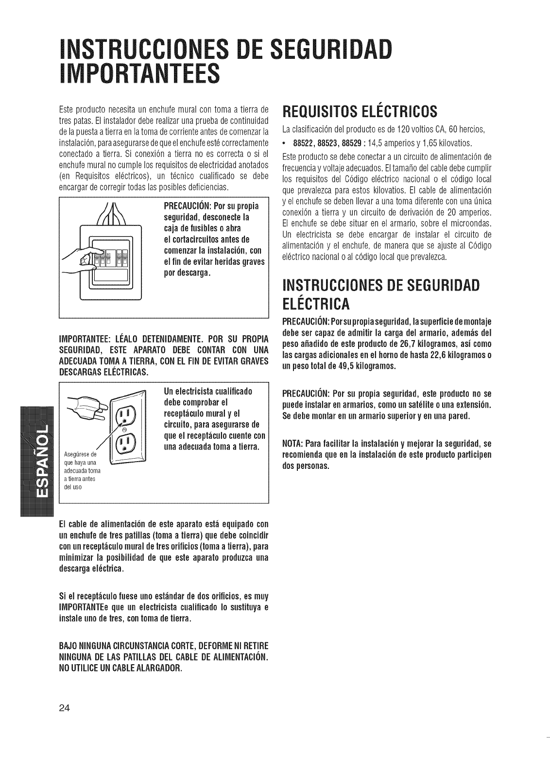
Esteproductonecesitaunenchufemuralcontomaa tierrade
trespatas.Elinstaladordeberealizarunapruebadecontinuidad
delapuestaatierraenlatomadecorrienteantesdecomenzarla
instalaciOn,paraasegurarsedequeelenchufeest_correctamente
conectadoa tierra.Si conexiOna tierra noes correctao si el
enchufemuralnocumplelosrequisitesdeelectricidadanotados
(en Requisitesel6ctricos),un t_cnico cualificadose debe
encargardecorregirtodaslasposiblesdeficiencias.
PRECAUCION:Persuprepia
segnridad,descouectela
cajadefusiblesoabra
elcortacircuitosantesde
cemenzarla instalaciGn,con
elfin deevitarheridasgraves
perdescarga.
iiViPORTANTEE:LI_ALODETENiDAIViENTE.PeR SU PROPIA
SEGURIDAD,ESTEAPARATODEBECONTARCON UNA
ADECUADATOiViAATiERRA,CONELFiNDEEViTARGRAVES
DESCARGASELI_CTRiCAS.
AsegOresede/__
que hayauna
adecuadatoma
atierraantes
del use
Uneiectricistacualificado
debecemprobarel
recept_cuiomuralyel
circuito,paraasegurarsede
qneelrecept_cuiecuentecon
unaadecuadatomaatierra.
REQUISITOSELI CTRICOS
LaclasificaciOndelproductoesde120voltiosCA,60hercios,
* 88522,88523,88529: 14,5amperiosy 1,65kilovatios.
Esteproductosedebeconectara uncircuitodealimentaciCnde
frecuenciay voltajeadecuados.Eltamaledelcabledebecumplir
los requisitesdel CCdigoelCctriconacionalo el cCdigolocal
queprevalezcaparaestoskilovatios.El cabledealimentaciCn
y elenchufesedebenIlevaraunatomadiferenteconuna_nica
conexiCna tierray uncircuitodederivaciCnde20 amperios.
Elenchufese debesituarenel armario,sobreel microondas.
Un electricistase debeencargarde instalarel circuito de
alimentaciCny el enchufe,de maneraquese ajusteal CCdigo
elCctriconacionaloalcCdigolocalqueprevalezca.
iNSTRUCCIONESDESEGURIDAD
ELi CTRiCA
PRECAUCiON:Persuprepiaseguridad,lasuperficiedemoutaje
debesetcapazdeadmitirla cargadelarmarie,adem_sdel
pesoafiadidedeestepreductode26,7 kilegramos,asi come
lascargasadicionaiesenel homodehasta22,6kiiegramose
unpesototalde49,5kiiegrames.
PRECAUCiON:Persu propiaseguridad,esteproductono se
puedeinstaiarenarmaries,comeunsat_iiteeunaextensiGn.
Sedebementarenunarmariesuperioryen unapared.
NOTA:Parafaciiitar la instalaciGny mejerarlaseguridad,se
recomiendaqueenla instalaciGndeestepreductoparticipen
despersonas.
ElcabledeaiimentaciGnde esteaparatoestdeqnipadocon
unenchufedeirespatiiias(tomaatierra)quedebeceincidir
conunrecept_cuiemuraldeiresorificies(tomaatierra),para
miuimizarla posibilidadde qneesteaparatopreduzcauna
descargael_ctrica.
Siel receptdcuJofueseuneestdndardedeserificios,esmuy
iiViPORTANTEeqneun electricistacualificadele sustituyae
instaleunodeires,contomadetierra.
BAJONiNGUNACIRCUNSTANCiACORTE,DEFORiViENi RETIRE
NiNGUNADELASPATiLLASDELCABLEDEALIiViENTACiON.
NOUTiLiCEUNCABLEALARGADOR.
24
iFU CAPE
EVACUATION
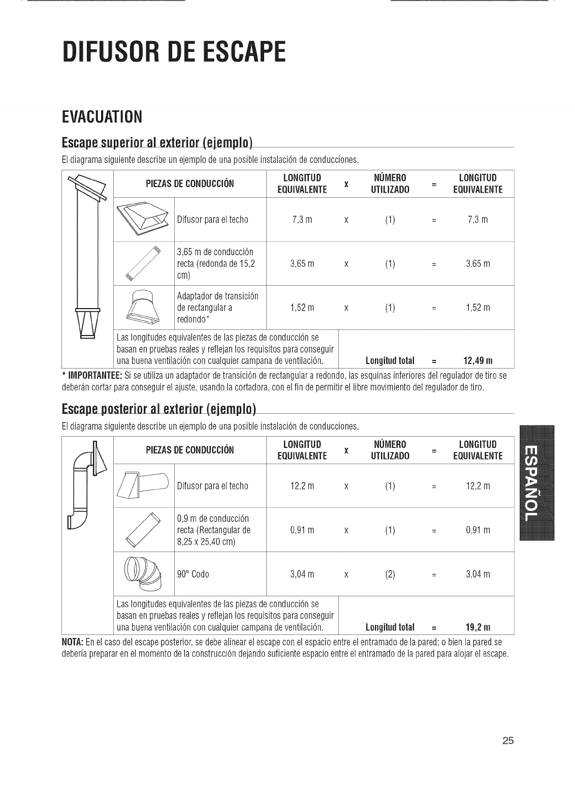
Escapesuperioral exterior ejemplo)
EldiagramasiguientedescribeunejemplodeunaposibleinstalaciOndeconducciones.
PIEZASDECONi)UCCION
Difusorparaeltecho
3,65mdeconducciOn
recta(redondade15,2
cm)
AdaptadordetransiciOn
derectangulara
redondo*
LONGiTUD NUiYiERO LONGiTUD
X =
EQUiVALENTE UTiLIZADO EQUiVALENTE
7,3m x (1) = 7,3 m
3,65m x (1) = 3,65m
1,52m x (1) = 1,52m
LaslongitudesequivalentesdelaspiezasdeconducciOnse
basanenpruebasrealesy reflejanlosrequisitosparaconseguir
unabuenaventilaciOnconcualquiercampanadeventilaciOn. Longitudtotal = 12,49m
iMPORTANTEE:SiseutilizaunadaptadordetransiciOnderectangulararedondo,lasesquinasinferioresdelreguladordetiro se
deber_.ncortarparaconseguirelajuste,usandolacortadora,conelfin depermitirellibremovimientodelreguladordetiro.
Escapeposterioral exterior(ejemplo)
EldiagramasiguientedescribeunejempiodeunaposibleinstalaciOndeconducciones.
[L;
PIEZASDECONi)UCCION LONGiTUi) NUiYiERO LONGiTUi)
X =
EQUiVALENTE UTiLIZADO EQUiVALENTE
Difusorparaeltecho
0,9rndeconducciOn
recta(Rectangularde
8,25x 25,40cm)
900Codo
12,2m x (1) = 12,2m
0,91m x (1) = 0,91m
3,04m x (2) = 3,04m
LaslongitudesequivalentesdelaspiezasdeconducciOnse
basanenpruebasrealesy reflejanlosrequisitosparaconseguir
unabuenaventilaciOnconcualquiercampanadeventilaciOn. Longitudtotal = 19,2m
NOTA:Enelcasodelescapeposterior,sedebealinearelescapeconelespacioentreelentramadodelapared;o bienlaparedse
deberiaprepararenelmomentodelaconstrucciOndejandosuficienteespacioentreelentramadodelaparedparaalojarelescape.
25
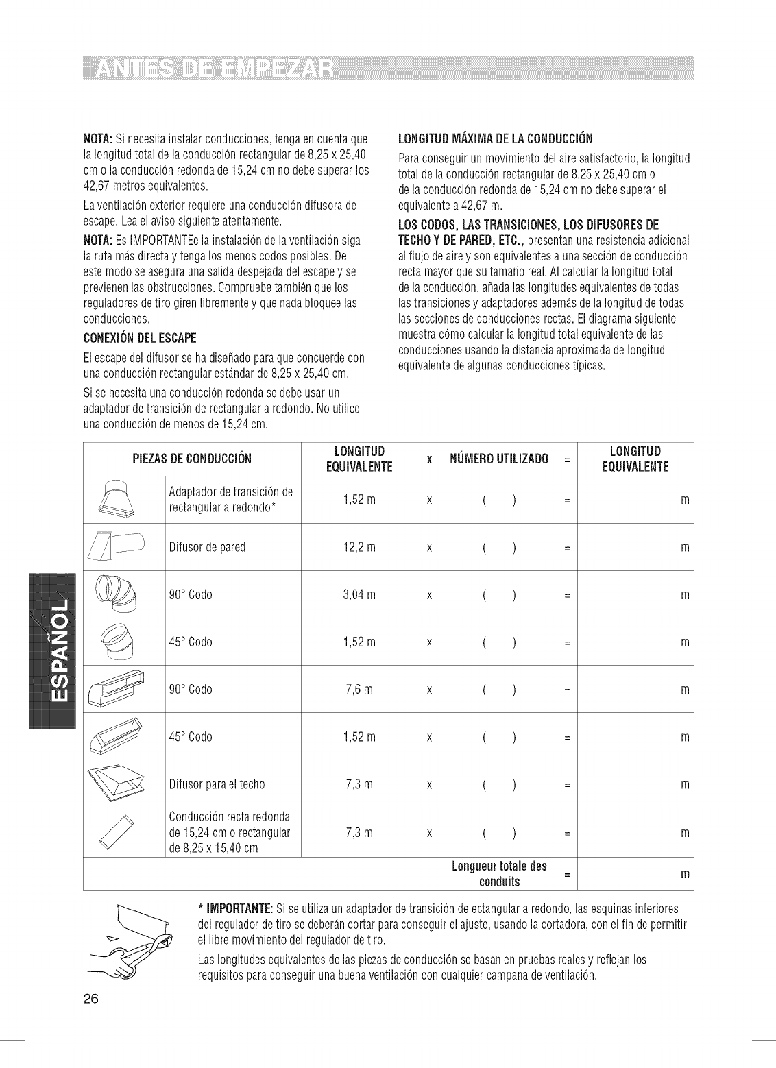
NOTA:Sinecesitainstalarconducciones,tengaencuentaque
laIongitudtotaldelaconducciOnrectangularde8,25x25,40
cmolaconducciOnredondade15,24cmnodebesuperarlos
42,67metrosequivalentes.
LaventilaciOnexteriorrequiereunaconducciOndifusorade
escape.Leaelavisosiguienteatentamente.
NOTA:EsIMPORTANTEelainstalaciOndelaventilaciOnsiga
larutam_.sdirectaytengalosmenoscodosposibles.De
estemodoseaseguraunasalidadespejadadelescapeyse
previenenlasobstrucciones.Compruebetambi6nquelos
reguladoresdetirogirenlibrementeyquenadabloqueelas
conducciones.
CONEXIONDELESCAPE
Elescapedeldifusorsehadise_adoparaqueconcuerdecon
unaconducciOnrectangularest_.ndarde8,25x 25,40cm.
SisenecesitaunaconducciOnredondasedebeusarun
adaptadordetransiciOnderectangulara redondo.Noutilice
unaconducciOndemenosde15,24cm.
LONGITUDMAXIMADELACONDUCCION
Paraconseguirunmovimientodelairesatisfactorio,laIongitud
totaldelaconducciOnrectangularde8,25x 25,40cmo
delaconducciOnredondade15,24cmnodebesuperarel
equivalentea42,67m.
LOSCODOS,LASTRANSiCiONES,LOSDIFUSORESDE
TECHOYDEPARED,ETC.,presentanunaresistenciaadicional
alflujodeairey sonequivalentesaunasecciOndeconducciOn
rectamayorquesutama_oreal.AIcalcularlaIongitudtotal
delaconducciOn,a_adalaslongitudesequivalentesdetodas
lastransicionesy adaptadoresadem_.sdelaIongituddetodas
lasseccionesdeconduccionesrectas.Eldiagramasiguiente
muestracOmocalcularlaIongitudtotalequivalentedelas
conduccionesusandoladistanciaaproximadadeIongitud
equivalentedealgunasconduccionestipicas.
PIEZASDECONDUCCiON LONGiTUD x NUMERO UTiLIZADO= LONGiTUD
EQUIVALENTE EGUIVALENTE
AdaptadordetransiciOnde 1,52m x ( ) = m
rectangulararedondo*
Difusordepared 12,2m x ( ) = m
900Codo 3,04m x ( ) =m
__ 1,52m x ( ) = m
45oCodo
7,6m x ( ) = m
900Codo
450Codo 1,52m x ( ) = m
Difusorparaeltecho 7,3m x ( ) = m
ConducciOnrectaredonda
de15,24cmo rectangular 7,3m x ( ) = m
de8,25x 15,40cm
Longueurtotaledes =nl
conduits
*IIVIPORTANTE:SiseutilizaunadaptadordetransiciOndeectangulararedondo,lasesquinasinferiores
delreguladordetirosedeber_.ncortarparaconseguirelajuste,usandolacortadora,conelfin depermitir
ellibremovimientodelreguladordetiro.
LaslongitudesequivalentesdelaspiezasdeconducciOnsebasanenpruebasrealesy reflejanlos
requisitosparaconseguirunabuenaventilaciOnconcualquiercampanadeventilaciOn.
26
DANOS- ENVJO/INSTALACi6N
*Sila unidadsedafiaenel envie,comuniqueseconlatiendadondelacomprO,oconel1-800-4-MY-HOME®.
* Siel ¢lientehadanadela unidad,lareparaci6nosustituci6nser_.responsabilidaddelcliente.
* Siel instaladorhadanadolaunidad(si nehasideel¢liente),lareparaci6nolasustituci6nsedeberealizarmediante
acuerdoentreclienteeinstalador.
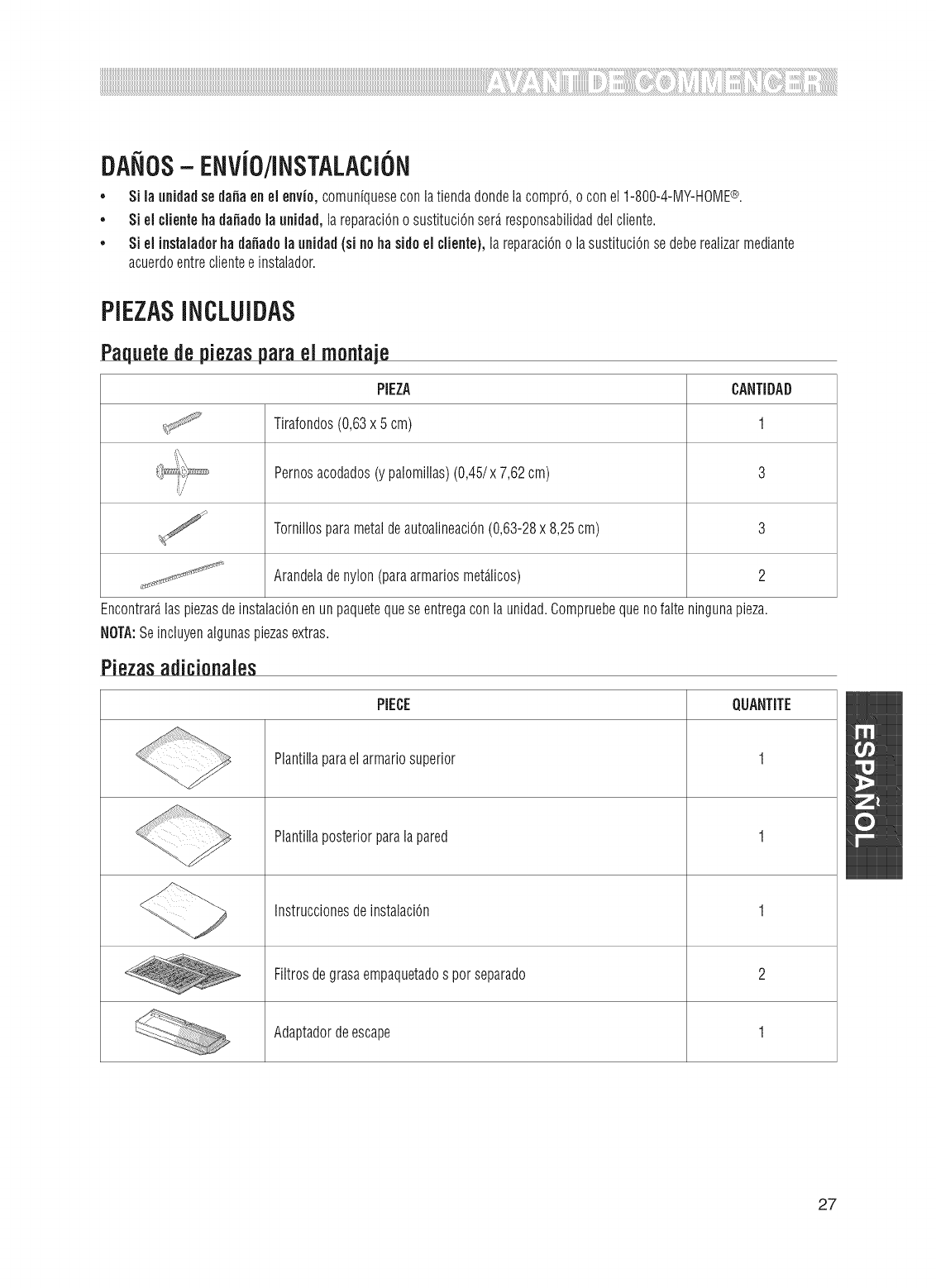
PiEZASINCLUiDAS
Paquetede piezaspareei montaje
PiEZA CANTiDAD
Tirafondos(0,63x 5cm) 1
Pernosacodados(y palomillas)(0,45/x7,62cm) 3
:/
Tornillosparametaldeautoalineaci6n(0,63-28x 8,25cm) 3
Arandeladenylon(paraarmariosmet_.licos) 2
Encontrar_.laspiezasdeinstalaci6nenunpaquetequeseentregaconlaunidad.Compruebequenofalteningunapieza.
NOTA:Seincluyenalgunaspiezasextras.
Piezasadicionales
PIECE QUANTiTE
Plantillaparaelarmariosuperior 1
Plantillaposteriorparalapared 1
Instruccionesdeinstalaci6n 1
__ grasaempaquetados perseparado
Filtrosde 2
Adaptadordeescape 1
27
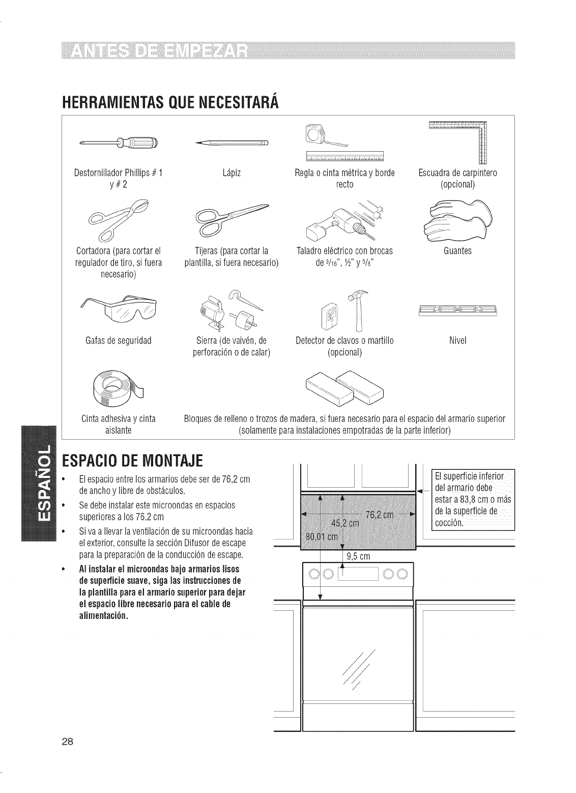
HERRAMiENTASQUENECESiTARA
DestornilladorPhillips# 1 L@iz
y#2
Cortadora(parecortarel
reguladordetire,si fuera
necesario)
Gafasdeseguridad
Tijeras(parecortarla
plantilla,si fueranecesario)
Sierra(devaiv@,de
perforaciOnodecalar
Reglaocintam6tricay borde
recto
Taladroel6ctricoconbrocas
des/16",1A"y 5/8"
Detectordeclavosomartillo
(opcional)
Escuadradecarpintero
(opcional)
Guantes
Nivel
Cintaadhesivey cinta
aislante BIoquesderellenootrozosdemadera,si fueranecesarioparaelespaciodelarmariosuperior
(solamenteparainstalacionesempotradasdelaparteinferior)
ESPACIODEIViONTAJE
• Elespacioentrelosarmariosdebeserde76,2cm
deanchoy fibredeobst_.culos.
• Sedebeinstalarestemicroondasenespacios
superioresalos76,2cm
• SivaaIlevarlaventilaciOndesu microondashacia
elexterior,consultelasecciOnDifusordeescape
paralapreparaciOndelaconducciOndeescape.
•AIiustalarel micreondasbajoarmarioslisos
desuperficiesuave,sigalos iustruccieuesde
lapiautiilapareel armariesuperiorparedejar
elespacielibreuecesariepareel cablede
alimentaci6u.
ElsupeEficieiufedo[
delarmariodebe I
esta[a83,8cmom_.s
deiasuperficbde
COCCiOn,
28
I
COLOCACiONDELAPLACADE
iVlONTAJE
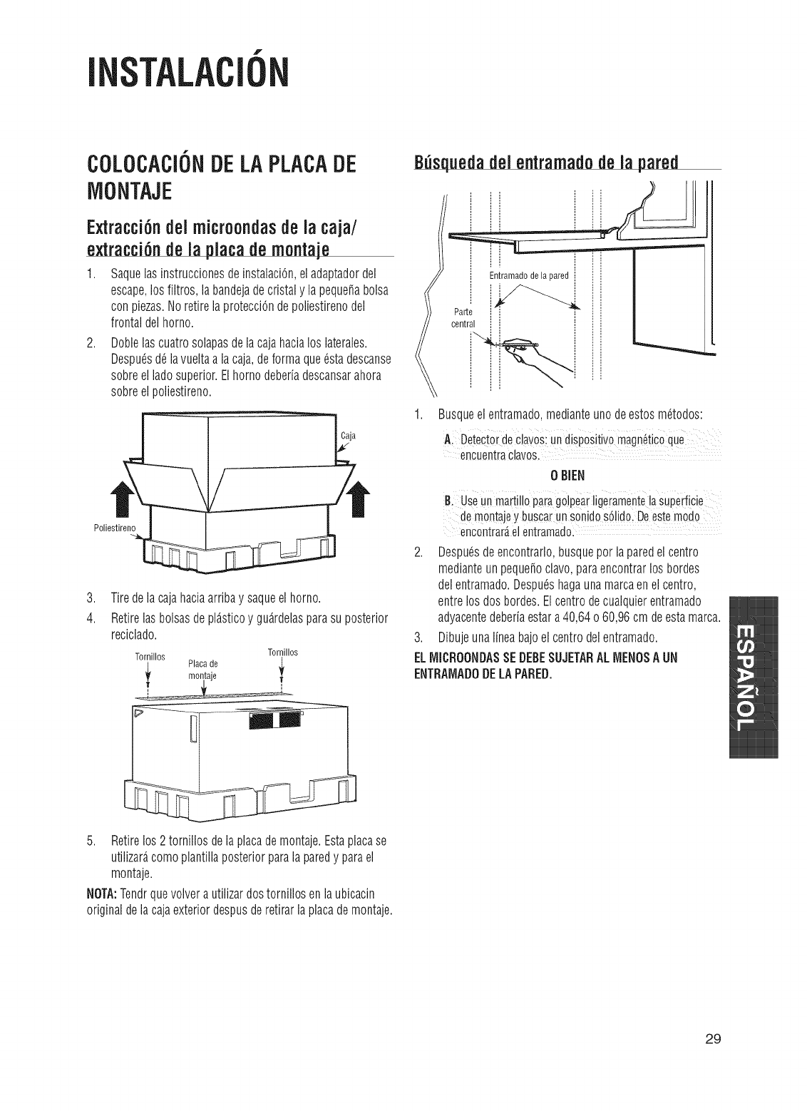
Extracci6ndel microondasde la caja/
extracci6nde la piacademontaje
1. Saquelasinstruccionesdeinstalaci6n,eladaptadordel
escape,losfiltros,labandejadecristaly lapeque_abolsa
conpiezas.NoretirelaprotecciOndepoliestirenodel
frontaldelhorno.
2. Doblelascuatrosolapasdelacajahacialos laterales.
Despu6sd6lavueltaalacaja,deformaque6stadescanse
sobreelladosuperior.Elhornodeberiadescansarahora
sobreelpoliestireno.
Caja
Poliestireno
,
4.
Tiredelacajahaciaarribay saqueelhorno.
Retirelasbolsasdepl_.sticoy gu_.rdelasparasu posterior
reciclado.
Tornillos Tornillos
,_ Placade
montaje
B_squedadel entramadode la pared
Parte
central
Entramadodela pared
1. Busqueelentramado,medianteunodeestosm6todos:
A DetectOrdeCla_osiundispositivomagnetic0que
encuentraclavos,
0 BIEN
useunmait_"oparag_eaiiigeiameote_a
de montajey buscarunsonidos6iido,Deestemodo
encontrar_elentramadol
2. Despu6sdeencontrarlo,busqueporlaparedelcentro
medianteunpeque_oclavo,paraencontrarlos bordes
delentramado.Despu6shagaunamarcaenel centro,
entrelosdosbordes.Elcentrodecualquierentramado
adyacentedeberiaestara40,64o60,96cmdeestamarca.
3. Dibujeunalineabajoelcentrodelentramado.
ELMICROONDASSEDEBESUJETARALMENOSA UN
ENTRAMADODELAPARED.
5. Retirelos2tornillosdelaplacademontaje.Estaplacase
utilizar_,comoplantillaposteriorparalaparedy parael
montaje.
NOTA:Tendrquevolverautilizardostornillosenlaubicacin
originaldelacajaexteriordespusderetirarlaplacademontaje.
29
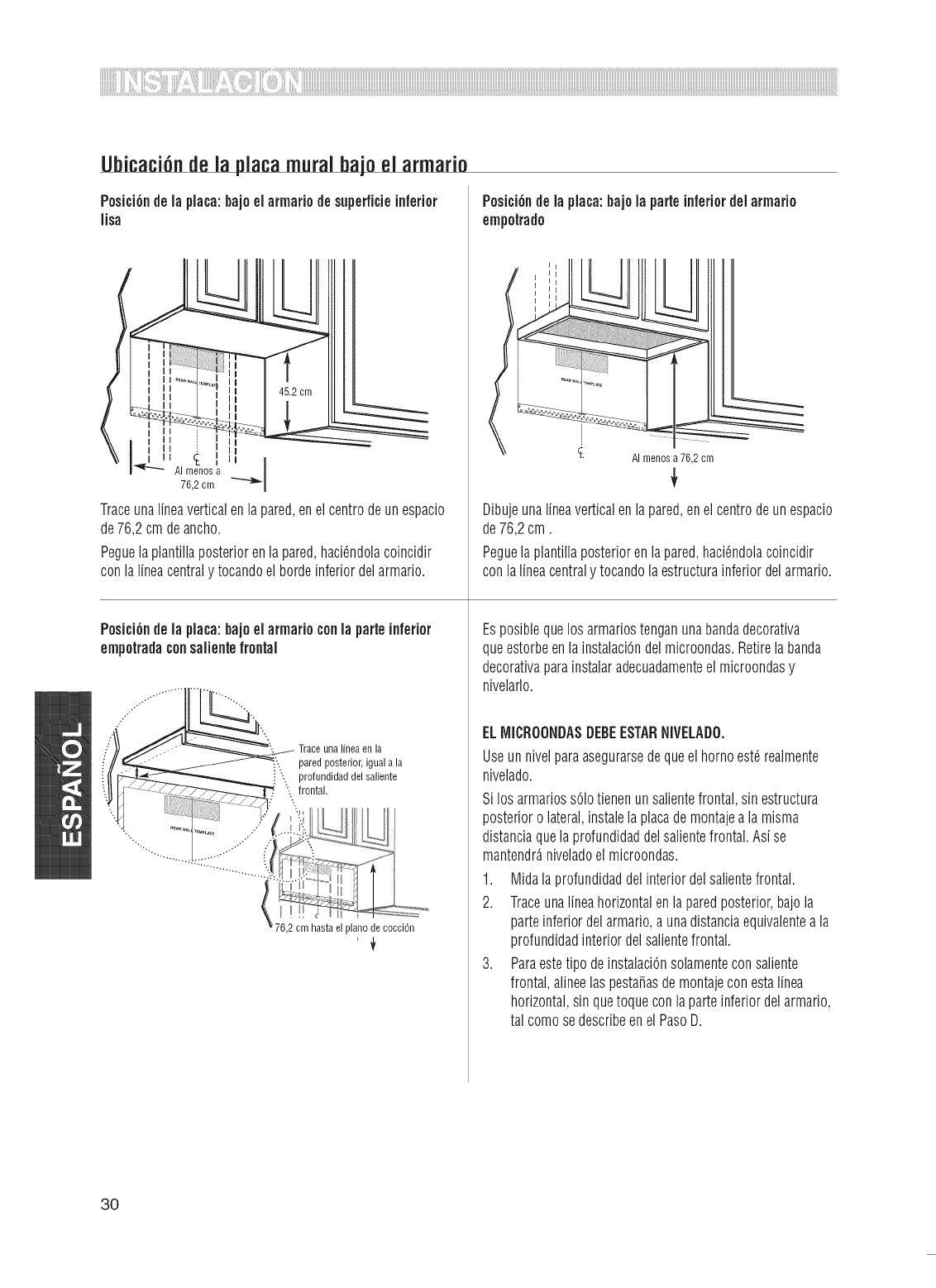
UbicaciOnde la placamural bajoel armario
PesiciOndela placa:bajeel armariedesnpe#icieinferior
lisa
Traceunalineaverticalenlapared,enelcentredeunespacio
de76,2cmdeancho.
Peguelaplantillaposteriorenlapared,haciOndolacoincidir
conlalineacentraly tocandoelbordeinferiordelarmario.
PositiOndela plata:bajoel armarieconla parteinferior
empetradaconsalientefrontal
Traceuna lineaen la
paredposterior,iguala la
i_ profundidaddel saliente
;._ frontal.
PosiciOndelaplaca:bajela parteinferiordelarmarie
empetrado
76,2 cm hastael planedecocci6n
J
AI menosa76,2 cm
Dibujeunalineaverticalenlapared,enelcentredeunespacio
de76,2cm.
Peguelaplantillaposteriorenlapared,haciOndolacoincidir
conlalineacentraly tocandolaestructurainferiordelarmario.
Esposiblequelosarmariostenganunabandadecorativa
queestorbeenlainstalaciOndelmicroondas.Retirelabanda
decorativaparainstalaradecuadamenteelmicroondasy
nivelarlo.
ELiViiCROONDASDEBEESTARNiVELADO.
Useunnivelparaasegurarsedequeelhornoest_realmente
nivelado.
Silosarmariossolotienenunsalientefrontal,sinestructura
posterioro lateral,instalelaplacademontajealamisma
distanciaquelaprofundidaddelsalientefrontal.Asise
mantendr_,niveladoelmicroondas.
1. Midalaprofundidaddelinteriordelsalientefrontal.
2. Traceunalineahorizontalenlaparedposterior,bajola
parteinferiordelarmario,a unadistanciaequivalenteala
profundidadinteriordelsalientefrontal.
3. ParaestetipodeinstalaciOnsolamenteconsaliente
frontal,alineelaspesta_asdemontajeconestalinea
horizontal,sinquetoqueconlaparteinferiordelarmario,
tal comesedescribeenel PasoD.
3O
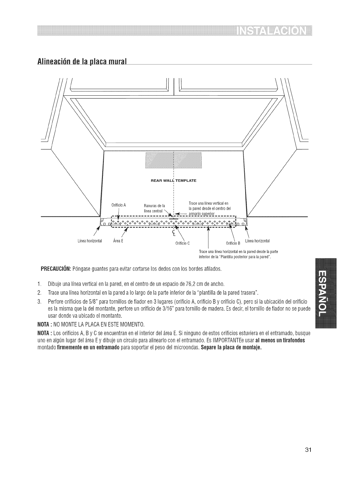
Alineaci ndela platamural
REAR WALL_ TEMPLATE
OdficioA Traceunalineavertical en
Ranurasde la la pareddesdeelcentro del
lineacentral _,_i_,_ _-- armariosuperior
ooooooo
Lineahorizontal _,reaE Lineahorizontal
Odficio C Odficio B
Traceuna lineahorizontalen lapared desdela parte
inferiordela "Plantilla posteriorparala pared".
PRECAUCION:POngaseguantesparaevitarcortarselos dedosconlosbordesafilados.
1. Dibujeunalineaverticalenlapared,enelcentrodeunespaciode76,2cmdeancho.
2. TraceunalineahorizontalenlaparedaIo largodelaparteinferiordela"plantilladelaparedtrasera".
3. Perforeorificiosde5/8"paratornillosdefiadoren3lugares(orificioA,orificioBy orificioC),perosi laubicaci6ndelorificio
esla mismaqueladelmontante,perforeunorificiode3/16"paratornillodemadera.Esdecir,eltornillodefiadornosepuede
usardondevaubicadoelmontante.
NOTA: NOMONTELAPLACAENESTEMOMENTO.
NOTA: LosorificiosA,By Cseencuentranenelinteriordel_.reaE.Siningunodeestosorificiosestuvieraenelentramado,busque
unoenalg_nlugardel_.reaEy dibujeuncirculoparaalinearloconelentramado.EsIMPORTANTEeusaral menosnntirafondos
montadofirmementeennnentramadoparasoportarelpesodelmicroondas.Separelaplacademontaje.
31
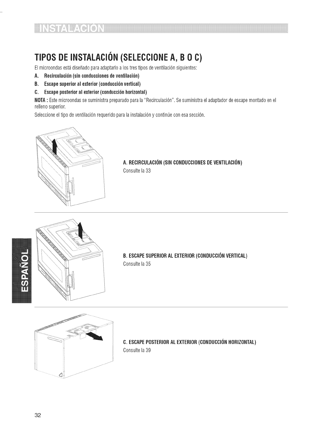
TiPOSDEINSTALACiON(SELECCiOHEA, B0 C)
Elmicroondasest,.dise_adoparaadaptarloalostrestiposdeventilaciOnsiguientes:
A. Recirculaci6n(sincenduccienesdeventilaci6n)
B, Escapesuperioral exterior(cenducci6nvertical)
C. Escapeposterioral exterior(cenducci6nhorizontal)
NOTA: Estemicroondassesuministrapreparadoparala"RecirculaciOn".Sesuministraeladaptadordeescapemontadoenel
rellenosuperior.
Seleccioneeltipo deventilaciOnrequeridoparalainstalaciOny continOeconesasecciOn.
A, RECiRCULACi6N(SiNCONDUCCiONESDEVENTiLACi6N)
Consultela33
B,ESCAPESUPERIORALEXTERIOR(COHDUCCi6HVERTICAL)
Consultela35
C,ESCAPEPOSTERIORALEXTERIOR(CONDUCCi6NHORIZONTAL)
Consultela39
32
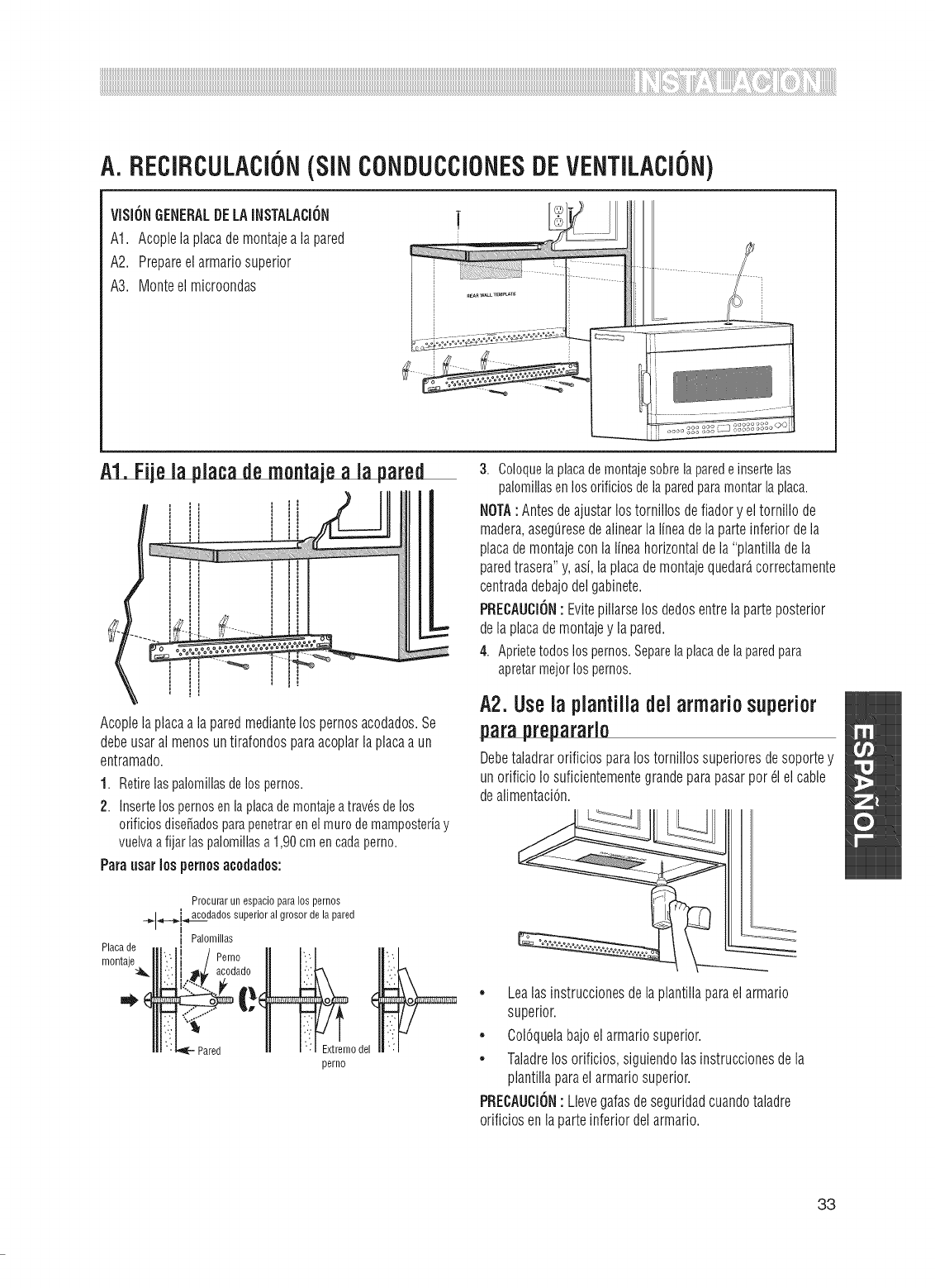
A=
VISIONGENERALDELAINSTALACION
A1. Acoplelaplacademontajea lapared
A2. Prepareelarmariosuperior
A3. Monteelmicroondas
RECiRCULACiON(SiNCONDUCCiONESDEVENTiLACiON)
l
Acoplelaplacaalaparedmediantelospernosacodados.Se
debeusaralmenosuntirafondosparaacoplarlaplacaa un
entramado.
1. Retirelaspalomillasdelospernos.
2. InsertelospernosenlaplacademontajeatravSsdelos
orificiosdise_adosparapenetrarenelmurodemamposteriay
vuelvaafijarlaspalomillasa1,90cmencadaperno.
Pardosarlosperoosacodados:
Procurarun espacioparalos pernos
__..,_dados superioral grosor de la pared
i Palomillas
Placade
montaje )_
_odel
perno
3. Coloquelaplacademontajesobrelaparedeinsertelas
palomillasenlosorificiosdelaparedparamontarlaplaca.
NOTA:Antesdeajustarlostornillosdefiadory eltornillode
madera,aseg[iresedealinearlalineadelaparteinferiordela
placademontajeconlalineahorizontaldela"plantilladela
paredtrasera"y,asi,laplacademontajequedar_,correctamente
centradadebajodelgabinete.
PRECAUCION: Evitepillarselosdedosentrelaparteposterior
delaplacademontajey lapared.
4. Aprietetodoslospernos.Separelaplacadelaparedpara
apretarmejorlospernos.
A2. Usela plantilladel armario superior
pardprepararla
Debetaladrarorificiosparalostornillossuperioresdesoportey
unorificioIo suficientementegrandeparapasarpor_1elcable
dealimentaciOn.
• Lealasinstruccionesdeiaplantillaparaelarmario
superior.
• ColOquelabajoelarmariosuperior.
• Taladrelosorificios,siguiendolasinstruccionesdela
plantillaparaelarmariosuperior.
PRECAUCION: Llevegafasdeseguridadcuandotaladre
orificiosenlaparteinferiordelarmario.
33
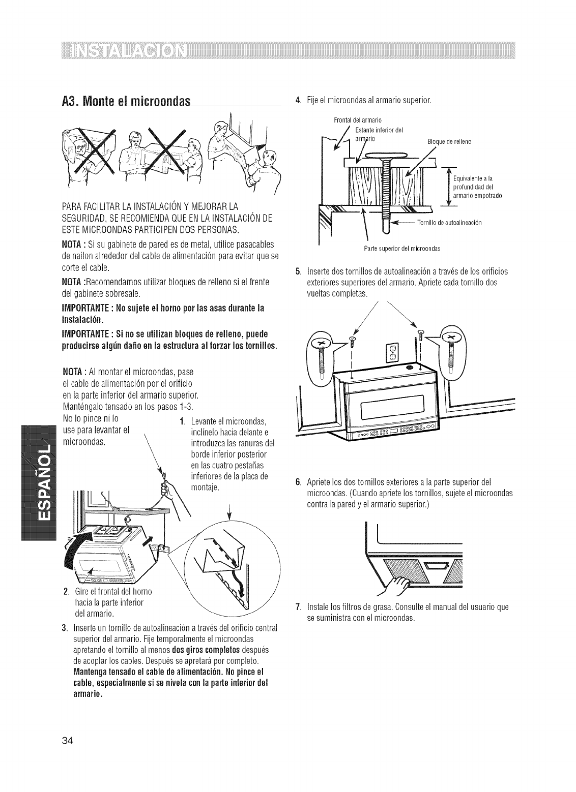
A3. Monteel microondas 4.
PARAFACILITARLA INSTALACIONY MEJORARLA
SEGURIDAD,SE RECOMIENDAQUEENLAINSTALACIONDE
ESTEIVIICROONDASPARTICIPENDOSPERSONAS.
NOTA: Si su gabinetede paredes demetal,utilice pasacables
de nailonalrededordel cablede alimentaci6npara evitar quese
corteel cable. 5.
NOTA:Recomendamosutilizar bloquesderellenosi el frente
del gabinetesobresale.
IMPORTANTE:Nosujeteel homoperlas asasdurante la
instalaci6n.
iiViPORTANTE: Si nose utilizanblequesde rellene, puede
preducirsealgtin dane enla estructuraal ferzar los tornilles.
NOTA: AI montarel microondas,pase
el cabledealimentaci6nper el orificio /
en la parteinferior del armariosuperior, t_
IVlant6ngalotensadoenlos pasos 1-3.
NoIo pinceni Io 1. Levanteel microondas,
useparalevantarel inclinelohaciadelantee
microondas, introduzcalasranurasdel
bordeinferiorposterior
enlascuatropesta_as
inferioresdela placade 6.
montaje.
2. Gireelfrontaldelhomo
haciala parteinferior
del armario.
3. Inserteun tornillo deautoalineaci6na trav_sdel orificiocentral
superiordel armario.Fijetemporalmenteelmicroondas
apretandoeltornillo almenosdos giroscompletesdespu_s
deacoplarloscables.Despu_sseapretar_percomplete.
Mantengatensadoel cablede alimentaci6n.Nopinceel
cable, especialmentesi senivelaconla parte inferior del
armario.
Fijeel microondasai armariosuperior.
Frontaldelarmario
Estanteinferiordel
Lrio Bloquede relleno
qUivalentea la
rofundidaddel
marie empotrado
deautoalineaci6n
Partesuperiordel microondas
Insertedostornillosdeautoalineaci6na trav_sde losorificios
exterioressuperioresdelarmario.Aprietecadatornillo dos
vueltascompletas.
/\
Aprietelosdostornillosexterioresa lapartesuperiordel
microondas.(Cuandoaprietelostornillos,sujeteel microondas
contralaparedy elarmariosuperior.)
\
7. Instalelosfiltrosde grasa.Consulteelmanualdel usuarioque
se suministraconel microondas.
34
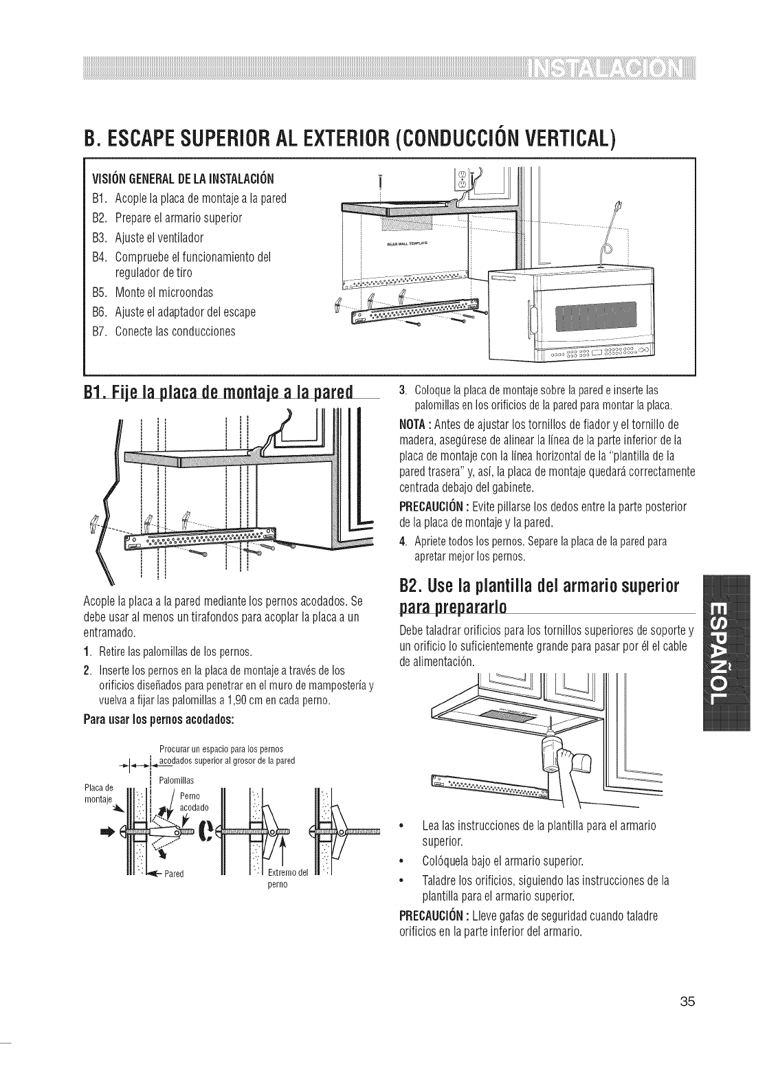
B.ESCAPESUPERIORALEXTERIOR(CONDUCCiONVERTICAL)
VISION6ENERALDELAINSTALACI6N
B1. Acoplelaplacademontajea lapared
B2. Prepareelarmariosuperior
B3. Ajusteelventilador
B4. Compruebeelfuncionamientodel
reguladordetiro
B5. Monteelmicroondas
B6. Ajusteeladaptadordelescape
B7. Conectelasconducciones
Acoplelaplacaalaparedmediantelospernosacodados.Se
debeusaralmenosuntirafondosparaacoplarlaplacaa un
entramado.
1. Retirelaspalomillasdelospernos.
2. InsertelospernosenlaplacademontajeatravSsdelos
orificiosdise_adosparapenetrarenelmurodemamposteriay
vuelvaafijarlaspalomillasa1,90cmencadaperno.
Paraosarlospernosacodados:
Procurarun espacioparalos pernos
__..,_dados superioral grosor de la pared
i Palomillas
Placade
montaje )_
_odel
perno
3. Coloquelaplacademontajesobrelaparedeinsertelas
palomillasenlosorificiosdelaparedparamontarlaplaca.
NOTA:Antesdeajustarlostornillosdefiadory eltornillode
madera,aseg[iresedealinearlalineadelaparteinferiordela
placademontajeconlalineahorizontaldela"plantilladela
paredtrasera"y,asi,laplacademontajequedar_,correctamente
centradadebajodelgabinete.
PRECAUCION: Evitepillarselosdedosentrelaparteposterior
delaplacademontajey lapared.
4. Aprietetodoslospernos.Separelaplacadelaparedpara
apretarmejorlospernos.
B2.Usela planiilladel armario superior
paraprepararlo
Debetaladrarorificiosparalostornillossuperioresdesoportey
unorificioIo suficientementegrandeparapasarpor_lelcable
dealimentaciOn.
• Lealasinstruccionesdelaplantillaparaelarmario
superior.
• ColOquelabajoelarmariosuperior.
• Taladrelosorificios,siguiendolasinstruccionesdela
plantillaparaelarmariosuperior.
PREOAUO[ON: Llevegafasdeseguridadcuandotaladre
orificiosenlaparteinferiordelarmario.
35
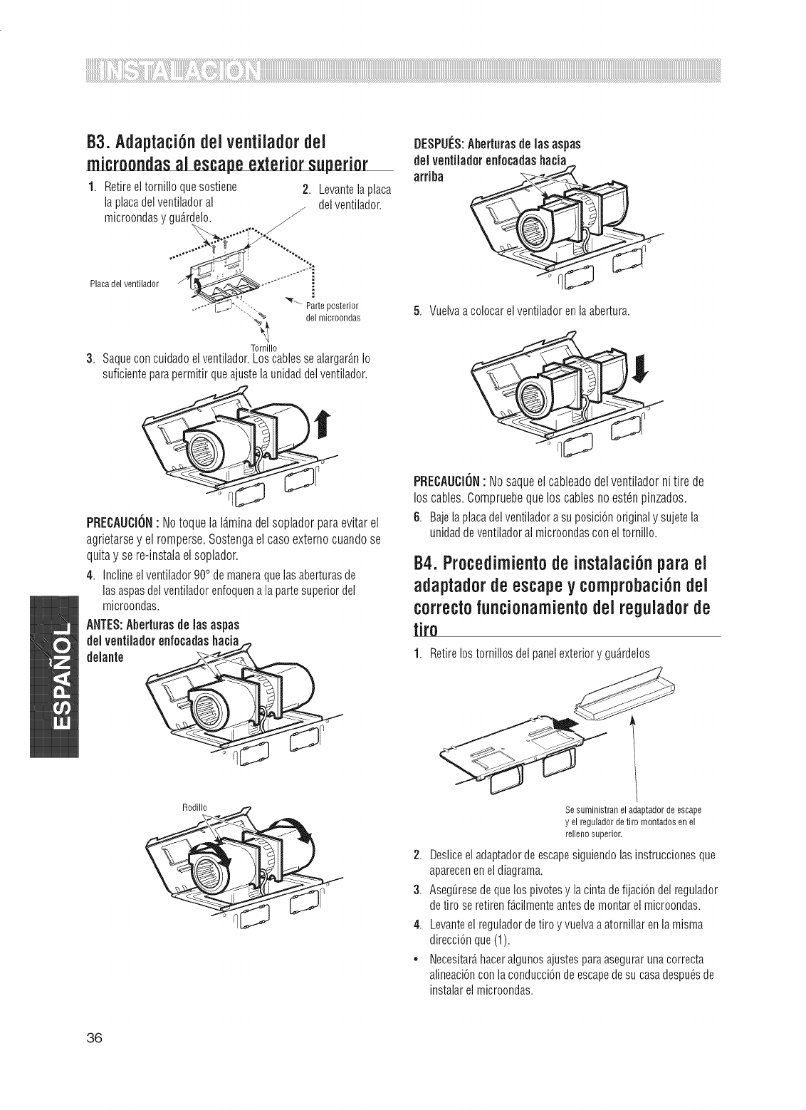
B3.Adaptaci6ndel ventiladordel
microondasal escapeexteriorsuperior
1. Retireeltornillo quesostiene 2. Levantelaplaca
la placadelventiladoral /del ventilador.
microondasygu_rdelo.
Placadel ventilador
Parteposterior
"'-_ del microondas
Tornillo
3. Saque con cuidado el ventilador.Los cables se alargarfin Io
suficienteparapermitir queajustela unidaddelventilador.
DESPUES:Aberturasdelasaspas
delventiladorenfecadashacia
arriba
5. Vuelvaa colocarel ventiladoren la abertura.
PRECAUCION: Notoque la I_.minadel soplador paraevitar el
agrietarsey el romperse.Sostengael casoexterno cuandose
quitay se re-instalael soplador.
4. Inclineelventilador900demaneraquelasaberturasde
lasaspasdelventiladorenfoquena lapartesuperiordel
microondas.
ANTES:Aberturas de lasaspas
del ventiladorenfecadashacia
delante _"_ .
PRECAUCiON: Nosaqueelcableadodelventiladornitire de
loscables.Compruebequeloscablesnoest_npinzados.
6. Bajelaplacadelventiladorasuposici6noriginaly sujetela
unidaddeventiladoralmicroondasconeltornillo.
B4.Procedirnientode instalaci6npara el
adaptadorde escapey comprobaci6ndel
correctofuncionamientodel reguiadorde
tire
1. Retirelostornillosdel panelexteriory gu_rdelos
Sesuministranel adaptadordeescape
y el reguladordetiro montadosen el
rellenosuperior.
2. Desliceel adaptadorde escapesiguiendolasinstruccionesque
apareceneneldiagrama.
3. Aseg_resede quelos pivotesy la cintadefijaci6ndel regulador
detiro se retirenf_cilmenteantesdemontarel microondas.
4. Levanteel reguladordetiroy vuelvaaatornillarenla misma
direcci6nque(1).
• Necesitar_haceralgunosajustesparaasegurarunacorrecta
alineaci6nconlaconducci6ndeescapedesu casadespu_sde
instalarel microondas.
36
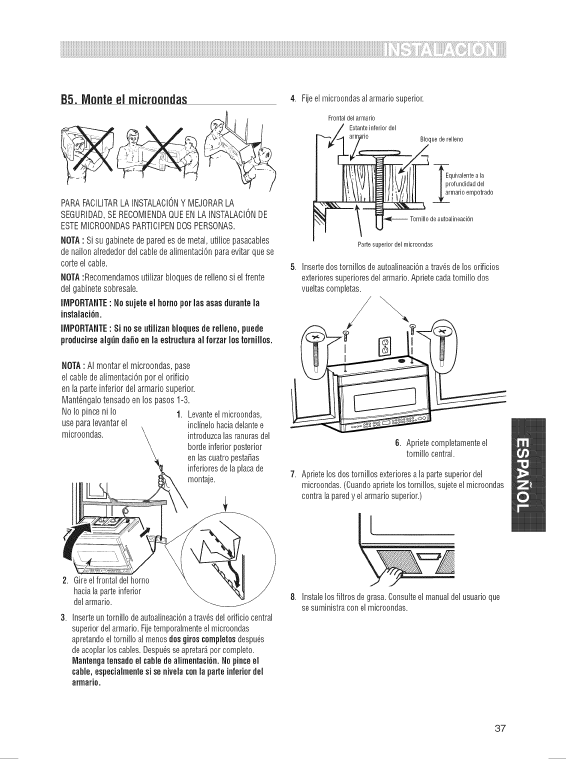
85. Monteel microondas 4.
PARAFACILITARLA INSTALACIONY MEJORARLA
SEGURIDAD,SE RECOMIENDAQUEENLAINSTALACIONDE
ESTEIVIICROONDASPARTICIPENDOSPERSONAS.
NOTA: Si su gabinetede paredes demetal,utilice pasacables
de nailonalrededordel cablede alimentaci6npara evitar quese
corteel cable. 5.
NOTA:Recomendamosutilizar bloquesderellenosi el frente
del gabinetesobresale.
_MPORTANTE:Nosujeteel homoperlas asasd_rante la
instalaci6n.
iiViPORTANTE: Si nose utiiizanblequesde rellene, puede
preducirsealgtin da_e enla estructuraal ferzar los families.
NOTA: AI montarel microondas,pase
el cabledealimentaci6nper el orificio
en la parteinferior del armariosuperior.
IVlant_ngalotensadoenlos pasos 1-3.
NoIo pinceni Io 1. Levanteel microondas,
useparalevantarel inclinelohaciadelantee
microondas, introduzcalasranurasdel
bordeinferiorposterior
enlascuatropesta_as
inferioresdela placade
montaje.
2. Gireelfrontaldelhomo
haciala parteinferior
del armario.
3. Inserteun tornillo deautoalineaci6na trav_sdel orificiocentral
superiordel armario.Fijetemporalmenteelmicroondas
apretandoeltornillo almenosdos giroscompletesdespu_s
deacoplarloscables.Despu_sseapretar_percomplete.
Mantengatensadoel cablede alimentaci6n.Nopinceel
cable, especialmentesi senivelaconla parte inferior del
armario.
Fijeel microondasai armariosuperior.
Frontaldelarmario
Estanteinferiordel
_rio Bloquede relleno
-_a_rqUivalentea la
rofundidaddel
marie empotrado
deautoalineaci6n
Partesuperiordel microondas
Insertedostornillosdeautoalineaci6na trav_sde losorificios
exterioressuperioresdelarmario.Aprietecadatornillo dos
vueltascompletas.
/
6. Aprietecompletamenteel
tornillo central.
Aprietelosdostornillosexterioresa lapartesuperiordel
microondas.(Cuandoaprietelostornillos,sujeteel microondas
contralaparedy elarmariosuperior.)
8. Instalelosfiltrosde grasa.Consulteelmanualdel usuarioque
se suministraconel microondas.
37
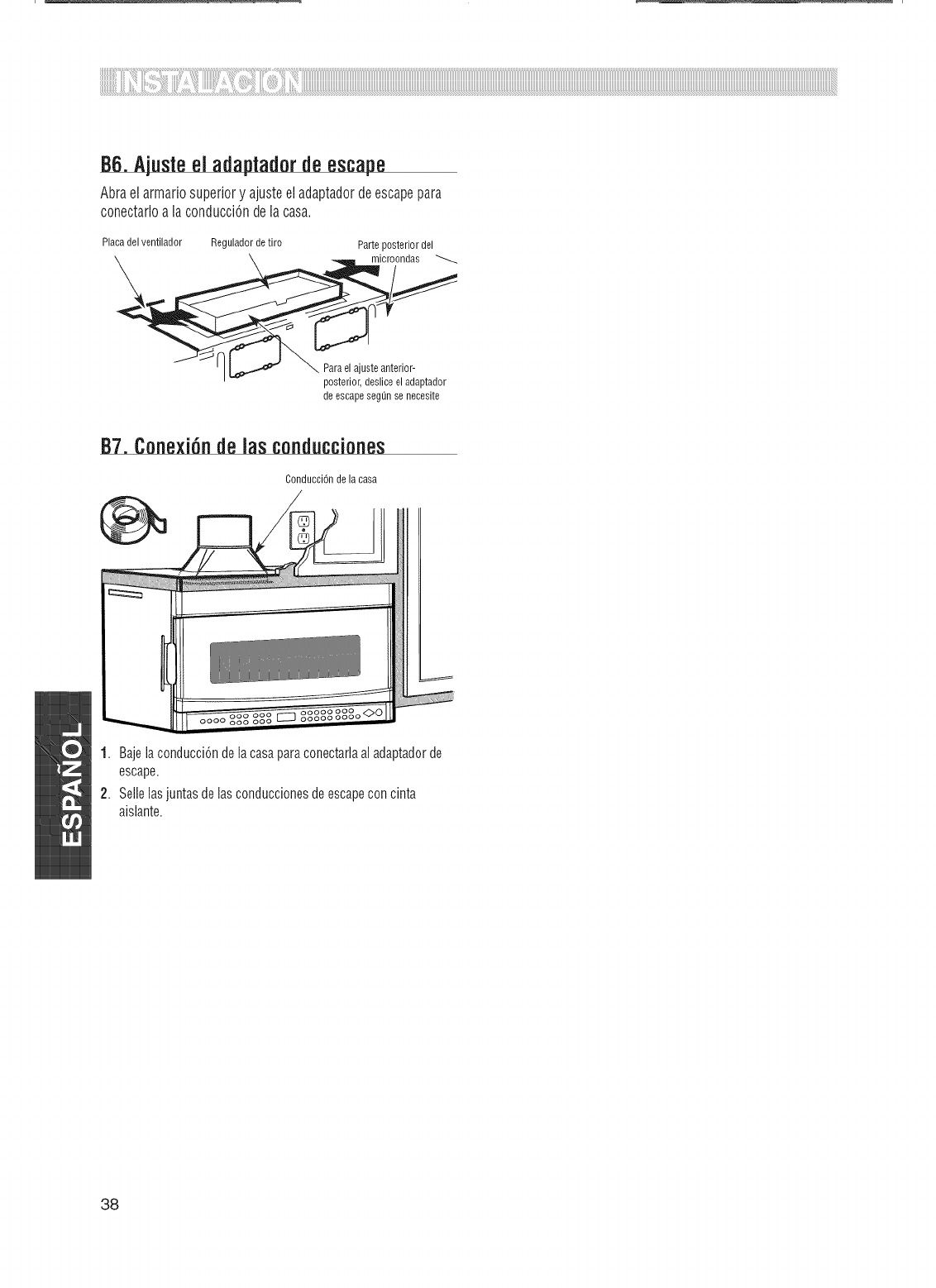
86. Ajusteel adaptadorde escape
Abraelarmariosuperiory ajusteeladaptadordeescapepara
conectarloalaconducciOndelacasa.
Placadel ventilador Reguladorde tiro Parte posteriordel
microondas
Parael ajusteanterior-
posterior,desliceel adaptador
de escapesegOnsenecesite
1. Bajelaconducci6ndelacasaparaconectarlaaladaptadorde
escape.
2. Sellelasjuntasdelasconduccionesde escapeconcinta
aislante.
38
C.ESCAPEPOSTERIORALEXTERIOR(CONDUCCiONHORIZONTAL)
VISIONGENERALDELAINSTALACION
C1. Preparelaparedposterior
C2. Acoplelaplacademontajea lapared
C3. Prepareelarmariosuperior
C4. Ajusteelventilador
C5. Monteelmicroondas
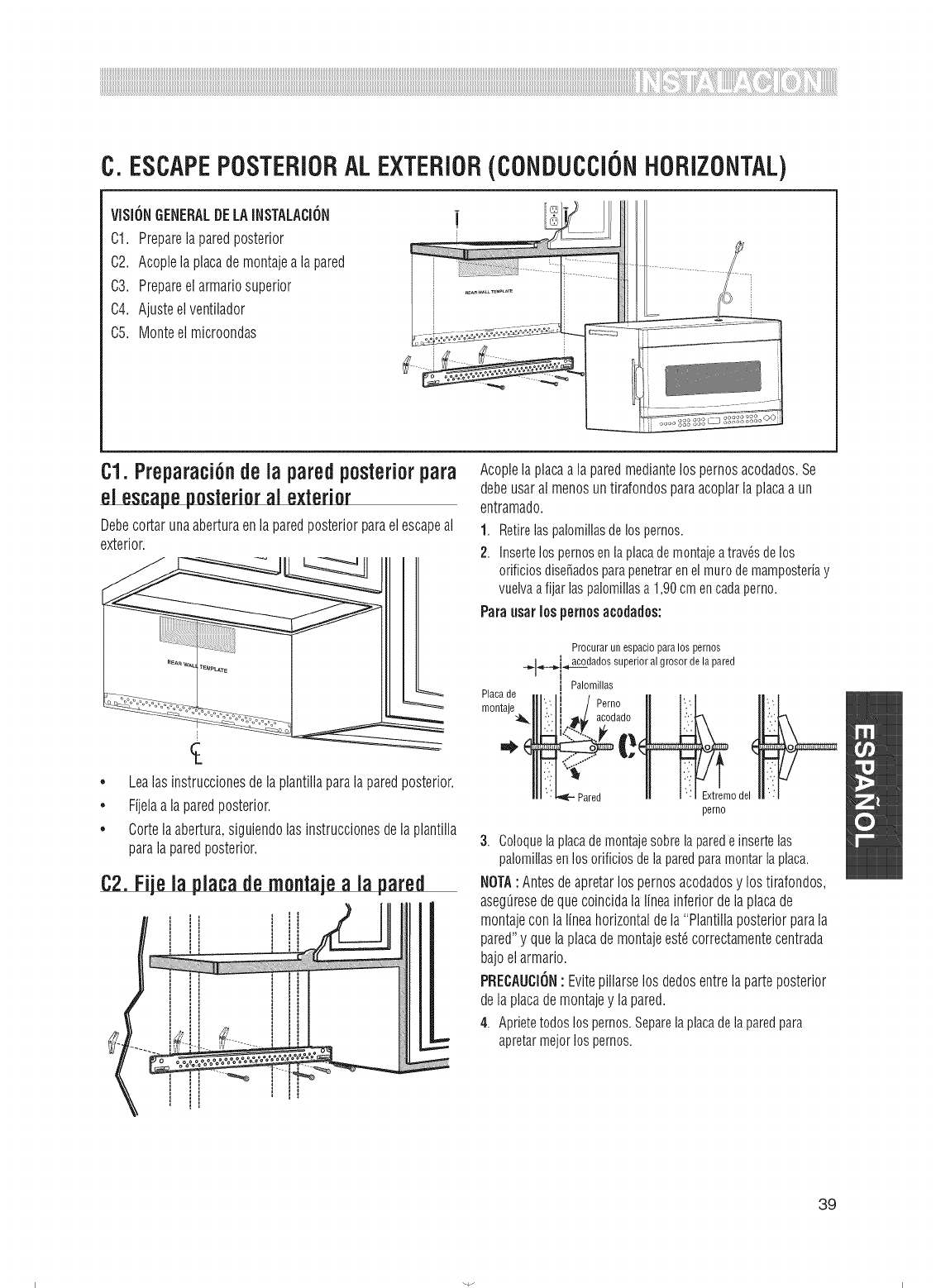
C1.Preparaci6nde la paredposteriorpara
el escapeposterior al exterior
Debecortarunaaberturaenlaparedposteriorparaelescapeal
exterior.
Lealasinstruccionesdelaplantillaparalaparedposterior.
Fijelaalaparedposterior.
Cortelaabertura,siguiendolasinstruccionesdelaplantilla
Acoplelaplacaa laparedmediantelospernosacodados.Se
debeusaral menosuntirafondosparaacoplarlaplacaa un
entramado.
1. Retirelaspalomillasdelospernos.
2. Insertelospernosenlaplacademontajeatrav_sdelos
orificiosdise_adosparapenetrarenelmurodemamposteriay
vuelvaafijarlaspalomillasa1,90cmencadaperno.
Paraosarlospernosacodados:
Proourarun espacioparalos pernos
_,_.,_,......._.ia_tcodadossuperioral grosor dela pared
i Palomillas
Placade . , .
montae "' i Perno ..', .:
II
odel
perno
3. Coloquelaplacademontajesobrelaparedeinsertelas
palomillasenlosorificiosdelaparedparamontarlaplaca.
NOTA:Antesdeapretarlospernosacodadosy lostirafondos,
aseg_resedequecoincidalalineainferiordelaplacade
montajeconlalineahorizontaldela"Plantillaposteriorparala
pared"y quelaplacademontajeest_correctamentecentrada
bajoelarmario.
PRECAUCION: Evitepillarselosdedosentrelaparteposterior
delaplacademontajey lapared.
4. Aprietetodoslospernos.Separelaplacadelaparedpara
apretarmejorlospernos.
39
I I
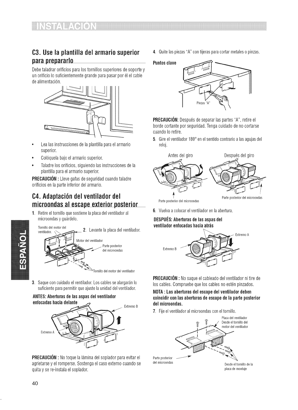
C3.Usela plantilladelarmariosuperior
paraprepararlo
Debetaladrarorificiosparalostornillossuperioresdesoportey
unorificioIosuficientementegrandeparapasarper61elcable
dealimentaci6n.
4. Quitelaspiezas"A"contijerasparacortarmetalesopinzas.
Punlosclave
Piezas"A"
• Lealasinstruccionesdelaplantillaparaelarmario
superior.
• Col6quelabajoelarmariosuperior.
• Taladrelosorificios,siguiendolasinstruccionesdela
plantillaparaelarmariosuperior.
PRECAUCION: Llevegafasdeseguridadcuandotaladre
orificiosenlaparteinferiordelarmario.
C4.Adaptaci6ndel ventiladordel
microondasal escapeexterior posterior
1. Retireeltornilloquesostienelaplacadelventiladoral
microondasy gu_rdelo.
Tomillodel motor del
ventilador. 2. Levantela placadelventilador.
Motordel ventilador
posterior
del microondas
motordel ventilador
3. Saqueconcuidadoelventilador.Loscablessealargar_nIo
suficienteparapermitir queajustela unidaddelventilador.
ANTES:Abertorasdelasaspasdelventilader
enfecadashaciadelante
i Extremo B
E×tremoA
PRECAUCION•NotoquelaI_.minadelsopladorparaevitarel
agrietarsey elromperse.Sostengaelcaseexternocuandose
quitay sere-instalaelsoplador.
PRECAUCION:Despu6sdesepararlaspartes"A",retireel
bordecortanteperseguridad.Tengacuidadodenocortarse
cuandoIo retire.
5. Gireelventilador1800enelsentidocontrarioalasagujasdel
reloj.
Antesdel ire Despu6sdelgiro
Parteposteriordelmicroondas
Parteposteriordel microondas
6. Vuelvaacolocarelventiladorenlaabertura.
DESPUES:Aberiurasdelasaspasdel
ventiladorenfecadashaciaatr_s
ExtremeB
PRECAUCiON: Nosaqueelcableadodelventiladornitire de
loscables.Compruebequeloscablesnoest_npinzados.
NOTA: Losaberturasdelescapedelventiladordeben
ceincidirconlosaberturasdeescapedela porteposterior
delmicreondas.
Parteposterior
del microondas
Fijeelventiladoralmicroondasconeltornillo.
Placadelventilador
_- _ D,:c_doer_leI°vr:,iItli_a_eelr
Desde el tomillo de la
placade montaje
4O
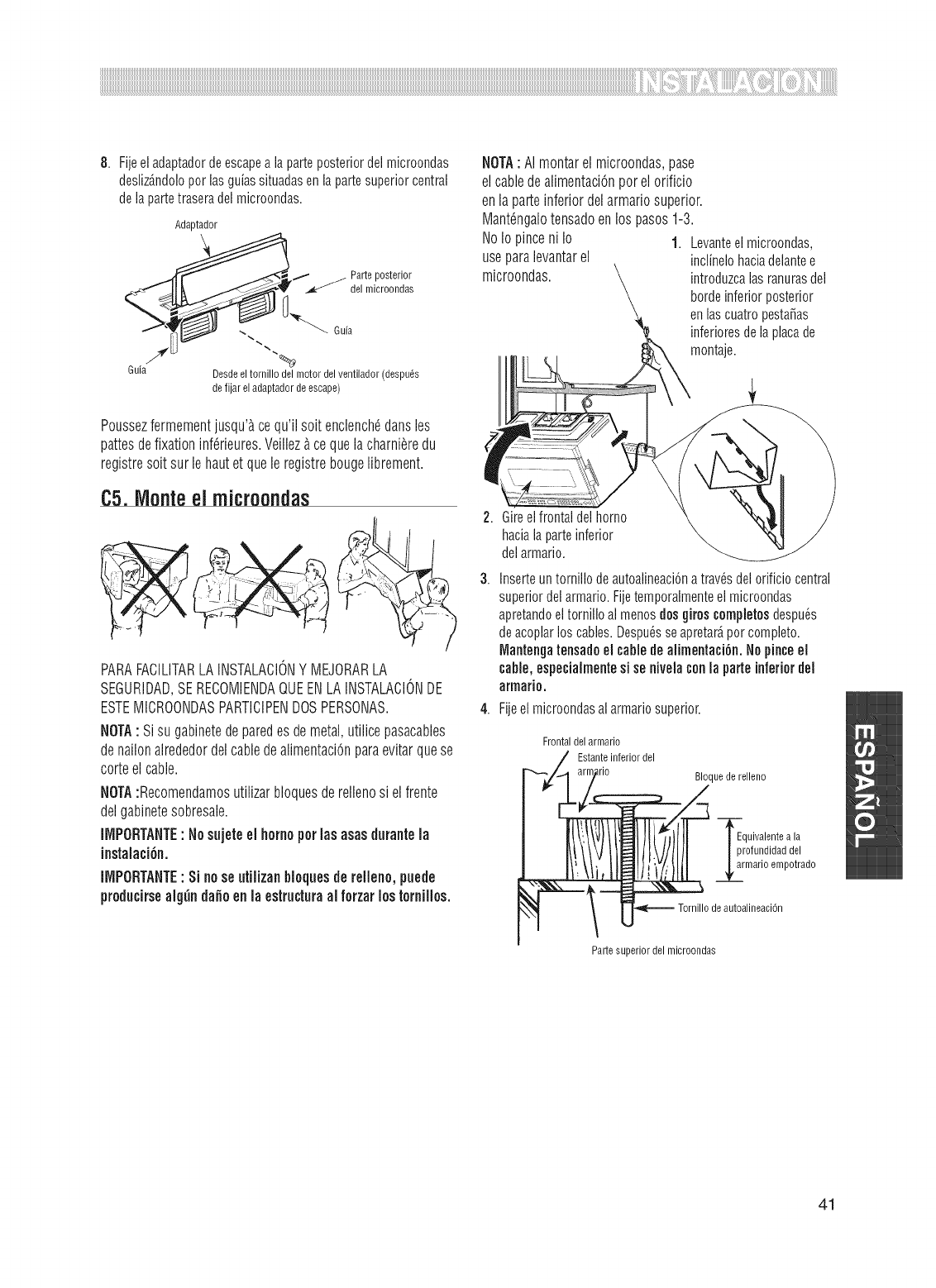
8. Fijeel adaptadorde escapea iaparteposteriordel microondas
desliz_ndoloperlasguiassituadasenlapartesuperiorcentral
de lapartetraseradel microondas.
Adaptador
I" j Parteposterior
del microondas
Guia Desdeeltomillo del motordel ventilador (despues
defijar eladaptadordeescape)
Poussezfermementjusqu'_,cequ'ilsoitenclench_dansles
pattesdefixationinf_rieures.Veillez_.cequelacharni_redu
registresoitsurlehautet quele registrebougelibrement.
C5.Monteel microondas
PARAFACILITARLAINSTALACIONY IV1EJORARLA
SEGURIDAD,SERECOMIENDAQUEENLAINSTALACIONDE
ESTEIVIICROONDASPARTICIPENDOSPERSONAS.
NOTA: Sisugabinetedeparedesdemetal,utilicepasacables
denailonalrededordelcabledealimentaci6nparaevitarquese
corteelcable.
NOTA:Recomendamosutilizarbloquesderellenosi elfrente
delgabinetesobresale.
_MPORTANTE:Nosujeteel homoperlasasasd_rantela
instalaci6n.
iiViPORTANTE: Sinoseutiiizanblequesderellene,puede
preducirsealg_nda_eenla estructuraal ferzarlostornilles.
NOTA: AI montar el microondas,pase
el cabledealimentaci6nper el orificio
en la parte inferior del armariosuperior.
IVlant_ngalotensadoen los pasos1-3.
NoIo pince ni Io 1. Levanteelmicroondas,
useparalevantarel inclinelohaciadelantee
microondas, introduzcalasranurasdel
bordeinferiorposterior
enlascuatropesta_as
inferioresdela placade
montaje.
Gireelfrontaldel homo
haciala parteinferior
del armario.
3. Inserteun tornillodeautoalineaci6natrav_sdelorificiocentral
superiordel armario.Fijetemporalmenteel microondas
apretandoel tornilloal menosdosgiros completesdespu_s
deacoplarloscables.Despu_sseapretar_per complete.
_antengatensadoel cabledealimentaci6n.Nopinceel
cable,especialmentesi senivelaconla parteinferiordel
armario.
4. Fijeel microondasai armariosuperior.
Frontaldelarmario
Estanteinferiordel
_rio Bloquede relleno
ErqUivalentea la
rofundidaddel
marie empotrado
deautoalineaci6n
Partesuperiordel microondas
41
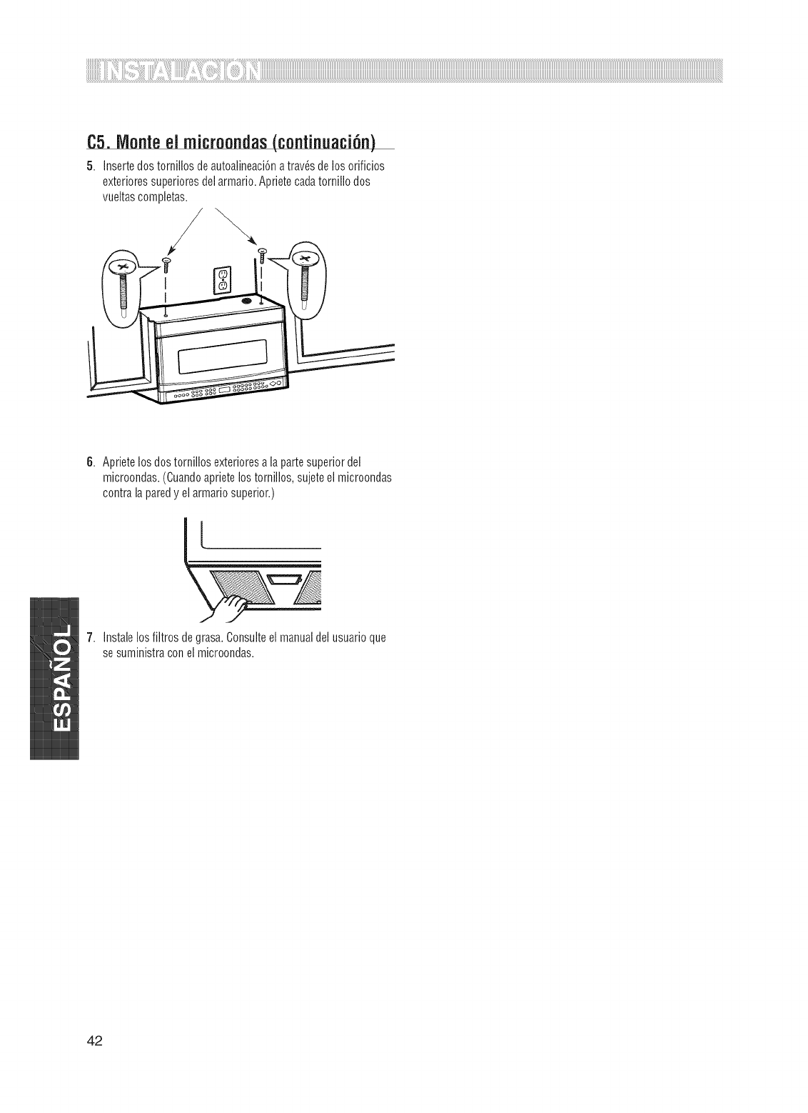
C5. Monte el microondas(continuaci6n)
5. Insertedos tomillosdeautoalineaci6na tray,s delosorificios
e×terioressuperioresdelarmario.Aprietecadatomillodos
vueltascompietas.
6. Aprietelos dostorniilos exterioresa lapartesuperiordel
microondas.(Cuandoaprietelostomillos,sujeteelmicroondas
contrala paredy el armariosuperior.)
7. Instalelosfiltros de grasa.Consulteel manualdel usuarioque
sesuministraconelmicroondas.
42
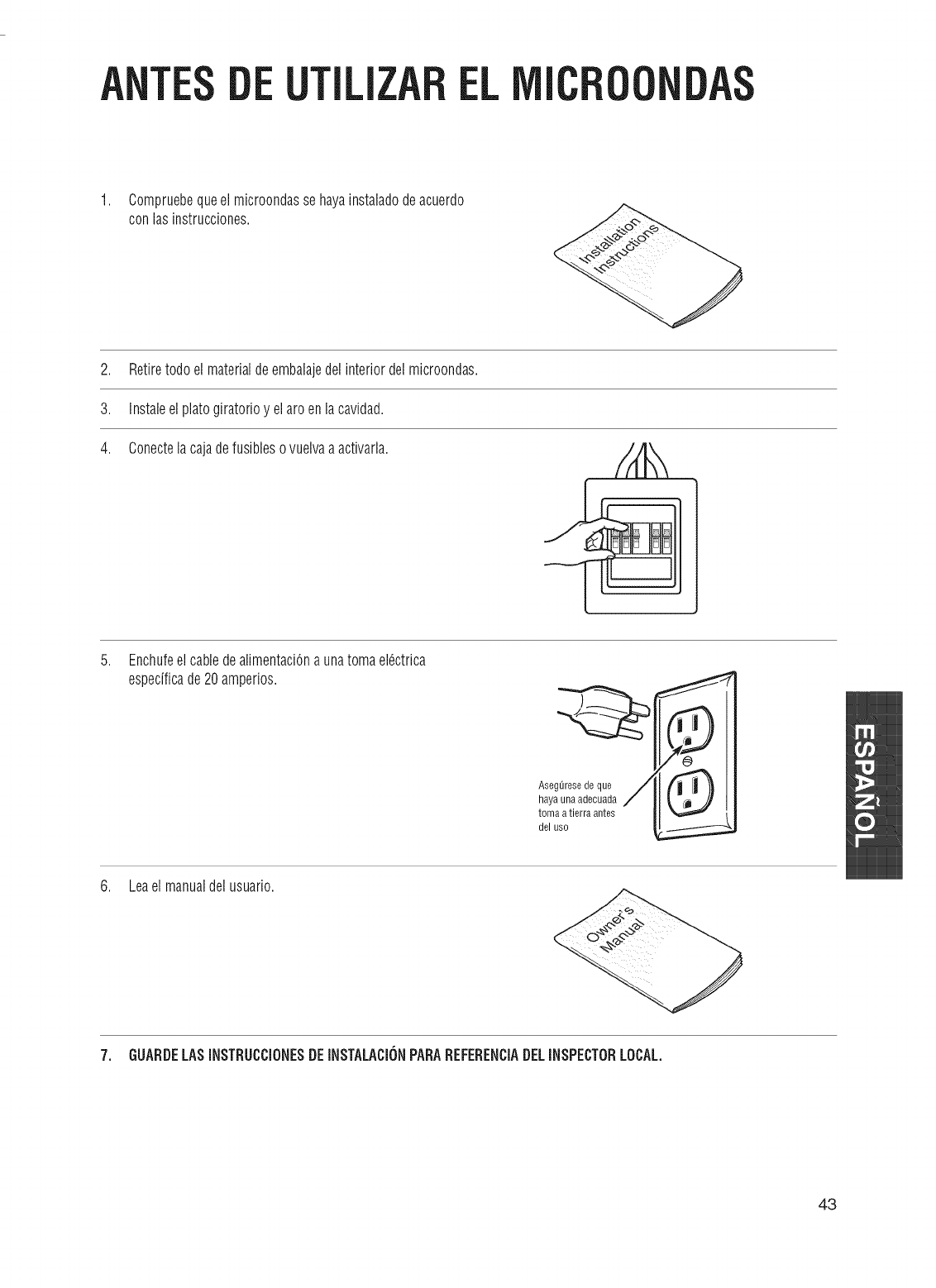
UTiLIZAREL IC
1. Compruebequeelmicroondassehayainstaladodeacuerdo
conlasinstrucciones.
2. Retiretodoelmaterialdeembalajedelinteriordelmicroondas.
3. Instaleelplatogiratorioy elaroenlacavidad.
4. Conectelacajadefusiblesovuelvaaactivarla.
,EnchufeelcabledealimentaciOna unatomael6ctrica
especificade20amperios.
AsegOresedeque
haya unaadecuada
tomaa tierraantes
del uso
6. Leaelmanualdelusuario.
7. GUARDELASiNSTRUCCiONESDEiNSTALACiONPARAREFERENCiADELiNSPECTORLOCAL.
43

EL I T E
Code No. (N.-°de c6digo) " DE68-O3654A-03
