Kenmore Elite 79097153510 User Manual ELECTRIC RANGE Manuals And Guides 1203289L
User Manual: Kenmore Elite 79097153510 79097153510 KENMORE ELITE ELECTRIC RANGE - Manuals and Guides View the owners manual for your KENMORE ELITE ELECTRIC RANGE #79097153510. Home:Kitchen Appliance Parts:Kenmore Elite Parts:Kenmore Elite ELECTRIC RANGE Manual
Open the PDF directly: View PDF ![]() .
.
Page Count: 20
United States INSTALLATION AND SERVICEMUST BEPERFORMED BY A QUALIFIED INSTALLER.
IMPORTANT: SAVE FOR LOCAL ELECTRICAL INSPECTOR'S USE.
READ AND SAVE THESE INSTRUCTIONS FOR FUTURE REFERENCE.
FOR YOUR SAFETY: Do not store or use gasoline or other
flammable vapors and liquids in the vicinity of this or any other appliance.
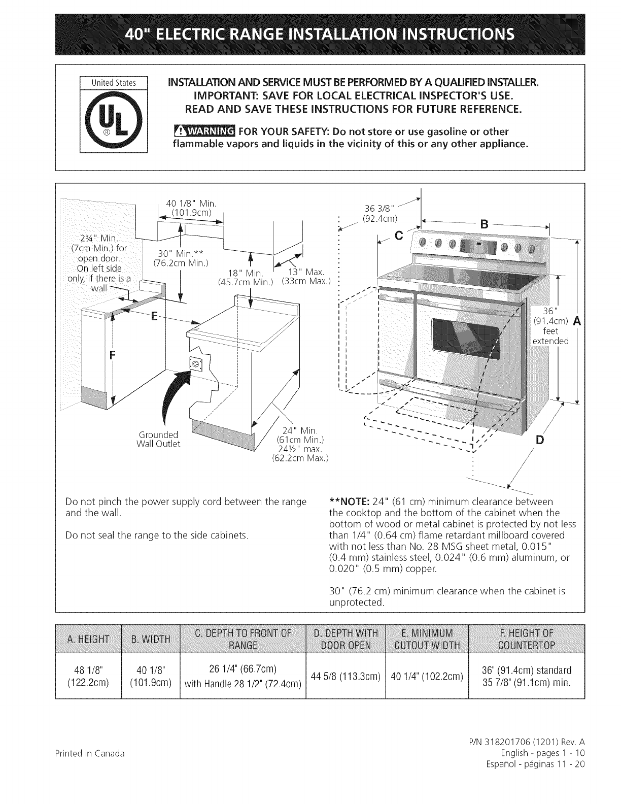
40 1/8" Min.
(101.9cm)
23A'' Min
(7cm Min.) for 30" Min.**
open door (76.2cm Min.)
On eft side /
on y, if there isa _|
cwal/ _3_ 18" Min. ' 13" Max.
(45.7cm Min.) (33cm Max.)
36"
(91.4cm) A
Grounded 24" Min.
Wall Outlet (61cm Min.)
241/2" max.
(62.2cm Max.)
D
Do not pinch the power supply cord between the range
and the wall.
Do not seal the range to the side cabinets.
**NOTE: 24" (61 cm) minimum clearance between
the cooktop and the bottom of the cabinet when the
bottom of wood or metal cabinet is protected by not less
than 1/4" (0.64 cm) flame retardant millboard covered
with not lessthan No. 28 MSG sheet metal, 0.01 5"
(0.4 ram) stainless steel, 0.024" (0.6 mm) aluminum, or
0.020" (0.5 mm) copper.
30" (76.2 cm) minimum clearance when the cabinet is
unprotected.
48 1/8"
(122.2cm)
40 1/8" 26 1/4"(66.7cm) 44 5/8 (113.3cm) 40 1/4" (102.2cm)
(101.9cm) with Handle28 1/2" (72.4cm)
36" (91.4cm) standard
35 7/8" (91.1cm) rain.
Printed in Canada
P/N 318201706 (1201) Rev.A
English - pages 1 - 10
Espa_ol - p_iginas 11 - 20
important Notes to the Installer
1. Read all instructions contained in these installation
instructions before installing range.
2. Remove all packing material from the oven
compartments before connecting the electrical supply
to the range (see "Preparation", page 6).
3. Two anti-tip brackets, located inside the oven cavity
MUST be installed (see "Anti-Tip Bracket Installation",
page 8).
4. Observe all governing codes and ordinances.
5. Be sure to leave these instructions with the consumer.
important Note to the Consumer
Keep these instructions with your owner's guide for future
reference.
IMPORTANT SAFETY
INSTRUCTION
• Be sure your range is installed and grounded
properly by a qualified installer or service
technician.
This range must be electrically grounded in
accordance with local codes or, in their absence,
with the National Electrical Code ANSI/NFPA No.
70--latest edition.
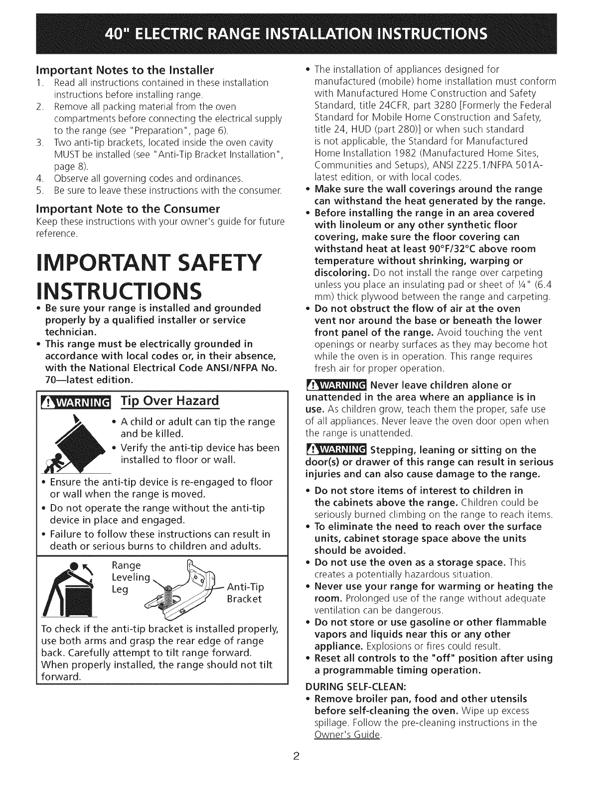
Tip Over Hazard
• Achild or adult can tip the range
and be killed.
• Verify the anti-tip device has been
installed to floor or wall.
Ensure the anti-tip device is re-engaged to floor
or wall when the range is moved.
Do not operate the range without the anti-tip
device in place and engaged.
Failure to follow these instructions can result in
death or serious burns to children and adults.
Range __T_
Leveling
Leg _ Anti-Tip
/__.__/" Bracket
To check if the antFtip bracket is installed properly,
use both arms and grasp the rear edge of range
back. Carefully attempt to tilt range forward.
When properly installed, the range should not tilt
forward.
The installation of appliances designed for
manufactured (mobile) home installation must conform
with Manufactured Home Construction and Safety
Standard, title 24CFR, part 3280 [Formerly the Federal
Standard for Mobile Home Construction and Safety,
title 24, HUD (part 280)] or when such standard
is not applicable, the Standard for Manufactured
Home Installation 1982 (Manufactured Home Sites,
Communities and Setups), ANSI Z225.1/NFPA 501A-
latest edition, or with local codes.
Make sure the wall coverings around the range
can withstand the heat generated by the range.
Before installing the range in an area covered
with linoleum or any other synthetic floor
covering, make sure the floor covering can
withstand heat at least 90°F/32°C above room
temperature without shrinking, warping or
discoloring. Do not install the range over carpeting
unless you place an insulating pad or sheet of 1/4"(6.4
mm) thick plywood between the range and carpeting.
Do not obstruct the flow of air at the oven
vent nor around the base or beneath the lower
front panel of the range. Avoid touching the vent
openings or nearby surfaces as they may become hot
while the oven is in operation. This range requires
fresh air for proper operation.
Never leave children alone or
unattended in the area where an appliance is in
use. As children grow, teach them the proper, safe use
of all appliances. Never leave the oven door open when
the range is unattended.
Stepping, leaning or sitting on the
door(s) or drawer of this range can result in serious
injuries and can also cause damage to the range.
Do not store items of interest to children in
the cabinets above the range. Children could be
seriously burned climbing on the range to reach items.
To eliminate the need to reach over the surface
units, cabinet storage space above the units
should be avoided.
Do not use the oven as a storage space. This
creates a potentially hazardous situation.
Never use your range for warming or heating the
room. Prolonged use of the range without adequate
ventilation can be dangerous.
Do not store or use gasoline or other flammable
vapors and liquids near this or any other
appliance. Explosions or fires could result.
Reset all controls to the "off" position after using
a programmable timing operation.
DURING SELF-CLEAN:
Remove broiler pan, food and other utensils
before self-cleaning the oven. Wipe up excess
spillage. Follow the pre-cleaning instructions in the
Owner's Guide.
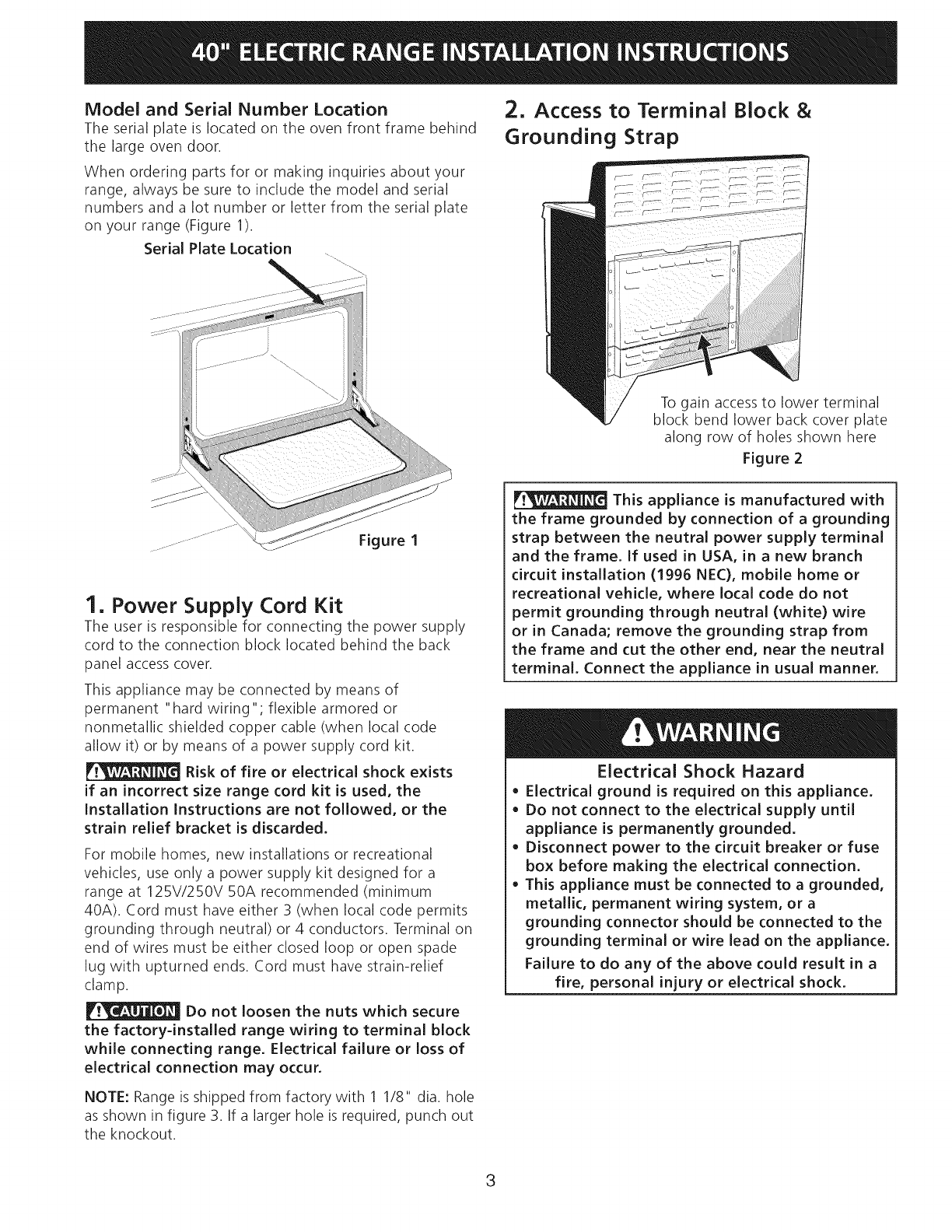
Model and Serial Number Location
The serial plate is located on the oven front frame behind
the large oven door.
When ordering parts for or making inquiries about your
range, always be sure to include the model and serial
numbers and a lot number or letter from the serial plate
on your range (Figure 1).
Serial Plate Location
To gain access to lower terminal
block bend lower back cover plate
along row of holes shown here
Figure 2
1. Power Supply Cord Kit
The user is responsible for connecting the power supply
cord to the connection block located behind the back
panel access cover.
This appliance may be connected by means of
permanent "hard wiring"; flexible armored or
nonmetallic shielded copper cable (when local code
allow it) or by means of a power supply cord kit.
Risk of fire or electrical shock exists
if an incorrect size range cord kit is used, the
Installation Instructions are not followed, or the
strain relief bracket is discarded.
For mobile homes, new installations or recreational
vehicles, use only a power supply kit designed for a
range at 125V/250V 50A recommended (minimum
40A). Cord must have either 3 (when local code permits
grounding through neutral) or 4 conductors. Terminal on
end of wires must be either closed loop or open spade
lug with upturned ends. Cord must have strain-relief
clamp.
Do not loosen the nuts which secure
the factory=installed range wiring to terminal block
while connecting range. Electrical failure or loss of
electrical connection may occur.
NOTE: Range is shipped from factory with 1 1/8" dia. hole
as shown in figure 3. If a larger hole is required, punch out
the knockout.
This appliance is manufactured with
the frame grounded by connection of a grounding
strap between the neutral power supply terminal
and the frame. If used in USA, in a new branch
circuit installation (1996 NEC), mobile home or
recreational vehicle, where local code do not
permit grounding through neutral (white) wire
or in Canada; remove the grounding strap from
the frame and cut the other end, near the neutral
terminal. Connect the appliance in usual manner.
Electrical Shock Hazard
• Electrical ground is required on this appliance.
• Do not connect to the electrical supply until
appliance is permanently grounded.
• Disconnect power to the circuit breaker or fuse
box before making the electrical connection.
• This appliance must be connected to a grounded,
metallic, permanent wiring system, or a
grounding connector should be connected to the
grounding terminal or wire lead on the appliance.
Failure to do any of the above could result in a
fire, personal injury or electrical shock.
3
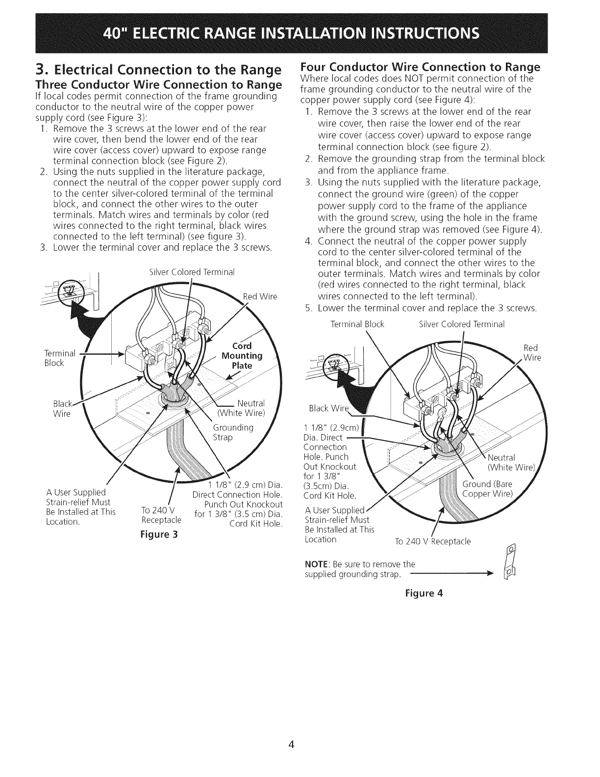
3. Electrical Connection to the Range
Three Conductor Wire Connection to Range
If local codes permit connection of the frame grounding
conductor to the neutral wire of the copper power
supply cord (see Figure 3):
1. Remove the 3 screws at the lower end of the rear
wire cover, then bend the lower end of the rear
wire cover (access cover) upward to expose range
terminal connection block (see Figure 2).
2. Using the nuts supplied in the literature package,
connect the neutral of the copper power supply cord
to the center silver-colored terminal of the terminal
block, and connect the other wires to the outer
terminals. Match wires and terminals by color (red
wires connected to the right terminal, black wires
connected to the left terminal) (see figure 3).
3. Lower the terminal cover and replace the 3 screws.
Silver Colored Terminal
Red Wire
Four Conductor Wire Connection to Range
Where local codes does NOT permit connection of the
frame grounding conductor to the neutral wire of the
copper power supply cord (see Figure 4):
1. Remove the 3 screws at the lower end of the rear
wire cover, then raise the lower end of the rear
wire cover (access cover) upward to expose range
terminal connection block (see figure 2).
2. Remove the grounding strap from the terminal block
and from the appliance frame.
3. Using the nuts supplied with the literature package,
connect the ground wire (green) of the copper
power supply cord to the frame of the appliance
with the ground screw, using the hole in the frame
where the ground strap was removed (see Figure 4).
4. Connect the neutral of the copper power supply
cord to the center silver-colored terminal of the
terminal block, and connect the other wires to the
outer terminals. Match wires and terminals by color
(red wires connected to the right terminal, black
wires connected to the left terminal).
5. Lower the terminal cover and replace the 3 screws.
Terminal Block Silver Colored Terminal
Terminal
Block
Red
W i re
Wire
A User Supplied
Strain-relief Must
Be Installed at This
Location.
To 240 V
Receptacle
Figure 3
1 1/8" (2.9 cm) Dia.
Direct Connection Hole.
Punch Out Knockout
for 1 3/8" (3.5 cm) Dia.
Cord Kit Hole.
BlackWire
1 1/8" (2.9cm) _/
Dia. Direct II
Connection
Hole.Punch
Out Knockout
for 1 3/8"
(3.5cm) Dia.
Cord Kit Hole.
A User Supl
Strain-relief Must
Be Installed at This
Location To 240 V Receptacle
NOTE: Be sure to remove the
supplied grounding strap.
Figure 4
4
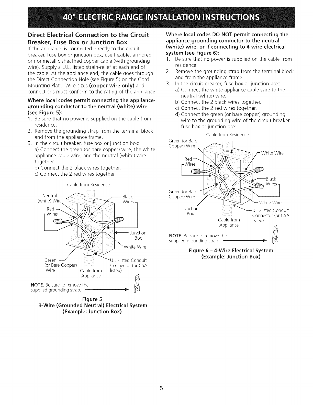
Direct Electrical Connection to the Circuit
Breaker, Fuse Box or Junction Box
If the appliance is connected directly to the circuit
breaker, fuse box or junction box, use flexible, armored
or nonmetallic sheathed copper cable (with grounding
wire). Supply a U.L. listed strain-relief at each end of
the cable. At the appliance end, the cable goes through
the Direct Connection Hole (see Figure 5) on the Cord
Mounting Plate. Wire sizes (copper wire only) and
connections must conform to the rating of the appliance.
Where local codes permit connecting the appliance-
grounding conductor to the neutral (white) wire
(see Figure 5):
1. Be sure that no power is supplied on the cable from
residence.
2. Remove the grounding strap from the terminal block
and from the appliance frame.
3. In the circuit breaker, fuse box or junction box:
a) Connect the green (or bare copper) wire, the white
appliance cable wire, and the neutral (white) wire
together.
b) Connect the 2 black wires together.
c) Connect the 2 red wires together.
Cable from Residence
(W_Ji_!_/_ i__re_ _ X_/_rCeksm
Green U L-listed Conduit
(or BareCopper) : .... Connector (or CSA
Wire Cablefrom listed)
Appliance
NOTE: Be sure to remove the
supplied grounding strap.
Figure 5
3-Wire (Grounded Neutral) Electrical System
(Example: Junction Box)
Where local codes DO NOT permit connecting the
appliance-grounding conductor to the neutral
(white) wire, or if connecting to 4-wire electrical
system (see Figure 6):
1. Be sure that no power is supplied on the cable from
residence.
2. Remove the grounding strap from the terminal block
and from the appliance frame.
3. In the circuit breaker, fuse box or junction box:
a) Connect the white appliance cable wire to the
neutral (white) wire.
b) Connect the 2 black wires together.
c) Connect the 2 red wires together.
d) Connect the green (or bare copper) grounding
wire to the grounding wire of the circuit breaker,
fuse box or junction box.
Cablefrom Residence
Green(or Bare
Copper)Wire ,
White Wire
Red
J_...(( Wires]
Green (or Bare /It _ _L" _ _I'_ /
Copper)Wire _!_ _ \
_ White Wire
Junction ..... _U.L.-listed Conduit
BOX Connector (or CSA
Cablefrom listed)
Appliance
NOTE: Besureto removethe
supplied grounding strap.
Figure 6 - 4-Wire Electrical System
(Example: Junction Box)
5
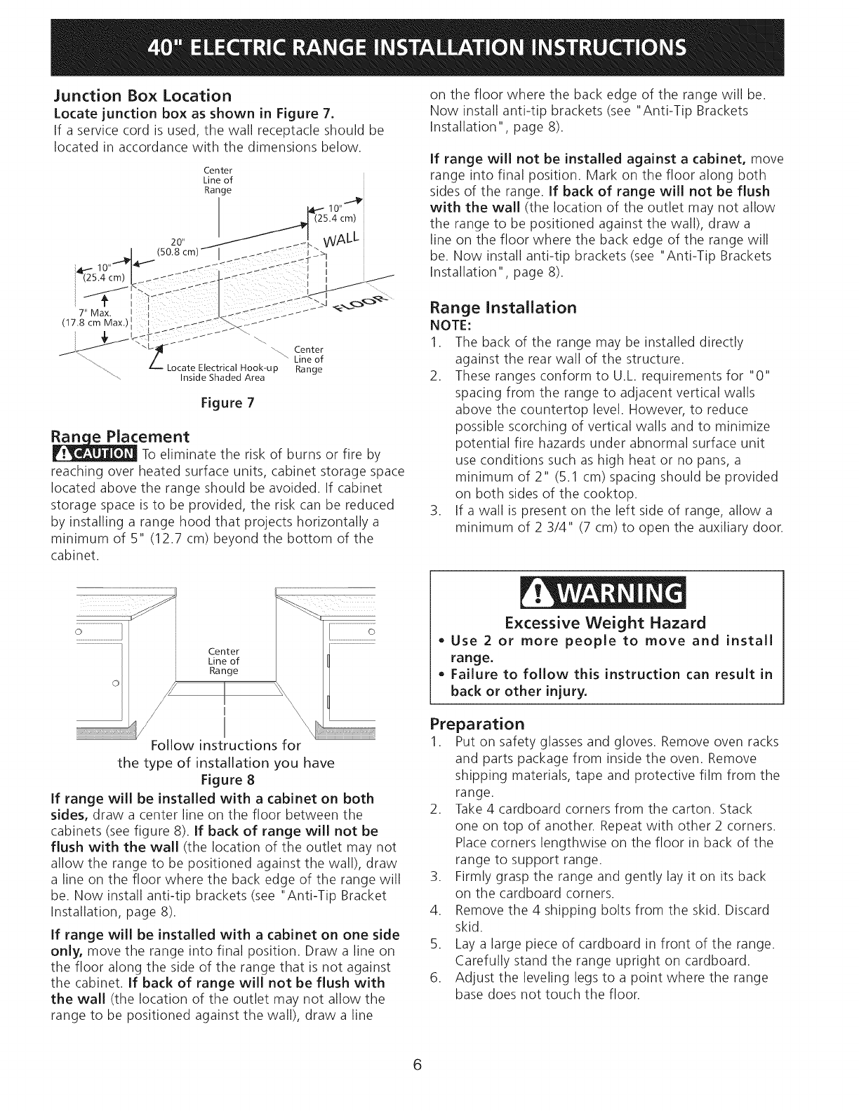
Junction Box Location
Locate junction box as shown in Figure 7.
If a service cord is used, the wall receptacle should be
located in accordance with the dimensions below.
Figure 7
ernent
To eliminate the risk of burns or fire by
reaching over heated surface units, cabinet storage space
located above the range should be avoided. If cabinet
storage space is to be provided, the risk can be reduced
by installing a range hood that projects horizontally a
minimum of 5" (12.7 cm) beyond the bottom of the
cabinet.
on the floor where the back edge of the range will be.
Now install anti-tip brackets (see "Anti-Tip Brackets
Installation" page 8).
If range will not be installed against a cabinet, move
range into final position. Mark on the floor along both
sides of the range. If back of range will not be flush
with the wall (the location of the outlet may not allow
the range to be positioned against the wall), draw a
line on the floor where the back edge of the range will
be. Now install anti-tip brackets (see "Anti-Tip Brackets
Installation", page 8).
Range Installation
NOTE:
1. The back of the range may be installed directly
against the rear wall of the structure.
2. These ranges conform to U.L. requirements for "0"
spacing from the range to adjacent vertical walls
above the countertop level. However, to reduce
possible scorching of vertical walls and to minimize
potential fire hazards under abnormal surface unit
use conditions such as high heat or no pans, a
minimum of 2" (5.1 cm) spacing should be provided
on both sides of the cooktop.
3. If a wall is present on the left side of range, allow a
minimum of 2 3/4" (7 cm) to open the auxiliary door.
Center
Line of
Range
/I
Follow instructions for
the type of installation you have
Figure 8
If range will be installed with a cabinet on both
sides, draw a center line on the floor between the
cabinets (see figure 8). If back of range will not be
flush with the wall (the location of the outlet may not
allow the range to be positioned against the wall), draw
a line on the floor where the back edge of the range will
be. Now install anti-tip brackets (see "Anti-Tip Bracket
Installation, page 8).
If range will be installed with a cabinet on one side
only, move the range into final position. Draw a line on
the floor along the side of the range that is not against
the cabinet. If back of range will not be flush with
the wall (the location of the outlet may not allow the
range to be positioned against the wall), draw a line
Excessive Weight Hazard
• Use 2 or more people to move and install
range.
• Failure to follow this instruction can result in
back or other injury.
Preparation
1. Put on safety glasses and gloves. Remove oven racks
and parts package from inside the oven. Remove
shipping materials, tape and protective film from the
range.
2. Take 4 cardboard corners from the carton. Stack
one on top of another. Repeat with other 2 corners.
Place corners lengthwise on the floor in back of the
range to support range.
3. Firmly grasp the range and gently lay it on its back
on the cardboard corners.
4. Remove the 4 shipping bolts from the skid. Discard
skid.
5. Lay a large piece of cardboard in front of the range.
Carefully stand the range upright on cardboard.
6. Adjust the leveling legs to a point where the range
base does not touch the floor.
6
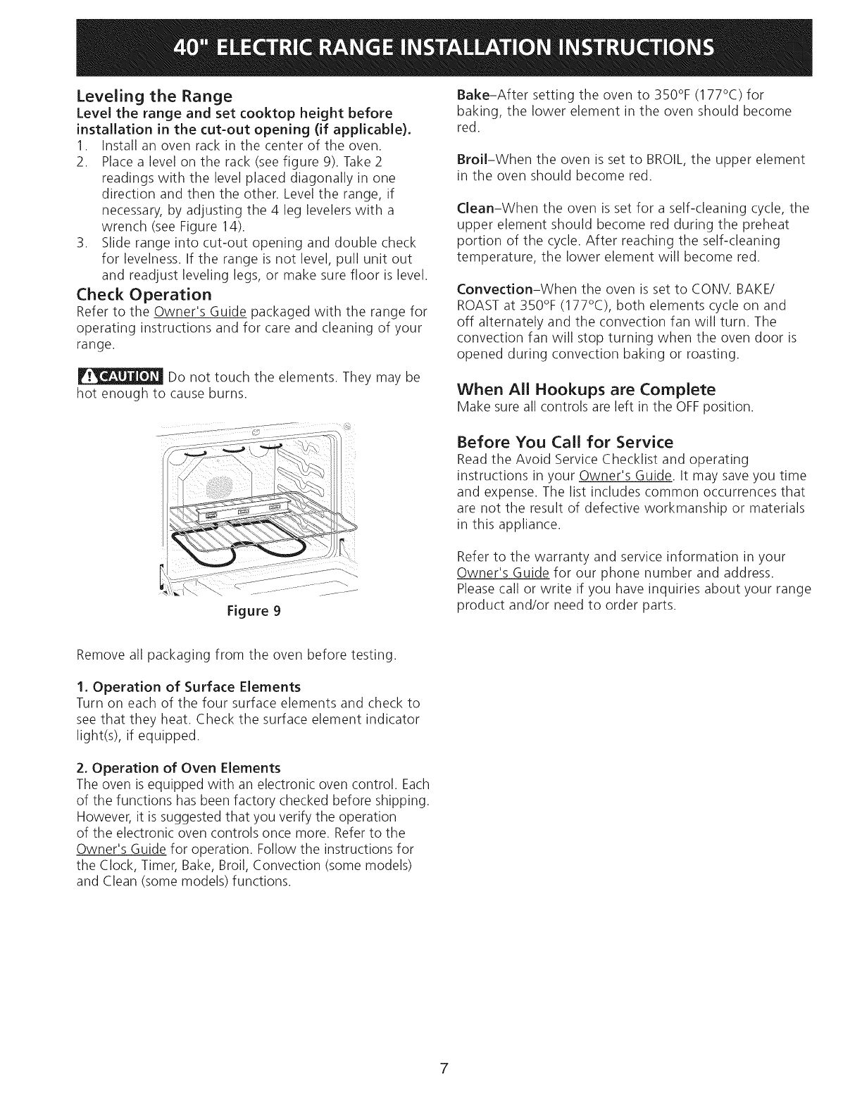
Leveling the Range
Level the range and set cooktop height before
installation in the cut=out opening (if applicable).
1. Install an oven rack in the center of the oven.
2. Place a level on the rack (see figure 9). Take 2
readings with the level placed diagonally in one
direction and then the other. Level the range, if
necessary, by adjusting the 4 leg levelers with a
wrench (see Figure 14).
3. Slide range into cut-out opening and double check
for levelness. If the range is not level, pull unit out
and readjust leveling legs, or make sure floor is level.
Check Operation
Refer to the Owner's Guide packaged with the range for
operating instructions and for care and cleaning of your
range.
Do not touch the elements. They may be
hot enough to cause burns.
Bake-After setting the oven to 350°F (177°C) for
baking, the lower element in the oven should become
red.
Broil-When the oven is set to BROIL, the upper element
in the oven should become red.
Clean-When the oven is set for a self-cleaning cycle, the
upper element should become red during the preheat
portion of the cycle. After reaching the self-cleaning
temperature, the lower element will become red.
Convection-When the oven is set to CONV. BAKE/
ROAST at 350% (177°C), both elements cycle on and
off alternately and the convection fan will turn. The
convection fan will stop turning when the oven door is
opened during convection baking or roasting.
When All Hookups are Complete
Make sure all controls are left in the OFFposition.
Before You Call for Service
Read the Avoid Service Checklist and operating
instructions in your Owner's Guide. It may save you time
and expense. The list includes common occurrences that
are not the result of defective workmanship or materials
in this appliance.
Figure 9
Refer to the warranty and service information in your
Owner's Guide for our phone number and address.
Please call or write if you have inquiries about your range
product and/or need to order parts.
Remove all packaging from the oven before testing.
1. Operation of Surface Elements
Turn on each of the four surface elements and check to
see that they heat. Check the surface element indicator
light(s), if equipped.
2. Operation of Oven Elements
The oven is equipped with an electronic oven control. Each
of the functions has been factory checked before shipping.
However, it is suggested that you verify the operation
of the electronic oven controls once more. Refer to the
Owner's Guide for operation. Follow the instructions for
the Clock, Timer, Bake, Broil, Convection (some models)
and Clean (some models) functions.
7
Anti-tip Bracket Installation
instructions
Important Safety Warning
To reduce the risk of tipping of the range, the range must
be secured to the floor by the properly installed anti-tip
bracket and screws packed with the range. Failure to
install the anti-tip bracket will allow the range to tip over
if excessive weight is placed on an open door or if child
climbs upon it. Serious injury might result from spilled hot
liquids or from the range itself.
If range is ever moved to a different location, the anti-tip
brackets must also be moved and installed with the range.
Instructions are provided for installation in wood or
cement floor. When fastening to floor, be sure that screws
do not penetrate electrical wiring or plumbing.
Tip Over Hazard
• Achild or adult can tip the range
and be killed.
• Verify the anti-tip device has been
installed to floor or wall.
• Ensure the anti-tip device is re-engaged to floor
or wall when the range is moved.
Do not operate the range without the anti-tip
device in place and engaged.
Failure to follow these instructions can result in
death or serious burns to children and adults.
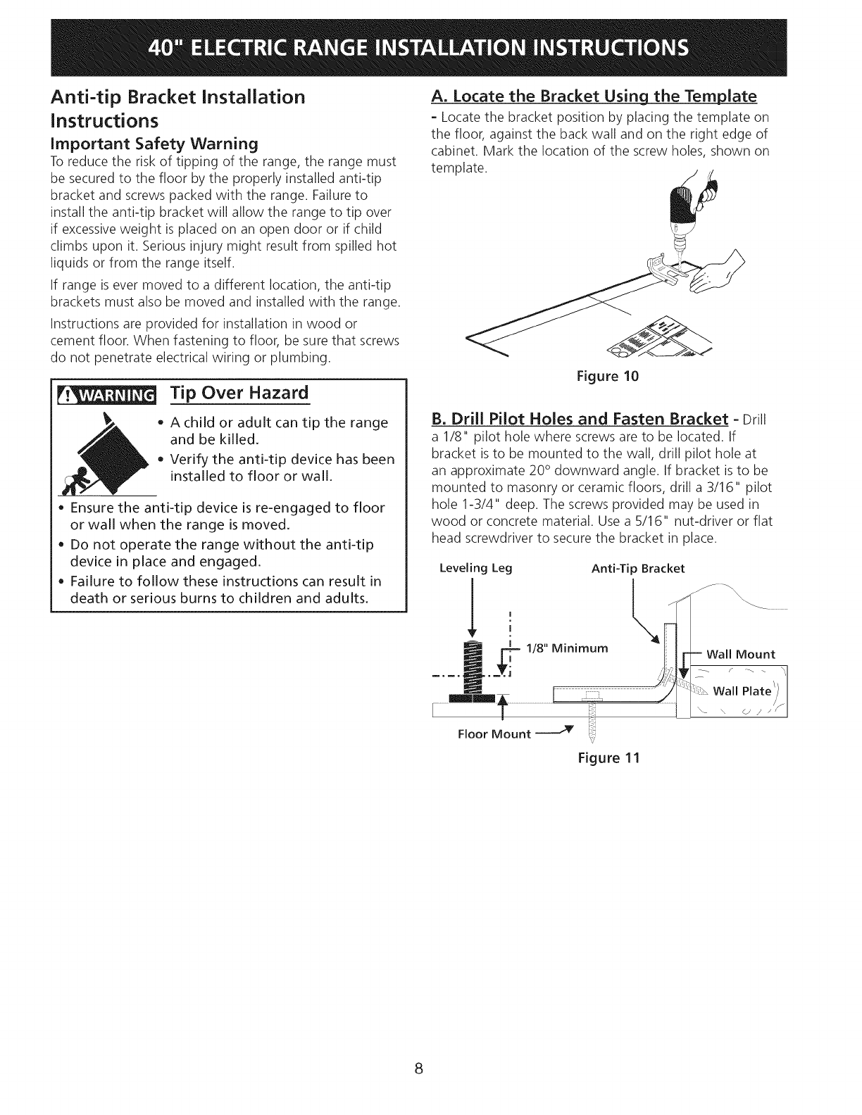
A. Locate the Bracket Using the Template
- Locate the bracket position by placing the template on
the floor, against the back wall and on the right edge of
cabinet. Mark the location of the screw holes, shown on
template.
Figure 10
B. Drill Pilot Holes and Fasten Bracket -Drill
a 1/8" pilot hole where screws are to be located. If
bracket is to be mounted to the wall, drill pilot hole at
an approximate 20° downward angle. If bracket is to be
mounted to masonry or ceramic floors, drill a 3/16" pilot
hole 1-3/4" deep. The screws provided may be used in
wood or concrete material. Use a 5/16" nut-driver or flat
head screwdriver to secure the bracket in place.
Leveling Leg Anti-Tip Bracket
........................................... Wall Plat:
Floor Mount _ ":_;
v
Figure 11
8
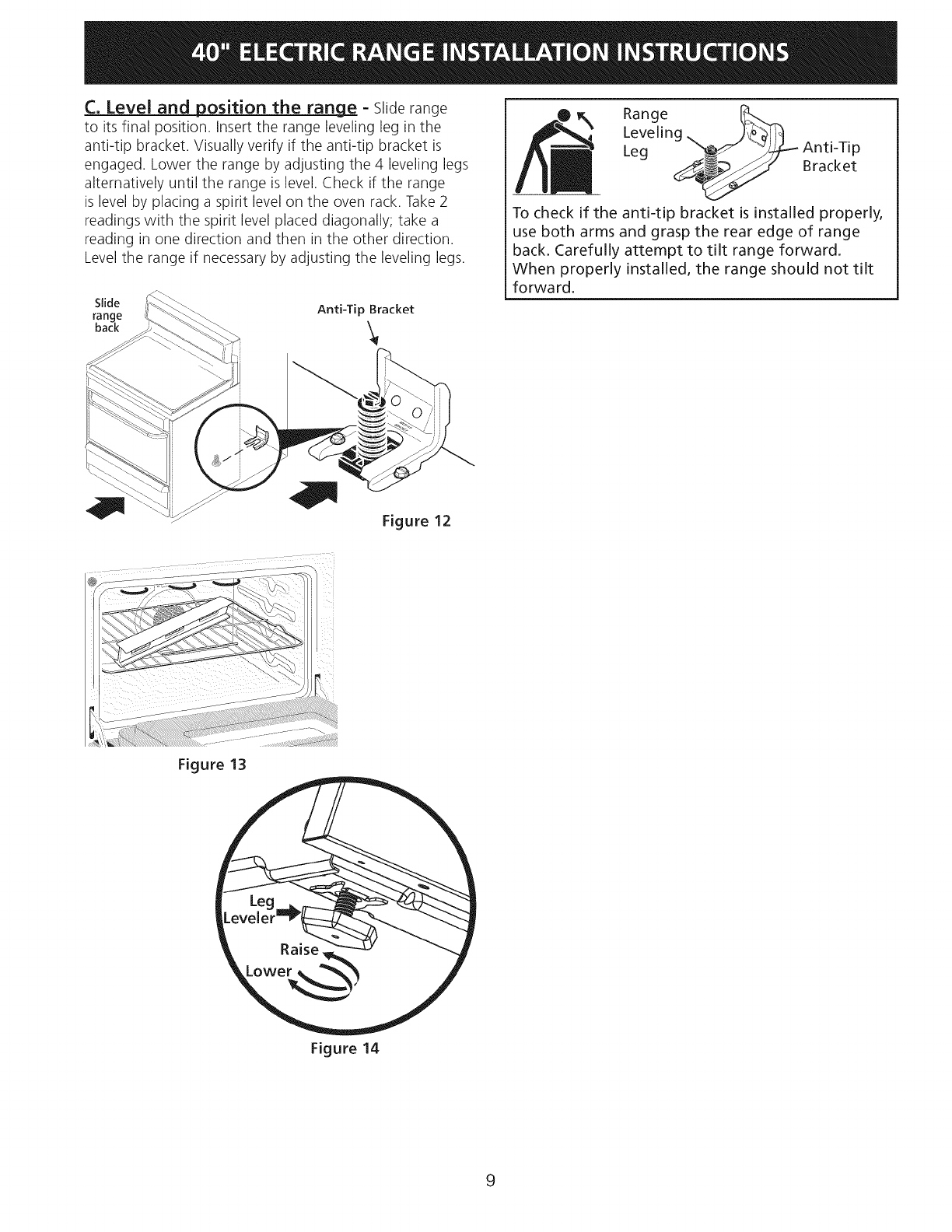
C. Level and position the rang_e_ - Slide range
to its final position. Insert the range leveling leg in the
anti-tip bracket. Visually verify if the anti-tip bracket is
engaged. Lower the range by adjusting the 4 leveling legs
alternatively until the range is level. Check if the range
is level by placing a spirit level on the oven rack. Take 2
readings with the spirit level placed diagonally; take a
reading in one direction and then in the other direction.
Level the range if necessary by adjusting the leveling legs.
Slide Anti-Tip Bracket
range
back
Range _.._
Leveling
Leg "_ Anti-Tip
__ Bracket
To check if the anti-tip bracket is installed properly,
use both arms and grasp the rear edge of range
back. Carefully attempt to tilt range forward.
When properly installed, the range should not tilt
forward.
Figure 12
Figure 13
Figure 14
9
10
Estados Unidos
LA INSTALACION Y EL SERVICIO DEBEN SER EFECTUADOS POR UN
INSTALADOR CAUFICADO.
IMPORTANTE: GUARDE ESTAS INSTRUCCIONES PARA USO DEL INSPECTOR
LOCAL DE ELECTRICIDAD. LEA Y GUARDE ESTAS INSTRUCCIONES PARA
REFERENCIA FUTURA.
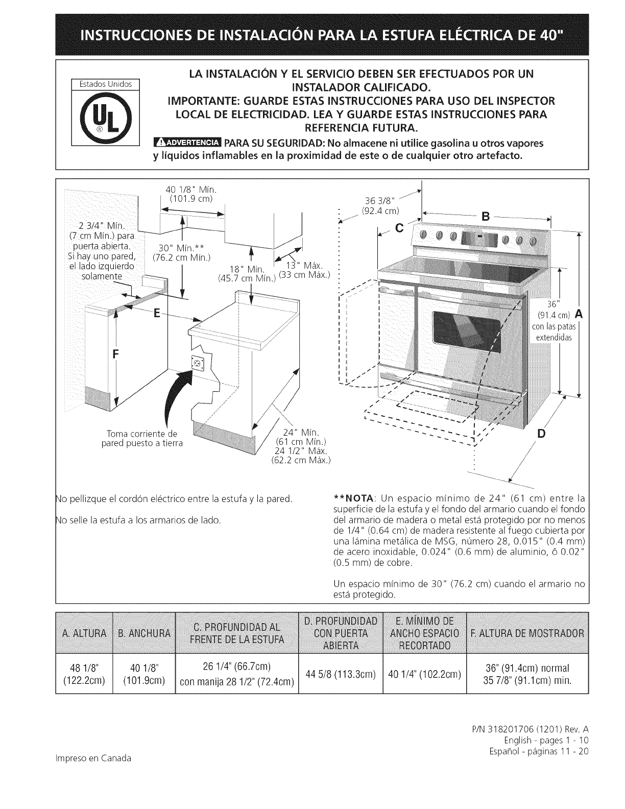
PARA SU SEGURIDAD: No almacene ni utilice gasolina u otros vapores
y liquidos inflamables en la proximidad de este o de cualquier otto artefacto.
2 3/4' Mfn
(7 cm Mfn. para
puerta abierta
Si hay uno pared,
el lado izquierdo
solamente
F
363/8"
(92.4 cm) ,I_ ............ B .............. _1
I
(91.4 cm) A
Toma corriente de
pared puesto a tierra
qo pellizque el cordOn electrico entre la estufa y la pared.
qo selle la estufa a los armarios de lado.
D
**NOTA: Un espacio m[nimo de 24" (61 cm) entre la
superficie de la estufa y el fondo del armario cuando el fondo
del armario de madera o metal est,1 protegido pot no menos
de 1/4" (0.64 cm) de madera resistente al fuego cubierta por
una I_imina met_ilica de MSG, nOmero 28, 0.015" (0.4 mm)
de acero inoxidable, 0.024" (0.6 mm) de aluminio, 6 0.02"
(0.5 mm) de cobre.
Un espacio m[nimo de 30" (76.2 cm) cuando el armario no
est,1 protegido.
48 1/8"
(122.2cm)
40 1/8" 26 1/4" (66.7cm) 44 5/8 (113.3cm) 40 1/4" (102.2cm)
(101.9cm) con manija 28 1/2" (72.4cm)
36" (91.4cm) normal
35 7/8" (91.1cm) rain.
Impreso en Canada
P/N 318201706 (1201) Rev.A
English - pages 1 - 10
Espaflol - p_iginas 11 - 20
Notas importantes para el Instalador
1. Lea todas las instrucciones contenidas en este manual
antes de instalar la estufa.
2. Saque todo el material usado en el embalaje del
compartimiento del homo antes de conectar el suministro
electrico a la estufa.
3. Dos soportes antivuelco DEBEN set instalados. Para
detalles, vea instrucciones en la paginas 18.
4. Observe todos los codigos y reglamentos pertinentes.
5. Deje estas instrucciones con el comprador.
Nota Importante para el Consumidor
Conserve estas instrucciones y el Manual del Usuario para
referencia futura.
IMPORTANTES
INSTRUCCIONE DE
SEGURIDAD
• Asegurese de que la estufa sea instalada y
conectada a tierra en forma apropiada pot un
instalador calificado o pot un tecnko.
• Esta estufa debe set electricamente puesta a tierra
de acuerdo con los c6digos locales, o en su ausencia,
con el Codigo Electrico Nacional ANSI/NFPA No. 70,
ultima edici6n.
• La instalacion de aparatos disehados para instalacion
en casas prefabricadas (moviles) debe conformar con el
Manufactured Home Construction and Safety Standard,
t[tulo 24CFR, parte 3280 [Anteriormente el Federal
Standard for Mobil Home Construction and Safety, t[tulo
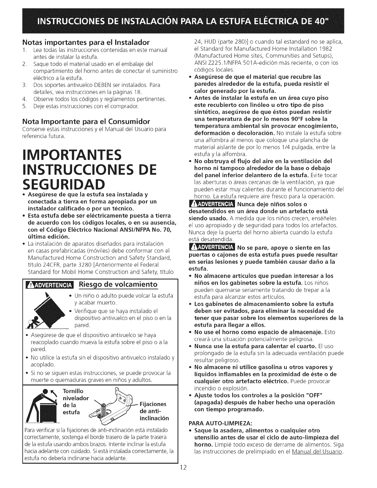
_r_ Riesgo de voicarniento
_ • Un niho o adulto puede volcar la estufa
y acabar muerto.
Verifique que se haya instalado el
dispositivo antivuelco en el piso o en la
pared.
Aseg0rese de que el dispositivo antivuelco se haya
reacoplado cuando mueva la estufa sobre el piso o a la
pared.
No utilice la estufa sin el dispositivo antivuelco instalado y
acoplado.
Si no se siguen estas instrucciones, se puede provocar la
muerte o quemaduras graves en nihos y adultos.
Tornillo _..._.
nivelador _ JJo'bJI_
de la _" _7L_ Fijaciones
estufa .__ de anti-
inclinaci6n
Para verificar si la fijaciones de anti-inclinacion est,1instalado
correctamente, sostenga el borde trasero de la parte trasera
de la estufa usando ambos brazos. Intente inclinar la estufa
hacia adelante con cuidado. Si est,1 instalada correctamente, la
estufa no deber[a inclinarse hacia adelante.
24, HUD (parte 280)] o cuando tal estandard no se aplica,
el Standard for Manufactured Home Installation 1982
(Manufactured Home sites, Communities and Setups),
ANSI Z225.1/NFPA 501A-edicion m_is reciente, o con los
codigos locales.
= Asegurese de que el material que recubre las
paredes alrededor de la estufa, pueda resistir el
calor generado pot la estufa,
• Antes de instalar la estufa en un _rea cuyo piso
este recubierto con lin61eo u otto tipo de piso
sintetico, asegurese de que estos puedan resistir
una temperatura de pot Io menos 90°F sobre la
temperatura ambiental sin provocar encogimiento,
deformaci6n o decoloraci6n. No instale la estufa sobre
una alfombra al menos que coloque una plancha de
material aislante de pot Io menos 1/4 pulgada, entre la
estufa y la alfombra.
• No obstruya el flujo del aire en la ventilaci6n del
homo ni tampoco alrededor de la base o debajo
del panel inferior delantero de la estufa. Evite tocar
las aberturas o _ireas cercanas de la ventilacion, ya que
pueden estar muy calientes durante el funcionamiento del
homo. La estufa requiere aire fresco para la operacion.
Nunca deje ni_os solos o
desatendidos en un _rea donde un artefacto est_
siendo usado. A medida que los nihos crecen, enseheles
el uso apropiado y de seguridad para todos los artefactos.
Nunca deje la puerta del homo abierta cuando la estufa
est,1 desatendida.
No se pare, apoye o siente en las
puertas o cajones de esta estufa pues puede resultar
en serias lesiones y puede tambien causar daffo a la
estufa.
= No almacene articulos que puedan interesar a los
niffos en los gabinetes sobre la estufa. Los nihos
pueden quemarse seriamente tratando de trepar a la
estufa para alcanzar estos art[culos.
• Los gabinetes de almacenamiento sobre la estufa
deben set evitados, para eliminar la necesidad de
tenet que pasar sobre los elementos superiores de la
estufa para Ilegar a ellos.
= No use el homo como espacio de almacenaje. Esto
create1 una situacion potencialmente peligrosa.
• Nunca use la estufa para calentar el cuarto. El uso
prolongado de la estufa sin la adecuada ventilacion puede
resultar peligroso.
= No almacene ni utilice gasolina u otros vapores y
liquidos inflamables en la proximidad de este o de
cualquier otto artefacto electrico. Puede provocar
incendio o explosion.
Ajuste todos los controles a la posicion "OFF"
(apagada) despues de haber hecho una operaci6n
con tiempo programado.
PARA AUTO-LIMPIEZA:
= Saque la asadera, alimentos o cualquier otto
utensilio antes de usar el ciclo de auto-limpieza del
homo. Limpie todo exceso de derrame de alimentos. Siga
las instrucciones de prelimpiado en el Manual del Usuario.
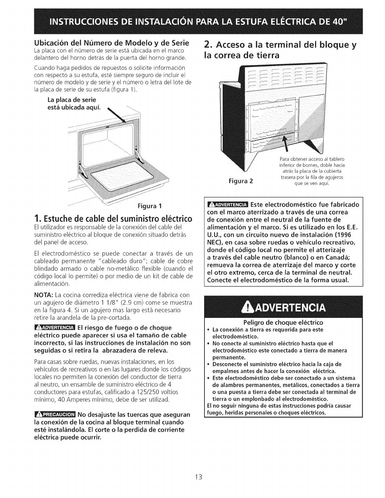
Ubicacion del Numero de Modelo y de Serie
La placa con el n0mero de serie est,1ubicada en el marco
delantero del homo detr_is de la puerta del homo grande.
Cuando haga pedidos de repuestos o solicite informacion
con respecto a su estufa, este siempre seguro de incluir el
n0mero de modelo y de serie y el n0mero o letra del Iote de
la placa de serie de su estufa (figura 1).
La placa de serie
est_ ubicada aqui. _ .......
It} ..........._,
......... "\ I
.....\
Figura I
1. Estuche de cable del suministro electrico
El utilizador es responsable de la conexiOn del cable del
suministro el@ctricoal bloque de conexi6n situado detr_is
del panel de acceso.
El electrodom@stico se puede conectar a trav@s de un
cableado permanente "cableado duro"; cable de cobre
blindado armado o cable no-met_ilico flexible (cuando el
c6digo local Io permite) o pot medio de un kit de cable de
alimentaci6n.
2. Acceso a la terminal dei bloque y
la correa de tierra
Figura 2
Para obtener acceso al tablero
inferior de bornes, doble hacia
atr_is la plata de la cubierta
trasera por la ilia de agujeros
que seven aquL
Este electrodom6stico fue fabricado
con el marco aterrizado a traves de una correa
de conexi6n entre el neutral de la fuente de
alimentad6n yel marco. Si es utilizado en los E.E.
U.U., con un circuito nuevo de instalaci6n (1996
NEC), en casa sobre ruedas o vehiculo recreativo,
donde el c6digo local no permite el atterizaje
a trav6s del cable neutro (blanco) o en Canada,
remueva la correa de aterrizaje del marco y corte
el otro extremo, cerca de la terminal de neutral.
Conecte el electrodom6stico de la forma usual.
NOTA: La cocina corrediza el_ctrica viene de fabrica con
un agujero de di_imetro 1 1/8" (2.9 cm) come se muestra
en la figura 4. Si un agujero mas largo est,1 necesario
retire la arandela de la pre-cortada.
F__ El riesgo de fuego o de choque
el6ctrico puede aparecer si usa el tamafio de cable
incorrecto, si las instrucdones de instalaci6n no son
seguidas o si retira la abrazadera de releva.
Para casas sobre ruedas, nuevas instalaciones, en los
vehiculos de recreativos o en las lugares donde los c6digos
locales no permiten la conexi6n del conductor de tierra
al neutro, un ensamble de suministro el_ctrico de 4
conductores para estufas, calificado a 125/250 voltios
minimo, 40 Amperes minimo, debe de set utilizad.
F.t_ No desajuste las tuercas que aseguran
[a conexi6n de la cocina a[ bloque terminal cuando
est6 instalandola. El corte o la perdida de corriente
el6ctrica puede ocurrir.
Peligro de choque el6ctrico
La conexion a tierra es requerida para este
electrodomestico.
No conecte al suministro electrico hasta que el
electrodomestico este conectado a tierra de manera
permanente.
• Desconecte el suministro electrico hada la {aja de
empalmes antes de hater la conexion electrica.
• Este electrodomestico debe set conectado a un sistema
de alambres permanentes, metalicos, conectados a tierra
o una puesta a tierra debe set conectada al terminal de
tierra o un emplonbado a_electrodomesti¢o.
E_no seguir ninguna de estas instrucdones podria causar
fuego, heridas personales o choques electricos.
13
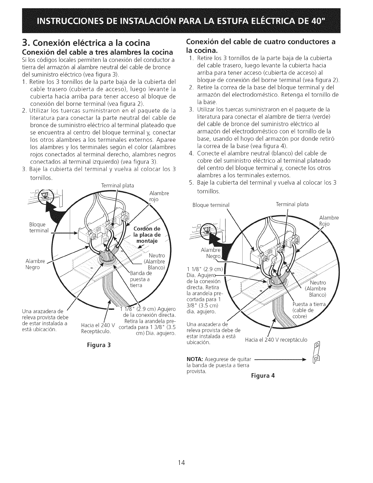
3. Conexion electrica a la cocina
Conexi6n del cable a tres alambres ia cocina
Si los c6digos locales permiten la conexi6n del conductor a
tierra del armaz6n al alambre neutral del cable de bronce
del suministro el@ctrico(vea figura 3).
1. Retire los 3 tornillos de la parte baja de la cubierta del
cable trasero (cubierta de acceso), luego levante la
cubierta hacia arriba para tener acceso al bloque de
conexi6n del borne terminal (vea figura 2).
2. Utilizar los tuercas suministraron en el paquete de la
literatura para conectar la parte neutral del cable de
bronce de suministro el_ctrico al terminal plateado que
se encuentra al centro del bloque terminal y, conectar
los otros alambres a los terminales externos. Aparee
los alambres y los terminales seg0n el color (alambres
rojos conectados al terminal derecho, alambres negros
conectados al terminal izquierdo) (vea figura 3).
3. Baje la cubierta del terminal y vuelva al colocar los 3
tornillos.
Terminalplata Alambre
rojo
Conexi6n del cable de cuatro conductores a
ia cocina.
1. Retire los 3 tornillos de la parte baja de la cubierta
del cable trasero, luego levante la cubierta hacia
arriba para tener acceso (cubierta de acceso) al
bloque de conexi6n del borne terminal (vea figura 2).
2. Retire la correa de la base del bloque terminal y del
armaz6n del electrodom@stico. Retenga el tornillo de
la base.
3. Utilizar los tuercas suministraron en el paquete de la
literatura para conectar el alambre de tierra (verde)
del cable de bronce del suministro el_ctrico al
armaz6n del electrodom@stico con el tornillo de la
base, usando el hoyo del armaz6n por donde retir6
la correa de la base (vea figura 4).
4. Conecte el alambre neutral (blanco) del cable de
cobre del suministro el@ctrico al terminal plateado
del centro del bloque terminal y, conecte los otros
alambres a los terminales externos.
S. Baje la cubierta del terminal y vuelva al colocar los 3
tornillos.
Bloque terminal Terminal plata
Bloque
terminal
Alambre
'O
Alambre
Negro
Una arazadera de
releva provista debe
de estar instalada a
est,1ubicaci6n.
1 1/8" cm) Agujero
de la conexi6n directa.
Retira la arandela pre-
Hacia el 240 V cortada para 1 3/8" (3.5
Recept_iculo. cm) Dia. agujero.
Figura 3
Alambre
Ne(
1 1/8" (2.9 cm)
Dia. A,
de la conexi6n
directa. Retira
la arandela pre-
cortada para 1
318" (3.5 cm)
dia. agujero.
Una arazadera de
releva provista debe de
estar instalada a est,1
ubicaci6n. Hacia el 240 V recept_iculo
NOTA: Asegurese de quitar
la banda de puesta a tierra
provista. Figura 4
14
Conexion electrica directa ai cortacircuito, a
ia caja de fusibles o ia caja de empalmes
Si el aparato est_Sconectado directamente al cortacircuito,
a la caja de fusibles o a la caja de empalmes, use un cable
blindado flexible o no met_qlicorecubierto de cobre (con
alambre a tierra). Provee una abrazadera releva de anclaje
hom61ogo UL a cada extremidad del cable. A la extremidad
del electrodom_stico, el cable pase a trav_s del agujero
de la conexi6n directa (vet figura 5) en el cord6n de la
placa de montaje. El tamaho de los alambres (alambre de
cobre solamente) y las conexiones deben estar conforme
al r_gimen del electrodom_stico.
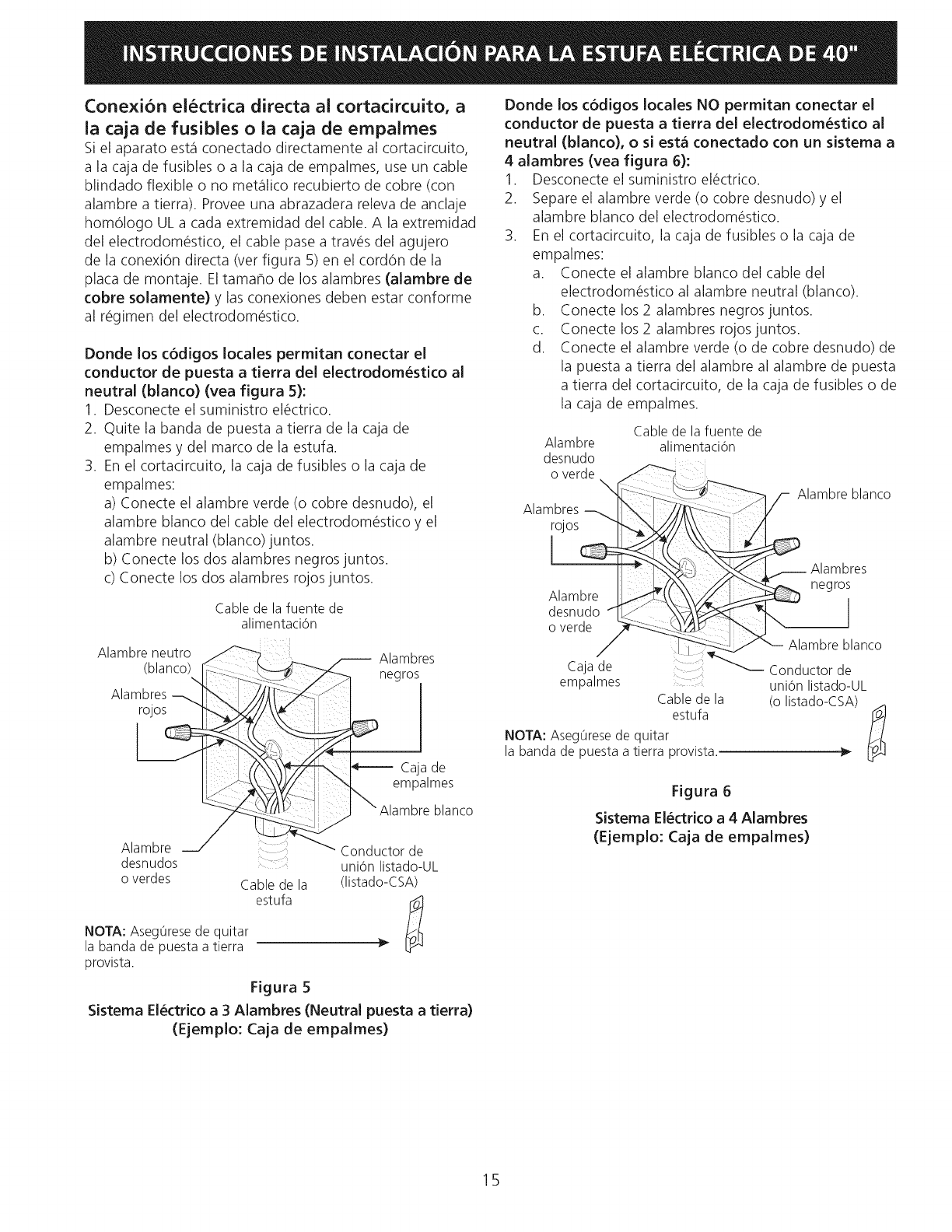
Donde los codigos locales permitan conectar el
conductor de puesta a tierra del electrodom_stico al
neutral (blanco) (vea figura 5):
1. Desconecte el suministro el_ctrico.
2. Quite la banda de puesta a tierra de la caja de
empalmes y del marco de la estufa.
3. En el cortacircuito, la caja de fusibles o la caja de
empalmes:
a) Conecte el alambre verde (o cobre desnudo), el
alambre blanco del cable del electrodom_stico y el
alambre neutral (blanco)juntos.
b) Conecte los dos alambres negros juntos.
c) Conecte los dos alambres rojos juntos.
Cable de la fuente de
alimentaciOn
Alambre neutro
(blanco)_ d
rojos _ .'-b_.//\_" [
Alambre _" !-T-_--,./
desnudos
overdes Cable de la
estufa
NOTA: Aseg0rese de quitar
la banda de puesta a tierra
provista.
Alambres
negros
._-, Caja de
empalmes
.J \Alambre blanco
Conductor de
uni6n listado-UL
(listado-CSA)
Figura 5
Sistema El_ctrico a 3 Alambres (Neutral puesta a tierra)
(Ejemplo: Caja de empalmes)
Donde los c6digos locales NO permitan conectar el
conductor de puesta a tierra del electrodom_stico al
neutral (blanco), o si est_ conectado con un sistema a
4 alambres (vea figura 6):
1. Desconecte el suministro el_ctrico.
2. Separe el alambre verde (o cobre desnudo) y el
alambre blanco del electrodom6stico.
3. En el cortacircuito, la caja de fusibles o la caja de
empalmes:
a. Conecte el alambre blanco del cable del
electrodom_stico al alambre neutral (blanco).
b. Conecte los 2 alambres negros juntos.
c. Conecte los 2 alambres rojos juntos.
d. Conecte el alambre verde (o de cobre desnudo) de
la puesta a tierra del alambre al alambre de puesta
a tierra del cortacircuito, de la caja de fusibles o de
la caja de empalmes.
Cable de la fuente de
Alambre alimentaci6n
desnudo
o verde
Alambres--_ [_'{_""-'_ <
Alambre _-._(, !
desnudo "q.L__ "_
o verde _
Caja de
empalmes
Cable de la
estufa
NOTA: Aseg0rese de quitar
la banda de puesta a tierra provista.
lambre blanco
"_ Conductor de
uni6n listado-UL
(o listado-CSA)
Figura 6
Sistema El_ctrico a 4 Alambres
(Ejemplo: Caja de empalmes)
15
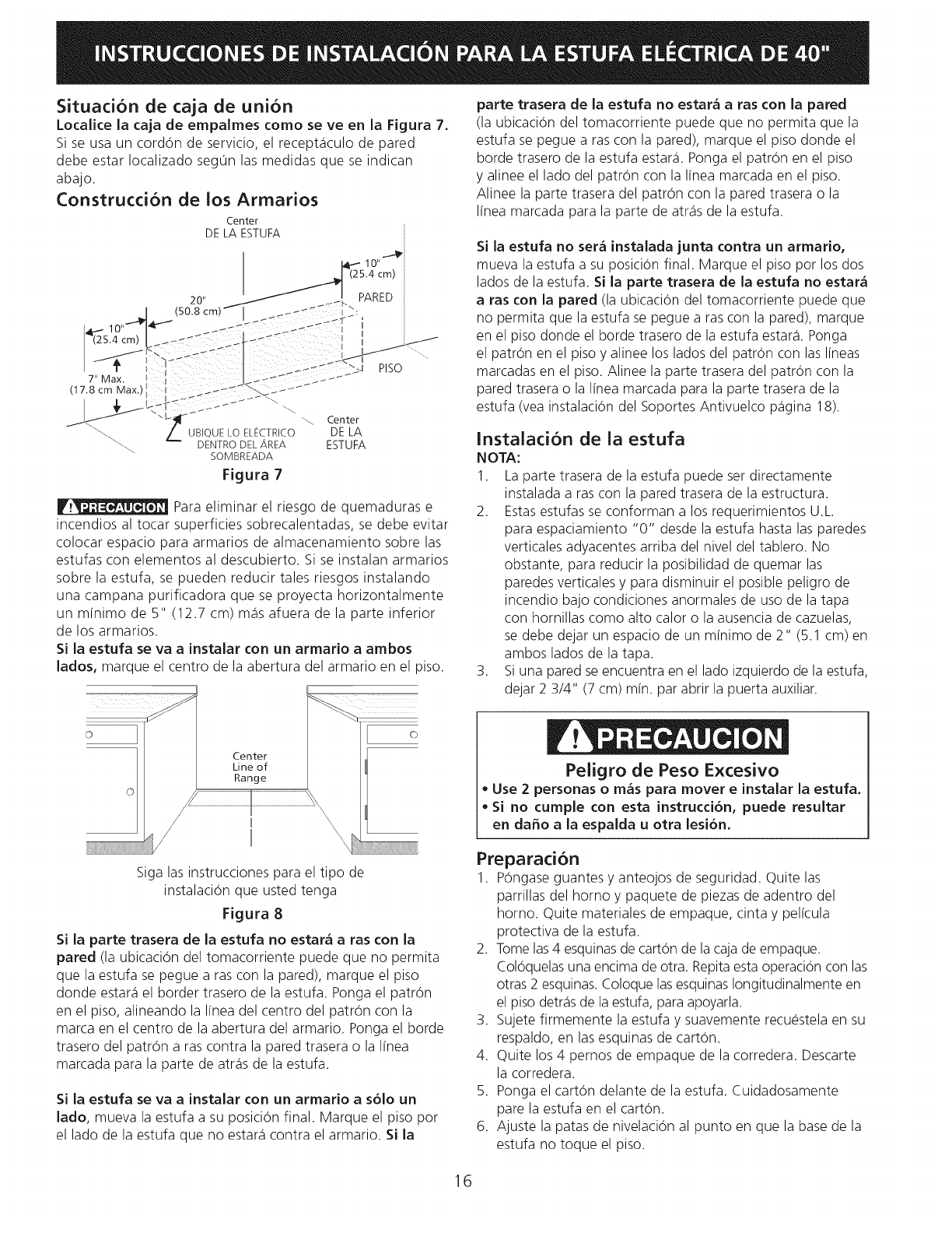
Situaci6n de caja de union
Localice la caja de empa[mes como se ve en la Figura 7.
Si se usa un cord6n de servicio, el recept_iculo de pared
debe estar Iocalizado seg0n las medidas que se indican
abajo.
ConstructiOn de los Armarios
7" Max.
(17.8 cm Max.'
_ / _ Center
UBIQUE LO EL_CTRICO DE LA
DENTRO DEL AREA ESTUFA
SOMBREADA
Figura 7
Para eliminar el riesgo de quemaduras e
incendios al tocar superficies sobrecalentadas, se debe evitar
colocar espacio para armario5 de almacenamiento sobre las
estufas con elementos al descubierto. Si se instalan armarios
sobre la estufa, se pueden reducir tales riesgos instalando
una campana purificadora que se proyecta horizontalmente
un mfnimo de 5" (12.7 cm) m_is afuera de la parte inferior
de los armarios.
Si la estufa se va a Jnstalar con un armario a ambos
lados, marque el centro de la abertura del armario en el piso.
Center
Line of
Range
I
I
Siga las instrucciones para el tipo de
instalacion que usted tenga
Figura 8
Si la parte trasera de la estufa no estar_ a ras con la
pared (la ubicacion del tomacorriente puede que no permita
que la estufa se pegue a ras con la pared), marque el piso
donde estate1el border trasero de la estufa. Ponga el patron
en el piso, alineando la linea del centro del patron con la
marca en el centro de la abertura del armario. Ponga el borde
trasero del patron a ras contra la pared trasera o la linea
marcada para la parte de atr_is de la estufa.
Si la estufa se va a Jnstalar con un armarJo a s6lo un
lado, mueva la estufa a su posicion final. Marque el piso pot
el lado de la estufa que no estate1contra el armario. Si la
parte trasera de la estufa no estar_ a ras con la pared
(la ubicacion del tomacorriente puede que no permita que la
estufa se pegue a ras con la pared), marque el pi5o donde el
borde trasero de la estufa estar& Ponga el patron en el pi5o
y alinee el lado del patron con la linea marcada en el piso.
Alinee la parte trasera del patron con la pared trasera o la
linea marcada para la parte de atr_is de la estufa.
Si la estufa no sera instalada junta contra un armarJo,
mueva la estufa a su posiciOn final. Marque el piso pot los dos
lados de la estufa. Si la parte trasera de la estufa no estara
a ras con la pared (la ubicaciOn del tomacorriente puede que
no permita que la estufa se pegue a ras con la pared), marque
en el pi5o donde el borde trasero de la estufa estar& Ponga
el patron en el piso y alinee Io5 lado5 del patron con las I[neas
marcadas en el pi5o. Alinee la parte trasera del patron con la
pared trasera o la I[nea marcada para la parte trasera de la
estufa (vea instalaciOn del Soportes Antivuelco p_igina 18).
InstaladOn de ia estufa
NOTA:
1. La parte trasera de la estufa puede set directamente
instalada a ras con la pared trasera de la estructura.
2. Estas estufas se conforman a los requerimientos U.L.
para espaciamiento "0" desde la estufa hasta las paredes
verticales adyacentes arriba del nivel del tablero. No
obstante, para reducir la posibilidad de quemar las
paredes verticales y para disminuir el posible peligro de
incendio bajo condiciones anormales de uso de la tapa
con hornillas como alto calor o la ausencia de cazuelas,
se debe dejar un espacio de un minimo de 2" (5.1 cm) en
ambos lados de la tapa.
3. Si una pared se encuentra en el lado izquierdo de la estufa,
dejar 2 3/4" (7 cm) min. par abrir la puerta auxiliar.
Peligro de Peso Excesivo
• Use 2 personas o m_s para mover e Jnstalar la estufa.
• SJ no cumple con esta JnstruccJ6n, puede resultar
en daffo a la espaJda u otra lesJ6n.
Preparaci6n
1. P6ngase guantes y anteojos de seguridad. Quite las
parrillas del homo y paquete de piezas de adentro del
homo. Quite materiales de empaque, cinta y pelicula
protectiva de la estufa.
2. Tome las 4 esquinas de carton de la caja de empaque.
Coloquelas una encima de otra. Repita esta operacion con las
otras 2 esquinas. Coloque las esquinas Iongitudinalmente en
el pi5o detr_is de la estufa, para apoyarla.
3. Sujete firmemente la estufa y suavemente recuestela en su
respaldo, en las esquinas de carton.
4. Quite Io5 4 pernos de empaque de la corredera. Descarte
la corredera.
5. Ponga el carton delante de la estufa. Cuidadosamente
pare la estufa en el carton.
6. Ajuste la patas de nivelacion al punto en que la base de la
estufa no toque el piso.
16
Nivelad6n de ia estufa
Nivele la estufa y ajuste la altura de la estufa antes de
instalarla en la abertura.
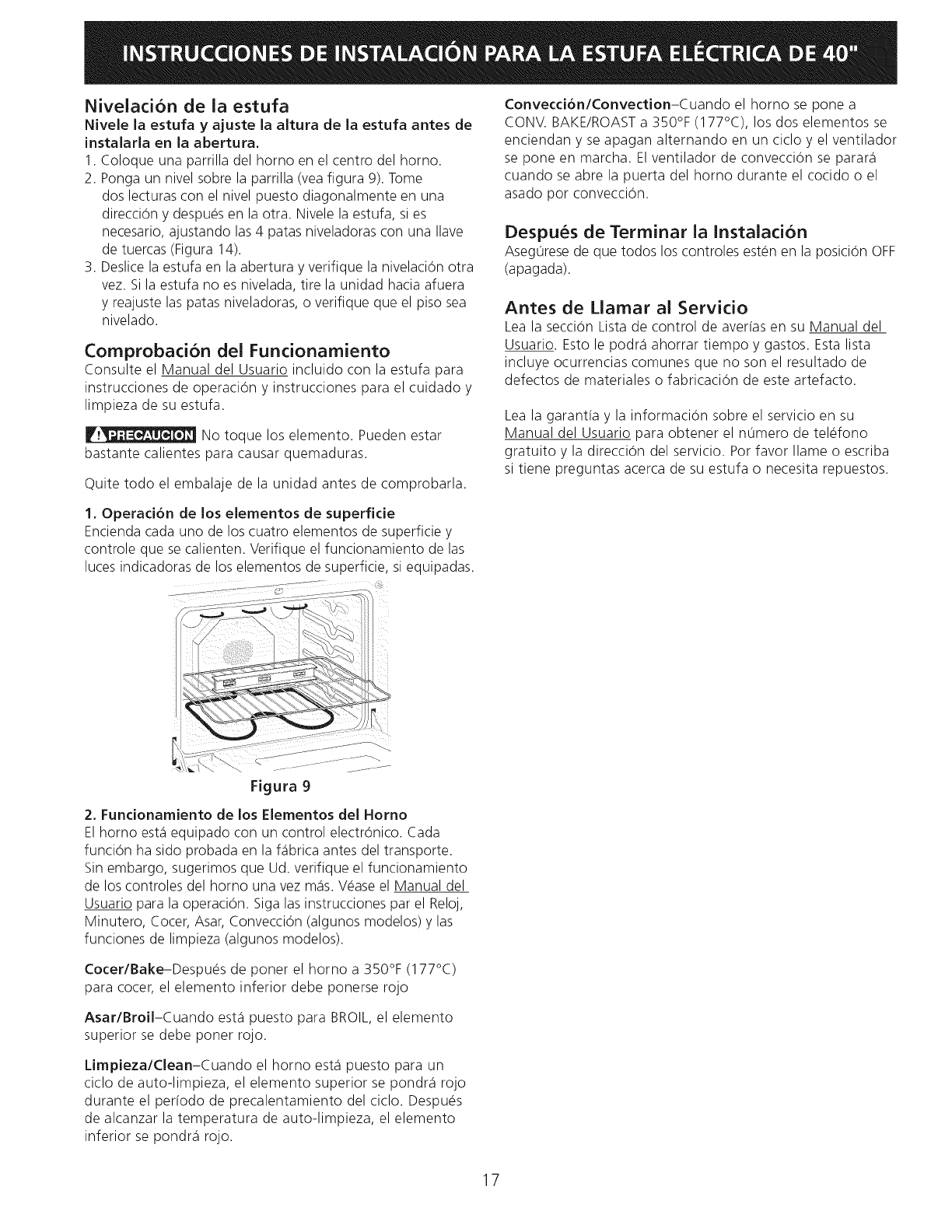
1. Coloque una parrilla del homo en el centro del homo.
2. Ponga un nivel sobre la parrilla (vea figura 9). Tome
dos lecturas con el nivel puesto diagonalmente en una
direccion y despues en la otra. Nivele la estufa, si es
necesario, ajustando las 4 patas niveladoras con una Ilave
de tuercas (Figura 14).
3. Deslice la estufa en la abertura y verifique la nivelacion otra
vez. Si la estufa no es nivelada, tire la unidad hacia afuera
y reajuste las patas niveladoras, o verifique que el piso sea
nivelado.
Comprobacion dei Funcionamiento
Consulte el Manual del Usuario incluido con la estufa para
instrucciones de operacion y instrucciones para el cuidado y
limpieza de su estufa.
No toque los elemento. Pueden estar
bastante calientes para causar quemaduras.
Quite todo el embalaje de la unidad antes de comprobarla.
Convecd6n/Convection-Cuando el homo se pone a
CONV. BAKE/ROAST a 350°F (177°C), los dos elementos se
enciendan y se apagan alternando en un ciclo y el ventilador
se pone en marcha. El ventilador de conveccion se parar_i
cuando se abre la puerta del homo durante el cocido o el
asado pot conveccion.
Despues de Terminar la Instalad6n
Aseg0rese de que todos los controles esten en la posicion OFF
(apagada).
Antes de Llamar al Servicio
Lea la secciOn Lista de control de averfas en su Manual del
Usuario. Esto le podr_i ahorrar tiempo y gastos. Esta lista
incluye ocurrencias comunes que no son el resultado de
defectos de materiales o fabricacion de este artefacto.
Lea la garant[a y la informacion sobre el servicio en su
Manual del Usuario para obtener el n0mero de telefono
gratuito y la direccion del servicio. Pot favor Ilame o escriba
si tiene preguntas acerca de su estufa o necesita repuestos.
1, Operad6n de los elementos de superfide
Encienda cada uno de los cuatro elementos de superficie y
controle que se calienten. Verifique el funcionamiento de las
luces indicadoras de los elementos de superficie, si equipadas.
Figura 9
2, Fundonamiento de los Elementos del Homo
El homo est,1 equipado con un control electronico. Cada
funcion ha sido probada en la f_ibrica antes del transporte.
Sin embargo, sugerimos que Ud. verifique el funcionamiento
de los controles del homo una vez m_is. Vease el Manual del
Usuario para la operacion. Siga las instrucciones par el Reloj,
Minutero, Cocer, Asar, Conveccion (algunos modelos) y las
funciones de limpieza (algunos modelos).
Cocer/Bake-Despues de poner el homo a 350°F (177°C)
para cocer, el elemento inferior debe ponerse rojo
Asar/BroiI-Cuando est,1 puesto para BROIL, el elemento
superior se debe poner rojo.
Limpieza/Clean-Cuando el homo est,1 puesto para un
ciclo de auto-limpieza, el elemento superior se pondr_i rojo
durante el perfodo de precalentamiento del ciclo. Despues
de alcanzar la temperatura de auto-limpieza, el elemento
inferior se pondr_i rojo.
17
8. Instruction para la instalaci6n del
braquete anti-basculante
Nota importante de seguridad
Para reducir el riesgo de inclinaciOn de la cocina, _sta debe
set asegurada hacia el piso con las fijaciones de anti-
inclinaci6n y los tornillos que vienen con la cocina. Si no
instala las fijaciones, corre el riesgo que su cocina pueda
inclinarse si pone demasiado peso sobre la puerta abierta
o si un niho sube sobre _sta. Esto podria ocasionar graves
lesiones causadas pot derrames de liquidos calientes o pot
la propria cocina.
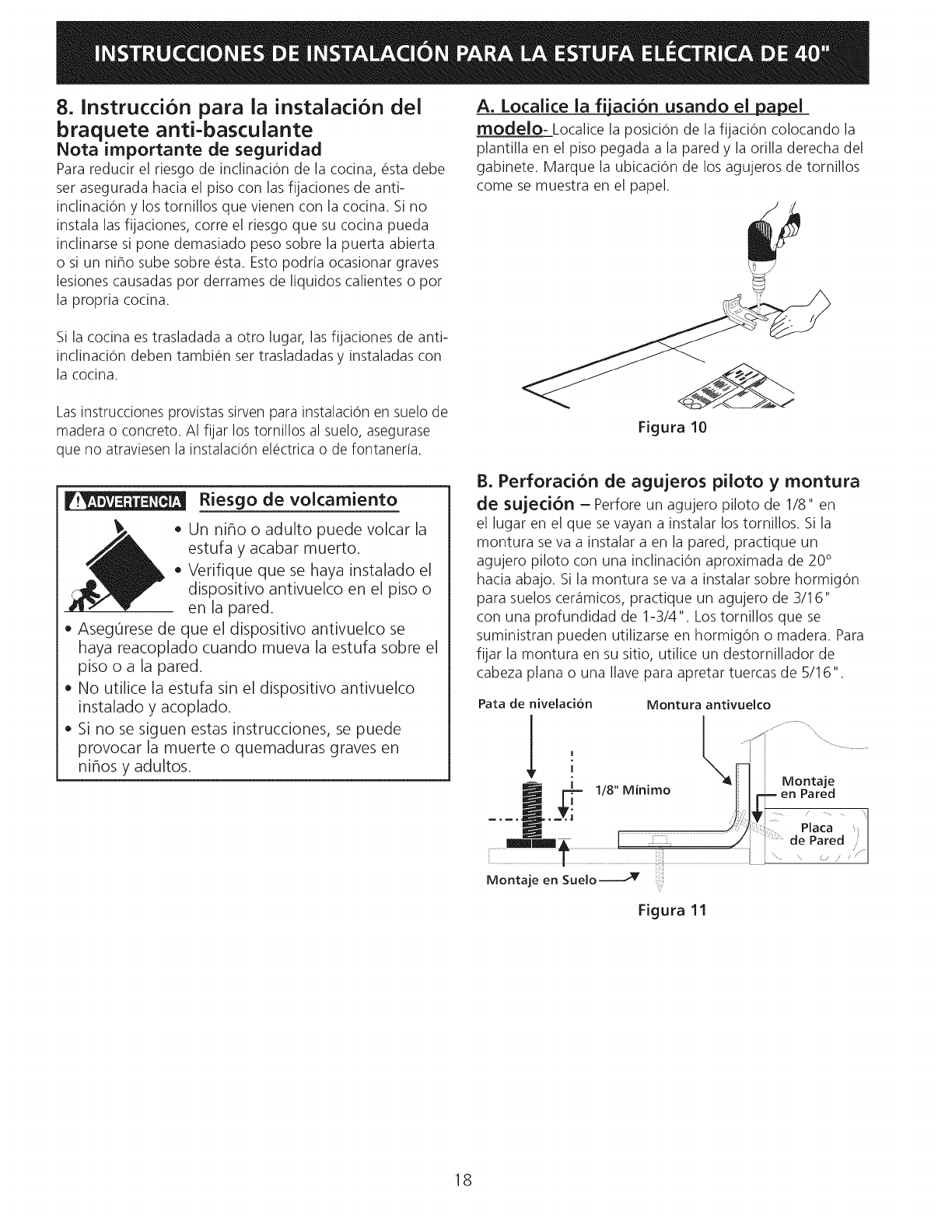
A. Localice ia fiiad6n usando el papel
modelo- Localice la posiciOn de la fijaciOn colocando la
plantilla en el piso pegada a la pared y la orilla derecha del
gabinete. Marque la ubicaci6n de los agujeros de tornillos
come se muestra en el papel.
Si la cocina es trasladada a otto lugar, las fijaciones de anti-
inclinaci6n deben tambi_n set trasladadas y instaladas con
la cocina.
Las instrucciones provistas sirven para instalaci6n en suelo de
madera o concreto. AI fijar los tornillos al suelo, asegurase
que no atraviesen la instalaci6n el_ctrica o de fontanerfa.
_r_ Riesgo de voicamiento
,, Un nino o adulto puede volcar la
estufa y acabar muerto.
,, Verifique que se haya instalado el
dispositivo antivuelco en el piso o
en la pared.
,, Asegurese de que el dispositivo antivuelco se
haya reacoplado cuando mueva la estufa sobre el
piso o a la pared.
,, No utilice la estufa sin el dispositivo antivuelco
instalado y acoplado.
,, Si no se siguen estas instrucciones, se puede
provocar la muerte o quemaduras graves en
ninos y adultos.
Figura 10
B. Perforacion de agujeros piioto y montura
de sujecion - Perfore un agujero piloto de 1/8" en
el lugar en el que se vayan a instalar los tornillos. Si la
montura se va a instalar a en la pared, practique un
agujero piloto con una inclinaci0n aproximada de 20°
hacia abajo. Si la montura se va a instalar sobre hormig0n
para suelos cer_imicos, practique un agujero de 3/16"
con una profundidad de 1-3/4". Lostornillos que se
suministran pueden utilizarse en hormigOn o madera. Para
fijar la montura en su sitio, utilice un destornillador de
cabeza plana o una llave para apretar tuercas de 5/16
Montura antivuelco
f..- --\
Montaje
en Pared
;; a ca
de Pared
\ \ ,'.J/
Figura 11
18
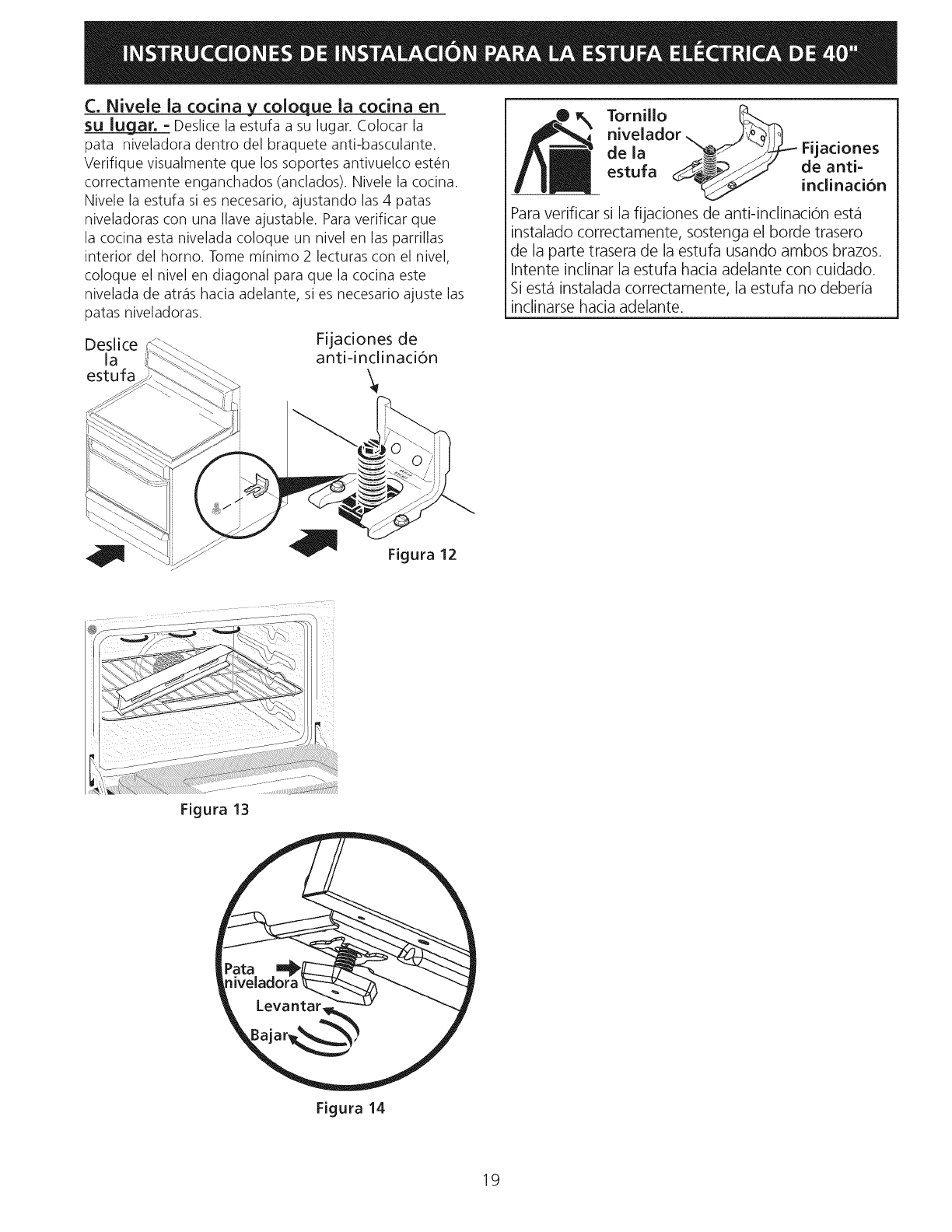
C. Nivele ia cocina ycoioque ia cocina en
SU Iugar. = Deslice la estufa a su lugar. Colocar la
pata niveladora dentro del braquete anti-basculante.
Verifique visualmente que los soportes antivuelco est_n
correctamente enganchados (anclados). Nivele la cocina.
Nivele la estufa si es necesario, ajustando las 4 patas
niveladoras con una Ilave ajustable. Para verificar que
la cocina esta nivelada coloque un nivel en las parrillas
interior del homo. Tome minimo 2 lecturas con el nivel,
coloque el nivel en diagonal para que la cocina este
nivelada de atrcis hacia adelante, si es necesario ajuste las
patas niveladoras.
Deslice Fijadones de
la anti-inclinaci6n
estufa
Tornillo _k__.._
nivelador _ _)_i!_1
de la _
estufa __
Para verificar si la fijaciones de anti-inclinacion estci
instalado correctamente, sostenga el borde trasero
de la parte trasera de la estufa usando ambos brazos.
Intente inclinar la estufa hacia adelante con cuidado.
Si estci instalada correctamente, la estufa no deberia
inclinarse hacia adelante.
Fijaciones
de anti-
inclinacion
Figura 13
Pata
Levantar
Figura 14
19

20
