Kenmore 11086562500 User Manual RESIDENTIAL DRYER Manuals And Guides L0523165
KENMORE Residential Dryer Manual L0523165 KENMORE Residential Dryer Owner's Manual, KENMORE Residential Dryer installation guides
User Manual: Kenmore 11086562500 11086562500 KENMORE RESIDENTIAL DRYER - Manuals and Guides View the owners manual for your KENMORE RESIDENTIAL DRYER #11086562500. Home:Laundry & Garment Care Parts:Kenmore Parts:Kenmore RESIDENTIAL DRYER Manual
Open the PDF directly: View PDF ![]() .
.
Page Count: 60
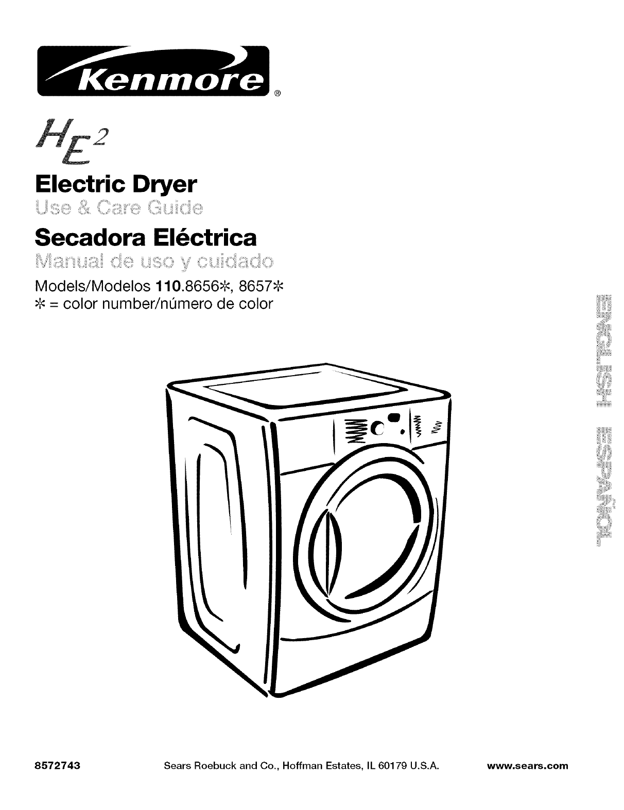
®
Electric Dryer
Secadora El_ctrica
Models/Modelos 110.8656=_, 8657_
#: = color number/nemero de color
iiiiii!Jiiiiiiiiiii!il
8572743 Sears Roebuck and Co., Hoffman Estates, IL 60179 U.S.A. www.sears.com
TABLE OF CONTENTS
PROTECTION AGREEMENTS ....................................................... 2
WARRANTY ..................................................................................... 3
PEDESTAL OPTION WARRANTY ................................................. 3
DRYER SAFETY .............................................................................. 4
INSTALLATION INSTRUCTIONS .................................................. 5
Tools and Parts ............................................................................ 5
Options ......................................................................................... 5
Location Requirements ............................................................... 5
Electrical Requirements ................................................................ 8
Electrical Connection ................................................................... 9
Venting Requirements ............................................................... 14
Plan Vent System ...................................................................... 15
Install Vent System .................................................................... 16
Install Leveling Legs .................................................................. 17
Connect Vent ............................................................................. 17
Level Dryer ................................................................................. 17
Reverse Door Swing .................................................................. 17
Complete Installation ................................................................. 19
DRYER USE ................................................................................. 20
Starting Your Dryer .................................................................... 20
Stopping or Restarting Your Dryer ............................................ 21
Lock Controls ............................................................................ 21
Loading Guide ........................................................................... 21
Drying and Cycle Tips ............................................................... 22
Status Lights .............................................................................. 22
Cycles ........................................................................................ 23
Modifiers .................................................................................... 24
Options ...................................................................................... 24
Changing Cycles, Options and Modifiers ................................. 24
TUMBLE FREETM Non-Heated Dryer Rack .............................. 25
DRYER CARE .............................................................................. 26
Cleaning the Dryer Location ...................................................... 26
Cleaning the Lint Screen ........................................................... 26
Cleaning the Dryer Interior ........................................................ 26
Removing Accumulated Lint ..................................................... 27
Vacation and Moving Care ........................................................ 27
TROUBLESHOOTING .................................................................. 28
SERVICE NUMBERS ............................................... BACK COVER
PROTECTION AGREEMENTS
Master Protection Agreements
Congratulations on making a smart purchase. Your new
Kenmore ®product is designed and manufactured for years of
dependable operation. But like all products, it may require
preventive maintenance or repair from time to time. That's when
having a Master Protection Agreement can save you money and
aggravation.
Purchase a Master Protection Agreement now and protect
yourself from unexpected hassle and expense.
The Master Protection Agreement also helps extend the life of
your new product. Here's what's included in the Agreement:
v' Expert service by our 12,000 professional repair specialists
v' Unlimited service and no charge for parts and labor on all
covered repairs
v' "No-lemon" guarantee - replacement of your covered
product if four or more product failures occur within twelve
months
v' Product replacement if your covered product can't be fixed
v' Annual Preventive Maintenance Check at your request - no
extra charge
v' Fast help by phone - phone support from a Sears technician
on products requiring in-home repair, plus convenient repair
scheduling
v' Power surge protection against electrical damage due to
power fluctuations
v' Rental reimbursement if repair of your covered product takes
longer than promised
Once you purchase the Agreement, a simple phone call is all that
it takes for you to schedule service. You can call anytime day or
night, or schedule a service appointment online.
Sears has over 12,000 professional repair specialists, who have
access to over 4.5 million quality parts and accessories. That's
the kind of professionalism you can count on to help prolong the
life of your new purchase for years to come. Purchase your
Master Protection Agreement today!
Some limitations and exclusions apply. For prices and
additional information, call 1-800-827-6655.
Sears Installation Service
For Sears professional installation of home appliances, garage
door openers, water heaters, and other major home items, in the
U.S.A. call 1-800-4-MY-HOME ®.
WARRANTY
ONE YEAR FULL WARRANTY ON HE2 DRYER
For one year from the date of purchase, when installed and
operated according to the Use & Care Guide, this dryer will be
repaired free of charge if defective in material or workmanship.
Warranty Restriction
If this dryer is used for other than private family purposes, this
warranty applies for only 90 days from the date of purchase.
Exhausting this dryer with a plastic or metal foil vent will void this
warranty.
Warranty Service
Warranty service is available by calling 1-800-4-MY-HOME ®,This
warranty applies only while this dryer is used in the United States.
This warranty gives you specific legal rights, and you may also
have other rights which vary from state to state.
Sears, Roebuck and Co.
D/817WA, Hoffman Estates, IL 60179
Product Record
In the space following, record your complete model number,
serial number, and purchase date. You can find this information
on the model and serial number label, located at the top inside
dryer door well.
Have this information available to help you quickly obtain
assistance or service when you contact Sears concerning your
appliance.
Model number 110.
Serial number
Purchase date
Save these instructions and your sales receipt for future
reference.
PEDESTAL OPTION
WARRANTY
One Year Full Warranty on Pedestal
For one year from the date of purchase, when installed according
to its Installation Instructions, this pedestal will be repaired or
replaced free of charge if it is defective in material or
workmanship.
Warranty Restriction
This warranty is void if this pedestal is used for other than private
family purposes, or used with any other product than those listed
in its Installation Instructions.
Warranty Service
Warranty service is available by calling 1-800-4-MY-HOME ®.This
warranty applies only while this pedestal is used in the United
States or Canada. This warranty gives you specific legal rights,
and you may also have other rights which vary from state to
state.
In the space following, record your complete model number,
serial number, and purchase date. You can find this information
on the model and serial number label.
Have this information available to help you quickly obtain
assistance or service when you contact Sears concerning your
appliance.
Model number 110.
Serial number
Purchase date
Save these instructions and your sales receipt for future
reference.
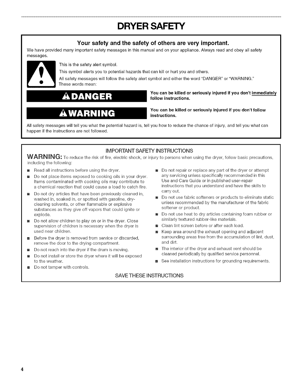
DRYER SAFETY
Your safety and the safety of others are very important.
We have provided many important safety messages in this manual and on your appliance. Always read and obey all safety
messages.
This is the safety alert symbol.
This symbol alerts you to potential hazards that can kill or hurt you and others.
All safety messages will follow the safety alert symbol and either the word "DANGER" or "WARNING."
These words mean:
You can be killed or seriously injured if you don't immediately
follow instructions.
You can be killed or seriously injured if you don't follow
instructions.
All safety messages will tell you what the potential hazard is, tell you how to reduce the chance of injury, and tell you what can
happen if the instructions are not followed.
iMPORTANT SAFETY iNSTRUCTiONS
WARNING: To reduce the risk of fire, electric shock, or injury to persons when using the dryer, follow basic precautions,
including the following:
m Read all instructions before using the dryer.
m Do not ptace items exposed to cooking oiIs in your dryer.
items contaminated with cooking oils may contribute to
a chemicat reaction that could cause a load to catch fire.
m Do not dry articles that have been previously cleaned in,
washed in, soaked in, or spotted with gasoline, dry-
cleaning solvents, or other flammable or explosive
substances as they give off vapors that could ignite or
explode.
m Do not allow children to play on or in the dryer. Close
supervision of children is necessary when the dryer is
used near children.
m Before the dryer is removed from service or discarded,
remove the door to the drying compartment.
m Do not reach into the dryer if the drum is moving.
m Do not install or store the dryer where it will be exposed
to the weather.
m Do not tamper with controls.
m Do not repair or replace any part of the dryer or attempt
any servicing unless specifically recommended in this
Use and Care Guide or in published user-repair
instructions that you understand and have the skills to
carry out.
m Do not use fabric softeners or products to eliminate static
unless recommended by the manufacturer of the fabric
softener or product.
m Do not use heat to dry articles containing foam rubber or
similariy textured rubber-like materials.
,, Clean lint screen before or after each load.
m Keep area around the exhaust opening and adjacent
surrounding areas free from the accumulation of lint, dust,
and dirt.
The interior of the dryer and exhaust vent should be
cleaned periodicaily by qualified service personnel.
See installation instructions for grounding requirements.
SAVE THESE INSTRUCTIONS
INSTALLATION INSTRUCTIONS
Gather the required tools and parts before starting installation.
Read and follow the safety instructions provided with any tools
listed here.
• Flat-blade screwdriver • Vent clamps
• #2 Phillips screwdriver • Caulking gun and
compound (for installing
• Adjustable wrench that
opens to 1" (2.54 cm) or new exhaust vent)
hex-head socket wrench • Tin snips (new vent
(for adjusting dryer feet) installations)
• Wire stripper (direct wire • 1A" nut driver or socket
installations) wrench (recommended)
• Level • Tape measure
Parts supplied
Remove parts package from dryer drum. Check that all parts are
included.
4 Leveling legs
NOTE: Do not use leveling legs if installing the dryer on a
pedestal.
Parts needed
Check local codes. Check existing electrical supply and venting.
See "Electrical Requirements" and "Venting Requirements"
before purchasing parts.
• For close-clearance installations between 28.65" (72.77 cm)
and 34.15" (86.74 cm), see "Plan Vent System" section for
venting requirements.
(86.74 cm)
Mobile home installations require metal exhaust system hardware
available for purchase from your local Sears store or Sears
Service Center. For further information, please call
1-80O-4-MY-HOME ®(1-800-469-4663).
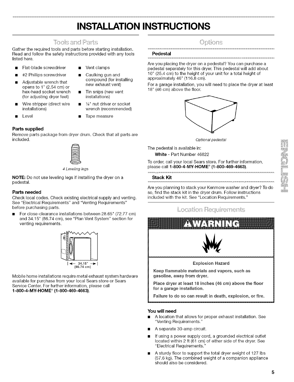
Pedestal
Are you placing the dryer on a pedestal? You can purchase a
pedestal separately for this dryer. This pedestal will add about
10" (25.4 cm) to the height of your unit for a total height of
approximately 46" (116.8 cm).
For a garage installation, you will need to place the dryer at least
18" (46 cm) above the floor.
Optional pedestal
The pedestal is available in:
White - Part Number 46822
To order, call your local Sears store. For further information,
please call 1-80O-4-MY-HOME ®(1-800-469-4663).
ackK.
Are you planning to stack your Kenmore washer and dryer? To do
so, find the stack kit in the dryer drum. Follow instructions
included with the kit. See "Location Requirements."
Exp(os(on Hazard
Keep flammable mateda(s and vapors, such as
gasoUne, away from dryer.
P_ace dryer at (east 18 (riches (48 cm) above the floor
for a garage installation.
Fai(ure to do so can result in death, explosion, or fire°
You will need
• A location that allows for proper exhaust installation. See
"Venting Requirements."
• A separate 30-amp circuit.
• If using a power supply cord, a grounded electrical outlet
located within 2 ft (61 cm) of either side of the dryer. See
"Electrical Requirements."
• A sturdy floor to support the total dryer weight of 127 Ibs
(57.6 kg). The combined weight of a companion appliance
should also be considered.
Alevelfloorwithamaximumslopeof1"(2.5cm)underentire
dryer.(Ifslopeisgreaterthan1"[2.5cm],installExtended
DryerFeetKit,PartNo.279810.)Clothesmaynottumble
properlyandautomaticsensorcyclesmaynotoperate
correctlyifdryerisnotlevel.
• Foragarageinstallation,youwillneedtoplacethedryerat
least18"(46cm)abovethefloor.Ifusingapedestal,youwill
need18"(46cm)tothebottomofthedryer.
Donotoperateyourdryerattemperaturesbelow45°F(7°C).At
lowertemperatures,thedryermightnotshutoffattheendofan
automaticcycle.Dryingtimescanbeextended.
Thedryermustnotbeinstalledorstoredinanareawhereitwill
beexposedtowaterand/orweather.
Checkcoderequirements.Somecodeslimit,ordonotpermit,
installationofthedryeringarages,closets,mobilehomesor
sleepingquarters.Contactyourlocalbuildinginspector.
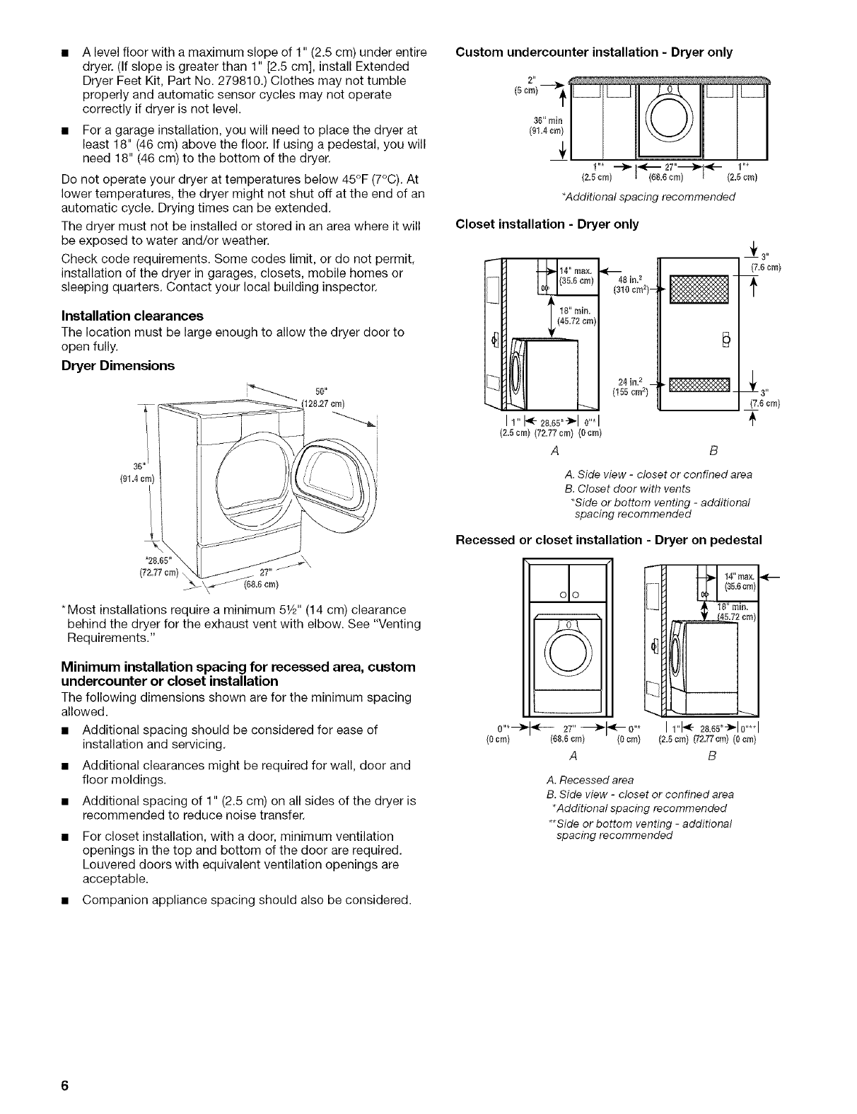
Installation clearances
The location must be large enough to allow the dryer door to
open fully.
Dryer Dimensions
36" I
{91=4cm)
'2&65"
(72=77cm)
*Most installations require a minimum 51/2'' (14 cm) clearance
behind the dryer for the exhaust vent with elbow. See "Venting
Requirements."
Minimum installation spacing for recessed area, custom
undercounter or closet installation
The following dimensions shown are for the minimum spacing
allowed.
• Additional spacing should be considered for ease of
installation and servicing.
• Additional clearances might be required for wall, door and
floor moldings.
• Additional spacing of 1" (2.5 cm) on all sides of the dryer is
recommended to reduce noise transfer.
For closet installation, with a door, minimum ventilation
openings in the top and bottom of the door are required.
Louvered doors with equivalent ventilation openings are
acceptable.
• Companion appliance spacing should also be considered.
Custom undercounter installation -Dryer only
(5cm) t
36"rain IIII
1"* _ _ 27"-----_--- 1"*
2=5¢m 68=6 ¢m {2=5 cm)
*Additional spacing recommended
Closet installation -Dryer only
II "1111_1111 I I24in? _
LCI I LI ,,0,oro2,
11"t<-28,65"_"10"*I
{2=5cm} (72=77¢m} (0¢m)
A B
(7=6cm)
A. Side view -closet or confined area
B. Closet door with vents
*Side or bottom venting -additional
spacing recommended
Recessed or closet installation - Dryer on pedestal
(0ore} ,,F- 27"---_1"-0"* Irl* 28=65"_'10....
(68.6cm) (0cm) (2.5cm) _'2.77cm} (0cm)
A B
A. Recessed area
B. Side view -closet or confined area
*Additional spacing recommended
**Side or bottom venting -additional
spacing recommended
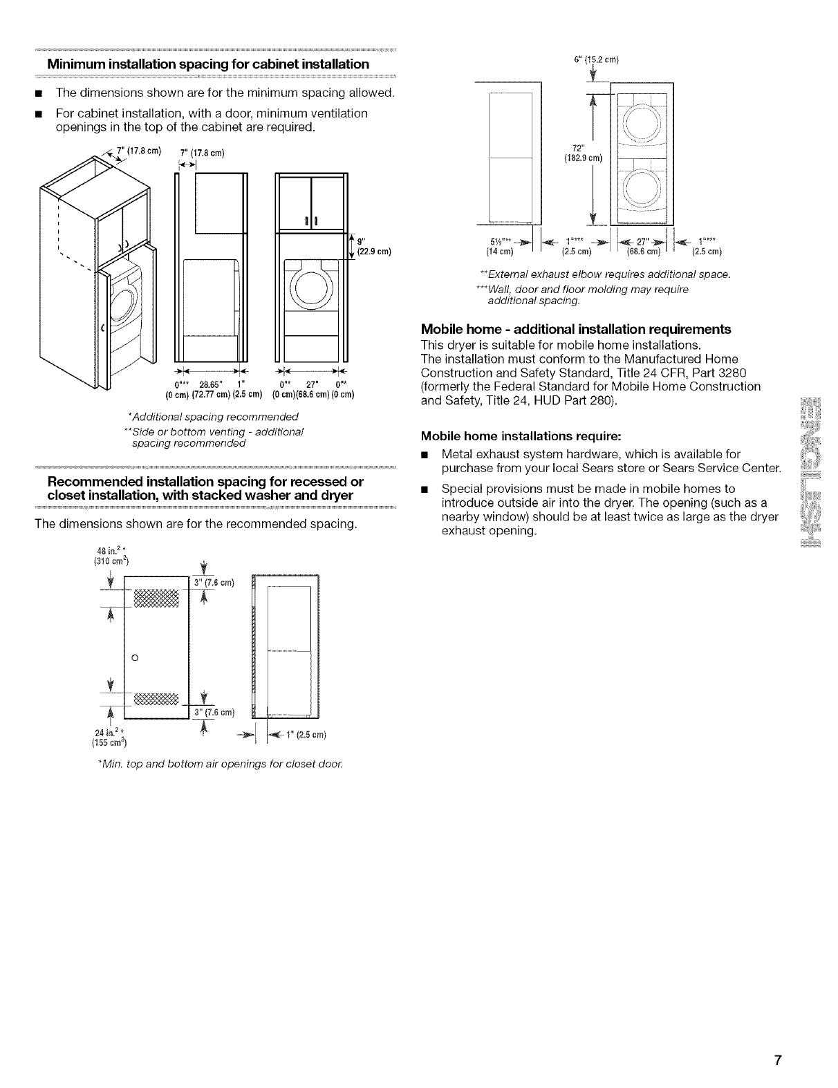
Minimum installation spacing for cabinet installation
• The dimensions shown are for the minimum spacing allowed.
• For cabinet installation, with a door, minimum ventilation
openings in the top of the cabinet are required.
", ) 7"(17.8 crn)
a!
_;'29 crn)
0 !* 2865 0 * 27 0 *
(0cm) (72.77cm)(2.5cm) (0cm)(68.6cm)(0cm)
*Additional spacing recommended
**Side or bottom venting -additional
spacing recommended
Recommended installation spacing for recessed or
closet installation, with stacked washer and dryer
The dimensions shown are for the recommended spacing.
48 in=_*
{310 ¢m _}
24 in=_*
(155cm_)
•Min. top and bottom air openings for closet doo_
3"(7,_cm)
3" (7=6cm)
-m_ _,_ 1" (2.5cm)
5Y2"** ==}1_
14 cm
6" {_m)
72"
(182.9 cm)
1"*** -_
{2=5cm) _-27"=;_ _ I "***
68=6cm 2=5cm
**External exhaust elbow requires additional space.
***Wall, door and floor molding may require
additional spacing.
Mobile home -additional installation requirements
This dryer is suitable for mobile home installations.
The installation must conform to the Manufactured Home
Construction and Safety Standard, Title 24 CFR, Part 3280
(formerly the Federal Standard for Mobile Home Construction
and Safety, Title 24, HUD Part 280).
Mobile home installations require:
• Metal exhaust system hardware, which is available for
purchase from your local Sears store or Sears Service Center.
Special provisions must be made in mobile homes to
introduce outside air into the dryer. The opening (such as a
nearby window) should be at least twice as large as the dryer
exhaust opening.
It is your responsibility
•To contact a qualified electrical installer.
•To be sure that the electrical connection is adequate and in
conformance with the National Electrical Code, ANSl/NFPA
70-latest edition and all local codes and ordinances.
The National Electric Code requires a 4-wire supply
connection for homes built after 1996, dryer circuits involved
in remodeling after 1996, and all mobile home installations.
A copy of the above code standards can be obtained from:
National Fire Protection Association, One Batterymarch Park,
Quincy, MA 02269.
To supply the required 3 or 4 wire, single phase, 120/240 volt,
60 Hz., AC only electrical supply (or 3 or 4 wire, 120/208 volt
electrical supply, if specified on the serial/rating plate) on a
separate 30-amp circuit, fused on both sides of the line. A
time-delay fuse or circuit breaker is recommended. Connect
to an individual branch circuit. Do not have a fuse in the
neutral or grounding circuit.
• Do not use an extension cord.
• If codes permit and a separate ground wire is used, it is
recommended that a qualified electrician determine that the
ground path is adequate.
Electrical Connection
To properly install your dryer, you must determine the type of
electrical connection you will be using and follow the instructions
provided for it here.
• This dryer is manufactured ready to install with a 3-wire
electrical supply connection. The neutral ground wire is
permanently connected to the neutral conductor (white wire)
within the dryer. If the dryer is installed with a 4-wire electrical
supply connection, the neutral ground wire must be removed
from the external ground conductor screw (green screw), and
secured under the neutral terminal (center or white wire) of
the terminal block. When the neutral ground wire is secured
under the neutral terminal (center or white wire) of the
terminal block, the dryer cabinet is isolated from the neutral
conductor.
• If local codes do not permit the connection of a neutral
ground wire to the neutral wire, see "Optional 3-wire
connection" section.
A 4-wire power supply connection must be used when the
appliance is installed in a location where grounding through
the neutral conductor is prohibited. Grounding through the
neutral is prohibited for (1) new branch-circuit installations,
(2) mobile homes, (3) recreational vehicles, and (4) areas
where local codes prohibit grounding through the neutral
conductors.
If using a power supply cord:
Use a UL listed power supply cord kit marked for use with
clothes dryers. The kit should contain:
• A UL listed 30-amp power supply cord, rated
120/240 volt minimum. The cord should be type SRD or
SRDT and be at least 4 ft (1.22 m) long. The wires that
connect to the dryer must end in ring terminals or spade
terminals with upturned ends.
• A UL listed strain relief.
If your outlet looks like this:
4-wire receptacle (14-30R)
Then choose a 4-wire power supply cord with ring or spade
terminals and UL listed strain relief. The 4-wire power supply
cord, at least 4 ft (1.22 m) long, must have four 10-gauge copper
wires and match a 4-wire receptacle of NEMA Type
14-30R. The ground wire (ground conductor) may be either green
or bare. The neutral conductor must be identified by a white
cover.
If your outlet looks like this:
3-wire receptacle (10-30R)
Then choose a 3-wire power supply cord with ring or spade
terminals and UL listed strain relief. The 3-wire power supply
cord, at least 4 ft (1.22 m) long, must have three 10-gauge copper
wires and match a 3-wire receptacle of NEMA Type 10-30R.
If connecting by direct wire:
Power supply cable must match power supply (4-wire or 3-wire)
and be:
• Flexible armored cable or nonmetallic sheathed copper cable
(with ground wire), protected with flexible metallic conduit. All
current-carrying wires must be insulated.
• 10-gauge solid copper wire (do not use aluminum).
• At least 5 ft (1.52 m) long.
GROUNDING iNSTRUCTiONS
_' For a grounded, cord-connected dryer:
This dryer must be grounded. Hnthe event of malfunction or
breakdown, grounding will reduce the risk of electric shock
by providing a path of least resistance for eiectdc current.
This dryer uses a cord having an equipment-grounding
conductor and a grounding plug. The plug must be plugged
into an appropriate outlet that (s properly installed and
grounded in accordance with all (ocal codes and ordinances.
For a permanently connected dryer:
This dryer must be connected to a grounded metal,
permanent wiring system, or an equipment-grounding
conductor must be run with the circuit conductors and
connected to the equipment-grounding terminal or (ead on
the dryer.
WARNING: Hmproper connection of the equipment-
grounding conductor can result in a risk of electric shock.
Check with a qualified electrician or service representative
or personnel if you are in doubt as to whether the dryer is
properly grounded. Do not modify the plug on the power
suppiy cord: if it will not fit the outlet, have a proper outlet
installed by a quaiified electrician.
SAVE THESE (NSTRUCT(ONS
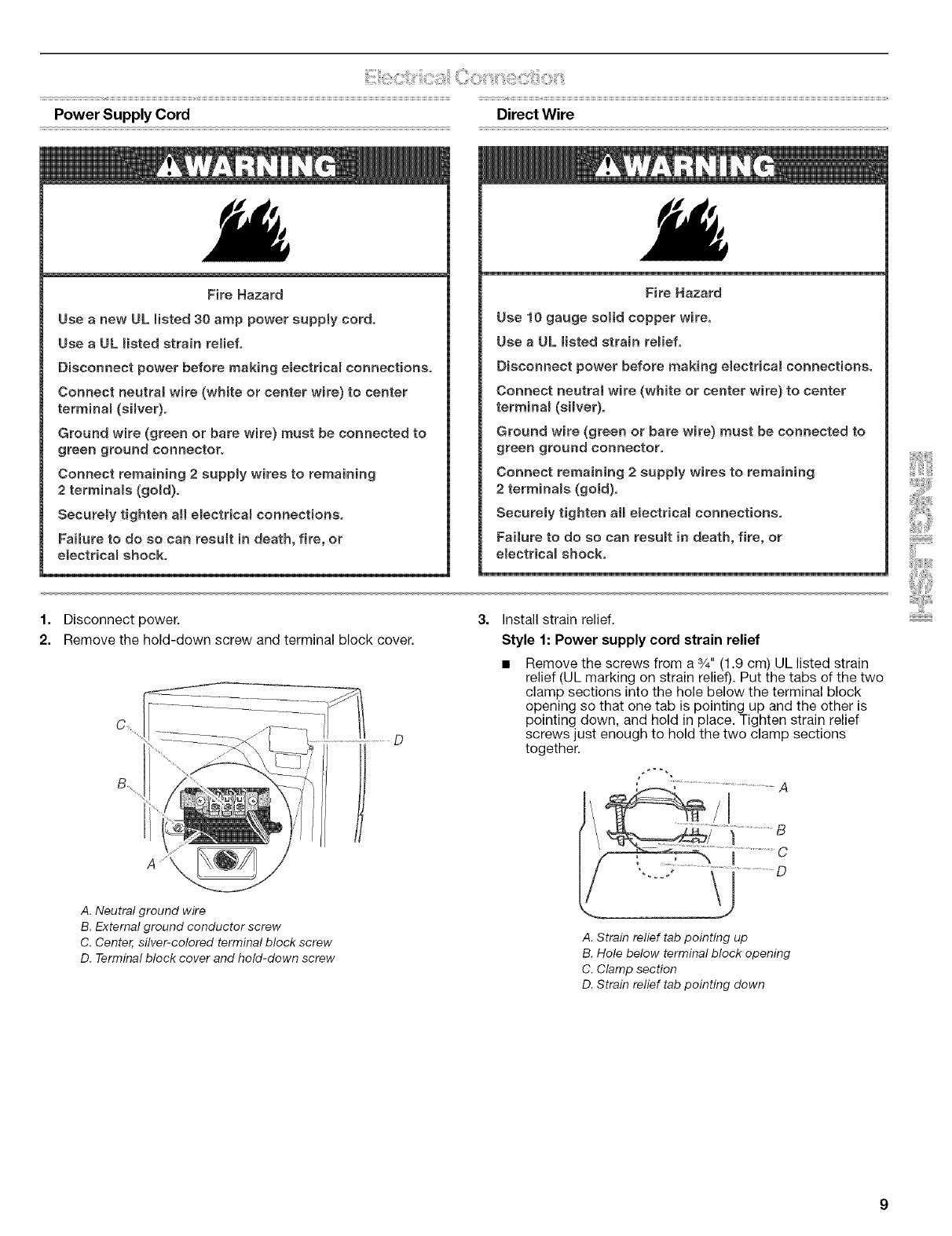
Power Supply Cord Direct Wire
Fire Hazard
Use a new UL listed 30 amp power supply cord,
Use a UL listed strain retiefo
Disconnect power before making e_ectrical connections,
Connect neutrat wire (white or center wire) to center
terminal (silver).
Ground wire (green or bare wire) must be connected to
green ground connector.
Connect remaining 2 supply wires to remaining
2terminals (gold).
Securety tighten al electrical connections,
Failure to do so can result in death, fire, or
electrical shock.
Fire Hazard
Use 10 gauge solid copper wire,
Use a UL listed strain relief,
Disconnect power before making electrical connections.
Connect neutral wire (white or center wire) to center
terminal (silver).
Ground wire (green or bare wire) must be connected to
green ground connector,
Connect remaining 2 supply wires to remaining
2 terminals (gold).
Securety tighten all electrical connections,
Failure to do so can result in death, fire, or
electrical shock,
1. Disconnect power.
2. Remove the hold-down screw and terminal block cover.
D
3. Install strain relief.
Style 1: Power supply cord strain relief
Remove the screws from a %" (1.9 cm) UL listed strain
relief (UL marking on strain relief). Put the tabs of the two
clamp sections into the hole below the terminal block
opening so that one tab is pointing up and the other is
pointing down, and hold in place. Tighten strain relief
screws just enough to hold the two clamp sections
together.
/
A. Neutral ground wire
B. External ground conductor screw
C. Center, silver-colored terminal block screw
D. Terminal block cover and hold-down screw
A. Strain relief tab pointing up
B. Hole below terminal block opening
C. Clamp section
D. Strain relief tab pointing down
Put power supply cord through the strain relief. Be sure
that the wire insulation on the power supply cord is inside
the strain relief. The strain relief should have a tight fit with
the dryer cabinet and be in a horizontal position. Do not
further tighten strain relief screws at this point.
Style 2: Direct wire strain relief
Unscrew the removable conduit connector and any
screws from a 3/4"(1.9 cm) UL listed strain relief (UL
marking on strain relief). Put the threaded section of the
strain relief through the hole below the terminal block
opening. Reaching inside the terminal block opening,
screw the removable conduit connector onto the strain
relief threads.
A
B
....................... C
A. Removable conduit connector
B. Hole below terminal block opening
C. Strain relief threads
Put direct wire cable through the strain relief. The strain
relief should have a tight fit with the dryer cabinet and be
in a horizontal position. Tighten strain relief screw against
the direct wire cable.
Electrical Connection Options
If your home has: And you will be Go to Section
connecting to:
4-wire receptacle A UL listed, 4-wire connection:
(NEMA Type 14-30R) 120/240-volt Power supply cord
minimum,
30-amp, dryer
power supply
cord*
4-wire direct A fused 4-wire connection:
disconnect or Direct Wire
circuit breaker
box*
(12.7 cm)
3-wire receptacle A UL listed,
(NEMA type 10-30R) 120/240-volt
minimum,
30-amp, dryer
power supply
cord*
3-wire connection:
Power supply cord
3-wire direct A fused 3-wire connection:
disconnect or Direct Wire
circuit breaker
box*
* If local codes do not permit the connection of a cabinet-ground
conductor to the neutral wire, go to "Optional
3-wire connection" section.
4-wire connection: Power supply cord
IMPORTANT: A 4-wire connection is required for mobile homes
and where local codes do not permit the use of 3-wire
connections.
B F
CD G
A. 4-wire receptacle (NEMA type !4-30R)
B. 4-prong plug
C. Ground prong
D. Neutralprong
E. Spade terminals with upturned ends
F.s_,,(1.9 cm) UL listed strain relief
G. Ring terminals
4= Now complete installation following instructions for your type
of electrical connection:
4-wire (recommended)
3-wire (if 4-wire is not available)
10
1=
2.
Remove center silver-colored terminal block screw.
Remove neutral ground wire from external ground conductor
screw. Connect neutral ground wire and the neutral wire
(white or center wire) of power supply cord under center,
silver-colored terminal block screw. Tighten screw.
4-wire connection: Direct wire
IMPORTANT: A 4-wire connection is required for mobile homes
and where local codes do not permit the use of 3-wire
connections.
Direct wire cable must have 5 ft (1.52 m) of extra length so dryer
can be moved if needed.
Strip 5" (12.7 cm) of outer covering from end of cable, leaving
bare ground wire at 5" (12.7 cm). Cut 11/2'' (3.8 cm) from
3 remaining wires. Strip insulation back 1" (2.5 cm). Shape ends
of wires into a hook shape.
A. External ground conductor screw -Dotted line shows
position of NEUTRAL ground wire before being moved to
center silver-colored terminal block screw
B. Center silver-colored terminal block screw
C. Neutral ground wire
D. Neutral wire (white or center wire)
E. s/4"(1.9 cm) UL listed strain relief
Connect ground wire (green or bare) of power supply cord to
external ground conductor screw. Tighten screw.
When connecting to the terminal block, place the hooked end of
the wire under the screw of the terminal block (hook facing right),
squeeze hooked end together and tighten screw, as shown.
1=
2.
Remove center silver-colored terminal block screw.
Remove neutral ground wire from external ground conductor
screw. Connect neutral ground wire and place the hooked
end (hook facing right) of the neutral wire (white or center
wire) of direct wire cable under the center screw of the
terminal block. Squeeze hooked ends together. Tighten
screw.
A. External ground conductor screw
B. Ground wire (green or bare) of power supply cord
C. 3/4"(!.9 cm) UL listed strain relief
D. Center silver-colored terminal block screw
E. Neutral ground wire
ENeutral wire (white or center wire)
4. Connect the other wires to outer terminal block screws.
Tighten screws.
5. Tighten strain relief screws.
6. Insert tab of terminal block cover into slot of dryer rear panel.
Secure cover with hold-down screw.
7. You have completed your electrical connection. Now go to
"Venting Requirements."
A..............
\
A. External ground conductor screw - Dotted line shows
position of NEUTRAL ground wire before being moved to
center silver-colored terminal block screw
B. Center silver-colored terminal block screw
C. Neutral ground wire
D. Neutral wire (white or center wire)
E. 3/4"(1.9 cm) UL listed strain relief
11
3= Connect ground wire (green or bare) of direct wire cable to
external ground conductor screw. Tighten screw.
1=
2.
Loosen or remove center silver-colored terminal block screw.
Connect neutral wire (white or center wire) of power supply
cord to the center, silver-colored terminal screw of the
terminal block. Tighten screw.
A. External ground conductor screw
B. Ground wire (green or bare) of power supply cord
C. 3/4"(1.9 cm) UL Iisted strain relief
D. Center silver-colored terminal block screw
E. Neutral ground wire
FNeutral wire (white or center wire)
4= Place the hooked ends of the other direct wire cable wires
under the outer terminal block screws (hooks facing right).
Squeeze hooked ends together. Tighten screws.
!! !!
5. Tighten strain relief screw.
6. Insert tab of terminal block cover into slot of dryer rear panel.
Secure cover with hold-down screw.
7. You have completed your electrical connection. Now go to
"Venting Requirements."
3-wire connection: Power supply cord
Use where local codes permit connecting cabinet-ground
conductor to neutral wire.
B D E
A. 3-wire receptacle (NEMA type !0-30R)
B. 3-wire plug
C. Ground prong
D. Spade terminals with up turned ends
E. 3/4"(1.9 cm) UL Iisted strain relief
ERing terminals
G. Neutral (white or center wire)
G F
A. External ground conductor screw
B.Neutral ground wire
C. Center silver-colored terminal block screw
D.Neutral wire (white er center wire)
E.3/4"(1.9cm) UL Iisted strain relief
3. Connect the other wires to outer terminal block screws.
Tighten screws.
4. Tighten strain relief screws.
5. Insert tab of terminal block cover into slot of dryer rear panel.
Secure cover with hold-down screw.
6. You have completed your electrical connection. Now go to
"Venting Requirements."
3-wire connection: Direct wire
Use where local codes permit connecting cabinet-ground
conductor to neutral wire.
Direct wire cable must have 5 ft (1.52 m) of extra length so dryer
can be moved if needed.
Strip 31/_'' (8.9 cm) of outer covering from end of cable. Strip
insulation back 1" (2.5 cm). If using 3-wire cable with ground
wire, cut bare wire even with outer covering. Shape ends of wires
into a hook shape.
When connecting to the terminal block, place the hooked end of
the wire under the screw of the terminal block (hook facing right),
squeeze hooked end together and tighten screw, as shown.
12
1=
2.
Loosen or remove center silver-colored terminal block screw.
Place the hooked end of the neutral wire (white or center wire)
of direct wire cable under the center screw of terminal block
(hook facing right). Squeeze hooked end together. Tighten
screw.
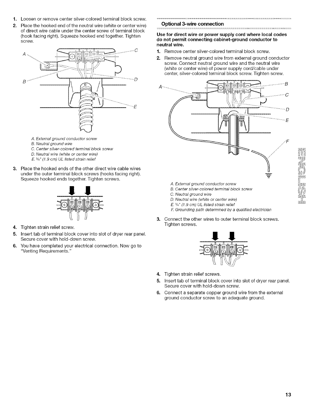
Optional 3-wire connection
Use for direct wire or power supply cord where local codes
do not permit connecting cabinet-ground conductor to
neutral wire.
1. Remove center silver-colored terminal block screw.
2. Remove neutral ground wire from external ground conductor
screw. Connect neutral ground wire and the neutral wire
(white or center wire) of power supply cord/cable under
center, silver-colored terminal block screw. Tighten screw.
A. External ground conductor screw
B. Neutral ground wire
C. Center silver-colored terminal block screw
D. Neutral wire (white or center wire)
E. 3/4"(!.9 cm) UL listed strain relief
Place the hooked ends of the other direct wire cable wires
under the outer terminal block screws (hooks facing right).
Squeeze hooked ends together. Tighten screws.
!! !!
4. Tighten strain relief screw.
5. Insert tab of terminal block cover into slot of dryer rear panel.
Secure cover with hold-down screw.
6. You have completed your electrical connection. Now go to
"Venting Requirements."
A. External ground conductor screw
B. Center silver-colored terminal block screw
C. Neutral ground wire
D. Neutral wire (white or center wire)
E. 3/4"(!.9 cm) UL listed strain relief
FGrounding path determined by a qualified electrician
Connect the other wires to outer terminal block screws.
Tighten screws.
!! !!
4. Tighten strain relief screws.
5. Insert tab of terminal block cover into slot of dryer rear panel.
Secure cover with hold-down screw.
6. Connect a separate copper ground wire from the external
ground conductor screw to an adequate ground.
13
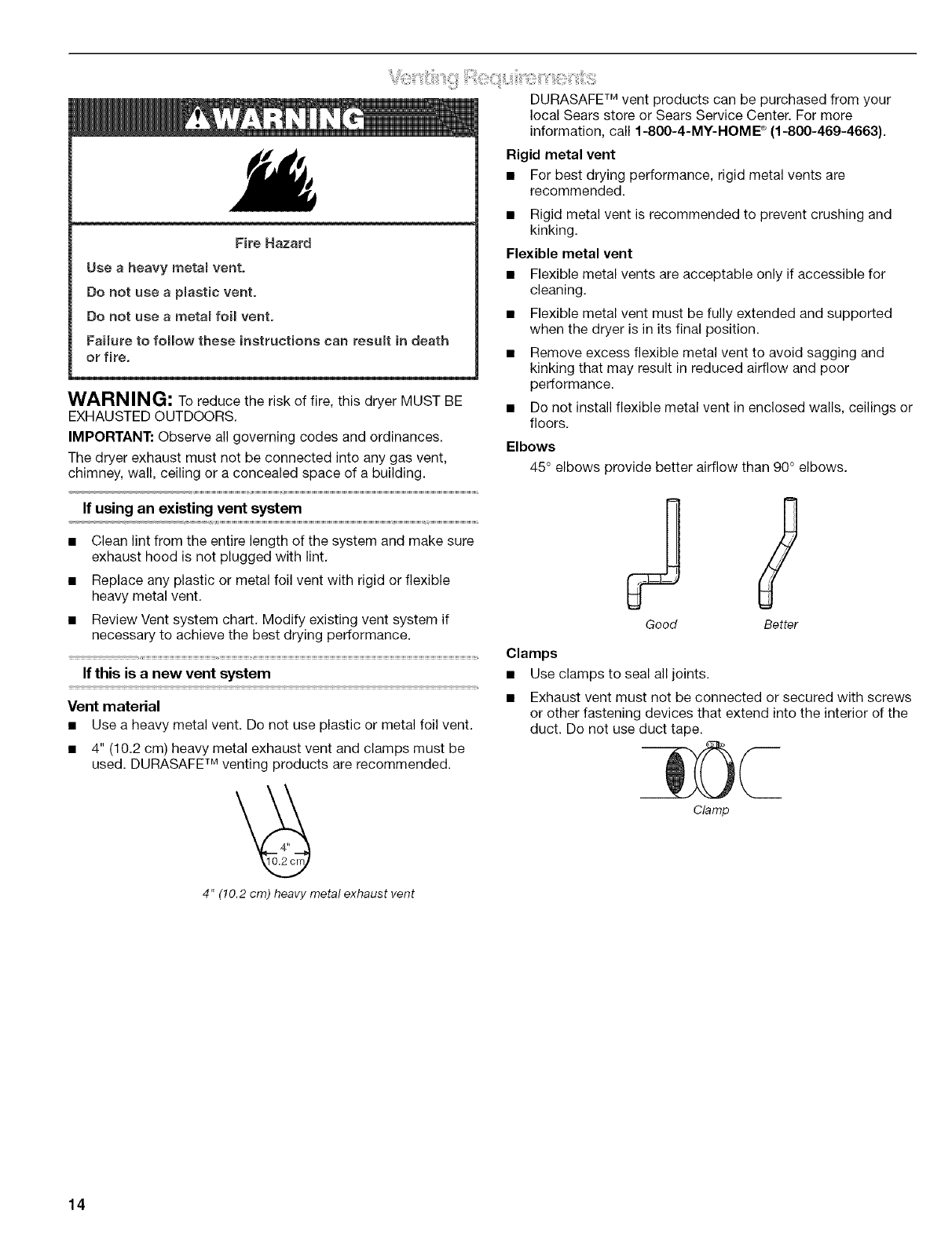
DURASAFE TM vent products can be purchased from your
local Sears store or Sears Service Center. For more
information, call 1-800-4-M¥-I-IOME _ (1-800-469-4663).
Fire Hazard
Use a heavy metam vent.
Do not use a pmastic vent.
Do not use a metam foil vent.
Failure to follow these instructions can result in death
or fire.
WARNING: To reduce the risk of fire, this dwer MUST BE
EXHAUSTED OUTDOORS.
IMPORTANT: Observe all governing codes and ordinances.
The dwer exhaust must not be connected into any gas vent,
chimney, wall, ceiling or a concealed space of a building.
Rigid metal vent
• For best drying performance, rigid metal vents are
recommended.
• Rigid metal vent is recommended to prevent crushing and
kinking.
Flexible metal vent
• Flexible metal vents are acceptable only if accessible for
cleaning.
• Flexible metal vent must be fully extended and supported
when the dryer is in its final position.
• Remove excess flexible metal vent to avoid sagging and
kinking that may result in reduced airflow and poor
performance.
• Do not install flexible metal vent in enclosed walls, ceilings or
floors.
Elbows
45° elbows provide better airflow than 90 ° elbows.
If using an existing vent system
• Clean lint from the entire length of the system and make sure
exhaust hood is not plugged with lint.
• Replace any plastic or metal foil vent with rigid or flexible
heavy metal vent.
• Review Vent system chart. Modify existing vent system if
necessary to achieve the best drying performance.
If this is a new vent system
Vent material
• Use a heavy metal vent. Do not use plastic or metal foil vent.
• 4" (10.2 cm) heavy metal exhaust vent and clamps must be
used. DURASAFE TM venting products are recommended.
Clamps
Good Better
Use clamps to seal all joints.
Exhaust vent must not be connected or secured with screws
or other fastening devices that extend into the interior of the
duct. Do not use duct tape.
Clamp
4" (10.2 cm) heavy metal exhaust vent
14
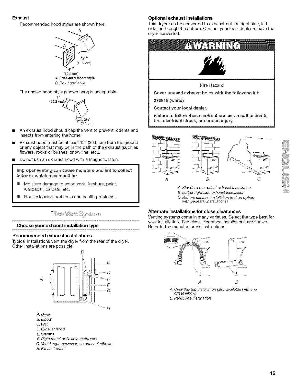
Exhaust
Recommended hood styles are shown here.
_ (1_4"!m)
(I0_2cm)
A. Louvered hood style
B. Box hood style
The angled hood style (shown here) is acceptable.
(6.4 cm)
An exhaust hood should cap the vent to prevent rodents and
insects from entering the home.
Exhaust hood must be at least 12" (30.5 cm) from the ground
or any object that may be in the path of the exhaust (such as
flowers, rocks or bushes, snow line, etc.).
•Do not use an exhaust hood with a magnetic latch.
_mproper venting can cause moisture and mintto collect
indoors, which may resumt in:
[] Moisture damage to woodwork, furniture, paint,
wallpaper, carpets, etc=
[] Housecleaning problems and health problems.
Choose your exhaust installation type
Recommended exhaust installations
Typical installations vent the dryer from the rear of the dryer.
Other installations are possible.
B
A
C
..............................F
.....................................e
Optional exhaust installations
This dryer can be converted to exhaust out the right side, left
side, or through the bottom. Contact your local dealer to have the
dryer converted.
Fire Hazard
Cover unused exhaust ho_es with the following kit:
279818 (white}
Contact your Ioca_ dealer.
Failure to follow these instructions can result in death,
fire, eiectrica_ shock, or serious injury.
A
q-
B
A. Standard rear offset exhaust installation
B. Left or right side exhaust installation
C. Bottom exhaust installation (not an option
with pedestal installations)
Alternate installations for close clearances
Venting systems come in many varieties. Select the type best for
your installation. Two close-clearance installations are shown.
Refer to the manufacturer's instructions.
=
A B
A. Over-the-top installation (also available with one
offset elbow)
B. Periscope installation
A. Dryer
B. Elbow
C. Wall
D. Exhaust hood
E. Clamps
F. Rigid metal or flexible metal vent
G. Vent length necessary to connect elbows
H. Exhaust outlet
15
NOTE: The following kits for close clearance alternate
installations are available for purchase. For further information,
please call 1-800-4-MY-HOME ®(1-800-469-4663).
• Over-the-Top Installation:
Part Number 26-49900
• Periscope Installation (For use with dryer vent to wall vent
mismatch):
Part Number 26-49901 - Less than 5" (12.7 cm) mismatch
Part Number 26-49908 - 5" (12.7 cm) to 18" (45.72 cm)
mismatch
Part Number 26-49904 - 18" (45.72 cm) to 29" (73.66 cm)
mismatch
Part Number 26-49905 - 29" (73.66 cm) to 50" (127 cm)
mismatch
Special provisions for mobile home installations
The exhaust vent must be securely fastened to a noncombustible
portion of the mobile home structure and must not terminate
beneath the mobile home. Terminate the exhaust vent outside.
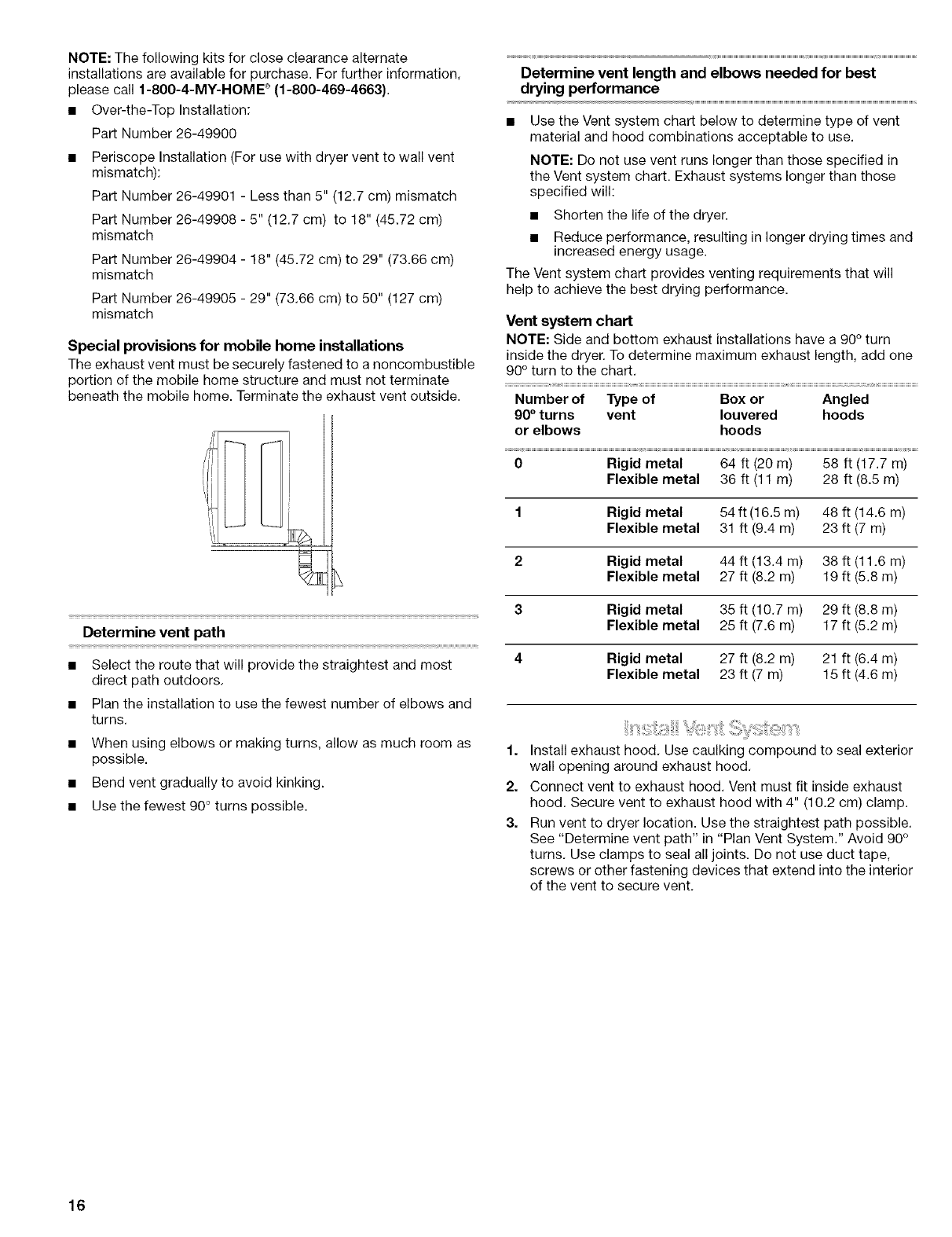
Determine vent path
• Select the route that will provide the straightest and most
direct path outdoors.
• Plan the installation to use the fewest number of elbows and
turns.
• When using elbows or making turns, allow as much room as
possible.
• Bend vent gradually to avoid kinking.
• Use the fewest 90 ° turns possible.
Determine vent length and elbows needed for best
drying performance
• Use the Vent system chart below to determine type of vent
material and hood combinations acceptable to use.
NOTE: Do not use vent runs longer than those specified in
the Vent system chart. Exhaust systems longer than those
specified will:
• Shorten the life of the dryer.
• Reduce performance, resulting in longer drying times and
increased energy usage.
The Vent system chart provides venting requirements that will
help to achieve the best drying performance.
Vent system chart
NOTE: Side and bottom exhaust installations have a 90° turn
inside the dryer. To determine maximum exhaust length, add one
90° turn to the chart.
Number of Type of Box or Angled
90°turns vent leuvered hoods
or elbows hoods
0 Rigid metal 64 ft (20 m) 58 ft (17.7 m)
Flexible metal 36 ft (11 m) 28 ft (8.5 m)
1 Rigid metal 54 ft (16.5 m) 48 ft (14.6 m)
Flexible metal 31 ft (9.4 m) 23 ft (7 m)
2 Rigid metal 44 ft (13.4 m) 38 ft (11.6 m)
Flexible metal 27 ft (8.2 m) 19 ft (5.8 m)
3 Rigid metal 35 ft (10.7 m) 29 ft (8.8 m)
Flexible metal 25 ft (7.6 m) 17 ft (5.2 m)
4 Rigid metal 27 ft (8.2 m) 21 ft (6.4 m)
Flexible metal 23 ft (7 m) 15 ft (4.6 m)
1. Install exhaust hood. Use caulking compound to seal exterior
wall opening around exhaust hood.
2. Connect vent to exhaust hood. Vent must fit inside exhaust
hood. Secure vent to exhaust hood with 4" (10.2 cm) clamp.
3. Run vent to dryer location. Use the straightest path possible.
See "Determine vent path" in "Plan Vent System." Avoid 90 °
turns. Use clamps to seal all joints. Do not use duct tape,
screws or other fastening devices that extend into the interior
of the vent to secure vent.
16
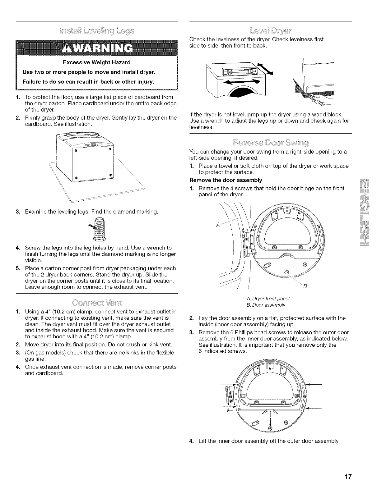
Check the levelness of the dryer. Check levelness first
side to side, then front to back.
1. To protect the floor, use a large flat piece of cardboard from
the dryer carton. Place cardboard under the entire back edge
of the dryer.
2. Firmly grasp the body of the dryer. Gently lay the dryer on the
cardboard. See illustration.
_\\\\\\\\\\\\\\\\
Examine the leveling legs. Find the diamond marking.
4. Screw the legs into the leg holes by hand. Use a wrench to
finish turning the legs until the diamond marking is no longer
visible.
5. Place a carton corner post from dryer packaging under each
of the 2 dryer back corners. Stand the dryer up. Slide the
dryer on the corner posts until it is close to its final location.
Leave enough room to connect the exhaust vent.
1. Using a 4" (10.2 cm) clamp, connect vent to exhaust outlet in
dryer. If connecting to existing vent, make sure the vent is
clean. The dryer vent must fit over the dryer exhaust outlet
and inside the exhaust hood. Make sure the vent is secured
to exhaust hood with a 4" (10.2 cm) clamp.
2. Move dryer into its final position. Do not crush or kink vent.
3. (On gas models) check that there are no kinks in the flexible
gas line.
4. Once exhaust vent connection is made, remove corner posts
and cardboard.
If the dryer is not level, prop up the dryer using a wood block.
Use a wrench to adjust the legs up or down and check again for
levelness.
You can change your door swing from a right-side opening to a
left-side opening, if desired.
1. Place a towel or soft cloth on top of the dryer or work space
to protect the surface.
Remove the door assembly
1. Remove the 4 screws that hold the door hinge on the front
panel of the dryer.
2=
3.
A. Dryer front panel
B. Door assembly
Lay the door assembly on a flat, protected surface with the
inside (inner door assembly) facing up.
Remove the 6 Phillips head screws to release the outer door
assembly from the inner door assembly, as indicated below.
See illustration. It is important that you remove only the
6 indicated screws.
4. Lift the inner door assembly off the outer door assembly.
17
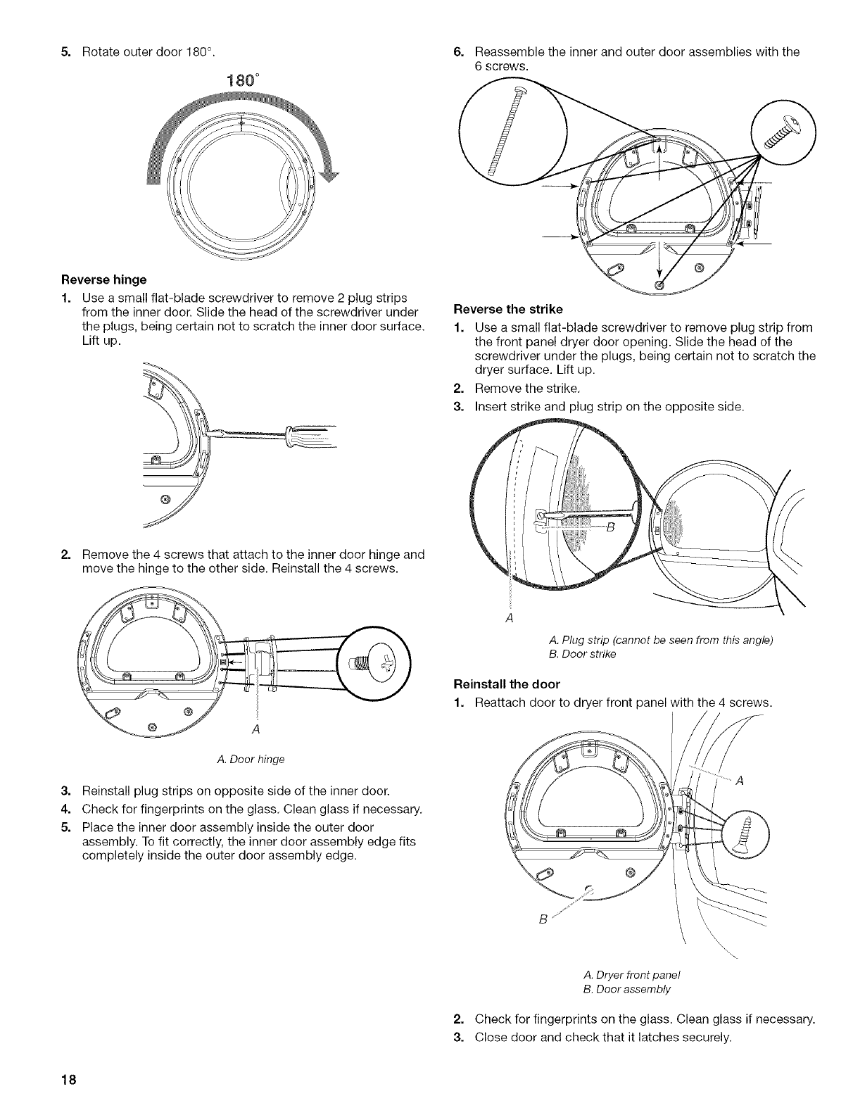
5. Rotate outer door 180 °.
180 °
6. Reassemble the inner and outer door assemblies with the
6 screws.
Reverse hinge
1. Use a small flat-blade screwdriver to remove 2 plug strips
from the inner door. Slide the head of the screwdriver under
the plugs, being certain not to scratch the inner door surface.
Lift up.
Reverse the strike
1. Use a small flat-blade screwdriver to remove plug strip from
the front panel dryer door opening. Slide the head of the
screwdriver under the plugs, being certain not to scratch the
dryer surface. Lift up.
2. Remove the strike.
3. Insert strike and plug strip on the opposite side.
@
2. Remove the 4 screws that attach to the inner door hinge and
move the hinge to the other side. Reinstall the 4 screws.
A
A. Plug strip (cannot be seen from this angle)
B. Door strike
Reinstall the door
1. Reattach door to dryer front panel with the 4 screws.
A. Door hinge
3. Reinstall plug strips on opposite side of the inner door.
4. Check for fingerprints on the glass. Clean glass if necessary.
5. Place the inner door assembly inside the outer door
assembly. To fit correctly, the inner door assembly edge fits
completely inside the outer door assembly edge.
@
A. Dryer front panel
B. Door assembly
\
\\\\\\
2. Check for fingerprints on the glass. Clean glass if necessary.
3. Close door and check that it latches securely.
18
1. Check that all parts are now installed. If there is an extra part,
go back through the steps to see which step was skipped.
2. Check that you have all of your tools.
3. Dispose of/mcycle all packaging materials.
4. Check the dryer's final location. Be sure the vent is not
crushed or kinked.
5. Check that the dryer is level. See "Level Dryer."
6. For power supply cord installation, plug into an outlet. For
direct wire installation, turn on power.
7. Remove any protective film or tape remaining on the dryer.
8. Read "Dryer Use."
9. Wipe the dryer drum interior thoroughly with a damp cloth to
remove any dust.
10. Select a Timed Dry heated cycle, and start the dryer. Do not
select the Air Only modifier.
If the dryer will not start, check the following:
• Controls are set in a running or "On" position.
• Start button has been pushed firmly.
• Dryer is plugged into an outlet and/or electrical supply
is on.
• Household fuse is intact and tight, or circuit breaker has
not tripped.
• Dryer door is closed.
11. When the dryer has been running for 5 minutes, open the
dryer door and feel for heat. If you feel heat, cancel cycle and
close door.
If you do not feel heat, turn off the dryer and check the
following:
• There may be 2 fuses or circuit breakers for the dryer.
Check to make sure both fuses are intact and tight, or
that both circuit breakers have not tripped. If there is still
no heat, contact a qualified technician.
NOTE: You may notice a burning odor when the dryer is first
heated. This odor is common when the heating element is first
used. The odor will go away.
19
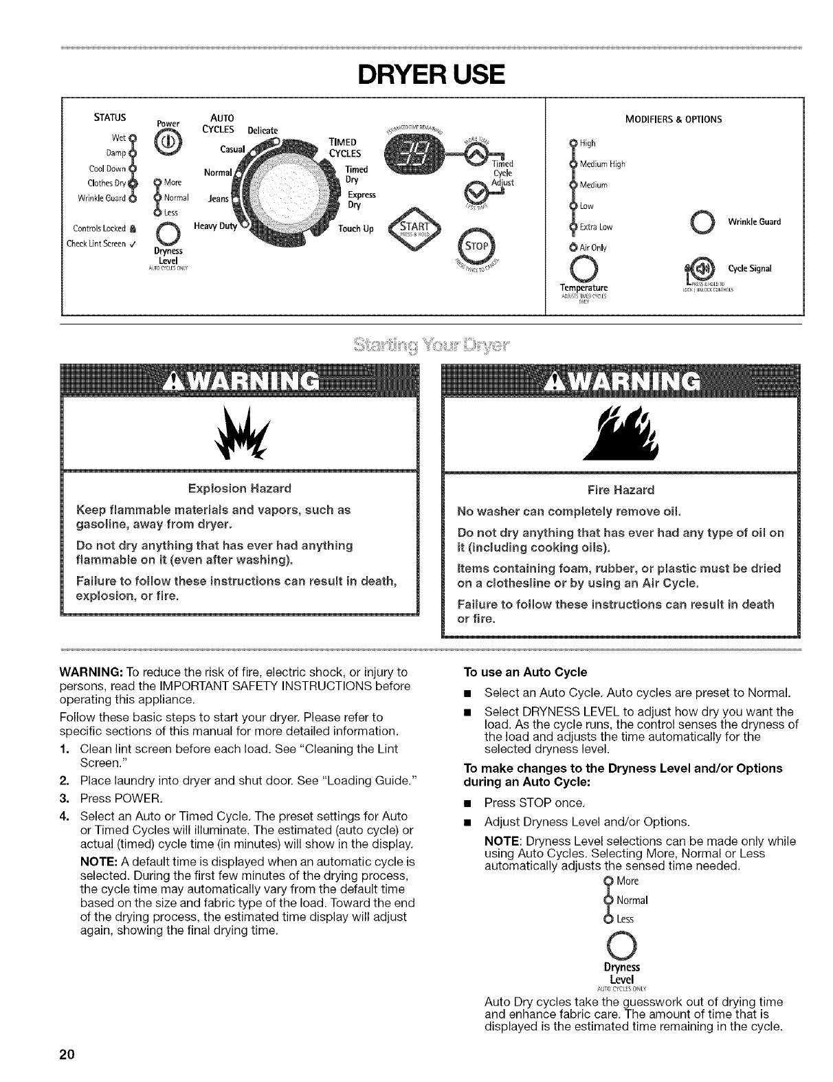
DRYER USE
MODIFIERS & OPTIONS
STATUS Power
Wet
pomp?
Cool Down (jL_
Clothes Dry _ _ More
WrinkleGuard O _ Normal
O Less
ControlsLocked _
%J
Cheek Lint Screen _/ Dryness
Level
_Jlo CYCLESONE"
AUTO
CYCLES Delicate
TIMED
Casual CYCLES
Normal Timed
Dry
Jeans Express
Dry
Touch Up
Cycle
I igh
Medium High
Medium
Low
_ _xtra Low
_) Air Only
©
Temperature
ADSTSIS_ C_CES
U_L¥
Wrinkle Guard
CS/cle Signal
LOCKiUNLOCKCONIR_L_
Explosion Hazard
Keep flammabme materiams and vapors, such as
gasoline, away from dryer,
Do not dry anything that has ever had anything
fiammabme on it (even after washing),
Failure to follow these instructions can resumt in death,
expmosion, or fire,
Fire Hazard
No washer can completely remove oil
Do not dry anything that has ever had any type of oH on
it (including cooking oils),
Items containing foam, rubber, or plastic must be dried
on a cmothesmine or by using an Air Cycme,
Faiiure to follow these instructions can result in death
or fire,
WARNING: To reduce the risk of fire, electric shock, or injury to
persons, read the IMPORTANT SAFETY INSTRUCTIONS before
operating this appliance.
Follow these basic steps to start your dryer. Please refer to
specific sections of this manual for more detailed information.
1. Clean lint screen before each load. See "Cleaning the Lint
Screen."
2. Place laundry into dryer and shut door. See "Loading Guide."
3. Press POWER.
4. Select an Auto or Timed Cycle, The preset settings for Auto
or Timed Cycles will illuminate. The estimated (auto cycle) or
actual (timed) cycle time (in minutes) will show in the display,
NOTE: A default time is displayed when an automatic cycle is
selected. During the first few minutes of the drying process,
the cycle time may automatically vary from the default time
based on the size and fabric type of the load. Toward the end
of the drying process, the estimated time display will adjust
again, showing the final drying time.
To use an Auto Cycle
• Select an Auto Cycle. Auto cycles are preset to Normal.
• Select DRYNESS LEVEL to adjust how dry you want the
load. As the cycle runs, the control senses the dryness of
the load and adjusts the time automatically for the
selected dryness level.
To make changes to the Dryness Level and/or Options
during an Auto Cycle:
•Press STOP once.
Adjust Dryness Level and/or Options.
NOTE: Dryness Level selections can be made only while
using Auto Cycles. Selecting More, Normal or Less
automatically adjusts the sensed time needed.
More
Normal
Less
©
Dryness
Level
AUTO CYCL[S ONLY
Auto Dry cycles take the guesswork out of drying time
and enhance fabric care. The amount of time that is
displayed is the estimated time remaining in the cycle.
20
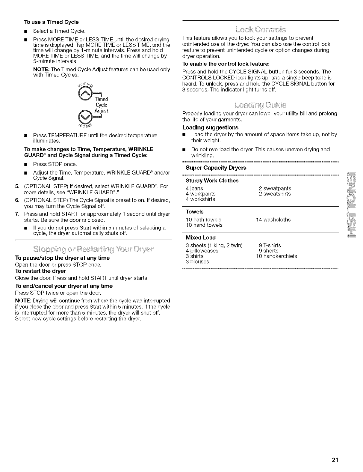
To use a Timed Cycle
Select a Timed Cycle.
Press MORE TIME or LESS TIME until the desired drying
time is displayed. Tap MORE TIME or LESS TIME, and the
time will change by 1-minute intervals. Press and hold
MORE TIME or LESS TIME, and the time will change by
5-minute intervals.
NOTE: The Timed Cycle Adjust features can be used only
with Timed Cycles.
Cycle
5=
6.
7.
• Press TEMPERATURE until the desired temperature
illuminates.
To make changes to Time, Temperature, WRINKLE
GUARD ®and Cycle Signal during a Timed Cycle:
• Press STOP once.
• Adjust the Time, Temperature, WRINKLE GUARD _ and/or
Cycle Signal.
(OPTIONAL STEP) If desired, select WRINKLE GUARD_L For
more details, see "WRINKLE GUARD_C'
(OPTIONAL STEP) The Cycle Signal is preset to on. If desired,
you may turn the Cycle Signal off.
Press and hold START for approximately 1 second until dryer
starts. Be sure the door is closed.
• If you do not press Start within 5 minutes of selecting a
cycle, the dryer automatically shuts off.
To pause/stop the dryer at any time
Open the door or press STOP once.
To restart the dryer
Close the door. Press and hold START until dryer starts.
To end/cancel your dryer at any time
Press STOP twice or open the door.
NOTE: Drying will continue from where the cycle was interrupted
if you close the door and press Start within 5 minutes. If the cycle
is interrupted for more than 5 minutes, the dryer will shut off.
Select new cycle settings before restarting the dryer.
This feature allows you to lock your settings to prevent
unintended use of the dryer. You can also use the control lock
feature to prevent unintended cycle or option changes during
dryer operation.
To enable the control lock feature:
Press and hold the CYCLE SIGNAL button for 3 seconds. The
CONTROLS LOCKED icon lights up, and a single beep tone is
heard. To unlock, press and hold the CYCLE SIGNAL button for
3 seconds. The indicator light turns off.
Properly loading your dryer can lower your utility bill and prolong
the life of your garments.
Loading suggestions
• Load the dryer by the amount of space items take up, not by
their weight.
• Do not overload the dryer. This causes uneven drying and
wrinkling.
Super Capacity Dryers
Sturdy Work Clothes
4 jeans 2 sweatpants
4 workpants 2 sweatshirts
4 workshirts
Towels
10 bath towels
10 hand towels 14 washcloths
Mixed Load
3 sheets (1 king, 2 twin) 9 T-shirts
4 pillowcases 9 shorts
3 shirts 10 handkerchiefs
3 blouses
21
Select the correct cycle and dryness level or temperature for your
load. If an Auto Cycle is running, the display shows the estimated
cycle time, which is determined by your dryer automatically
sensing the dryness level of your load. If a Timed Cycle is
running, the display shows the exact number of minutes
remaining in the cycle.
Cool Down tumbles the load without heat during the last few
minutes of all cycles. Cool Down makes the loads easier to
handle and reduces wrinkling. The length of the Cool Down
depends on the load size and dryness level.
Drying tips
• Follow care label directions when they are available.
• If desired, add a fabric softener sheet. Follow package
instructions.
• To reduce wrinkling, remove the load from the dryer as soon
as tumbling stops. This is especially important for permanent
press, knits, and synthetic fabrics.
• Avoid drying heavy work clothes together with lighter fabrics.
This could cause overdrying of lighter fabrics and lead to
increased shrinkage or wrinkling.
Cycle tips
• Dry most loads using the preset cycle settings.
• Refer to the Auto Cycles or Timed Cycles Preset Settings
chart (in the "Cycles" section) for a guide to drying various
loads.
• Drying temperature and Dryness Level are preset when
you choose an Auto Cycle. You can select a different
dryness level, depending on your load, by pressing
Dryness Level and choosing More or Less.
NOTE: You cannot use the Timed Cycle Adjust and you
cannot modify temperature with the Auto Dry cycles.
• If you wish to adjust the cycle length of a Timed Cycle,
press More Time or Less Time. Adjust the temperature of
a Timed Cycle by pressing TEMPERATURE until the
desired temperature is selected.
NOTE: You cannot use the Dryness Level with Timed
Cycles.
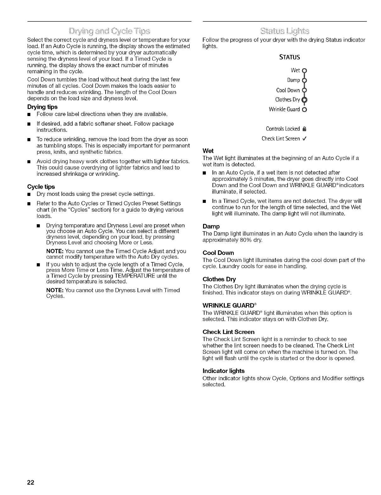
Follow the progress of your dryer with the drying Status indicator
lights.
STATUS
wet
Damp?
Cool Down?
ClothesDry9
Wrinkle Guard0
ControlsLocked
CheckLintScreen V
Wet
The Wet light illuminates at the beginning of an Auto Cycle if a
wet item is detected.
• In an Auto Cycle, if a wet item is not detected after
approximately 5 minutes, the dryer goes directly into Cool
Down and the Cool Down and WRINKLE GUARD_qndicators
illuminate, if selected.
• In a Timed Cycle, wet items are not detected. The dryer will
continue to run for the length of time selected, and the Wet
light will illuminate. The damp light will not illuminate.
Damp
The Damp light illuminates in an Auto Cycle when the laundry is
approximately 80% dry.
Cool Down
The Cool Down light illuminates during the cool down part of the
cycle. Laundry cools for ease in handling.
Clothes Dry
The Clothes Dry light illuminates when the drying cycle is
finished. This indicator stays on during WRINKLE GUARD ®.
WRINKLE GUARD _
The WRINKLE GUARD ®light illuminates when this option is
selected. This indicator stays on with Clothes Dry.
Check Lint Screen
The Check Lint Screen light is a reminder to check to see
whether the lint screen needs to be cleaned. The Check Lint
Screen light will come on when the machine is turned on. The
light will flash until the cycle is started or the door is opened.
Indicator lights
Other indicator lights show Cycle, Options and Modifier settings
selected.
22
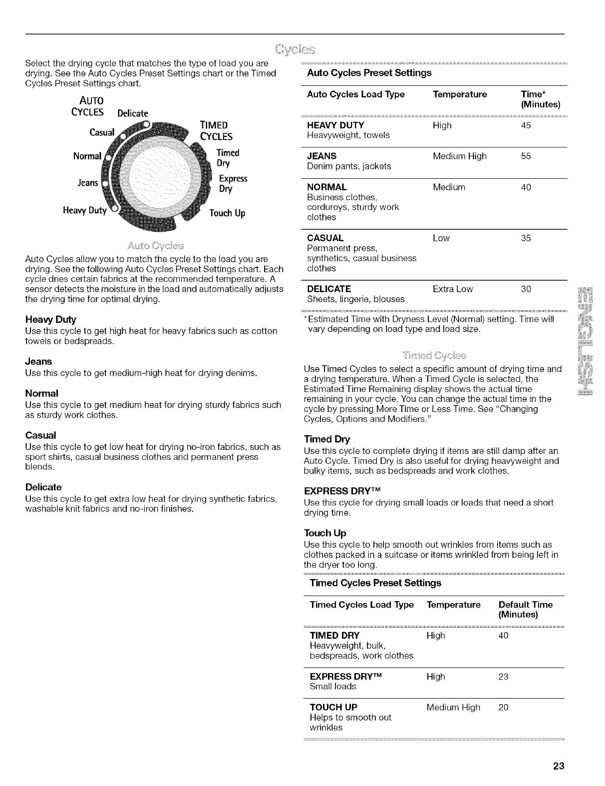
Select the drying cycle that matches the type of load you are
drying. See the Auto Cycles Preset Settings chart or the Timed
Cycles Preset Settings chart.
AUTO
CYCLES Delicate
TIMED
Casual CYCLES
Normal Timed
Dry
Jeans i Express
Dry
Heavy Duty Touch Up
Auto Cycles allow you to match the cycle to the load you are
drying. See the following Auto Cycles Preset Settings chart. Each
cycle dries certain fabrics at the recommended temperature. A
sensor detects the moisture in the load and automatically adjusts
the drying time for optimal drying.
Heavy Duty
Use this cycle to get high heat for heavy fabrics such as cotton
towels or bedspreads.
Jeans
Use this cycle to get medium-high heat for drying denims.
Normal
Use this cycle to get medium heat for drying sturdy fabrics such
as sturdy work clothes.
Casual
Use this cycle to get low heat for drying no-iron fabrics, such as
sport shirts, casual business clothes and permanent press
blends.
Delicate
Use this cycle to get extra low heat for drying synthetic fabrics,
washable knit fabrics and no-iron finishes.
Auto Cycles Preset Settings
Auto Cycles Load Type Temperature Time*
(Minutes)
HEAVY DUTY High 45
Heavyweight, towels
JEANS Medium High 55
Denim pants, jackets
NORMAL
Business clothes,
corduroys, sturdy work
clothes
Medium 40
CASUAL
Permanent press,
synthetics, casual business
clothes
Low 35
DELICATE Extra Low 30
Sheets, lingerie, blouses
* Estimated Time with Dryness Level (Normal) setting. Time will i! i
vary depending on load type and load size.
Use Timed Cycles to select a specific amount of drying time and
a drying temperature. When a Timed Cycle is selected, the
Estimated Time Remaining display shows the actual time
remaining in your cycle. You can change the actual time in the
cycle by pressing More Time or Less Time. See "Changing
Cycles, Options and Modifiers."
Timed Dry
Use this cycle to complete drying if items are still damp after an
Auto Cycle. Timed Dry is also useful for drying heavyweight and
bulky items, such as bedspreads and work clothes.
EXPRESS DRY TM
Use this cycle for drying small loads or loads that need a short
drying time.
Touch Up
Use this cycle to help smooth out wrinkles from items such as
clothes packed in a suitcase or items wrinkled from being left in
the dryer too long.
Timed Cycles Preset Settings
Timed Cycles Load Type Temperature Default Time
(Minutes)
TIMED DRY High 40
Heavyweight, bulk,
bedspreads, work clothes
EXPRESS DRY TM High 23
Small loads
TOUCH UP Medium High 20
Helps to smooth out
wrinkles
23
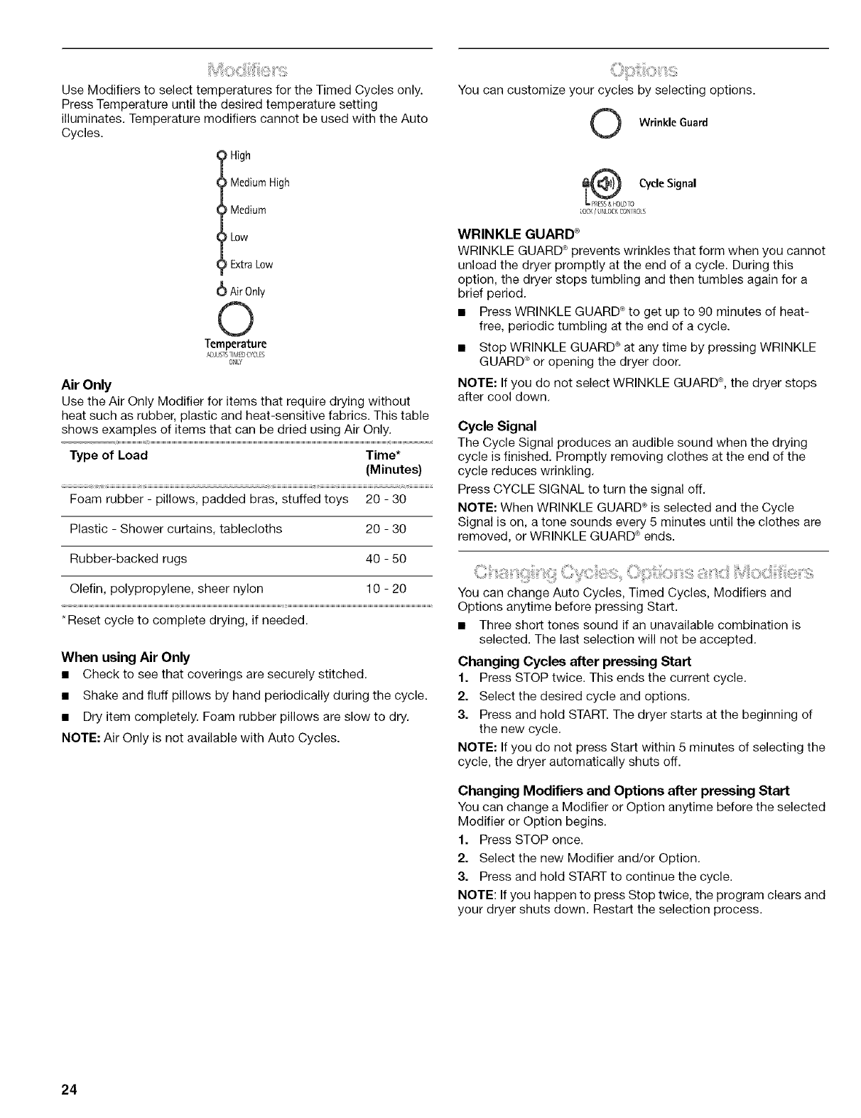
Use Modifiers to select temperatures for the Timed Cycles only.
Press Temperature until the desired temperature setting
illuminates. Temperature modifiers cannot be used with the Auto
Cycles.
) High
Medium High
Medium
Low
Extra Low
Air 0nly
Temperature
ADJUSTSTIMED(YCLES
ONLY
Air Only
Use the Air Only Modifier for items that require dwing without
heat such as rubber, plastic and heat-sensitive fabrics. This table
shows examples of items that can be dried using Air Only.
Type of Load Time*
(Minutes)
Foam rubber - pillows, padded bras, stuffed toys 20 - 30
Plastic - Shower curtains, tablecloths 20 - 30
Rubber-backed rugs 40 - 50
Olefin, polypropylene, sheer nylon 10 - 20
*Reset cycle to complete drying, if needed.
When using Air Only
• Check to see that coverings are securely stitched.
• Shake and fluff pillows by hand periodically during the cycle.
• Dry item completely. Foam rubber pillows are slow to dry.
NOTE: Air Only is not available with Auto Cycles.
You can customize your cycles by selecting options.
OWrinkleGuard
_LDTO CycleSignal
LOCK/ UNLOCKCONIROLS
WRINKLE GUARD _
WRINKLE GUARD _ prevents wrinkles that form when you cannot
unload the dryer promptly at the end of a cycle. During this
option, the dryer stops tumbling and then tumbles again for a
brief period.
• Press WRINKLE GUARD _ to get up to 90 minutes of heat-
free, periodic tumbling at the end of a cycle.
• Stop WRINKLE GUARD ®at any time by pressing WRINKLE
GUARD _ or opening the dryer door.
NOTE: If you do not select WRINKLE GUARD ®, the dryer stops
after cool down.
Cycle Signal
The Cycle Signal produces an audible sound when the drying
cycle is finished. Promptly removing clothes at the end of the
cycle reduces wrinkling.
Press CYCLE SIGNAL to turn the signal off.
NOTE: When WRINKLE GUARD _ is selected and the Cycle
Signal is on, a tone sounds every 5 minutes until the clothes are
removed, or WRINKLE GUARD _ ends.
You can change Auto Cycles, Timed Cycles, Modifiers and
Options anytime before pressing Start.
• Three short tones sound if an unavailable combination is
selected. The last selection will not be accepted.
Changing Cycles after pressing Start
1. Press STOP twice. This ends the current cycle.
2. Select the desired cycle and options.
3. Press and hold START. The dryer starts at the beginning of
the new cycle.
NOTE: If you do not press Start within 5 minutes of selecting the
cycle, the dryer automatically shuts off.
Changing Modifiers and Options after pressing Start
You can change a Modifier or Option anytime before the selected
Modifier or Option begins.
1. Press STOP once.
2. Select the new Modifier and/or Option.
3. Press and hold START to continue the cycle.
NOTE: If you happen to press Stop twice, the program clears and
your dryer shuts down. Restart the selection process.
24
! Z iIViiB: !L£:!i:il ili3iG@ ii ¸¸¸¸
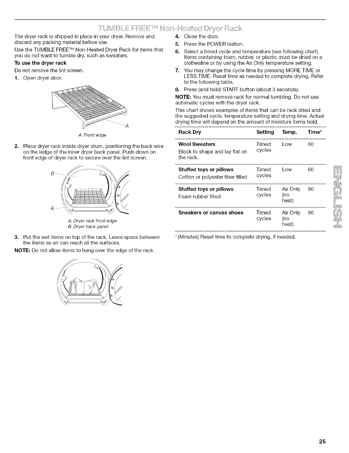
The dryer rack is shipped in place in your dryer. Remove and
discard any packing material before use.
Use the TUMBLE FREE TM Non-Heated Dryer Rack for items that
you do not want to tumble dry, such as sweaters.
To use the dryer rack
Do not remove the lint screen.
1. Open dryer door.
A. Front edge
2. Place dryer rack inside dryer drum, positioning the back wire
on the ledge of the inner dryer back panel. Push down on
front edge of dryer rack to secure over the lint screen.
4. Close the door.
5. Press the POWER button.
6. Select a timed cycle and temperature (see following chart).
Items containing foam, rubber, or plastic must be dried on a
clothesline or by using the Air Only temperature setting.
7. You may change the cycle time by pressing MORE TIME or
LESS TIME. Reset time as needed to complete drying. Refer
to the following table.
8. Press (and hold) START button (about 3 seconds).
NOTE: You must remove rack for normal tumbling. Do not use
automatic cycles with the dryer rack.
This chart shows examples of items that can be rack dried and
the suggested cycle, temperature setting and drying time. Actual
drying time will depend on the amount of moisture items hold.
Rack Dry Setting Temp. Time*
Wool Sweaters Timed Low 60
Block to shape and lay flat on cycles
the rack.
A. Dryer rack front edge
B. Dryer back panel
Put the wet items on top of the rack. Leave space between
the items so air can reach all the surfaces.
Stuffed toys or pillows Timed Low 60
Cotton or polyester fiber filled cycles
Stuffed toys or pillows Timed Air Only 90
Foam rubber filled cycles (no
heat)
Sneakers or canvas shoes Timed Air Only 90
cycles (no
heat)
*(Minutes) Reset time to complete drying, if needed.
NOTE: Do not allow items to hang over the edge of the rack.
25
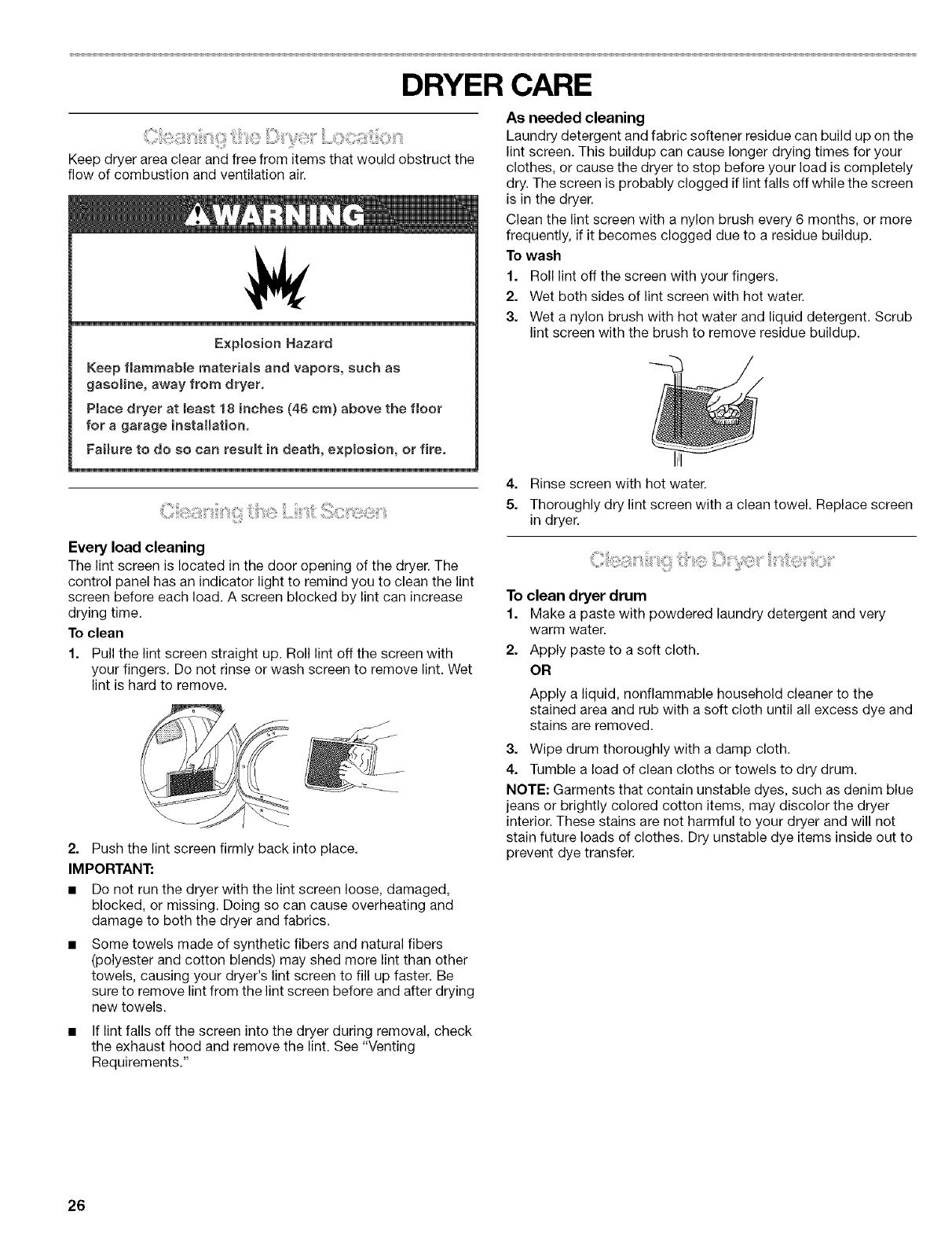
DRYER CARE
Ciii_i_!_iiii_;ii_i_iii_ii_i!!iiii__i_i!::_!_!i!:!_iiiiiiiii:i_i?li_;i!?_ii¸¸¸¸¸Loo_;_i!!_iiiiiii:ii_iio_ii_i
Keep dryer area clear and free from items that would obstruct the
flow of combustion and ventilation air.
Explosion Hazard
Keep flammable materials and vapors, such as
gasomine, away from dryer.
Place dryer at least 18 inches (46 cm) above the floor
for a garage installation.
Faimure to do so can resumt in death, explosion, or fire.
Every load cleaning
The lint screen is located in the door opening of the dryer. The
control panel has an indicator light to remind you to clean the lint
screen before each load. A screen blocked by lint can increase
drying time.
To clean
1. Pull the lint screen straight up. Roll lint off the screen with
your fingers. Do not rinse or wash screen to remove lint. Wet
lint is hard to remove.
2. Push the lint screen firmly back into place.
IMPORTANT:
• Do not run the dryer with the lint screen loose, damaged,
blocked, or missing. Doing so can cause overheating and
damage to both the dryer and fabrics.
Some towels made of synthetic fibers and natural fibers
(polyester and cotton blends) may shed more lint than other
towels, causing your dryer's lint screen to fill up faster. Be
sure to remove lint from the lint screen before and after drying
new towels.
If lint falls off the screen into the dryer during removal, check
the exhaust hood and remove the lint. See "Venting
Requirements."
As needed cleaning
Laundry detergent and fabric softener residue can build up on the
lint screen. This buildup can cause longer drying times for your
clothes, or cause the dryer to stop before your load is completely
dry. The screen is probably clogged if lint falls off while the screen
is in the dryer.
Clean the lint screen with a nylon brush every 6 months, or more
frequently, if it becomes clogged due to a residue buildup.
To wash
1. Roll lint off the screen with your fingers.
2. Wet both sides of lint screen with hot water.
3. Wet a nylon brush with hot water and liquid detergent. Scrub
lint screen with the brush to remove residue buildup.
4. Rinse screen with hot water.
5. Thoroughly dry lint screen with a clean towel. Replace screen
in dryer.
To clean dryer drum
1. Make a paste with powdered laundry detergent and very
warm water.
2. Apply paste to a soft cloth.
OR
Apply a liquid, nonflammable household cleaner to the
stained area and rub with a soft cloth until all excess dye and
stains are removed.
3. Wipe drum thoroughly with a damp cloth.
4. Tumble a load of clean cloths or towels to dry drum.
NOTE: Garments that contain unstable dyes, such as denim blue
jeans or brightly colored cotton items, may discolor the dryer
interior. These stains are not harmful to your dryer and will not
stain future loads of clothes. Dry unstable dye items inside out to
prevent dye transfer.
26
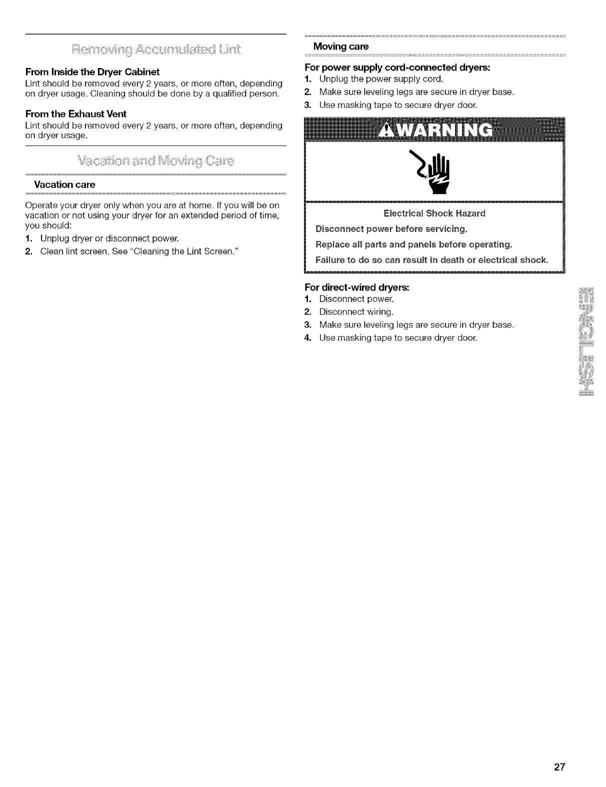
From Inside the Dryer Cabinet
Lint should be removed every 2 years, or more often, depending
on dryer usage, Cleaning should be done by a qualified person.
From the Exhaust Vent
Lint should be removed every 2 years, or more often, depending
on dryer usage.
Vacation care
Operate your dryer only when you are at home. If you will be on
vacation or not using your dryer for an extended period of time,
you should:
1. Unplug dryer or disconnect power.
2. Clean lint screen. See "Cleaning the Lint Screen,"
Moving cars
For power supply cord-connected dryers:
1. Unplug the power supply cord.
2. Make sure leveling legs are secure in dryer base,
3. Use masking tape to secure dryer door,
Electrical Shock Hazard
Disconnect power before servicing,
Replace all parts and panele before operating.
Failure to do so can result in death or electrical shock,
For direct-wirsd dryers:
1. Disconnect power.
2. Disconnect wiring.
3. Make sure leveling legs are secure in dryer base,
4. Use masking tape to secure dryer door,
27
TROUBLESHOOTING
First try the solutions suggested here and possibly avoid the cost of a service call...
Dryer will not run
Has a household fuse blown, or has a circuit breaker
tripped?
There may be 2 fuses or circuit breakers for the dryer. Check
to make sure both fuses are intact and tight, or that both
circuit breakers have not tripped. Replace the fuse or reset
the circuit breaker. If the problem continues, call an
electrician.
Is the correct power supply available?
Electric dryers require 240-volt power supply. Check with a
qualified electrician.
Was a regular fuse used?
Use a time-delay fuse.
Is the dryer door firmly closed?
Was the Start button firmly pressed?
Press and hold for 1 second.
No heat
Has a household fuse blown, or has a circuit breaker
tripped?
The drum may be turning, but you may not have heat. Electric
dryers use 2 fuses or circuit breakers. Replace the fuse or
reset the circuit breaker. If the problem continues, call an
electrician.
Unusual sounds
•Has the dryer had a period of non-use?
If the dryer hasn't been used for a while, there may be a
thumping sound during the first few minutes of operation.
is acoin, button, or paper clip caught between the drum
and front or rear of the dryer?
Check the front and rear edges of the drum for small objects.
Clean out pockets before laundering.
Are the four legs installed, and is the dryer level front to
back and side to side?
The dryer may vibrate if not properly installed. See the
Installation Instructions.
msthe clothing knotted or balled up?
When balled up, the load will bounce, causing the dryer to
vibrate. Separate the load items and restart the dryer.
Dryer displaying code message
• "PF" (power failure), check the following:
Was the drying cycle interrupted by a power failure?
Press and hold START to restart the dryer.
•"E" Variable (El, E2, E3) service codes:
Call for service.
Clothes are not drying satisfactorily, drying times are too
long, or load is too hot
•is the lint screen clogged with lint?
Lint screen should be cleaned before each load.
Fire Hazard
Use a heavy meta_ vent.
Do not use a plastic vent.
Oo not use a metal foil vent.
Failure to follow these instructions can result in death
or fire.
Is the exhaust vent or outside exhaust hood clogged with
lint, restricting air movement?
Run the dryer for 5-10 minutes. Hold your hand under the
outside exhaust hood to check air movement. If you do not
feel air movement, clean exhaust system of lint or replace
exhaust vent with heavy metal or flexible metal vent. See the
Installation Instructions.
Are fabric softener sheets blocking the grille?
Use only one fabric softener sheet, and use it only once.
Is the exhaust vent the correct length?
Check that the exhaust vent is not too long or has too many
turns. Long venting will increase drying times. See the
Installation Instructions.
Is the exhaust vent diameter the correct size?
Use 4" (10.2 cm) diameter vent material.
28
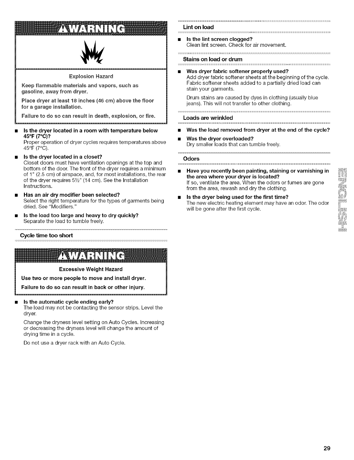
E×plosion Hazard
Keep flammable materials and vapors, such as
gasoline, away from dryer.
Place dryer at least 18 inches (46 cm) above the floor
for a garage installation.
Failure to do so can result in death, e×plosion, or fire.
Is the dryer located in a room with temperature below
45°F (7°C)?
Proper operation of dryer cycles requires temperatures above
45°F (7°C).
Is the dryer located in a closet?
Closet doors must have ventilation openings at the top and
bottom of the door. The front of the dryer requires a minimum
of 1" (2.5 cm) of airspace, and, for most installations, the rear
of the dryer requires 51/2'' (14 cm), See the Installation
Instructions,
Has an air dry modifier been selected?
Select the right temperature for the types of garments being
dried. See "Modifiers."
Is the load too large and heavy to dry quickly?
Separate the load to tumble freely.
Cycle time too short
Excessive Weight Hazard
Use two or more people to move and install dryer.
Failure to do so can result in back or other injury.
•Is the automatic cycle ending early?
The load may not be contacting the sensor strips, Level the
dryer.
Change the dryness level setting on Auto Cycles. Increasing
or decreasing the dryness level will change the amount of
drying time in a cycle.
Do not use a dryer rack with an Auto Cycle.
Lint on load
•Is the lint screen clogged?
Clean lint screen. Check for air movement.
Stains on load or drum
•Was dryer fabric softener properly used?
Add dryer fabric softener sheets at the beginning of the cycle.
Fabric softener sheets added to a partially dried load can
stain your garments.
Drum stains are caused by dyes in clothing (usually blue
jeans). This will not transfer to other clothing.
Loads are wrinkled
•Was the load removed from dryer at the end of the cycle?
•Was the dryer overloaded?
Dry smaller loads that can tumble freely.
Odors
•Have you recently been painting, staining or varnishing in
the area where your dryer is located?
If so, ventilate the area. When the odors or fumes are gone
from the area, rewash and dry the clothing.
•Is the dryer being used for the first time?
The new electric heating element may have an odor. The odor
will be gone after the first cycle.
29

30
iNDICE
CONTRATOS DE PROTECCIC)N ................................................ 31
GARANT|A .................................................................................... 32
GARANTIA DE LA OPCION DE PEDESTAL .............................. 32
SEGURIDAD DE LA SECADORA ................................................ 33
INSTRUCCIONES DE INSTALACIC)N ......................................... 34
Herramientas y piezas ............................................................... 34
Opciones .................................................................................... 34
Requisitos de ubicaci6n ........................................................... 34
Requisitos electricos .................................................................. 36
Conexi6n electrica ..................................................................... 38
Requisitos de ventilaci6n ........................................................... 43
Planificaci6n del sistema de ventilaci6n .................................... 44
Instalaci6n del sistema de ventilaci6n ....................................... 45
Instalaci6n de las patas niveladoras .......................................... 46
Conexi6n del ducto de escape .................................................. 46
Nivelaci6n de la secadora .......................................................... 46
C6mo invertir el cierre de la puerta ........................................... 47
Complete la instalaci6n ............................................................. 48
USO DE LA SECADORA .............................................................. 49
Puesta en marcha de la secadora ............................................. 49
Detenci6n o reanudaci6n de la marcha de la secadora ........... 50
Bloquear los controles ............................................................... 50
Guia para cargar ........................................................................ 50
Sugerencias de ciclos y secado ................................................ 51
Luces de estado ........................................................................ 51
Ciclos ......................................................................................... 52
Modificadores ............................................................................ 53
Opciones .................................................................................... 53
Cambio de ciclos, opciones y modificadores ........................... 53
Estante no t@mico de la secadora TUMBLE FREF M.............. 54
CUIDADO DE LA SECADORA .................................................... 55
Limpieza del lugar donde esta la secadora ............................... 55
Limpieza del filtro de pelusa ...................................................... 55
Limpieza del interior de la secadora .......................................... 55
Eliminaci6n de pelusa acumulada ............................................. 56
Cuidado para las vacaciones y la mudanza .............................. 56
SOLUCION DE PROBLEMAS ..................................................... 57
NUMEROS DE SERVICIO .............................. CONTRAPORTADA
CONTRATOS DE
PROTECCION
Contratos Maestros de Proteccibn
iFelicitaciones per su inteligente adquisici6n! Su nuevo producto
Kenmore _ ha sido diseSado y fabricado para brindarle aSos de
funcionamiento confiable. Pero al igual que todos los productos,
puede necesitar mantenimiento preventivo o reparaci6n de vez
en cuando. Es alli donde el Contrato Maestro de Protecci6n
puede ahorrarle dinero e inconvenientes.
Adquiera un Contrato Maestro de Proteccidn hoy y prot6jase
contra molestias y gastos inesperados.
El Contrato Maestro de Proteccidn tambien ayuda a prolongar la
vida de su nuevo producto. He aqui Io que se incluye en el
Contrato:
Servicio experto por nuestros 12.000 especialistas en
reparaci6n competentes
Servicio ilimitado y gratuito para repuestos y mane de obra
en todas las reparaciones protegidas per el contrato
Garantia "sin disgustos" - reemplazo de su producto
protegido si ocurren cuatro o mas fallas del producto en el
transcurso de doce meses
Reemplazo del producto si su producto protegido no puede
ser reparado
Revisi6n Anual de Mantenimiento Preventivo a solicitud
suya - sin costo adicional
Ayuda rapida por tel_fono - asistencia per telefono a cargo
de un tecnico de Sears para productos que deban ser
reparados en su hogar, ademas de un horario de reparaci6n
conveniente
Protecci6n de sobrevoltaje contra daSos electricos debido a
fluctuaciones de electricidad
Reembolso de la renta si la reparaci6n de su producto
protegido tarda mas de Io prometido
Una vez adquirido el Contrato, tan s61o tiene que Ilamar para fijar
la visita de servicio tecnico. Usted puede Ilamar a cualquier hera,
de dfa o de noche, o fijar una visita tecnica en internet.
Sears cuenta con un equipo de mas de 12.000 especialistas en
reparaci6n competentes, quienes tienen a disposici6n mas de
4,5 millones de repuestos y accesorios de calidad. 12sees el tipo
de profesionalismo con el que usted puede contar para ayudarle
a prolongar la vida de su nuevo artefacto por muchos argos mas.
iAdquiera hoy su Contrato Maestro de Protecci6n!
Se aplican algunas limitaciones y exclusiones. Para obtener
precios einformacibn adicional, Ilame al 1-800-827-6655.
Servicio de Instalacibn de Sears
Para la instalaci6n profesional de Sears de artefactos
electrodomesticos, abridores de puertas de garaje, calentadores
de agua y otros artfculos importantes de la casa, en los EE.UU.
flame al 1-800-4-MY-HOME ®.
31
GARANTIA
GARANTJA COMPLETA DE UN AI_IO PARA
LA SECADORA HE2
Durante un a_o a partir de la fecha de compra, habiendose
instalado y operado esta secadora de acuerdo con el Manual de
uso y cuidado, la misma sera reparada libre de cargo si tuviese
defectos de material o de mane de obra.
Restriccibn de garantia
Si esta secadora es empleada para algL_notro use que no sea el
domestico familiar, esta garantia s61o tiene vigencia per 90 dias a
partir de la fecha de compra. El emplee de un ducte de escape
de plastico e de heja de metal para esta secadera anulara esta
garantfa.
Servicio de reparacibn de la garantia
Puede obtener el servicio de reparaci6n de la garantia Ilamando
al 1-800-4-MY-HOME ®.Esta garantia se aplica s61o mientras la
secadora se usa en los Estados Unidos. Esta garantia le otorga
derechos legales especfficos, yes posible que usted tenga
tambien otros derechos, los cuales varfan de un estado a otro.
Sears, Roebuck and Co.
D/817WA, Hoffman Estates, IL 60179
Registro del producto
Use el espacio a continuaci6n para anotar el nQmero complete
del modelo y de la serie, as[ como la fecha de compra. Usted
podra encontrar esta informaci6n en la etiqueta con el nQmero de
modelo y de serie, en la cavidad interna superior de la puerta de
la secadera.
Siempre que se ponga en contacto con Sears respecto a su
electrodomestico, tenga esta informaci6n a mane para facilitar la
obtenci6n de ayuda o servicio tecnico.
Nt_mero de modelo 110.
Ni3mero de serie
Fecha de compra
Guarde estas instrucciones y su comprobante de compra
para referencia futura.
GARANTiA DE LA OPCION
DE PEDESTAL
Garantia completa de un afio para partes mec&nicas
Per un aSo a partir de la fecha de compra, el proveedor reparara
o reemplazara cualquiera de sus partes mecanicas si tuviesen
defectos en el material o en la fabricaci6n. Este Pedestal debe
instalarse con esta secadora de acuerdo con las instrucciones
provistas en las Instrucciones para la instalaci6n del Pedestal.
Restriccibn de la garantia
Si se somete al pedestal a un use ajeno al domestico privado y/o
se emplea con cualquier otro producto que no este detallado en
las instrucciones de instalaci6n, esta garantia queda sin vigor.
Use el espacio a continuaci6n para anotar el nQmero complete
del modelo y de la serie, asf come la fecha de compra. Usted
podra encontrar esta informaci6n en la etiqueta con el nQmero de
medele y de serie.
Siempre que se ponga en contacto con Sears respecto a su
electrodomestice, tenga esta informaci6n a mano para facilitar la
obtenci6n de ayuda o servicio tecnico.
Nt_mero de modelo 110.
Numero de serie
Fecha de compra
Guarde estas instrucciones ysu comprobante de compra
para referencia futura.
32
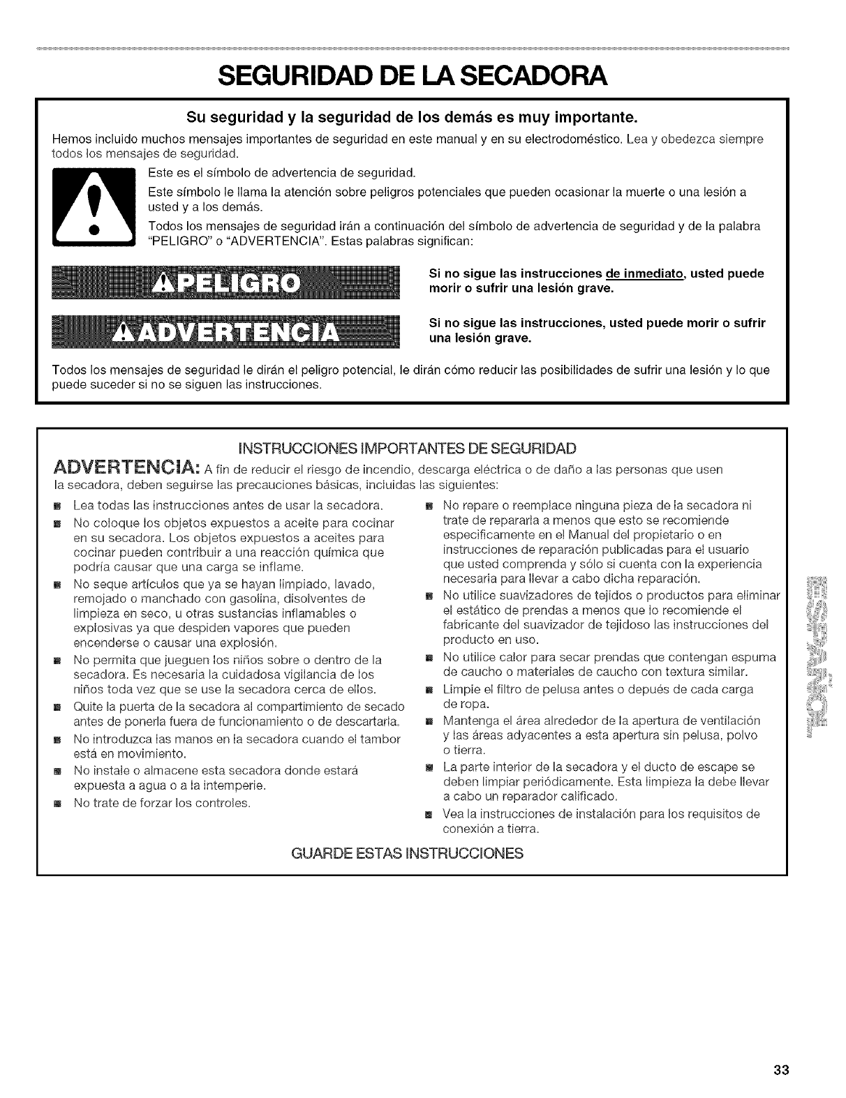
SEGURIDAD DE LA SECADORA
Su seguridad y la seguridad de los demas es muy importante.
Hemos incluido muchos mensajes importantes de seguridad en este manual yen su electrodomestico. Lea y obedezca siempre
todos los mensajes de seguridad.
Este es el sfmbolo de advertencia de seguridad.
Este sfmbolo le llama la atencion sobre peligros potenciales que pueden ocasionar la muerte o una lesidn a
usted y a los dem_.s.
Todos los mensajes de seguridad ir_.n a continuacidn del simbolo de advertencia de seguridad y de la palabra
"PELIGRO" o "ADVERTENCIA". Estas palabras significan:
Si no sigue las instrucciones de inmediato., usted puede
morir o sufrir una lesion grave.
Si no sigue las instrucciones, usted puede morir o sufrir
una lesion grave.
Todos los mensajes de seguridad le dirg_nel peligro potencial, le diran cdmo reducir las posibilidades de sufrir una lesidn y Io que
puede suceder si no se siguen las instrucciones.
INSTRUCCIONES IMPORTANTES DE SEGURIDAD
ADVERTENCIA: A fin de reducir el riesgo de incendio, descarga electdca o de da_io a Ias personas que usen
la secadora, deben seguirse las precauciones basicas, incluidas las siguientes:
_, Lea todas las instrucciones antes de usar la secadora.
_, No coloque los objetos expuestos a aceite para cocinar
en su secadora. Los objetos expuestos a aceites para
cocinar pueden contribuir a una reacci6n quimica que
podria causar que una carga se inflame.
_, No seque artfculos que ya se hayan Iimpiado, lavado,
remojado o manchado con gasotina, disolventes de
limpieza en seco, u otras sustancias infiamables o
explosivas ya que despiden vapores que pueden
encenderse o causar una explosi6n.
_, No permita que iueguen los ni¢ios sobre o dentro de la
secadora. Es necesaria la cuidadosa vigilancia de los
ninos toda vez que se use la secadora cerca de elIos.
_, Quite la puerta de la secadora al compartimiento de secado
antes de ponerla fuera de funcionamiento o de descartarla.
_, No introduzca Ias manos en Ia secadora cuando el tambor
esta en movimiento.
_, No instale o almacene esta secadora donde estara
expuesta a agua o a Ia intemperie.
_, No trate de forzar los controles.
_, No repare o reemptace ninguna pieza de Ia secadora ni
trate de repararta a menos que esto se recomiende
especificamente en et Manual del propietario o en
instrucciones de reparaci6n publicadas para el usuario
que usted comprenda y s61o si cuenta con la experiencia
necesaria para Ilevar a cabo dicha reparaci6n.
_, No utilice suavizadores de teiidos o productos para eliminar
el estatico de prendas a menos que Io recomiende el
fabricante del suavizador de teiidoso las instrucciones del
producto en uso.
_, No utilice calor para secar prendas que contengan espuma
de caucho o matedales de caucho con textura similar.
_, Limpie el filtro de pelusa antes o depues de cada carga
de ropa.
_, Mantenga el area alrededor de Ia apertura de ventilaci6n
y Ias areas adyacentes a esta apertura sin pelusa, polvo
o tierra.
m La parte interior de la secadora y et ducto de escape se
deben limpiar peri6dicamente. Esta Iimpieza Ia debe Ilevar
a cabo un reparador calificado.
m Vea la instrucciones de instalaci6n para los requisitos de
conexi6n a tierra.
GUARDE ESTAS iNSTRUCCiONES
33
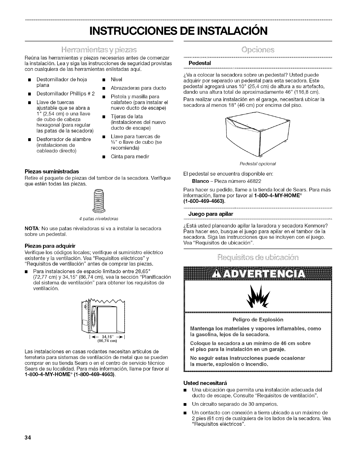
INSTRUCCIONES DE INSTALACION
Retina las herramientas y piezas necesarias antes de comenzar
la instalaci6n. Lea y siga las instrucciones de seguridad provistas
con cualquiera de las herramientas enlistadas aqui.
Destornillador de hoja •
plana •
Destornillador Phillips # 2 •
Llave de tuercas
ajustable que se abra a
1" (2,54 cm) o una Ilave
de cube de cabeza
hexagonal (para regular
las patas de la secadora)
Desforrador de alambre
(instalaciones de
cableado directo)
Nivel
Abrazaderas para ducto
Pistola y masilla para
calafateo (para instalar el
nuevo ducto de escape)
Tijeras de lata
(instalaciones del nuevo
ducto de escape)
Llave para tuercas de
1/4"o Ilave de cubo (se
recomienda)
•Cinta para medir
Piezas suministradas
Retire el paquete de piezas del tambor de la secadora. Verifique
que esten todas las piezas.
4 patas niveladoras
NOTA: No use patas niveladoras si va a instalar la secadora
sobre un pedestal.
Piezas para adquirir
Verifique los c6digos locales; verifique el suministro electrico
existente y la ventilaci6n. Vea "Requisitos electricos" y
"Requisitos de ventilaci6n" antes de comprar las piezas.
• Para instalaciones de espacio limitado entre 28,65"
(72,77 cm) y 34,15" (86,74 cm), vea la secci6n "Planificaci6n
del sistema de ventilaci6n" para obtener los requisites de
ventilaci6n.
I_- 34,15" _1
(8¢,74 cm)
Las instalaciones en casas rodantes necesitan articulos de
ferreteria para sistemas de ventilaci6n de metal que se pueden
comprar en su tienda Sears o en el centro de servicio tecnico
Sears de su Iocalidad. Para mas informaci6n, Ilame pot favor al
1-800-4-MY-HOME ®(1-800-469-4663).
Pedestal
LVa a colocar la secadora sobre un pedestal? Usted puede
adquirir per separado un pedestal para esta secadora. Este
pedestal agregara unas 10" (25,4 cm) de altura a su artefacto,
dando una altura total de aproximadamente 46" (116,8 cm).
Para realizar una instalaci6n en el garage, necesitara ubicar la
secadora al menos 18" (46 cm) por encima del piso.
Pedestal opcional
El pedestal se encuentra disponible en:
Blanco - Pieza nQmero 46822
Para hacer su pedido, Ilame a la tienda local de Sears. Para mas
informacidn, Ilame per favor al 1-800-4-MY-HOME ®
(1-800-469-4663).
Juego para apilar
LEsta usted planeando apilar la lavadora y secadora Kenmore?
Para hacer eso, busque el juego para apilar en el tambor de la
secadora. Siga las instrucciones que se incluyen con el juego.
Vea "Requisites de ubicaci6n".
PeBigro de E×p(oei6_
Mar_ter_ga _os materia_ee y vapores inf(amabies, corno
la gasoHna, lejoe de la secadora.
CoIoque la eecadora a un minimo de 46 crn eobre
et pieo para (a instalaci6n en un garajeo
No seguir eetas inetrucciones puede ocasionar
la rnuerte, exp_oei6n o i_cendioo
Usted necesitar&
•Una ubicacidn que permita una instalacidn adecuada del
ducto de escape. Consulte "Requisitos de ventilacidn'.
• Un circuito separado de 30 amperios.
• Un contacto con conexidn a tierra ubicado a un maximo de
2 pies (61 cm) de cualquiera de los lados de la secadora. Vea
"Requisitos electricos".
34
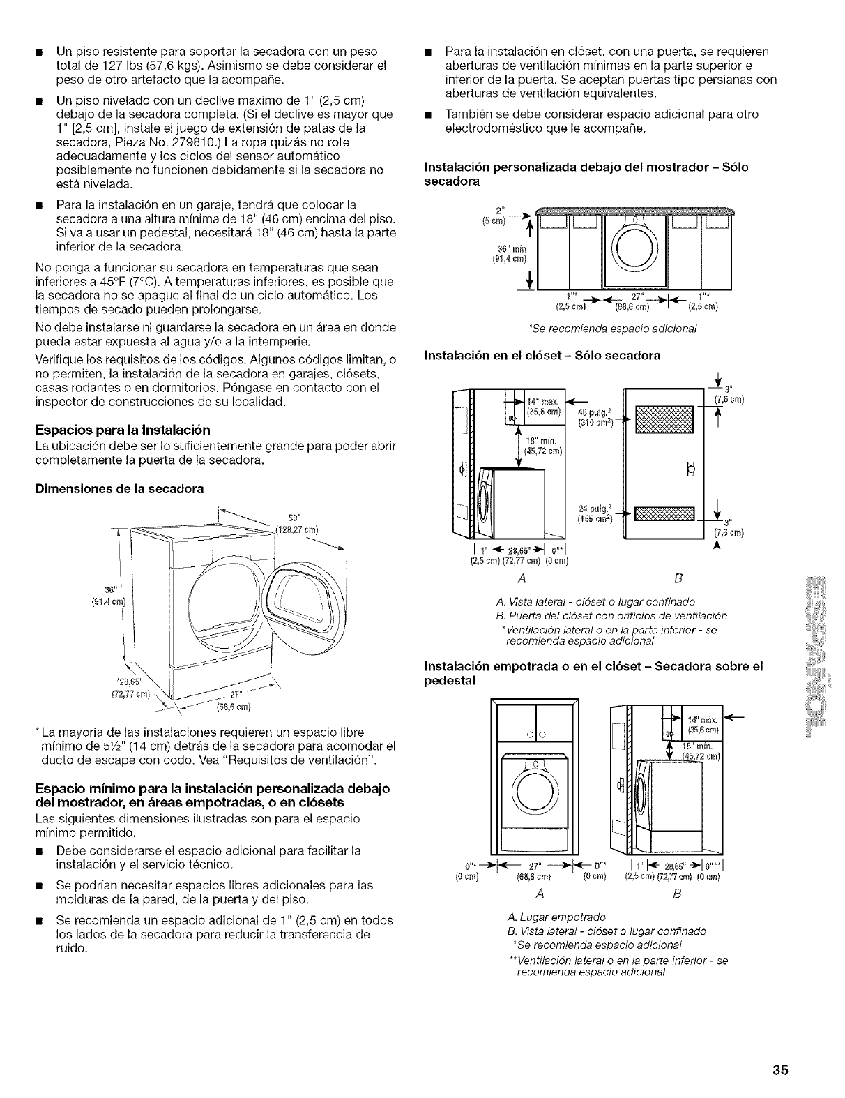
•Un piso resistente para soportar la secadora con un peso
total de 127 Ibs (57,6 kgs). Asimismo se debe considerar el
peso de otro artefacto que la acompa_e.
Un piso nivelado con un declive maximo de 1" (2,5 cm)
debajo de la secadora completa. (Si el declive es mayor que
1" [2,5 cm], instale el juego de extensi6n de patas de la
secadora, Pieza No. 279810.) La ropa quizas no rote
adecuadamente y los ciclos del sensor automatico
posiblemente no funcionen debidamente si la secadora no
esta nivelada.
Para la instalaci6n en un garaje, tendra que colocar la
secadora a una altura mfnima de 18" (46 cm) encima del piso.
Siva a usar un pedestal, necesitara 18" (46 cm) hasta la parte
inferior de la secadora.
No ponga a funcionar su secadora en temperaturas que sean
inferiores a 45°F (7°C). A temperaturas inferiores, es posible que
la secadora no se apague al final de un ciclo automatico. Los
tiempos de secado pueden prolongarse.
No debe instalarse ni guardarse la secadora en un Area en donde
pueda estar expuesta al agua y/o a la intemperie.
Verifique los requisites de los c6digos. Algunos c6digos limitan, o
no permiten, la instalaci6n de la secadora en garajes, cl6sets,
casas rodantes o en dormitories. P6ngase en contacto con el
inspector de construcciones de su Iocalidad.
Espacios para la Instalacibn
La ubicaci6n debe ser Io suficientemente grande para poder abrir
completamente la puerta de la secadora.
Dimensiones de la secadora
(91,4 cm)
L
*28,65"
(72,77 cm}
(68,6 cm)
* La mayoria de las instalaciones requieren un espacio libre
mfnimo de 51/2'' (14 cm) detras de la secadora para acomodar el
ducto de escape con codo. Vea "Requisites de ventilaci6n".
Espacio minimo para la instalacibn personalizada debajo
del mostrador, en &reas empotradas, o en clbsets
Las siguientes dimensiones ilustradas son para el espacio
minimo permitido.
• Debe considerarse el espacio adicional para facilitar la
instalaci6n y el servicio tecnico.
• Se podfian necesitar espacios libres adicionales para las
molduras de la pared, de la puerta y del piso.
• Se recomienda un espacio adicional de 1" (2,5 cm) en todos
los lados de la secadora para reducir la transferencia de
ruido.
Para la instalaci6n en cl6set, con una puerta, se requieren
aberturas de ventilaci6n minimas en la parte superior e
inferior de la puerta. Se aceptan puertas tipo persianas con
aberturas de ventilaci6n equivalentes.
Tambien se debe considerar espacio adicional para otro
electrodomestico que le acompaSe.
Instalaci6n personalizada debajo del mostrador - $61o
secadora
•---_1_-:- 27 ---_1_,_-- 1
(2,5cm) (636era) (2,5cm)
•Se recomienda espacio adicional
Instalaci6n en el clbset - S61o secadora
IL-H f,0o,,o
I 1"_ 28,e5"->-I0"*1
{2,5cm) (72,77cm) (Ocm}
A
48 puIg=2
(310 cr°2}-
24 pulg.2_
(155cm2)
B
_!_ 3 ,,
(7,6 cm)
(7,6cm)
A. Vista lateral -cldset o lugar confinado
B. Puerta del cldset con orificios de ventilacidn
*Ventilacidn lateral o en la parte inferior -se
recomienda espacio adicional
Instalaci6n empotrada oen el clbset -Secadora sobre el
pedestal eel
0"* --_ _--- 27" ---_'_-- 0"*
(0 cm) (66,6cro) (Ocm)
A
".=
I1"1<-_,66"_10"**1
{2,5cm) (72,77cm) {Ocm)
B
A. Lugar empotrado
B. Vista lateral -cldset o lugar confinado
*Se recomienda espacio adicional
**Ventilacidn lateral o en la parte inferior - se
recomienda espacio adicional
35
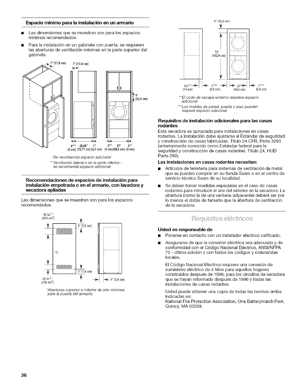
gabinete.
" , 7" (17,8 cm)
m,;....28,05, i,,
Espacio minimo para la instalacibn en un armario
Las dimensiones que se muestran son para los espacios
minimos recomendados.
Para la instalaci6n en un gabinete con puerta, se requieren
las aberturas de ventilaci6n minimas en la parte superior del
O"* 27" 0"*
(0 crn)(72,77 cm) (2,5cm) (0 cm)(68,6cm) (0 cm)
*Se recomienda espacio adicional
**Ventilacidn lateral o en la parte inferior -
se recomienda espacio adicional
9"
(22,9 cm)
Recomendaciones de espacios de instalacibn para
instalacibn empotrada o en el armario, con lavadora y
secadora apiladas
Las dimensiones que se muestran son para los espacios
recomendados.
48 i_=_ *
(310 cm 2}
o
24 in=2 *
(155cm2)
±
3"(7.6cm) ..............................
.................................4
2L
3"(7.8cm) =
J_ ==_1 _ I" (2.5 cm)
*Aberturas superior einferior de aire mfnimas
para la puerta del armario.
5V2"**_ _ I"***
(14 cm) (2,5cm)
, \ /
,\ /
\<..-_/
72"
{182,9 era} --
_i )J
%
f =
(2,5era) {88,8cm)
**El code de escape extemo requiere espacio
adicionaL
***Los moldes de pared, puerta y piso pueden
requerir espacio adicional.
Requisitos de instalacibn adicionales para las casas
rodantes
Esta secadora es apropiada para instalaciones en casas
rodantes. La instalaci6n debe ajustarse al Estandar de seguridad
y construcciTn de casas fabricadas, Titulo 24 CFR, Parte 3280
(anteriormente conocido come Estandar federal para la
seguridad y construcciTn de casas rodantes, Tftulo 24, HUD
Parte 280).
Las instalaciones en casas rodantes necesitan:
• Art_culos de ferreter_a para sistemas de ventilaciTn de metal
que se pueden comprar en su tienda Sears o en el centre de
servicio tecnico Sears de su Iocalidad.
Se deben tomar medidas especiales en el caso de casas
rodantes para introducir el aire del exterior en la secadora. La
abertura (como la de una ventana adyacente) debera ser per
Io menos el doble de tamado que la abertura de ventilaci6n
de la secadora.
Usted es responsable de
• Ponerse en contacto con un instalador electrico calificado.
Asegurarse de que la conexi6n electrica sea adecuada y de
conformidad con el CTdigo Nacional Electrico, ANSI/NFPA
70 - Qltima edici6n y con todos los cTdigos y ordenanzas
locales.
El C6digo Nacional Electrico requiere una conexiTn de
suministro electrico de 4 hilos para aquellos hogares
construidos despues de 1996, para los circuitos de secadora
que se hayan reformado despues de 1996 y todas las
instalaciones de casas rodantes.
Usted puede obtener una copia de todas las normas arriba
indicadas en:
National Fire Protection Association, One Batterymarch Park,
Quincy, MA 02269.
36
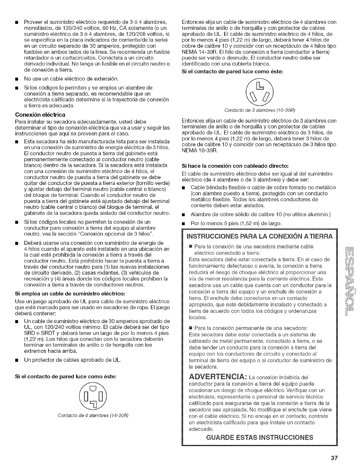
Proveer el suministro electrico requerido de 3 6 4 alambres,
monofasico, de 120/240 voltios, 60 Hz, CA solamente (o un
suministro electrico de 3 6 4 alambres, de 120/208 voltios, si
se especifica en la placa indicadora de corriente/de la serie)
en un circuito separado de 30 amperios, protegido con
fusibles en ambos lados de la linea. Se recomienda un fusible
retardador o un cortacircuitos. Conectela a un circuito
derivado individual. No tenga un fusible en el circuito neutro o
de conexi6n a tierra.
• No use un cable electrico de extensi6n.
Si los c6digos Io permiten y se emplea un alambre de
conexi6n a tierra separado, es recomendable que un
electricista calificado determine si la trayectoria de conexi6n
a tierra es adecuada.
Conexi6n el_ctrica
Para instalar su secadora adecuadamente, usted debe
determinar el tipo de conexi6n electrica que va a usar y seguir las
instrucciones que aquf se proveen para el caso.
• Esta secadora ha side manufacturada lista para ser instalada
en una conexi6n de suministro de energ[a electrica de 3 hilos.
El conductor neutro de puesta a tierra del gabinete esta
permanentemente conectado al conductor neutro (cable
blanco) dentro de la secadora. Si la secadora esta instalada
con una conexi6n de suministro electrico de 4 hilos, el
conductor neutro de puesta a tierra del gabinete se debe
quitar del conductor de puesta a tierra exterior (tornillo verde)
y ajustar debajo del terminal neutro (cable central o blanco)
del bloque de terminal. Cuando el conductor neutro de
puesta a tierra del gabinete este ajustado debajo del terminal
neutro (cable central o blanco) del bloque de terminal, el
gabinete de la secadora queda aislado del conductor neutro.
• Si los c6digos locales no permiten la conexi6n de un
conductor para conexi6n a tierra del equipo al alambre
neutro, vea la secci6n "Conexi6n opcional de 3 hilos".
Debera usarse una conexi6n con suministro de energ[a de
4 hilos cuando el aparato este instalado en una ubicaci6n en
la cual este prohibida la conexi6n a tierra a traves del
conductor neutro. Esta prohibido hacer la puesta a tierra a
traves del conductor neutro para (1) las nuevas instalaciones
de circuito derivado, (2) casas rodantes, (3) veh[culos de
recreaci6n y (4) Areas donde los c6digos locales prohiben la
conexi6n a tierra a traves de conductores neutros.
$i emplea un cable de suministro el_ctrico:
Use un juego aprobado de UL para cable de suministro electrico
que este marcado para ser usado en secadoras de ropa. El juego
debera contener:
• Un cable de suministro electrico de 30 amperios aprobado de
UL, con 120/240 voltios minimo. El cable debera ser del tipo
SRD o SRDT y debera tener un largo de por Io menos 4 pies
(1,22 m). Los hilos que conectan con la secadora deberan
terminar en terminales de anillo o de horquilla con los
extremes hacia arriba.
• Un protector de cables aprobado de UL.
Si el contacto de pared luce come _ste:
Contacto de 4 alambres (14-30R)
Entonces elija un cable de suministro electrico de 4 alambres con
terminales de anillo o de horquilla y con protector de cables
aprobado de UL. El cable de suministro electrico de 4 hilos, de
por Io menos 4 pies (1,22 m) de largo, debera tener 4 hilos de
cobre de calibre 10 y coincidir con un receptaculo de 4 hilos tipo
NEMA 14-30R. El hilo de conexi6n a tierra (conductor a tierra)
puede set verde o desnudo. El conductor neutro debe ser
identificado con una cubierta blanca.
Si el contacto de pared luce come _ste:
Contacto de 3 alambres (10-30R)
Entonces elija un cable de suministro electrico de 3 alambres con
terminales de anillo o de horquilla y con protector de cables
aprobado de UL. El cable de suministro electrico de 3 hilos, de
por Io menos 4 pies (1,22 m) de largo, debera tener 3 hilos de
cobre de calibre 10 y coincidir con un receptaculo de 3 hilos tipo
NEMA 10-30R.
Si hace la conexibn con cableado directo:
El cable de suministro electrico debe ser igual al del suministro
electrico (de 4 alambres o de 3 alambres) y debe ser:
• Cable blindado flexible o cable de cobre forrado no metalico
(con alambre puesto a tierra), protegido con un conducto
metalico flexible. Todos los alambres conductores de
corriente deben estar aislados.
• Alambre de cobre s61ido de calibre 10 (no utilice aluminio.)
• Por Io menos 5 pies (1,52 m) de largo.
INSTRUCCIONES PARA LA CONEXI6N ATIERRA
m Para Ia conexi6n de una secadora mediante cable
electrico conectado a tierra:
Esta secadora debe estar conectada a tierra. En el caso de
funcionamiento defectuoso o aver[a, la conexi6n a tierra
reducira el riesgo de choque el6ctrico ai proporcionar una
via de menor resistencia para Ia corriente eIectrica. Esta
secadora usa un cable que cuenta con un conductor para la
conexi6n a tierra deJequipo y un enchufe de conexi6n a
tierra. Ei enchufe debe conectarse en un contacto
apropiado, que este debidamente instaiado y conectado a
tierra de acuerdo con todos los c6digos y ordenanzas
Jocales.
m Para Ia conexi6n permanente de una secadora:
Esta secadora debe estar conectada a un sistema de
cableado de metal permanente, conectado a tierra, o se
debe tender un conducto para Ia conexi6n a tierra del
equipo con los conductores de circuito y conectado al
terminal de tierra del equipo o al conductor de suministro de
Ja secadora.
ADVERTENOIA: ha conexi6n indebida del
conductor para la conexi6n a tierra deI equipo puede
ocasionar un riesgo de cheque electrico. Verifique con un
eIectricista, representante o personal de servicio t6cnico
catificado para asegurarse de que la conexi6n a tierra de la
secadora sea apropiada. No modifique el enchufe que viene
con et cable electrico. Si no encaja en el contacto, contrate
un electricista calificado para que instale un contacto
adecuado.
GUARDE ESTAS INSTRUCCIONES
37
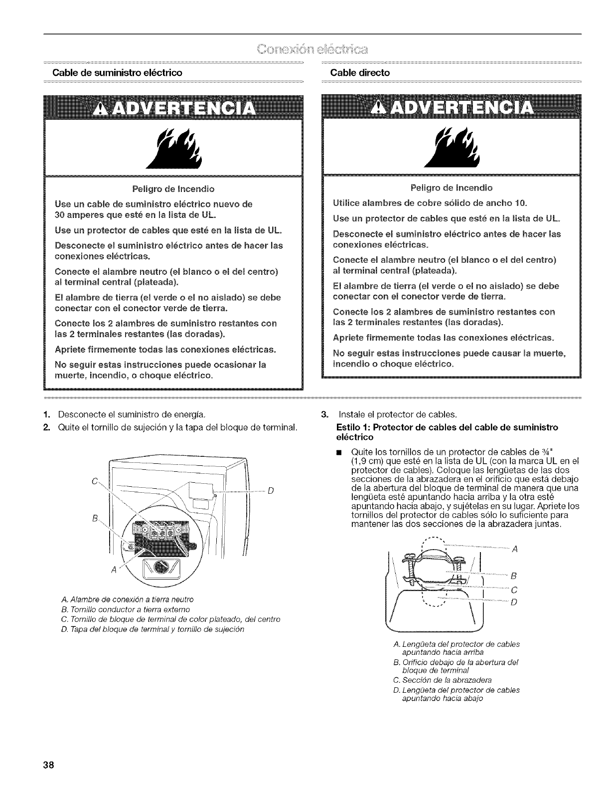
Cable de suministro el_ctrico Cable directo
Peligre de tncendio
Use un cable de suministro electrice nuevo de
30 amperes que este en mamistade ULo
Use un protector de cables que este en Is mietade UL.
Deaconecte el euminiatre electrico antes de hacer mas
cone×iones emectr}cas,
Cenecte el aBambre neutro (eBbmanco e el det centre)
al termina_ centra{ (plateada),
El atambre de tierra (el verde oemno aisiado) se debe
conectar con el conecter verde de t}erra°
Conecte rues2 alambres de sum}nistre restantes con
mas2terminames restantee (Bas doradaa)o
Apdete firmemente todaa lae cone×ienee eiectricae,
No seguir estas instruccienee puede ecas}onar ma
muerte, incend}o, e cheque em6ctr}co,
Peligre de _ncendio
Utilice alambres de cobre s61ido de ancbo 10,
Use un protector de cables que este en mamietade UL°
Deecenecte eBsuminietro electrice antes de bacer lae
cone×}enee electricas,
Conecte e_ alambre neutro (el b_anco eel det centre)
a_terminal centra_ (plateada),
E_alambre de tierra (e_verde eel no aislade) se debe
conectar con e} conecter verde de tierra,
Conecte lee 2 a_ambres de suministro restantes con
lae 2terminales reetantee (_as doradae)o
Apriete firmemente tedae _ascenexionee e_ectricae°
No $eguir eetas instruccienes puede causar _amuerte,
incendio o cheque electrico°
1. Desconecte el suministro de energia.
2. Quite el tornillo de sujeci6n y la tapa del bloque de terminal.
3. Instale el protector de cables.
Estilo 1: Protector de cables del cable de suministro
el_ctrico
Quite los tornillos de un protector de cables de 3_,,
(1,9 cm) que este en la lista de UL (con la marca UL en el
protector de cables). Coloque las lengQetas de las dos
secciones de la abrazadera en el orificio que esta debajo
de la abertura del bloque de terminal de manera que una
lengQeta este apuntando hacia arriba y la otra este
apuntando hacia abajo, y sujetelas en su lugar. Apriete los
tornillos del protector de cables s61o Io suficiente para
mantener las dos secciones de la abrazadera juntas.
A. Atambre de conexidn a tierra neutro
B. Tornillo conductor a tierra extemo
C. Tornillo de bloque de terminal de color plateado, del centro
D. Tapa del bloque de terminal y tornillo de sujecidn
A. Lengf_eta del protector de cables
apuntando hacia arriba
B. Orificio debajo de la abertura del
bloque de terminal
C. Seccidn de la abrazadera
D. LengQeta del protector de cables
apuntando hacia abajo
38
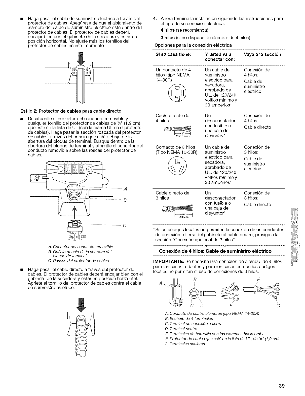
Haga pasar el cable de suministro electrico a traves del
protector de cables. AsegQrese de que el aislamiento de
alambre del cable de suministro electrico este dentro del
protector de cables. El protector de cables debera
encajar bien con el gabinete de la secadora y estar en
posici6n horizontal. No ajuste mas los tornillos del
protector de cables en este memento.
Estilo 2: Protector de cables para cable directo
Desatornille el conector del conducto removible y
cualquier tornillo del protector de cables de 3A" (1,9 cm)
que este en la lista de UL (con la marca UL en el protector
de cables). Haga pasar la secci6n roscada del protector
de cables a traves del orificio que esta debajo de la
abertura del bloque de terminal. Busque dentro de la
abertura del bloque de terminal y atornille el conector del
conducto removible sobre las roscas del protector de
cables.
A
B
A. Conector del conducto removible
B. Orificio debajo de la abertura del
bloque de terminal
C. Roscas del protector de cables
Haga pasar el cable directo a traves del protector de
cables. El protector de cables debera encajar bien con el
gabinete de la secadora y estar en posici6n horizontal.
Apriete el tornillo del protector de cables contra el cable
de suministro electrico.
4. Ahora termine la instalacidn siguiendo las instrucciones para
el tipo de su conexidn electrica:
4 hiloe (se recomienda)
3hilos (si no dispone de alambre de 4 hilos)
Opciones para la conexi6n el_ctrica
Si su casa tiene: Y usted va a Vaya a la secci6n
conectar con:
Un contacto de 4 Un cable de
hilos (tipo NEMA suministro
14-30R) electrico para
secadora,
aprobado de
UL, de 120/240
voltios minimo y
30 amperios*
Conexi6n de
4 hilos:
Cable de
suministro
electrico
Cable directo de Un Conexi6n de
4 hilos desconectador 4 hilos:
con fusible o Cable directo
una caja de
(12,7 cm) disyuntor*
Contacto de 3 hilos Un cable de Conexi6n de
(Tipo NEMA 10-30R) suministro 3 hilos:
(_ electrico para Cable de
secadora, suministro
aprobado de electrico
UL, de 120/240
voltios minimo y
30 amperios*
Cable directo de Un Conexi6n de
3 hilos desconectador 3 hilos:
con fusible o Cable directo
una caja de
disyuntor*
(8,9 cm)
*Sisecci6ndelosconexi6nc6digos"Conexi6na tierralocalesopcionaldelnOgabinetepermitende 3 alhilos",lacableconexi6nneutro,de prosigaun conductora la
Conexibn de 4 hilos: Cable de suministro el_ctrico
IMPORTANTE: Se necesita una conexi6n de alambre de 4 hilos
para las casas rodantes y para los casos en que los c6digos
locales no permitan el uso de conexiones de 3 hilos.
C D E G
A. Contacto de cuatro alambres (tipo NEMA 14-30R)
B. Enchufe de 4 terminales
C. Terminal de cenexidn a tierra
D. Terminal neutro
E. Terminales de horquilla con los extremes hacia arriba
F. Pretecter de cables que est_ en la Iista de UL, de 3/4"(1,9 cm)
G. Terminales anulares
39
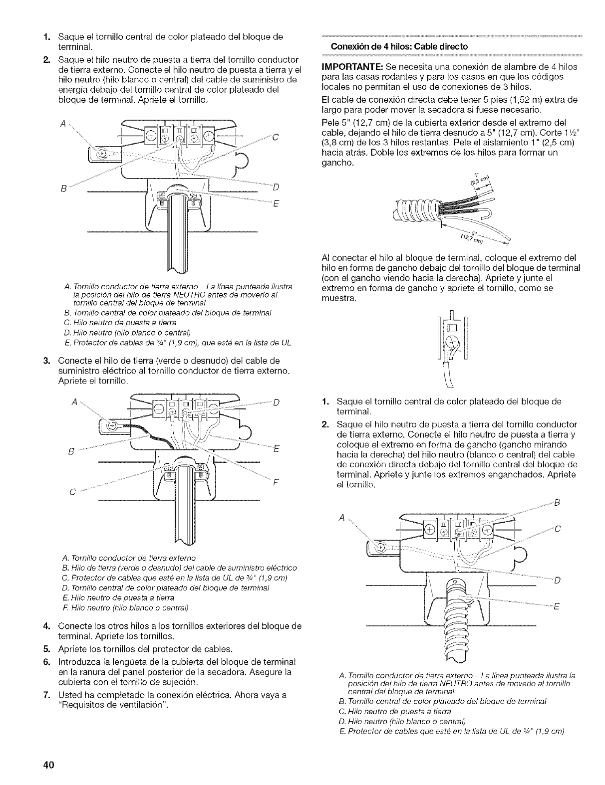
1.
2.
Saque el tornillo central de color plateado del bloque de
terminal.
Saque el hilo neutro de puesta a tierra del tornillo conductor
de tierra externo. Conecte el hilo neutro de puesta a tierra y el
hilo neutro (hilo blanco o central) del cable de suministro de
energfa debajo del tornillo central de color plateado del
bloque de terminal. Apriete el tornillo.
Conexibn de 4 hilos: Cable directo
IMPORTANTE: Se necesita una conexi6n de alambre de 4 hilos
para las casas rodantes y para los casos en que los c6digos
locales no permitan el use de conexiones de 3 hilos.
El cable de conexi6n directa debe tener 5 pies (1,52 m) extra de
largo para poder mover la secadora si fuese necesario.
Pele 5" (12,7 cm) de la cubierta exterior desde el extreme del
cable, dejando el hilo de tierra desnudo a 5" (12,7 cm). Corte 11/2"
(3,8 cm) de los 3 hilos restantes. Pele el aislamiento 1" (2,5 cm)
hacia atras. Doble los extremos de los hilos para formar un
gancho.
3=
A. Tornillo conductor de tierra extemo - La Ifnea punteada flustra
la posicidn del hflo de tierra NEUTRO antes de moverlo al
tomillo central del bloque de terminal
B. Tornillo central de color plateado del bloque de terminal
C. Hilo neutro de puesta a tierra
D. Hilo neutro (hflo blanco o central)
E. Protector de cables de 3/4"(1,9 cm), que est_ en la lista de UL
Conecte el hilo de tierra (verde o desnudo) del cable de
suministro electrico al tornillo conductor de tierra externo.
Apriete el tornillo.
AI conectar el hilo al bloque de terminal, coloque el extreme del
hilo en forma de gancho debajo del tornillo del bloque de terminal
(con el gancho viendo hacia la derecha). Apriete y junte el
extremo en forma de gancho y apriete el tornillo, como se
muestra.
1=
2.
Saque el tornillo central de color plateado del bloque de
terminal.
Saque el hilo neutro de puesta a tierra del tornillo conductor
de tierra externo. Conecte el hilo neutro de puesta a tierra y
coloque el extremo en forma de gancho (gancho mirando
hacia la derecha) del hilo neutro (blanco o central) del cable
de conexi6n directa debajo del tornillo central del bloque de
terminal. Apriete y junte los extremos enganchados. Apriete
el tornillo.
A_
A. Tomillo conductor de tierra externo
B. Hilo de tierra (verde o desnudo) del cable de suministro el_ctrico
C. Protector de cables que est# en la lista de UL de _/_"(!,9 cm)
D. Tomillo central de color plateado del bloque de terminal
E. Hilo neutro de puesta a tierra
FHilo neutro (hilo blanco o central)
4. Conecte los otros hilos a los tornillos exteriores del bloque de
terminal. Apriete los tornillos.
5. Apriete los tornillos del protector de cables.
6. Introduzca la lengQeta de la cubierta del bloque de terminal
en la ranura del panel posterior de la secadora. Asegure la
cubierta con el tornillo de sujeci6n.
7. Usted ha completado la conexi6n electrica. Ahora vaya a
"Requisites de ventilaci6n".
D
E
A. Tornillo conductor de tierra extemo - La Ifnea punteada flustra la
posicidn del hilo de tierra NEUTRO antes de moverlo al tornillo
central del bloque de terminal
B. Tomillo central de color plateado del bloque de terminal
C. Hilo neutro de puesta a tierra
D. Hilo neutro (hilo blanco o central)
E. Protector de cables que est_ en la lista de UL de _/4"(1,9 cm)
40
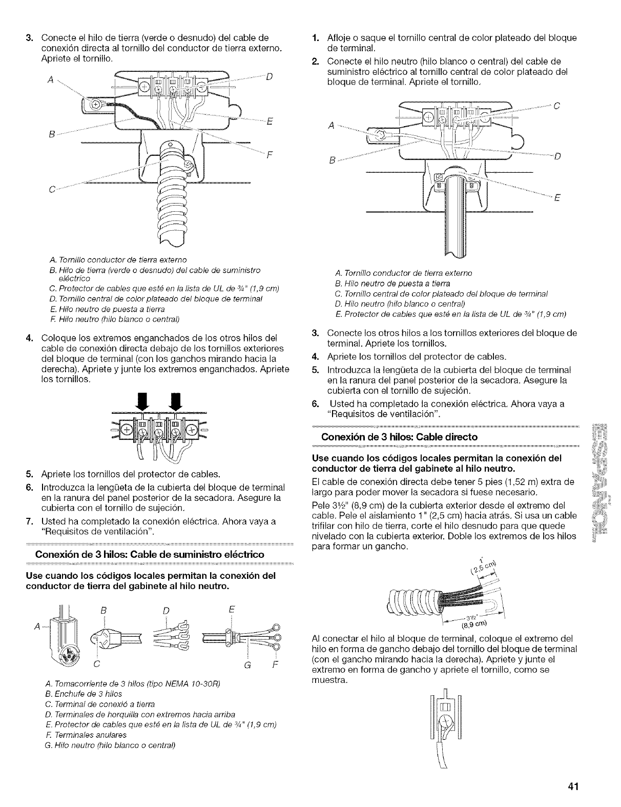
Conecte el hilo de tierra (verde o desnudo) del cable de
conexi6n directa al tornillo del conductor de tierra externo.
Apriete el tomillo.
1. Afloje o saque el tornillo central de color plateado del bloque
de terminal.
2. Conecte el hilo neutro (hilo blanco o central) del cable de
suministro electrico al tornillo central de color plateado del
bloque de terminal. Apriete el tornillo.
A. Tomillo conductor de tierra externo
B. Hilo de tierra (verde o desnudo) del cable de suministro
el_ctrico
C. Protector de cables que est_ en la Iista de UL de 3/4"(1,9 cm)
D. Tomillo central de color plateado del bloque de terminal
E. Hilo neutro de puesta a tierra
FHilo neutro (hilo blanco o central)
Coloque los extremos enganchados de los otros hilos del
cable de conexi6n directa debajo de los tornillos exteriores
del bloque de terminal (con los ganchos mirando hacia la
derecha). Apriete y junte los extremos enganchados. Apriete
los tornillos.
!! !!
5. Apriete los tornillos del protector de cables.
6. Introduzca la lengQeta de la cubierta del bloque de terminal
en la ranura del panel posterior de la secadora. Asegure la
cubierta con el tornillo de sujeci6n.
7. Usted ha completado la conexi6n electrica. Ahora vaya a
"Requisitos de ventilaci6n".
Conexibn de 3 hilos: Cable de suministro el_ctrico
Use cuando los cbdigos locales permitan la conexi6n del
conductor de tierra del gabinete al hilo neutro.
ii,
C
E
G F
A. Tomacorriente de 3 hilos (tipo NEMA 10-30R)
B. Enchufe de 3 hilos
C. Terminal de conexid a tierra
D. Terminales de horquilla con extremes hacia arriba
E. Protector de cables que est_ en la lista de UL de 3/4"(1,9 cm)
Terminales anulares
G. Hilo neutro (hilo blanco o central)
A. Tornillo conductor de tierra externo
B. Hilo neutro de puesta a tierra
C. Tornillo central de color plateado del bloque de terminal
D. Hilo neutro (hilo blanco o central)
E. Protector de cables que est_ en la lista de UL de _/_"(!,9 cm)
3. Conecte los otros hilos a los tornillos exteriores del bloque de
terminal. Apriete los tornillos.
4. Apriete los tornillos del protector de cables.
5. Introduzca la lengQeta de la cubierta del bloque de terminal
en la ranura del panel posterior de la secadora. Asegure la
cubierta con el tornillo de sujeci6n.
6. Usted ha completado la conexi6n el6ctrica. Ahora vaya a
"Requisitos de ventilaci6n".
Conexibn de 3 hilos: Cable directo
Use cuando los cbdigos locales permitan la conexi6n del
conductor de tierra del gabinete al hilo neutro.
El cable de conexi6n directa debe tener 5 pies (1,52 m) extra de
largo para poder mover la secadora si fuese necesario.
Pele 31/d' (8,9 cm) de la cubierta exterior desde el extreme del
cable. Pele el aislamiento 1" (2,5 cm) hacia atras. Si usa un cable
trifilar con hilo de tierra, corte el hilo desnudo para que quede
nivelado con la cubierta exterior. Doble los extremos de los hilos
para formar un gancho.
AI conectar el hilo al bloque de terminal, coloque el extremo del
hilo en forma de gancho debajo del tornillo del bloque de terminal
(con el gancho mirando hacia la derecha). Apriete y junte el
extremo en forma de gancho y apriete el tornillo, come se
muestra.
41
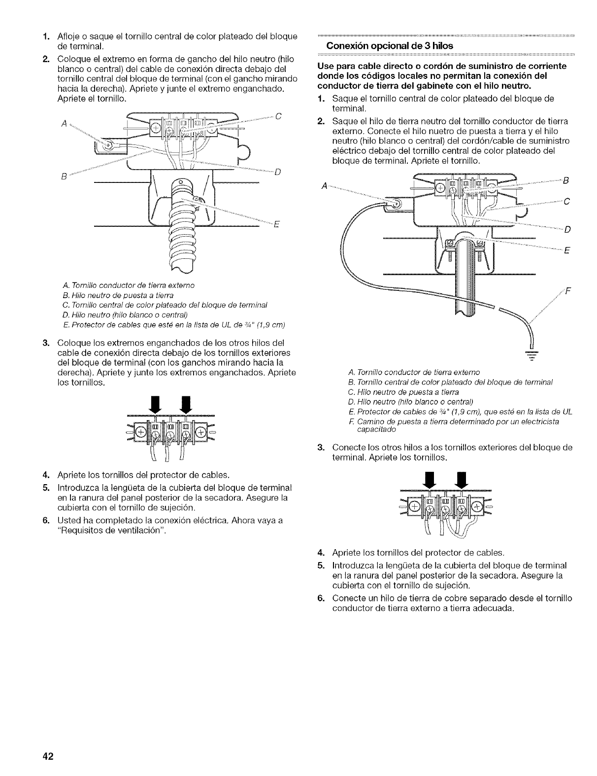
1=
2.
3=
Afloje o saque el tornillo central de color plateado del bloque
de terminal.
Coloque el extremo en forma de gancho del hilo neutro (hilo
blanco o central) del cable de conexi6n directa debajo del
tornillo central del bloque de terminal (con el gancho mirando
hacia la derecha). Apriete y junte el extreme enganchado.
Apriete el tornillo.
A. Tornilloconductor de tierra externo
B. Hilo neutro depuesta a tierra
C. Tornillocentral de color plateado del bloque de terminal
D.Hilo neutro (hilo blanco o central)
E.Protector de cables que est_ en la Iista de UL de 3/4"(1,9 cm)
Coloque los extremos enganchados de los otros hilos del
cable de conexi6n directa debajo de los tornillos exteriores
del bloque de terminal (con los ganchos mirando hacia la
derecha). Apriete y junte los extremes enganchados. Apriete
los tornillos.
!I !!
4. Apriete los tornillos del protector de cables.
5. Introduzca la lengQeta de la cubierta del bloque de terminal
en la ranura del panel posterior de la secadora. Asegure la
cubierta con el tornillo de sujeci6n.
6. Usted ha completado la conexi6n electrica. Ahora vaya a
"Requisites de ventilaci6n".
Conexibn opcional de 3 hilos
Use para cable directo o cord6n de suministro de corriente
donde los cbdigos locales no permitan la conexibn del
conductor de tierra del gabinete con el hilo neutro.
1. Saque el tornillo central de color plateado del bloque de
terminal.
2. Saque el hilo de tierra neutro del tornillo conductor de tierra
externo. Conecte el hilo nuetro de puesta a tierra y el hilo
neutro (hilo blanco o central) del cord6n/cable de suministro
electrico debajo del tornillo central de color plateado del
bloque de terminal. Apriete el tornillo.
3=
A. Tornillo conductor de tierra externo
B. Tornillo central de color plateado del bloque de terminal
C. Hilo neutro de puesta a tierra
D. Hilo neutro (hilo blanco o central)
E. Protector de cables de 3/4"(1,9 cm), que est_ en la lista de UL
FCamino de puesta a tierra determinado por un electricista
capacitado
Conecte los otros hilos a los tornillos exteriores del bloque de
terminal. Apriete los tornillos.
!! !!
4. Apriete los tornillos del protector de cables.
5. Introduzca la lengQeta de la cubierta del bloque de terminal
en la ranura del panel posterior de la secadora. Asegure la
cubierta con el tornillo de sujeci6n.
6. Conecte un hilo de tierra de cobre separado desde el tornillo
conductor de tierra externo a tierra adecuada.
42
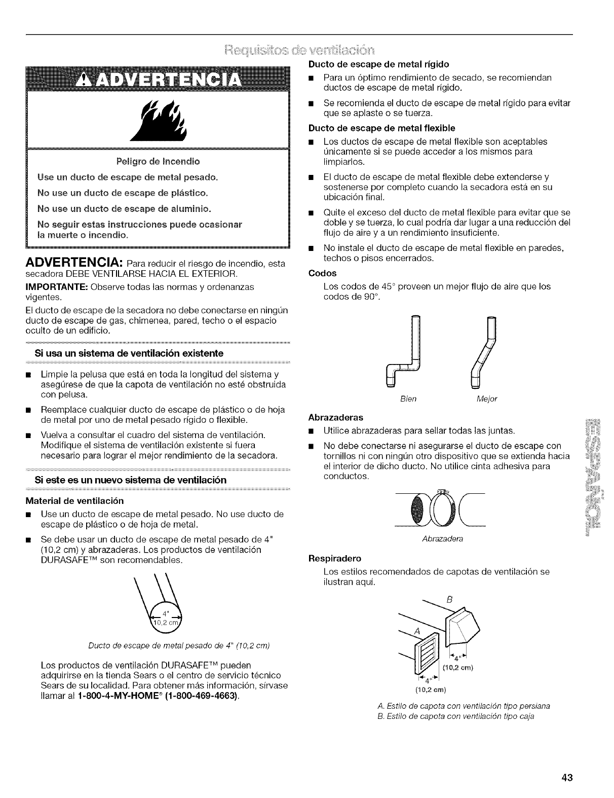
Peligro de Incendie
Use un ducto de escape de metam pesade.
No use un ducte de escape de pmasticeo
No use un ducte de escape de aluminio.
No seguir estas instrucciones puede ocasionar
la muerte o ineendie.
ADMERTENCIA: Para reducir el riesgo de incendio, esta
secadora DEBE VENTILARSE HACIA EL EXTERIOR.
IMPORTANTE: Observe todas las normas y ordenanzas
vigentes.
El ducto de escape de la secadora no debe conectarse en ningQn
ducto de escape de gas, chimenea, pared, techo o el espacio
oculto de un edificio.
Si usa un sistema de ventilacibn existente
• Limpie la pelusa que esta en toda la Iongitud del sistema y
asegQrese de que la capota de ventilaci6n no este obstruida
con pelusa.
• Reemplace cualquier ducto de escape de plastico o de hoja
de metal per uno de metal pesado rfgido o flexible.
• Vuelva a consultar el cuadro del sistema de ventilaci6n.
Modifique el sistema de ventilaci6n existente si fuera
necesario para Iograr el mejor rendimiento de la secadora.
Si este es un nuevo sistema de ventilacibn
Material de ventilaci6n
• Use un ducto de escape de metal pesado. No use ducto de
escape de plastico o de hoja de metal.
• Se debe usar un ducto de escape de metal pesado de 4"
(10,2 cm) y abrazaderas. Los productos de ventilaci6n
DURASAFE TM son recomendables.
Ducto de escape de metal pesado de 4" (10,2 cm)
Los productos de ventilaci6n DURASAFE TM pueden
adquirirse en la tienda Sears o el centre de servicio tecnico
Sears de su Iocalidad. Para obtener mas informaci6n, sirvase
®
Ilamar al 1-800-4-MY-HOME (1-800-469-4663}.
Ducto de escape de metal rigido
• Para un 6ptimo rendimiento de secado, se recomiendan
ductos de escape de metal rigido.
• Se recomienda el ducto de escape de metal rigido para evitar
que se aplaste o se tuerza.
Ducto de escape de metal flexible
• Los ductos de escape de metal flexible son aceptables
Qnicamente si se puede acceder a los mismos para
limpiarlos.
• El ducto de escape de metal flexible debe extenderse y
sostenerse per complete cuando la secadora esta en su
ubicaci6n final.
• Quite el exceso del ducto de metal flexible para evitar que se
doble y se tuerza, Io cual podria dar lugar a una reducci6n del
flujo de aire y a un rendimiento insuficiente.
• No instale el ducto de escape de metal flexible en paredes,
techos o pisos encerrados.
Codes
Los codes de 45 ° proveen un mejor flujo de aire que los
codes de 90°.
Abrazaderas
9
Bien Meier
Utilice abrazaderas para sellar todas las juntas.
No debe conectarse ni asegurarse el ducto de escape con
tornillos ni con ningQn otro dispositivo que se extienda hacia
el interior de dicho ducto. No utilice cinta adhesiva para
conductos.
Abrazadera
Respiradero
Los estilos recomendados de capotas de ventilaci6n se
ilustran aqui.
B
(10,2cm)
(10,2cm)
A. Estilo de capota con ventilacidn tipo persiana
B. Estilo de capota con ventilacidn tipo caja
43
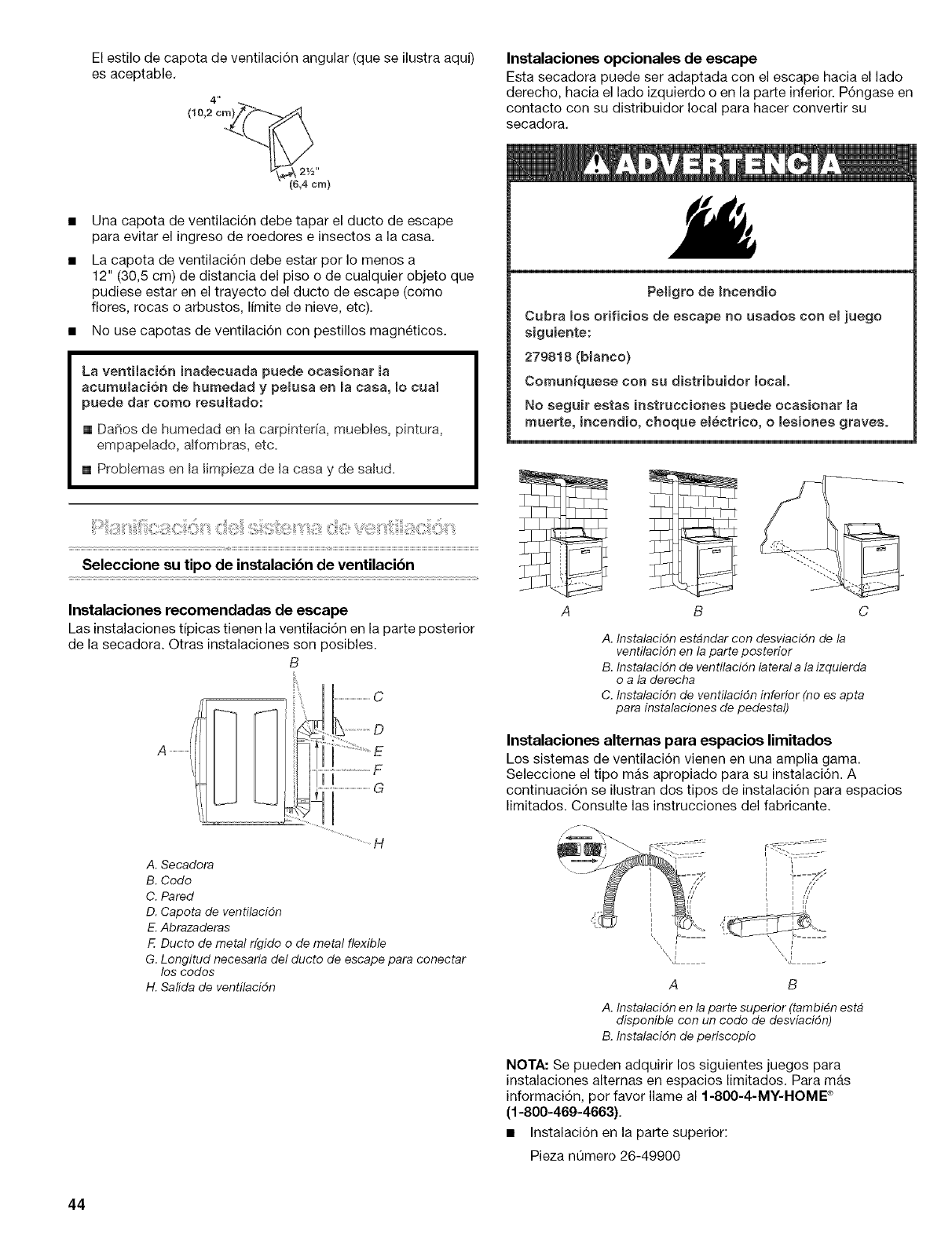
El estilo de capota de ventilaci6n angular (que se ilustra aqu0
es aceptable.
4"
(10,2 cm_
v_ 21/2"
• (6,4cm)
Una capota de ventilaci6n debe tapar el ducto de escape
para evitar el ingreso de roedores e insectos a la casa.
La capota de ventilaci6n debe estar por Io menos a
12" (30,5 cm) de distancia del piso o de cualquier objeto que
pudiese estar en el trayecto del ducto de escape (como
flores, rocas o arbustos, Ifmite de nieve, etc).
• No use capotas de ventilaci6n con pestillos magneticos.
La ventilaci6n inadecuada puede ocasionar ma
acumulaci6n de humedad y peiusa en macasa, Io cual
puede dar como resuitado:
[] DaSos de humedad en Ia carpinteda, muebtes, pintura,
empapelado, alfombras, etc=
[] Problemas en la limpieza de la casa y de salud=
Seleccione su tipo de instalacibn de ventilacibn
Instalaciones recomendadas de escape
Las instalaciones tipicas tienen la ventilaci6n en la parte posterior
de la secadora. Otras instalaciones son posibles.
B
A
....................................C
.............................F
....................................G
A. Secadora
B. Codo
C. Pared
D. Capota de ventilacidn
E. Abrazaderas
FDucto de metal rfgido o de metal flexible
G. Longitud necesaria del ducto de escape para conectar
los codos
H. Salida de ventilacidn
Instalaciones opcionales de escape
Esta secadora puede ser adaptada con el escape hacia el lado
derecho, hacia el lado izquierdo o en la parte inferior. P6ngase en
contacto con su distribuidor local para hacer convertir su
secadora.
Peligro de Incendio
Cubra los orificios de escape no usados con emjuego
siguiente:
279818 (blanco)
Comuniquese con su distribuidor local
No seguir estas instrucciones puede ocasionar Ba
rnuerte, incendio, choque em_ctrico, o lesiones graves.
A B
A. Instalacidn estbndar con desviacidn de la
ventilacidn en la parte posterior
B. Instalacidn de ventilacidn lateral a la izquierda
o a la derecha
C. Instalacidn de ventilacidn inferior (no es apta
para instalaciones de pedestal)
Instalaciones alternas para espacios limitados
Los sistemas de ventilaci6n vienen en una amplia gama.
Seleccione el tipo mas apropiado para su instalaci6n. A
continuaci6n se ilustran dos tipos de instalaci6n para espacios
limitados. Consulte las instrucciones del fabricante.
= l/
• i
A B
A. Instalacidn en la parte superior (tambi#n est#
disponible con un codo de desviacidn)
B. Instalacidn de periscopio
NOTA: Se pueden adquirir los siguientes juegos para
instalaciones alternas en espacios limitados. Para mas
informacidn, por favor Ilame al 1-80O-4-MY-HOME ®
(1-800-469-4663).
• Instalaci6n en la parte superior:
Pieza nQmero 26-49900
44
Instalacidn de periscopio (Para usar si hay desacoplo entre el
ducto de escape de la secadora y el ducto de escape de la
pared):
Pieza n0mero 26-49901 - Desacoplo de menos de
5" (12,7 cm)
Pieza n0mero 26-49908- Desacoplo de 5" (12,7 cm) a
18" (45,72 cm)
Pieza n0mero 26-49904 - Desacoplo de 18" (45,72 cm) a
29" (73,66 cm)
Pieza n0mero 26-49905 - Desacoplo de 29" (73,66 cm) a
50" (127 cm)
Previsiones especiales para las instalaciones en casas
rodantes
El ducto de escape debera sujetarse firmemente en un lugar no
infiamable de la estructura de la casa rodante y no debe terminar
debajo de la casa rodante. El ducto de escape debe terminar en
el exterior.
Determinacibn de la via del ducto de escape
• Seleccione la vfa que proporcione el trayecto mas recto y
directo al exterior.
• Planifique la instalaci6n a fin de usar el menor n0mero posible
de codes y vueltas.
• Cuando use los codos o haga vueltas, deje todo el espacio
que sea posible.
• Doble el ducto gradualmente para evitar torceduras.
• Use la menor cantidad posible de vueltas de 90°.
Determinacibn de la Iongitud del ducto de escape y de
los codos necesarios para obtener un 6ptimo
rendimiento de secado
• Use el cuadro del sistema de ventilaci6n a continuaci6n para
determinar el tipo de material para ducto y la combinaci6n de
capota aceptable a usar.
NOTA: No use tendidos de ducto de escape mas largos que
los especificados en el cuadro del sistema de ventilaci6n. Los
sistemas de ventilaci6n mas largos que los especificados:
• Acortaran la vida de la secadora.
• Reduciran el rendimiento, dando lugar a tiempos de
secado mas largos y un aumento en el consume de
energfa,
El cuadro del sistema de ventilaci6n indica los requisitos de
ventilaci6n que le ayudaran a alcanzar el mejor rendimiento de
secado,
Cuadro del sistema de ventilacibn
NOTA: Las instalaciones de ventilaci6n laterales e inferiores
tienen una vuelta de 90° dentro de la secadora, Para determinar
la Iongitud maxima de ventilaci6n, agregue una vuelta de 90 ° al
cuadro.
No. de Tipo de Capotas de Capotas
vueltas ducto ventilaci6n de angulares
de 90° caja o tipo
o persianas
codos
0 Metal rigido 64 pies (20 m) 58 pies (17,7 m)
Metal flexible 36 pies (11 m) 28 pies (8,5 m)
1Metal rigido 54 pies (16,5 m) 48 pies (14,6 m)
Metal flexible 31 pies (9,4 m) 23 pies (7 m)
2 Metal rigido 44 pies (13,4 m) 38 pies (11,6 m)
Metal flexible 27 pies (8,2 m) 19 pies (5,8 m)
3Metal rigido 35 pies (10,7 m) 29 pies (8,8 m)
Metal flexible 25 pies (7,6 m) 17 pies (5,2 m)
4 Metal rigido 27 pies (8,2 m) 21 pies (6,4 m)
Metal flexible 23 pies (7 m) 15 pies (4,6 m)
1. Instale la capota de ventilaci6n. Emplee una masilla de
calafateo para sellar la abertura de la pared externa alrededor
de la capota de ventilaci6n,
2. Conecte el ducto de escape a la capota de ventilaci6n. El
ducto de escape debe encajar dentro de la capota de
ventilaci6n. Asegure el ducto de escape a la capota de
ventilaci6n con una abrazadera de 4" (10,2 cm).
3. Extienda el ducto de escape a la ubicaci6n de la secadora,
Use la trayectoria mas recta posible. Vea "Determinaci6n de
la via del ducto de escape" en "Planificaci6n del sistema de
ventilaci6n", Evite giros de 90 °, Use abrazaderas para sellar
todas las juntas. No use cinta adhesiva para conductos,
tornillos ni otros dispositivos de fijaci6n que se extiendan
dentro del ducto de escape, para fijar el mismo,
45
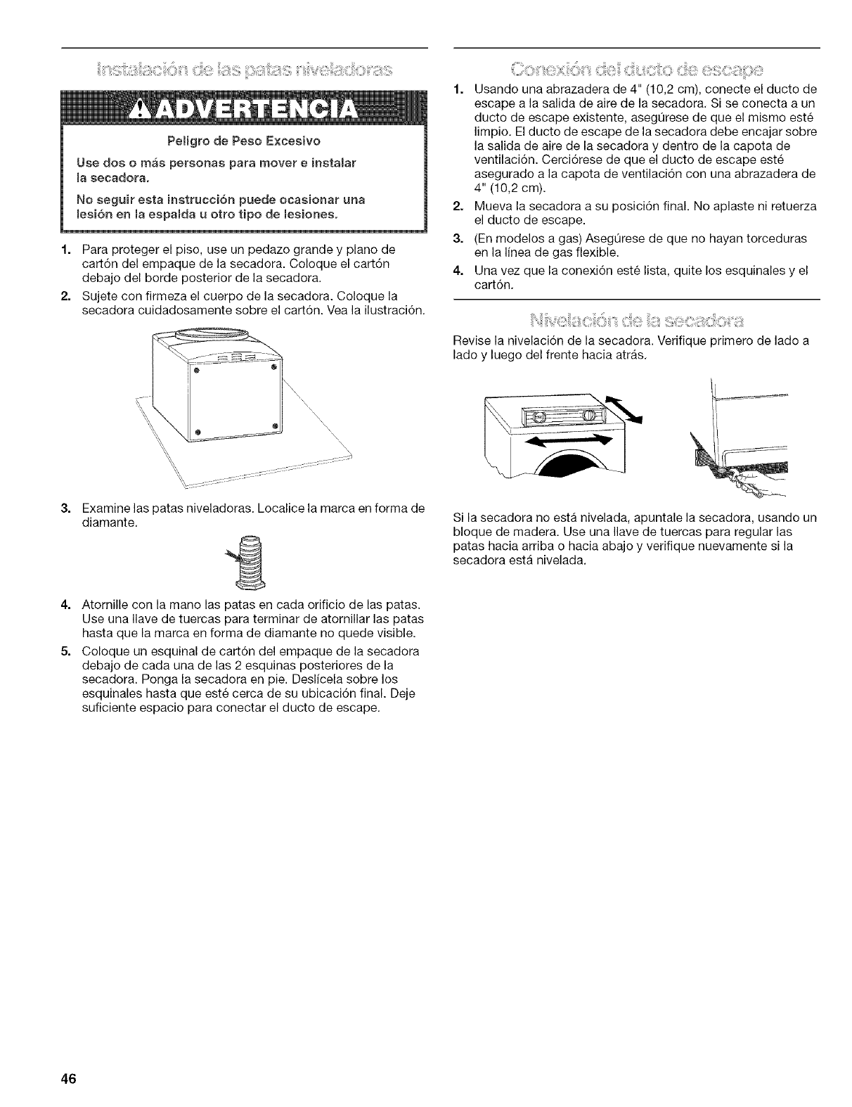
Petigre de Pese Excesive
Use des e mas persenas para mever einstalar
la secadera.
No seguir esta instracci6n puede ecasienar una
lesi6n en la espalda u otto tipo de lesiones.
1. Para proteger el pise, use un pedaze grande y plane de
cart6n del empaque de la secadora. Coloque el cart6n
debaje del berde posterior de la secadora.
2. Sujete cen firmeza el cuerpe de la secadora. Celoque la
secadera cuidadosamente sobre el cart6n. Vea la ilustraci6n.
i \X
\\\\\
\\\\\\\
1. Usande una abrazadera de 4" (10,2 cm), cenecte el ducto de
escape a la salida de aire de la secadora. Si se conecta a un
ducto de escape existente, asegQrese de que el mismo este
limpie. El ducto de escape de la secadora debe encajar sobre
la salida de aire de la secadera y dentre de la capeta de
ventilaci6n. Cerci6rese de que el ducte de escape este
asegurado a la capota de ventilaci6n cen una abrazadera de
4" (10,2 cm).
2. Mueva la secadora a su pesici6n final. No aplaste ni retuerza
el ducto de escape.
3. (En modeles a gas) Asegt]rese de que no hayan terceduras
en la linea de gas flexible.
4. Una vez que la cenexi6n este lista, quite les esquinales y el
cart6n.
Revise la nivelaci6n de la secadora. Verifique primero de lado a
lade y luege del frente hacia atrfls.
3.
4.
5.
Examine las patas niveladoras. Localice la marca en forma de
diamante.
Atornille con la mano las patas en cada orificio de las patas.
Use una Ilave de tuercas para terminar de atornillar las patas
hasta que la marca en ferma de diamante ne quede visible.
Celoque un esquinal de cart6n del empaque de la secadora
debaje de cada una de las 2 esquinas pesterieres de la
secadora. Ponga la secadora en pie. Deslicela sobre les
esquinales hasta que este cerca de su ubicaci6n final. Deje
suficiente espacie para conectar el ducto de escape.
Si la secadora no esta nivelada, apuntale la secadora, usando un
bleque de madera. Use una Ilave de tuercas para regular las
patas hacia arriba o hacia abajo y verifique nuevamente si la
secadera estfi nivelada.
46
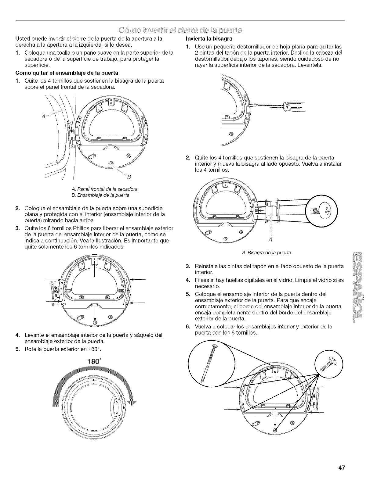
_ii:;iiiiiil)_i:ii!i_l!ii!iJOii!ii%_=(!!!!_i2_ii:;iiit¸¸¸¸_;i!:i_iiC:iii_;i!!_)iiii!b(]:iiii(i!)!ii;_i!!!!;;ii_:]:_iLt_ii!!)I_:ii:;)i:!:!!l
Usted puede invertir el cierre de la puerta de la apertura a la
derecha a la apertura a la izquierda, si Io desea.
1. Coloque una toalla o un paso suave en la parte superior de la
secadora o de la superficie de trabajo, para proteger la
superficie.
C6mo quitar el ensamblaje de la puerta
1. Quite los 4 tornillos que sostienen la bisagra de la puerta
sobre el panel frontal de la secadora.
Invierta la bisagra
1. Use un peque5o destornillador de hoja plana para quitar las
2 cintas del tap6n de la puerta interior. Deslice la cabeza del
destornillador debajo los tapones, siendo cuidadoso de no
rayar la superficie interior de la secadora. Levantela.
@
Quite los 4 tornillos que sostienen la bisagra de la puerta
interior y mueva la bisagra al lade opuesto. Vuelva a instalar
los 4 tornillos.
A. Panel frontal de la secadora
B. Ensamblaje de la puerta
2. Coloque el ensamblaje de la puerta sobre una superficie
plana y protegida con el interior (ensamblaje interior de la
puerta) mirando hacia arriba.
3. Quite los 6 tornillos Philips para liberar el ensamblaje exterior
de la puerta del ensamblaje interior de la puerta, como se
indica a continuaci6n. Vea la ilustraci6n. Es importante que
quite solamente los 6 tornillos indicados.
4. Levante el ensamblaje interior de la puerta y saquelo del
ensamblaje exterior de la puerta.
5. Rote la puerta exterior en 180°.
180"
A
A. Bisagra de la puerta
3. Reinstale las cintas del tap6n en el lado opuesto de la puerta
interior.
4. Fijese si hay huellas digitales en el vidrio. Limpie el vidrio si es
necesario.
5. Coloque el ensamblaje interior de la puerta dentro del
ensamblaje exterior de la puerta, Para que encaje
correctamente, el borde del ensamblaje interior de la puerta
encaja completamente dentro del borde del ensamblaje
exterior de la puerta,
6. Vuelva a colocar los ensamblajes interior y exterior de la
puerta con los 6 tornillos,
47
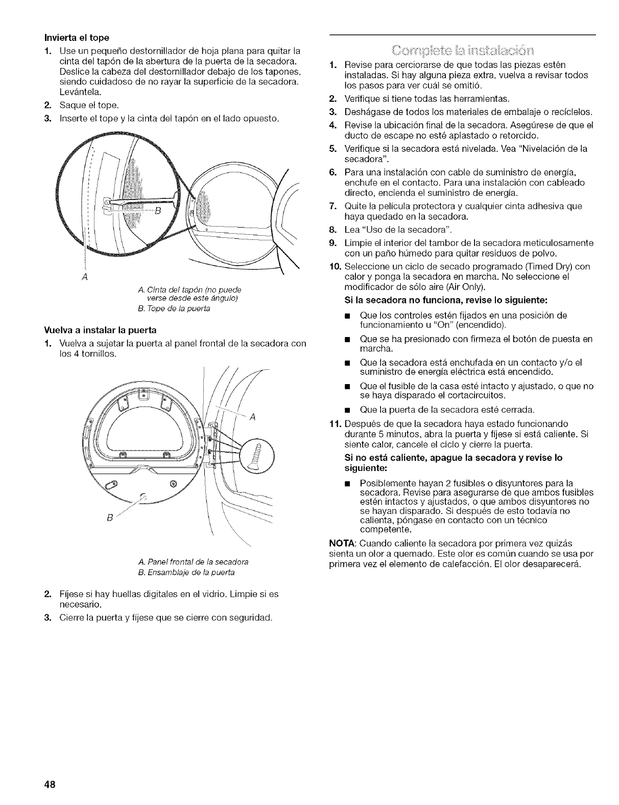
Invierta el tope
1. Use un pequer_o destornillador de hoja plana para quitar la
cinta del tapdn de la abertura de la puerta de la secadora.
Deslice la cabeza del desternillador debajo de los tapones,
siende cuidadose de no rayar la superficie de la secadera.
Levantela.
2. Saque el tope.
3. Inserte el tope y la cinta del tapdn en el lado opuesto.
A. Cinta del tap6n (no puede
verse desde este bngulo)
B. Tope de la puerta
Vuelva a instalar la puerta
1. Vuelva a sujetar la puerta al panel frontal de la secadora con
los 4 tornillos.
®
A. Panel frontal de la secadora
B. Ensamblaje de la puerta
2. Fijese si hay huellas digitales en el vidrio. Limpie si es
necesario.
3. Cierre la puerta y fijese que se cierre con seguridad.
1. Revise para cerciorarse de que todas las piezas esten
instaladas. Si hay alguna pieza extra, vuelva a revisar todos
los pasos para ver cual se omiti6.
2. Verifique si tiene todas las herramientas.
3. Deshagase de todos los materiales de embalaje o recfclelos.
4. Revise la ubicaci6n final de la secadora. AsegQrese de que el
ducto de escape no este aplastado o retorcido.
5. Verifique si la secadora esta nivelada. Vea "Nivelaci6n de la
secadora".
6. Para una instalaci6n con cable de suministro de energia,
enchufe en el contacto. Para una instalaci6n con cableado
directo, encienda el suministro de energia.
7. Quite la pelicula protectora y cualquier cinta adhesiva que
haya quedado en la secadora.
8. Lea "Use de la secadora".
9. Limpie el interior del tambor de la secadora meticulosamente
con un paso hQmedo para quitar residuos de polvo.
10. Seleccione un ciclo de secado programado (Timed Dry) con
calor y ponga la secadora en marcha. No seleccione el
modificador de s61o aire (Air Only).
Si la secadora no funciona, revise Io siguiente:
• Que los controles esten fijados en una posici6n de
funcionamiento u "On" (encendido).
• Que se ha presionado con firmeza el bot6n de puesta en
marcha.
11.
• Que la secadora esta enchufada en un contacto y/o el
suministro de energfa electrica esta encendido.
• Que el fusible de la casa este intacto y ajustado, o que no
se haya disparado el cortacircuitos.
• Que la puerta de la secadora este cerrada.
Despues de que la secadora haya estado funcionando
durante 5 minutes, abra la puerta y fijese siesta caliente. Si
siente calor, cancele el ciclo y cierre la puerta.
Si no esta caliente, apague la secadora y revise Io
siguiente:
• Posiblemente hayan 2 fusibles o disyuntores para la
secadora. Revise para asegurarse de que ambos fusibles
esten intactos y ajustados, o que ambos disyuntores no
se hayan disparado. Si despues de esto todavfa no
calienta, p6ngase en contacto con un tecnico
competente.
NOTA: Cuando caliente la secadora por primera vez quizas
sienta un olor a quemado. Este olor es comQn cuando se usa per
primera vez el elemento de calefacci6n. El olor desaparecer&
48
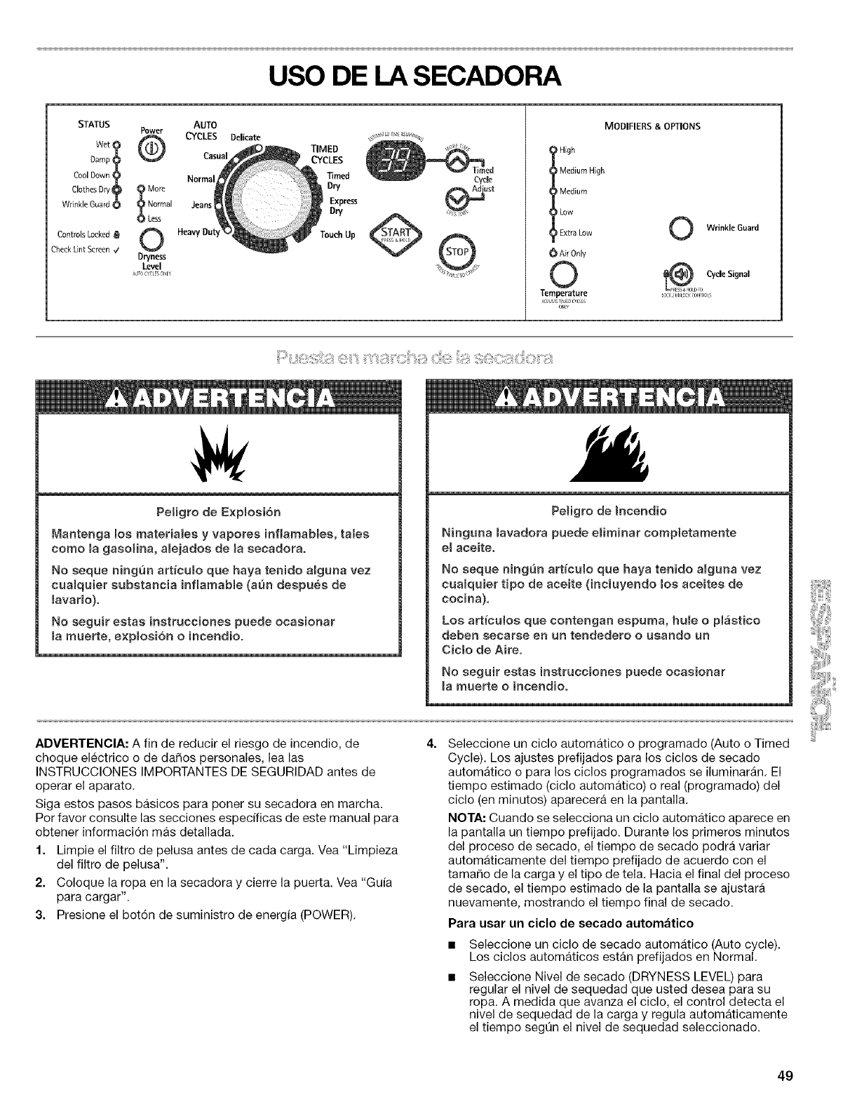
USO DE LA SECADORA
MODIFIERS &OPTIONS
STATUS AUTO
Power CYCLES Delicate
Damp _ Casual
Cool Down Normal
Clothes D_/_ :_ More
Wrinkle Guard O Normal Jeans
0 Less
Controls Locked a
Check Lint Screen VDryness
Level
_TO C_qB or/l¥
TIMED
CYCLES
Timed
Dry
Express
Dry
TouchUp
I igh
Medium High
Medium
I LowExtra Low
6 Air Only
©
Temperature
:::::: ::::: ::::::::::
Peligro de Expmogi6n
Mantenga los materiates y vaporea inflarnables, taleg
corno la gaaoffna, a[ejadog de la gecadora.
No geque ningun art[cumo que haya tenido aiguna vez
cualquier substancia inflamabme (ann degpues de
mavar[o)°
No aeguir egtag instruccioneg puede ocasionar
marnuerte, expmogiGn oincendio°
Peligro de Jncendio
Ninguna mavadora puede emirninar eompletamente
e[ aceite.
No geque ningun articuIo que haya tenido amguna vez
cua[quier tipo de aceite (incluyendo moeaceites de
cocina).
Los articumos que contengan espuma, humeo plaatico
deben gecarge en un tendedero o usando un
Ciclo de Aire°
No geguir estag instruecioneg puede ocasionar
mamuerte oincendio°
ADVERTENClA: A fin de reducir el riesgo de incendio, de
cheque electrico o de dar_os personales, lea lag
INSTRUCCIONES IMPORTANTES DE SEGURIDAD antes de
operar el aparato.
Siga estos pasos basicos para poner su secadora en marcha.
Por favor consulte las secciones especificas de este manual para
obtener informaci6n mas detallada.
1. Limpie el filtro de pelusa antes de cada carga. Vea "Limpieza
del filtro de pelusa".
2. Coloque la ropa en la secadora y cierre la puerta. Vea "Gufa
para cargar".
3. Presione el bot6n de suministro de energia (POWER).
Seleccione un ciclo automatico o programado (Auto o Timed
Cycle). Los ajustes prefijados para los ciclos de secado
automatico o para los ciclos programados se iluminaran. El
tiempo estimado (ciclo automatico) o real (programado) del
ciclo (en minutos) aparecera en la pantalla.
NOTA: Cuando se selecciona un ciclo automatico aparece en
la pantalla un tiempo prefijado. Durante los primeros minutos
del proceso de secado, el tiempo de secado podra variar
automaticamente del tiempo prefijado de acuerdo con el
tamaho de la carga y el tipo de tela. Hacia el final del proceso
de secado, el tiempo estimado de la pantalla se ajustara
nuevamente, mostrando el tiempo final de secado.
Para usar un ciclo de secado automatico
Seleccione un ciclo de secado automatico (Auto cycle).
Los ciclos automaticos estan prefijados en Normal.
Seleccione Nivel de secado (DRYNESS LEVEL) para
regular el nivel de sequedad que usted desea para su
ropa. A medida que avanza el ciclo, el control detecta el
nivel de sequedad de la carga y regula automaticamente
el tiempo seg0n el nivel de sequedad seleccionado.
49
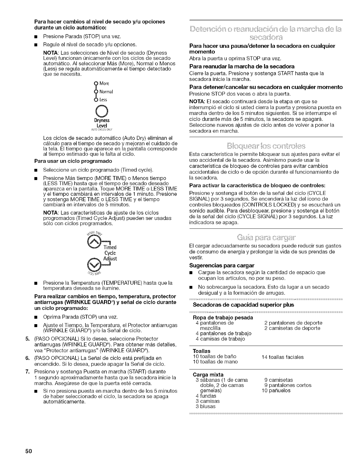
5,
6,
7.
Para hacer cambios al nivel de secado y/u opciones
durante un ciclo autornatico:
Presione Parada (STOP) una vez.
Regule el nivel de secado y/u opciones.
NOTA: Las selecciones de Nivel de secado (Dryness
Level) funcionan Qnicamente con los ciclos de secado
automatico. AI seleccionar Mas (More), Normal o Menos
(Less) se regula automaticamente el tiempo detectado
que se necesita.
More
Normal
Less
©
Dryness
Level
AUTO_YCLESONLY
Los ciclos de secado automatico (Auto Dry) eliminan el
calculo para el tiempo de secado y mejoran el cuidado de
la tela. El tiempo que aparece en la pantalla corresponde
al tiempo estimado que le falta al ciclo.
Para usar un ciclo programado
Seleccione un ciclo programado (Timed cycle).
Presione Mas tiempo (MORE TIME) o Menos tiempo
(LESS TIME) hasta que el tiempo de secado deseado
aparezca en la pantalla. Toque MORE TIME o LESS TIME
y el tiempo cambiara en intervalos de 1 minuto. Presione
y sostenga MORE TIME o LESS TIME y el tiempo
cambiara en intervalos de 5 minutos.
NOTA: Las caracter(sticas de ajuste de los ciclos
progromados (Timed Cycle Adjust) pueden ser usadas
s61o con ciclos programados.
Cyc(e
• Presione la Temperatura (TEMPERATURE) hasta que la
temperatura deseada se ilumine.
Para realizar cambies en tiempo, temperatura, protector
antiarrugas (WRINKLE GUARD ®)y serial de ciclo durante
un ciclo programado:
• Optima Parada (STOP) una vez.
• Ajuste el Tiempo, la Temperatura, el Protector antiarrugas
(WRINKLE GUARD _)y/o la SeSal de ciclo.
(PASO OPCIONAL) Si Io desea, seleccione Protector
antiarrugas (WRINKLE GUARD_). Para obtener mas detalles,
vea "Protector antiarrugas" (WRINKLE GUARD®).
(PASO OPCIONAL) La Serial de ciclo esta prefijada en
encendido. Si Io desea, puede apagar la SePal de ciclo.
Presione y sostenga Puesta en marcha (START) durante
1 segundo aproximadamente hasta que la secadora inicie la
marcha. Asegt_rese de que la puerta este cerrada.
• Si no presiona puesta en marcha dentro de los 5 minutes
de haber seleccionado el ciclo, la secadora se apaga
automaticamente.
Para hacer una pausa/detener la secadora en cualquier
momento
Abra la puerta u oprima STOP una vez.
Para reanudar la marcha de la secadora
Cierre la puerta. Presione y sostenga STARThasta que la
secadora inicie la marcha.
Para detener/cancelar su secadora en cualquier momento
Presione STOP dos veces o abra la puerta.
NOTA: El secado continuara desde la etapa en que se
interrumpi6 el ciclo si usted cierra la puerta y presiona puesta en
marcha dentro de los 5 minutes siguientes. Si se interrumpe el
ciclo durante mas de 5 minutes, la secadora se apagara.
Seleccione nuevos ajustes de ciclo antes de volver a poner la
secadora en marcha.
Esta caracteristica le permite bloquear sus ajustes para evitar el
uso accidental de la secadora. Asimismo puede usar la
caracteristica de bloqueo de controles para evitar cambios
accidentales de ciclo o de opci6n durante el funcionamiento de
la secadora.
Para activar la caracteristica de bloqueo de controles:
Presione y sostenga el bot6n de la sepal del ciclo (CYCLE
SIGNAL) per 3 segundos. Se encendera la luz del icono de
controles bloqueados (CONTROLS LOCKED) y se escuchara un
sonido audible. Para desbloquear, presione y sostenga el bot6n
de la sepal del ciclo (CYCLE SIGNAL) pot 3 segundos. La luz
indicadora se apaga.
El cargar adecuadamente su secadora puede reducir sus gastos
de consume de energia y prolongar la vida de sus prendas de
vestir.
Sugerencias para cargar
• Cargue la secadora segL_nla cantidad de espacio que
ocupan los artfculos, no per su peso.
• No sobrecargue la secadora. Esto da lugar a un secado
desigual y a la formaci6n de arrugas.
Secadoras de capacidad superior plus
Ropa de trabajo pesada
4 pantalones de 2 pantalones de deporte
mezclilla 2 camisetas de deporte
4 pantalones de trabajo
4 camisas de trabajo
Toallas
10 toallas de ba_o 14 toallas faciales
10 toallas de mane
Carga mixta
3 sabanas (1 de cama 9 camisetas
doble, 2 de camas 9 pantalones cortos
gemelas) 10 pa_uelos
4 fundas
3 camisas
3 blusas
50
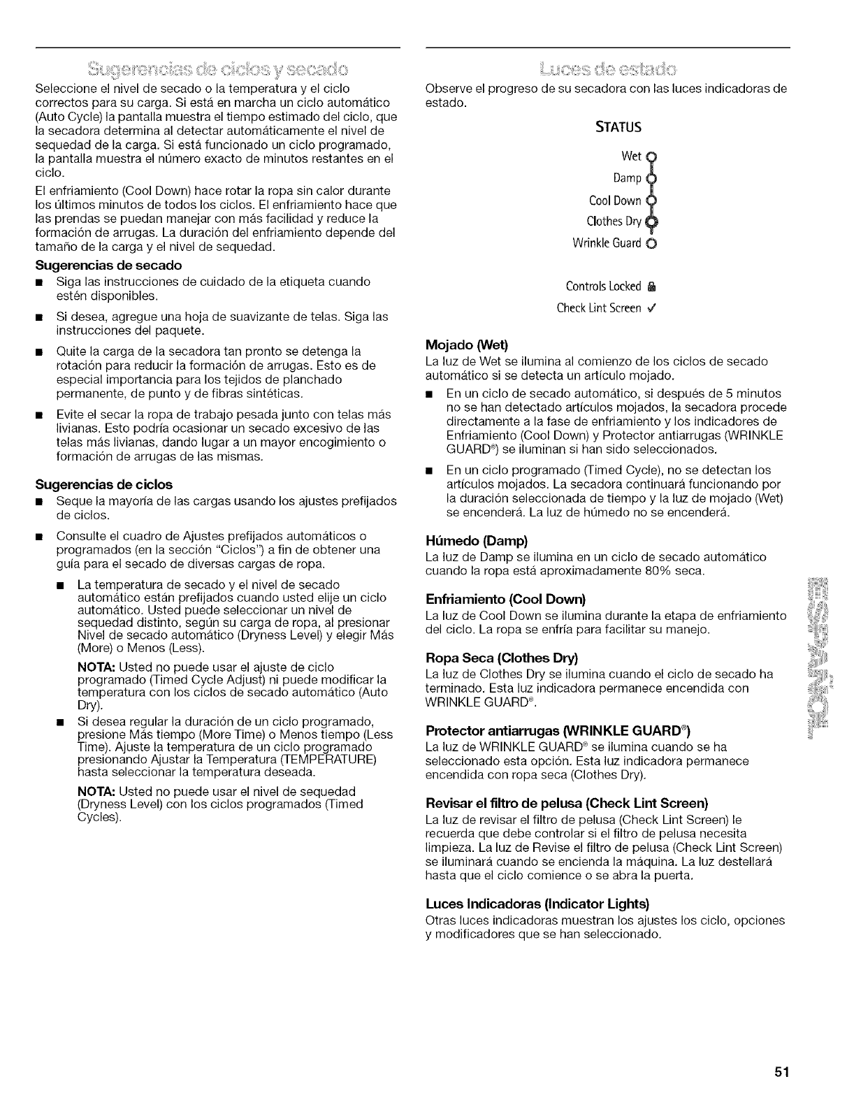
_:i:ii!ili_iiJJ!!iii_,_i!!!_!!,_ii_,i:::?_iii%3iii,;ili!:iilS!;_it,_i!i_i!!!¸C:iii,C!/OSi!i_i_'¸!%:!i!!_C_ii!i!i_i_i:::i_O
Seleccione el nivel de secado o la temperatura y el ciclo
correctos para su carga. Siesta en marcha un ciclo automatico
(Auto Cycle) la pantalla muestra el tiempo estimado del ciclo, que
la secadora determina al detectar automaticamente el nivel de
sequedad de la carga. Siesta funcionado un ciclo programado,
la pantalla muestra el nQmero exacto de minutos restantes en el
ciclo.
El enfriamiento (Cool Down) hace rotar la ropa sin calor durante
los QItimos minutes de todos los ciclos. El enfriamiento hace que
las prendas se puedan manejar con mas facilidad y reduce la
formaci6n de arrugas. La duraci6n del enfriamiento depende del
tamafio de la carga y el nivel de sequedad.
Sugerencias de secado
• Siga las instrucciones de cuidado de la etiqueta cuando
esten disponibles.
• Si desea, agregue una hoja de suavizante de telas. Siga las
instrucciones del paquete.
Quite la carga de la secadora tan pronto se detenga la
rotaci6n para reducir la formaci6n de arrugas. Esto es de
especial importancia para los tejidos de planchado
permanente, de punto y de fibras sinteticas.
Evite el secar la ropa de trabajo pesada junto con telas mas
livianas. Esto podria ocasionar un secado excesivo de las
telas mas livianas, dando lugar a un mayor encogimiento o
formaci6n de arrugas de las mismas.
Sugerencias de ciclos
• Sequela mayoria de las cargas usando los ajustes prefijados
de ciclos.
• Consulte el cuadro de Ajustes prefijados automaticos o
programados (en la secci6n "Ciclos") a fin de obtener una
guia para el secado de diversas cargas de ropa.
• La temperatura de secado y el nivel de secado
automatico estan prefijados cuando usted elije un ciclo
automatico. Usted puede seleccionar un nivel de
sequedad distinto, segQn su carga de ropa, al presionar
Nivel de secado automatico (Dryness Level) y elegir Mas
(More) o Menos (Less).
NOTA: Usted no puede usar el ajuste de ciclo
programado (Timed Cycle Adjust) ni puede modificar la
temperatura con los ciclos de secado automatico (Auto
Dry).
• Si desea regular la duraci6n de un ciclo programado,
presione Mas tiempo (More Time) o Menos tiempo (Less
Time). Ajuste la temperatura de un ciclo programado
presionando Ajustar la Temperatura (TEMPERATURE)
hasta seleccionar la temperatura deseada.
NOTA: Usted no puede usar el nivel de sequedad
(Dryness Level) con los ciclos programados (Timed
Cycles).
Observe el progreso de su secadora con las luces indicadoras de
estado.
STATUS
wet
Damp?
Cool Down ?
ClothesDry 9
Wrinkle Guard0
ControlsLocked
CheckLint Screen,/
Mojado (Wet)
La luz de Wet se ilumina al comienzo de los ciclos de secado
automatico si se detecta un articulo mojado.
• En un ciclo de secado automatico, si despues de 5 minutos
no se han detectado articulos mojados, la secadora procede
directamente a la fase de enfriamiento y los indicadores de
Enfriamiento (Cool Down) y Protector antiarrugas (WRINKLE
GUARD _) se iluminan si han side seleccionados.
En un ciclo programado (Timed Cycle), no se detectan los
articulos mojados. La secadora continuara funcionando por
la duraci6n seleccionada de tiempo y la luz de mojado (Wet)
se encender& La luz de hQmedo no se encender&
Ht_medo (Damp)
La luz de Damp se ilumina en un ciclo de secado automatico
cuando la ropa esta aproximadamente 80% seca.
Enfriamiento (Cool Down)
La luz de Cool Down se ilumina durante la etapa de enfriamiento
del ciclo. La ropa se enfria para facilitar su manejo.
Ropa Seca (Clothes Dry)
La luz de Clothes Dry se ilumina cuando el ciclo de secado ha
terminado. Esta luz indicadora permanece encendida con
WRINKLE GUARD ®.
Protector antiarrugas (WRINKLE GUARD e_)
La luz de WRINKLE GUARD _ se ilumina cuando se ha
seleccionado esta opci6n. Esta luz indicadora permanece
encendida con ropa seca (Clothes Dry).
Revisar el filtro de pelusa (Check Lint Screen)
La luz de revisar el filtro de pelusa (Check Lint Screen) le
recuerda que debe controlar si el filtro de pelusa necesita
limpieza. La luz de Revise el filtro de pelusa (Check Lint Screen)
se iluminara cuando se encienda la maquina. La luz destellara
hasta que el ciclo comience o se abra la puerta.
Luces Indicadoras (Indicator Lights)
Otras luces indicadoras muestran los ajustes los ciclo, opciones
y modificadores que se han seleccionado.
51
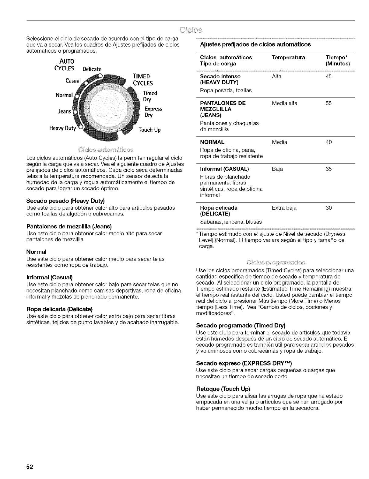
Seleccione el ciclo de secado de acuerdo con el tipo de carga
que va a secar. Vea los cuadros de Ajustes prefijados de ciclos
automaticos o programados.
AUTO
CYCLES Delicate
TIMED
Casual CYCLES
Normal Timed
Dry
.leans Express
Dry
HeavyDuty TouchUp
Los ciclos automaticos (Auto Cycles) le permiten regular el ciclo
segQn la carga que va a secar. Vea el siguiente cuadro de Ajustes
prefijados de ciclos automaticos. Cada ciclo seca determinadas
telas a la temperatura recomendada. Un sensor detecta la
humedad de la carga y regula automaticamente el tiempo de
secado para Iograr un secado 6ptimo.
Secado pesado (Heavy Duty)
Use este ciclo para obtener calor alto para articulos pesados
come toallas de algod6n o cubrecamas.
Pantalones de mezclilla (Jeans)
Use este ciclo para obtener calor medic alto para secar
pantalones de mezclilla.
Normal
Use este ciclo para obtener calor medic para secar telas
resistentes come ropa de trabajo.
Informal (Casual)
Use este ciclo para obtener calor bajo para secar telas que no
necesitan planchado como camisas deportivas, ropa de oficina
informal y mezclas de planchado permanente.
Ropa delicada (Delicate)
Use este ciclo para obtener calor extra bajo para secar fibras
sinteticas, tejidos de punto lavables y de acabado inarrugable.
Ajustes prefijados de ciclos automaticos
Ciclos automaticos Temperatura Tiempo*
Tipo de carga (Minutos)
Secado intenso Alta 45
(HEAVY DUTY)
Ropa pesada, toallas
PANTALONES DE
MEZCLILLA
(JEANS)
Pantalones y chaquetas
de mezclilla
Media alta 55
NORMAL Media
Ropa de oficina, pana,
ropa de trabajo resistente
4O
Informal (CASUAL)
Fibras de planchado
permanente, fibras
sinteticas, ropa de oficina
informal
Baja 35
Ropa delicada Extra baja
(DELICATE)
Sabanas, lenceria, blusas
3O
*Tiempo estimado con el ajuste de Nivel de secado (Dryness
Level) (Normal). El tiempo variara segQn el tipo y tamaho de
carga.
Use los ciclos programados (Timed Cycles) para seleccionar una
cantidad especifica de tiempo de secado y temperatura de
secado. AI seleccionar un ciclo programado, la pantalla de
Tiempo estimado restante (Estimated Time Remaining) muestra
el tiempo real restante del ciclo. Usted puede cambiar el tiempo
real del ciclo al presionar Mas tiempo (More Time) o Menos
tiempo (Less Time). Vea "Cambio de ciclos, opciones y
modificadores".
Secado programado ('rimed Dry}
Use este ciclo para terminar el secado de articulos que todavia
estan hL_medos despues de un ciclo de secado automatico. El
secado programado es tambien Qtil para secar articulos pesados
y voluminosos como cubrecamas y ropa de trabajo.
Secado expreso (EXPRESS DRY TM)
Use este ciclo para secar cargas pequehas o cargas que
necesitan un tiempo de secado corto.
Retoque (Touch Up)
Use este ciclo para alisar las arrugas de ropa que ha estado
empacada en una valija o articulos que se han arrugado per
haber permanecido mucho tiempo en la secadora.
52
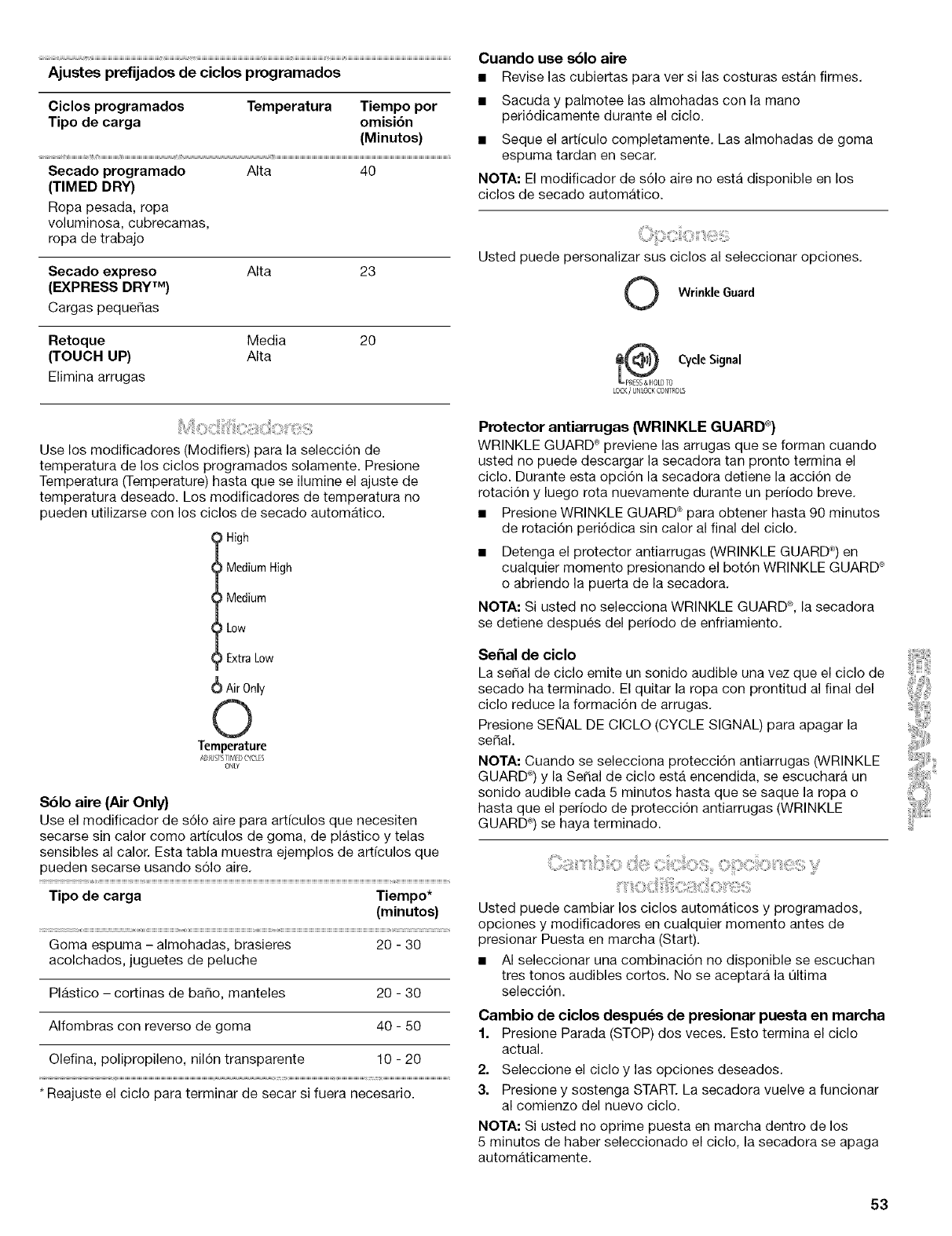
Ajustes prefijados de ciclos programados
Ciclos programados Temperatura Tiempo por
Tipo de carga omisi6n
(Minutos)
Secado programado AIta 40
(TIMED DRY)
Ropa pesada, ropa
voluminosa, cubrecamas,
ropa de trabajo
Secado expreso
(EXPRESS DRY TM)
Cargas pequer_as
Alta 23
Retoque Media
(TOUCH UP) AIta
Elimina arrugas
2O
Use los modificadores (Modifiers) para la selecci6n de
temperatura de los ciclos programados solamente. Presione
Temperatura (Temperature) hasta que se ilumine el ajuste de
temperatura deseado. Los modificadores de temperatura no
pueden utilizarse con los ciclos de secado automatico.
High
Medium High
Medium
_Low
Extra Low
(_ Air0nly
0
Temperature
A_]J/J_T'_TIMED( YC[;S
ONLY
S61o aire (Air Only)
Use el modificador de s61o aire para articulos que necesiten
secarse sin calor como articulos de goma, de plastico y telas
sensibles al calor. Esta tabla muestra ejemplos de art[culos que
pueden secarse usando s61o aire.
Tipo de carga Tiempo*
(minutos)
Goma espuma - almohadas, brasieres 20 - 30
acolchados, juguetes de peluche
Plastico - cortinas de baSo, manteles 20 - 30
AIfombras con reverso de goma 40 - 50
Olefina, polipropileno, nil6n transparente 10 -20
* Reajuste el ciclo para terminar de secar si fuera necesario.
Cuando use sblo aire
•Revise las cubiertas para ver si las costuras estan firmes.
• Sacuda y palmotee las almohadas con la mane
peri6dicamente durante el ciclo.
• Seque el articulo completamente. Las almohadas de goma
espuma tardan en secar.
NOTA: El modificador de s61o aire no esta disponible en los
ciclos de secado automatico.
Usted puede personalizar sus ciclos al seleccionar opciones.
O Wrinkle Guard
Cyde Signal
LOCK/UNLOCKCONTROLS
Protector antiarrugas (WRINKLE GUARD _)
WRINKLE GUARD ®previene las arrugas que se forman cuando
usted no puede descargar la secadora tan pronto termina el
ciclo. Durante esta opci6n la secadora detiene la acci6n de
rotaci6n y luego rota nuevamente durante un per[odo breve.
• Presione WRINKLE GUARD _ para obtener hasta 90 minutos
de rotaci6n peri6dica sin calor al final del ciclo.
• Detenga el protector antiarrugas (WRINKLE GUARD ®)en
cualquier momento presionando el bot6n WRINKLE GUARD _
o abriendo la puerta de la secadora.
NOTA: Si usted no selecciona WRINKLE GUARD _, la secadora
se detiene despues del periodo de enfriamiento.
Sehal de ciclo
La seSal de ciclo emite un sonido audible una vez que el ciclo de
secado ha terminado. El quitar la ropa con prontitud al final del
ciclo reduce la formaci6n de arrugas.
Presione SEI_IAL DE CICLO (CYCLE SIGNAL) para apagar la
seSal.
NOTA: Cuando se selecciona protecci6n antiarrugas 0NRINKLE
GUARD ®)y la SeSal de ciclo esta encendida, se escuchara un
sonido audible cada 5 minutos hasta que se saque la ropa o
hasta que el per[odo de protecci6n antiarrugas (WRINKLE
GUARD ®)se haya terminado.
Usted puede cambiar los ciclos automaticos y programados,
opciones y modificadores en cualquier momento antes de
presionar Puesta en marcha (Start).
• AI seleccionar una combinaci6n no disponible se escuchan
tres tonos audibles cortos. No se aceptara la Qltima
selecci6n.
Cambio de ciclos despu_s de presionar puesta en marcha
1. Presione Parada (STOP) dos veces. Esto termina el ciclo
actual.
2. Seleccione el ciclo y las opciones deseados.
3. Presione y sostenga START. La secadora vuelve a funcionar
al comienzo del nuevo ciclo.
NOTA: Si usted no oprime puesta en marcha dentro de los
5 minutos de haber seleccionado el ciclo, la secadora se apaga
automaticamente.
53
Cambio de opciones y modificadores despu_s de
presionar puesta en marcha
Usted puede cambiar una opci6n o modificador en cualquier
momento antes de que comience la opci6n o modificador
seleccionado.
1. Presione STOP una vez.
2. Seleccione la nueva opci6n y/o modificador.
3. Presione y sostenga START para continuar el ciclo.
NOTA: Si accidentalmente presiona parada dos veces, el
programa se despejara y la secadora se apagar& Vuelva a iniciar
el proceso de selecci6n.
El estante de secado fue embalado en su lugar dentro de su
secadora. Retffelo y deshagase del material de embalaje antes
de usarlo.
Use el estante no termico de la secadora TUMBLE FREETM para
articulos que usted no quiere secar con rotaci6n, como son
sueteres.
Para usar el estante de la secadora
No quite el filtro de pelusa.
1. Abra la puerta de la secadora.
A
A. Borde anterior
2. Coloque el estante de la secadora dentro del tambor de la
secadora, colocando el alambre posterior sobre la saliente
del panel posterior del interior de la secadora. Empuje hacia
abajo sobre el borde anterior del estante de la secadora para
asegurarlo sobre el filtro de pelusa.
A
A. Borde anterior del estante de la secadora
B. Panel posterior de la secadora
3. Ponga los articulos mojados sobre el estante de secado. Deje
espacio entre los artfculos para que el aire pueda Ilegar a
todas las superficies.
NOTA: No permita que los artfculos cuelguen del borde del
estante de secado.
4. Cierre la puerta.
5. Optima el bot6n de suministro de energia (POWER).
6. Seleccione un ciclo programado de tiempo y de temperatura
(vea el siguiente cuadro). Los artfculos que contengan
espuma, hule o plastico deben secarse en un tendedero o
usando el ajuste de temperatura de s61o aire (Air Only).
7. Usted puede seleccionar el tiempo del ciclo, presionando los
botones de mas tiempo (MORE TIME) o menos tiempo (LESS
TIME). Vuelva a fijar el tiempo para terminar el secado, si es
necesario. Consulte el cuadro a continuaci6n.
8. Presione (y sostenga) el botdn de puesta en marcha (START)
(por aproximadamente 3 segundos).
NOTA: Usted debe quitar el estante para un secado normal. No
use ciclos automaticos con el estante de la secadora.
Este cuadro muestra ejemplos de articulos que pueden secarse
en el estante y el tiempo sugerido de secado, ciclo y el ajuste de
temperatura. El tiempo real de secado dependera de la cantidad
de humedad en la carga.
Secado con estante Ajuste Temp. Tiempo*
Su6teres de lana Ciclos Baja 60
Darles la forma original y progra- (Low)
colocarlos extendidos sobre mados
el estante de secado.
Juguetes de peluche o Ciclos Baja
almohadas progra- (Low)
Rellenos de fibras de mados
algod6n o poliester
6O
Juguetes de peluche o Ciclos S61o
almohadas progra- aire
Rellenos con hule espuma mados (sin
calor)
9O
Zapatos tenis o zapatos Ciclos S61o 90
de Iona progra- aire
mados (sin
calor)
*(Minutos) Vuelva a fijar el ciclo para terminar el secado, si es
necesario.
54
CUIDADO DE LA SECADORA
iii ii_iiii_i_ii:il;i_ii_!!:::!%iii!!ii_iiii:::ii_i!i?_iI_Ji,i!iiiiii_!_i!i:ii_¸¸__i::;iiiiOiiii_!i:il;ii,i_?_i;i!iXi!il;;i_!_;i!!!iiii,i,'ii!ii!!!!J_i:ii!:?O;ii%i:i:::iiiiO_ili!_J_'!!_
Mantenga el Area donde esta la secadora despejada y libre de
art[culos que pudieran obstruir el flujo de aire para la combusti6n
y la ventilaci6n.
Peligro de Explosi6n
Mantenga los matedames y vapores infmamabmee,come
la gasoHna, mejos de la eecadora.
Comoque ia secadora a un m_nime de 46 cm eobre
emp[so para la instaiac[6n en un garaje.
No seguir estas instrucciones puede ocasionar
la muerte, explosi6n o incendio.
Limpieza segun la necesidad
Los residues de detergente de lavanderia y suavizante de telas
pueden acumularse en el filtro de pelusa. Esta acumulaci6n
puede ocasionar tiempos de secado mas prolongados para su
ropa, o hacer que la secadora se detenga antes que su carga
este completamente seca. Si la pelusa se cae del filtro cuando
este esta en la secadora, es probable que el filtro este obstruido.
Limpie el filtro de pelusa con un cepillo de nailon cada 6 meses o
con mas frecuencia si se obstruye debido a la acumulaci6n de
residues.
Para lavar
1. Quite la pelusa del filtro enrollandola con sus dedos.
2. Moje ambos lades del filtro de pelusa con agua caliente.
3. Moje un cepillo de nailon con agua caliente y detergente
I[quido. Refriegue el filtro de pelusa con el cepillo para quitar
la acumulaci6n de residues.
Limpieza de cada carga
El filtro de pelusa esta Iocalizado en la abertura de la puerta de la
secadora. El panel de control tiene una luz indicadora para
recordarle que tiene que limpiar el filtro de pelusa antes de cada
carga. Un filtro obstruido con pelusa puede aumentar el tiempo
de secado.
Para limpiar
1. Jale el filtro de pelusa en sentido recto hacia arriba. Quite la
pelusa del filtro enrollandola con sus dedos. No enjuague ni
lave el filtro para quitar la pelusa. La pelusa mojada es dif[cil
de quitar.
2. Empuje el filtro de pelusa firmemente de vuelta en su lugar.
IMPORTANTE:
• No ponga a funcionar la secadora con un filtro de pelusa
flojo, da_ado, obstruido o sin el. El hacerlo puede causar un
sobrecalentamiento y da_ar tanto la secadora come la ropa.
AIgunas toallas hechas de fibras sinteticas y fibras naturales
(mezclas de poliester y algod6n) pueden soltar mas pelusa
que otras toallas, dando lugar a que el filtro de pelusa de su
secadora se Ilene con mas rapidez. AsegQrese de quitar la
pelusa del filtro de pelusa antes y despues de secar toallas
nuevas.
• Sial quitar la pelusa del filtro, esta cae en la secadora, revise
la capota de ventilaci6n y quite la pelusa. Vea "Requisites de
ventilaci6n".
4. Enjuague el filtro con agua caliente.
5. Seque meticulosamente el filtro de pelusa con una toalla
limpia. Vuelva a colocar el filtro en la secadora.
Para limpiar el tambor de la secadora
1. Haga una pasta con un detergente de lavanderia en polvo y
agua tibia.
2. Aplique la pasta a un pa_o suave.
O
Aplique al Area manchada un producto de limpieza
domestico I[quido, no inflamable y fr6telo con un pa_o suave
hasta quitar todo el exceso de tinte y manchas.
3. Limpie el tambor meticulosamente con un pa_o hQmedo.
4. Ponga a funcionar la secadora con una carga de ropa limpia
o toallas para secar el tambor.
NOTA: Las prendas que contienen tintes dester_ibles, tales come
los pantalones de mezclilla o articulos de algod6n de colores
vivos, pueden te_ir el interior de la secadora. Estas manchas no
da_an su secadora y no mancharan las cargas de ropa futuras.
Seque al reves los articulos que desti_en para evitar la
transferencia de tintes.
55
En el interior del gabinete de la secadora
SegOn el uso de la secadora, se debe quitar la pelusa cada
2 ares, o con mas frecuencia. La limpieza debera efectuarla
una persona calificada.
En el ducto de escape:
La pelusa debe ser quitada cada 2 ares, o con mas frecuencia,
de acuerdo con el uso de la secadora.
Cuidado para las vacaciones
Ponga la secadora a funcionar s61o cuando este en casa. Siva a
salir de vacaciones o no va a usar su secadora per un tiempo
prolongado, usted debera:
1. Desenchufar la secadora o desconectar el suministro de
energ[a.
2. Limpiar el filtro de pelusa. Vea "Limpieza del filtro de pelusa".
Cuidado para la mudanza
Para secadoras conectadas al cable de suministro
el_ctrico:
1. Desenchufe el cable de suministro de energia.
2. AsegQrese de que las patas niveladoras esten fijas en la base
de la secadora.
3. Use cinta adhesiva para asegurar la puerta de la secadora.
PeHgro de Choque E}ectrico
Desconecte e_ suministro de energ_a antes de dar_e
mantenim[ento,
VueIva a colocar todos los componentes y paneies
antes de hacerlo funcionar.
No seguir estas instrucciones puede ocasionar
la rnuerte o cheque e}ectrico,
Para escadoras con cableado directo:
1. Desconecte el suministro de energfa.
2. Desconecte el cableado.
3. AsegQrese de que las patas niveladoras esten fijas en la base
de la secadora.
4. Use cinta adhesiva para asegurar la puerta de la secadora.
56
SOLUCION DE PROBLEMAS
Pruebe primero las soluciones aqui sugeridas y posiblemente se evite el costo de una visita de servicio t_cnico...
La secadora no funciona
&Hay un fusible de la casa fundido o se dispar6 el
cortacircuitos?
Es posible que la secadora tenga 2 fusibles o cortacircuitos,
AsegUrese de que ambos fusibles esten intactos y ajustados,
o de que ambos cortacircuitos no se hayan disparado.
Reemplace el fusible o reposicione el cortacircuitos. Si el
problema continua, Name a un electricista.
&Es el suministro de energia el correcto?
Las secadoras electricas requieren un suministro electrico de
240 voltios. Verifique con un electricista calificado.
&Se us6 un fusible regular?
Use un fusible retardador.
&Est_i cerrada con firmeza la puerta de la secadora?
&Se oprimi6 con firmeza el botbn de Puesta en marcha?
Optima y sostenga durante 1 segundo.
Sin calor
&Hay un fusible de la casa fundido o se dispar6 el
cortacircuitos?
El tambor quizas rote pero sin calor. Las secadoras electricas
utilizan 2 fusibles o disyuntores, Reemplace el fusible o
reposicione el cortacircuitos. Si el problema continua, Name a
un electricista,
Sonidos raros
&Ha estado la secadora sin uso por una temporada?
Si no se ha usado la secadora per una temporada, es posible
que se escuche un sonido fuerte durante los primeros
minutes de funcionamiento,
&Hay una moneda, bot6n o sujetapapeles entre el tambor
y la parte frontal o trasera de la secadora?
Revise los bordes frontales y traseros del tambor para
verificar si hay objetos peque_os. Limpie los bolsillos antes
del lavado.
&Estan las cuatro patas instaladas yest_i la secadora
nivelada de frente hacia atr_is y de lado a lado?
La secadora puede vibrar si no esta instalada
adecuadamente. Vea las Instrucciones de instalaci6n.
&Las prendas est_n enredadas o hechas un ovillo?
Si la carga esta hecha un ovillo, rebotara haciendo vibrar a la
secadora. Separe los artfculos de la carga y reinicie la
secadora,
La secadora muestra mensajes codificados
"PF" (corte de corriente), revise Io siguiente:
_,Se ha interrumpido el ciclo de secado per un corte de
corriente? Presione y sostenga Puesta en marcha (START)
para reanudar la marcha de la secadora,
•"E" C6digos de servicio t_cnico variables (El, E2, E3):
Llame solicitando servicio tecnico.
);;::)iq}!;i!7i}_
Las prendas no se secan satisfactoriamente, los
tiempos de secado son demasiado largos, la carga est&
demasiado caliente
•i.Esta el filtro de pelusa obstruido con pelusa?
El filtro de pelusa debe set limpiado antes de cada carga.
Peligro de tncendio
Use un ducto de escape de metal pesado,
No use un ducto de escape de pl&stico,
No use un ducto de escape de aluminio,
laNOmuerteseguir oeStaSincendio,instrucci°nespuede ocasionar
•_.Est_ obstruido con pelusa el ducto de escape o la
capota de ventilaci6n, restringiendo el flujo del aire?
Ponga a funcionar la secadora unos 5 a 10 minutes. Ponga
su mane debajo de la capota de ventilaci6n para verificar el
movimiento del aire, Si no Io siente, limpie la pelusa del
sistema de ventilaci6n o reemplace el ducto de escape con
uno de metal pesado o de metal flexible. Vea las
Instrucciones de instalaci6n,
_.Estan las hojas del suavizante de telas bloqueando la
rejilla?
Use Unicamente una hoja del suavizante de telas y Usela una
sola vez.
&Tiene el ducto de escape el largo correcto?
Controle el ducto de escape para verificar que no sea
demasiado largo o no de demasiadas vueltas. Una
ventilaci6n larga aumentara el tiempo de secado, Vea las
Instrucciones de instalaci6n.
•i.Es el diametro del ducto de escape del tama5o
correcto?
Use un material de ventilacidn de 4" (10,2 cm) de diametro,
57
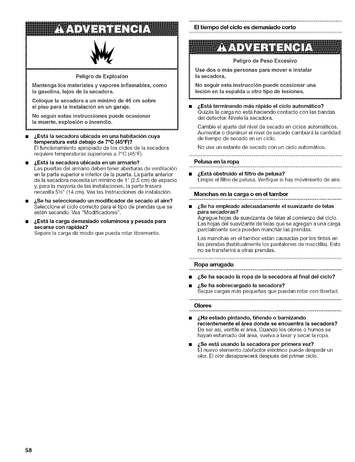
PeHgro de Expmosi6n
Mantenga los materiames y vapores infmamabiee, come
magasoiina, lejos de la secadora.
Comoque is eecadora a un m_nimo de 48 cm sobre
empiso para mainstaBaci6n en un garajeo
No seguir estae instruccienee puede ocasionar
mamuerte, e×pmeei6n e incendioo
i,Esta la secadora ubicada en una habitaci6n cuya
temperatura esta debajo de 7°0 (45°F)?
El funcionamiento apropiado de los ciclos de la secadora
requiere temperaturas superiores a 7°C (45°F).
i.Esta la secadora ubicada en un armario?
Las puertas del armario deben tener aberturas de ventilaci6n
en la parts superior e inferior de la puerta. La parts anterior
de la secadora necesita un minimo de 1" (2,5 cm) de espacio
y, para la mayorfa de las instalaciones, la parte trasera
necesita 51/2'' (14 cm). Vea las Instrucciones de instalaci6n.
• _,Se ha seleccionado un modificador de secado al aire?
Seleccione el ciclo correcto para el tips de prendas que se
esten secando, Vea "Modificadores".
• _,Est_ la carga demasiado voluminosa y pesada para
secarse con rapidez?
Separe ia carga de mode que pueda rotar libremente.
El tiempo del ciclo es demasiado corto
Pe_igro de Peso E×cesivo
Use dos o mas personas para mover e instalar
la eecadora,
No seguir esta instrucci6n puede ocssionar una
leei6n en la eepalda u otto tipo de _esioneeo
• &Esta terminando mas rapido el eiclo automatico?
Quizas la carga no esta haciendo contacto con las bandas
del detector. Nivele la secadora,
Cambie el ajuste del nivel de secado en ciclos automaticos.
Aumentar o disminuir el nivel de secado cambiara la cantidad
de tiempo de secado en un ciclo.
No use un estante de secado con un ciclo automatico.
Pelusa en la ropa
• &Esta obstruido el filtro de pelusa?
Limpie el filtro de pelusa, Verifique si hay movimiento de aire.
Manchas en la carga o en el tambor
•i,Se ha empleado adecuadamente el suavizante de telas
para secadoras?
Agregue hojas de suavizante de telas al comienzo del ciclo,
Las hojas del suavizante de telas que se agregan a una carga
parcialmente seca pueden manchar las prendas.
Las manchas en el tambor estan causadas per los tintes en
las prendas (habitualmente los pantalones de mezclilla), Esto
no se transferira a otras prendas,
Ropa arrugada
• &Se ha sacado la ropa de la secadora al final del ciclo?
• &Se ha sobrecargado la secadora?
Seque cargas mas pequer_as que puedan rotar con libertad.
Olores
• &Ha estado pintando, ti5endo o barnizando
recientemente el area donde se encuentra la secadora?
De ser asi, ventile el area, Cuando los olores o humos se
hayan esfumado del Area, vuelva a lavar y secar la ropa.
• &Se est_ usando la secadora per primera vez?
El nuevo elemento calefactor eiectrico puede despedir un
olor. El olor desaparecera despues del primer ciclo,
58

59
Your Home
For repair-in your home-of all major brand appliances,
lawn and garden equipment, or heating and cooling systems,
no matter who made it, no matter who sold it!
For the replacement parts, accessories and
owner's manuals that you need to do-it-yourself.
For Sears professional installation of home appliances
and items like garage door openers and water heaters.
iiiiiiiiiiiiiiiiii
1-800-4-MY-HOME ®(1-800-469-4663)
On,an t, eastorni0ht US andOanada/
www.sears.com www.sears.ca
Our Home
For repair of carry-in items like vacuums, lawn equipment,
8572743 . TM SM •7/05
® Registered Trademark /Trademark /Serwce Mark of Sears Brands, LLC Printed in U.S.A,
, TM SM , ,
© 2005 Sears Brands, LLC ® Marca Reg_strada /Marca de Comercio /Marca de Serwc_o de Sears Brands, LLC Impreso en EE. UU,
