Kenmore 153331350 User Manual WATER HEATER Manuals And Guides 1304032L
User Manual: Kenmore 153331350 153331350 KENMORE WATER HEATER - Manuals and Guides View the owners manual for your KENMORE WATER HEATER #153331350. Home:Plumbing Parts:Kenmore Parts:Kenmore WATER HEATER Manual
Open the PDF directly: View PDF ![]() .
.
Page Count: 68
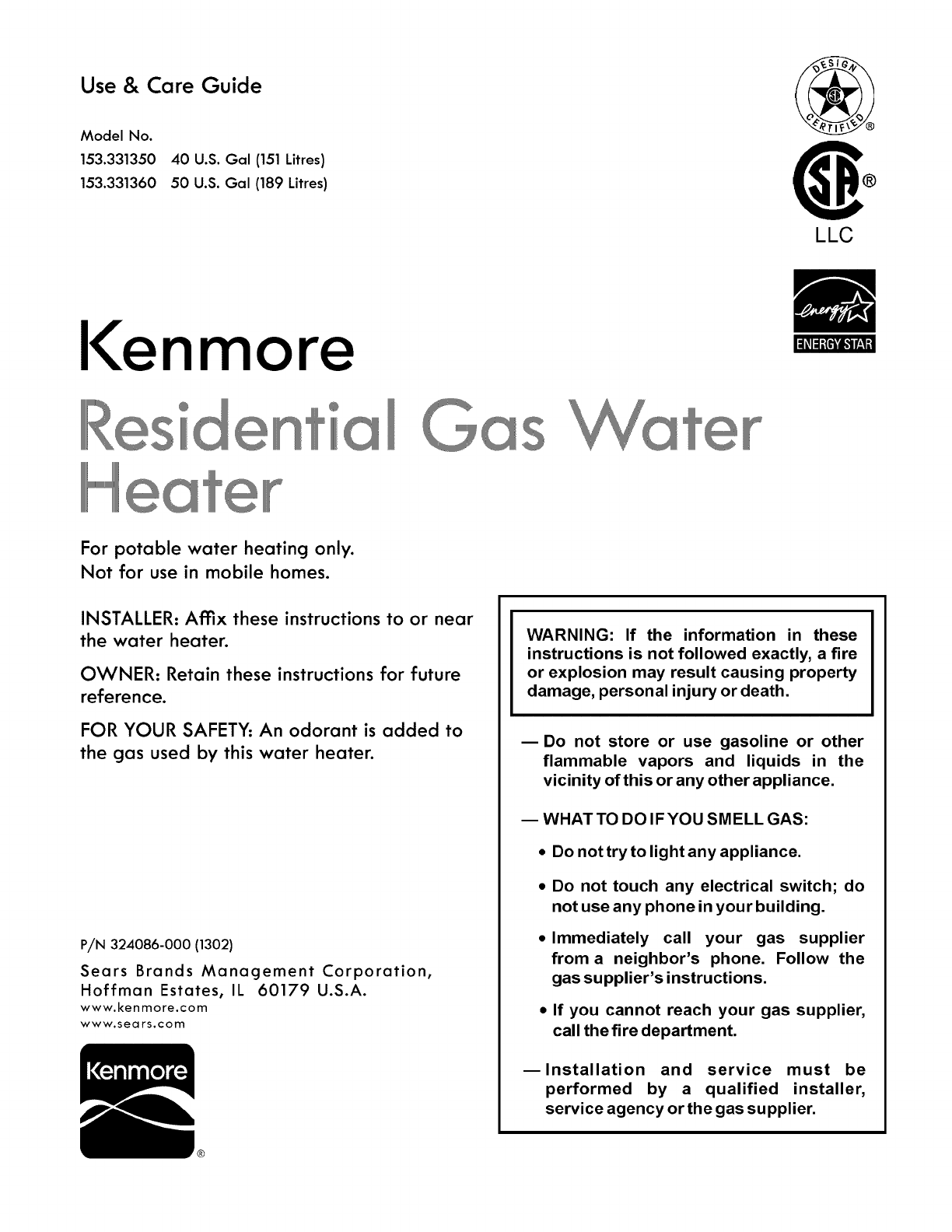
Use & Care Guide
Model No.
153.331350
153.331360
40 U.S. Gal (151 Litres)
50 U.S. Gal (189 Litres)
LLC
I<enmore lllillll{II'II_111LAll
°a
For potable water heating only.
Not for use in mobile homes.
INSTALLER: Affix these instructions to or near
the water heater.
OWNER: Retain these instructions for future
reference.
FOR YOUR SAFETY: An odorant is added to
the gas used by this water heater.
P/N 324086-000 (1302)
Sears Brands Management Corporation,
Hoffman Estates, IL 60179 U.S.A.
www.kenmore.com
www.sears.com
WARNING: If the information in these
instructions is not followed exactly, a fire
or explosion may result causing property
damage, personal injury or death.
mDo not store or use gasoline or other
flammable vapors and liquids in the
vicinity of this or any other appliance,
-- WHAT TO DO IF YOU SMELL GAS:
•Do not try to light any appliance.
•Do not touch any electrical switch; do
not use any phone in your building.
•Immediately call your gas supplier
from a neighbor's phone. Follow the
gas supplier's instructions.
•If you cannot reach your gas supplier,
call the fire department.
mlnstallation and service must be
performed by a qualified installer,
service agency or the gas supplier.
®

Your safety and the safety of others is extremely important in the installation, use and servicing of this water heater.
Many safety-related messages and instructions have been provided in this manual and on your own water heater to warn you
and others of a potential injury hazard. Read and obey all safety messages and instructions throughout this manual. It is very
important that the meaning of each safety message is understood by you and others who install, use or service this water
heater.
This is the safety alert symbol. It is used to alert you
to potential personal injury hazards. Obey all safety
messages that follow this symbol to avoid possible
injury or death.
__..-'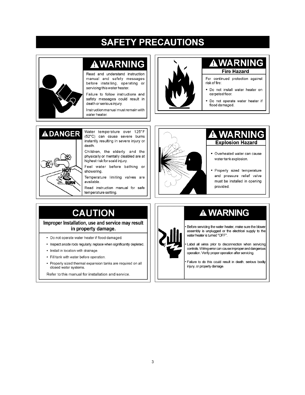
Read and understand instruction
manual and safety messages
before installing, operating or
servicing thiswater heater.
Failure to follow instructions and
safety messages could result in
death or serious injury.
Instruction manual must remain with
water heater.
Fire Hazard
For continued protection against
riskoffire:
•De not install water heater on
carpeted floor.
•Do not operate water heater if
flood damaged.
Water temperature over 125°F
(52°C) can cause severe burns
instantly resulting in severe injury or
death.
Children, the elderly and the
physically or mentally disabled are at
highest risk for scald injury.
Feel water before bathing or
showering.
Temperature limiting valves are
available.
Read instruction manual for safe
temperature setting.
ImproperInstallation,use and servicemay result
in property damage.
JExplosion Hazard
• Overheated water can cause
water tankexplosion.
• Properly sized temperature
and pressure relief valve
must be installed in opening
provided.
•Do not operate water heater if flood damaged.
•Inspect anode rods regularly, replace when significantly depleted.
•Install in location with drainage.
• Fill tank with water before operation.
•Properly sized thermal expansion tanks are required on all
closed water systems.
Refer to this manual for installation and service.
• Before servicing the water heater, make sure the bbwer
assembly is unplugged or the electrical supply to the
water heater istumed "OFF".
• Label all wires prior to disconnection when servicing
controls. Wiring error can cause improperand dangerous
operation. Verify proper operation after servicing.
• Failure to do this could res,ult in death, serious bedil_
injury, or property damage.

Breathing Hazard -Carbon Monoxide Gas
• Install vent system in accordance with codes.
•Do not operate water heater if flood damaged.
•For operation above 10,100' (3,079 m), ahigh
altitude orifice must be installed.
•Do not operate if soot buildup is present.
•Do not obstruct water heater air intake with
insulating jacket.
•Do not obstruct blower air intake.
•Do not place chemical vapor emitting products
near water heater.
•Gas and carbon monoxide detectors are
available.
•No vent damper installation is compatible with
this power vented water heater.
Breathing carbon monoxide can cause brain damage or death•
Always read and understand instruction manual.
Fire or Explosion Hazard
•Do not store or use gasoline or other flammable vapors
and liquids in the vicinity of this or any other appliance.
• Avoid all ignition sources if you smell gas.
• Do not expose water heater control to excessive gas
pressure.
• Use only gas shown on rating plate.
• Maintain required clearances to combustibles.
• Keep ignition sources away from faucets after extended
period of non-use.
Read instruction manual before ,_
installing, using or servicing
water heater.
Flammable Vapors
iq_uVapors from flammable
s may explode and
catch fire causing death or
severe burns.
Do not use or store
flammable products such as
gasoline, solvents or adhe-
sives in the same room or
area near the water heater.
Keep flammable products:
1. far away from heater,
2. in approved containers,
3. tightly closed and
4. out of children's reach.
Water heater has a main
burner and hot surface igniter.
The hot surface igniter:
1. can be triggered at any
time and
2. the hot surface will ignite
flammable vapors.
Vapors:
1. cannot be seen,
2. are heavier than air,
3. go a long way on the floor
and
4. can be carried from other
rooms to the the
electodes by air currents.
Installation: Do not install the water heater where flammable
products will be stored or used.
SAFE INSTALLATION, USE AND SERVICE 2
SAFETY PRECAUTIONS 3
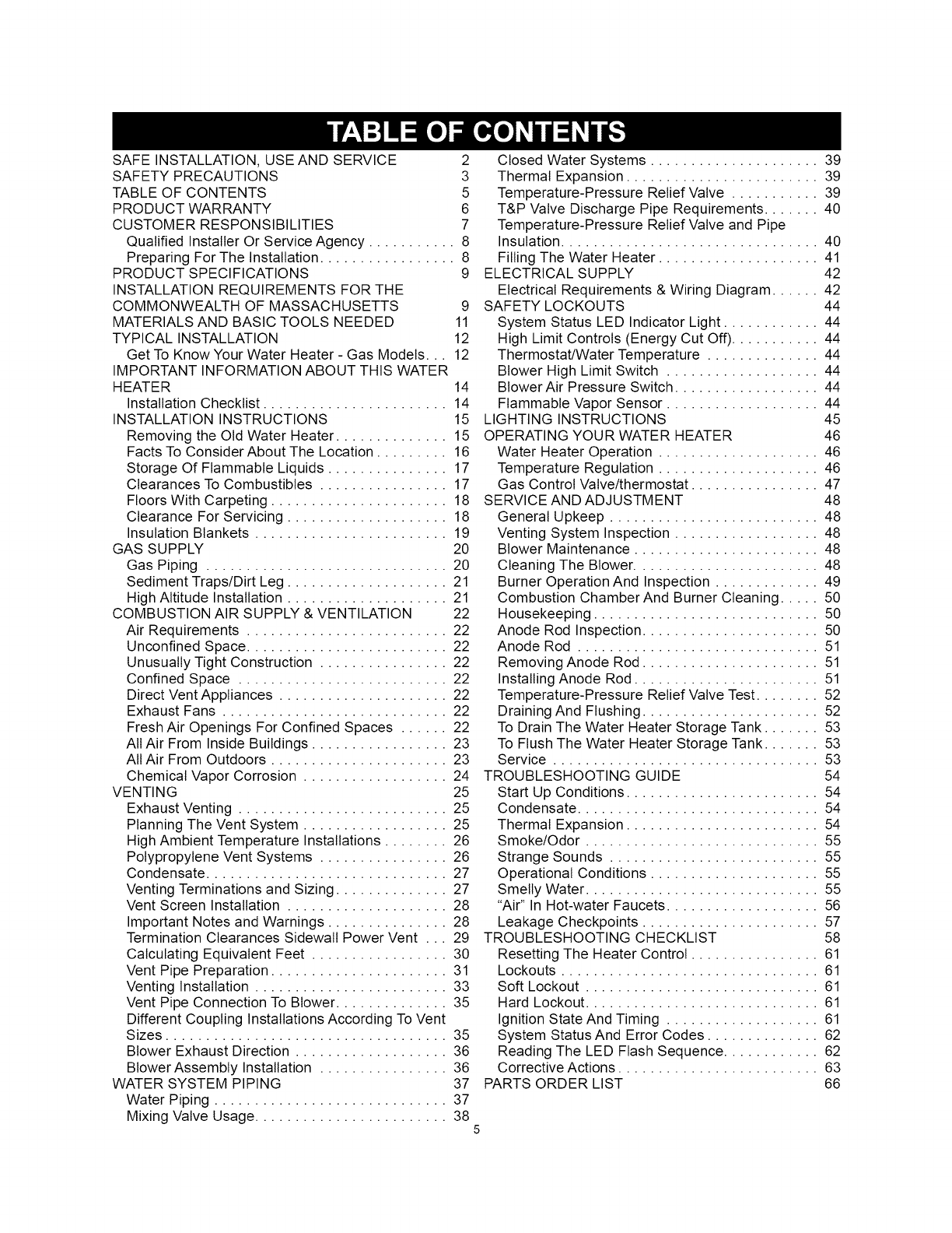
TABLE OF CONTENTS 5
PRODUCT WARRANTY 6
CUSTOMER RESPONSIBILITIES 7
Qualified Installer Or Service Agency ........... 8
Preparing For The Installation ................. 8
PRODUCT SPECIFICATIONS 9
INSTALLATION REQUIREMENTS FOR THE
COMMONWEALTH OF MASSACHUSETTS 9
MATERIALS AND BASIC TOOLS NEEDED 11
TYPICAL INSTALLATION 12
Get To Know Your Water Heater - Gas Models... 12
IMPORTANT INFORMATION ABOUT THIS WATER
HEATER 14
Installation Checklist ....................... 14
INSTALLATION INSTRUCTIONS 15
Removing the Old Water Heater .............. 15
Facts To Consider About The Location ......... 16
Storage Of Flammable Liquids ............... 17
Clearances To Combustibles ................ 17
Floors With Carpeting ...................... 18
Clearance For Servicing .................... 18
Insulation Blankets ........................ 19
GAS SUPPLY 20
Gas Piping .............................. 20
Sediment Traps/Dirt Leg .................... 21
High Altitude Installation .................... 21
COMBUSTION AIR SUPPLY & VENTILATION 22
Air Requirements ......................... 22
Unconfined Space ......................... 22
Unusually Tight Construction ................ 22
Confined Space .......................... 22
Direct Vent Appliances ..................... 22
Exhaust Fans ............................ 22
Fresh Air Openings For Confined Spaces ...... 22
All Air From Inside Buildings ................. 23
All Air From Outdoors ...................... 23
Chemical Vapor Corrosion .................. 24
VENTING 25
Exhaust Venting .......................... 25
Planning The Vent System .................. 25
High Ambient Temperature Installations ........ 26
Polypropylene Vent Systems ................ 26
Condensate .............................. 27
Venting Terminations and Sizing .............. 27
Vent Screen Installation .................... 28
Important Notes and Warnings ............... 28
Termination Clearances Sidewall Power Vent ... 29
Calculating Equivalent Feet ................. 30
Vent Pipe Preparation ...................... 31
Venting Installation ........................ 33
Vent Pipe Connection To Blower .............. 35
Different Coupling Installations According To Vent
Sizes ................................... 35
Blower Exhaust Direction ................... 36
Blower Assembly Installation ................ 36
WATER SYSTEM PIPING 37
Water Piping ............................. 37
Mixing Valve Usage ........................ 38
Closed Water Systems ..................... 39
Thermal Expansion ........................ 39
Temperature-Pressure Relief Valve ........... 39
T&P Valve Discharge Pipe Requirements ....... 40
Temperature-Pressure Relief Valve and Pipe
Insulation ................................ 40
Filling The Water Heater .................... 41
ELECTRICAL SUPPLY 42
Electrical Requirements & Wiring Diagram ...... 42
SAFETY LOCKOUTS 44
System Status LED Indicator Light ............ 44
High Limit Controls (Energy Cut Off) ........... 44
Thermostat/Water Temperature .............. 44
Blower High Limit Switch ................... 44
Blower Air Pressure Switch .................. 44
Flammable Vapor Sensor ................... 44
LIGHTING INSTRUCTIONS 45
OPERATING YOUR WATER HEATER 46
Water Heater Operation .................... 46
Temperature Regulation .................... 46
Gas Control Valve/thermostat ................ 47
SERVICE AND ADJUSTMENT 48
General Upkeep .......................... 48
Venting System Inspection .................. 48
Blower Maintenance ....................... 48
Cleaning The Blower ....................... 48
Burner Operation And Inspection ............. 49
Combustion Chamber And Burner Cleaning ..... 50
Housekeeping ............................ 50
Anode Rod Inspection ...................... 50
Anode Rod .............................. 51
Removing Anode Rod ...................... 51
Installing Anode Rod ....................... 51
Temperature-Pressure Relief Valve Test ........ 52
Draining And Flushing ...................... 52
To Drain The Water Heater Storage Tank ....... 53
To Flush The Water Heater Storage Tank ....... 53
Service ................................. 53
TROUBLESHOOTING GUIDE 54
Start Up Conditions ........................ 54
Condensate .............................. 54
Thermal Expansion ........................ 54
Smoke/Odor ............................. 55
Strange Sounds .......................... 55
Operational Conditions ..................... 55
Smelly Water ............................. 55
"Air" In Hot-water Faucets ................... 56
Leakage Checkpoints ...................... 57
TROUBLESHOOTING CHECKLIST 58
Resetting The Heater Control ................ 61
Lockouts ................................ 61
Soft Lockout ............................. 61
Hard Lockout ............................. 61
Ignition State And Timing ................... 61
System Status And Error Codes .............. 62
Reading The LED Flash Sequence ............ 62
Corrective Actions ......................... 63
PARTS ORDER LIST 66
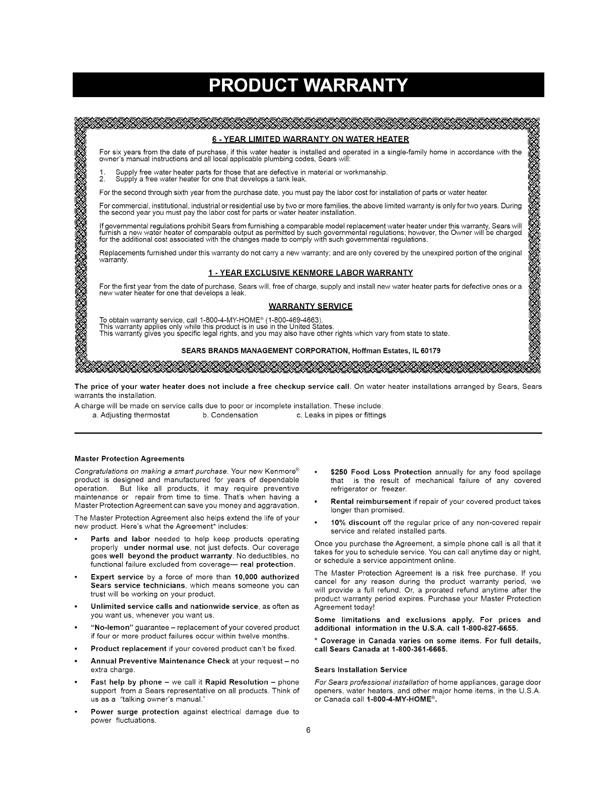
6 -YEAR LIMITED WARRANTY ON WATER HEATER
For six years from the date of purchase, if this water heater is installed and operated in asingle-family home in accordance with the
owner's manual instructions and all local applicable plumbing codes, Sears will:
. Supply free water heater parts for those that are defective in material or workmanship.
• Supply afree water heater for one that develops a tank leak.
For the second through sixth year from the purchase date, you must pay the labor cost for installation of parts or water heater.
For commercial, institutional, industrial or residential use by two or more families, the above limited warranty is only for two years. During
the second year you must pay the labor cost for parts or water heater installation.
If governmental regulations prohibit Sears from furnishing a comparable model replacement water heater under this warranty, Sears will
furnish anew water heater of comparable output as permitted by such governmental regulations; however, the Owner will be charged
for the additional cost associated with the changes made to comply with such governmental regulations.
Replacements furnished under this warranty do not carry a new warranty; and are only covered by the unexpired portion of the original
warranty•
1 - YEAR EXCLUSIVE KENMORE LABOR WARRANTY
For the first year from the date of purchase, Sears will, free of charge, supply and install new water heater parts for defective ones or a
new water heater for one that develops a leak.
WARRANTY SERVICE
To obtain warranty service, call 1-8O0-4-MY-HOME ®(1-800-469-4663).
This warranty applies only while this product is in use in the United States.
This warranty gwes you specific lega/rights, and you may also have other rights which vary from state to state.
SEARS BRANDS MANAGEMENT CORPORATION, Hoffman Estates, IL 60179
The price of your water heater does not include a free checkup service call. On water heater installations arranged by Sears, Sears
warrants the installation.
A charge will be made on service calls due to poor or incomplete installation. These include:
a. Adjusting thermostat b. Condensation c. Leaks in pipes or fittings
Master Protection Agreements
Congratulations on making a smart purchase. Your new Kenmore ®
product is designed and manufactured for years of dependable
operation. But like all products, it may require preventive
maintenance or repair from time to time. That's when having a
Master Protection Agreement can save you money and aggravation.
The Master Protection Agreement also helps extend the life of your
new product. Here's what the Agreement* includes:
• Parts and labor needed to help keep products operating
properly under normal use, not just defects. Our coverage
goes well beyond the product warranty. No deductibles, no
functional failure excluded from coverage-- real protection.
• Expert service by a force of more than 10,000 authorized
Sears service technicians, which means someone you can
trust will be working on your product.
• Unlimited service calls and nationwide service, as often as
you want us, whenever you want us.
• "No-lemon" guarantee - replacement of your covered product
if four or more product failures occur within twelve months.
• Product replacement if your covered product can't be fixed.
• Annual Preventive Maintenance Check at your request - no
extra charge.
• Fast help by phone - we call it Rapid Resolution - phone
support from a Sears representative on all products. Think of
us as a "talking owner's manual."
• Power surge protection against electrical damage due to
power fluctuations.
•$250 Food Loss Protection annually for any food spoilage
that is the result of mechanical failure of any covered
refrigerator or freezer.
• Rental reimbursement if repair of your covered product takes
longer than promised.
• 10% discount off the regular price of any non-covered repair
service and related installed parts.
Once you purchase the Agreement, a simple phone call is all that it
takes for you to schedule service. You can call anytime day or night,
or schedule a service appointment online.
The Master Protection Agreement is a risk free purchase. If you
cancel for any reason during the product warranty period, we
will provide a full refund. Or, a prorated refund anytime after the
product warranty period expires. Purchase your Master Protection
Agreement today!
Some limitations and exclusions apply. For prices and
additional information in the U.S.A. call 1-800-827-6665.
*Coverage in Canada varies on some items. For full details,
call Sears Canada at 1-800-361-6665.
Sears Installation Service
For Sears professional installation of home appliances, garage door
openers, water heaters, and other major home items, in the U.S.A.
or Canada call 1-800-4-MY-HOME <"_.
Thank You for purchasing a Kenmore water
heater. Properly installed and maintained, it should
give you years of trouble free service. If you
should decide that you want the new water heater
professionally installed by Sears
call 1-800-4-MY-HOME ®.They will arrange for
prompt, quality installation by Sears authorized
contractors.
Abbreviations Found In This Instruction
Manual:
• CSA- Canadian Standards Association
• ANSI-American National Standards Institute
• NFPA- National Fire Protection Association
• ASME - American Society of Mechanical
Engineers
• UL- Underwriters Laboratories Inc.
• AHRI -Air Conditioning, Heating and Refrigeration
Institute.
• LLC- Low Lead Content
This gas-fired water heater is design certified by
CSA International, under Water Heater Standard
ANSI Z21.10.1 • CSA 4.1 (current edition).
This water heater has been developed to heat
potable water for normal residential demands
and may also be used in combination with space
heating applications. It is not designed to be
solely used in space heating (hydronic heating)
applications. Do not install this heater in space
heating (hydronic heating) only applications.
This manual contains instructions for the
installation, operation, and maintenance of the
gas-fired water heater. It also contains warnings
through out the manual that you must read and
be aware of. All warnings and all instructions are
essential to the proper operation of the water heater
and your safety. Since we cannot put everything on
the first few pages, READ THE ENTIRE MANUAL
BEFORE ATTEMPTING TO INSTALL OR
OPERATE THE WATER HEATER.
• If after reading this manual you have any
questions or do not understand any portion of
the instructions, call the Sears Service Center.
• Carefully plan the place where you are going
to put the water heater. Correct combustion,
vent action, and vent pipe installation are very
important in preventing death from possible
carbon monoxide poisoning and fires. See
Figure 1.
• Examine the location to ensure the water heater
complies with the Installation Instructions section
in this manual.
For California installation, this water heater
must be braced, anchored, or strapped to avoid
falling or moving during an earthquake. See
instructions for correct installation procedures.
Instructions may be obtained from California's
Office of the State Architect, 1102 Q Street,
Suite 5100, Sacramento, CA 95811. Instructions
can also be downloaded to your computer at
www.dsa.dgs.ca.gov/Pubs.
• Massachusetts Code requires this water
heater to be installed in accordance with
Massachusetts 248-CMR 2.00: State Plumbing
Code and 248-CMR 5.00.
• Complies with 40 Ng/J NOx requirements of
Texas and most California AQM Districts.
Excessive Weight Hazard
Use two or more people to move and install
water heater.
Failure to do so can result in back or
other injury.
IMPORTANT: Do not remove any permanent
instructions, labels, or the data label from either the
outside of the water heater or on the inside of water
heater panels.
• Remove exterior packaging and place
installation components aside.
• Inspect all parts for damage prior to installation
and start-up.
• Completely read all instructions before
attempting to assemble and install this product.
• After installation, dispose of/recycle all
packaging materials.
Qualified Installer Or Service Agency
Installation and service of this water heater requires
ability equivalent to that of a Qualified Agency
(as defined by ANSI below) in the field involved.
Installation skills such as plumbing, air supply,
venting, gas supply and electrical supply are
required in addition to electrical testing skills when
performing service.
ANSI Z223.1 2006 Sec. 3.3.83: "Qualified Agency"
-"Any individual, firm, corporation or company
that either in person or through a representative
is engaged in and is responsible for (a) the
installation, testing or replacement of gas piping
or (b) the connection, installation, testing, repair
or servicing of appliances and equipment; that
is experienced in such work; that is familiar with
all precautions required and that has complied
with all the requirements of the authority having
jurisdiction."
If you are not qualified (as defined by ANSI above)
and licensed or certified as required by authority
having jurisdiction to perform a given task, do not
attempt to perform any of the procedures described
in this manual. If you do not understand the
instructions given in this manual do not attempt to
perform any procedures outlined in this manual.
Preparing For The Installation
1. Read the "Safety Precautions" section of this
manual first and then entire manual carefully.
If you don't follow safety rules, the water
heater will not operate properly. It could cause
DEATH, SERIOUS BODILY INJURY AND/OR
PROPERTY DAMAGE.
This manual contains instructions for
installation, operation, and maintenance of the
gas-fired water heater. It also contains warnings
throughout the manual that you must read
and be aware of. All warnings and instructions
are essential to proper operation of the water
heater and your safety. Since we cannot put
everything on the first few pages, READ
ENTIRE MANUAL BEFORE ATTEMPTING
TO INSTALL OR OPERATE THE WATER
HEATER.
,The installation must conform with these
instructions and local code authority having
jurisdiction. In absence of local codes,
installation must comply with current editions
of the National Fuel Gas Code, ANSI Z223.1/
NFPA 54 and National Electrical Code, NFPA
70. All documents are available from:
CSA International,
8501 East Pleasant Valley Road,
Cleveland, Ohio, United States
44131-5575.
NFPA documents are also available from:
National Fire Protection Association,
1 Batterymarch Park,
Quincy, MA 02269.
The water heater, when installed, must be
electrically grounded in accordance with the
local codes or in the absence of local codes:
the National Electrical Code (NFPA 70).
3. If after reading this manual you have any
questions or do not understand any portion
of the instructions, call the local gas utility or
the manufacturer whose name appears on the
rating plate.
4. Carefully plan the place where you are going
to put the water heater. Correct combustion,
vent action, and vent pipe installation are very
important in preventing death from possible
carbon monoxide poisoning and fires (see
Figures 11 and 12). Examine the location to
ensure the water heater complies with the
"Facts To Consider About The Location" section
in this manual.
5. Complies with California Health and Safety
code 116875 (known as AB-1953) and with
weighted average maximum of 0.25% lead.
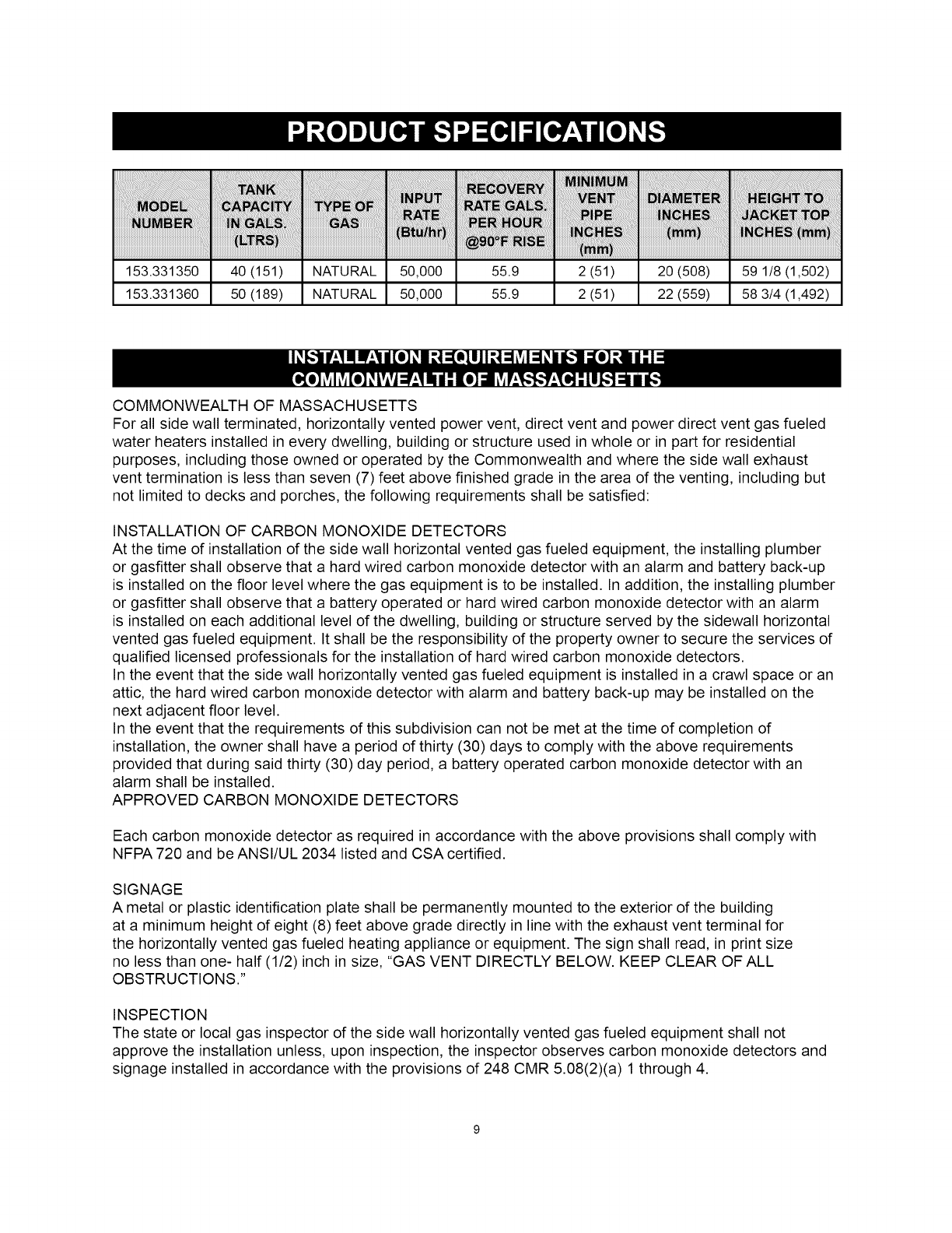
153.331350 40 (151) NATURAL 50,000 55.9 2 (51) 20 (508) 59 1/8 (1,502)
153.331360 50 (189) NATURAL 50,000 55.9 2 (51) 22 (559) 58 3/4 (1,492)
COMMONWEALTH OF MASSACHUSETTS
For all side wall terminated, horizontally vented power vent, direct vent and power direct vent gas fueled
water heaters installed in every dwelling, building or structure used in whole or in part for residential
purposes, including those owned or operated by the Commonwealth and where the side wall exhaust
vent termination is less than seven (7) feet above finished grade in the area of the venting, including but
not limited to decks and porches, the following requirements shall be satisfied:
INSTALLATION OF CARBON MONOXIDE DETECTORS
At the time of installation of the side wall horizontal vented gas fueled equipment, the installing plumber
or gasfitter shall observe that a hard wired carbon monoxide detector with an alarm and battery back-up
is installed on the floor level where the gas equipment is to be installed. In addition, the installing plumber
or gasfitter shall observe that a battery operated or hard wired carbon monoxide detector with an alarm
is installed on each additional level of the dwelling, building or structure served by the sidewall horizontal
vented gas fueled equipment. It shall be the responsibility of the property owner to secure the services of
qualified licensed professionals for the installation of hard wired carbon monoxide detectors.
In the event that the side wall horizontally vented gas fueled equipment is installed in a crawl space or an
attic, the hard wired carbon monoxide detector with alarm and battery back-up may be installed on the
next adjacent floor level.
In the event that the requirements of this subdivision can not be met at the time of completion of
installation, the owner shall have a period of thirty (30) days to comply with the above requirements
provided that during said thirty (30) day period, a battery operated carbon monoxide detector with an
alarm shall be installed.
APPROVED CARBON MONOXIDE DETECTORS
Each carbon monoxide detector as required in accordance with the above provisions shall comply with
NFPA 720 and be ANSI/UL 2034 listed and CSA certified.
SIGNAGE
A metal or plastic identification plate shall be permanently mounted to the exterior of the building
at a minimum height of eight (8) feet above grade directly in line with the exhaust vent terminal for
the horizontally vented gas fueled heating appliance or equipment. The sign shall read, in print size
no less than one- half (1/2) inch in size, "GAS VENT DIRECTLY BELOW. KEEP CLEAR OF ALL
OBSTRUCTIONS."
INSPECTION
The state or local gas inspector of the side wall horizontally vented gas fueled equipment shall not
approve the installation unless, upon inspection, the inspector observes carbon monoxide detectors and
signage installed in accordance with the provisions of 248 CMR 5.08(2)(a) 1 through 4.

EXEMPTIONS
Thefollowingequipmentisexemptfrom248CMR5.08(2)(a)1through4:
1. TheequipmentlistedinChapter10entitled"EquipmentNotRequiredToBeVented"inthemost
currenteditionof NFPA54asadoptedbytheBoard;and
2. ProductApprovedsidewallhorizontallyventedgasfueledequipmentinstalledinaroomorstructure
separatefromthedwelling,building,orstructureusedinwholeorinpartforresidentialpurposes.
MANUFACTURERREQUIREMENTS- GASEQUIPMENTVENTINGSYSTEMPROVIDED
Whenthemanufacturerof ProductApprovedsidewallhorizontallyventedgasequipmentprovidesa
ventingsystemdesignorventingsystemcomponentswiththeequipment,theinstructionsprovidedbythe
manufacturerforinstallationoftheequipmentandtheventingsystemshallinclude:
1. Detailedinstructionsfortheinstallationoftheventingsystemdesignortheventingsystem
components;and
2. Acompletepartslistfortheventingsystemdesignorventingsystem.
MANUFACTURERREQUIREMENTS- GASEQUIPMENTVENTINGSYSTEMNOTPROVIDED
Whenthemanufacturerof ProductApprovedsidewallhorizontallyventedgasfueledequipmentdoes
notprovidethepartsforventingthefluegases,butidentifies"specialventingsystems,"thefollowing
requirementsshallbesatisfiedbythemanufacturer:
1. Thereferenced"specialventingsystem"instructionsshallbeincludedwiththeapplianceor
equipmentinstallationinstructions;and
2. The"specialventingsystems"shallbeProductApprovedbytheBoard,andtheinstructionsforthat
systemshallincludea partslistanddetailedinstallationinstructions.
AcopyofallinstallationinstructionsforallProductApprovedsidewallhorizontallyventedgasfueled
equipment,allventinginstructions,allpartslistsforventinginstructions,and/orallventingdesign
instructionsshallremainwiththeapplianceorequipmentatthecompletionoftheinstallation.
10
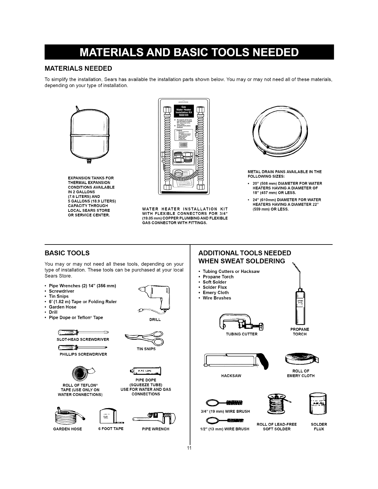
MATERIALS NEEDED
To simplify the installation, Sears has available the installation parts shown below. You may or may not need all of these materials,
depending on your type of installation.
EXPANSION TANKS FOR
THERMAL EXPANSION
CONDITIONS AVAILABLE
IN 2 GALLONS
(7.6 LITERS) AND
5 GALLONS (18.9 LITERS)
CAPACITY THROUGH
LOCAL SEARS STORE
OR SERVICE CENTER.
WATER HEATER INSTALLATION KIT
WITH FLEXIBLE CONNECTORS FOR 3/4"
(t9.05 ram) COPPER PLUMBING AND FLEXIBLE
GAS CONNECTOR WITH FITTINGS.
METAL DRAIN PANS AVAILABLE IN THE
FOLLOWING SIZES:
•20" (508 ram) DIAMETER FOR WATER
HEATERS HAVING A DIAMETER OF
18" (457 ram) OR LESS.
•24" (610ram) DIAMETER FOR WATER
HEATERS HAVING A DIAMETER 22"
(559 ram) OR LESS.
BASIC TOOLS
You may or may not need all these tools, depending on your
type of installation. These tools can be purchased at your local
Sears Store.
• Pipe Wrenches (2) 14" (356 mm)
•Screwdriver
•Tin Snips
•6' (1.82 m) Tape or Folding Ruler
•Garden Hose
•Drill
•Pipe Dope or Teflon ®Tape DRILL
SLOT-HEAD SCREWDRIVER
TIN SNIPS
PHILLIPS SCREWDRIVER
ROLL OF TEFLON ®(SQUEEZE TUBE)
TAPE (USE ONLY ON USE FOR WATER AND GAS
WATER CONNECTIONS) CONNECTIONS
GARDEN HOSE 6 FOOT TAPE PIPE WRENCH
ADDITIONAL TOOLS NEEDED
WHEN SWEAT SOLDERING
Tubing Cutters or Hacksaw
Propane Torch
Soft Solder
Solder Flux
Emery Cloth
Wire Brushes
TUBING CUTTER
HACKSAW
3/4" (q9 mm)WIRE BRUSH
1/2" (13 ram) WIRE BRUSH
ROLL OF LEAD-FREE
SOFTSOLDER
PROPANE
TORCH
ROLLOF
EMERY CLOTH
B
SOLDER
FLUX
11
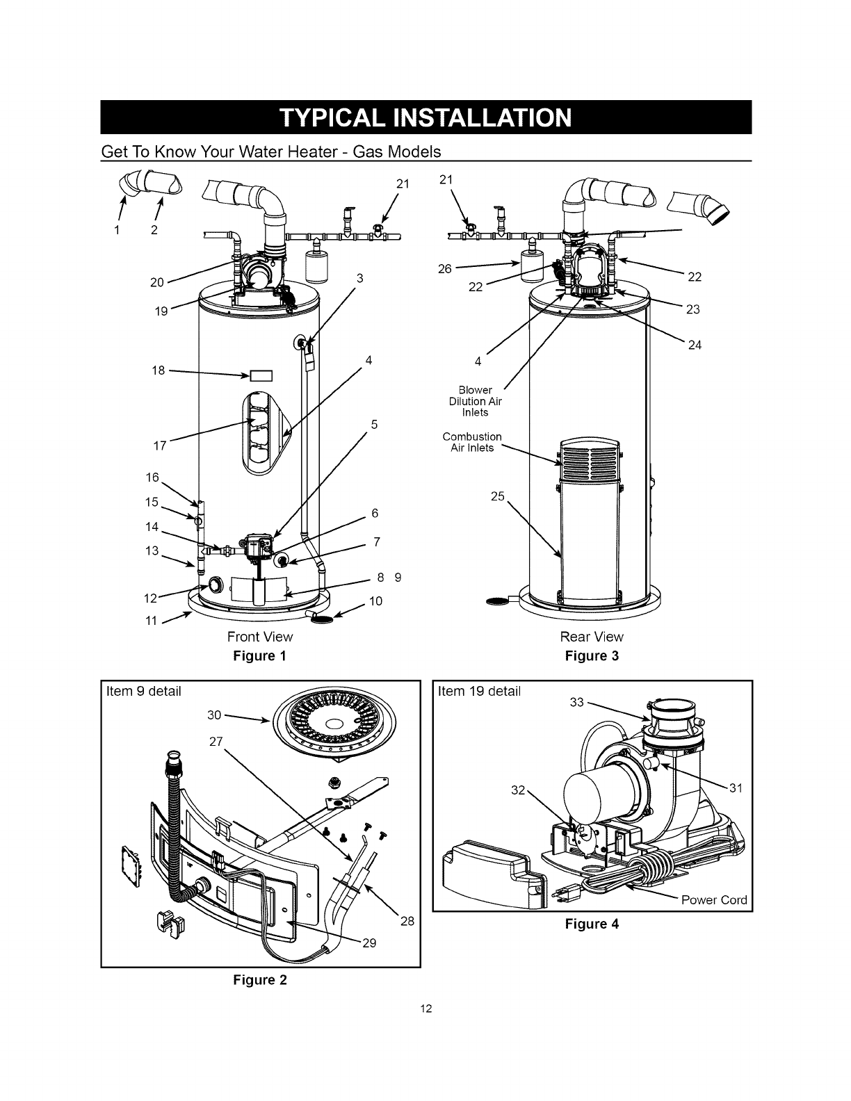
Get To Know Your Water Heater - Gas Models
21
/21
18-------
17j
16
117
Front View
Figure 1
3
/
4
/5
Item 9 detail
30 .----.........._
27
®
28
26
22 22
Blower
Dilution Air
Inlets
Combustion
Air Inlets
25 \
q
"4
Rear View
Figure 3
Item 19 detail
Figure 4
Power Cord
Figure 2
12
1 Vent Termination Elbow with Rodent Screen
2 *Vent Pipe
3 T&P Valve
4 Cold-Water Inlet Nipple/Diptube
5 Gas Control Valve/Thermostat (Honeywell)
6 **Control Harness
7 Drain Valve
8 Outer Gas Door
9 Manifold Door Assembly (behind outer door) (see Figure 2)
10 *Floor Drain
11 *Metal Drain Pan
12 Flammable Vapor Sensor (under cover)
13 *Sediment Trap/Dirt Leg
14 *Ground Joint Union (gas connection)
15 *Main Manual Gas Shut-off Valve
16 *Gas Supply
17 Baffle Assembly
18 Rating Plate
19 Blower with Power Cord
20 Rubber Coupling
21 *Inlet Water Shut-off Valve
22 *Union (water connection)
23 Hot-Water Outlet Nipple
24 Anode (under cap)
25 Air Inlet Snorkel
26 *Thermal Expansion Tank (required for all closed systems)
27 Flame Sensor Rod (see Figure 2)
28 Hot-Surface Igniter (see Figure 2)
29 Manifold Door (see Figure 2)
30 Burner
31 Blower High Limit Switch
32 Blower Air Pressure Switch
33 2" Rubber Coupling
Notes:
* Items not supplied with the water heater
** CAUTION: HARNESS HAS 120 VAC IN OPERATION.
13

This gas water heater was manufactured to voluntary safety standards to reduce the likelihood of a
flammable vapor ignition incident. The new technology used in meeting these standards makes this
product more sensitive to installation errors. Please review the following checklist and make any required
installation upgrades or changes.
Questions? Contact Sears at 1-800-4-MY-HOME (1-800-469-4663).
Installation Checklist
NOTE: Use and complete this checklist before
lighting the heater. Correct any conditions that do
not meet these instructions.
Water Heater Location
[] Centrally located with the water piping system.
Located as close to gas piping and vent pipe
system as possible.
[] Located indoors and in a vertical position.
Protected from freezing temperatures.
[] Proper clearances from combustible surfaces
maintained and not installed directly on a
carpeted floor.
[] Provisions made to protect the area from water
damage. Metal drain pan installed and piped to
an adequate drain.
[] Installation area free of corrosive elements and
flammable material.
[] Sufficient room to service the water heater.
Gas Supply and Piping
[] Gas supply is the same type as listed on the
water heater data plate.
[] Gas line equipped with shut-off valve, union
and dirt leg
[] Approved pipe joint compound used.
[] Adequate pipe size and of approved material.
[] Chloride-free soap and water solution or other
approved means used to check all connections
and fittings for possible gas leaks.
Water System Piping
[] Temperature and Pressure relief valve properly
installed with a discharge line run to an open
drain and protected from freezing.
[] All piping properly installed and free of leaks.
[] Heater completely filled with water.
[] Closed system pressure build-up precautions
installed.
Vent Pipe System
[] Vent pipe and fittings of approved material.
[] Acceptable size, length and number of elbows
on exhaust vent system.
[] Installed in accordance with prevailing
provisions of local codes, or in the absence of
such, the latest edition of "National Fuel Gas
Code" ANSI Z223.1 (NFPA 54).
[] Horizontal piping slopes at an upward pitch of
1/8 in. (3mm) rise per 4 ft. (1.2m) away from
the water heater.
[] Not obstructed in any way.
Vent Termination
Horizontal
[] 12 in. (300mm) min. above grade/snow level.
[] Away from corners, other vents, windows etc.
Vertical
[] Exhaust vent termination 18 in. (457mm) min.
above roof/snow level.
Electrical Connections
[] Unit connected to a dedicated 120V electrical
supply.
[] Proper polarity.
[] Water heater properly grounded.
[] Installed in accordance with prevailing
provisions of local codes, or in the absence of
such, the latest edition of "National Electrical
Code" (NFPA 70)".
After all actions on checklist are checked/
completed, read the Lighting Instructions and
proceed with lighting the heater.
14
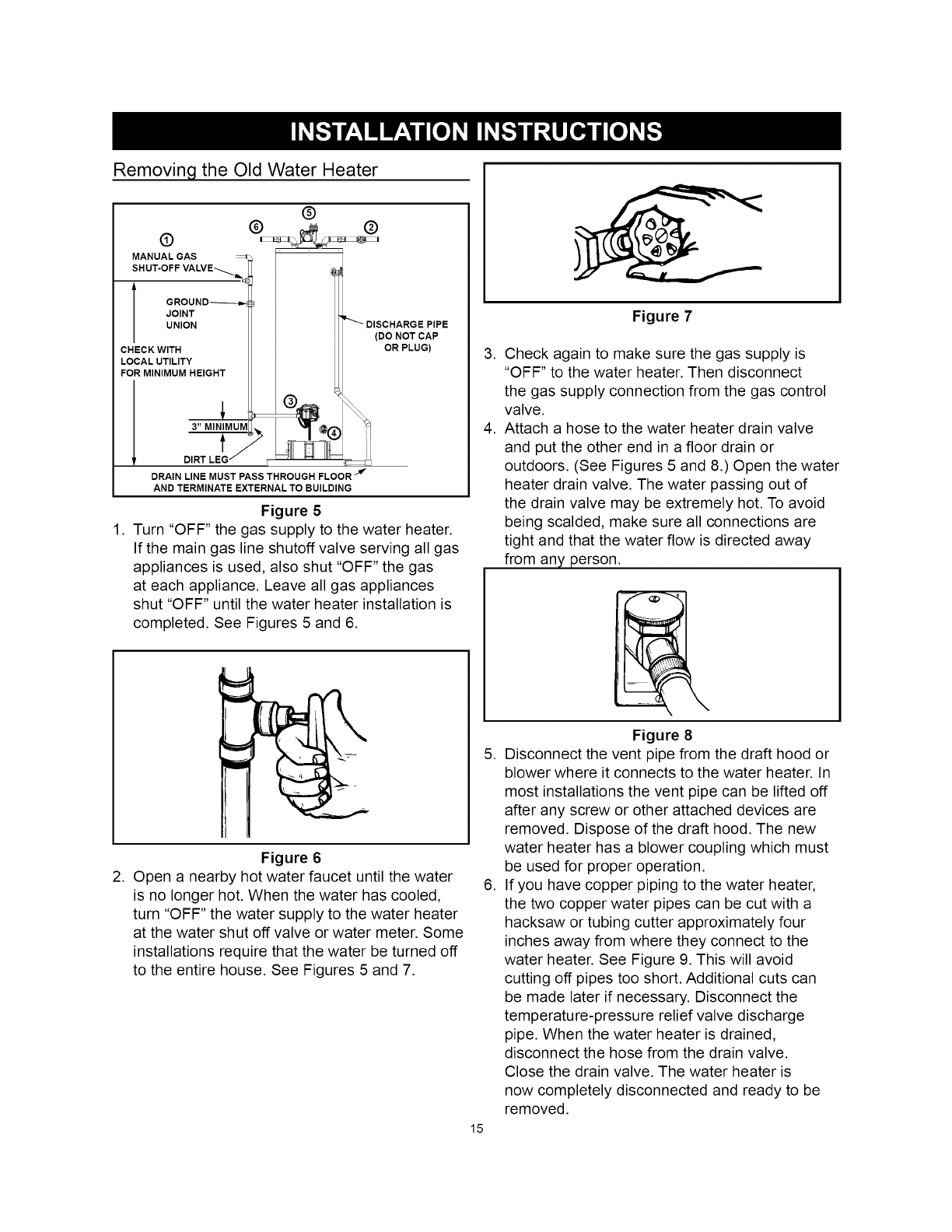
Removing the Old Water Heater
®
@ ®
®
MANUAL GAS
SHUT-OFF
JOINT
UNION
CHECK WITH
LOCAL UTILITY
FOR MINIMUM HEIGHT
J3" MINIMUM
DIRT LEG ,,
DRAIN LINE MUST PASS THROUGH FLOOR _
AND TERMINATE EXTERNAL TO BUILDING
(DO NOT CAP
OR PLUG)
Figure 5
1. Turn "OFF" the gas supply to the water heater.
If the main gas line shutoff valve serving all gas
appliances is used, also shut "OFF" the gas
at each appliance. Leave all gas appliances
shut "OFF" until the water heater installation is
completed. See Figures 5 and 6.
,
,
Figure 7
Check again to make sure the gas supply is
"OFF" to the water heater. Then disconnect
the gas supply connection from the gas control
valve.
Attach a hose to the water heater drain valve
and put the other end in a floor drain or
outdoors. (See Figures 5 and 8.) Open the water
heater drain valve. The water passing out of
the drain valve may be extremely hot. To avoid
being scalded, make sure all connections are
tight and that the water flow is directed away
from any person.
Figure 6
2. Open a nearby hot water faucet until the water
is no longer hot. When the water has cooled,
turn "OFF" the water supply to the water heater
at the water shut off valve or water meter. Some
installations require that the water be turned off
to the entire house. See Figures 5 and 7.
,
15
,
Figure 8
Disconnect the vent pipe from the draft hood or
blower where it connects to the water heater. In
most installations the vent pipe can be lifted off
after any screw or other attached devices are
removed. Dispose of the draft hood. The new
water heater has a blower coupling which must
be used for proper operation.
If you have copper piping to the water heater,
the two copper water pipes can be cut with a
hacksaw or tubing cutter approximately four
inches away from where they connect to the
water heater. See Figure 9. This will avoid
cutting off pipes too short. Additional cuts can
be made later if necessary. Disconnect the
temperature-pressure relief valve discharge
pipe. When the water heater is drained,
disconnect the hose from the drain valve.
Close the drain valve. The water heater is
now completely disconnected and ready to be
removed.
Figure9
Ifyouhavegalvanizedpipestothewaterheater,
loosenthetwogalvanizedpipeswithapipe
wrenchattheunionineachline.Alsodisconnect
thepipingremainingtothewaterheater.See
Figure10.Thesepiecesshouldbesavedsince
theymaybeneededwhenreconnectingthenew
waterheater.Mineralbuilduporsedimentmay
haveaccumulatedintheoldwaterheater.This
causesthewaterheatertobemuchheavier
thannormalandthisresidue,if spilledout,could
causestaining.
Facts To Consider About The Location
Carefully choose an indoor location for the
new water heater because the placement is a
very important consideration for the safety of
the occupants in the building and for the most
economical use of the appliance. This water heater
is not for use in manufactured (mobile) homes or
outdoor installation.
Whether replacing an old water heater or putting
the water heater in a new location, the following
critical points must be observed:
1. Select a location indoors as close as practical
to the vent termination or location to which
the water heater vent piping is going to be
connected, and as centralized with the water
piping system as possible.
2. Selected location must provide adequate
clearances for servicing and proper operation
of the water heater.
3. Ensure the area has a continuous supply of air
for combustion, dilution and ventilation.
4. Avoid locations that could cause the water
heater to freeze from outside air.
5. Selected location must provide access to a
properly grounded electrical branch circuit. A
dedicated circuit is preferred. Do not use a GFI
outlet.
6. Avoid locations that expose the water heater to
direct sunlight.
7. Keep combustibles such as boxes, magazines,
clothes, etc., away from the water heater area.
8. The water heater must be located and/or
protected so it is not subject to physical
damage by a moving vehicle.
IMPORTANT: Do not use an extension cord to
connect the water heater to an electrical outlet.
IMPORTANT: This heater has special venting
requirements when installed in areas where the
ambient temperatures exceed 110°F (43°C) (see
"Hi( h Ambient Tem )erature Installations"
Property Damage Hazard
• All water heaters eventually leak.
• Do not install without adequate drainage,
Installation of the water heater must be
accomplished in such a manner that if the tank
or any connections should leak, the flow of water
will not cause damage to the structure. For this
reason it is not advisable to install the water heater
in an attic or upper floor. In all cases, a metal drain
16

pan should be installed under the water heater.
Such a metal drain pan must have a clearance of
at least 1" (25mm) greater than any point on the
water heater's outer jacket and must be piped to
an adequate drain. The pan must have a maximum
depth of 1.75" (45mm).
Water heater life depends upon water quality,
water pressure and the environment in which
the water heater is installed. Water heaters are
sometimes installed in locations where leakage
may result in property damage, even with the use
of a metal drain pan piped to a drain. However,
unanticipated damage can be reduced or prevented
by a leak detector or water shut-off device used in
conjunction with a piped metal drain pan. These
devices are available from some plumbing supply
wholesalers and retailers, and detect and react to
leakage in various ways:
• Sensors mounted in the metal drain pan that
trigger an alarm or turn off the incoming water to
the water heater when leakage is detected.
• Sensors mounted in the metal drain pan that
turn off the water supply to the entire building
when water is detected in the metal drain pan.
• Water supply shut-off devices that activate
based on the water pressure differential between
the cold-water and hot-water pipes connected to
the water heater.
• Devices that will turn off the gas supply to a gas
water heater while at the same time shutting off
its water supply.
producing appliance. Examples of such locations
are garages, storage and utility areas.
Fire or Explosion Hazard
• Do not store or use gasoline or other flammable vapors and
liquids in the vicinity of this or any other appliance.
• Avoid all ignition sources if you smell gas.
• Do not expose water heater control to excessive gas
pressure.
• Use only gas shown on rating plate.
• Maintain required clearances to combustibles.
• Keep ignition sources away from faucets after extended
period of non-use,
l_ Read instruction manual before
installing, using or servicing
water heater.
FIRE AND EXPLOSION HAZARD
Can result in serious injury or death
,_Do not store or use gasoline or other flammable vapors and
liquids in the vicinity of this or any other appliance. Storage or
use of gasoline or other flammable vapors or liquids in the
vicinity of this or any other appliance can result in serious injury
or death.
Storage Of Flammable Liquids
Flammable liquids (such as gasoline, solvents,
propane (LP or butane, etc.) and other substances
(such as adhesives, paints, etc.) emit flammable
vapors which can be ignited by a gas water
heater's hot surface igniter (HSI) or main burner.
The resulting flashback and fire can cause death or
serious burns to anyone in the area.
This water heater is equipped with a FV
(Flammable Vapor) sensor for detecting the
presence of flammable vapors. When the sensor
detects those vapors, the unit will shut down and
not operate. Should this happen, please refer
to the "Troubleshooting Guidelines" section of
this manual. Even though this water heater is a
flammable vapors ignition resistant (FVlR) water
heater and is designed to reduce the chances of
flammable vapors being ignited, gasoline and other
flammable substances should never be stored
or used in the same vicinity or area containing
a gas water heater or other open flame or spark
Fire Hazard
For continued protection against
risk of fire:
• Do not install water heater on
carpeted floor.
• Do not operate water heater if
flood damaged.
Clearances To Combustibles
Minimum clearances between water heater and
combustibles are 0" at the sides and rear, 5.5"
(140mm) from the front and 12" (300mm) from top
(standard clearance.) If clearances stated on the
heater differ from standard clearances, install water
heater according to clearances stated on the heater
(see Figure 11).
NOTE: Do not block air intakes at the rear of the
water heater.
17
Floors With Carpeting
This water heater must not be installed directly on
carpeting. Carpeting must be protected by a metal
or wood panel beneath the appliance extending
beyond the full width and depth of the appliance
by at least 3" (76mm) in every direction, or if the
appliance is installed in an alcove or closet, the
entire floor must be covered by the panel. Failure to
heed this warning may result in a fire hazard.
Clearance For Servicing
Adequate clearance of 24" (610mm) for servicing
this appliance should be considered before
installation, such as changing the anodes, etc.
A minimum clearance of 5.5" (140mm) must be
allowed for access to replaceable parts such as
thermostats, drain valve and relief valve.
When installing the heater, consideration must
be given to proper location. Location selected
should be as close to the wall as practicable and
as centralized with the water piping system as
possible.
TOP VIEW
OF CLOSET
WITHOUT DOOR
0" MIN. _
0" MIN.' _'-
5.5" (14cm)
MIN. TO
INSIDE OF
DOOR"
TOP VIEW OF
CLOSET WITH
DOOR
*DO NOT BLOCK THE AIR INTAKES AT THE BACK OF THE WATER HEATER.
Figure 11
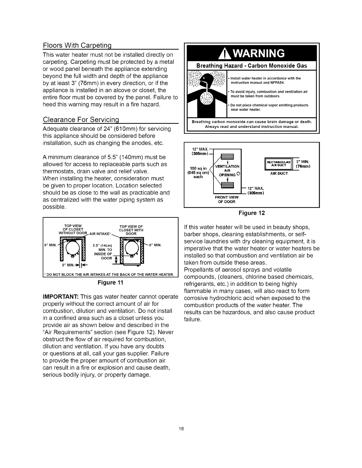
IMPORTANT: This gas water heater cannot operate
properly without the correct amount of air for
combustion, dilution and ventilation. Do not install
in a confined area such as a closet unless you
provide air as shown below and described in the
"Air Requirements" section (see Figure 12). Never
obstruct the flow of air required for combustion,
dilution and ventilation. If you have any doubts
or questions at all, call your gas supplier. Failure
to provide the proper amount of combustion air
can result in a fire or explosion and cause death,
serious bodily injury, or property damage.
Breathing Hazard -Carbon Monoxide Gas
• Install water heater in accordance with the
instruction manual and NFPA54.
•To avoid injury, combustion and ventilation air
must be taken from outdoors.
•Do not place chemical vapor emitting products
near water heater.
Breathing carbon monoxide can cause brain damage or death.
Always read and understand instruction manual.
12" MAX. /
(305mm)
.... AVENTILATION
-IUUSq In _I AIR
(645 sq. cm) _1 OPENING O
eacn
FRONT VIEW
OF DOOR
IRECTAIIGULAR (3" MIN.
AiRDUCT (76mm)
AIR DUCT
-- 12" MAX.
(305mm)
Figure 12
If this water heater will be used in beauty shops,
barber shops, cleaning establishments, or self-
service laundries with dry cleaning equipment, it is
imperative that the water heater or water heaters be
installed so that combustion and ventilation air be
taken from outside these areas.
Propellants of aerosol sprays and volatile
compounds, (cleaners, chlorine based chemicals,
refrigerants, etc.)in addition to being highly
flammable in many cases, will also react to form
corrosive hydrochloric acid when exposed to the
combustion products of the water heater. The
results can be hazardous, and also cause product
failure.
18
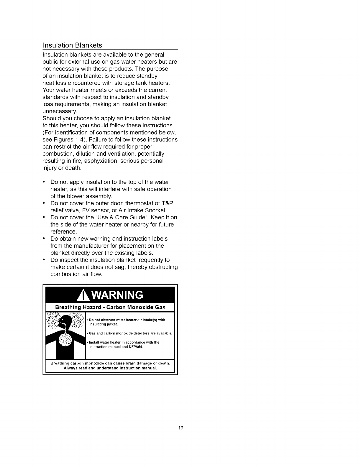
Insulation Blankets
Insulation blankets are available to the general
public for external use on gas water heaters but are
not necessary with these products The purpose
of an insulation blanket is to reduce standby
heat loss encountered with storage tank heaters
Your water heater meets or exceeds the current
standards with respect to insulation and standby
loss requirements making an insulation blanket
unnecessary
Should you choose to apply an insulation blanket
to this heater you should follow these instructions
(For identification of components mentioned below
see Figures 14) Failure to follow these instructions
can restrict the air flow required for proper
combustion, dilution and ventilation potentially
resulting in fire asphyxiation serious personal
injury or death
• Do not apply insulation to the top of the water
heater as this will interfere with safe operation
of the blower assembly
• Do not cover the outer door thermostat or T&P
relief valve FV sensor or Air Intake Snorkel
• Do not cover the Use & Care Guide Keep it on
the side of the water heater or nearby for future
reference
• Do obtain new warning and instruction labels
from the manufacturer for placement on the
blanket directly over the existing labels
• Do inspect the insulation blanket frequently to
make certain it does not sag thereby obstructing
combustion air flow
Breathing Hazard -Carbon Monoxide Gas
• Do not obstruct water heater air intake(s) with
insulating jacket.
•Gas and carbcn monoxide detectors are available.
•install water heater in accordance with the
instruction manual and NFPA54.
Breathing carbon monoxide can cause brain damage or death.
Always read and understand instruction manual.
19
Gas Piping
Fire and Explosion Hazard
• Do not use water heater with
any gas other than the gas
shown on the rating plate.
• Excessive pressure to gas
control valve can cause serious
injury or death.
• Turn off gas lines during
installation.
• Contact qualified installer or
service agency.
A gas line of sufficient size must be run to the water
heater. Consult the current edition of National Fuel
Gas Code (ANSI Z223.1/NFPA 54) and your gas
supplier concerning pipe size.
There must be:
• A readily accessible manual shut-off valve in the
gas supply line serving the water heater, and
• A sediment trap (dirt leg) ahead of gas control
valve/thermostat to help prevent dirt and foreign
materials from entering the gas control valve/
thermostat.
• Aflexible gas connector or a ground joint union
between the shut-off valve and gas control
valve/thermostat to permit servicing of the unit.
Explosion Hazard
Havea qualifiedtechnicianmake surethat the L.P.
gas operating pressuredoes notexceed 13" water
column (3.237 kilopascals).
Failureto do so can result in death, explosion,or
fire.
Make sure the gas supplied is the same type listed
on the model rating plate. The inlet gas pressure
must not exceed 14 inch w.c. (3.5kPa) for natural
gas and propane gas. The minimum inlet gas
pressure shown on the rating plate is that which will
permit firing at rated input.
All gas piping must comply with local codes and
ordinances or with the National Fuel Gas Code
(ANSI Z223.1/NFPA-54). Copper or brass tubing
and fittings (except tin lined copper tubing) should
not be used.
If the gas control valve/thermostat is subjected to
pressures exceeding 1/2 psi (3.5kPa), the damage
to the gas control valve/thermostat could result in a
fire or explosion from leaking gas. If the main gas
line shut-off serving all gas appliances is used, also
turn "OFF" the gas at each appliance. Leave all
gas appliances shut "OFF" until the water heater
installation is complete.
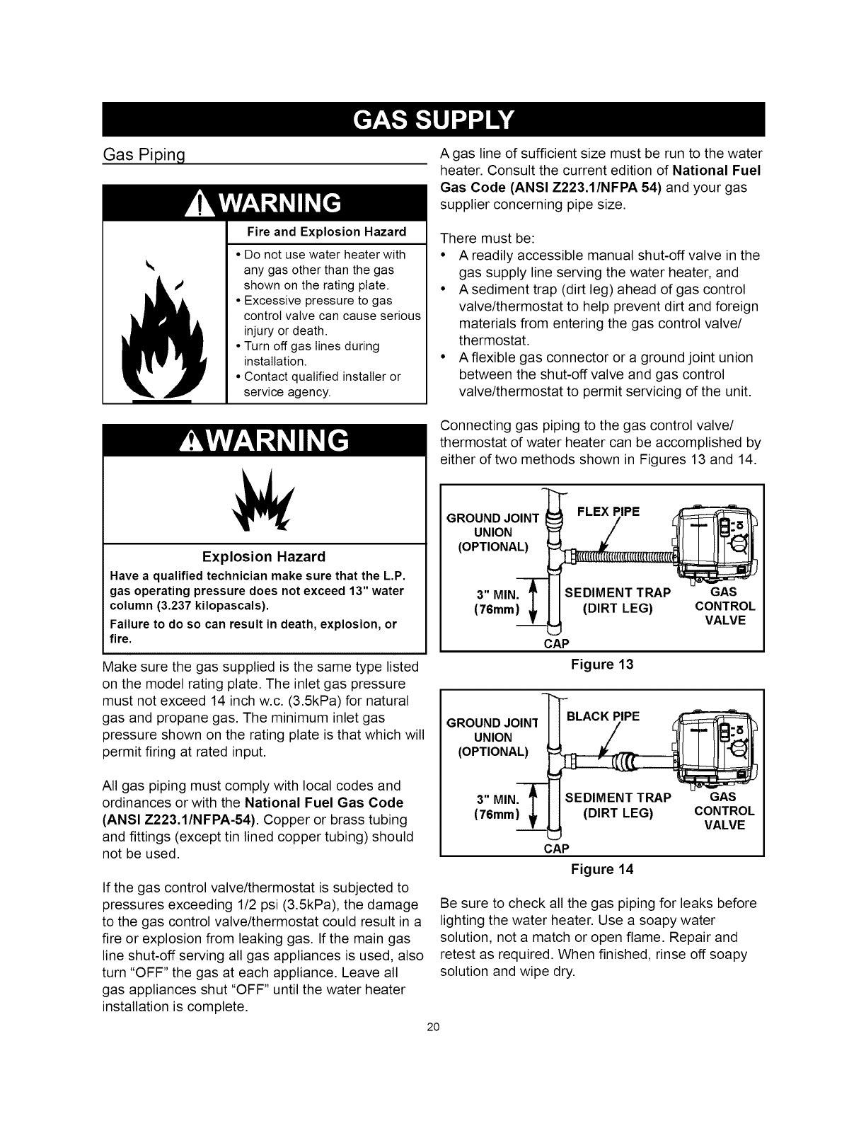
Connecting gas piping to the gas control valve/
thermostat of water heater can be accomplished by
either of two methods shown in Figures 13 and 14.
GROUND JOINT FLEX PIPE
UNION "_ I./
(OPTIONA_
3" MIN. _I I SEDIMENT TRAP GAS
(76mm} _I I (DIRT LEG) CONTROL
T _ VALVE
CAP
Figure 13
GROUND JOIN1
UNION
(OPTIONAL)
CAP
Figure 14
Be sure to check all the gas piping for leaks before
lighting the water heater. Use a soapy water
solution, not a match or open flame. Repair and
retest as required. When finished, rinse off soapy
solution and wipe dry.
2O
Fire and Explosion Hazard
•Use joint compound or tape
compatible with natural gas
and propane.
• Leak test before operating
heater.
• Disconnect gas piping and
shut-off valve before pressure
testing system.
Use pipe joint compound or Teflon tape marked as
being resistant to the action of gases.
The appliance and its gas connection must be leak
tested before placing the appliance in operation.
The appliance and its individual shut-off valve
should be disconnected from the gas supply piping
system during any pressure testing of that system
at test pressures in excess of 1/2 psi (3.5kPa).
It should be isolated from the gas supply piping
system by closing its individual manual shut-off
valve during any pressure testing of the gas supply
piping system at test pressures equal to or less
than 1/2 psi (3.5kPa).
Sediment Traps/Dirt Leg
Fire and Explosion Hazard
• Contaminants in gas lines can
cause fire or explosion.
• Clean all gas piping before
installation.
• Install sediment trap (dirt leg)
in accordance with NFPA54.
A sediment trap should be installed as close to the
inlet of the water heater as practical at the time of
water heater installation. The sediment trap should
be either a tee fitting with a capped nipple in the
bottom outlet or other device recognized as an
effective sediment trap. If a tee fitting is used, it
should be installed in conformance with one of the
methods of installation shown in Figures 13 and 14.
Contaminants in the gas lines may cause improper
operation of the gas control valve/thermostat that
may result in fire or explosion. Before attaching
the gas line be sure that all gas pipe is clean on
the inside. To trap any dirt or foreign material in the
gas supply line, a sediment trap (sometimes called
a dirt leg) must be incorporated in the piping. The
sediment trap must be readily accessible. Install in
accordance with the "Gas Piping" section. Refer to
the current edition of the National Fuel Gas Code
(ANSI Z223.1/NFPA 5 4).
High Altitude Installation
Breathing Hazard -Carbon Monoxide Gas
• For operation above 10,100 ft.
(3,048 metres) a high altitude
orifice must be installed.
• Contact a qualified installer or
service agency.
Breathing carbon monoxide can cause brain damage or death.
Always read and understand instruction manual.
This heater is approved for operation up to 10,100
feet (3,079 m) without alteration.
Failure to replace standard orifice with a high
altitude orifice when installed above 10,100 feet
(3,079 m) could result in improper and inefficient
operation of the appliance, producing carbon
monoxide gas in excess of safe limits, which could
result in serious injury or death. Contact your gas
supplier for any specific changes which may be
required in your area.
21

Air Requirements
For safe operation an adequate supply of fresh,
uncontaminated air for combustion, dilution and
ventilation must be provided.
NOTE: Contaminated or dusty air may cause build-
up on the blower wheel resulting in nuisance shut
downs.
An insufficient supply of air can cause recirculation
of combustion products resulting in contamination
that may be hazardous to life. Such a condition
often will result in a yellow, luminous burner flame,
causing sooting of the combustion chamber,
burners and flue tubes and creates a risk of
asphyxiation.
Do not install the water heater in a confined space
unless an adequate supply of air for combustion,
dilution and ventilation is brought into that space
using the methods described in the "Confined
Space" section that follows.
Never obstruct the flow of combustion, dilution and
ventilation air. If you have any doubts or questions
at all, call your gas supplier. Failure to provide
the proper amounts of air can result in a fire or
explosion and cause property damage, serious
bodily injury or death. The combustion and dilution
air inlets are shown in Figure 2.
Unusually Tight Construction
In unconfined spaces in buildings, infiltration
may be adequate to provide air for combustion,
ventilation and dilution of flue gases. However,
in buildings of unusually tight construction (e.g.,
weather stripping, heavily insulated, caulked, vapor
barrier, etc.) additional air must be provided using
the methods described in the "Confined Space"
section that follows.
Confined Space
A Confined Space is one whose volume is less than
50 cubic feet per 1,000 Btu/hr (4.8m3/kW) of the
total input rating of all appliances installed in the
space.
Openings must be installed to provide fresh air for
combustion, ventilation and dilution in confined
spaces. The required size for the openings is
dependent on the method used to provide fresh
air to the confined space and the total Btu/hr input
rating of all appliances installed in the space.
Direct Vent Appliances
Other appliances installed in a Direct Vent
configuration that derive all air for combustion from
the outdoor atmosphere through sealed intake air
piping are not factored in the total appliance input
Btu/hr calculations used to determine the size of
openings providing fresh air into confined spaces.
IMPORTANT: Power Vented water heaters require
air for combustion and dilution air for the blower.
Adequate ventilation air is required to minimize heat
buildup around the heater.
Unconfined Space
An Unconfined Space is one whose volume is not
less than 50 cubic feet per 1,000 Btu/hr (4.8m3/kW)
of the total input rating of all appliances installed in
the space. Rooms communicating directly with the
space in which the appliances are installed, through
openings not furnished with doors, are considered
a part of the unconfined space.
Exhaust Fans
Where exhaust fans are installed, additional air
should be provided to replace the exhausted air.
When an exhaust fan is installed in the same space
with a water heater, sufficient openings to provide
fresh air must be provided that accommodate the
requirements for all appliances in the room and the
exhaust fan. Undersized openings will cause air to
be drawn into the room through the water heater's
vent system causing poor combustion. Sooting,
serious damage to the water heater and the risk of
fire or explosion may result. It can also create a risk
of asphyxiation.
Makeup air requirements for the operation of
exhaust fans, kitchen ventilation systems, clothes
dryers and fireplaces should also be considered
in determining the adequacy of a space to provide
combustion, ventilation and dilution air.
Fresh Air Openings For Confined Spaces
The following instructions should be used to
calculate the size, number and placement of
openings providing fresh air for combustion,
ventilation and dilution in confined spaces. The
22
illustrations shown in this section of the manual
are a reference for the openings that provide fresh
air into confined spaces only. Do not refer to these
illustrations for the purpose of vent installation. See
"Venting" section for complete venting installation
instructions.
Chemical vapor corrosion of the flue, blower
assembly and vent system may occur if the air
supply contains certain chemical vapors. Spray can
propellants, cleaning solvents, refrigerator and air
conditioner refrigerants, swimming pool chemicals,
calcium and sodium chloride (water softener salt),
waxes, bleach and process chemicals are typical
compounds which are potentially corrosive.
All Air From Inside Buildings
The confined space shall be provided with two
permanent openings communicating directly with
an additional room(s) of sufficient volume so that
the combined volume of all spaces meets the
criteria for an unconfined space. The total input
of all gas utilization equipment installed in the
combined space shall be considered in making
this determination. Each opening shall have a
minimum free area of one square inch per 1,000
Btu/hr (22cm2/kW) of the total input rating of all
gas utilization equipment in the confined space,
but not less than 100 square inches (645cm2). One
opening shall commence within 12" (300mm) of the
top and one commencing within 12" (300mm) of the
bottom of the enclosures (see Figure 15).
Figure 15
All Air From Outdoors
The confined space shall be provided with two
permanent openings, one commencing within 12"
(300mm) of the top and one commencing within
12" (300mm)from the bottom of the enclosure. The
openings shall communicate directly, or by ducts,
with the outdoors or spaces (crawl or attic) that
freely communicate with the outdoors.
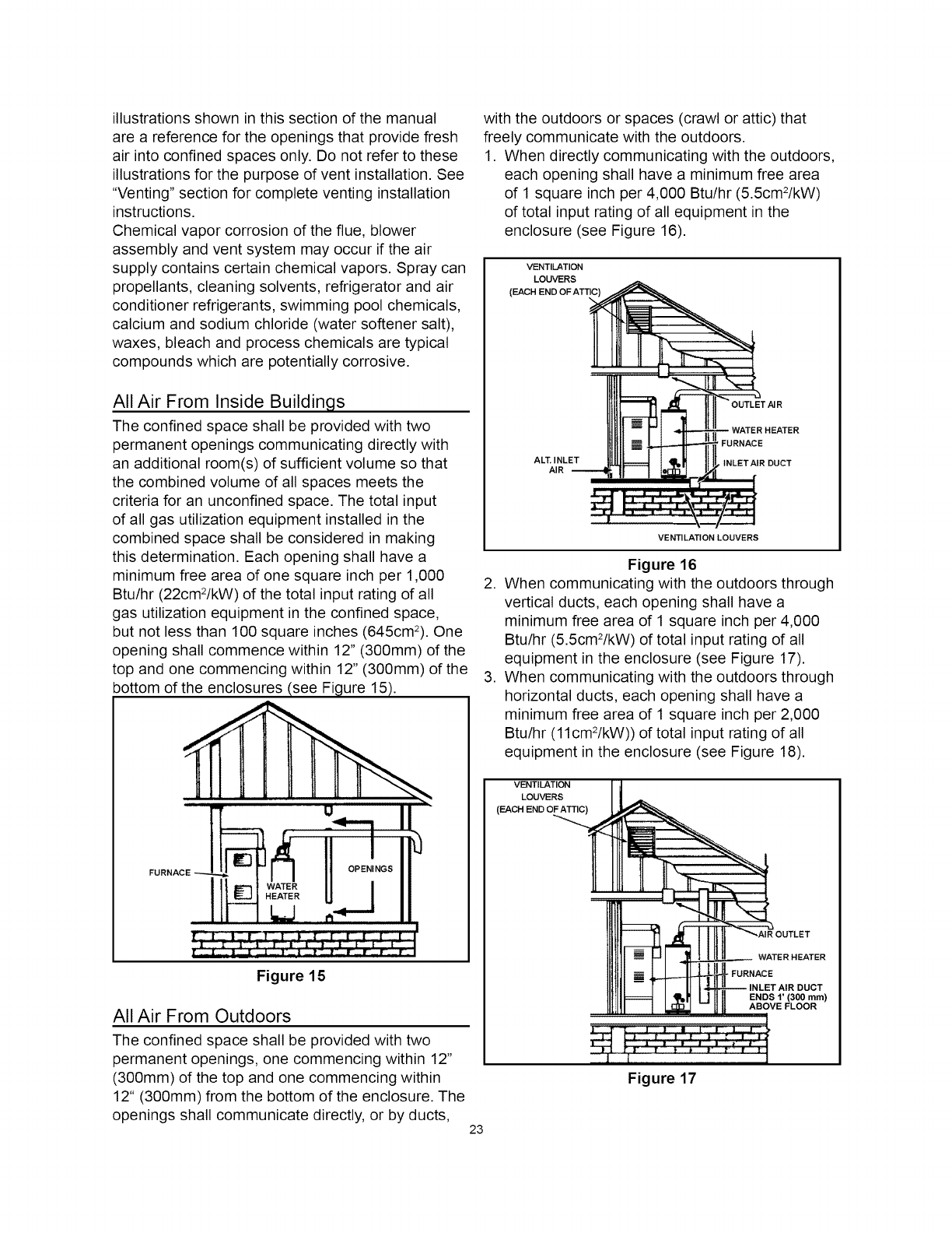
1. When directly communicating with the outdoors,
each opening shall have a minimum free area
of 1 square inch per 4,000 Btu/hr (5.5cm2/kW)
of total input rating of all equipment in the
enclosure (see Figure 16).
VENTILATION
LOUVERS
(EACH END OF ATTIC)
AL_INLET
AIR
'FURNACE
INLETAIR DUCT
VENTILATION LOUVERS
Figure 16
2. When communicating with the outdoors through
vertical ducts, each opening shall have a
minimum free area of 1 square inch per 4,000
Btu/hr (5.5cm2/kW) of total input rating of all
equipment in the enclosure (see Figure 17).
3. When communicating with the outdoors through
horizontal ducts, each opening shall have a
minimum free area of 1 square inch per 2,000
Btu/hr (11cm2/kW)) of total input rating of all
equipment in the enclosure (see Figure 18).
VENTILATION
LOUVERS
(EACH
WATER HEATER
-FURNACE
ENDS 1' (300 mm)
ABOVE FLOOR
Figure 17
23
4. When ducts are used, they shall be of the same
cross-sectional area as the free area of the
openings to which they connect. The minimum
short side dimension of rectangular air ducts
shall not be less than 3" (76mm) (see Figure
18).
tll-: FuRNAcEl
Hurm_, ,, _#O2u%
Figure 18
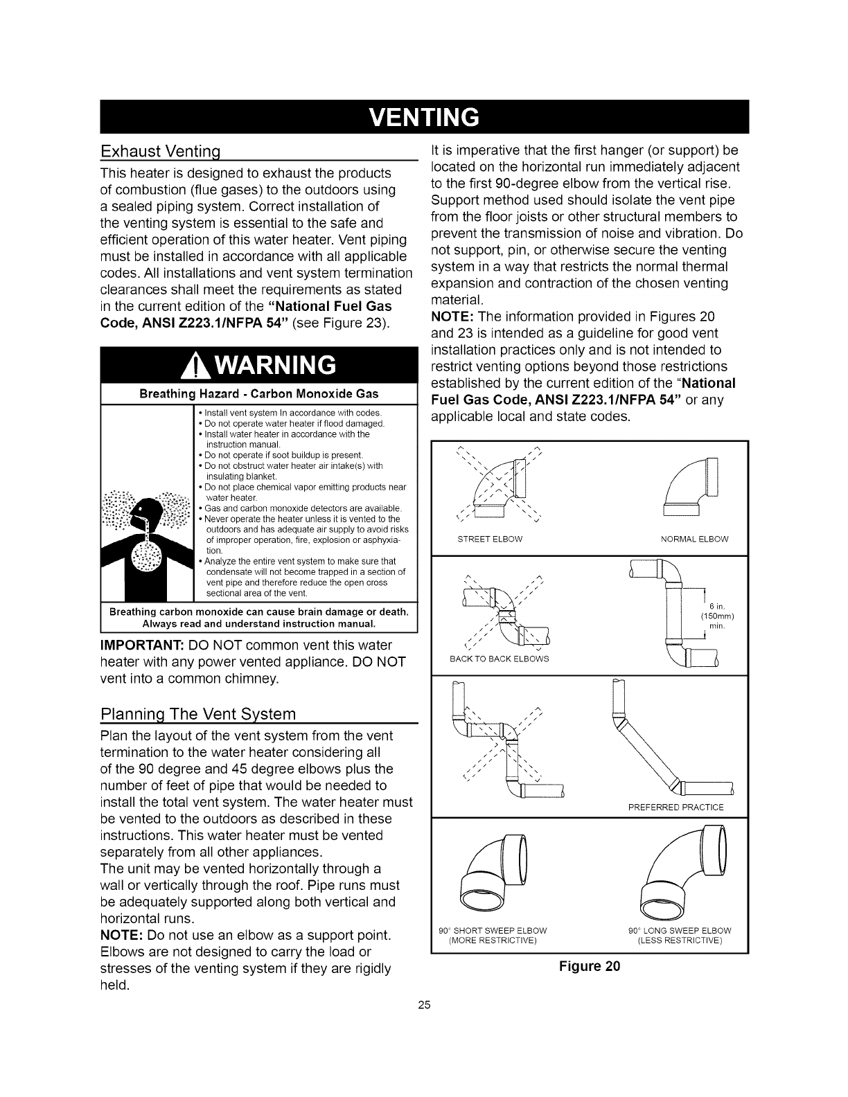
5. Alternatively a single permanent opening
may be used when communicating directly
with the outdoors, or with spaces that freely
communicate with the outdoors. The opening
shall have a minimum free area of 1 square inch
per 3,000 Btu/hr (7.3cm2/kW) of total input rating
of all equipment in enclosure (see Figure 19).
m
CHIMNEY
OR
O EN,N
oo.,,ON
' ' " ' ' ' I
Figure 19
6. Louvers and Grilles: In calculating free area,
consideration shall be given to the blocking
effect of louvers, grilles or screens protecting
openings. Screens used shall not be smaller
than 1/4" (6.4mm) mesh. If the free area through
a design of louver or grille is known, it should be
used in calculating the size opening required to
provide the free area specified. If the design and
free area is not known, it may be assumed that
wood louvers will be 20-25 percent free area
and metal louvers and grilles will have 60-75
percent free area. Louvers and grilles shall be
fixed in the open position or interlocked with the
equipment so that they are opened automatically
during equipment operation.
7. Special Conditions Created by Mechanical
Exhausting or Fireplaces: Operation of
exhaust fans, ventilation systems, clothes dryers
or fireplaces may create conditions requiring
special attention to avoid unsatisfactory
operation of installed gas utilization equipment.
Chemical Vapor Corrosion
CORROSION OF THE FLUEWAYS AND VENT
SYSTEM MAY OCCUR IFAIR FOR COMBUSTION
CONTAINS CERTAIN CHEMICAL VAPORS. SUCH
CORROSION MAY RESULT IN FAILURE AND
RISK OF ASPHYXIATION.
Spray can propellants, cleaning solvents,
refrigerator and air conditioning refrigerants,
swimming pool chemicals, calcium and sodium
chloride (water softener salt), waxes, and process
chemicals are typical compounds which are
potentially corrosive. Do not store products of this
sort near the heater. Also air which is brought in
contact with the heater should not contain any of
the chemicals. If necessary, uncontaminated air
should be obtained from remote or outside sources.
24
Exhaust Venting
This heater is designed to exhaust the products
of combustion (flue gases) to the outdoors using
a sealed piping system. Correct installation of
the venting system is essential to the safe and
efficient operation of this water heater. Vent piping
must be installed in accordance with all applicable
codes. All installations and vent system termination
clearances shall meet the requirements as stated
in the current edition of the "National Fuel Gas
Code, ANSI Z223.1/NFPA 54" (see Figure 23).
Breathing Hazard - Carbon Monoxide Gas
• Instattvent system In accordance with codes.
• Do not operate water heater if flood damaged.
• Instattwater heater in accordance with the
instruction manual.
• Do not operate if soot buildup is present.
• Do not obstruct water heater air intake(s) with
insulating blanket.
• Do not place chemical vapor emitting products near
water heater,
• Gas and carbon monoxide detectors are available,
• Never operate the heater unless it is vented to the
outdoors and has adequate air supply to avoid risks
of improper operation, fire, explosion or asphyxia-
tion.
• Analyze the entire vent system to make sure that
condensate will not become trapped in a section of
vent pipe and therefore reduce the open cross
sectional area of the vent,
Breathing carbon monoxide can cause brain damage or death.
Always read and understand instruction manual.
IMPORTANT: DO NOT common vent this water
heater with any power vented appliance. DO NOT
vent into a common chimney.
Planning The Vent System
Plan the layout of the vent system from the vent
termination to the water heater considering all
of the 90 degree and 45 degree elbows plus the
number of feet of pipe that would be needed to
install the total vent system. The water heater must
be vented to the outdoors as described in these
instructions. This water heater must be vented
separately from all other appliances.
The unit may be vented horizontally through a
wall or vertically through the roof. Pipe runs must
be adequately supported along both vertical and
horizontal runs.
NOTE: Do not use an elbow as a support point.
Elbows are not designed to carry the load or
stresses of the venting system if they are rigidly
held.
It is imperative that the first hanger (or support) be
located on the horizontal run immediately adjacent
to the first 90-degree elbow from the vertical rise.
Support method used should isolate the vent pipe
from the floor joists or other structural members to
prevent the transmission of noise and vibration. Do
not support, pin, or otherwise secure the venting
system in a way that restricts the normal thermal
expansion and contraction of the chosen venting
material.
NOTE: The information provided in Figures 20
and 23 is intended as a guideline for good vent
installation practices only and is not intended to
restrict venting options beyond those restrictions
established by the current edition of the "National
Fuel Gas Code, ANSI Z223.1/NFPA 54" or any
applicable local and state codes.
/ /
STREET ELBOW NORMAL ELBOW
6 in.m)
BACK TO BACK ELBOWS
/ /> \
90 ° SHORT SWEEP ELBOW
(MORE RESTRICTIVE)
PREFERRED PRACTICE
90 ° LONG SWEEP ELBOW
(LESS RESTRICTIVE)
Figure 20
25
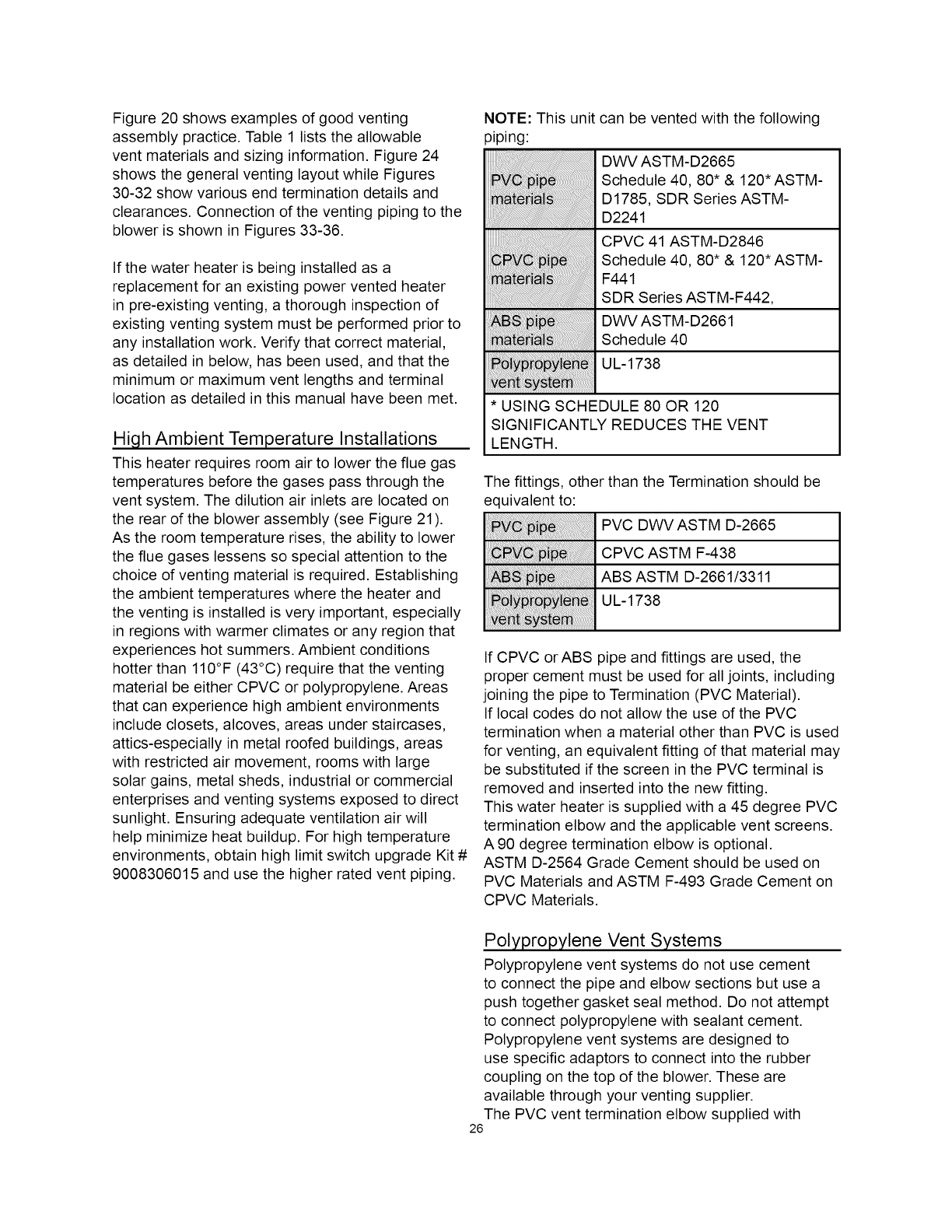
Figure 20 shows examples of good venting
assembly practice. Table 1 lists the allowable
vent materials and sizing information. Figure 24
shows the general venting layout while Figures
30-32 show various end termination details and
clearances. Connection of the venting piping to the
blower is shown in Figures 33-36.
If the water heater is being installed as a
replacement for an existing power vented heater
in pre-existing venting, a thorough inspection of
existing venting system must be performed prior to
any installation work. Verify that correct material,
as detailed in below, has been used, and that the
minimum or maximum vent lengths and terminal
location as detailed in this manual have been met.
High Ambient Temperature Installations
This heater requires room air to lower the flue gas
temperatures before the gases pass through the
vent system. The dilution air inlets are located on
the rear of the blower assembly (see Figure 21).
As the room temperature rises, the ability to lower
the flue gases lessens so special attention to the
choice of venting material is required. Establishing
the ambient temperatures where the heater and
the venting is installed is very important, especially
in regions with warmer climates or any region that
experiences hot summers. Ambient conditions
hotter than 110°F (43°C) require that the venting
material be either CPVC or polypropylene. Areas
that can experience high ambient environments
include closets, alcoves, areas under staircases,
attics-especially in metal roofed buildings, areas
with restricted air movement, rooms with large
solar gains, metal sheds, industrial or commercial
enterprises and venting systems exposed to direct
sunlight. Ensuring adequate ventilation air will
help minimize heat buildup. For high temperature
environments, obtain high limit switch upgrade Kit #
9008306015 and use the higher rated vent piping.
NOTE: This unit
piping:
can be vented with the following
DWV ASTM-D2665
Schedule 40, 80* & 120*ASTM-
D1785, SDR Series ASTM-
D2241
CPVC 41 ASTM-D2846
Schedule 40, 80* & 120*ASTM-
F441
SDR Series ASTM-F442,
DWV ASTM-D2661
Schedule 40
UL-1738
* USING SCHEDULE 80 OR 120
SIGNIFICANTLY REDUCES THE VENT
LENGTH.
The fittings, other than the Termination should be
equivalent to:
PVC DWV ASTM D-2665
CPVC ASTM F-438
ABS ASTM D-2661/3311
UL-1738
If CPVC orABS pipe and fittings are used, the
proper cement must be used for all joints, including
joining the pipe to Termination (PVC Material).
If local codes do not allow the use of the PVC
termination when a material other than PVC is used
for venting, an equivalent fitting of that material may
be substituted if the screen in the PVC terminal is
removed and inserted into the new fitting.
This water heater is supplied with a 45 degree PVC
termination elbow and the applicable vent screens.
A 90 degree termination elbow is optional.
ASTM D-2564 Grade Cement should be used on
PVC Materials and ASTM F-493 Grade Cement on
CPVC Materials.
Polypropylene Vent Systems
Polypropylene vent systems do not use cement
to connect the pipe and elbow sections but use a
push together gasket seal method. Do not attempt
to connect polypropylene with sealant cement.
Polypropylene vent systems are designed to
use specific adaptors to connect into the rubber
coupling on the top of the blower. These are
available through your venting supplier.
The PVC vent termination elbow supplied with
26
this heater has been certified to be used with
polypropylene vent systems. A polypropylene to
PVC end connection is required. Optional wall
plates that fit the polypropylene venting are also
available.
Carefully inspect the entire venting system for any
signs of cracks or fractures, particularly at joints
between elbows and other fittings and straight runs
of vent pipe. Check system for signs of sagging or
other stresses in joints as a result of misalignment
of any components in the system. If any of these
conditions are found, they must be corrected in
accordance with the venting instructions in this
manual before completing installation and putting
the water heater into service.
The vent piping shall be connected to the blower
with the rubber coupling and secured with gear
clamps. The coupling and clamps are provided with
the heater.
Even though the flue gas temperature leaving the
blower is hot, some installations will have water
condense in the vent piping. If this occurs, then
adequate means of draining and disposing of the
condensate shall be made by the installer.
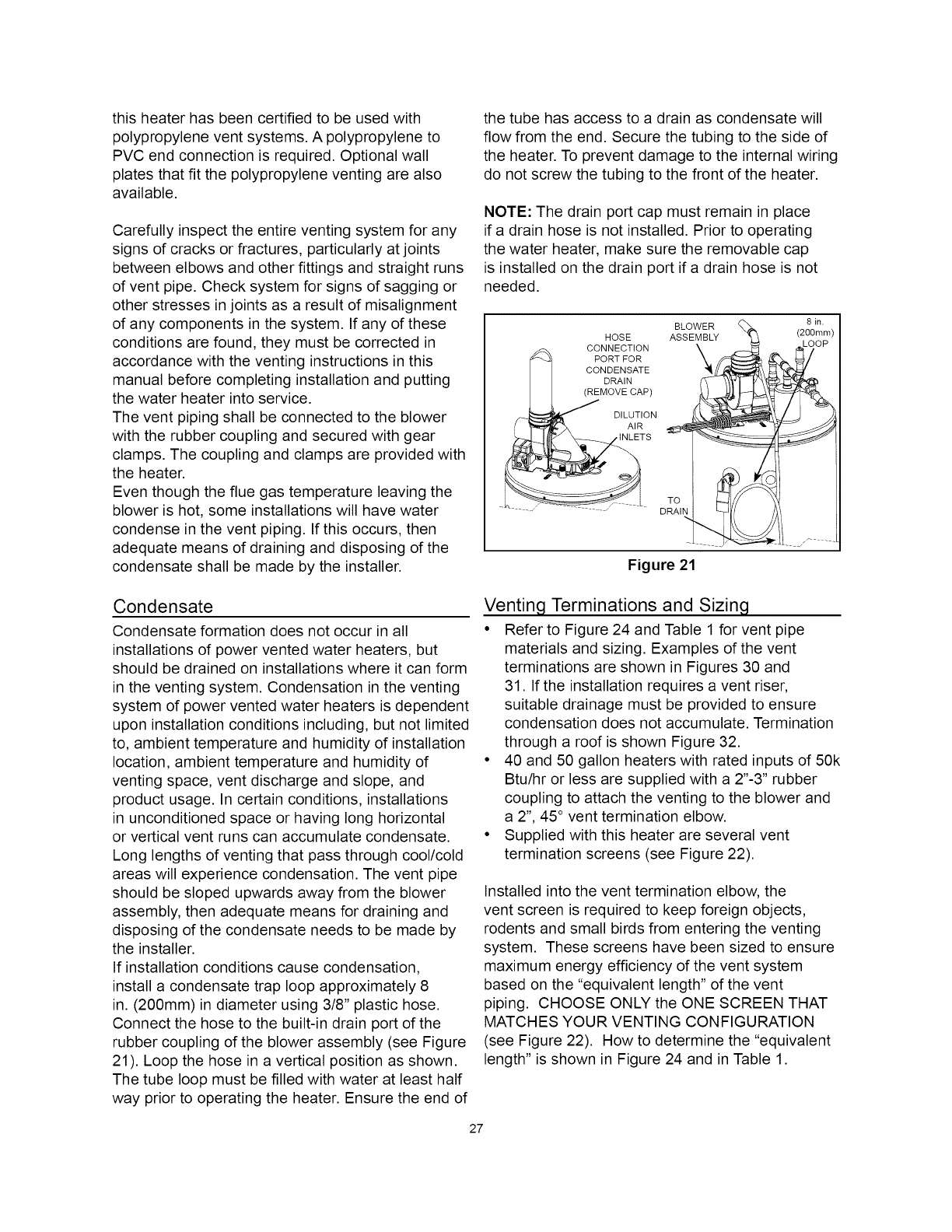
the tube has access to a drain as condensate will
flow from the end. Secure the tubing to the side of
the heater. To prevent damage to the internal wiring
do not screw the tubing to the front of the heater.
NOTE: The drain port cap must remain in place
if a drain hose is not installed. Prior to operating
the water heater, make sure the removable cap
is installed on the drain port if a drain hose is not
needed.
BLOWER (_
HOSE _E_Y
.... CONNECTION
_ ' PORT FOR
CONDENSATE
DRAIN
(REMOVE CAP)
/__ _ DILUTION
I _ AIR
__TS TO
DRAIN
Figure 21
8in.
(200mm)
Condensate
Condensate formation does not occur in all
installations of power vented water heaters, but
should be drained on installations where it can form
in the venting system. Condensation in the venting
system of power vented water heaters is dependent
upon installation conditions including, but not limited
to, ambient temperature and humidity of installation
location, ambient temperature and humidity of
venting space, vent discharge and slope, and
product usage. In certain conditions, installations
in unconditioned space or having long horizontal
or vertical vent runs can accumulate condensate.
Long lengths of venting that pass through cool/cold
areas will experience condensation. The vent pipe
should be sloped upwards away from the blower
assembly, then adequate means for draining and
disposing of the condensate needs to be made by
the installer.
If installation conditions cause condensation,
install a condensate trap loop approximately 8
in. (200mm) in diameter using 3/8" plastic hose.
Connect the hose to the built-in drain port of the
rubber coupling of the blower assembly (see Figure
21). Loop the hose in a vertical position as shown.
The tube loop must be filled with water at least half
way prior to operating the heater. Ensure the end of
Venting Terminations and Sizing
• Refer to Figure 24 and Table 1 for vent pipe
materials and sizing. Examples of the vent
terminations are shown in Figures 30 and
31. If the installation requires a vent riser,
suitable drainage must be provided to ensure
condensation does not accumulate. Termination
through a roof is shown Figure 32.
• 40 and 50 gallon heaters with rated inputs of 50k
Btu/hr or less are supplied with a 2"-3" rubber
coupling to attach the venting to the blower and
a 2", 45° vent termination elbow.
• Supplied with this heater are several vent
termination screens (see Figure 22).
Installed into the vent termination elbow, the
vent screen is required to keep foreign objects,
rodents and small birds from entering the venting
system. These screens have been sized to ensure
maximum energy efficiency of the vent system
based on the "equivalent length" of the vent
piping. CHOOSE ONLY the ONE SCREEN THAT
MATCHES YOUR VENTING CONFIGURATION
(see Figure 22). How to determine the "equivalent
length" is shown in Figure 24 and in Table 1.
27
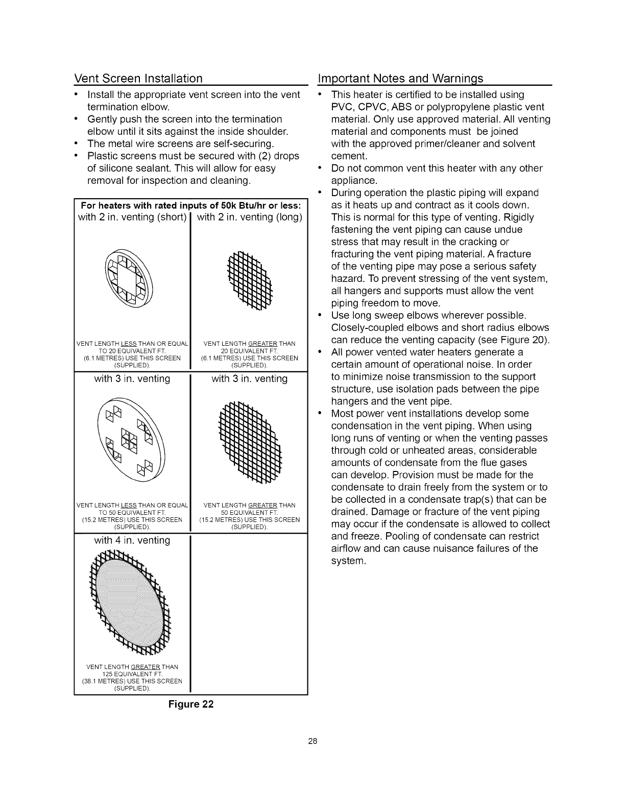
Vent Screen Installation
• Install the appropriate vent screen into the vent
termination elbow.
• Gently push the screen into the termination
elbow until it sits against the inside shoulder.
• The metal wire screens are self-securing.
• Plastic screens must be secured with (2) drops
of silicone sealant. This will allow for easy
removal for inspection and cleaning.
For heaters with rated in
with 2 in. venting (short)
VENT LENGTH LESS THAN OR EQUAL
TO 20 EQUIVALENT FT.
(6.1 METRES) USE THIS SCREEN
(SUPPLIED).
with 3 in. venting
VENT LENGTH LESS THAN OR EQUAL
TO 50 EQUIVALENT FT.
(15.2 METRES) USE THIS SCREEN
(SUPPLIED).
with 4 in. venting
_uts of 50k Btu/hr or less:
with 2 in. venting (long)
VENT LENGTH GREATER THAN
20 EQUIVALENT FT.
(6.1 METRES) USE THIS SCREEN
(SUPPLIED).
with 3 in. venting
VENT LENGTH GREATER THAN
50 EQUIVALENT FT.
(15.2 METRES) USE THIS SCREEN
(SUPPLIED).
VENT LENGTH GREATER THAN
125 EQU IVALENT FT.
(38.1 METRES) USE THIS SCREEN
(SUPPLIED).
Figure 22
Important Notes and Warnings
• This heater is certified to be installed using
PVC, CPVC, ABS or polypropylene plastic vent
material. Only use approved material. All venting
material and components must be joined
with the approved primer/cleaner and solvent
cement.
• Do not common vent this heater with any other
appliance.
• During operation the plastic piping will expand
as it heats up and contract as it cools down.
This is normal for this type of venting. Rigidly
fastening the vent piping can cause undue
stress that may result in the cracking or
fracturing the vent piping material. A fracture
of the venting pipe may pose a serious safety
hazard. To prevent stressing of the vent system,
all hangers and supports must allow the vent
piping freedom to move.
• Use long sweep elbows wherever possible.
Closely-coupled elbows and short radius elbows
can reduce the venting capacity (see Figure 20).
• All power vented water heaters generate a
certain amount of operational noise. In order
to minimize noise transmission to the support
structure, use isolation pads between the pipe
hangers and the vent pipe.
• Most power vent installations develop some
condensation in the vent piping. When using
long runs of venting or when the venting passes
through cold or unheated areas, considerable
amounts of condensate from the flue gases
can develop. Provision must be made for the
condensate to drain freely from the system or to
be collected in a condensate trap(s) that can be
drained. Damage or fracture of the vent piping
may occur if the condensate is allowed to collect
and freeze. Pooling of condensate can restrict
airflow and can cause nuisance failures of the
system.
28
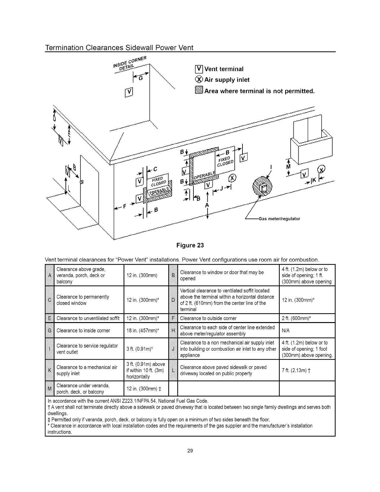
Termination Clearances Sidewall Power Vent
\
\
\
\\
/
[] Vent terminal
(_Air supply inlet
Area where terminal is not permitted.
'& -_ias meter/regulator
Figure 23
Vent terminal clearances for "Power Vent" installations.
Clearance above grade,
veranda, porch, deck or
balcony
Clearance to permanently
closed window
Clearance to unventilated soffit
Clearance to inside corner
Clearance to service regulator
vent outlet
Clearance to a mechanical air
supply inlet
,, Clearance underveranda,
................porch, deck, or balcony
12 in. (300mm)
12 in. (300mm)*
12in.(300mm)*
18in.(457mm)*
3 ft. (0.91m)*
Power Vent configurations use room air for combustion.
Clearance to window or door that may be
opened
Vertical clearance to ventilated soffit located
above the terminal within a horizontal distance
of 2 ft. (610mm) from the center line of the
terminal
Clearanceto outsidecorner
Clearance to each side of center line extended
above meter/regulator assembly
Clearance to a non mechanical air supply inlet
into building or combustion air inlet to any other
appliance
3 ft. (0.91m)above
ifwithin10 ft. (3m)
horizontally
12in.(300mm)
Clearance above paved sidewalk or paved
driveway located on public property
4 ft. (1.2m)belowor to
side of opening;1ft.
(300mm)aboveopening
12 in. (300mm)*
2 ft. (600mm)*
N/A
4 ft. (1.2m)belowor to
side of opening;1foot
(300mm)aboveopening.
7ft. (2.13m)1
In accordance with the current ANSI Z223.1tNFPA 54, National Fuel Gas Code.
1 A vent shall not terminate directly above a sidewalk or paved driveway that is located between two single family dwellings and serves both
dwellings.
Permitted only if veranda, porch, deck, or balcony is fully open on a minimum of two sides beneath the floor.
* Clearance in accordance with local installation codes and the requirements of the gas supplier and the manufacturer's installation
instructions.
29

Calculatin 9 Equivalent Feet
50ft. (15.2m) + 7ft. (2.1m) +
40 & 50 gal. 50,000 2" (50mm) - 0.37 in. w.c termination elbow termination elbow
125 ft. (38.1m) + 7 ft. (2.1m) +
40 & 50 gal. 50,000 3" (76mm) - 0.37 in. w.c. termination elbow termination elbow
180 ft. (54.9m) +
40 & 50 gal. 50,000 4" (102mm) - 0.37 in. w.c. termination elbow 125 ft. (38.1m) +
termination elbow
Equivalent lengths of straight pipe for various elbows using Schedule 40 PVC, CPVC and
polypropylene.
.otes:
.....................................................................................................1. Use long radius elbows where
2" (50ram)
3" (76ram)
4" (102mm)
2" (50ram)
3" (76ram)
4" (102mm)
90° elbow
45° elbow
8 ft. (2.44m)
4 ft. (1.22m)
5 ft. (1.52m)
2.5 ft. (0.76m)
,
3.
possible. Minimum distance
between 90° elbows should be 6"
(150ram) wherever possible.
Venting systems may use a
maximum of five (5) 90 ° elbows.
Use proper screen termination
(see Figure 22).
Table 1
COVER PLATE Note: The vent pipe must be supported every 4 ft. (1.TM). To prevent vibration and sagging, it is recommended to use isolation pads
_DT r,M^_ _ when attach ng straps to f oor jo sts wa s or ce ngs PVC and CPVC vent p pe shoD d be s oped upwards away from the b ower
......... J \ _/ _.v.;l/'' assembly at a pitch of 1/8 in. (3mm i rise per 4 ft. (1.2M). Poiypropylene vent systems require a 1/4" (emm) per I ft. (0.3M) upward
TERMINATION \ ": °Lislope to ensure proper drainage.
ELBOW XX '[_ U U _ U U i _45°SHORIFI
RODENT ," _: ELBOW
SCREEN
(INSTALL INTO "" ,/ / I ]
ELBOW) "'...Jk_[ :.4'u -, D :,
12" (3O5mm)M IN. OR ..:| _/ _,l X _,[_'JC__ B I
ABOVE ANTICIPATED i ] Example for calculating equivalent feet STRAP _- --C _
BNOWLEVEL.' '1us'ngT'venting *,/
':'tBeetion"A"05,t 015m 7
.,",1 90° elbow 80 ft (2 44m) /_ _ I /
."1 SectienB 10ft (031m) 90°SHORT _ ,._..I__ L__ A
__-_ .";I 45° elbow 4.0 ft. (1.22m) ELBOW J
/' ' I Section C 1.5 ft. (0.46m) _ _--
/"'._ 45 ° elbow 4.0 ft. (1.22m)
/"':1 Section D 15.0 ft. (4.57m) (_1_
/". JTotal Equivalent 34.0 ft. (10.37m)
GROUND LEVEL "; | ._
':_"1 Based on this example use the (fully open) rodent
.,".1 screen for vent length greater than 20 equivalent ft
'_1 (6.1 equivalent metres) (see Figures 22).
Figure 24
3O
Vent Pipe Preparation
NOTE: Before preparation see also "Venting
Installation" section.
1. INITIAL PREPARATION
• Make sure the solvent cement you are
planning to use is designed for the specific
application you are attempting.
• Know the physical and chemical
characteristics and limitations of the PVC and
CPVC piping materials that you are about to
use.
• Know the reputation of your manufacturer
and their products.
• Know your own qualifications or those of your
contractor. The solvent welding technique of
joining PVC and CPVC pipe is a specialized
skill just as any other pipe fitting technique.
• Closely supervise the installation and inspect
the finished job before start-up.
• Contact the manufacturer, supplier, or
competent consulting agency if you have any
questions about the application or installation
of PVC and CPVC pipe.
• Take the time and effort to do a professional
job. Shortcuts will only cause you problems
and delays in start-up. By far, the majority of
failures in PVC and CPVC systems are the
result of shortcuts and/or improper joining
techniques.
NOTE: Polypropylene systems are not cemented
together. See separate instructions obtained from
your supplier.
2. SELECTION OF MATERIALS (PVC and CPVC
VENTING)
• Cutting Device - Saw or Pipe Cutter
• Deburring Tool, Knife, File, or Beveling
Machine (2" and above)
• Brush - Pure Bristle
• Rag - Cotton (Not Synthetic)
• Primer and Cleaner
• Solvent Cement - PVC for PVC Components
and CPVC for CPVC Components only
• Containers - Metal or Glass to hold Primer
and Cement. Select the type of PVC or
CPVC materials to be used on the basis of
their application with respect to chemical
resistance, pressure rating, temperature
characteristics, etc.
• Insertion Tool - Helpful for larger diameter
pipe and fittings 6" (152mm) and above
31
Fire or Explosion Hazard
• Do not store or use gasoline or other flammable vapors and
liquids in the vicinity of this or any other appliance.
• Avoid all ignition sources if you smell gas.
• Do not expose water heater control to excessive gas
pressure.
• Use only gas shown on rating plate.
• Maintain required clearances to combustibles.
• Keep ignition sources away from faucets after extended
period of non-use.
l_ Read instruction manual before
installing, using or servicing
water heater.
Primer:
It is recommended that Tetrahydrofuran
(THF) be used to prepare the surfaces of pipe
and fittings for solvent welding. Do not use
water, rags, gasoline or any other substitutes
for cleaning PVC or CPVC surfaces. A
chemical cleaner such as MEK may be used.
Cement:
The cement should be a bodied cement
of approximately 500 to 1600 centipoise
viscosity containing 10-20% (by weight) virgin
PVC material solvated with Tetrahydrofuran
(THF). Small quantities of Dimethyl
Formamide (DMF) may be included to act
as a retarding agent to extend curing time.
Select the proper cement; Schedule 40
cement should be used for Schedule 40 pipe.
Never use all-purpose cements, commercial
glues and adhesives orABS cement to join
PVC or CPVC and s.
iFire Hazard
• Primers and cements are
extremely flammable, and must
not be stored or used near heat
or open flame.
• Also, use only in a well venti-
lated area.
Applicators:
Select a suitable pure bristle type paint brush.
Use a proper width brush or roller to apply
the primer and cement (see chart below).
Speedy application of cement is important
due to its fast drying characteristics.
IMPORTANT NOTE: A dauber type applicator
should only be used on pipe sizes 2" and below.
For larger diameter pipe, a brush or roller must be
used.
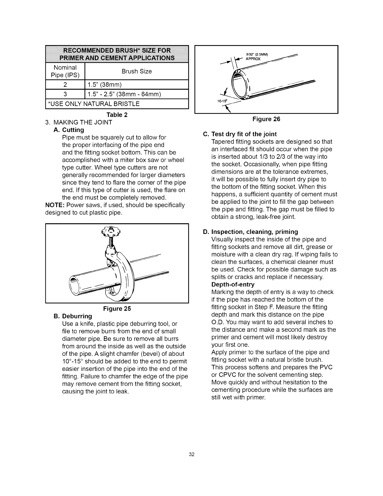
Nominal BrushSize
Pipe(IPS)
2 1.5"(38mm)
3 1.5"- 2.5"(38mm- 64mm)
*USEONLYNATURALBRISTLE
Table2
3. MAKINGTHEJOINT
A. Cutting
Pipemustbesquarelycutto allowfor
theproperinterfacingofthepipeend
andthefittingsocketbottom.Thiscanbe
accomplishedwitha miterboxsaworwheel
typecutter.Wheeltypecuttersarenot
generallyrecommendedforlargerdiameters
sincetheytendtoflarethecornerofthepipe
end.Ifthistypeof cutterisused,theflareon
theendmustbecompletelyremoved.
NOTE:Powersaws,ifused,shouldbespecifically
designedtocutplasticpipe.
B,
Figure 25
Deburring
Use a knife, plastic pipe deburring tool, or
file to remove burrs from the end of small
diameter pipe. Be sure to remove all burrs
from around the inside as well as the outside
of the pipe. A slight chamfer (bevel) of about
10°-15 ° should be added to the end to permit
easier insertion of the pipe into the end of the
fitting. Failure to chamfer the edge of the pipe
may remove cement from the fitting socket,
causing the joint to leak.
C,
D,
10-15 0
Figure 26
Test dry fit of the joint
Tapered fitting sockets are designed so that
an interfaced fit should occur when the pipe
is inserted about 1/3 to 2/3 of the way into
the socket. Occasionally, when pipe fitting
dimensions are at the tolerance extremes,
it will be possible to fully insert dry pipe to
the bottom of the fitting socket. When this
happens, a sufficient quantity of cement must
be applied to the joint to fill the gap between
the pipe and fitting. The gap must be filled to
obtain a strong, leak-free joint.
Inspection, cleaning, priming
Visually inspect the inside of the pipe and
fitting sockets and remove all dirt, grease or
moisture with a clean dry rag. If wiping fails to
clean the surfaces, a chemical cleaner must
be used. Check for possible damage such as
splits or cracks and replace if necessary.
Depth-of-entry
Marking the depth of entry is a way to check
if the pipe has reached the bottom of the
fitting socket in Step F. Measure the fitting
depth and mark this distance on the pipe
O.D. You may want to add several inches to
the distance and make a second mark as the
primer and cement will most likely destroy
your first one.
Apply primer to the surface of the pipe and
fitting socket with a natural bristle brush.
This process softens and prepares the PVC
or CPVC for the solvent cementing step.
Move quickly and without hesitation to the
cementing procedure while the surfaces are
still wet with primer.
32
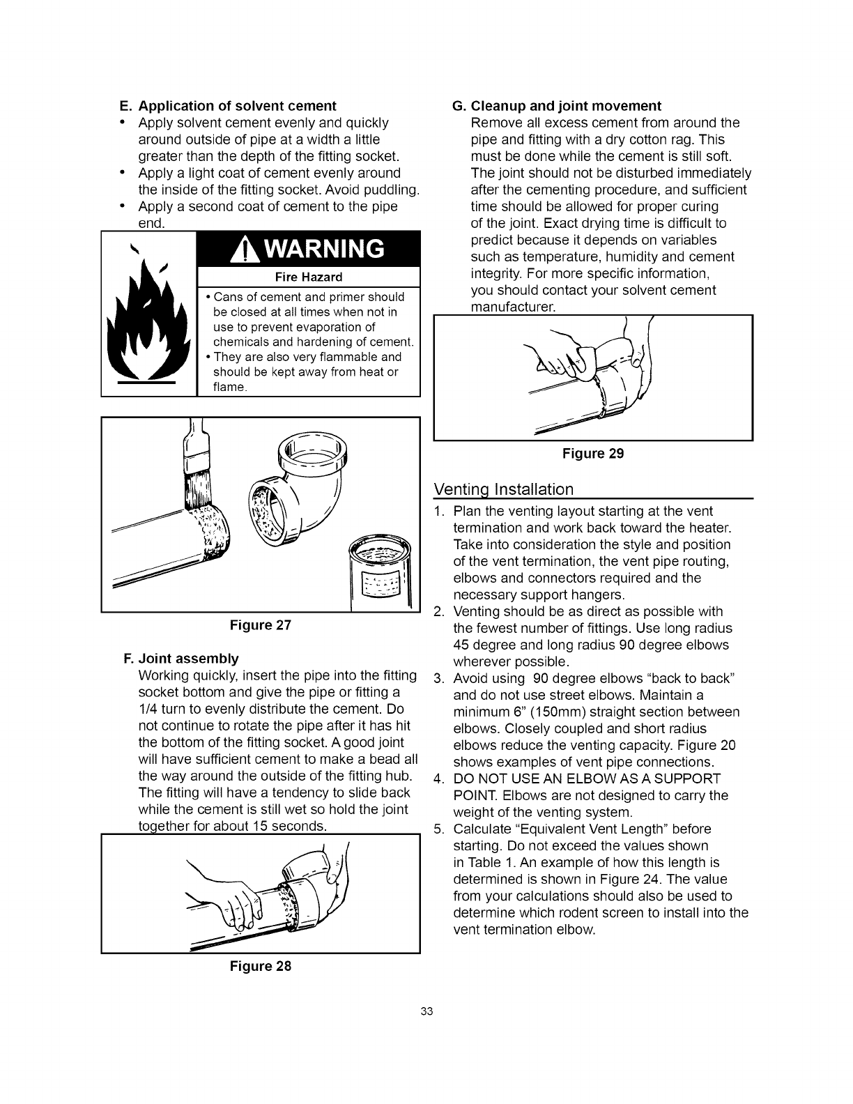
E. Application of solvent cement
• Apply solvent cement evenly and quickly
around outside of pipe at a width a little
greater than the depth of the fitting socket.
• Apply a light coat of cement evenly around
the inside of the fitting socket. Avoid puddling.
• Apply a second coat of cement to the pipe
end.
Fire Hazard
• Cans of cement and primer should
be closed at all times when not in
use to prevent evaporation of
chemicals and hardening of cement.
• They are also very flammable and
should be kept away from heat or
flame.
J
Figure 27
F. Joint assembly
Working quickly, insert the pipe into the fitting
socket bottom and give the pipe or fitting a
1/4 turn to evenly distribute the cement. Do
not continue to rotate the pipe after it has hit
the bottom of the fitting socket. A good joint
will have sufficient cement to make a bead all
the way around the outside of the fitting hub.
The fitting will have a tendency to slide back
while the cement is still wet so hold the joint
together for about 15 seconds.
Figure 28
G, Cleanup and joint movement
Remove all excess cement from around the
pipe and fitting with a dry cotton rag. This
must be done while the cement is still soft.
The joint should not be disturbed immediately
after the cementing procedure, and sufficient
time should be allowed for proper curing
of the joint. Exact drying time is difficult to
predict because it depends on variables
such as temperature, humidity and cement
integrity. For more specific information,
you should contact your solvent cement
manufacturer.
Figure 29
Venting Installation
1. Plan the venting layout starting at the vent
termination and work back toward the heater.
Take into consideration the style and position
of the vent termination, the vent pipe routing,
elbows and connectors required and the
necessary support hangers.
2. Venting should be as direct as possible with
the fewest number of fittings. Use long radius
45 degree and long radius 90 degree elbows
wherever possible.
3. Avoid using 90 degree elbows "back to back"
and do not use street elbows. Maintain a
minimum 6" (150ram) straight section between
elbows. Closely coupled and short radius
elbows reduce the venting capacity. Figure 20
shows examples of vent pipe connections.
4. DO NOT USE AN ELBOW AS A SUPPORT
POINT. Elbows are not designed to carry the
weight of the venting system.
5. Calculate "Equivalent Vent Length" before
starting. Do not exceed the values shown
in Table 1. An example of how this length is
determined is shown in Figure 24. The value
from your calculations should also be used to
determine which rodent screen to install into the
vent termination elbow.
33

6. Measure the vent piping and cut to required
lengths• Pipes must be cut at right angles and
deburred to ensure a good smooth fit with
sufficient overlap for the glue joints• Correct any
interference conditions•
7. Provide support hangers for horizontal vent
piping every 4 ft. (1.2m) to prevent sagging
and stress• Provide a minimum of 1/8" (3mm)
rise per 4 ft. (1.2m) of vent piping to ensure
adequate drainage (polypropylene vent systems
require a 1/4 in. (6mm) rise per 1 ft. (0.3m)
of vent pipe)• Horizontal vent piping must not
sag to form valleys where condensate can
collect• Vertical venting shall be supported
every 5 ft. (1.5m). Use appropriate support
straps and vibration isolators (foam pads) on
straight sections only. Allow sufficient clearance
for expansion and contraction of the venting
system•
8. At the point where the venting exits the building,
cut a 2-1/2" (64mm) hole for 2" (51mm) venting,
a 3-1/2" (89mm) hole for 3" (76mm) venting or a
4-1/2" (114mm) hole for 4" (102mm) venting• For
sidewall applications, use the appropriate metal
cover plate as a template to mark the hole for
the vent pipe to pass through the wall. BEWARE
OF CONCEALED WIRING AND PIPING INSIDE
THE WALL.
9. Insert the vent piping through this hole and
secure into position• Connect the vent pipe to
the end termination elbow as shown in Figures
30-32•
Use of Solvent Cement and Primer
• Use only in well-ventilated areas.
• Do not use near flame or open fire.
• Use only the Solvent Cement and Primer appropriate for
the venting material being used.
• Solvent cements for plastic pipe are flammable liquids and
must be kept away from all sources of ignition.
10. Dry fit all vent pipes, elbows, connectors and
fittings before joining any parts with solvent
cement• PARTS MUST FIT WITHOUT STRESS
OR BENDING OF ANY SECTION and each
connection must overlap a minimum of 1/2"
(13mm). Do not force fit any of the connections•
Use only the appropriate solvent cement•
CAUTION: SOLVENT CEMENTS MAY
PRODUCE FLAMMABLE VAPORS. USE
ONLY IN WELL-VENTILATED AREAS AND
KEEP AWAY FROM ALL SOURCES OF
IGNITION.
NOTE: DO NOT use solvent cement on
polypropylene vent systems•
11. Install the properly sized rodent screen into the
outlet elbow and secure with a small quantity of
silicone sealant.
12.Do not seal the vent piping to the wall until the
venting is properly connected to the blower
assembly.
13.Complete the venting installation by sealing
around the termination assembly where it
passes through the outside wall, inside and out,
with silicone or other suitable sealant.
ATTACH
TERMINATION
ELBOW (MAY
ALSO BE 90 °)
6" (152mm)
.SEALANT
t
12"
(305ram)
MIN.*
!
RODENT
SCREEN
(INSTALL COVER PLATE
tNTO (OPTIONAL)
ELBOW)
GROUND SEALANT
LEVEL* (UNDER
'_ PLATE)
\..
* WHERE SNOW COVER iS NORMAL DURING
VENT PIPING MAY
'."•i.• ':" BE SLOPED IN ANY
•"-..',,• DIRECTION, AS LONG
:' AS A WATER TRAP
"":" ".;" 'IS NOT CREATED
IN THE VENTING
IiI iI!IS STEMT ESO
SHOULD BE KEPT TO
A MINIMUM SOAS
NOT TO EXERT ANY
iUNDUE STRESS ON
.,L.'.,." _HE PIPE.
\
WINTER, ENSURE OUTLET IS INSTALLED ABOVE
ANTICIPATED SNOW LEVEL.
Figure 30
ATTACH BRACKET ---k
TERMINATION _ _,._
ELBOW (MAY _ I
ALSOBE0O°
112 T°w)--
" VENT
(395mm)
MtN*
GROUND
LEVEL* (UNDER
PLATE)
"",'\x,<; ""
._., EQUIVALENT
VENT LENGTH
MEASURED
••"'.." FROM THIS
•:,:POSITION
""" "'" L
.:".:_,." SEALANT
") .'. 2"
VENT PIPING TO BE
SLOPED (DOWN)
TOWARD HEATER
TO PREVENT WATER
FROM COLLECTING
(MAY REQUIRE A
CONDENSATE TEE).
* WHERE SNOW COVER iS NORMAL DURING WINTER,
ENSURE OUTLET iS INSTALLED ABOVE ANTICIPATED
SNOW LEVEL.
Figure 31
34
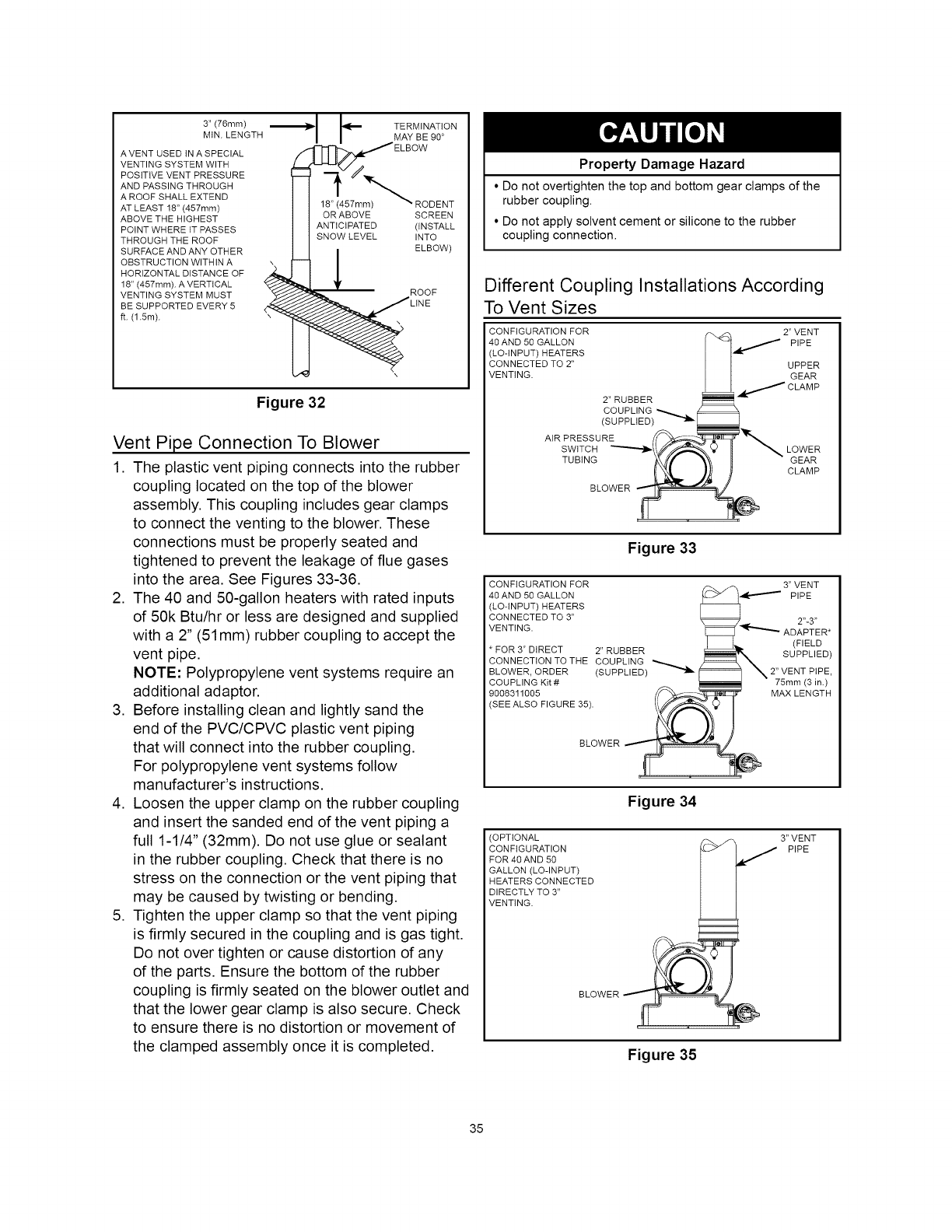
3" (76ram)
MtN. LENGTH
A VENT USED tN A SPECIAL
VENTING SYSTEM WITH
POSITIVE VENT PRESSURE
AND PASSING THROUGH
A ROOF SHALL EXTEND
AT LEAST 18" (457mm)
ABOVE THE HIGHEST
POINT WHERE tT PASSES
THROUGH THE ROOF
SURFACE AND ANY OTHER
OBSTRUCTION WITHIN A
HORIZONTAL DISTANCE OF
18" (457rnm). A VERTICAL
VENTING SYSTEM MUST
BE SUPPORTED EVERY 5
ft. (1.5m).
OR ABOVE
ANTICIPATED
SNOW LEVEL
TERMINATION
MAY BE 90 °
RODENT
SCREEN
(iNSTALL
INTO
ELBOW)
ROOF
Figure 32
Vent Pipe Connection To Blower
1. The plastic vent piping connects into the rubber
coupling located on the top of the blower
assembly. This coupling includes gear clamps
to connect the venting to the blower. These
connections must be properly seated and
tightened to prevent the leakage of flue gases
into the area. See Figures 33-36.
2. The 40 and 50-gallon heaters with rated inputs
of 50k Btu/hr or less are designed and supplied
with a 2" (51 mm) rubber coupling to accept the
vent pipe.
NOTE: Polypropylene vent systems require an
additional adaptor.
3. Before installing clean and lightly sand the
end of the PVC/CPVC plastic vent piping
that will connect into the rubber coupling.
For polypropylene vent systems follow
manufacturer's instructions.
4. Loosen the upper clamp on the rubber coupling
and insert the sanded end of the vent piping a
full 1-1/4" (32mm). Do not use glue or sealant
in the rubber coupling. Check that there is no
stress on the connection or the vent piping that
may be caused by twisting or bending.
5. Tighten the upper clamp so that the vent piping
is firmly secured in the coupling and is gas tight.
Do not over tighten or cause distortion of any
of the parts. Ensure the bottom of the rubber
coupling is firmly seated on the blower outlet and
that the lower gear clamp is also secure. Check
to ensure there is no distortion or movement of
the clamped assembly once it is completed.
Property Damage Hazard
• Do not overtighten the top and bottom gear clamps of the
rubber coupling.
• Do not apply solvent cement or silicone to the rubber
coupling connection.
Different Coupling Installations According
To Vent Sizes
CONFIGURATION FOR 2" VENT
4OAND5OGALLON _ _ PIPE
(LO-INPUT) HEATERS |
CONNECTED TO 2" | UPPER
VENTING. | GEAR
|. /CLAMP
2"RUBBER I"'-
COUPLING _-.._.._. _ 4
(SUPPLtED) f_ ]_'_
Figure 33
3" VENT
PIPE
CONFIGURATION FOR
40AND 50 GALLON
(LO-INPUT) HEATERS
CONNECTED TO 3"
VENTING.
* FOR 3" DIRECT 2" RUBBER
CONNECTION TO THE COUPLING
BLOWER, ORDER (SUPPLIED)
COUPLING Kit#
9008311005
SEE ALSO FIGURE 35).
2"-3"
ADAPTER*
(FIELD
SUPPLIED)
2" VENT PIPE,
75ram (3 in.)
MAX LENGTH
BLOWER
Figure 34
(OPTIONAL 3" VENT
CONFIGURATION J PIPE
FOR 40 AND 50
GALLON (LO-INPUT)
HEATERS CONNECTED
DIRECTLY TO 3"
VENTING.
BLOWER
Figure 35
35
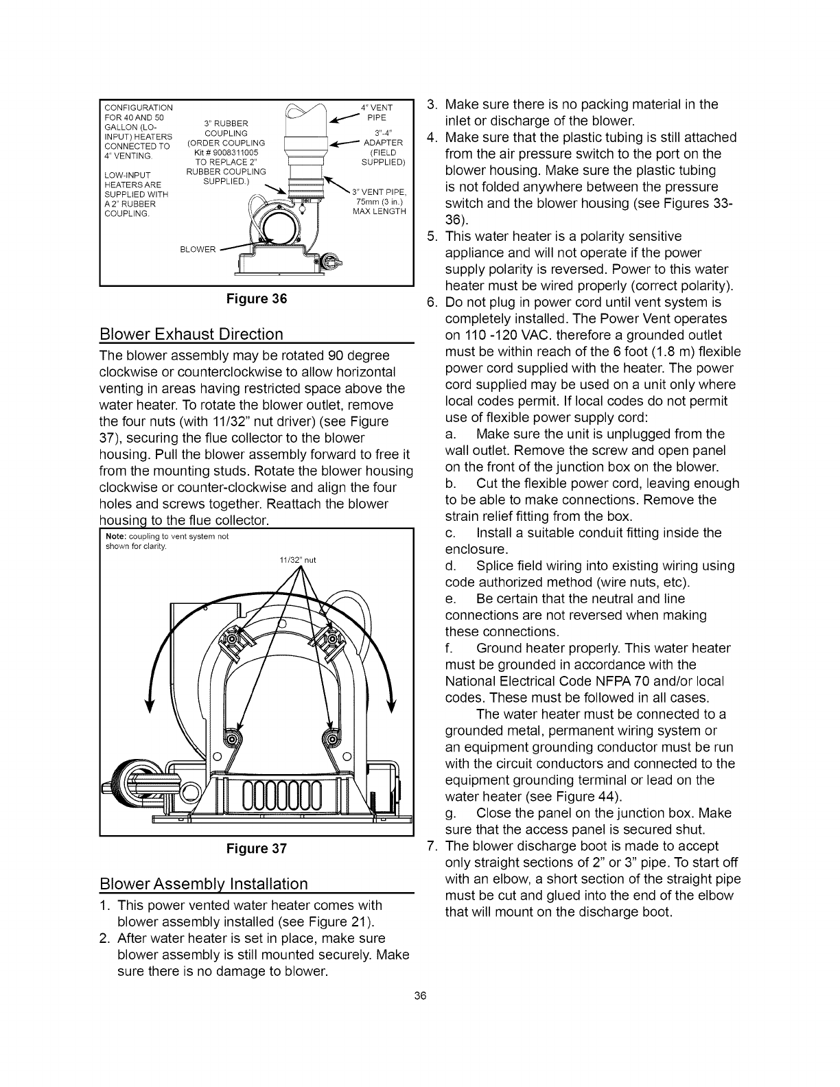
CONFIGURATION 4" VENT
FOR 40AND 50 _._ PIPE
GALLON (LO- 3" RUBBER
INPUT) HEATERS COUPLING 3"-4"
CONNECTED TO (ORDER COUPLING _ ADAPTER
4" VENTING, Kit # 9008311005 (FIELD
TO REPLACE 2" SUPPLIED)
LOW-INPUT RUBBER COUPLING
HEATERS ARE SUPPLIED.)
SUPPLIED WITH :,
A2" RUBBER 75mm (3 in.)
COUPLING. MAX LENGTH
BLOWER
Figure 36
Blower Exhaust Direction
The blower assembly may be rotated 90 degree
clockwise or counterclockwise to allow horizontal
venting in areas having restricted space above the
water heater. To rotate the blower outlet, remove
the four nuts (with 11132" nut driver) (see Figure
37), securing the flue collector to the blower
housing. Pull the blower assembly forward to free it
from the mounting studs. Rotate the blower housing
clockwise or counter-clockwise and align the four
holes and screws together. Reattach the blower
housing to the flue collector.
Note: coupling to vent system not
shown for clarity.
11/32" nut
Figure 37
Blower Assembly Installation
1. This power vented water heater comes with
blower assembly installed (see Figure 21).
2. After water heater is set in place, make sure
blower assembly is still mounted securely. Make
sure there is no damage to blower.
36
3. Make sure there is no packing material in the
inlet or discharge of the blower.
4. Make sure that the plastic tubing is still attached
from the air pressure switch to the port on the
blower housing. Make sure the plastic tubing
is not folded anywhere between the pressure
switch and the blower housing (see Figures 33-
36).
5. This water heater is a polarity sensitive
appliance and will not operate if the power
supply polarity is reversed. Power to this water
heater must be wired properly (correct polarity).
6. Do not plug in power cord until vent system is
completely installed. The Power Vent operates
on 110 -120 VAC. therefore a grounded outlet
must be within reach of the 6 foot (1.8 m) flexible
power cord supplied with the heater. The power
cord supplied may be used on a unit only where
local codes permit. If local codes do not permit
use of flexible power supply cord:
a. Make sure the unit is unplugged from the
wall outlet. Remove the screw and open panel
on the front of the junction box on the blower.
b. Cut the flexible power cord, leaving enough
to be able to make connections. Remove the
strain relief fitting from the box.
c. Install a suitable conduit fitting inside the
enclosure.
d. Splice field wiring into existing wiring using
code authorized method (wire nuts, etc).
e. Be certain that the neutral and line
connections are not reversed when making
these connections.
f. Ground heater properly. This water heater
must be grounded in accordance with the
National Electrical Code NFPA 70 and/or local
codes. These must be followed in all cases.
The water heater must be connected to a
grounded metal, permanent wiring system or
an equipment grounding conductor must be run
with the circuit conductors and connected to the
equipment grounding terminal or lead on the
water heater (see Figure 44).
g. Close the panel on the junction box. Make
sure that the access panel is secured shut.
7. The blower discharge boot is made to accept
only straight sections of 2" or 3" pipe. To start off
with an elbow, a short section of the straight pipe
must be cut and glued into the end of the elbow
that will mount on the discharge boot.
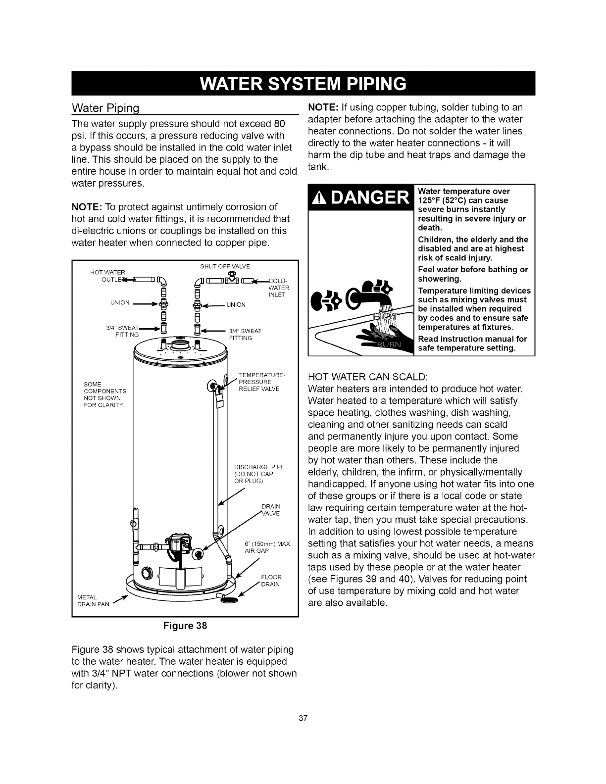
Water Piping
The water supply pressure should not exceed 80
psi. If this occurs, a pressure reducing valve with
a bypass should be installed in the cold water inlet
line. This should be placed on the supply to the
entire house in order to maintain equal hot and cold
water pressures.
NOTE: To protect against untimely corrosion of
hot and cold water fittings, it is recommended that
di-electric unions or couplings be installed on this
water heater when connected to copper pipe.
SOME
COMPONENTS
NOTSHOWN
FOR CLARtT_
METAL
DRAIN PAN °
TEMPERATURE-
J PRESSURE
RELIEF VALVE
DISCHARGE PIPE
(DO NOT CAP
OR PLUG)
7
DRAIN
VALVE
6" (150ram) MAX.
AIR GAP
S FLOOR
JORAIN
Figure 38
Figure 38 shows typical attachment of water piping
to the water heater. The water heater is equipped
with 3/4" NPT water connections (blower not shown
for clarity).
NOTE: If using copper tubing, solder tubing to an
adapter before attaching the adapter to the water
heater connections. Do not solder the water lines
directly to the water heater connections - it will
harm the dip tube and heat traps and damage the
tank.
Water temperature over
125°F (52°C) can cause
severe burns instantly
resulting in severe injury or
death.
Children, the elderly and the
disabled and are at highest
risk of scald injury.
Feel water before bathing or
showering.
Temperature limiting devices
such as mixing valves must
be installed when required
by codes and to ensure safe
temperatures at fixtures.
Read instruction manual for
safe temperature setting.
HOT WATER CAN SCALD:
Water heaters are intended to produce hot water.
Water heated to a temperature which will satisfy
space heating, clothes washing, dish washing,
cleaning and other sanitizing needs can scald
and permanently injure you upon contact. Some
people are more likely to be permanently injured
by hot water than others. These include the
elderly, children, the infirm, or physically/mentally
handicapped. If anyone using hot water fits into one
of these groups or if there is a local code or state
law requiring certain temperature water at the hot-
water tap, then you must take special precautions.
In addition to using lowest possible temperature
setting that satisfies your hot water needs, a means
such as a mixing valve, should be used at hot-water
taps used by these people or at the water heater
(see Figures 39 and 40). Valves for reducing point
of use temperature by mixing cold and hot water
are also available.
37
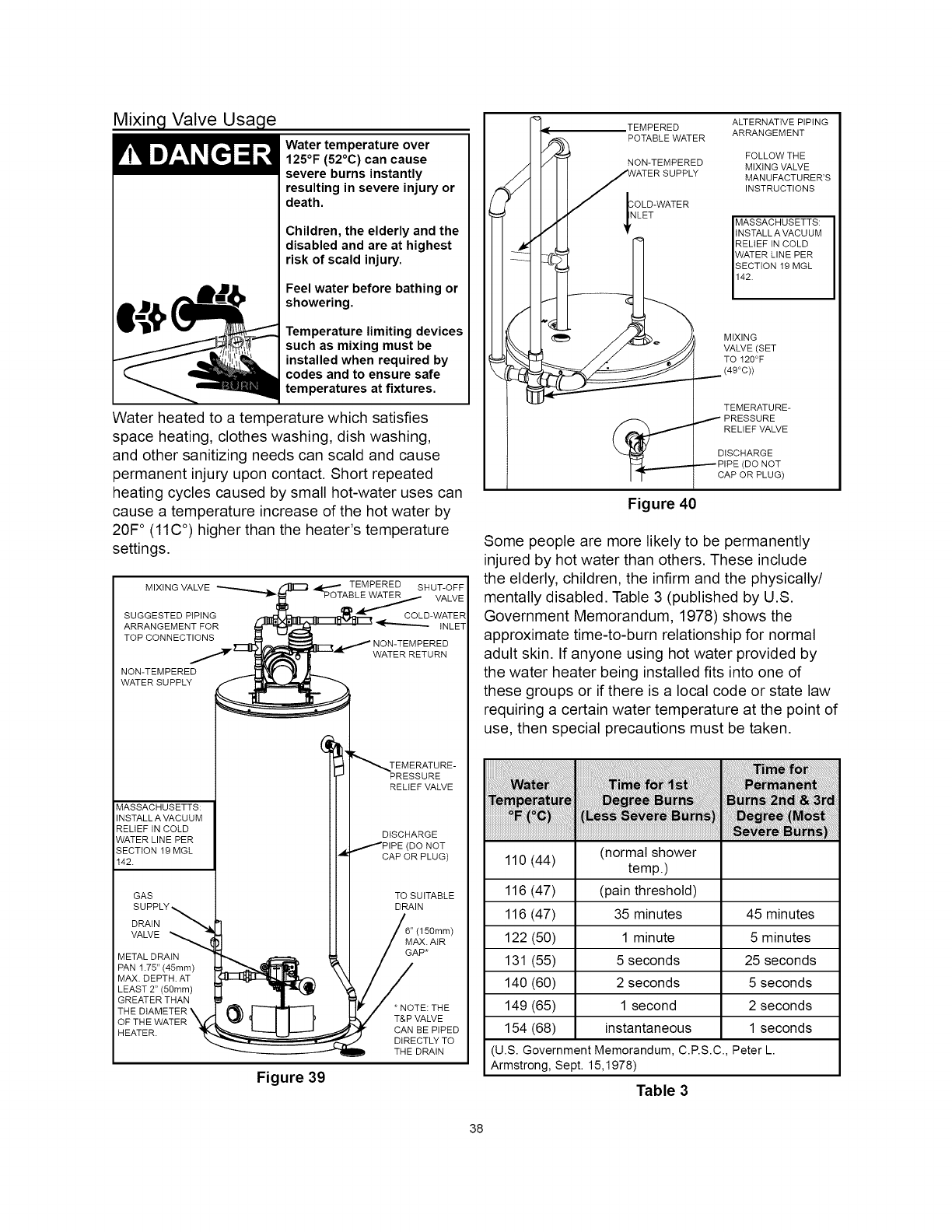
Mixing Valve Usage
Water temperature over
125°F (52°C) can cause
severe burns instantly
resulting in severe injury or
death.
Children, the elderly and the
disabled and are at highest
risk of scald injury.
Feel water before bathing or
showering.
Temperature limiting devices
such as mixing must be
installed when required by
codes and to ensure safe
temperatures at fixtures.
Water heated to a temperature which satisfies
space heating, clothes washing, dish washing,
and other sanitizing needs can scald and cause
permanent injury upon contact. Short repeated
heating cycles caused by small hot-water uses can
cause a temperature increase of the hot water by
20F ° (11C °) higher than the heater's temperature
settings.
MIXING VALVE ---........_ . _ 4p,.._ TEMPERED SHUT_OFF
_1_ PO TAB LE,._,_,._ VALVE
s pSTE f%
TOP CONNECTIONS _ -- LW"'-,,,-_ NwO2_ETREMEPTEuRREND
MASSACHUSETTS:
INSTALL A VACUUM
RELIEF tN COLD
WATER LINE PER
SECTION 19 MGL
142.
GAS
SUPPLY_
DRAIN "_
VALVE _
METAL DRAIN
PAN 1.75" (45mm)
MAX. DEPTH. AT
LEAST 2" (50ram)
GREATER THAN
THE DIAMETER \
OF THE WATER '_t
HEATER.
_TEMERATURE-
PRESSURE
RELtEF VALVE
DISCHARGE
/PIPE (DO NOT
CAP OR PLUG)
TO SUITABLE
DRAIN
_iE 6" (150ram)
AIR
TE: THE
VALVE
BEP/PE?
D THE DRAIN
Figure 39
,TEMPERED
POTABLE WATER
NON-TEMPERED
OLD-WATE R
LET
ALTERNATtVEPIPING
ARRANGEMENT
FOLLOW TH E
MIXING VALVE
MANUFACTURER'S
INSTRUCTIONS
MASSACHUSETTS:
INSTALL A VACU UM
RELIEF IN COLD
WATER LINE PER
SECTION 19 MGL
142.
MIXING
VALVE (SET
TO 120°F
(49°C))
TEMERATURE-
PRESSURE
RELIEF VALVE
DISCHARGE
(DO NOT
CAP OR PLUG)
Figure 40
Some people are more likely to be permanently
injured by hot water than others. These include
the elderly, children, the infirm and the physically/
mentally disabled. Table 3 (published by U.S.
Government Memorandum, 1978) shows the
approximate time-to-burn relationship for normal
adult skin. If anyone using hot water provided by
the water heater being installed fits into one of
these groups or if there is a local code or state law
requiring a certain water temperature at the point of
use, then special precautions must be taken.
110 (44) (normal shower
temp.)
116 (47) (pain threshold)
116 (47) 35 minutes 45 minutes
122 (50) 1 minute 5 minutes
131 (55) 5 seconds 25 seconds
140 (60) 2 seconds 5 seconds
149 (65) 1 second 2 seconds
154 (68) instantaneous 1 seconds
(U.S. Government Memorandum, C.RS.C., Peter L.
Armstrong, Sept. 15,1978)
Table 3
38
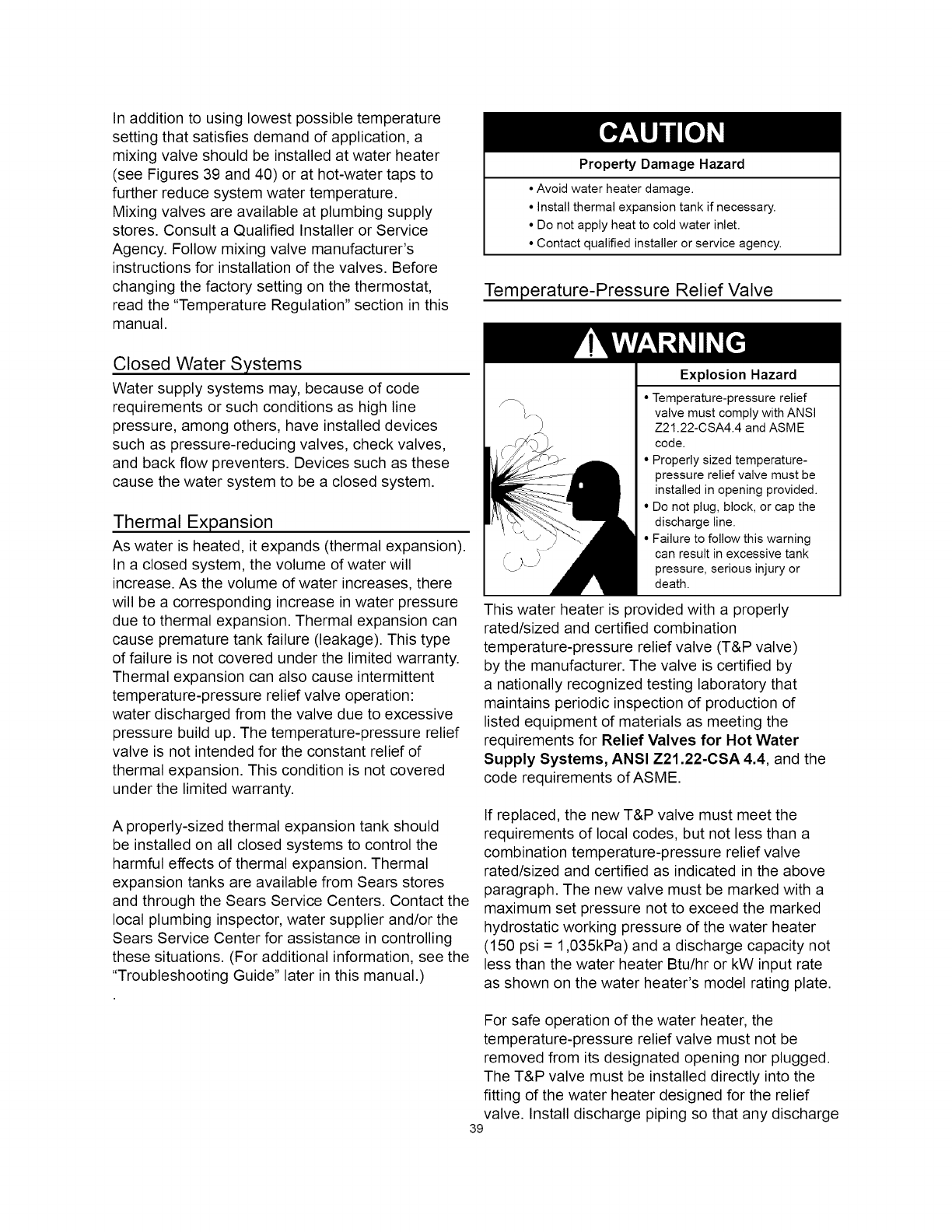
In addition to using lowest possible temperature
setting that satisfies demand of application, a
mixing valve should be installed at water heater
(see Figures 39 and 40) or at hot-water taps to
further reduce system water temperature.
Mixing valves are available at plumbing supply
stores. Consult a Qualified Installer or Service
Agency. Follow mixing valve manufacturer's
instructions for installation of the valves. Before
changing the factory setting on the thermostat,
read the "Temperature Regulation" section in this
manual.
Property Damage Hazard
•Avoid water heater damage.
• Install thermal expansion tank if necessary.
• Do not apply heat to cold water inlet.
• Contact qualified installer or service agency.
Temperature-Pressure Relief Valve
Closed Water Systems
Water supply systems may, because of code
requirements or such conditions as high line
pressure, among others, have installed devices
such as pressure-reducing valves, check valves,
and back flow preventers. Devices such as these
cause the water system to be a closed system.
Thermal Expansion
As water is heated, it expands (thermal expansion).
In a closed system, the volume of water will
increase. As the volume of water increases, there
will be a corresponding increase in water pressure
due to thermal expansion. Thermal expansion can
cause premature tank failure (leakage). This type
of failure is not covered under the limited warranty.
Thermal expansion can also cause intermittent
temperature-pressure relief valve operation:
water discharged from the valve due to excessive
pressure build up. The temperature-pressure relief
valve is not intended for the constant relief of
thermal expansion. This condition is not covered
under the limited warranty.
A properly-sized thermal expansion tank should
be installed on all closed systems to control the
harmful effects of thermal expansion. Thermal
expansion tanks are available from Sears stores
and through the Sears Service Centers. Contact the
local plumbing inspector, water supplier and/or the
Sears Service Center for assistance in controlling
these situations. (For additional information, see the
"Troubleshooting Guide" later in this manual.)
Explosion Hazard
• Temperature-pressure relief
valve must comply with ANSI
Z21.22-CSA4.4 and ASME
code.
• Properly sized temperature-
pressure relief valve must be
installed in opening provided.
• Do not plug, block, or cap the
discharge line.
• Failure to follow this warning
can result in excessive tank
pressure, serious injury or
death.
This water heater is provided with a properly
rated/sized and certified combination
temperature-pressure relief valve (T&P valve)
by the manufacturer. The valve is certified by
a nationally recognized testing laboratory that
maintains periodic inspection of production of
listed equipment of materials as meeting the
requirements for Relief Valves for Hot Water
Supply Systems, ANSI Z21.22-CSA 4.4, and the
code requirements of ASME.
If replaced, the new T&P valve must meet the
requirements of local codes, but not less than a
combination temperature-pressure relief valve
rated/sized and certified as indicated in the above
paragraph. The new valve must be marked with a
maximum set pressure not to exceed the marked
hydrostatic working pressure of the water heater
(150 psi = 1,035kPa) and a discharge capacity not
less than the water heater Btu/hr or kW input rate
as shown on the water heater's model rating plate.
For safe operation of the water heater, the
temperature-pressure relief valve must not be
removed from its designated opening nor plugged.
The T&P valve must be installed directly into the
fitting of the water heater designed for the relief
valve. Install discharge piping so that any discharge
39
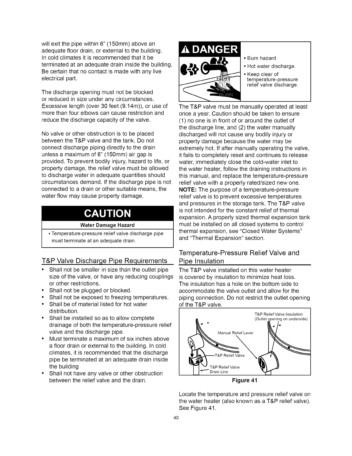
will exit the pipe within 6" (150mm) above an
adequate floor drain, or external to the building.
In cold climates it is recommended that it be
terminated at an adequate drain inside the building.
Be certain that no contact is made with any live
electrical part.
The discharge opening must not be blocked
or reduced in size under any circumstances.
Excessive length (over 30 feet (9.14m)), or use of
more than four elbows can cause restriction and
reduce the discharge capacity of the valve.
No valve or other obstruction is to be placed
between the T&P valve and the tank. Do not
connect discharge piping directly to the drain
unless a maximum of 6" (150mm) air gap is
provided. To prevent bodily injury, hazard to life, or
property damage, the relief valve must be allowed
to discharge water in adequate quantities should
circumstances demand. If the discharge pipe is not
connected to a drain or other suitable means, the
water flow may cause property damage.
Water Damage Hazard
• Temperature-pressure relief valve discharge pipe
must terminate at an adequate drain.
!{I__ ! • Burn hazard.
• Hot water discharge.
• Keep clear of
_I temperature-pressure
relief valve discharge.
The T&P valve must be manually operated at least
once a year. Caution should be taken to ensure
(1) no one is in front of or around the outlet of
the discharge line, and (2) the water manually
discharged will not cause any bodily injury or
property damage because the water may be
extremely hot. If after manually operating the valve,
it fails to completely reset and continues to release
water, immediately close the cold-water inlet to
the water heater, follow the draining instructions in
this manual, and replace the temperature-pressure
relief valve with a properly rated/sized new one.
NOTE: The purpose of a temperature-pressure
relief valve is to prevent excessive temperatures
and pressures in the storage tank. The T&P valve
is not intended for the constant relief of thermal
expansion. A properly sized thermal expansion tank
must be installed on all closed systems to control
thermal expansion, see "Closed Water Systems"
and "Thermal Expansion" section.
T&P Valve Discharge Pipe Requirements
• Shall not be smaller in size than the outlet pipe
size of the valve, or have any reducing couplings
or other restrictions.
• Shall not be plugged or blocked.
• Shall not be exposed to freezing temperatures.
• Shall be of material listed for hot water
distribution.
• Shall be installed so as to allow complete
drainage of both the temperature-pressure relief
valve and the discharge pipe.
• Must terminate a maximum of six inches above
a floor drain or external to the building. In cold
climates, it is recommended that the discharge
pipe be terminated at an adequate drain inside
the building
• Shall not have any valve or other obstruction
between the relief valve and the drain.
Temperature-Pressure Relief Valve and
Pipe Insulation
The T&P valve installed on this water heater
is covered by insulation to minimize heat loss.
The insulation has a hole on the bottom side to
accommodate the valve outlet and allow for the
piping connection. Do not restrict the outlet opening
of the T&P valve.
T&P Relief Valve Insulation
"__X_ever (Outlet "lg on underside)
T&P Relief Valve
I- I _ T&P Relief Valve
H _'''" Drain Line
Figure 41
Locate the temperature and pressure relief valve on
the water heater (also known as a T&P relief valve).
See Figure 41.
4O
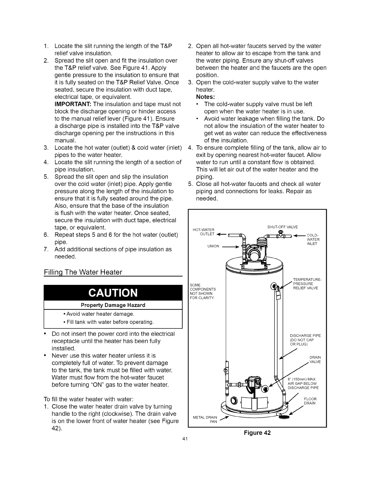
1. Locate the slit running the length of the T&P
relief valve insulation.
2. Spread the slit open and fit the insulation over
the T&P relief valve. See Figure 41. Apply
gentle pressure to the insulation to ensure that
it is fully seated on the T&P Relief Valve. Once
seated, secure the insulation with duct tape,
electrical tape, or equivalent.
IMPORTANT: The insulation and tape must not
block the discharge opening or hinder access
to the manual relief lever (Figure 41 ). Ensure
a discharge pipe is installed into the T&P valve
discharge opening per the instructions in this
manual.
3. Locate the hot water (outlet) & cold water (inlet)
pipes to the water heater.
4. Locate the slit running the length of a section of
pipe insulation.
5. Spread the slit open and slip the insulation
over the cold water (inlet) pipe. Apply gentle
pressure along the length of the insulation to
ensure that it is fully seated around the pipe.
Also, ensure that the base of the insulation
is flush with the water heater. Once seated,
secure the insulation with duct tape, electrical
tape, or equivalent.
6. Repeat steps 5 and 6 for the hot water (outlet)
pipe.
7. Add additional sections of pipe insulation as
needed.
Filling The Water Heater
Property Damage Hazard
•Avoid water heater damage.
• Fill tank with water before operating.
Do not insert the power cord into the electrical
receptacle until the heater has been fully
installed.
Never use this water heater unless it is
completely full of water. To prevent damage
to the tank, the tank must be filled with water.
Water must flow from the hot-water faucet
before turning "ON" gas to the water heater.
To fill the water heater with water:
1. Close the water heater drain valve by turning
handle to the right (clockwise). The drain valve
is on the lower front of water heater (see Figure
42).
2. Open all hot-water faucets served by the water
heater to allow air to escape from the tank and
the water piping. Ensure any shut-off valves
between the heater and the faucets are the open
position.
3. Open the cold-water supply valve to the water
heater.
Notes:
• The cold-water supply valve must be left
open when the water heater is in use.
• Avoid water leakage when filling the tank. Do
not allow the insulation of the water heater to
get wet as water can reduce the effectiveness
of the insulation.
4. To ensure complete filling of the tank, allow air to
exit by opening nearest hot-water faucet. Allow
water to run until a constant flow is obtained.
This will let air out of the water heater and the
piping.
5. Close all hot-water faucets and check all water
piping and connections for leaks. Repair as
needed.
SHUT-OFF VALVE
HOT-WATER
OUTLET 1[ _,_ COLD-
WATER
INLET
UNION
SOME
COMPONENTS
NOTSHOWN
FOR CLARIT_
TEMPERATURE-
RELtEF VALVE
DtSCHARGEPIPE
(DO NOT CAP
OR PLUG)
DRAIN
MAX.
AIR GAP BELOW
DISCHARGEPIPE
FLOOR
DRAIN
METAL DRAIN
PAN
Figure 42
41
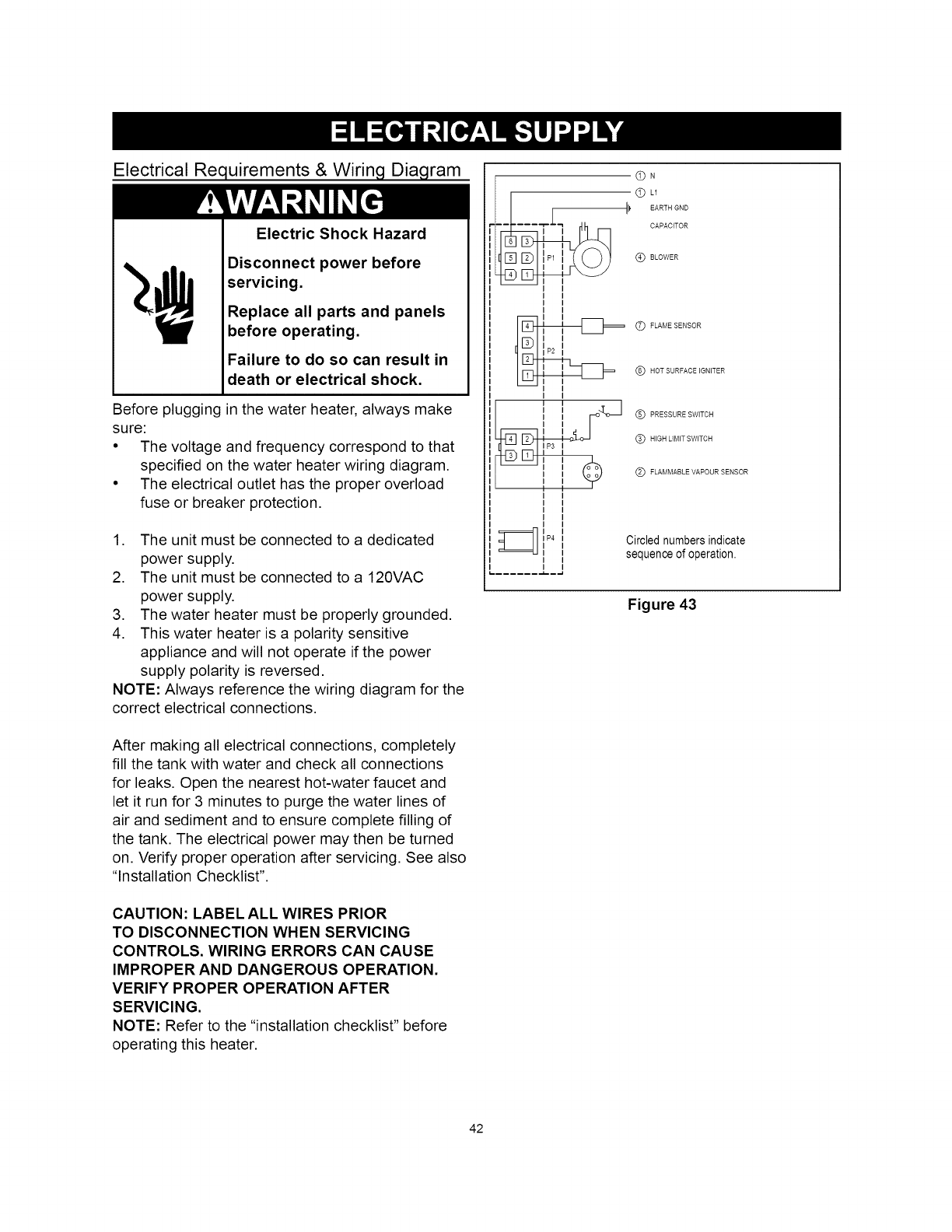
Electrical Requirements & Wiring Diagram
Electric Shock Hazard
Disconnect power before
servicing.
Replace all parts and panels
before operating.
Failure to do so can result in
death or electrical shock,
Before plugging in the water heater, always make
sure:
• The voltage and frequency correspond to that
specified on the water heater wiring diagram.
• The electrical outlet has the proper overload
fuse or breaker protection.
1. The unit must be connected to a dedicated
power supply.
2. The unit must be connected to a 120VAC
power supply.
3. The water heater must be properly grounded.
4. This water heater is a polarity sensitive
appliance and will not operate if the power
supply polarity is reversed.
NOTE: Always reference the wiring diagram for the
correct electrical connections.
After making all electrical connections, completely
fill the tank with water and check all connections
for leaks. Open the nearest hot-water faucet and
let it run for 3 minutes to purge the water lines of
air and sediment and to ensure complete filling of
the tank. The electrical power may then be turned
on. Verify proper operation after servicing. See also
"Installation Checklist".
CAUTION: LABEL ALL WIRES PRIOR
TO DISCONNECTION WHEN SERVICING
CONTROLS. WIRING ERRORS CAN CAUSE
IMPROPER AND DANGEROUS OPERATION.
VERIFY PROPER OPERATION AFTER
SERVICING.
NOTE: Refer to the "installation checklist" before
operating this heater.
©n
© L1
_1_ EARTH GND
- CAPACITOR
© SLOWER
I I
I I
I I
I I
II1_11 C) FLAME SENSOR
@ HOT SURFACE IGNITER
(_ PRESSURE SWITCH
© HiGH LIMITSWITCH
(_) FLAMMABLEVAPOURSENSOR
Circled numbers indicate
sequence of operation.
Figure 43
42
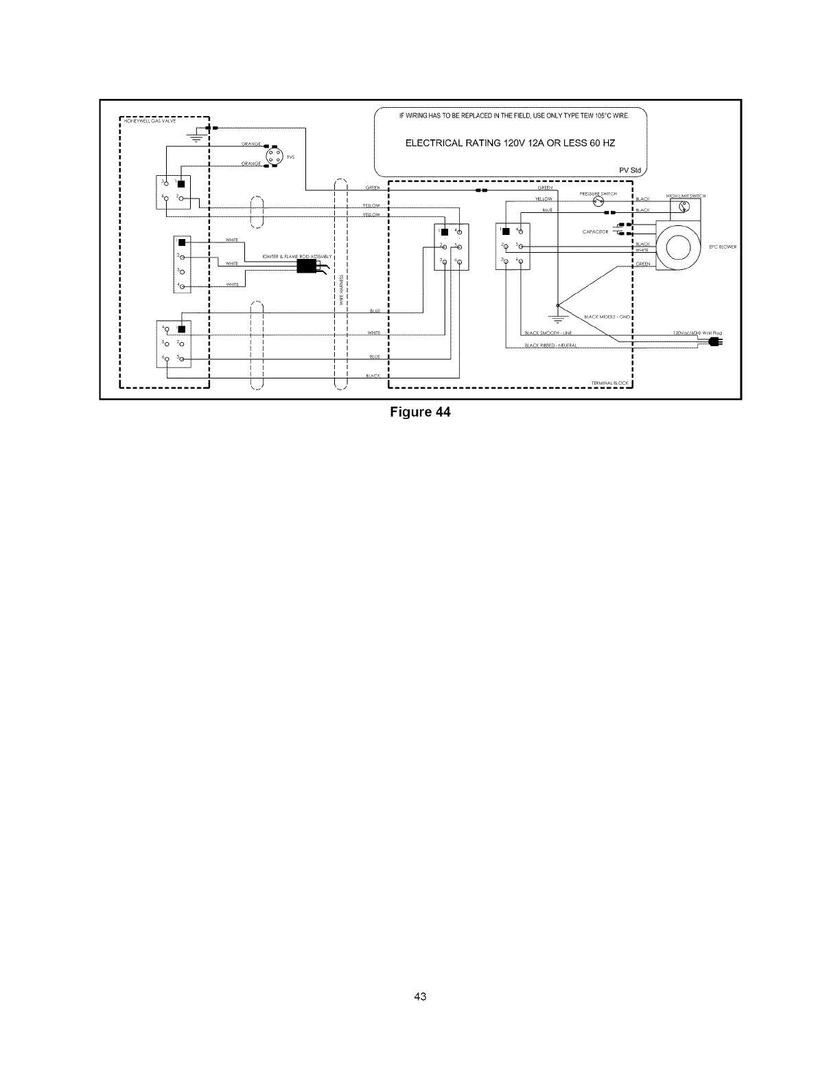
iF WIRING HAS TO BEREPLACED iN THE FIELD, USE ONLY TYPE TEW 105°C WiRE
ELECTRICAL RATING 120V 12A OR LESS 60 HZ
_. PV Stdj
G_N =1111=
,I ] _uf ,
!1 I
' II ',', .....
!
' II ',',
I
!1 I I ii BUE !
I II ',, ',
| I I I I m_c_ I
jI j L) I
-]
4(
6( m
_11 _<
) <s{
OnE_N I
I PRESSU_SWlTC_ H "H >M W;_
BLOE
= _BLACK
_ C_PAC_TOR_
I _LACK
I I WH' EPCBLOWER
BLaCKSM I_0V_C/_0_
maCKRIB_EDHEUTRat I _
1
!
I
!
TERM_AL_LOC_]
Figure 44
43

This water heater has several lockout features
designed to prevent the heater from operating in
unsafe conditions.
System Status LED Indicator Light
The gas control valve/thermostat (see Figure 1,
item 5) controls and monitors the operation and
safety functions of this water heater. Located on
the front of this control is the ON/OFF switch, the
temperature setting dial and the LED indicator light
(see Figure 47). When energized, this light displays
a sequence of flashes that indicates the operational
status of the water heater. If there is a system
safety shutdown, the LED indicator will present a
flash code to alert the problem. See "System Status
And Error Codes" and "Reading The LED Flash
Sequence".
High Limit Controls (Energy Cut Off)
Thermostat/Water Temperature
This feature is a part of the gas control valve/
thermostat (see Figure 1, item 5) and limits the
maximum water temperature. In the event of the
water overheating, this safety feature shuts off the
fuel supply to the burner.
Blower High Limit Switch
This device (see Figure 4, Item 31)is located on
the blower and limits the maximum temperature of
the blower. If the blower temperature rises above
the temperature setting, the switch opens causing
the heater to shut down. The switch will auto reset
once the temperature drops sufficiently.
Blower Air Pressure Switch
This device (see Figure 4, Item 32), located in the
junction box, monitors the air pressure produced
by the blower. In the event that the exhaust venting
becomes blocked or sufficiently restricted, the
switch will shut the heater down.
Flammable Vapor Sensor
When using a gas fired water heater there is a
risk of flammable vapors entering the combustion
chamber, being ignited by the burner flame and
causing a flashback. In order to detect such
flammable vapors before they enter the combustion
chamber, this water heater is equipped with a
flammable vapor sensor (FVS). It is a chemical-
absorption based sensor that is connected to the
gas control/thermostat (see Figure 45). When
exposed to flammable vapors it will trigger the
control to stop the flow of gas and enter the FVS
lockout state. While in the FVS lockout state the
LED on the control will flash the gas lockout code.
(Refer to the "System Status And Error Codes"
section of this manual for an explanation of the
codes applicable to the control installed on your
water heater.) If this error occurs, check around the
water heater for sources of chemical contamination
such as: flammable vapors including gas vapors,
solvents, paint and thinners as well as sources of
water and detergents.
NOTE: Resetting the heater will reset the FVIR
circuit if all sources of contamination have been
removed and the sensor clears. If all sources of
contamination have been removed and the system
will not reset, the sensor will need to be replaced
(see "Resetting the Heater Control").
If there is a problem with the wiring of the
flammable vapor sensor or the flammable vapor
interface, the LED will flash the failure status code
(see "System Status And Error Codes").
* ROTATE LEFT (CCW) TO
REMOVE
COVER*
MOU# NG
BRACKET
FLAMMABLE VAPOR
SENSOR (PULL TO
REMOVE)
Figure 45
44
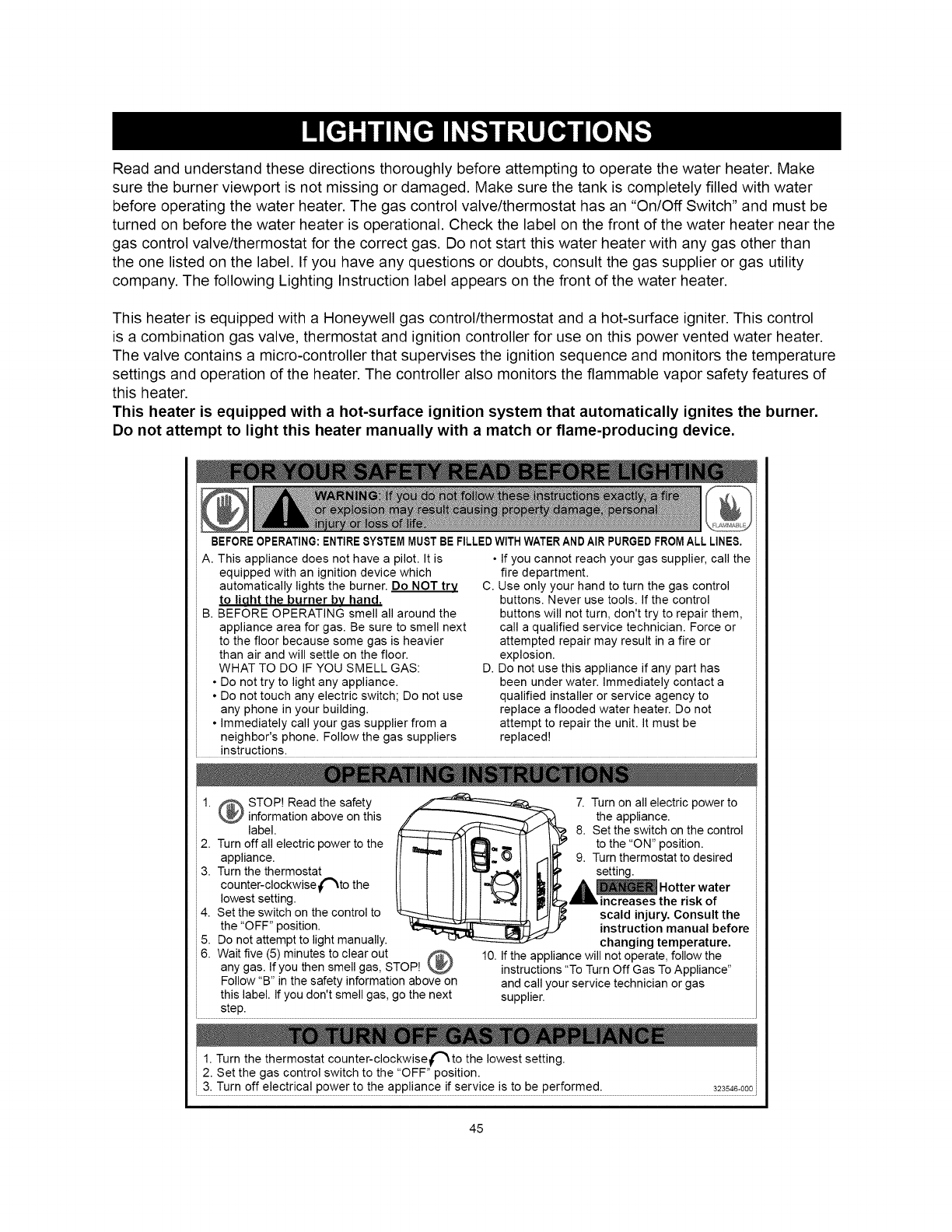
Read and understand these directions thoroughly before attempting to operate the water heater. Make
sure the burner viewport is not missing or damaged. Make sure the tank is completely filled with water
before operating the water heater. The gas control valve/thermostat has an "On/Off Switch" and must be
turned on before the water heater is operational. Check the label on the front of the water heater near the
gas control valve/thermostat for the correct gas. Do not start this water heater with any gas other than
the one listed on the label. If you have any questions or doubts, consult the gas supplier or gas utility
company. The following Lighting Instruction label appears on the front of the water heater.
This heater is equipped with a Honeywell gas control/thermostat and a hot-surface igniter. This control
is a combination gas valve, thermostat and ignition controller for use on this power vented water heater.
The valve contains a micro-controller that supervises the ignition sequence and monitors the temperature
settings and operation of the heater. The controller also monitors the flammable vapor safety features of
this heater.
This heater is equipped with a hot-surface ignition system that automatically ignites the burner.
Do not attempt to light this heater manually with a match or flame-producing device.
BEFOREOPERATING:ENTIRESYSTEMMUSTBE FILLEDWITHWATERANDAIRPURGEDFROMALL LINES,
A. This appliance does not have a pilot. It is • If you cannot reach your gas supplier, call the
equipped with an ignition device which
automatically lights the burner. Do NOT try
to lioht the burner bv hand.
B. BEFORE OPERATING smell all around the
appliance area for gas. Be sure to smell next
to the floor because some gas is heavier
than air and will settle on the floor.
WHAT TO DO IF YOU SMELL GAS:
• Do not try to light any appliance.
• Do not touch any electric switch; Do not use
any phone in your building.
• Immediately call your gas supplier from a
neighbor's phone. Follow the gas suppliers
fire department.
C. Use only your hand to turn the gas control
buttons. Never use tools. If the control
buttons will not turn, don't try to repair them,
call a qualified service technician. Force or
attempted repair may result in a fire or
explosion.
D. Do not use this appliance if any part has
been under water. Immediately contact a
qualified installer or service agency to
replace a flooded water heater. Do not
attempt to repair the unit. It must be
replaced!
= instructions.
1. _ STOP! Read the safety
information above on this
label. I
2. Turn off all electric power to the
appliance.
3. Turn the thermostat
cou nter-clockwise C'_to the
lowest setting.
4. Set the switch on the control to
the "OFF" position.
5. Do not attempt to light manually.
6.
7. Turn on all electric power to
the appliance.
_ 8. Set the switch on the control
to the "ON" position.
9. Turn thermostat to desired
setting.
A _ Hotter water
ll, increases the risk of
scald injury. Consult the
instruction manual before
changing temperature.
Wait five (5) minutes to clear out _ 10. If the appliance will not operate, follow the
any gas. If you then smell gas, STOP! _ instructions "To Turn Off Gas To Appliance"
Follow "B" in the safety information above on and call your service technician or gas
this label. If you don't smell gas, go the next supplier.
step.
i 1. Turn the thermostat counter-clockwise("_to the lowest setting.
i 2. Set the gas control switch to the "OFF" position.
i 3: Turn off e!ectr!ca! power to the app!!ance !f serv!ce !s to be performed: 323s46:o00,
45

Water Heater Operation
Figure 46 shows the water heater's sequence
of operation when a call for heat is initiated. The
ignition control module will attempt to light the
burner three times. If the ignition control does not
detect ignition it will enter lockout mode and flash
the corresponding error code.
HEATER CONTROL
CHECKS TO ENSURE
BLOWER PRESSURE
SWITCH IS OPEN
BLOWER IS J
ENERGIZED
CONTROL CHECKS
TO ENSURE PRES-
SURE SWITCH CLOSES
INDICATING BLOWER
IS OPERATING AND
THERE ARE NO
VENTING BLOCKAGES
(INLET OR OUTLET)
IGNITER IS ENERGIZED
AND MAIN GAS VALVE
IS OPENED
MAIN BURNER COMES
ON AND THE FLAME IS
SENSED BY CONTROL
MAIN BURNER CONTIN-
UES TILL THE WATER
IN THE TANK REACHES
THERMOSTAT SETTING
MAIN BURNER SHUTS
OFF. BLOWER
CONTINUES FORA
POST PURGE TIME
Figure 46
Temperature Regulation
It is recommended that lower water temperatures
be used to avoid the risk of scalding. It is further
recommended, in all cases, that the water
temperature be set for the lowest temperature
which satisfies your hot-water needs. This will also
provide the most energy efficient operation of the
water heater. Short repeated heating cycles caused
by small hot-water uses can cause a temperature
increase of the hot water by 20F ° (11C °) higher
than the heater's temperature settings. If you
experience this type of use you should consider
using lower temperature settings to reduce scald
hazards. Should overheating occur or the gas
supply fails to shut off, turn off the main manual gas
shut off valve to the appliance (see Figure 1)
Water temperature over
125°F (52°C) can cause
severe burns instantly
resulting in severe injury or
death.
Children, the elderly and the
disabled and are at highest
risk of scald injury.
Feel water before bathing or
showering.
Temperature limiting devices
such as mixing valves must
be installed when required
by codes and to ensure safe
temperatures at fixtures.
Read instruction manual for
safe temperature setting.
HOT WATER CAN SCALD:
Water heaters are intended to produce hot water.
Water heated to a temperature which will satisfy
space heating, clothes washing, dish washing, and
other sanitizing needs can scald and permanently
injure you upon contact. Some people are more
likely to be permanently injured by hot water than
others. These include the elderly, children, the
infirm or physically/mentally handicapped. If anyone
using hot water from this heater fits into one of
these groups or if there is a local code or state law
requiring certain temperature water at the hot-water
tap, then you must take special precautions. In
addition to using the lowest possible temperature
setting that satisfies your hot-water needs, a means
such as a mixing valve should be used at the hot-
water taps used by these people or at the water
heater. Mixing valves are available at plumbing
supply or hardware stores (see Figure 39 and 40).
Follow manufacturer's instructions for installation of
the valves. Before changing the factory setting on
the thermostat, in this manual, see Table 4.
The water heater should be located in an area
where the general public does not have access. If
a suitable area is not available, a cover should be
installed over the thermostat to prevent tampering.
This water heater is equipped with an adjustable
thermostat to control water temperature (see Figure
47). Hot water temperatures required for automatic
46
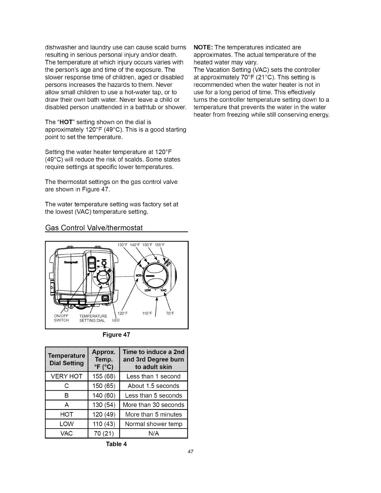
dishwasher and laundry use can cause scald burns
resulting in serious personal injury and/or death.
The temperature at which injury occurs varies with
the person's age and time of the exposure. The
slower response time of children, aged or disabled
persons increases the hazards to them. Never
allow small children to use a hot-water tap, or to
draw their own bath water. Never leave a child or
disabled person unattended in a bathtub or shower.
The "HOT" setting shown on the dial is
approximately 120°F (49°C). This is a good starting
point to set the temperature.
Setting the water heater temperature at 120°F
(49°C) will reduce the risk of scalds. Some states
require settings at specific lower temperatures.
The thermostat settings on the gas control valve
are shown in Figure 47.
The water temperature setting was factory set at
the lowest (VAC) temperature setting.
Gas Control Valve/thermostat
130°F 140°F 150°F 155°F
NOTE: The temperatures indicated are
approximates. The actual temperature of the
heated water may vary.
The Vacation Setting (VAC) sets the controller
at approximately 70°F (21°C). This setting is
recommended when the water heater is not in
use for a long period of time. This effectively
turns the controller temperature setting down to a
temperature that prevents the water in the water
heater from freezing while still conserving energy.
120°F 110°F 70°F
ON/OFF TEMPERATURE
SWITCH SETTING DIAL LED
Figure 47
VERY HOT 155 (68) Less than 1 second
C 150 (65) About 1.5 seconds
B 140 (60) Less than 5 seconds
A 130 (54) More than 30 seconds
HOT 120 (49) More than 5 minutes
LOW 110 (43) Normal shower temp
VAC 70 (21) N/A
Table 4
47
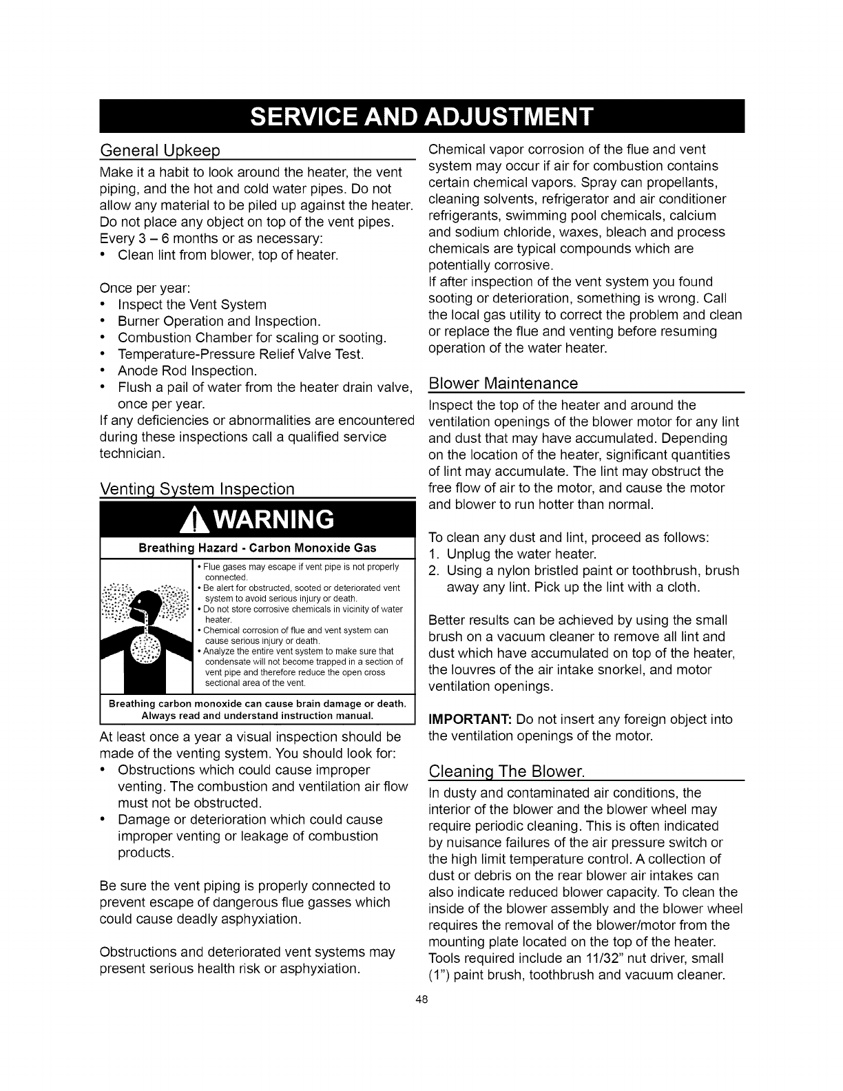
General Upkeep
Make it a habit to look around the heater, the vent
piping, and the hot and cold water pipes. Do not
allow any material to be piled up against the heater.
Do not place any object on top of the vent pipes.
Every 3 - 6 months or as necessary:
• Clean lint from blower, top of heater.
Once per year:
• Inspect the Vent System
• Burner Operation and Inspection.
• Combustion Chamber for scaling or sooting.
• Temperature-Pressure Relief Valve Test.
• Anode Rod Inspection.
• Flush a pail of water from the heater drain valve,
once per year.
If any deficiencies or abnormalities are encountered
during these inspections call a qualified service
technician.
Venting System Inspection
BreathingHazard- Carbon Monoxide Gas
• Flue gases may escape if vent pipe is not properly
connected.
• Be alert for obstructed, sooted or deteriorated vent
system to avoid serious injury or death.
• Do not store corrosive chemicals in vicinity of water
heater.
• Chemical corrosion of flue and vent system can
cause serious injury or death.
• Analyze the entire vent system to make sure that
condensate will not become trapped in a section of
vent pipe and therefore reduce the open cross
sectional area of the vent.
Breathing carbon monoxide can cause brain damage or death.
Always read and understand instruction manual.
At least once a year a visual inspection should be
made of the venting system. You should look for:
• Obstructions which could cause improper
venting. The combustion and ventilation air flow
must not be obstructed.
• Damage or deterioration which could cause
improper venting or leakage of combustion
products.
Be sure the vent piping is properly connected to
prevent escape of dangerous flue gasses which
could cause deadly asphyxiation.
Obstructions and deteriorated vent systems may
present serious health risk or asphyxiation.
Chemical vapor corrosion of the flue and vent
system may occur if air for combustion contains
certain chemical vapors. Spray can propellants,
cleaning solvents, refrigerator and air conditioner
refrigerants, swimming pool chemicals, calcium
and sodium chloride, waxes, bleach and process
chemicals are typical compounds which are
potentially corrosive.
If after inspection of the vent system you found
sooting or deterioration, something is wrong. Call
the local gas utility to correct the problem and clean
or replace the flue and venting before resuming
operation of the water heater.
Blower Maintenance
Inspect the top of the heater and around the
ventilation openings of the blower motor for any lint
and dust that may have accumulated. Depending
on the location of the heater, significant quantities
of lint may accumulate. The lint may obstruct the
free flow of air to the motor, and cause the motor
and blower to run hotter than normal.
To clean any dust and lint, proceed as follows:
1. Unplug the water heater.
2. Using a nylon bristled paint or toothbrush, brush
away any lint. Pick up the lint with a cloth.
Better results can be achieved by using the small
brush on a vacuum cleaner to remove all lint and
dust which have accumulated on top of the heater,
the Iouvres of the air intake snorkel, and motor
ventilation openings.
IMPORTANT: Do not insert any foreign object into
the ventilation openings of the motor.
Cleaning The Blower.
In dusty and contaminated air conditions, the
interior of the blower and the blower wheel may
require periodic cleaning. This is often indicated
by nuisance failures of the air pressure switch or
the high limit temperature control. A collection of
dust or debris on the rear blower air intakes can
also indicate reduced blower capacity. To clean the
inside of the blower assembly and the blower wheel
requires the removal of the blower/motor from the
mounting plate located on the top of the heater.
Tools required include an 11/32" nut driver, small
(1") paint brush, toothbrush and vacuum cleaner.
48

1. Turn the thermostat on the gas control to the
lowest setting. If the heater is running, wait for it
to shut down (see Figure 47).
2. Turn the gas control switch to the "OFF" position.
3. Disconnect the electrical power to the water
heater from the wall outlet.
4. Disconnect the vent piping from the top of the
blower. Loosen the lower gear clamp that holds
the rubber coupling to the blower (see Figure
48).
5. Remove and retain the (4) 11/32" nuts located
on the back of the blower with the nutdriver (see
Figure 37).
6. Holding the blower motor and the blower
housing, pull the assembly forward to disengage
it from the mounting plate. The blower will still be
connected to the junction box so exercise care
not to stress the wiring.
7. Accessing the blower wheel through the outlet,
use the paint brush to brush off the outer edge of
the blower wheel to dislodge the dirt stuck on the
blades and the inside of the housing. Rotate the
wheel until all blades are clear.
NOTE: The wheel is a balanced component. Do
not bend, dent or distort the blades as this can
upset the wheel balance and affect the blower
operation. Vacuum out the loosened dirt.
8. Accessing the inside of the blower wheel through
the rear of the housing, gently brush off the
inside of the blades using the toothbrush. Again,
take care not to distort the blades. Rotate the
wheel until all blades are cleaned and vacuum
the debris.
9. Inspect the flue collector hood (still attached to
the heater) and vacuum out the dust and debris
that may have accumulated.
10.With all parts cleaned and the blower wheel
turning freely, reinstall the blower to the
mounting plate aligning the (4) studs and pushing
tight against the mounting plate.
11.Reinstall the (4) 11/32" nuts and tighten securely.
All (4) nuts must be in place and secure to safely
operate the blower.
12. Reattach the vent piping and coupling to the top
of the blower, tighten the bottom gear clamp and
ensure the piping is secure.
13.With all components clean and secure,
reconnect the electrical power to the heater.
14. Reset the thermostat to the desired temperature
setting and turn the gas control switch back to
the "ON" position.
NOTE: If the water in the heater is hot, the unit
will wait to operate until there is a need for more
hot water.
VE T COOPL,NGG%p
_/_ 11/32"
j NOTS
MOTOR ._ _/ /
\ F,OEOR
__WER
!MOUNTtNG AIR INTAKES
BLOWER PLATE
Figure 48
Burner Operation And Inspection
Flood damage to a water heater may not be readily
visible or immediately detectable. However, over
a period of time a flooded water heater will create
dangerous conditions which can cause death,
serious bodily injury, or property damage. Contact
a qualified installer or service agency to replace a
flooded water heater. Do not attempt to repair the
unit! It must be replaced!
At least once a year a visual inspection should
be made of the main burner and the hot surface
igniter assembly for proper flame characteristics
and ignition sequences. This can be done by
removing the outer door and viewing the main
burner operation through the viewport on the inner
door (see Figure 1 and 49). The main burner should
provide complete combustion of gas, ignite rapidly,
give reasonably quiet operation, and cause no
excessive flame lifting from the burner ports. If the
proper flame characteristics are not evident (see
Figure 50), make sure that the flow of combustion
and ventilation air is not blocked.
You should also check for sooting. Soot is not
normal and will impair proper combustion. A visual
inspection of the main burner and hot surface
igniter should also be done at least once a year
(see Figure 2).
49

Soot build-up indicates a problem that requires
correction before further use. Turn "OFF" gas to
water heater by unplugging the power cord and
leave off until repairs are made. Failure to correct
the cause of the sooting can result in a fire causing
death, serious injury, or property damage.
ventilation, proper clearances from the water heater
must be maintained. See "Locating the New Water
Heater" section. Combustible materials such as
clothing, cleaning materials, or flammable liquids,
etc. must not be placed against or adjacent to the
water heater which can cause a fire.
IGNITER
AND FLAME
ROD
VIEWPOR]
Figure 49
MAIN
BURNER
BLUE
LIGHT BLUE
INNER INCORRECT
CONES ARE FLAME LAZY
SATISFACTORY YELLOW
CORRECT
FLAME SOFT
BLUE
Figure 50
Combustion Chamber And Burner
Cleaning
In the event your burner or burner air openings
require cleaning, Call Sears Service to remove
and clean the burner and correct the problem that
required the burner to be cleaned.
Housekeeping
Fire and Explosion Hazard
Anode Rod Inspection
Each water heater contains at least one anode
rod, which will slowly deplete (due to electrolysis)
prolonging the life of the water heater by protecting
the glass-lined tank from corrosion. Adverse
water quality, hotter water temperatures, high hot
water usage, hydronic heating devices and water
softening methods can increase the rate of anode
rod depletion. Once the anode rod is depleted, the
tank will start to corrode eventually developing a
leak.
Artificially softened water can be exceedingly
corrosive because the process substitutes sodium
ions for magnesium and calcium ions.
The anode rod should be inspected after a
maximum of three years and annually thereafter
until the condition of the anode rod dictates its
replacement.
NOTE: Artificially softened water requires the
anode rod to be inspected annually.
The following are typical (but not all) signs of a
depleted anode rod:
• The majority of the anode rod's diameter is less
than 3/8".
• Significant sections of the support wire (approx.
1/3 or more of the anode rod's length) are visible
(see Figure 51).
Do not obstruct combustion air
openings at the bottom of the
water heater.
Do not use or store flammable
vapor products such as gaso-
line, solvents or adhesives in the
same room or area near water
heater or other appliance.
Can cause serious injury or
death.
INSTALLED IN SUITABLE AREA:
To ensure sufficient air for combustion, dilution and
If the anode rod shows signs of either or both it
should be replaced.
NOTE: Whether re-installing or replacing the anode
rod, check for any leaks and immediately correct if
found.
Exposed \ ., ....
wire\ _
rm}_ _ _ . _ ,. \ Exposed
HlUlIIIIF====_',i_;'__"f._',_,_;_Z _%_¢" Support
................ _ Wire
f
Pitted Anode Rod
Figure 51
50
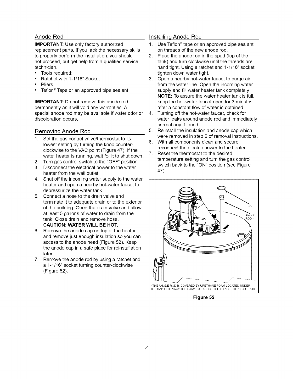
Anode Rod
IMPORTANT: Use only factory authorized
replacement parts. If you lack the necessary skills
to properly perform the installation, you should
not proceed, but get help from a qualified service
technician.
• Tools required:
• Ratchet with 1-1/16" Socket
• Pliers
• Teflon ®Tape or an approved pipe sealant
IMPORTANT: Do not remove this anode rod
permanently as it will void any warranties. A
special anode rod may be available if water odor or
discoloration occurs.
Removing Anode Rod
1. Set the gas control valve/thermostat to its
lowest setting by turning the knob counter-
clockwise to the VAC point (Figure 47). If the
water heater is running, wait for it to shut down.
2. Turn gas control switch to the "OFF" position.
3. Disconnect the electrical power to the water
heater from the wall outlet.
4. Shut off the incoming water supply to the water
heater and open a nearby hot-water faucet to
depressurize the water tank.
5. Connect a hose to the drain valve and
terminate it to adequate drain or to the exterior
of the building. Open the drain valve and allow
at least 5 gallons of water to drain from the
tank. Close drain and remove hose.
CAUTION: WATER WILL BE HOT.
6. Remove the anode cap on top of the heater
and remove just enough insulation so you can
access to the anode head (Figure 52). Keep
the anode cap in a safe place for reinstallation
later.
7. Remove the anode rod by using a ratchet and
a 1-1/16" socket turning counter-clockwise
(Figure 52).
Installing Anode Rod
1. Use Teflon®tape or an approved pipe sealant
on threads of the new anode rod.
2. Place the anode rod in the spud (top of the
tank) and turn clockwise until the threads are
hand tight. Using a ratchet and 1-1/16" socket
tighten down water tight.
3. Open a nearby hot-water faucet to purge air
from the water line. Open the incoming water
supply and fill water heater tank completely
NOTE: To assure the water heater tank is full,
keep the hot-water faucet open for 3 minutes
after a constant flow of water is obtained.
4. Turning off the hot-water faucet, check for
water leaks around anode rod and immediately
correct any if found.
5. Reinstall the insulation and anode cap which
were removed in step 6 of removal instructions.
6. With all components clean and secure,
reconnect the electric power to the heater.
7. Reset the thermostat to the desired
temperature setting and turn the gas control
switch back to the "ON" position (see Figure
47).
CAP
* THE ANODE ROD tS COVERED BY URETHANE FOAM LOCATED UNDER
THE CAR CHiP AWAY THE FOAM TO EXPOSE THE TOP OF THE ANODE ROD
Figure 52
51

Temperature-Pressure Relief Valve Test
j_ •Burn hazard.
_{__ • Hot water discharge.
• Keep clear of
1-__ _ temperature-pressure
relief valve discharge.
It is recommended that the temperature-pressure
relief valve be checked to ensure it is in operating
condition at least once a year.
When checking the temperature-pressure relief
valve operation, make sure that (1) no one is
in front of or around the outlet of the T&P valve
discharge line, and (2) that water discharge will
not cause any property damage, as water may be
extremely hot. Use care when operating valve as
the valve may be hot.
To check the relief valve, lift lever at the end of
valve several times (see Figure 53). The valve
should seat properly and operate freely.
If after manually operating the valve, it fails to
completely reset and continues to release water,
immediately close the cold-water inlet to the water
heater and drain the water heater, see "Draining
and Flushing" section. Replace the T&P valve with
a properly rated/sized new one.
TEMPERATURE-PRESSURE
DISCHARGE PIPE
Figure 53
If the temperature-pressure relief valve on the water
heater weeps or discharges periodically, it may be
due to thermal expansion.
T&P valve is not intended for the constant relief of
thermal expansion.
Temperature-pressure relief valve leakage due
to pressure build up in a closed system that does
not have a thermal expansion tank installed is
not covered under the limited warranty. Thermal
expansion tanks must be installed on all closed
water systems.
Explosion Hazard
• Temperature-pressure relief
valve must comply with ANSI
Z21.22-CSA4.4 and ASME
code.
• Properly sized temperature-
pressure relief valve must be
installed in opening provided.
• Do not plug, block, or cap the
discharge line.
• Failure to follow this warning
can result in excessive tank
pressure, serious injury or
death.
Draining And Flushing
Periodic draining and cleaning of sediment from
the tank may be necessary. It is recommended that
the tank be drained and flushed every 6 months
to remove sediment which may build up during
operation. The water heater should be drained if
being shut down during freezing temperatures.
See "Typical Installation" section in this manual for
location of the water heater components described
below.
rvlmT:l( (I
• Burn hazard.
• Hot water discharge.
• Keep hands clear of drain
valve discharge.
NOTE: Excessive water pressure is the most
common cause of temperature-pressure relief
valve leakage. Excessive water system pressure
is most often caused by "thermal expansion" in a
"closed system." See "Closed Water Systems" and
"Thermal Expansion" sections of this manual. The
52

To Drain The Water Heater Storage Tank
If the water heater is running, wait for it to shut
down before continuing.
1. Turn "OFF" the electrical supply to the water
heater.
2. Turn "OFF" the gas supply at the main gas
shut-off valve if the water heater is going to be
shut down for an extended period.
3. Open a nearby hot-water faucet until the water
is no longer hot.
4. Close the cold-water inlet valve.
5. Connect a hose to the drain valve and
terminate it to an adequate drain or external to
the building.
6. Open the water heater drain valve and allow all
the water to drain from the tank.
NOTE: If the water heater is going to be shut
down and drained for an extended period, the
drain valve should be left open.
7. Close the water heater drain valve when all
water in the storage tank has drained.
8. To refill the water heater, follow the
instructions in the "Filling the Water Heater"
section.
9. Turn "ON" the gas supply at the main gas shut-
off valve.
10. Follow the lighting instructions on the label or
see "Lighting Instruction" to restart the water
heater.
CAUTION: DO NOT TURN ON POWER TO THE
WATER HEATER UNLESS THE TANK IS FULL.
OPEN A HOT-WATER FAUCET AND ALLOW THE
WATER TO RUN UNTIL THE AIR IS PURGED
AND THE WATER FLOWS UNINTERRUPTED
FROM THE FAUCET.
IMPORTANT: When operating a cold tank,
condensation can occur and drip on the burner.
This should not be confused with a tank leak.
To Flush The Water Heater Storage Tank
If the water heater is running, wait for it to shut
down before continuing.
1. Turn "OFF" the electrical supply to the water
heater.
2. Open a nearby hot-water faucet until the water
is no longer hot. Once water is cool, close
faucet.
3. Connect a hose to the drain valve and
terminate it to an adequate drain or external to
the building.
4. Ensure the drain hose is secured before and
during the entire flushing procedure. Flushing is
performed with system water pressure applied
to the water heater.
5. Open the water heater drain valve to flush the
storage tank.
6. Flush the water heater storage tank to remove
sediment and allow the water to flow until it
runs clean.
7. Close the water heater drain valve when
flushing is completed.
8. Remove the drain hose.
9. Ensure the heater is full of water.
10. Turn "ON" electrical supply to place water
heater back in operation and follow the lighting
instructions.
Service
Before calling for repair service, please read the
"Troubleshooting Guide" in this manual.
If a condition persists or you are uncertain about
the operation of the water heater, let the Sears
Service Center check it out.
Contact Sears Service Center at:
1-800-4-MY-HOME ®(1-800-469-4663).
53
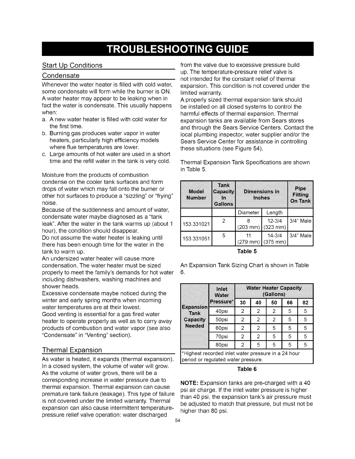
Start Up Conditions
Condensate
Whenever the water heater is filled with cold water,
some condensate will form while the burner is ON.
Awater heater may appear to be leaking when in
fact the water is condensate. This usually happens
when:
a. A new water heater is filled with cold water for
the first time.
b. Burning gas produces water vapor in water
heaters, particularly high efficiency models
where flue temperatures are lower.
c. Large amounts of hot water are used in a short
time and the refill water in the tank is very cold.
Moisture from the products of combustion
condense on the cooler tank surfaces and form
drops of water which may fall onto the burner or
other hot surfaces to produce a "sizzling" or "frying"
noise.
Because of the suddenness and amount of water,
condensate water maybe diagnosed as a "tank
leak". After the water in the tank warms up (about 1
hour), the condition should disappear.
Do not assume the water heater is leaking until
there has been enough time for the water in the
tank to warm up.
An undersized water heater will cause more
condensation. The water heater must be sized
properly to meet the family's demands for hot water
including dishwashers, washing machines and
shower heads.
Excessive condensate maybe noticed during the
winter and early spring months when incoming
water temperatures are at their lowest.
Good venting is essential for a gas fired water
heater to operate properly as well as to carry away
products of combustion and water vapor (see also
"Condensate" in "Venting" section).
Thermal Expansion
As water is heated, it expands (thermal expansion).
In a closed system, the volume of water will grow.
As the volume of water grows, there will be a
corresponding increase in water pressure due to
thermal expansion. Thermal expansion can cause
premature tank failure (leakage). This type of failure
is not covered under the limited warranty. Thermal
expansion can also cause intermittent temperature-
pressure relief valve operation: water discharged
from the valve due to excessive pressure build
up. The temperature-pressure relief valve is
not intended for the constant relief of thermal
expansion. This condition is not covered under the
limited warranty.
A properly sized thermal expansion tank should
be installed on all closed systems to control the
harmful effects of thermal expansion. Thermal
expansion tanks are available from Sears stores
and through the Sears Service Centers. Contact the
local plumbing inspector, water supplier and/or the
Sears Service Center for assistance in controlling
these situations (see Figure 54).
Thermal Expansion Tank Specifications are shown
in Table 5.
Diameter Length
2 8 12-3/4 314" Male
153.331021 (203 mm) (323 mm)
5 11 14-3/4 314" Male
153.331051 (279 mm) (375 mm)
Table 5
An Expansion Tank Sizing Chart is shown in Table
6.
" 30 40 so 66 82
E_i in.......
40ps 2 2 2 5 5
50psi 2 2 2 5 5
oupsl 2 2 5 5 5
70ps 2 2 5 5 5
80psi 2 5 5 5 5
*Highest recorded inlet water pressure in a 24 hour
or regulated water
Table 6
NOTE: Expansion tanks are pre-charged with a 40
psi air charge. If the inlet water pressure is higher
than 40 psi, the expansion tank's air pressure must
be adjusted to match that pressure, but must not be
higher than 80 psi.
54
WATER HEATER (3)
HnT Pn/rt J COLD WATER PRESSURE
._ _INLET FITTING REDUCING
r"'--_l_ _...f_-_-_, VALVE WITH
" I II BY-PASS
PRESSURE GAUGE INLET COLD
WATER SHUT-OFF
RECOMMENDED NSTALLAT ON
I I (VERTICAL MOUNTING)
WATER HEATER
COLD WATER
INLET FITTING FLOOR, CEILING JOIST, ETC.
HOT COLD
(3)
PRESSURE
REDUCING
VALVE WITH
(1) BY-PASS
EXPANSION /
TANK
PRESSURE GAUGE INLET COLD
WATER SHUT-OFF
ALTERNATE RECOMMENDED INSTALLATION
(HORIZONTAL MOUNTING)
Figure 54
Property Damage Hazard
Strange Sounds
Possible noises due to expansion and contraction
of some metal parts during periods of heat-up and
cool-down do not necessarily represent harmful or
dangerous conditions.
Condensation causes sizzling and popping
within the burner area during heating and cooling
periods and should be considered normal. See
"Condensate" section in this manual.
Operational Conditions
Smelly Water
Each water heater contains at least one anode
rod for corrosion protection of the tank. Certain
water conditions will cause a reaction between this
rod and the water. The most common complaint
associated with the anode rod is one of a "rotten
egg smell" in the hot water. The smell is a result of
four factors which must all be present for the odor
to develop:
a. A concentration of sulfate in the supply water.
b. Little or no dissolved oxygen in the water.
c. A sulfate reducing bacteria which has
accumulated within the water heater (this
harmless bacteria is nontoxic to humans).
d. An excess of active hydrogen in the tank. This is
caused by the corrosion protective action of the
anode.
• Avoid water heater damage.
• Install thermal expansion tank if necessary,
• Do not apply heat to cold water inlet.
• Contact qualified installer or service agency.
A properly-sized thermal expansion tank should
be installed on all closed systems to control the
harmful effects of thermal expansion. Contact a
plumbing service agency or your retail supplier
regarding the installation of a thermal expansion
tank.
Smoke/Odor
It is not uncommon to experience a small amount
of smoke and odor during the initial start-up. This
is due to burning off of oil from metal parts, and will
disappear in a short while.
Smelly water may be eliminated or reduced in some
water heater models by replacing the anode(s) with
one of less active material, and then chlorinating
the water heater tank and all water lines. Contact
Sears Service for further information concerning
this chlorination treatment and an anode
replacement kit #9001453. Anode replacement
and chlorination of the tank are not covered by
the water heater's limited warranty. If the smelly
water persists after the anode replacement and
chlorination treatment, we can only suggest that
chlorination or aeration of the water supply be
considered to eliminate the water problem.
NOTE: This anode rod may reduce but not
eliminate water odor problems. The water supply
system may require special filtration equipment
from a water conditioning company to successfully
eliminate all water odor problems.
Do not remove the anode leaving the tank
unprotected. By doing so, all warranty on the
water heater tank is voided.
55
"Air" In Hot-water Faucets
Explosion Hazard
• Flammable hydrogen gases may
be present.
• Keep all ignition sources away
from faucet when turning on hot
water.
HYDROGEN GAS: Hydrogen gas can be produced
in a hot-water system that has not been used
for a long period of time (generally two weeks or
more). Hydrogen gas is extremely flammable and
explosive. To prevent the possibility of injury under
these conditions, it is recommended that the hot-
water faucet, located farthest away, be opened for
several minutes before any electrical appliances
which are connected to the hot-water system are
used (such as a dishwasher or washing machine).
If hydrogen gas is present, there will probably be an
unusual sound similar to air escaping through the
pipe as the hot-water faucet is opened. There must
be no smoking or open flame near the faucet at the
time it is open.
56
Leakage Checkpoints
If a condition persists or you are uncertain about
the operation of the water heater contact a service
agency. Use this guide to check a "leaking" water
heater. Many suspected "leakers" are not leaking
tanks. Often the source of the water can be found
and corrected.
If you are not thoroughly familiar with gas codes,
your water heater and safety practices, contact your
gas supplier or qualified installer to check the water
heater.
Ensure the venting is properly attached and
secured.
Never use this water heater unless it is completely
filled with water. To prevent damage to the tank, the
tank must be filled with water. Water must flow from
the hot-water faucet before turning "ON" gas to the
water heater.
A. Water at the blower assembly is water vapor
which has condensed out of the combustion
products. This is caused by a problem in the
vent. A drainage port is included at the vent pipe
connection.
B. *Condensation may be seen on pipes in humid
weather or pipe connections may be leaking.
C. *The anode rod fitting may be leaking.
D. Small amounts of water from temperature-
pressure relief valve may be due to thermal
expansion or high water pressure in your area.
E. *The temperature-pressure relief valve may be
leaking at the tank fitting.
F. Water from a drain valve may be due to the
valve being slightly opened.
G. *The drain valve may be leaking at the tank
fitting.
H. Combustion products contain water vapor which
can condense on the cooler surfaces of the tank.
Droplets form and drip onto the burner. This is
common at the time of start-up after installation
and when incoming water is cold.
I. Water in the water heater bottom may be from
condensation, loose connections, or the relief
valve .DO NOT replace the water heater until
a full inspection of all possible water sources is
made and necessary corrective steps taken.
Leakage from other appliances, water lines, or
ground seepage should also be checked.
* To check where threaded portion enters tank,
insert cotton swab between jacket opening
and fitting. If cotton is wet, follow "Draining"
instructions in the "Service and Adjustment"
section and then remove fitting. Put pipe dope
or Teflon tape on the threads and replace. Then
follow "Filling the Water Heater" instructions in
the "Water System Piping" section.
Read and understand instruction
manual and safety messages
before installing, operating or
servicing thiswater heater.
Failure to follow instructions and
safety messages could result in
death or serious injury.
Instruction manual must remain with
water heater.
Figure 55
57
These guidelines should be utilized by a qualified service agent.
BURNER FLAME
TOO HIGH
FLAME BURNS
AT ORIFICE
INSUFFICIENT
HOT WATER
WATER IS TOO HOT
SLOW HOT WATER
RECOVERY
DRIP FROM
RELIEF VALVE
,
2.
3. Orifice too large
1. Low gas pressure
2. Defective gas control valve/
thermostat
1. Low gas pressure
2. Orifice too small
3. Thermostat set too low
4. Gas control error codes
5. Sediment or lime in tank
6. Water heater too small
7. Wrong piping connections
8. Leaking faucets
9. Wasted hot water
10.Long runs of exposed piping
11.Hot-water piping in outside wall
¸ ii!i!i!ii i
Air inlets blocked 1. Unblock inlet air openings
Insufficient secondary air 2. Provide ventilation to water heater
1. Thermostat is too high
2. Defective gas control valve/
thermostat
,
2.
3.
4.
5.
6.
7.
8.
9.
Insufficient air/flue blockage
Low gas pressure
Orifice too small
Thermostat set too low
Heater too small
Wrong piping connection
3. Replace with correct orifice
1. Check with gas utility company
2. Replace gas control valve/
thermostat
Wasted hot water 4.
Flue clogged
Air inlets blocked
1. Pressure build-up
2. Heater stacking
3. Closed water system 2.
4. Improperly seated valve 3.
4.
1. Check with gas utility company
2. Replace with correct orifice (see
rating plate)
3. Turn temperature knob to higher
setting
4. Refer to gas control error codes
5. Drain/flush-provide water treatment
if needed
6. Install adequate heater
7. Correct piping: dip tube must be in
cold inlet
8. Repair faucets
9. Advise customer
10.Insulate piping
11.Insulate piping
1. Turn temperature knob to lower
setting
2. Replace the gas control valve/
thermostat
1. Provide ventilation to water heater.
Check flue way, flue baffle and
burner
2. Check with gas utility company
3. Replace with correct orifice (see
rating plate)
Turn temperature knob to higher
setting
5. Install adequate heater
6. Correct piping-dip tube must be in
cold inlet
7. Advise customer
8. Clean flue, locate source and
correct
9. Unblock inlet air openings
1. Use a pressure-reducing valve and
relief valve
Lower the thermostat setting
See thermal expansion section
Check Relief valve for proper
operation (Do Not plug T&P valve)
58

GAS CONTROL
VALVE/
THERMOSTAT FAILS
TO SHUT OFF
SMELLY WATER
iiiiiiiiiiiiiiiiiiiiiiiiiiiiiiiiiiiiiiiiiiiiiiiiiiiiiiiiiiiiiiiiiiiiiiiiiiiiiiiiiiiiiiiiiiiiiiiiiii i! ! ! i ! i ! iji i !i i ! ii ii i i !i ! ! ! i !i i i iii i i i i i i i i i i i i i i i i i i i i i i i i i i i i i i i i i i i i i i i i i i i i i i i i i i i¸ ii!i!i!il
CONDENSATION
COMBUSTION
ODORS
,
,
2.
3.
SMOKING
AND CARBON
FORMATION
UNABLE TO LIGHT
THE BURNER
SIZZLING,
RUMBLING NOISE
,
2.
3.
4.
,
2.
3.
4.
5.
1. Air inlets blocked
2. Insufficient air
3. Low gas pressure
4. Orifice too large
,
6.
,
Defective gas control valve/
thermostat
Sulfides in water supply 1.
Bacteria in water supply 2.
Incompatible anode 3.
Filling the new water heater for the 1.
first time
Moisture from the products of
combustion 2.
Water dripping from blower
assembly 3.
Undersized water heater
4.
Air inlets blocked 1.
Insufficient air 2.
Flue clogged
Heater installed in a confined area 3.
House too tight 4.
5.
1.
2.
Flue clogged 3.
Defective gas control valve/ 4.
thermostat
Heater installed in a confined area 5.
1. Air in gas line
2. Pressure switch
3. Blocked exhaust
4. Wire connection
5. Defective gas control valve/
thermostat
1. Replace gas control valve/
thermostat
Chlorination procedure
Chlorination procedure
Replace with anode appropriate for
water conditions
Normal operation: the condensation
should disappear after heater
warms up
Normal operation: the condensation
should disappear in time
Install condensate hose to drain
port on the rubber coupling
Install adequate heater
Unblock inlet air openings
Provide fresh air ventilation to the
water heater
Clean, locate source and correct
Provide fresh air ventilation to the
water heater
Provide fresh air ventilation to the
water heater
Unblock inlet air openings
Provide ventilation to water heater.
Check flue way, flue baffle and
burner
Check with gas utility company
Replace with correct orifice (see
rating plate)
Clean, locate source and correct
6. Replace gas control valve/
thermostat
7. Provide fresh air ventilation
1. Purge the air from gas line
2. Check the pressure switch, make
sure the pressure switch hose is
not kinked
3. Check vent pipe for blockage
4. Check wire connections
5. Replace the gas control valve/
thermostat
1. Scale and sediment 1.
2. Condensation dripping on burner 2.
Drain/flush-provide water treatment
if needed
Refer to "Condensate" section
59

WATER LEAKAGE
BLOWER WILL
NOT START
BLOWER RUNS
CONTINUOUSLY
HOT SURFACE
IGNITER NOT
GLOWING
FOLLOWING WARM-
UP PERIOD
VENT PIPE TOO
HOT
iiiiiiiiiiiiiiiiiiiiiiiiiiiiiiiiiiiiiiiiiiiiiiiiiiiiiiiiiiiiiiiiiiiiiiiiiiiiiiiiiiiiiiiiiiiiiiiiiii i! ! ! i ! i ! iji i !i i ! ii ii i i !i ! ! ! i !i i i iii i i i i i i i i i i i i i i i i i i i i i i i i i i i i i i i i i i i i i i i i i i i i i i i i i i i¸ ii!i!i!il
1. Condensation 1. Refer to "Condensate" section
2. Dripping Temperature & Pressure 2. Refer to "Temperature & Pressure
,
4.
,
2.
3.
4.
5.
6.
,
,
,
4.
,
2.
3.
1.
2.
3.
4.
Relief Valve
Drain valve dripping/leaking 3.
Tank Leak
4.
No power to unit 1.
Thermostat set too low
Defective air pressure switch 2.
Defective blower
Disconnected or loose wire 3.
Control locked out 4.
5.
6.
Air pressure switch not closing due 1.
to insufficient draft - check for:
a. Vent piping blocked
b. Piping length too long
c. Clogged/dirty blower
Disconnected, torn or blocked
pressure switch hose from air
pressure switch to blower housing 2.
Defective pressure switch
High limit switch open due to 3.
excessive vent temperature or 4.
defective switch
120VAC polarity reversed at 1.
120VAC outlet receptacle
Defective hot surface igniter 2.
Defective gas control valve/ 3.
thermostat
Blower high limit switch fails to 1.
open - switch defective 2.
Not enough dilution air to mix with
flue gases
Air in room too hot for mixing with 3.
flue gases
Wrong burner orifice 4.
Relief Valve" section
Back flush to clean- out sediment,
replace if necessary.
Check "Leakage Checkpoints"
Plug in power cord, check fuses
and/or supply voltage
Turn temperature knob to higher
setting
Replace air pressure switch
Replace blower
Repair and reconnect wires
Refer to "Resetting The Heater
Control" - determine cause of
lockout
Determine cause of insufficient
draft. Check draft with manometer
at pressure switch
a. Remove blockage
b. Reduce vent length/increase
vent size
c. Clean blower wheel
Reconnect or replace pressure
switch hose
Replace defective pressure switch
Determine cause of overheating
check for: overfiring, insufficient
air supply, high ambient air
temperature
Reverse polarity at 120VAC outlet
receptacle
Replace igniter
Replace gas control valve/
thermostat
Replace blower high limit switch
Proper air circulation must be
provided for combustion and
dilution of flue temp
Increase ventilation to lower room
temperature
Install correct orifice.
6O
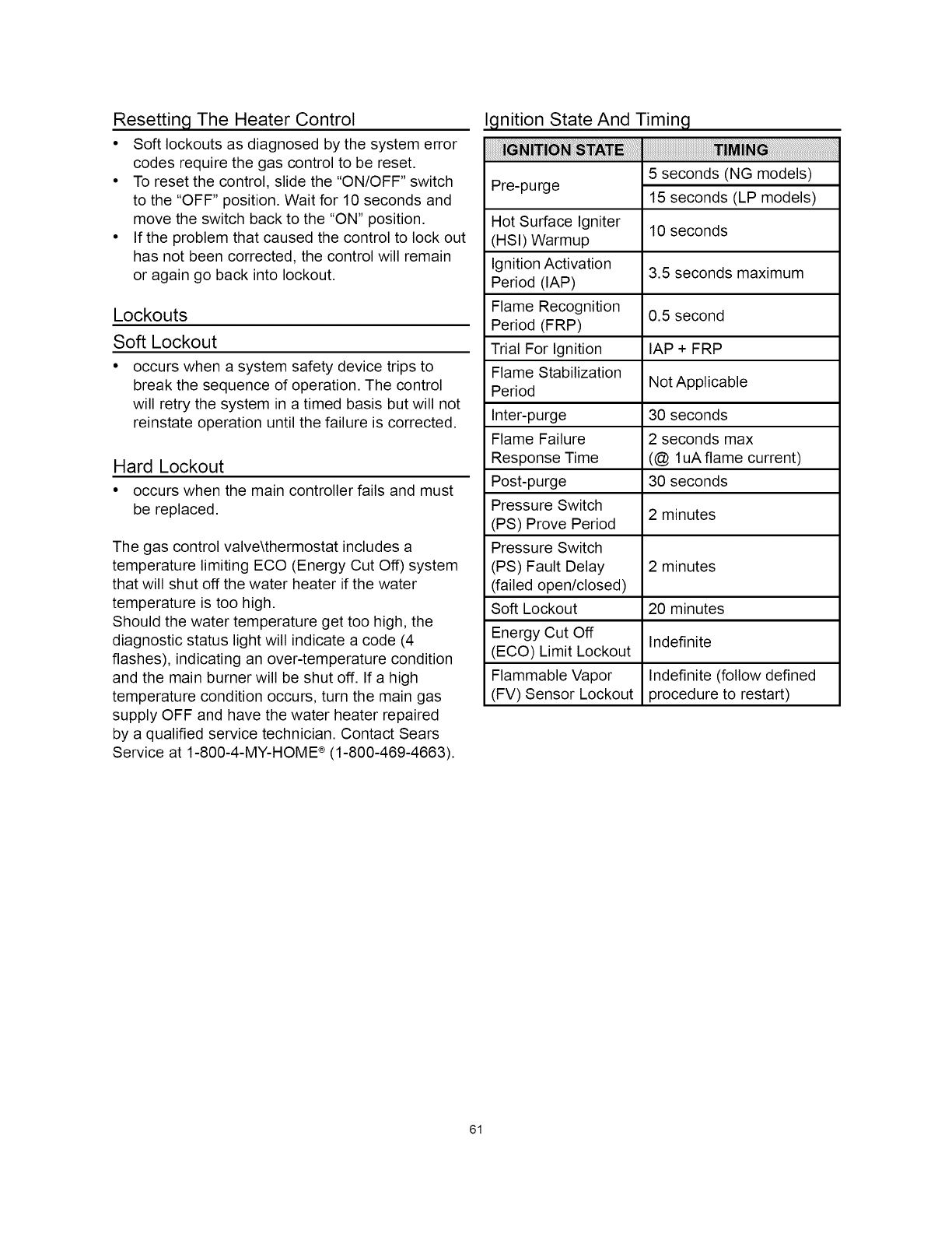
Resetting The Heater Control
• Soft lockouts as diagnosed by the system error
codes require the gas control to be reset.
• To reset the control, slide the "ON/OFF" switch
to the "OFF" position. Wait for 10 seconds and
move the switch back to the "ON" position.
• If the problem that caused the control to lock out
has not been corrected, the control will remain
or again go back into lockout.
Lockouts
Soft Lockout
occurs when a system safety device trips to
break the sequence of operation. The control
will retry the system in a timed basis but will not
reinstate operation until the failure is corrected.
Hard Lockout
• occurs when the main controller fails and must
be replaced.
The gas control valve\thermostat includes a
temperature limiting ECO (Energy Cut Off) system
that will shut off the water heater if the water
temperature is too high.
Should the water temperature get too high, the
diagnostic status light will indicate a code (4
flashes), indicating an over-temperature condition
and the main burner will be shut off. If a high
temperature condition occurs, turn the main gas
supply OFF and have the water heater repaired
by a qualified service technician. Contact Sears
Service at 1-800-4-MY-HOME ®(1-800-469-4663).
gnition State And Timing
irai : ....
Pre-purge 5 seconds (NG models)
15 seconds (LP models)
Hot Surface Igniter 10 seconds
(HSI) Warmup
Ignition Activation 3.5 seconds maximum
Period (lAP)
Flame Recognition 0.5 second
Period (FRP)
Trial For Ignition lAP + FRP
Flame Stabilization Not Applicable
Period
Inter-purge 30 seconds
Flame Failure 2 seconds max
Response Time (@ luA flame current)
Post-purge 30 seconds
Pressure Switch 2 minutes
(PS) Prove Period
Pressure Switch
(PS) Fault Delay 2 minutes
(failed open/closed)
Soft Lockout 20 minutes
Energy Cut Off Indefinite
(ECO) Limit Lockout
Flammable Vapor Indefinite (follow defined
(FV) Sensor Lockout procedure to restart)
61

System Status And Error Codes
The micro-controller inside the gas control monitors the flammable vapor safety features, the ignition
sequence, temperature settings and overall operation of the heater. If any of these parameters does not
operate properly the controller will shut down the water heater, diagnose the failure and flash an error
code. The following table lists the System Status Codes for the Honeywell control. Refer to it and to
the "Trouble Shooting Checklist" to diagnose the problem before attempting corrective action. See also
"Flammable Vapor Sensor".
IDLE (no call for heat, no fault conditions) 1Short flash once every four seconds
"Heartbeat", alternates bright/dim
One Flash, three second pause
Two Flash, three second pause
Three Flash, three second pause
Four Flash, three second pause
Five Flash, three second pause
Six-One Flash, three second pause
Six-Two Flash, three second pause
Six-Three Flash, three second pause
Six-Four Flash, three second pause
Seven Flash, three second pause
Eight-One Flash, three second pause
Eight-Two Flash, three second pause
Eight-Three Flash, three second pause
Eight-Four Flash, three second pause
LED continuously "ON"
Call For Heat (no fault conditions)
Low Flame Signal (control continues to operate)
Pressure Switch Failed Closed
Pressure Switch Failed Open
ECO (Energy Cut Off) Limit Lockout
thermostat temperature limit was exceeded.
Flame Out Of Sequence
Soft Lockout
- Retry Limit
- Failed Trial For Ignition
Soft Lockout
- Recycle Limit
- Pressure Switch/High Limit opened
Soft Lockout
- Recycle Limit
- Flame Lost
Soft Lockout
- Flame out of Sequence Sensed
Flammable Vapor Sensor (FVS) Lockout
Flammable Vapor Sensor (FVS) Fault Detected
Temperature Sensor Fault Detected
Electronics Fault Detected
Valve Fault Detected
Hard Lockout
2
3
4
5
10
11
12
13
14
15
16
17
Reading The LED Flash Sequence.
The LED indicator light is active when the gas valve/thermostat is in operation. The light will normally
show a status of 1 or 2 as listed in the "System Status And Error Code Chart". Multiple flash codes read
as follows:
Example. Item 9, six-two flash, three second pause. For this code, the LED indicator light will make six
bright flashes, pause for one second and then make two more bright flashes. The LED will pause for three
seconds and repeat the six-two cycle of flashes.
62
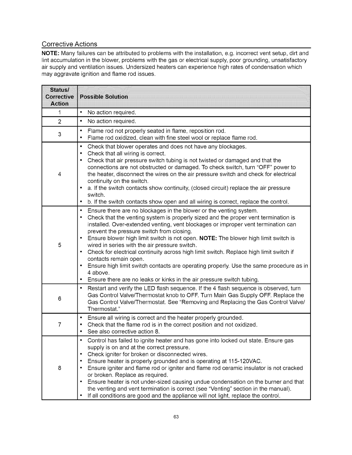
Corrective Actions
NOTE: Many failures can be attributed to problems with the installation, e.g. incorrect vent setup, dirt and
lint accumulation in the blower, problems with the gas or electrical supply, poor grounding, unsatisfactory
air supply and ventilation issues. Undersized heaters can experience high rates of condensation which
may aggravate ignition and flame rod issues.
1 • No action required.
2 • No action required.
3
4
5
6
7
8
• Flame rod not properly seated in flame, reposition rod.
• Flame rod oxidized, clean with fine steel wool or replace flame rod.
• Check that blower operates and does not have any blockages.
• Check that all wiring is correct.
• Check that air pressure switch tubing is not twisted or damaged and that the
connections are not obstructed or damaged. To check switch, turn "OFF" power to
the heater, disconnect the wires on the air pressure switch and check for electrical
continuity on the switch.
• a. If the switch contacts show continuity, (closed circuit) replace the air pressure
switch.
• b. If the switch contacts show open and all wiring is correct, replace the control.
• Ensure there are no blockages in the blower or the venting system.
• Check that the venting system is properly sized and the proper vent termination is
installed. Over-extended venting, vent blockages or improper vent termination can
prevent the pressure switch from closing.
• Ensure blower high limit switch is not open. NOTE: The blower high limit switch is
wired in series with the air pressure switch.
• Check for electrical continuity across high limit switch. Replace high limit switch if
contacts remain open.
• Ensure high limit switch contacts are operating properly. Use the same procedure as in
4 above.
• Ensure there are no leaks or kinks in the air pressure switch tubing.
• Restart and verify the LED flash sequence. If the 4 flash sequence is observed, turn
Gas Control Valve/Thermostat knob to OFF. Turn Main Gas Supply OFF. Replace the
Gas Control Valve/Thermostat. See "Removing and Replacing the Gas Control Valve/
Thermostat."
• Ensure all wiring is correct and the heater properly grounded.
• Check that the flame rod is in the correct position and not oxidized.
• See also corrective action 8.
• Control has failed to ignite heater and has gone into locked out state. Ensure gas
supply is on and at the correct pressure.
• Check igniter for broken or disconnected wires.
• Ensure heater is properly grounded and is operating at 115-120VAC.
• Ensure igniter and flame rod or igniter and flame rod ceramic insulator is not cracked
or broken. Replace as required.
• Ensure heater is not under-sized causing undue condensation on the burner and that
the venting and vent termination is correct (see "Venting" section in the manual).
• If all conditions are good and the appliance will not light, replace the control.
63
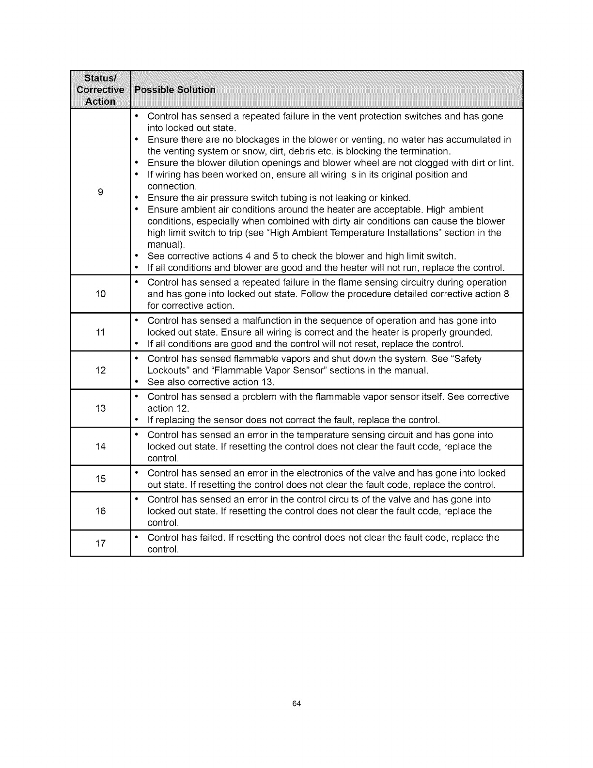
• Control has sensed a repeated failure in the vent protection switches and has gone
into locked out state.
• Ensure there are no blockages in the blower or venting, no water has accumulated in
the venting system or snow, dirt, debris etc. is blocking the termination.
• Ensure the blower dilution openings and blower wheel are not clogged with dirt or lint.
• If wiring has been worked on, ensure all wiring is in its original position and
connection.
9• Ensure the air pressure switch tubing is not leaking or kinked.
• Ensure ambient air conditions around the heater are acceptable. High ambient
conditions, especially when combined with dirty air conditions can cause the blower
high limit switch to trip (see "High Ambient Temperature Installations" section in the
manual).
• See corrective actions 4 and 5 to check the blower and high limit switch.
• If all conditions and blower are good and the heater will not run, replace the control.
• Control has sensed a repeated failure in the flame sensing circuitry during operation
10 and has gone into locked out state. Follow the procedure detailed corrective action 8
for corrective action.
• Control has sensed a malfunction in the sequence of operation and has gone into
11 locked out state. Ensure all wiring is correct and the heater is properly grounded.
• If all conditions are good and the control will not reset, replace the control.
• Control has sensed flammable vapors and shut down the system. See "Safety
12 Lockouts" and "Flammable Vapor Sensor" sections in the manual.
• See also corrective action 13.
• Control has sensed a problem with the flammable vapor sensor itself. See corrective
13 action 12.
• If replacing the sensor does not correct the fault, replace the control.
• Control has sensed an error in the temperature sensing circuit and has gone into
14 locked out state. If resetting the control does not clear the fault code, replace the
control.
• Control has sensed an error in the electronics of the valve and has gone into locked
15 out state. If resetting the control does not clear the fault code, replace the control.
• Control has sensed an error in the control circuits of the valve and has gone into
16 locked out state. If resetting the control does not clear the fault code, replace the
control.
• Control has failed. If resetting the control does not clear the fault code, replace the
17 control.
64

This page intentionally left blank.
May be used for notes or to record other installation information.
65
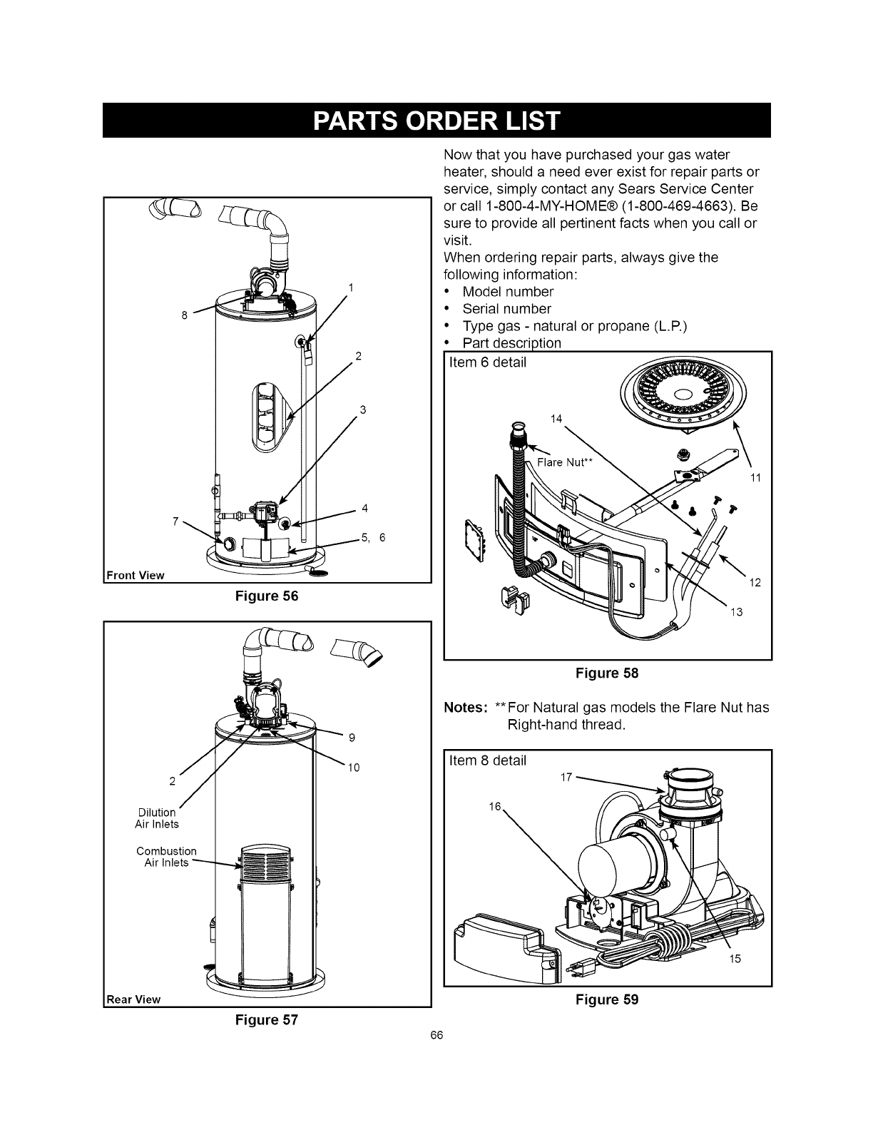
Front View _ D
Figure 56
1
/
3
/
Rear View
9
10
Dilution
Air Inlets
Combustion
Air Inlets "'---
Now that you have purchased your gas water
heater, should a need ever exist for repair parts or
service, simply contact any Sears Service Center
or call 1-800-4-MY-HOME® (1-800-469-4663). Be
sure to provide all pertinent facts when you call or
visit.
When ordering repair parts, always give the
following information:
• Model number
• Serial number
• Type gas - natural or propane (L.R)
Part description
Item 6 detail
14
12
Figure 58
Notes: **For Natural gas models the Flare Nut has
Right-hand thread.
Item 8 detail
16
Figure 59
15
Figure 57 66
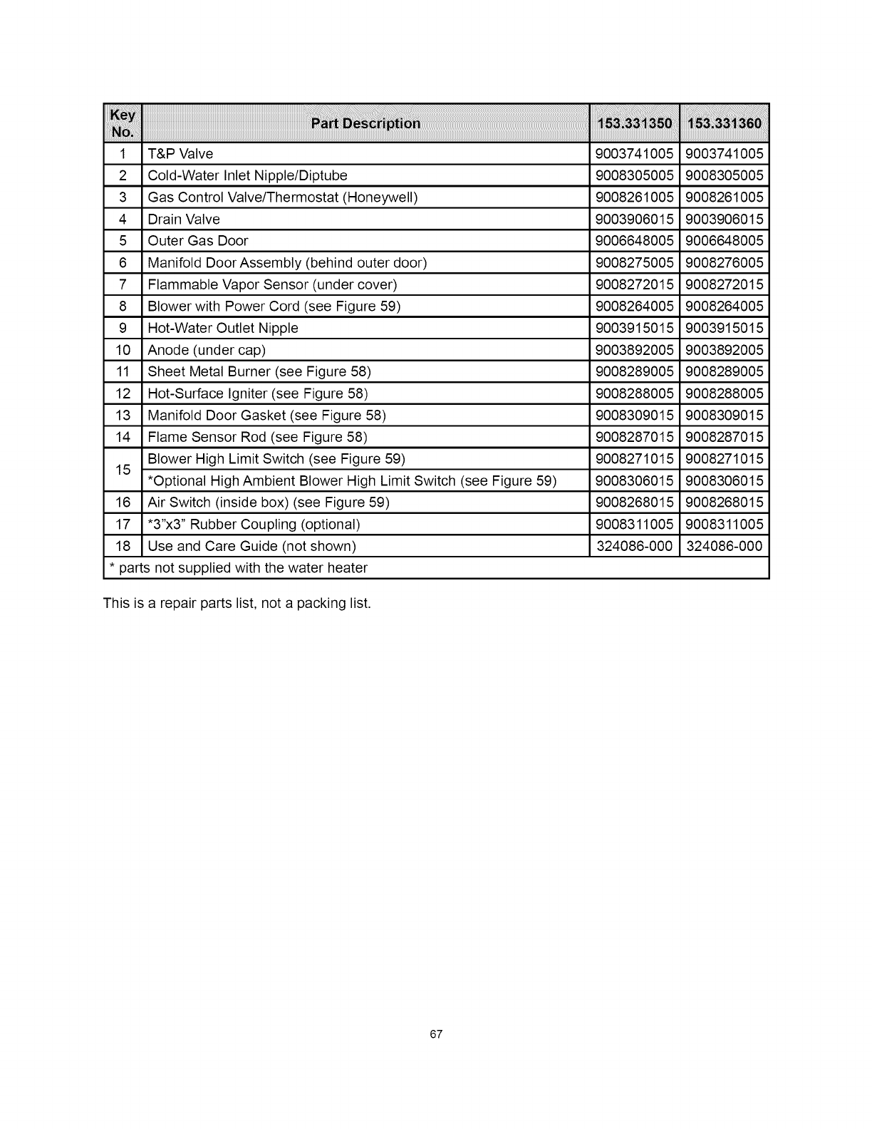
1 T&P Valve 9003741005 9003741005
2 Cold-Water Inlet Nipple/Diptube 9008305005 9008305005
3 Gas Control Valve/Thermostat (Honeywell) 9008261005 9008261005
4 Drain Valve 9003906015 9003906015
5 Outer Gas Door 9006648005 9006648005
6 Manifold Door Assembly (behind outer door) 9008275005 9008276005
7 Flammable Vapor Sensor (under cover) 9008272015 9008272015
8 Blower with Power Cord (see Figure 59) 9008264005 9008264005
9 Hot-Water Outlet Nipple 9003915015 9003915015
10 Anode (under cap) 9003892005 9003892005
11 Sheet Metal Burner (see Figure 58) 9008289005 9008289005
12 Hot-Surface Igniter (see Figure 58) 9008288005 9008288005
13 Manifold Door Gasket (see Figure 58) 9008309015 9008309015
14 Flame Sensor Rod (see Figure 58) 9008287015 9008287015
Blower High Limit Switch (see Figure 59) 9008271015 9008271015
15 *Optional High Ambient Blower High Limit Switch (see Figure 59) 9008306015 9008306015
16 Air Switch (inside box) (see Figure 59) 9008268015 9008268015
17 "3"x3" Rubber Coupling (optional) 9008311005 9008311005
18 Use and Care Guide (not shown) 324086-000 324086-000
* parts not supplied with the water heater
This is a repair parts list, not a packing list.
67
Your Home
For troubleshooting, product manuals and expert advice:
managemylife
www.managemylife.com
For repair - in your home - of all major brand appliances,
lawn and garden equipment, or heating and cooling systems,
no matter who made it, no matter who sold it!
For the replacement parts, accessories and
owner's manuals that you need to do-it-yourself.
For Sears professional installation of home appliances
and items like garage door openers and water heaters.
1-800-4-MY-HOME ®(1-800-469-4663)
Call anytime, day or night (U.S.A. and Canada)
www.sears.com www.sears.ca
Our Home
For repair of carry-in items like vacuums, lawn equipment,
and electronics, call anytime for the location of your nearest
Sears Parts & Repair Service Center
1-800-488-1222 (U.S.A.) 1-800-469-4663 (Canada)
www.sears.com www.sears.ca
To purchase a protection agreement on a product serviced by Sears:
1-800-827-6655 (U.S.A.) 1-800-361-6665 (Canada)
Para pedir servicio de reparaci6n
a domicilio, y para ordenar piezas:
1-888-SU-HOGAR ®
(1-888-784-6427)
www.sears.com
Au Canada pour service en frangais:
1-800-LE-FOYER Mc
(1-800-533-6937)
www.sears.ca
s@8rs
TM
® Registered Trademark /Trademark of KCD IP, LLC in the United States, or Sears Brands, LLC in other countries
® Marca Registrada !TMMarca de Fabrica de KCD IP, LLC en Estados Unidos, o Sears Brands, LLC in otros paises
MCMarque de commerce !MDMarque deposee de Sears Brands, LLC
