Kenmore 153334290 User Manual ENERGY EFFICIENT 5 GAS WATER HEATER Manuals And Guides L9080252
KENMORE Water heater, Gas Manual L9080252 KENMORE Water heater, Gas Owner's Manual, KENMORE Water heater, Gas installation guides
User Manual: Kenmore 153334290 153334290 KENMORE ENERGY EFFICIENT 5 GAS WATER HEATER - Manuals and Guides View the owners manual for your KENMORE ENERGY EFFICIENT 5 GAS WATER HEATER #153334290. Home:Plumbing Parts:Kenmore Parts:Kenmore ENERGY EFFICIENT 5 GAS WATER HEATER Manual
Open the PDF directly: View PDF ![]() .
.
Page Count: 26
Owners
Manual
FOR POTABLE WATER
HEATING ONLY
NOT SUITABLE FOR
SPACEHEATING
NOT FOR USE IIX[,
MOBILE HOMES
Hodel No.
153.334290 40 Gal. Short
153.334390 30 Gal.
IS3.334490 40 Gal.
153.334S90 S0 Gal.
Caution:
Read and Follow
All Safety Rules and
Operating Instructions
Before First Use of
This Product.
Savethis Manual for Future Reference.
•Safety Instructions
•Installation
• Operation
'IENERGY EFFICIENTT"5
GAS WATER HEATER
• Care and Maintenance
• Troubleshooting
• Parts List
For Your Safety
AN ODORANT IS ADDED TO THE GAS USED BY THIS
WATER HEATER
WARNING: If the information in these instructions are not fol-
lowed exactly, afire or explosion may result, causing property
damage, personal ,nlury or death•
-Do not store or use gas.oline or other flammable vapors and liq-
uids in the vicinity of this or any other appliance.
-WHAT TO DO IF YOU SMELL GAS
:Do not try to light any appliance.
Do not touch any electrical switch; do not use any phone in your
building.
iImmediately call your gas supplier from a neighbor's phone.
Follow the gas supplier'sinstructions.
If you can not reach your gas supplier, call the fire department.
-Installation and service must be performed by a qualified installer,
service agency or the gas supplier.
AWARNING I
• . . . .
Improper installation, adjustment, alteration, service or m_ntenance I
can cause DEATH, SERIOUS BODILY INJURY, OR PROPERTY DAM-
AGE. Refer to this manual for assistance or consult the local Sears
Serv ce Center or gas utility for further information.
AWARNING
Flammable vapors may be drawn by air currents from other areas
of the structure to this appliance.
AWARNING
READ THE GENERAL SAFETY SECTION BEGINNING ON INSIDE
COVER AND THEN THIS ENTIRE MANUAL BEFORE INSTALLING
OR OPERATING THIS WATER HEATER.
Sears, Roebuck and Co., Hoffman Estates, IL 60179 U.S.A.
Safety Precautions
AWARNING [
Improper installation, adjustment, alteration, service
or maintenance can cause DEATH, SERIOUS BODILY I
INJURY, OR PROPERTY DAMAGE. Refer to this mauu- I
al for assistance or consult your local Sears Service I
Center for further information. [
_,WARNING
WATER HEATERS EQUIPPED FOR ONE TYPE GAS
ONLY: This water heater is equipped for one type gas
only. Check the model rating plate near the gas control
valve for the correct gas. DO NOT USE THIS WATER
HEATER WITH ANY GAS OTHER THAN THE ONE
SHOWN ON THE MODEL RATING PLATE. Failure to
usethe correct gas can causeproblems which can result in
DEATH, SERIOUS BODILY INJURY, OR PROPERTY
DAMAGE. If you have any questions or doubts consult
your gassupplier or local utility.
_,WARNING
INSTALLATIONS IN AREAS WHERE FLAMMABLE LIQ-
UIDS (VAPORS) ARE LIKELY TO BE PRESENT OR
STORED (GARAGES, STORAGE, AND UTILITY AREAS
ETC): F ammable liquids (such as gasoline, solvents,
propane (LP) or butane, etc.), all of which emit flammable
vapors, may be improperly stored or used in such areas.
The gaswater heater pilot light or main bumer can ignite
such vapors. The resulting flashback and fire can cause
death or serious burns to anyone in the area, as well as
property damage.
If installation in such areas is your only option, then the
installation must be accomplished in a way that the pilot
flame and main burner flame are elevated from the floor
at least 18 inches. While this may reduce the chances of
flammable vapors from a floor spill being ignited, gasoline
and other flammable substancesshould never be stored or
used in the same room or area containing a gas water
heater or other open flame or spark producingappliance.
NOTE: Flammable vapors may be drawn by air current
from other areas of the structure to the appliance.
AWARNING
If this water heater will be used in beauty shops, barber
shops, cleaning establishments, or self-servica laundries
with dry cleaning equipment, it is imperative that the
water heater or water heaters be installed so that com-
bustion and ventilation air be taken from outside these
areas. Refer to the "Facts to Consider About the
Location" section of this manual and also the latest edi-
tion of the National Fuel Gas Code, ANSI Z223.1, also
referred to as NFPA 54 for specifics provided concerning
air required.
_,WARNING I
A fire can start if combustiblematerialssuchas clothingI
cleaningmaterials,or flammableliquidsare placedagainst
or nextto the water heater.
AWARNING
At the time of manufacture this water heater was provid-
ed with acombination temperature-pressures relief valve
certified by _nationally recognized testing laboratory
that maintains periodic inspection of production of listed
equipment ol"materials, as meeting the requirements for
Relief Valves and Automatic Gas Shutoff Devices for Hot
Water Supply Systems, and the atest edition of ANSI
Z21.22 end the code requirements of ASME. If replaced,
the valve must meet the requirements of local codes, hut
not less than a combination temperature and pressure
relief valve certified as meeting the requirements for
Relief Valves and Automatic Gas Shutoff Devices for Hot
Water Supply Systems, ANSI Z21.22 by a nationally rec-
ognized testing laboratory that maintains periodic
inspection of production of listed equipment or
materials.
The valve must be marked with a maximum set pressure
not to exceed the marked hydrostatic working pressure
of the water heater (150 Ibs./sq. in.) and a discharge
capacity not less than the water heater input rate as
shown on the model rating plate. (Electric heaters -
watts divided by 1000 x 3415 equal BTU/Hr. rate.)
Your local jurisdictional authority, while mandating the
use of a tempereture.pressure relief valve complying
with ANSI Z21.22 and ASME, may require a valve mode]
different from the one furnished with the water heater.
Compliance with such local requirements must be satis-
fied by the installer or end user oftbe water heater with
a locally prescribed temperature-pressure relief valve
installed in the designated opening in the water heater in
_lece of the factory fumished valve.
For safe operation of the water heater, the relief valve
must not be removed from it's designated opening or
plugged.
The temperature-pressure relief valve must be installed
directly into the fitting of the water heater designated for
the relief valve. Position the valve downward and provide
tubing so that any discharge will exit only within 6 inches
above, or at any distance below the structural floor. Be
certain that no contact is made with any live electrical
tort. The discharge opening must not be blocked or
reduced in size under any circumstances. Excessive
length, over 30 feet, or use of more than four elbows can
cause restriction and reduce the discharge capacity of
the valve.
No valve or other obstruction is to be placed between
the relief valve and the tank. Do not connect tubing
directly to discharge drain unlessa 6 air gap is provided.
To prevent bodily injury, hazard to life, or property dam-
age, the relief valve must be allowed to discharge water
in quantities should circumstances demand. If the dis-
charge pipe is not connected to adrain or other suitable
means, the water flow may cause property damage.
The Discharge Pipe:
• Must not be smaller in size than the outlet pipe size of
the valve, or have any reducing couplings or other
restrictions.
Must not be plugged or blocked.
Must be of material listed for hot water distribution.
Must be installed so as to allow complete drainage of
both the temperature-pressure relief valve, and the dis-
charge pipe.
Must terminate at an adequate drain.
Must not have any valve between the relief valve and
tan_
Safety Precautions
AWARNING
A gas water heater cannot operate properly without the
correct amount of air for combustion. Do not install in a
confined area such a closet, unless you provide air as
shown in the "Facts to Consider About the Location" sec-
tion. Never obstruct the flow of ventilation air. If you have
any doubts or questions at all, call your gas company.
Failure to provide the proper amount of combustion air
can result in a fire or explosion and can cause DEATH
SERIOUS BODILY INJURY,OR PROPERTY DAMAGE.
AWARNING
This water heater must not be installed directly on car-
peting. Carpeting must be protected by a metal or wood
panel beneath the appliance extending beyond the full
width and depth of the appliance by at least 3 inches
(76.2mm) in any direction, or if the appliance is installed
in an alcove or closet, the entire floor must be covered by
the panel. Failure to heed this warning may result in a
fire hazard.
AWARNING
HOTTER WATER CAN SCALD: Water heaters are
intended to produce hot water. Water heated to a tem-
perature which will satisfy clothes washing, dish washing,
and other sanitizing needs can scald and permanently
injure you upon contact. Some people are more likely to
be permanently injured by hot water than others. These
include the elderly, children, the infirm, or physically/men-
tally handicapped. If anyone using hot water in your home
fits into one of these groups or if there is a local code or
state law requiring a certain temperature water at the hot
water tap, then you must take specialprecautions. In addi-
tion to using the lowest possible temperature setting that
satisfiesyour hot water needs, a means such as a mixing
valve, should be used at the hot water taps used by these
people or at the water heater. Mixing valves are available
at plumbing supply or hardware stores. Follow manufac-
turers instructions for installation of the valves. Before
changing the factory setting on the thermostat, read the
"Temperature Regulation" section in this manual.
AWARNING
Soot build-up indicates aproblem that requires corroc-
tion before further use. Turn "OFF" gas to water heater
and leave "OFF" until repairs are made, because failure
to correct the cause of the sooting can result in a fire or
explosion causing DEATH, SERIOUS BODILY INJURY,
OR PROPERTY DAMAGE.
AWARNING
VENT DAMPERS -Any vent damper, whether it is operat-
ed thermally or otherwise must be removed if its use
inhibits proper drafting of the water heater.
Thermally Operated Vent Dampers: Gas-fired water
heaters having thermal efficiency in excess of 80% may
troduce arelatively low flue gas temperature. Such tem-
mraturas may nut be high enough to properly open ther-
mally operated vent dampers. This would cause spillageof
flue gasesand may cause carbon monoxide poisoning.
Vent dampers must bear evidence of certification as com-
plying with the latest edition of American National
Standard ANSI Z21.68 (ANSI Z21.66 & 67, respectively,
cover electrically and mechanically actuated vent
dampers). Before installation of any vent damper, consult
tour local Sears Service Center or the gas utility for fur-
ther information.
,_WARNING
•The appliance and its individual shutoff"valve must be dis-
connected from the gas supply piping system during any
pressure testing of the gas system at test pressures in
excessof ½ pound per square inch (3.SkPa).
•The appliance must be isolated from the gas supply pip-
ing system by closing its individual manual shutoff valve
during any pressure testing of the gas supply piping sys--
tom at test pressures equal or less than ½pound per
square inch (3.SkPa).
AWARNING
BEFORE LIGHTING [PROPANE (L.P.) GAS WATER
HEATERS]: Propane (L.R) gas is heavier than air. Should
there be a leak in the system, the gas will settle near the
ground. Basements, crawl spaces, skirted areas under
mobile homes (even when ventilated), closets and areas
below ground level will serve as pockets for the accumula-
tion of this gas. Before attempting to light or relight the
water heater's pilot or turning on a nearby electrical light
switch, be absolutely sure there is no accumulated gas in
the area. Search for odor of gas by sniffingat ground level
in the vicinity of the appliance. If odor is detected, follow
steps indicated at "For Your Safety" on the cover page of
this manual then leave the premises.
h, WARNING
Chemical vapor corrosion of the flue and vent system
may occur if air for combustion contains certain chemical
vapors. Spray can propellants, cleaning solvents, refrigera-
tor and air conditioner refrigerants, swimming pool
chemicals, calcium and sodium chloride, waxes, bleach,
and process chemicals are typical compounds which are
potentially corrosive.
AWARNING
Obstructed or deteriorated vent systems may present a
serious health Hsk or asphyxiat on.
Safety Precautions continued on page 4
3
Safety Precautions
AWARNING I
The water heater with draft hood installed must be prop. I
erly vented to a chimney which terminates outdoors.
Never operate the water heater unlessit is vented to the I
outdoors and has adequate air supply to avoid risks of
improper operation, explosion or asphyxiation.
_WARNING
Minimum clearances between the water heater and com-
bustible or non-combustible construction are I" at the
sidesand rear, 4" at the front, and 6" from the vent pipe.
Clearance from the top of the jacket is 18" on most mod-
els. Note that a lesser dimension may be allowed on some
models. Refer to the labe| on the water heater adjaceot to
the gascontrol valve for all clearances,
A CAUTION
WATER HEATERS EVENTUALLY LEAK: Installation of
the water heater must be accomplished in sucha manner
that if the tank or any connections should leak, the flow of
water will not cause damage to the structure. When such
locations cannot be avoided, a suitable drain pan should
be installed under the water heater. Drain pans are avail-
able at your local Sears store. Such adrain pan must be
not greater than 1% inches deep, have a minimum length
and width of at least 2 inches greater than the water
heater dimensions and must be piped to an adequate
drain. The pan must not restrict combustion air flow,
Under no circumstances is the manufacturer or Sears to
be held liable for any water damage in connection with
this water heater.
A WARNING
Do not use this appliance if any part of it has been under I
water. Immediately call a Sears Service Technician to I
_spect the applianceand to replace the gas control or any
_rt of the burner system which has been under water. I
_,WARNING
HYDROGEN GAS: Hydrogen gascanbe produced in a hot
water system that has not been used for a leng period of
time (generally two weeks or more). Hydrogen gas is
extremely flammable and explosive. To prevent the possi-
bility of injury under these conditions, we recommend the
hot water faucet be opened for several minutes at the
kitchen sink before any electrical appliances which are
connected to the hot water system are used (such as a dis-
hwather or washing machine). If hydrogen gas is present,
there will probably be an unusual sound similar to air
escaping through the pipe as the hot water faucet is
opened. There must be no smoking or open flame near
the faucet at the time it is open.
AWARNING
INSULATING JACKETS: When installing an external
water heater insulation jacket on agas water heater:
• DO NOT cover the temperature-pressure relief valve.
•DO Nor put insulation over any part of the top of the
gaswater heater.
•DO NOT put insulation over the gas control valve or gas
control valvelbumer cover, or any access areas to the
burner.
• DO NOT let insulation around the gas water heater to
get within 8 inches of the floor (air must get to the
burner).
• DO NOT cover or remove operating instructions, and
safety related warning labels and materials affixed to the
water heater.
Failure to heed this will result in the possibility of afire or
explosion.
Table of Contents
Safety Precautions ............................................................................................................................................2-4
Table of Contents ................................................................................................................................................_
Customer Responsibilities .......................................................................................................................6
Product Specifications ..................................................................................................................................6
Materials and Basic Tools Needed ...............................................................................................7
Materials Needed ...................................................................................................................................................................... 7
B_sic Tools ................................................................................................................................................................................ 7
Installation Instructions ........................................................................................................................8-16
Removing the Old Water Heater ............................................................................................................................................... 8
Facts to Consider About the Location ....................................................................................................................................... 9
Combustion Air and Ventilation for Appliances in Unconfined Spaces ................................................................................... 10
Combustion Air and Ventilation for Appliances in Confined Spaces ....................................................................................... 10
Water Piping ........................................................................................................................................................................... 11
Temperature-Pressure Relief Valve........................................................................................................................................... 12
Filling the Water Heater .......................................................................................................................................................... 13
Venting .............................................................................................................................................................................. 13-14
Gas Piping ......................................................................................................................................................................... 14-15
Installation Checklist .............................................................................................................................................................. t6
O eratin Instructions 17-19
_ig_ting ......... .g., ......................................................................................................................... 1718
Temperature Regulation .......................................................................................................................................................... 19
Service and Adjustment ......................................................................................................................20-21
Tank (Sediment) Cleaning ...................................................................................................................................................... 20
Venting System Inspection ...................................................................................................................................................... 20
Burner Inspection ................................................................................................................................................................... 20
Burner Cleaning ..................................................................................................................................................................... 20
Draining ................................................................................................................................................................................. 21
Temperature-Pressure Relief Valve Operation .......................................................................................................................... 21
Drain Valve Washer Replacement ........................................................................................................................................... 21
Housekeeping ......................................................................................................................................................................... 21
Service .................................................................................................................................................................................... 21
Troubleshooting Guide ........................................................................................................................22-22
Start Up Conditions .......................................................................................................................................................... 22-23
Condensation ....................................................................................................................................................................... 22
Smoke/Odor ......................................................................................................................................................................... 22
Thermal Expansion ......................................................................................................................................................... 22-23
Strange Sounds ..................................................................................................................................................................... 23
Operational Conditions ..................................................................................................................................................... 23-24
Smelly Water ......................................................................................................................................................................... 23
Air in Hot Water Faucets ...................................................................................................................................................... 23
High Temperature Shut Off System ...................................................................................................................................... 24
Not Enough Hot Water ........................................................................................................................................................ 24
Water is Too Hot .................................................................................................................................................................. 24
Leakage Checkpoints .............................................................................................................................................................. 25
Parts ---OrderList ...............................................................................................................................................26-27
Customer Responsibilities
Thank You for purchasinga Sears water heater.
Properly installed and maintained, it should give you years of
trouble free service. If you should decide that you want the new
water heater professionally installed by Sears call the local Sears
Service Center or any Sears store. They will arrange for prompt,
quality installation by Sears authorized contractors.
Abbreviations Found In This Instruction Manual
I.A.S. - International Approval Services, A Division of CSA
A.N.S.I. - American National Standards Institute
AWARNING
This gas-fired water heater is design certified by the
International Approval Services, A Division of CSA under
American National Standard/CSA Standard for GasWater
Heaters ANS Z21.10.1 • CSA 4.1 (latest edition). The
installation must conform with this manual, Local Codes
and with the latest edition of the National Fuel Gas Code,
ANSI Z223.1.
This publication is available from your local government or
public library, gas company, or by writing NFPA,
Batterymarch Park, Quincy, MA 02269.
•Read the "Safety Precautions" section, pages 2 through 4 of
this manual first and then the entire manual carefially. If you
don't follow the safety rules, the water heater will not operate
properly. It could cause DEATH, SERIOUS BODILY
INJURY AND/OR PROPERTY DAMAGE.
This manual contains instructions for the installation opera-
tion, and maintenance of the gas-fired water heater. It also
contains warnings through out the manual that you must read
and be aware of. All warnings and all instructions are essential
to the proper operation of the water heater and your safety.
Since we cannot put everythingon the first few page.s, READ
THE ENTIRE MANUAL BEFORE ATTEMPTING TO
INSTALL OR OPERATE THE WATER HEATER.
•The installation must conform with the instructions in this
manual; gas company rules; and Local Codes, or in the
absence of Local Codes, with the latest edition of the National
Fuel Gas code, ANSI Z223.1, also referred to as NFPA 54.
This publication is available from your local government or
public library or gas company or by writing NFPA,
Batterymarch Park, Quincy, MA 02269.
•If after reading this manualyou have any questions or do not
understand any portion of the instructions, call the Sears
Service Center.
•Carefully plan the place where you are going to put the water
heater. Correct combustion, vent action, and vent pipe instal-
lation are very important in preventing death from _ossible
carbon monoxide poisoning and fires. -
Examine the location to ensure the water heater complies with
the _Facts to Consider About the Location" section in this
manual.
•For California installation this water heater must be braced,
anchored, or strapped to avoid falling or moving during an
earthquake. See instructions for correct installation proce-
dures. Instructions may be obtained from your local dealer,
wholesaler, public utilities or California Office of the State
Architect, 400 P Street, Sacramento, CA 95814.
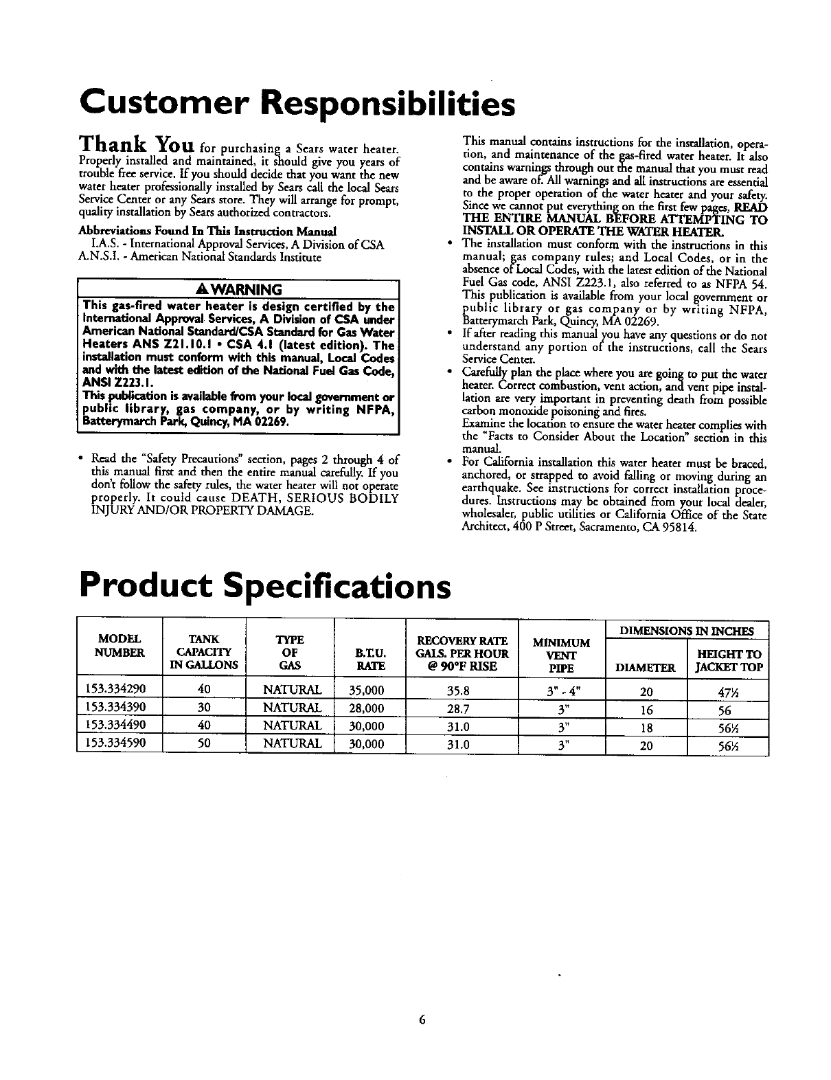
Product Specifications
MODEL
NUMBER
153.334290
153.334390
153.334490
153.334590
TANK TYPE RECOVERyRATE MINIMUM DIMENSIONS IN INCHES
CAPACITY
IN GALLONS
40
30
40
50
OF
GAS
NATURAL
NATURAL
NATURAL
NATURAL
B.T.U.
RATE
35,000
28,000
30,000
30,000
GALS.PERHOUR
@ 90°F RISE
35.8
28.7
31.0
31.0
VENT
PIPE
3"-4"
3"
3"
3"
DIAMETER
20
16
18
20
HEIGHT TO
JACKETTOP
475
56
56_
56½
6
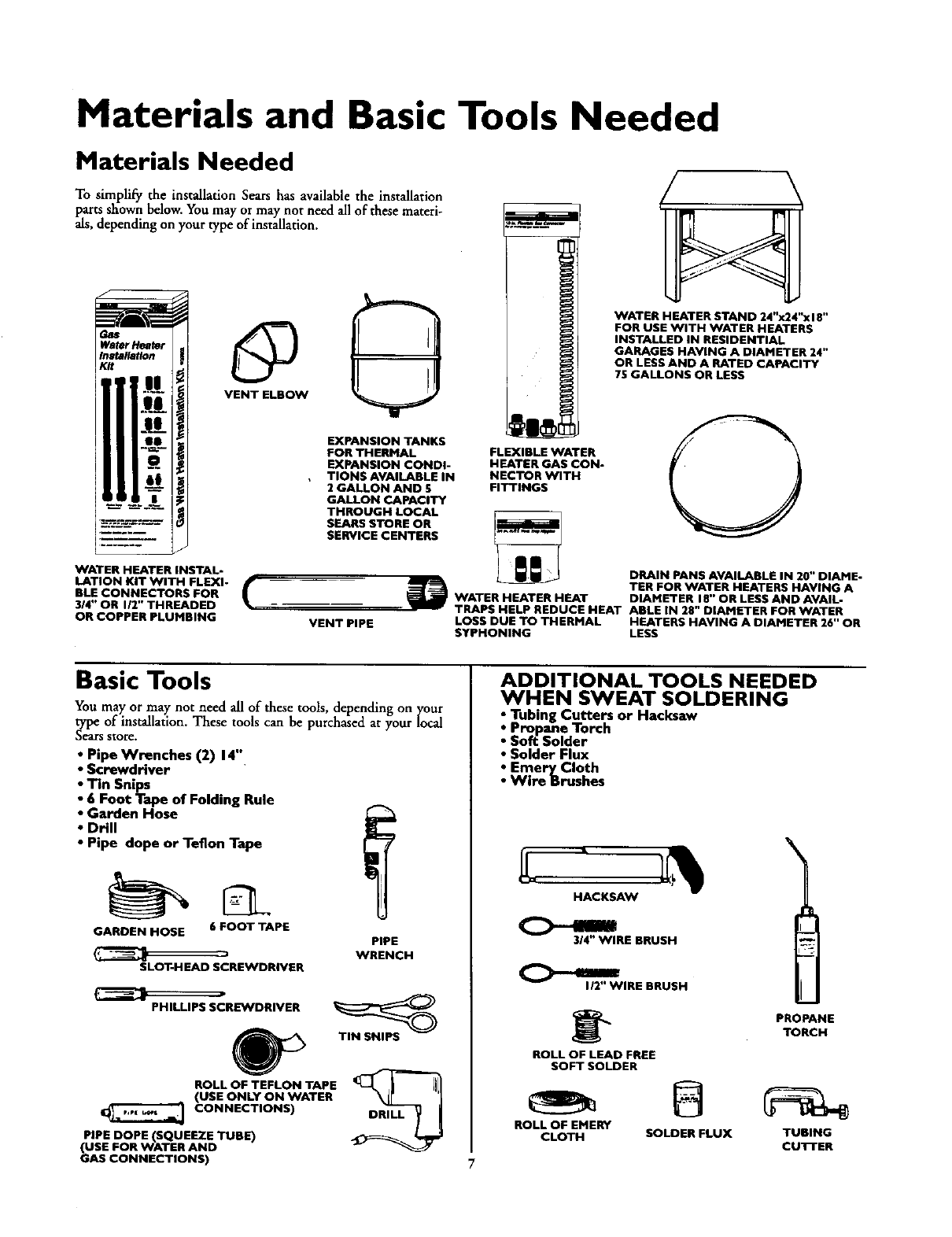
Materials and Basic Tools Needed
Materials Needed
To simplify the installation Sears has available the installation
parrs shown below. You may or may not need all of these materi-
als, depending on your type of installation.
WATER HEATER INSTAL-
LATION KIT WITH FLEXI-
BLE CONNECTORS FOR
314" OR liT' THREADED
OR COPPER PLUMBING
VENT ELBOW
EXPANSION TANKS
FOR THERMAL
EXPANSION CONDI-
TIONS AVAILABLE IN
2 GALLON AND 5
GALLON CAPACITY
THROUGH LOCAL
SEARS STORE OR
SERVICE CENTERS
VENT PiPE
I
FLEXIBLE WATER
HEATER GAS CON-
NECTORWITH
FITTINGS
WATER HEATER STAND 24"x24"x18"
FOR USE WITH WATER HEATERS
INSTALLED IN RESIDENTIAL
GARAGES HAVING A DIAMETER 24"
OR LESS AND A RATED CAPACITY
75 GALLONS OR LESS
DRAIN PANS AVAILABLE IN 20" DIAME-
TER FOR WATER HEATERS HAVING A
WATER HEATER HEAT DIAMETER 18" OR LESS AND AVAIL-
TRAPS HELP REDUCE HEAT ABLE IN 28" DIAMETER FOR WATER
LOSS DUE TO THERMAL HEATERS HAVING A DIAMETER 26" OR
SYPHONING LESS
Basic Tools
You may or may not need all of these tools, depending on your
type of installation. These tools can be purchased at your local
Sears store.
• Pipe Wrenches (2) 14"
•Screwdriver
• Tin Snips
•6Foot Tape of Folding Rule
•Garden Hose
•Drill
•Pipe dope or Teflon Tape
GARDEN HOSE 6 FOOT TAPE
SLOT-HEAD SCREWDRIVER
PIPE
WRENCH
PHILLIPS SCRE_NDRIVER
TIN SNIPS
ROLL OF TEFLON TAPE _L_J_ | [Jl
(USE ONLY ON WATER
CONNECTIONS) DRILL
PIPE DOPE (SQUEEZE TUBE)
(USE FOR WATER AND
GAS CONNECTIONS)
ADDITIONAL TOOLS NEEDED
WHEN SWEAT SOLDERING
•Tubing Cutters or Hacksaw
• Propane Torch
•Sof_ Solder
•Solder Flux
•Emery Cloth
•Wire Brushes
HACKSAW
314" WIRE BRUSH
112" WIRE BRUSH
ROLL OF LEAD FREE
SOFT SOLDER
ROLL OF EMERY
CLOTH SOLDER FLUX
\
PROPANE
TORCH
TUBING
CUTTER
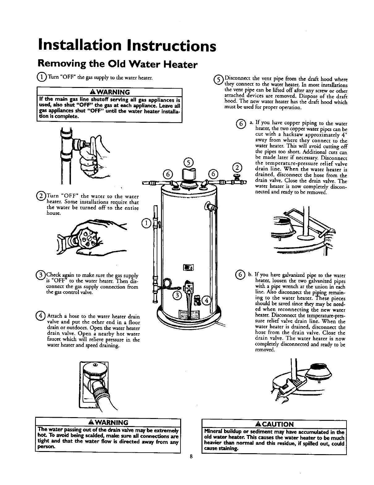
Installation Instructions
Removing the Old Water Heater
Turn "OFF" the supply the heater.
gas to water
AWARNING ]
I If the main gas line shutoff serving all gas appliances is/
used, also shut "OFF" the gas at each appliance. Lea_e alJ|
[ gas appliances shut "OFF" until the water heater installa-|
Ilion is complete. |
QTurn "OFF" the water to the water
heater. Some installations require that
the water be turned off to the entire
house,
Check a_mn to make sure the gas supply
is _OFF to the vcater heater. Then dis-
connect the gas supply connection from
the gas control valve.
Attach a hose to the water heater drain
valve and put the other end in a floor
drain or outdoors. Open the water heater
drain valve. Open anearby hot water
faucet which will relieve pressure in the
water heater and speed draining.
Disconnect the vent pipe from the draft hood where
they connect to the water heater. In most installations
the vent pipe canhe Liftedoff after any screw or other
attached devices are removed. Dispose of the draft
hood. The new water heater has the draft hood which
must be used for proper operation.
®
® ®
® ®
b.
a. If you have copper piping to the water
heater, the two copper water pipes can be
cut with ahacksaw approximately 4"
away from where they connect to the
water heater. This will avoid cutting off
the pipes too short. Additional cuts can
be made later if necessary. Disconnect
the temperature-pressure relief valve
drain line. When the water heater is
drained, disconnect the hose from the
drain valve. Close the drain valve. The
water heater is now completely discon-
nected and ready to be removed.
If you have galvanized pipe to the water
heater, loosen the twogalvanized pipes
with apipe wrench at the union in each
line. Also disconnect the piping remain-
ing to the water heater. These pieces
should be saved since they may be need-
ed when reconnecting the new water
heater. Disconnect the temperature-pres-
sure relief valve drain line. When the
water heater is drained, disconnect the
hose from the drain valve. Close the
drain valve. The water heater is now
completely disconnected and ready to be
removed.
AWARNING
The water passingout of the drain valve may be extremely
hot. To avoid being scalded,make sure all connectionsare
tight and that the water flow is directed away from any
pelTton.
ACAUTION ]
I Mineral buildup or sediment may have accumulated in the|
[ old water heater. This causesthe water heater to be much|
[ heavier than normal and this residue, if spilled out, could}
Icause staining. ]
Installation Instructions (cont'd)
Facts to Consider About the
Location
You should carefully choose an indoor location for the new
water heater, because the placement is avery important consid-
eration for the safety of the occupants in the building and for
the most economical use of the appliance. This water heater is
not for use in mobile homes or outdoor installation.
Whether replacing an old water heater or putting the water
heater in a new location, the following critical points must be
observed.
•The location selected should be indoors as close as practical
to the gas vent or chimney to which the water heater vent is
going to be connected, and as centralized with the water pip-
in._ system as possible. The water heater, as all water heaters,
will eventually leak. Do not install without adequate
drainage provisions where water flow will cause damage.
& CAUTION
WATER HEATERS EVENTUALLY LEAK: Installation of the
water heater must be accomplishedin such a manner that if
the tank or anyconnectionsshouldleak, tee flow of water will
not causedamageto the structure.When suchlocationscan-
not be avoided,a suitable drain pan shouldbe installedunder
the water heater. Drain pansare awllable at your localSears
store. Such a drain pan must be not greater than 1½inches
deep, have a minimum lengthand width of at least 2 inches
greater than the water heater dimensionsand must be piped
to anadequatedrairLThe panmust not restrictcombustionair
flow.Under no circumstancesis the manufactureror Searsto
be held liable for any water damage in connectionwith this
water heater.
AWARNING
INSTALLATIONS IN AREAS WHERE FLAMMABLE UQUIDS
(VAPORS) ARE LIKELY TO RE PRESENT OR STORED
(GARAGES, STORAGE, AND UTILITY AREAS, ETC):
Flammal_e liquids(suchasgasoline,solvents,propane(LP) or
butane, etc.), all of which emit flammable vapors, may be
imp_perly stored or usedin suchaxea_The gaswater heater
pilot lightor main burner canignitesuchvape_ The resulti.rig
flashbeckandfire can cansedezth er seriousbems te anyoeem
the area,aswellasprepertydamage.
If installationin suchareasis youronly option,thee the installa-
tion must be accomplishedin a way that the pilot flame anl
mainburner flameareelevatedfromthe floorat least 18inche_
While this mayreducethe chancesof flammablevaporsfrom a
floorspillbeing ignited,gasolineand other flammablesubstances
shouldneverbe stored or usedin the same roomor area con-
teining a gaswater heateror other opengameor sparkproduc.
ingappliance.
NOTE: Flammablevaporsmay be drawn by air cun_lts from
otherareasof thestructureto the appliance.
_,WARNING
Propellantsof aerosolspraysand volatile compounds,(clean-
ers,chlorinebasedchemicals,refrigerants,etc.) in additionto
being highlyflammable in manycases,will also changeto cor-
rosive hydrochloric acid when exposed to the combustion
productsof the water heater. The results can be hazardous
and alsocauseproduct failure.
•The location selection must provide adequate dearances for ser-
vicing and proper operation of the waterheater.
_,WARNING
This water heater must nut be instelladdirectly on carpe_ng,
Carpeting must be protected by ametal or wood panel
beneath the appliance extending beyondthe full width and
depth of the appliance by at least 3 inches (76.2mm) in any
direction,or if the applianceis installedin an alcoveor closet,
the entire floormust be coveredby the panel. Failureto heed
this warningmayresultina Erehazard.
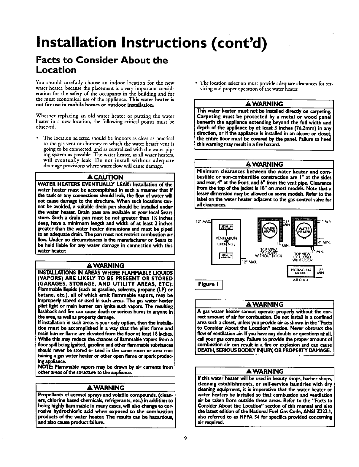
AWARNING
Minimum clearances between the water heater and com-
bustilde or non-combustibleconstructionare I" at the sides
and rear, 4" at the front, and 6" from the vent pipe. Clearance
from the top of the jacket is 18"on most medelL Note that a
lesserdimensionmay beallowed onsomemodal_ Referto the
label onthe water heater adjacentto the gas controlvalvefor
all clearance_
12" MAX._
VENTI T_ON
OPE_GS
Figure I I
TOP VI
OFCO T
WITHO_T)_R
AJRDUCT
A,WARNING
A gaswater heater cannot operate properlywithout the cor-
rect amount of air for combustion,Do not installina confined
area sucha doset, unlessyouprovideair asshown inthe "Facts
to ConsiderAbout the Location" section.Never obstructthe
flowof vantilationair. Ifyou haveanydoubtsor qeesdonsat all,
callyour gascompany.Failureto providethe properamount of
combustionair can result in afire or explosionand can cause
DEATH,SERIOUS BODILYINJURn,OR PROPERTYDAMAGE,
_,WARNING
If this water heater will be used in beautyshops,barber shops,
cleaning establishments, or self-service laundries with dry
cleaningequipment, it is imperative that the water heater or
water heatersbe installedso that combustionand ventilation
air be taken from outsidethese are_ Refer to the "Facts to
ConsiderAbout the Ler.adon"sectionof this manualand also
the latesteditionof the National FuelGas Code,ANSI Z223.1,
also referred to asNFPA 54 for specificsprovidedconcerning
air required.
9
Installation Instructions (cont'd)
Combustion Air and Ventilation
for Appliances Located in
Unconfined Spaces
Unconfined Space is a space whose volume is not less than 50
cubic feet per 1,000 Btu per hour of the aggregate input rating
of all appliances installed in that space. Rooms communicating
directly with the space in which the appliances are installed,
through openings not furnished with doors, are considered a
part of the unconfined space.
In unconfined spaces in buildings, infiltration may be adequate
to provide air for combustion, ventilation and dilution of"flue
gases. However, in buildings of tight construction (for example,
weather stripping, heavily insulated, caulked, vapor barrier,etc.),
additional air may need to be provided using the methods
described in Combustion Air and Ventilation for Appliances
Located in Confined Spaces, b.
Combustion Air and Ventilation
for Appliances Located in
Confined Spaces ,
Contined Space is aspace whose volume is less than 50 cubic
feet per 1,000 Btu per hour of the aggregate input rating of all
appliances installed in that space.
a_ALL AIR FROM INSIDE BUILDINGS:
(See Page 9 Figure 1, and Figure 2 below)
The confined space shall be provided with two permanent
openings communicating directly with an additional room(s)
of sufficient volume so that the combined volume of all
spaces meets the criteria for an unconfined space. The total
input of all gas utilization equipment installed in the com-
bined space shall be considered in making this determination.
Each opening shall have aminimum flee area of one square
inch per 1,000 BTU per hour of the total input rating of all
gas utilization equipment in the confined space, but not less
th,an 100 square inches. One opening shall commence within
12 of the top and one commencing within 12 of the bot-
tom of the enclosure.
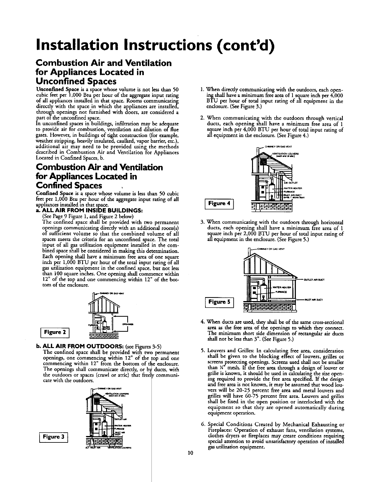
1.When directly communicating with the outdoors, each open-
ing shall havea minimum freearea of I square inch per 4,000
BTU per hour of total input rating of all equipment in the
enclosure. (SeeFigure 3.)
2. When communicating with the outdoors through vertical
ducts, each opening shall have a minimum free area of 1
square inch per 4,000 BTU per hour of total input rating of
all equipment in the enclosure. (SeeFigure 4.)
Figure 4 ]
3. When communicating with the outdoors through horizontal
ducts, each opening shall have a minimum free area of 1
_[_uareinch per 2,000 BTU per hour of total input rating of
equipment in the enclosure. (See Figure 5.)
Figure 2 ]
b, ALL AIR FROM OUTDOORS: (see Figures3-5)
The confined space shall be provided with two permanent
openings, one commencing within 12" of the :op and one
commencing within 12" from the bottom of t!_eenclosure.
The openingsshall communicate directly,or b, ducts,with
the outdoors or spaces (crawl or attic) that free communi-
carewith the outdoors.
Figure 3 I
Figure 5 ]
10
4. When ducts are used, they shall be of the same cross-sectional
area as the flee area of the openings to which they connect.
The minimum short side dimension of rectangular air ducts
shall not be less than 3". (See Figure 5.)
5. Louvers and Grilles: In calculating free area, consideration
shall be given to the blocking effect of louvers, grilles or
screens protecting openings. Screens used shall not be smaller
than ¼-mesh. If the free area through adesign of louver or
grille is known, it should be used in calculating the size open-
ing required to provide the free area specified. If the design
and free area is not known, it may be assumed that wood lou-
vers will be 20-25 percent free area and metal louvers and
grilles will have 60-75 percent free area. Louvers and grilles
shall be f'Lxedin the open position or interlocked with the
equ!pment so that they are opened automatically during
equipment operation,
6. Special Conditions Created by Mechanical Exhausting or
Fireplaces: Operation of exhaust fans, ventilation systems,
clothes dryersor fireplaces may create conditions requiring
specialattention to avoid unsatisfactoryoperationof installed
gasutilization equipment.
Installation Instructions (cont'd)
Water Piping
AWARNING
HOTTER WATER CAN SCALD:.Water heatersare intendedto
producehot water. Water heated to a temperature which will
satisfyclotheswashing,dishwashing,and other sanitizingneeds
canscaldand permanently injureyouupon con__.ct.Some peo-
pie are mote likelyto be permanentlyinjuredbyhot water than
othor_Theseincludethe elderly,children,the infirm,or physicad-
ly/meotallyhandicapped.Ifanyoneusinghot water in yourhome
fitsinto oneof thasegroupsor ifthere isa IocaJcodeor state law
requiring a certaintemperaturewater at the hotwater ta_ than
youmusttakespecialprecaution_In additionto usingthe lowest
possibletemperature settingthat satisfiesyour hot water needs,
ameanssuchasa mixingvalve,shouldbe usedat the hot water
taps usudby thesepeople or at the water beater. M_ng valves
are availableat plumbingsupplyor hardwarestore_ Followman-
ufacturers instructions for installation of the valves. Before
changing the factory setting on the thermostat, read the
'q'emperatureRnguladon"sectioninthis manual.
AWARNING I
This water heater shall not be connected to any I
heating systems or component(s) used with a non-
potab e water heating app ante.
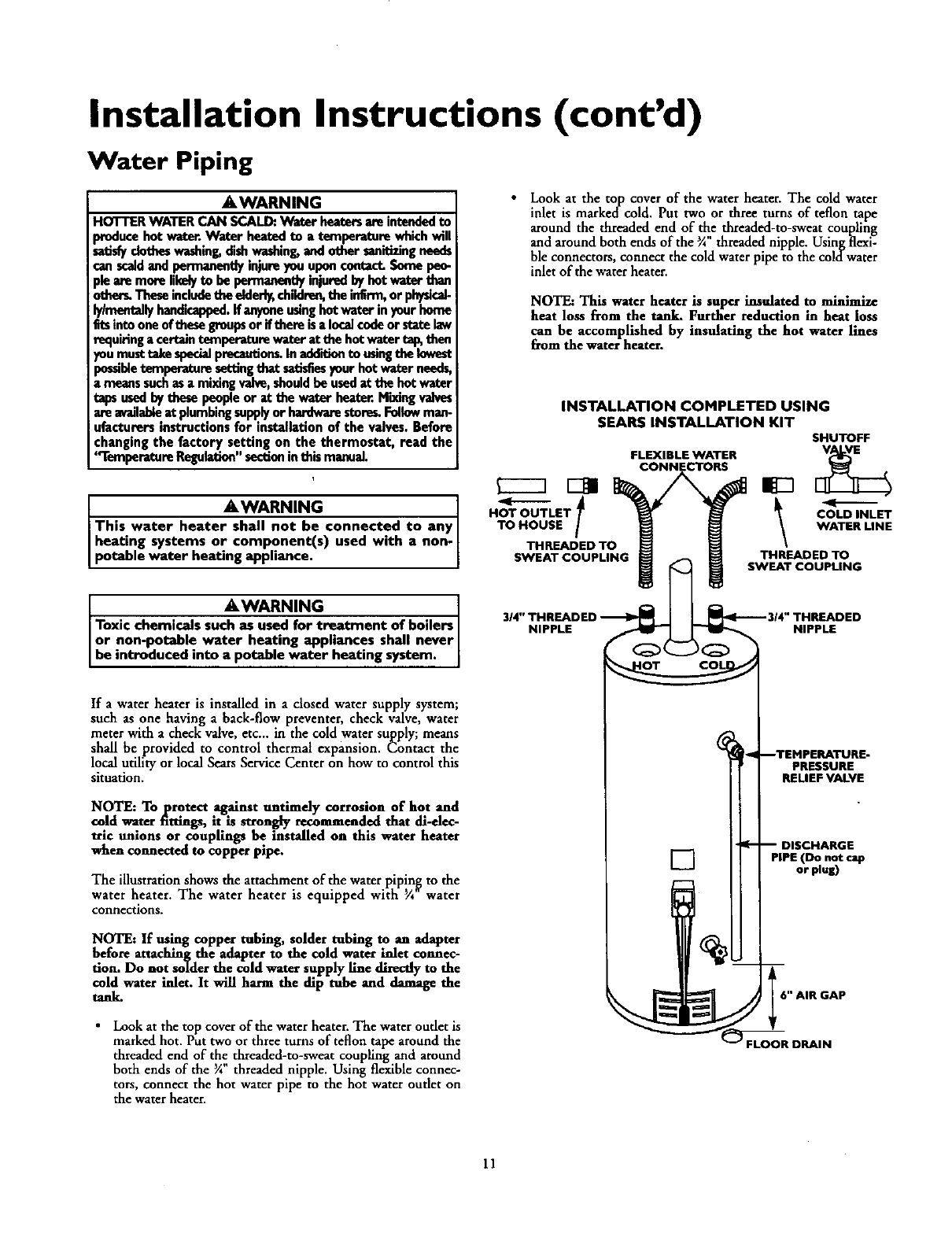
Look at the top cover of the water heater. The cold water
inlet is markedcold. Put two or three turns of teflon tape
around the threaded end of the threaded-to-sweat coupling
and around both ends of the _A"threaded nipple. Usingflexi-
ble connectors, connect the cold water pipe to the coldwater
inlet of the waterheater.
NOTE4This water heater is super insulated to minimize
heat loss from the tank. Further reduction in heat loss
can be accomplished by insulating the hot water lines
from the water heater.
INSTALLATION COMPLETED USING
SEARS INSTALLATION KIT SHUTOFF
FLEXIBLEWATER
CONNECTORS
H_T OUTLET l _ _['--
COLD INLET
TO HOUSE WATER LINE
THREADED TO
SWEATCOUPLING THREADED TO
SWEAT COUPLING
AWARNING
Toxic chemic=Issuch as used for treatment of boilers ]
or non-potable water heating appliances shall never
be introduced into a potable water heating system.
NIPPLE NIPPLE
If awater heater is installed in adosed water supply system;
such as one having aback-flow preventer, check valve, water
meter with a check valve, etc.., in the cold water supply; means
shall be provided to control thermal expansion. Contact the
local utility or local Sears Service Center on how to control this
situation.
NOTE: To protect against untimely corrosion of hot and
cold water fittings, it is strongly recommended that all-elec-
tric unions or couplings be installed on this water heater
wfien connected to copper pipe.
The illustration shows the attachment of the water piping to the
water heater. The water heater is equipped with '/4 water
connections.
NOTE: If using copper tubing, solder tubing to an adapter
before attaching the adapter to the cold water inlet connec-
tion. Do not solder the cold water supply llne directly to the
cold water inlet. It will harm the dip tube and damage the
tank.
Lookat the top coverof the water heater.The water oudet is
marked hot. Put two or three turns of teflon tape around the
threaded end of the threaded-to-sweat coupling and around
both ends of the 3A"threaded nipple. Using flexible connec-
tors, connect the hot water pipe to the hot water outlet on
the water heater.
'-,,I--TEMPERATURE.
PRESSURE
RELIEFVALVE
-- DISCHARGE
PIPE (Do not cap
or plus)
i" AIR GAP
FLOOR DRAIN
II
Installation Instructions (cont'd)
Temperature-Pressure Relief Valve
AWARNING
At the time of manufacture this water heater was provided
with a combinationtemperature-pressuresreliefvalvecertified
by a nationally recognized testing laboratory that maintains
periodic inspectionof productionof listedequipment or mate-
rials, as meeting the requirements for Relief Valves and
Automatic GasShutoffDevicesfor Hot Water SupplySystems,
and the latest edition of ANSI Z21.22 and the code require-
ments of ASME. If replaced,the valve mustmeat the require-
ments of localcodes,but not lessthan a combinationtempera-
ture and pressurerelief valvecertified as meeting the requi_-
ments for Relief Valvesand Automatic GasShutoff Devicesfor
Hot Water SupplySystems,ANSI Z21.22 bya nationally recog-
nized testing laboratory thut maintainsperiodic inspectionof
_roduction of listedequipmentor materials.
The valve must he marked with amaximum set pressurenot
to exceed the marked hydrostatic working pressure of the
water heater (150 IbsJsq.in.) and a dischargecapacitynot less
thanthe water heater inputrate asshownon the model rating
plate. (Electric heaters • watts divided by 1000 x 3415 equal
BTU/Hr. rate.)
Yourlocaljurisdictional_thority, while mandatingthe useof a
temperature-pressurerelief valvecomplyingwith ANSI Z21.22
and ASME, may require a valve model differentfrom the one
fomished with the water heater.
Compliancewith suchlocalrequirements must be satisfiedby
the installeror end userof the water heater with alocallypre-
scribed temperature-pressurereliefvalveinstalledinthe desig-
nated openingin the water heater in placeof the factory fur-
nishedvalve.
For safeoperationof the water heater,the reliefvalvemustnot
he removedfrom it'sdesignatedopeningor plugged.
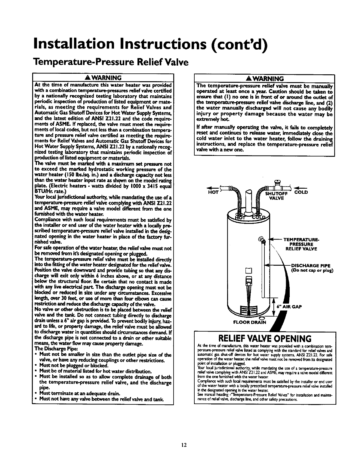
The temperature-pressurereliefvalvemusthe installeddirectly
into the fittingof the water heater designatedfor the relief vahre.
Positionthe valvedownwardand providetubingsothat anydis-
chargewill exit only within 6 inchesabove,or at any distance
below the structural floor.Be certain that no contact is made
with any liveelec_cal part. The dischargeopeningmustnot be
Mockedor reduced in sizeunder any circumstances.Excessive
length,over 30 feet, or useof more than four elbowscancause
restrictionandreducethe dischargecapacityofthevalve.
No valveor other obstructionisto he placedbetweenthe relief
valveand the tank. Do not connecttubing directlyto discharge
drainunlessa 6" air gapis provided.Topreventbodilyinjury,haz-
ard to life,or property damage,the relief valvemusthe allowed
to dischargewater in quantitiesshouldcircumstancesdemand.If
the dischargepipe is not connectedto a drain or other suitable
means,the water flowmaycausepropertydamage.
The DischargePipe:
Must not be smaller in size than the outlet pipe size of the
valve,or haveanyreducingcouplingsor other restrictions.
Must not be pluggedor blocked.
Must he of material listedfor hot water distribution.
Must be installedso as to allow complete drainage of both
the temperature-pressure relief valve, and the discharge
pipe.
Mustterminate at an adequatedrain.
Must not haveany valvebetween the relief valveand tank.
AWARNING
The temperature-pressure relief valve must be manually
operated at least once ayear. Caution should be 'mlconto
ensure that (I) on one is in front of or around the outlet of
the temperature-pressure relief valve dischargeline, and (2)
the water manually discharged will not cause any bodily
injury or property damage because the water may be
extremelyhot
If after manually operating the valve, it fails to completely
reset and continuesto release water, immediately dose the
cold water inlet to the water heater, follow the draining
instructions, and replace the temperature-pressure relief
valvewith a now one.
VALVE
PRESSURE
RELIEF VALVE
[] (Do not cap or plug)
6" AIR GAP
FLOOR DRAIN
RELIEFVALVEOPENING
At the time of manufacture,this water heater wasprovidedwi_ a c0mbinariontem-
perature-pressurerelief v_ve listedas complyingwith the stinderdfor relief valvesand
automaticgasshut-offde_cesfor hot water supplysystems,ANSI Z21.22. For safe
operarionof the water heater,the relief valvemust not be removedfromits designated
_i_ of installationor plugged,
ur Iool jutisdicdonalauthori_,while mandatingthe useof atemperatur_pre_sure
retiefvalvecomplyingwith ANSI Z21.22 andASHE mayrequire avalvemodeldifferent
from the o_efurnishedwith the water heater
Compliancewith suchlocalrequirements must be satisfiedbythe installeror end user
of the wau_rheaterwith a Iocabyprescribedtemperature-pressurerelief valve installed
inthe designatedopeningin the water be_te_
See manualhe_ding-'_lemberature-PressureReliefValves"for installarionandmainte-
nanceof relief valve,dischargeline, andother safe_ precautions.
12
Installation Instructions (cont'd)
Filling the Water Heater
A CAUTION
Never usethis water heater unlessit is completely filled with
water. To prevent damage to the tank, the tank must be filled
with water. Water must flow from the hot water faucet
beforeturning "ON" gasto the water heater,
To fill the water heater with water:
•Close the water heater drain valve by turning the handle to
the right (clockwise). The drain valve is on the lower front of
the water heater.
• Open the cold water supply valve to the water heater.
NOTE: The cold water supply valve must be left open
when the water heater is in use.
•To insure complete filling of the tank, allow air to exit by
opening the nearest hot water faucet. Allow water to run
until a constant flow is obtained. This will let air out of the
water heater and the piping.
• Checkall newwaterpipingforleaks. Repair as needed.
Venting
&WARNING
VENT DAMPERS - Any vent damper, whether it is operated
thermally or otherwisemustbe removedifits useinhibitsprop-
er draffingof the wator heater.
Thermally Operated Vent Damper_ Gas-firedwater heaters
having thermal efficiency in eacess of 80%may produce a rela-
tively low flue gas temperature. Such temperatures may not be
high enough to properly open thermally operated vent
dampers_Thiswouldcausespillageof flue gasesand maycause
carbonmono_de poisoning.
Vent dampersmustbear evidenceof certificmionascomplying
with the latest edition of Ame_can Na_onal Standard ANSI
7.21.68(ANSI 7.21.66 & 67, respectively,cover elecUicallyand
mechanicallyactuated vent dampers).Beforeinstallationof any
rant damper,consultyourlocalSearsServlceCenter ortbe gas
utilityfur further information.
&WARNING
To insure proper venting of this ges-fired water heater, the
correct vent pipe diameter must be utilized. Anyadditionsor
deletionsof ntber gas applianceson a common vent with this
water heater may edvereely affect the operation of the water
heavenConsultthe localSears ServiceCanter or gasutility If
anysuchchangesare planned.
For proper venting in certain installations, a larger diameter vent
pipe may he necessary. Due to great variances in installations,
unforeseeable by the manufacturer of the water heater, 7ou must
consult your gas company to aid you in determining the proper
venting for your water heater from the vent tables in the latest
edition of the National Fuel Gas Code ANSI Z223.1, also
referred to as NFPA 54.
Check the venting system for signs of obstruction or deteriora-
tion and replace if needed.
The combustion and ventilation air flow must not be obstructed.
AWARNING I
_ or ,dete,rior.ated.Vetosystemsmaypresomaserlous
healthriskorasphy_Cian.
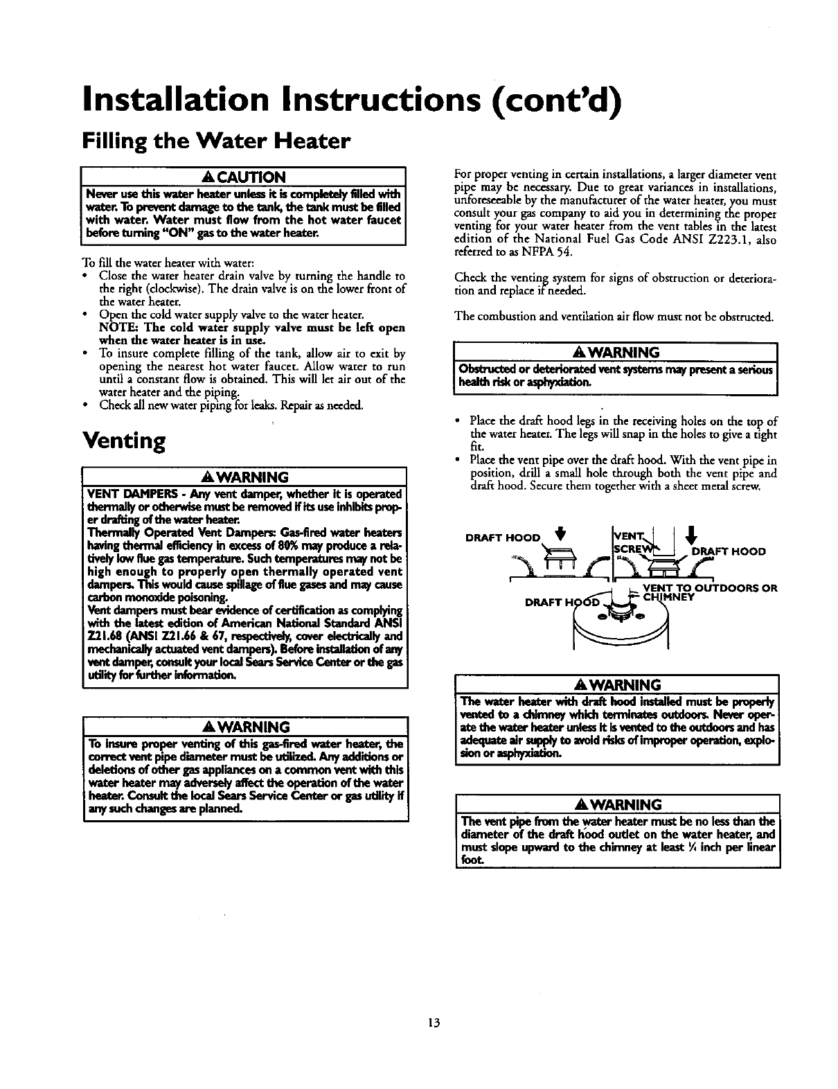
•Place the draft hood legs in the receiving holes on the top of
the water heater.The legs will snap in the holes to give a tight
fit.
•Place the vent pipe over the draft hood. With the vent pipe in
position, drill a small hole through both the vent pipe and
dra_ hood. Secure them together with asheet metal screw.
DRAFT HOOD _[VENT,.] I _
0_[5CRE._._ DRAFT HOOD
DRAFT HgO_ V_!_TNE,OOUTDOOR$ OR
JEWARNING I
The water heater with draft hood installed must be properlyI
vanted to a chimneywhkh terminates outdoof_ Never aper- ]
8_ethe v,_ heZorunhmit israntedm _aeontdeersandhasI
adequateair supplyto woid risksof improper aperation, eaplo-
sionorasphyxiation.
AWARNING
The Vent pipe from the wator heater must be no lessthan the
diameter of the draft hood outlet on the water heater, and
must slope upward to the chimney at least ¼inch per linear I
Lfuot
13
Installation Instructions (cont'd)
Venting (cont'd) Gas Piping
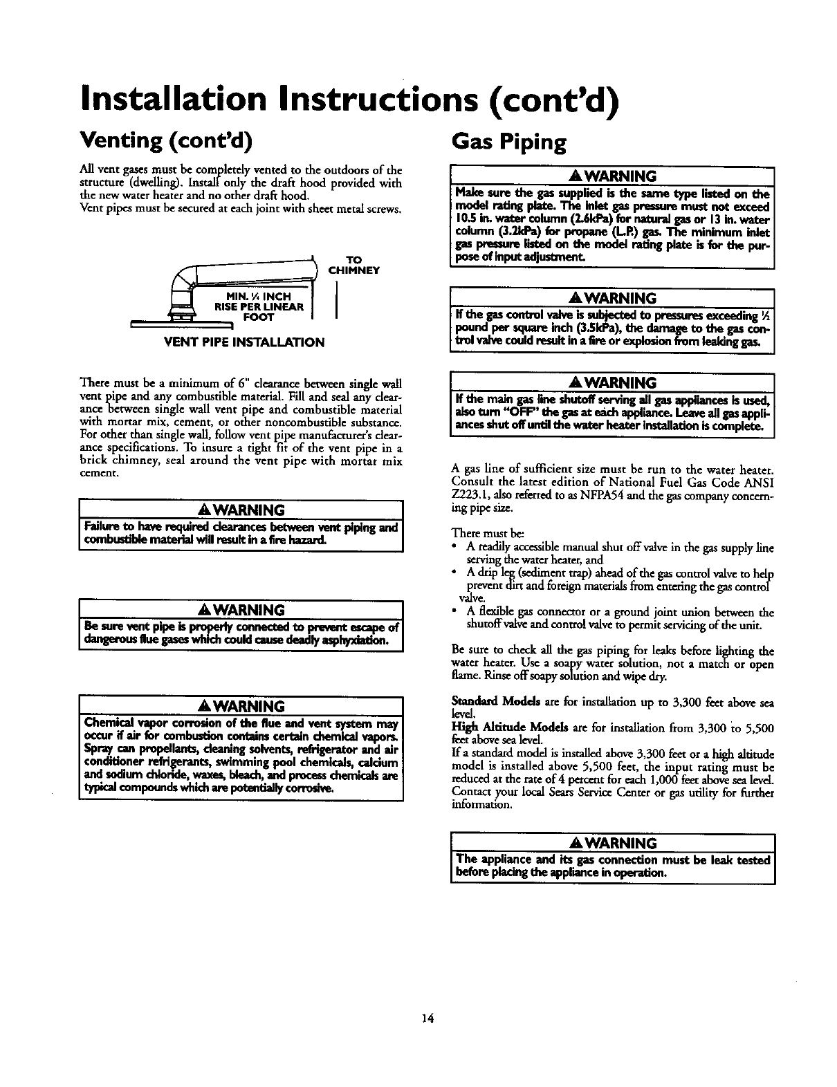
All vent gases must be completely vented to the outdoors of the
structure (dwelling). Installonly the draft hood provided with
the new water heater and no other draE hood.
Vent pipes must be secured at each joint with sheet metal screws.
TO
_R I CHIMNEY
I
VENT PIPE INSTALLATION
&WARNING
Make sure the gas supplied is the same type listed on the
model feting piete. Tbe inlet gas pressure must not exceed
10.5i_ water column (2.6kPa) for natural gasor 13 in.water
column (3.2kPa) for propane (L.R) gas.The minimum inlet
gas pressure6-tod on the model reting pl_ is for the pur.
poseof input odjustmont.
AWARNING
If the gascontrol _is subjectedto pressuresexceeding½
pound per square inch (3.SkPa), the damage to the gascon-
trel valvecouldresultin a Ereor explosionfrom leaking
There must be aminimum of 6" clearance between single wall
vent l)ipe and any combustible material. Fill and seal any dear-
ance t_etween single wall vent pipe and combustible material
with mortar mix, cement, or other noncombustible substance.
W " ' '
or other than single wall, follow vent pipe manufacturers dear-
ance specifications. To insure atight fit of the vent pipe in a
brick chimney, seal around the vent pipe with mortar mix
cement.
A, WARNING I
Failureto haverequireddearancesbetweenventpipingandI
€ombum'idematerialwillresultina firehazard. I
A WARNING I
Be surevontpipeispropedyconnectedto pm,_nt escapeof
dongemusguegeseswhichcouklcausedeadlyasphyxiation.
AWARNING
Chemical vapor corrosion of the flue and vent system may
occur if air for combustioncontainscertain chemicalvapor_
Spray can propellants,denning solvents,refrigerator and air
conditioner refrigerants, swimming pool chemicals,calcium
and sodium chloride,waxes,bleach,and processcbemiadsare
compoundswhich are potentiallycon'oslve.
AWARNING I
If tbe maingaslionshutoffservingall gasappliancesisused,I
alsoturn"OFF" thegasat e_h appliance.Leaveallgasappli-
ancesshutoffuntilthe waterheaterinstallationiscumpiete.
Agas line of suPBcient size must be run to the water heater.
Consult the latest edition of National Fuel Gas Code ANSI
Z223.1, _so referred to as NFPA54 and the gas company concern-
mg pipe size.
There must be:
i A readily accessible manual shut off valve in the gas supply line
serving the water heater, and
A drip leg (sediment trap) ahead of the gas control valve to help
prevent dirt and foreign materials from entering the gas control
Valve.
•A flexible gas connector or a ground joint union between the
shutoffvalve and control valve to permit servicing of the unit.
Be sure to check all the gas piping for leaks before li__,htin_the
water heater. Use a soapy water solution, not amatc_ or _pen
flame. Rinse offsoapy solution and wipe dry.
Standard Modds are for installation up m 3,300 feet above sea
levd.
High Altitude Models are for installation fi'om 3,300 to 5,500
feet above sea level.
Ifa standard model is installed above 3,300 feet or a high altitude
model is installed above 5,500 feet, the input rating must be
reduced at the rateof 4 percent for each 1,000 feet above sea level.
Contact your local Sears Service Center or gas udlity for further
information.
&WARNING
The applianceand its gasconnectionmust be leak tested
beforeplacingdieapplianceinoperation.
14
Installation Instructions (cont'd)
AWARNING
•The appliance and its individualshutoff valvemust be discon-
ne_edfnxnthetm sup_yp_ngsystemduringanypr_u_
testing of the gas system at test pressures in excessof V,
poundper squareinch(3.Sl#a).
•Tbe appliance mustbe isolatedfrem the gassopply pipingsys-
tem by dosingits individualmanualshutoff valveduring any
pressuretestieg of the gassupplypipingsystem at test pre_
sumsequalor lessthan ½poundper square inch(3.SkPa).
AWARNING I
Use pipe joint compound or teflon tape marked as being I
resistantto the action of peWoleum[Propane (LR)] gases. I
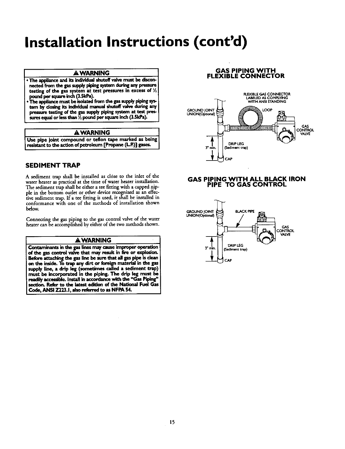
SEDIMENT TRAP
A sediment trap shall be installed as cldse to the inlet of the
water heater as practical at the time of water heater installation.
The sediment trap shall be either a tee _tting with a capped nip-
ple in the bottom outlet or other devicerecognizedas an effec-
tive sediment trap. Ira tee 8tting is used, it shaUbe installed in
conformance with one of the methods of installation shown
below.
Connecting the gas piping to the gas control valveof the water
heater can be accomplished by either of the two methods shown.
AWARNING
Contaminants inthe gaslines may causeimproper operation
of the gas con_ol valve that may result in tim or explesion.
Befora attaching the gasline be sum thnt =11gaspipe isdexn
on the ieside. To trap any dirt or fo_qgn material in the gas
supply line, adrip leg (sometimes called asediment trap)
must be incorporated in the piping. The drip leg must be
readilyaccessible.Installin accordancewith the "Gas Piping"
section.Rofer to the Intest edition of the National Fuel Gas
Cede, ANSI Z223.1, also rofemsdto as NFPA 54.
GAS PIPING WITH
FLEXIBLE CONNECTOR
FLEXIBLE GAS CONNECTOR
LABELEDASCOMPLYING
c°NT °
VALVE
GAS PIPING WITH ALL BLACK IRON
PIPE TO GAS CONTROL
GROUND JOINT BLACK PIPE
UNION(Optional)
DRIP LEG
(Sedimenttrap)
GAS
CONTROL
VALVE
CAP
15
Installation Instructions (cont'd)
Installation Checklist
BEFORE LIGHTING THE PILOT:
•Check the gas lines for leaks.
a. Use a soapy water solution. DO NOT test for gas leaks
usinga match or open flame.
b. Brush the soapy water solution on all gas pipes, joints and
fittings.
c. Check for bubbling soap. This means you have a leak.
Turn _OFF" gas andmake the necessary repairs.
d. Recheck for leaks.
e. Rinse off soapy solution and wipe dry.
•Is the new temperature-pressure relief va2je properly installed
and piped to an adequate drain? See Temperature-Pressure
Relief Valve" section.
•Are the cold and hot water lines connected to the water
heater correctly? See "Water Piping" instructions in the
_Installation Instructions" section.
•Is the water heater completely filled with water. See Fdhng
instructions in the "Installation Instructions" section.
• Will a water leak damage anything? See the _Facts to
Consider About the Location"section.
•Is there proper clearance between the water heater and any-
thing that might catch fire? See the "Factsto Consider About
the Location section.
• Do you have adequate ventilation so that the water heater
will operate properly? See "Combustion Air and Ventilation"
in the "Facts to Consider About the Location"section.
•Is the draft hood vent piping properly secured? See "Venting"
lnstruct;ons In the Installanon Instrucuons section.
• Is there proper clearance between the vent pipe and anything
that might catch on fire? See "Venting" instructions in the
"InstalLation Instructions _ section.
• Is the vent pipe properlysloped and does the vent terminate
outdoors? See "Venting instructions in the "Installation
Instructions" section.
•Do you need to call your gas company to check the gas pipe
and its hookup?
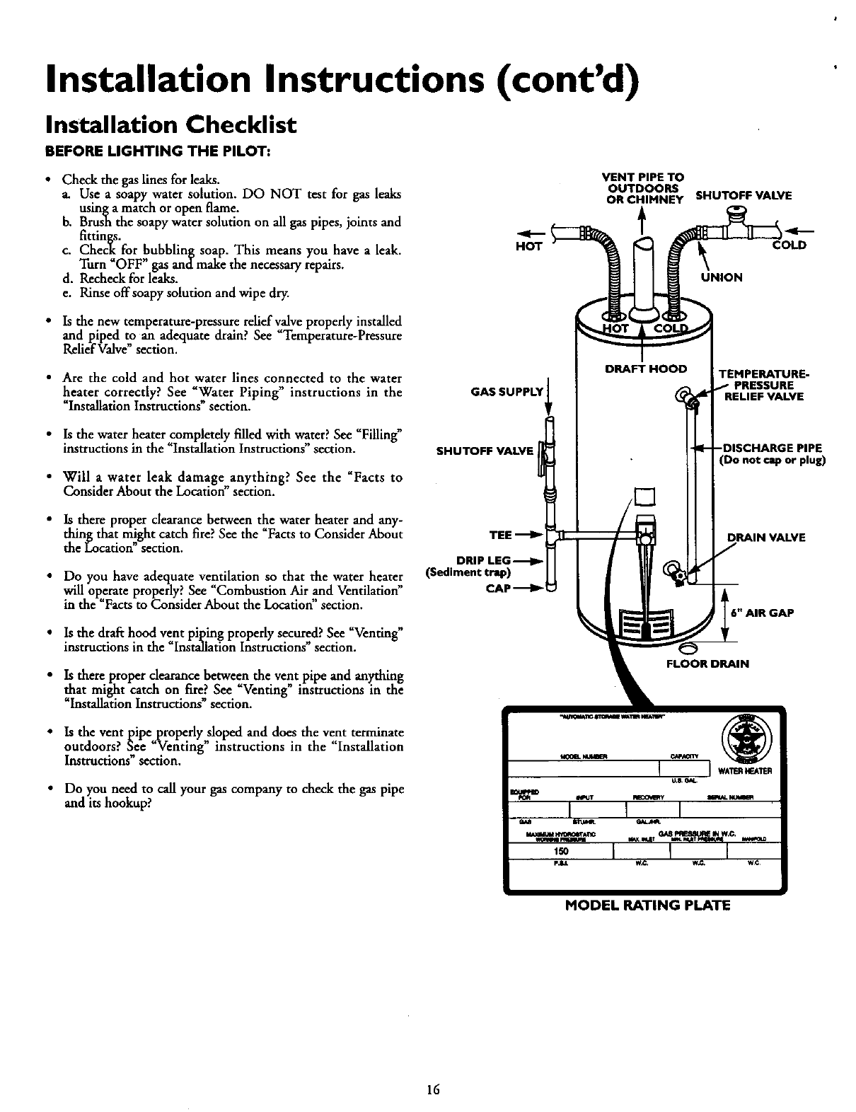
HOT
VENT PIPE TO
OUTDOORS
OR CHIMNEY SHUTOFF VALVE
t
_ COLD
UNION
GAS SUPPLY
SHUTOFF VALVE
DRIP LEG
(Sediment trap)
CAP _1
DRAFT HOOD TEMPERATURE-
PRESSURE
(Do not cap or plug)
DRAIN VALVE
L6" AIR GAP
FLOOR DRAIN
MODEL RATING PLATE
16
Operating Instructions
Lighting
AWARNING
BEFORE LIGHTING [PROPANE (L.R) GAS WATER
HEATERS]:Propane(LR) gasis heavierthan air.Shouldthem
be a leak in the system,the gaswill settle near the ground.
Basements,crawl spaces,skirted areasunder mobile homes
(evenwhenventilated),closetsand_ below ground_will
serve as pocketsfor the accumulatmn of this gas. Before
attemptingto lightor relightthe water heater_pilotor turning
ona nearbyelectricallightswitch,beabsolutelysurethere isno
accumulatedgasinthe are_ Searchforodorofgasbysniffingat
groundlevelinthe vicinityof the appliance.If odorisdetected,
foliowstepsindicatedat "For YourSafety"on the coverpageof
thismanualthen leavethe premise_
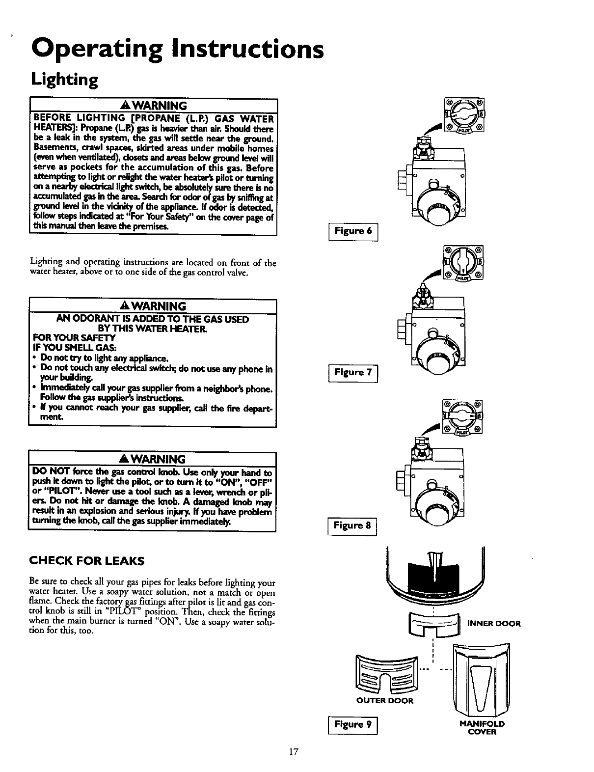
Lighting and operating instructions are located on front of the
wa-terheater, above or to one side of the gas control valve.
AWARNING
AN ODORANT IS ADDED TO THE GAS USED
BY THIS WATER HEATER.
FORYOUR SAFETY
IFYOU SMELLGAS:
Do not try to light;myappliance.
Do nottouch anyelectricaJswitch;do not useanyphonein
_n_trbuilding. .
iatelycallyour gassupplierfrom anelghhor's phone.
Foflowthe gassupplier_instrectlons.
If youcannot reach your gassupplier,caJlthe fire deport-
ment.
AWARNING
DO NOT forcethe gascontrolknob.Useonlyyoor handeo
pushit down to lightthe pilot, or to tom it to '_)N", "OFF"
or "PILOT". Never use atool suchasalever,wrench or pli-
orL Do not hit or damngethe Imob.A damagedImob may
!resultin an explosionandseriousinjur_ If you have problem
turningthe knob,callthe gassupplierimmediately.
IFigure 6 ]
Figure 7 ]
Figure 8 ]
CHECK FOR LEAKS
Be sure to check all your gas pipes for leaks before lighting your
water heater. Use a soapy water solution, not a match or open
flame. Check the factory gas _ttings after pilot is lit and gas con-
trol knob is still in PILOT pos!tion. Then, check the fittings
when the main burner is turned ON". Use a soapy water solu-
tion for this, too. INNER DOOR
i
..." _..
OUTER DOOR
[ Figure 9 ] MANIFOLDcovER
17
Operating Instructions (cont'd)
Lighting label on the water heater as it appears above the thermostat
FOR YOUR SAFETY READ BEFORE LIGHTING
WARNING I
If you do not follow these instructions exactly, e fire or explosion
may result causing property damage, personal injury or loss of life,
A. Thisappliancehas a pilotwhichmustbe lightedby
hand,Whenlightingthepilot,followtheseinstructions
exactly.
B,BEFORELIGHTINGsmellallaroundtheappliancearea
forgas. Be sureto smellnextto the floorbecause
somegasisheavierthanairandwillsettleonthefloor.
WHATTODOIFYOUSMELLGAS
• Donottryto lightanyappliance.
•Donottouchany eioatricswitch;do not use any
phoneinyourbuilding.
•Immediatelycellyour gassupplierfroma neighbor's
phone.Fat{owthegaseupplinr'sthstruations,
•If youcannotreachyourgassupplier,cell thefire
_rtment.
C.Useonlyyourhandto pushin orturnthegascontrol
knob.Neverusetools.If the knobwillnatpushinor
turnbyhand,don'ttryto repairIt,calla qualifiedser-
vicetechnician.Forceor attemptedrepairmayresult
Inafireorexplosion.
D.Donotusethisapplianceif anyparthasbeenunder
water.Immediatelycalla qualifiedservicetechnician
to inspecttheapplianceandto replaceanypartofthe
controlsystemandanygas controlwhichhasbeen
underwater.
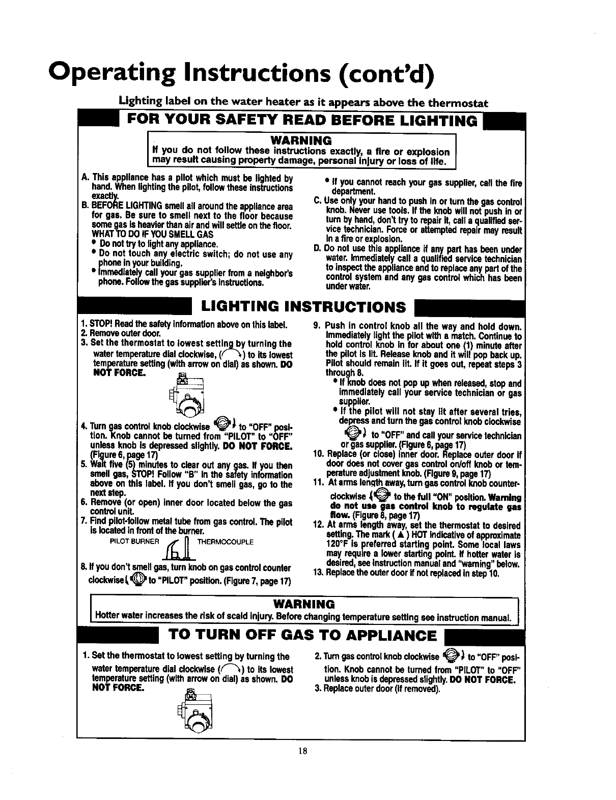
LIGHTING INSTRUCTIONS
I.STOP!Readthesafetyinformationaboveonthislabel.
2.Removeouterdoor.
3, Setthe thermostatto lowestsettin_byturningthe
watertemperaturedialclockwise,(( _) to itslowest
temperaturesetting(witharrowondial)asshown.DO
NOT FORCE. _
4.'rumgascontrolknobclockwiv se _'_') to "OFF"posi-
tion.Knob cannotbe turnedfrom"PILOT" to "OFF"
unlessknobIs depressedslightly.DO NOT FORCE.
(Figure6, psga17)
5. Waitfive(5) minutesto clearoutanygas.If youthen
smellgas,STOP!Follow"B" in thesafetyinformation
aboveonthislabel.If youdon'tsmellgas,goto the
nextslap.
6. Rernove(or open)inner doorlocated beiow thegas
controlunit.
7. Findpilot-follOwmetaltubefromgascontrol.Thepilot
islocatedinfmatofthe burner,
PILOT BURNER _ _ THERMOCOUPLE
.L.E=E.a_
8,It youdon'tsmellgas,turnknobongascontrolcounter
deckwios_=(_ ' to"PILOT"position.(Figure7, page17)
9. Pushin control knob all the wayand holddown.
Immediatelylightthe pilotwitha match.Continueto
holdcontrolknobinfor aboutone(1) minuteafter
the pilotIs lit.Releaseknobandit willpop backup.
Pilotshouldremainlit. If It goesout, repeatsteps3
through8.
•If knobdoesnotpopupwhenreleased,stopand
immediatelycallyourservicetechnicianor gee
supplier.
•if the pilot will not stay_lt after severaltries,
depress_) andturn,thegascontrolknobclockwise
_" to OFF andcallyourservicetechnician
orgassupplier.(Figure6, page17)
10. Replace(ordose)innerdoor.Replaceouterdoorif
doordoesnat covergas controlon/offknobortem-
peratu4'eadjustmentknob.(Flgm 9,page17)
11. Atarmslengthaway,turngascontrolknobcounter.
deckwise_tothefull "ON"position.Warnthg
do not use gas control knob to regulate gas
flow. (FIguroa,page17)
12.At armslengthaway,set the thermostatto desired
setting.Themink(•) HOTindicot[veofapproximate
120°Fis preferredstartingpoint.Somelocallaws
mayrequirea lowerstertlngpoint.If hotterwaterIs
desired,seeInstructionmanualand"warning"below.
13.ReplacetheouterdoorIf notreplacedinstep10.
1, Setthe thermostatto lowestsettingby turningthe
watertemperaturedialdookwlsa(("-_) to its lowest
temperaturesetting(witharrowondial)asshown.DO
NOTFORCE,
I WARNING I
Hotterwaterincreasesthe riskof scaldInjury.Beforechangingtemperaturesettingseeinstructionmanual,w
TO TURN OFF GAS TO APPLIANCE
2."rumgascontrolknobclockwise_ _to"OFF"posi-
tion. Knobcannotbe turnedfrom"PILOT"to "OFF"
unlessknobis depressedslightly.DO NOTFORCE.
3. Replaceouterdoor(ifremoved).
18
Operating Instructions (cont'd)
Temperature Regulation
Due to the nature of the typical gaswaterheater, the watertem-
_oeraturein certain situations may var_ up to 30°F higher or
wet at the point of usesuch as, bathtuns, showers, sink, etc.
This means that when the temperature adjustment dial is set at
the mark approximating 120°F, the actual watertemperature at
any hot water tap could beas high as 150°F or as low as 90°F.
Any waterheater's intendedpurpose is to heat water.Hot water
is needed for cleaning (bodies, dishes, clothing). Hot water will
present a scald hazard. Depending on the time element, and the
people involved (norton[adults, children, toddlers, elderly,
infirm, etc.) scalding may occurat differenttemperatures.
AWARNING
HOTTER WATER CAN SCALD,"Water heatersare intendedto
producehot water. Water heated to atemperature whichvdU
satisfyclotheswashing,dishwashing,and other sanitizingneeds
canscaldand permanontly injureyou_on conta_ Sornepeo-
ple aremore likelyto be penmnently injuredbyhot water than
others.Theseincludethe elderly,children,the infirm,or physical-
lylmontallyhandicapped.If anyoneusinghot water in your home
fitsintooneof thesegroupsor if there isa localcodeor state law
requiringa certaintemperaturewater at the hot watertaR then
youmusttakespecialpmcautior_ Inadditionto usingtheIowes_
possibletemperature settingthat satisfiesyourhot water needs
a meanssuchasa mixingvalve,shouldbe usedat the hot watel
tapsusedbythese peopleor at the water heater.Mixingvalves
areavailableat plumbingsupplyor hardwarestores.Followman-
ufacturers instructions for installation of the valves. Before
changing the factory setting on the thermostat, read the
I'q'emperatureRegulation"sectioninthismanual.
AWARNING
Neverallowsmallchildrento useahot wotertap,orto draw
[ theirownbathwater.Neverleaveachildorhandicappedper-
Isonunattondedinabathtoborshower.
The thermostat of this waterheater has been factory set at its
lowestposition, to reduce the riskof scald injury. It is adjustable
and must be reset to the desiredtemperature setting. The mark
(A) HOT indicative of approximately 120°F is the preferred
startin_ point. Some states have a requirementfor a lowerset-
ring. Iryou need hotter water, follow directionsfor temperature
adjustment, but bewareof the warningsin this section.
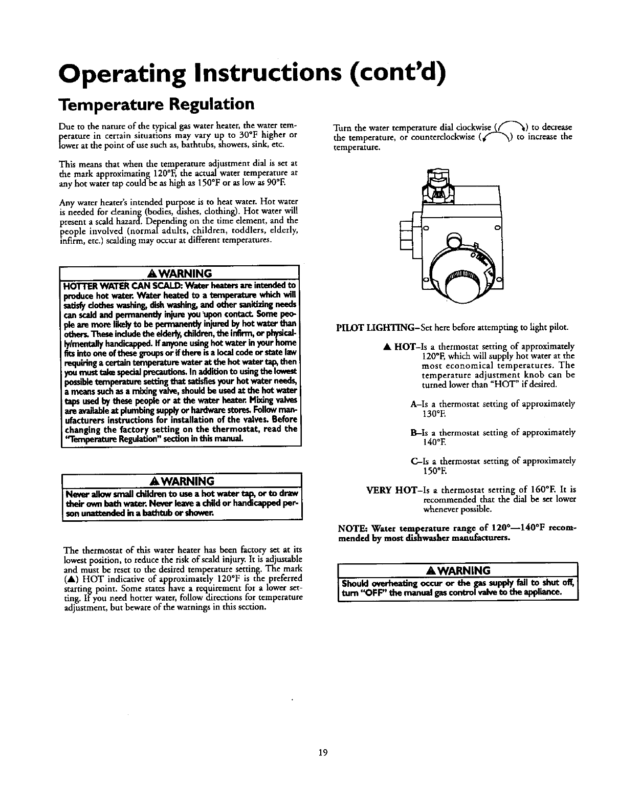
Turn the water temperature dial clockwise_("-"x_) to decrease
the temperature, or counterclockwise (€"- _"_) to increase the
temperature,
PILOT LIGHTING-Set here before attempting to light pilot.
•HOT-Is a thermostat setting of approximately
120°F, which will supply hot water at the
most economical temperatures. The
temperature adjustment knob can be
turned lower than "HOT" if desired.
A-Is athermostat setting of approximately
130°E
B-Is a thermostat setting of approximately
140°E
C-Is athermostat setting of approximately
150°E
VERY HOT-Is a thermostat setting of 1600E It is
recommended that the dial be set lower
whenever possible.
NOTE: Water temperature range of 120°--140°F recom-
mended by most dishwasher manufacturers.
AWARNING [
Should overheating occur or the gas supply fail to shot off,]
Ourn OFF"_manualgascontrolvalveto theappliance. I
19
Service and Adjustment
Tank (Sediment) Cleaning
Sediment build-up on the tank bottom may create varying
amounts of noise, and if left in the tank will cause premature
tank failure. In some water areas, you may not be able to drain
all sediment deposits by simply draining the tank. In these cases
Mag Erad (part no. 23600) can be used to help remove the sedi-
ment deposits. This m_ty be ordered from the ,Sears Service
Center. For ordering, refer to the "Parts Order List section.
Venting System Inspection
At least once a year a visual inspection should be made of the
venting system. You should look for:
• Obstructions which could cause improper venting. The com-
bustion and ventilation air flow must not be obstructed.
i Damage or deterioration which could cause improper vent-
ing or leakage of combustion products.
Rusted flakes around top of water heater.
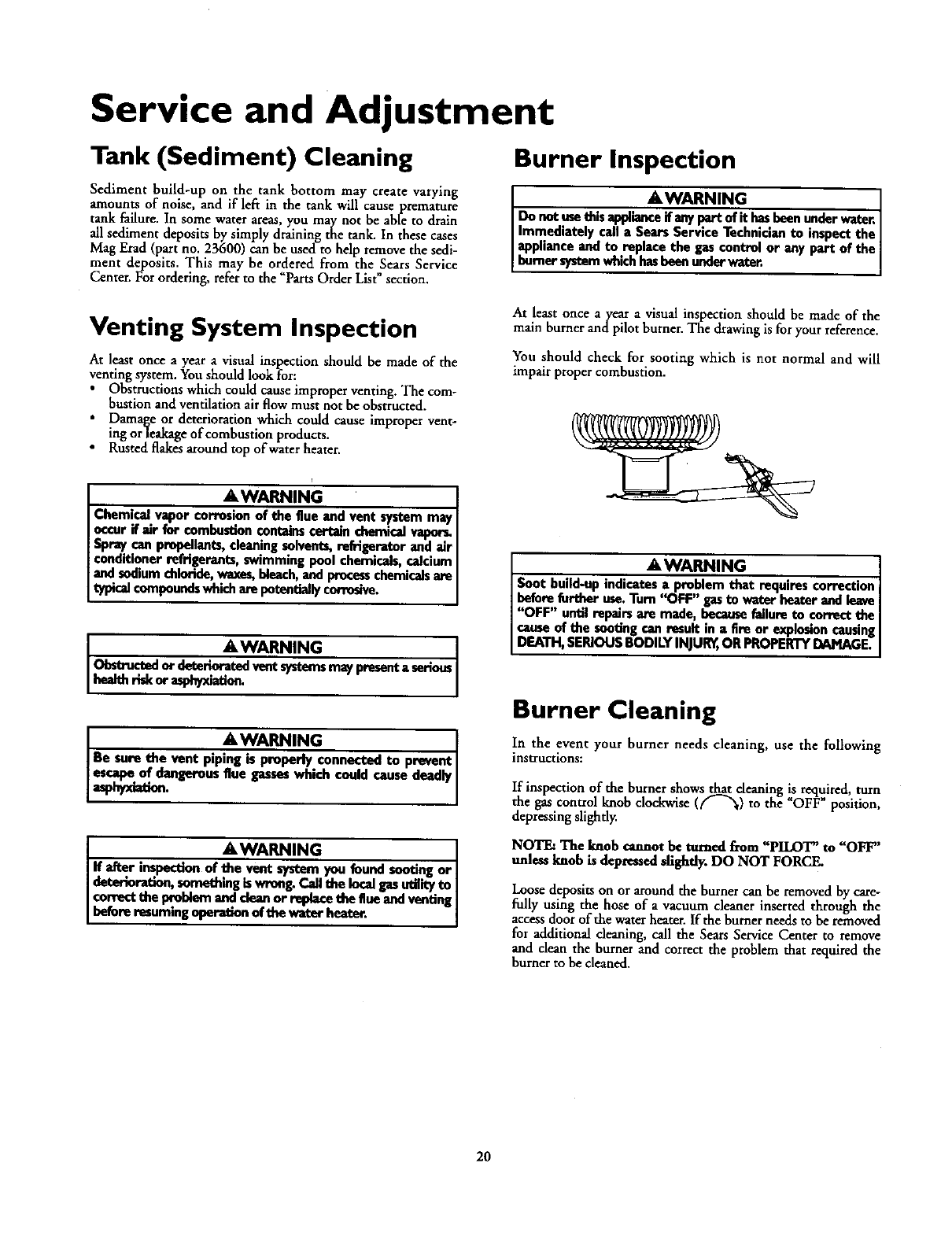
Burner Inspection
AWARNING
Donotusethisq_0_mceif_y pertof It hasbeenundervr_er.
Immediatelycalla SearsServiceTechnicianto inspectthe
applianceandto replacethe gascontrolor any partof the
burnersystemwhichhasbeenunderwater.
At least once ayear avisual inspection should be made of the
main burner andpilot burner. The drawing is for your reference.
You should check for sooting which is not normal and will
impair proper combustion.
i
AWARNING
Chemical vapor corrosionof the flue and vent system may
occurif air for €ombustion€ontainscert_ chemi_ vapors,
Spray can propellants, cleaning solvents,refrigerator and air
conditioner refrigerants, swimming pool chemicals, calcium
and sodiumchloride,waxes,bleach,andprocesschemicalsare
typical compoundswhich arepotently corrosive.
AWARNING I
0bstructed er deteriorated vent sFstoms may peesent aserious
health mk or asphyxiation.
&WARNING I
Be sure the vent piping is properly connected to prevent I
[___d_.. _'ous flue gas. which could cause deadly I
JkWARNING
[ If after inspection of the vent system you found sootingor [
Idete_oration, something iswrong. Call the localgasutifity to I
_€_vect ti_ problem and dezn or _e the Bueand venting_
Ibufurer=oming ofthe*' erhe er' I
AWARNING
Soot build-up indicat_s a problem that requires correction
before further use.Turn "OFF" gasto water heater and leave
"OFF" until repairs am made, becausefailure to correct the
[cause of the sootingcan result in a fire or explosioncausing
IDEATH, SERIOUSBODILY INIU_, OR PROPERTYDAMAGE.
Burner Cleaning
In the event your burner needs cleaning, use the following
instructions:
If inspection of the burner shows that deauing is required,turn
the gas control knob clockwise(_"_) to the _OFT" position,
depressingslighdy.
NOTE: The knob cannot be turned fTom"PILOT" to "OFF"
unless knob is depressedsfigfitly. DO NOT FORCE.
Loose deposits on or around the burner can be removed by care-
fully using the hose of a vacuum cleaner inserted through the
access door of the water heater. If the burner needs to be removed
for additional cleaning, call the Sears Service Center to remove
and dean the burner and correct the problem that required the
burner to be cleaned.
20
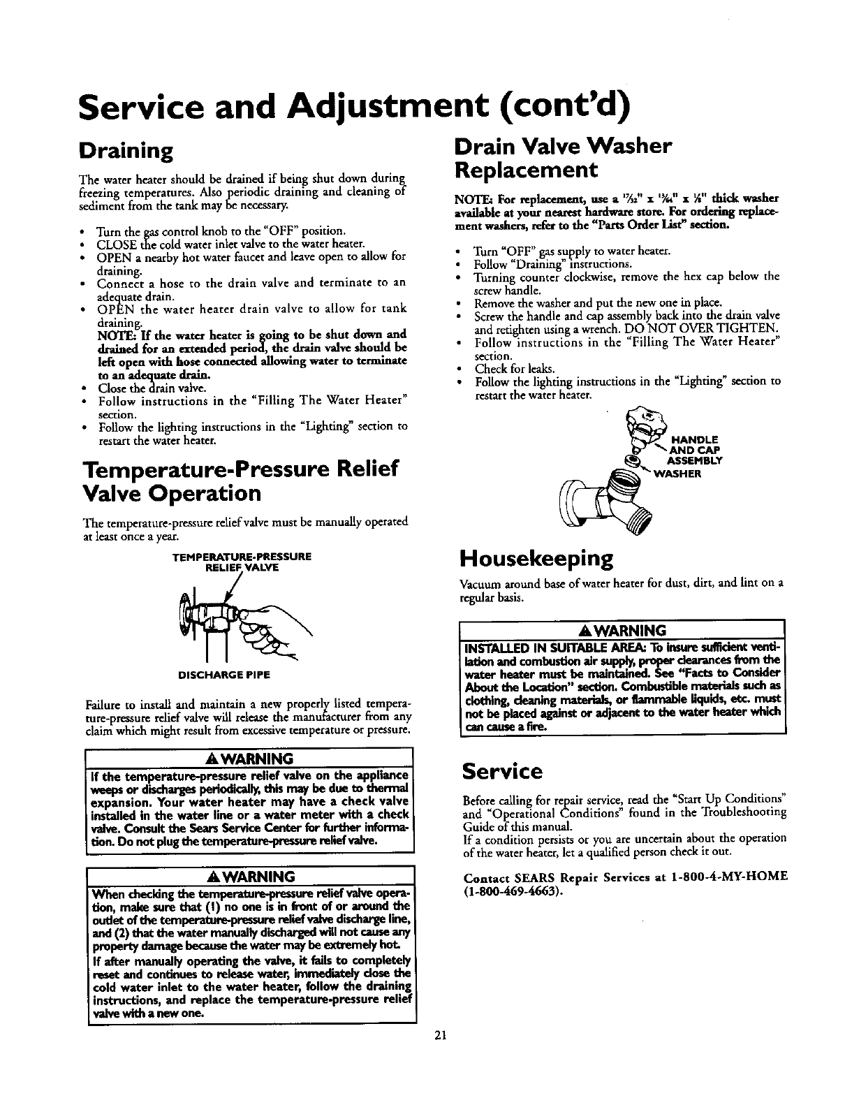
Service and Adjustment (cont'd)
Draining
The water heater should be drained if being shut down during
freezing temperatures. Also periodic draining and cleaning of
sediment from the tank may be necessary.
Turn the gas control knob to the "OFF" position.
CLOSE the cold water inlet valve to the water heater.
OPEN anearby hot water faucet and leave open to allow for
draining.
Connect ahose to the drain valve and terminate to an
adequate drain.
OPEN the water heater drain valve to allow for tank
draining.
NOTE: If the water heater is going to be shut down and
drained for an extended period, the drain valve should be
left open with hose connected allowing water to terminate
to an adeq*mte drain.
•Close thedrain valve.
•Follow instructions in the _Filling The Water Heater"
section.
• Follow the lighting instructions in the "Lighting" section to
restart the water heater.
Temperature-Pressure Relief
Valve Operation
The temperature-pressure relief valve must be manually operated
at least once a year.
TEMPERATURE-PRESSURE
Drain Valve Washer
Replacement
NOTE: For replacement,use a l_,, x 'Ya"• _" thick washer
available at your nearesthardwarestore. Forordering replace-
ment washers,referto the "Parts OrderList"section.
i Turn "OFF" gas supply to water heater.
Follow Draining" instructions.
Turning counter clockwise, remove the hex cap below the
screw handle.
Remove the washer and put the new one in place.
Screw the handle and cap assembly back into the drain valve
and retighten using awrench. DO NOT OVER TIGHTEN.
Follow instructions in the _Filling The Water Heater"
section.
Check for leaks.
Follow the lighting instructions in the "Lighting" section to
restart the water heater.
ASSEMBLY
Housekeeping
Vacuum around base of water heater for dust, dirt, and lint on a
regular basis.
DISCHARGE PIPE
Failure to install and maintain anew properly listed tempera-
ture-pressure relief valve will release the manufacturer from any
claim which might result from excessive temperature or pressure.
AWARNING
If the temperature-pressure relief valve on the appliance
weeps or discharges periodically, this may be due to thermal
expansion. Your water heater may have a check valve
installed in the water line or a water meter with a check
valve. Consult the Sears Service Center for further informa-
tion. Do not plug the temperature-wessure relief valve.
AWARNING
When checkingthe tempereture-pressure relief valve opera-
don, make sure that (I) no one is in front of or around the
outlet of the temperature-pressure relief valvedischargeline,
and (2) that the water manually dischargedwill not causeany
woperty damagebecausethe water may be extremely hot.
If after manually operating the valve, it fails to completely
reset and continuesto release water, immediately closethe
cold water inlet to the water heater, follow the draining
instructions, and replace the temperature.pressure relief
valve with a now one.
AWARNING
INSTALLED IN SUITABLE ARIEA_To insuresufficientventi-
lation and combustionair supply,proper dearances from the
water heater must be maintained. See "Facts to Consider
About the Location" section.Combustible _s such as
dothln_ deaning materials, or flammable liquids,etc. must
not be placedagainstor adjacent to the water heater which
an causea fire.
Service
Before calling for repair service, read the "Start Up Conditions"
and "Operational Conditions" found in the Troubleshooting
Guide of this manual.
If acondition persists or you are uncertain about the operation
of the water heater, let aqualified person check it out.
Contact SEARS Repair Services at 1-800-4-MY-HOME
(1-800-469-4663).
21
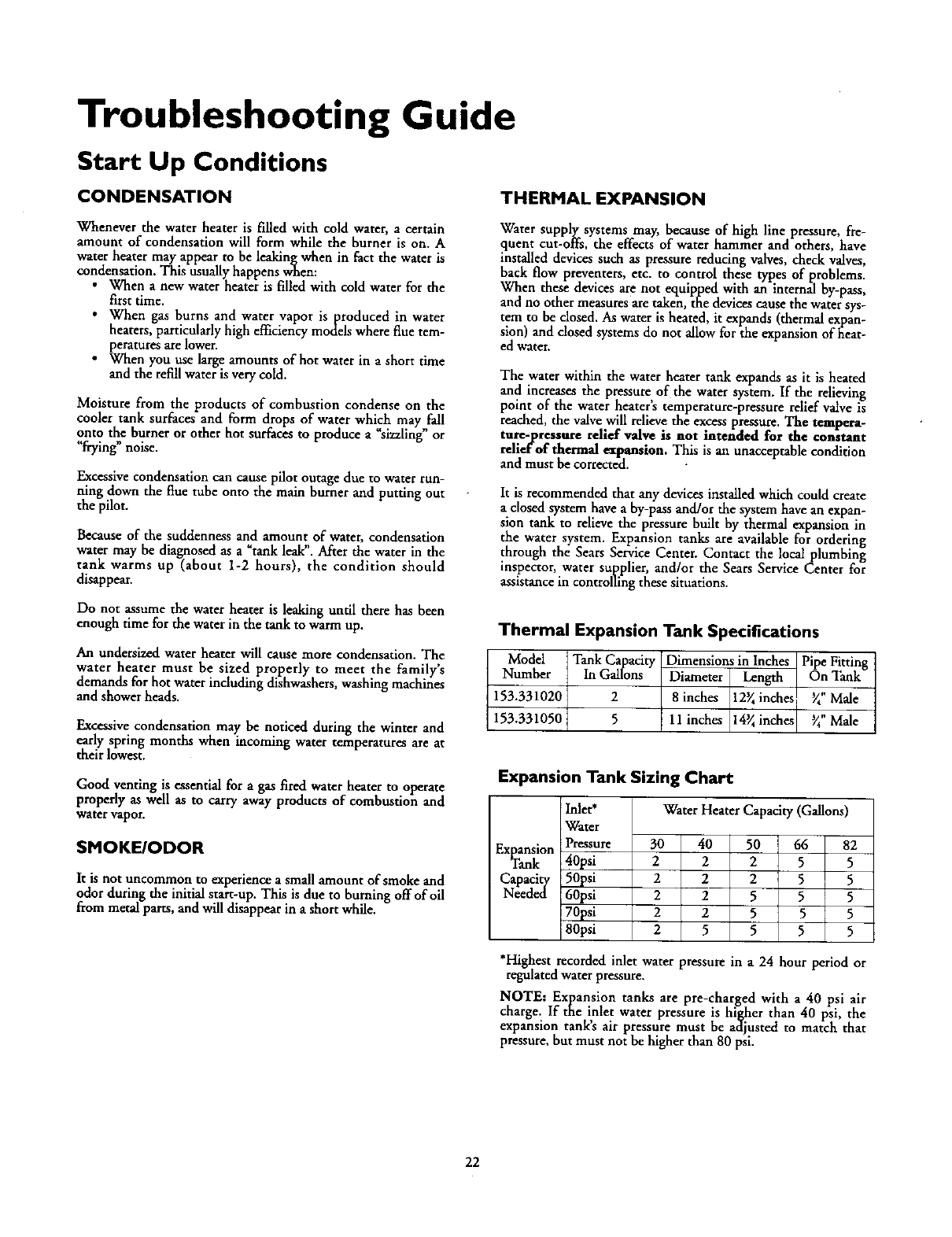
Troubleshooting Guide
Start Up Conditions
CONDENSATION THERMAL EXPANSION
Whenever the water heater is filled with cold water, a certain
amount of condensation will form while the burner is on. A
water heater may appear to be leaklngwhen in fact the water is
condensation. This usually happens when:
• When anew water heater is filled with cold water for the
first time.
• When gas burns and water vapor isproduced in water
heaters, particularly high efficiency models where flue tem-
peratures are lower.
• When you use large amounts of hot water in ashort time
and the refill water is very cold.
Moisture from the products of combustion condense on the
cooler tank surfaces and form drops of water which may fall
onto the burner or other hot surfaces to produce a "sizzling" or
"frying" noise.
Excessive condensation can cause pilot outage due to water run-
ning down the flue tube onto the main burner and putting out
the pilot.
Because of the suddenness and amount of water, condensation
water may be diagnosed as a "tank leak". After the water in the
tank warms up (about 1-2 hours), the condition should
disappear.
Do not assume the water heater is leaking until there has been
enough time for the water in the tank to warm up.
An undersized water heater will cause more condensation. The
water heater must be sized properly to meet the family's
demands for hot water including dishwashers, washing machir_es
and shower heads.
Excessive condensation may be noticed during the winter and
early spring months when incoming water temperatures are at
their lowest.
Good vendng is essential for a gas fired water heater to operate
properly as well as to carry away products of combustiohand
water vapor.
SMOKE/ODOR
It is not uncommon to experience a small amount of smoke and
odor during the initial start-up. This is due to burning off of oil
from metal parts, and will disappear in ashort while.
Water suppl,_, systems may, because of high line pressure, fre-
quent cut-orrs, the effects of water hammer and others, have
installed devices such as pressure reducing valves, check valves,
back flow preventers, etc. to control these types of problems.
When these devices are not equipped with an internal by-pass,
and no other measures are taken, the devices cause the water sys-
tem to be dosed. As water is heated, it expands (thermal expan-
sion) and closed systems do not allow for the expansion of fieat-
ed water.
The water within the water heater tank expands as it is heated
and increases the pressure of the water system. If the relieving
point of the water heater's temperature-pressure relief valve is
reached, the valve will relieve the excess pressure. The tempera-
ture-pressure relief valve is not intended for the constant
relief of thermal e_tpansion. This is an unacceptable condition
and must be corrected.
It is recommended that any devicesinstalledwhich could create
a closedsystem have a by-pass and/or the system havean expan-
sion tank to relieve the pressure built by thermal expansion in
the water system. Expansion tanks are available for ordering
through the Sears Service Center. Contact the local plumbing
inspector, water supplier, and/or the Sears Service Center for
assistancein controlling these situations.
Thermal Expansion Tank Specifications
Model Tank Capacity Dimensions in Inches Pipe Fitting
Number In Gallons Diameter Length On Tank
153.331020 2 8 inches 12_ inches _" Male
153.331050 5 11 inches 14_inches _" Male
Expansion Tank Sizing Chart
Water Heater Capacity (Gallons)
Inlet*
Water
Pressure
40psi
50psi
60psi
70psi
80psi
Expansion 30 40 50 66 82
Tank 2 2 2 5 5
Capacity 2 2 2 5 5
Needed 2 2 5 5 5
2 2 5 5 5
25 5 5 5
*Highest recorded inlet water pressure in a24 hour period or
regulated water pressure.
NOTE: Expansion tanks are pre-charged with a 40 psi air
charge. If the inlet water pressure is higher than 40 psi, the
expansion tank's air pressure must be ac_justed to match that
pressure, but must not be higher than 80 psi.
22
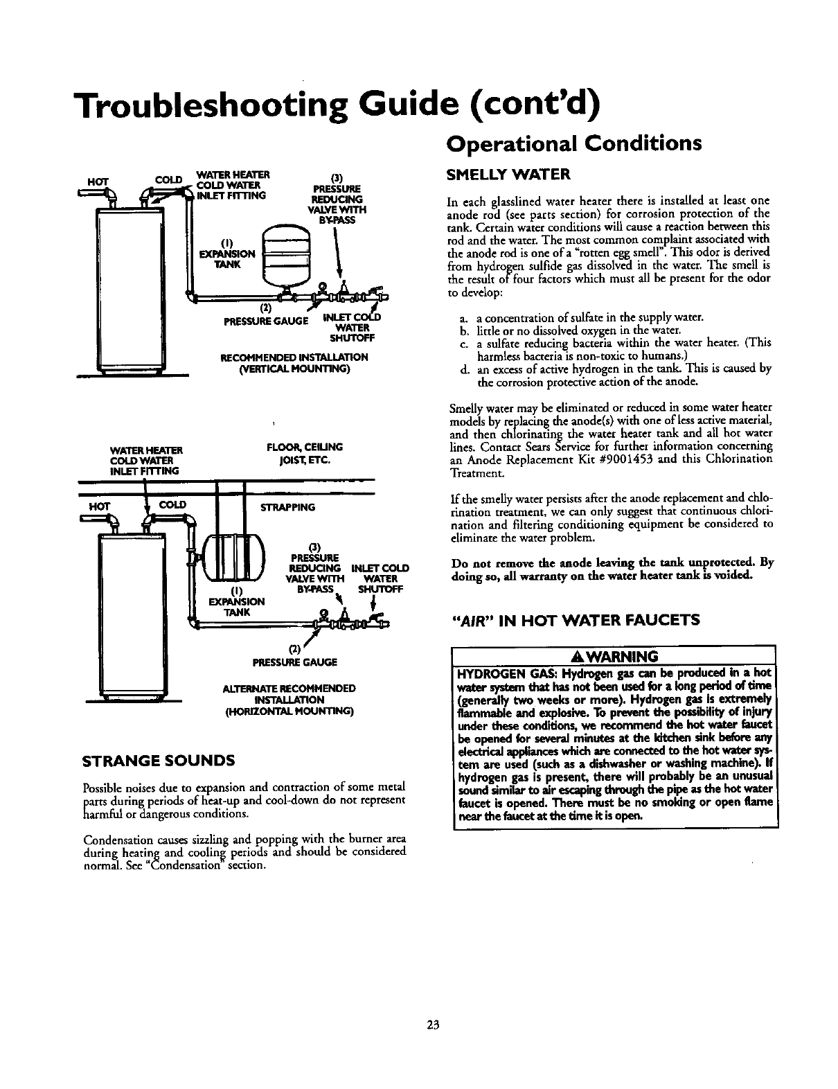
Troubleshooting Guide (cont'd)
Operational Conditions
HOT COLD WATER HEATER O)
COLD WATER PRESSURE
IINLET FITTING REDUCING
VALVEWITH
BY-PASS
WATER
RECOMMENDED INSTALLATION
(VERTICAl. MOUNTING)
SMELLY WATER
In each glasslined water heater there is installed at least one
anode rod (see parts section) for corrosion protection of the
tank. Certain water conditions will cause areaction between this
rod and the water, The most common complaint associated with
the anode rod is one ofa _rotten egg smell". This odor is derived
from hydrogen sulfide gas dissolved in the water. The smell is
the result of four factors which must all be present for the odor
to develop:
a. a concentration of sulfate in the supply water.
b. little or no dissolved oxygen in the water.
c. asulfate reducing bacteria within the water heater. (This
harmless bacteria]s non-toxic to humans.)
d. an excess of active hydrogen in the tank. This is caused by
the corrosion protective action of the anode.
WATER HEATER
COLD WAllER
INLET FR-rlNG
FLOOR, CEIUNG
Jols'¢,ETC.
Smelly water may be eliminated or reduced in some water heater
models by replacing the anode(s) with one of less active material,
and then chlorinating the water heater tank and all hot water
lines. Contact Sears Service for f_rther information concerning
an Anode Replacement Kit #9001453 and this Chlorination
Treatment.
HOT COLD
(I)
EXPANSION
STRAPPING
PRESSURE
REDUCING INLETCOLD
VALVEWITH WATER
BY-PASS SHUTOFF
If the smeUywater persistsafterthe anode replacement and chlo-
rinationtreatment, we can only suggest that continuous chlori-
nation and filtering conditioning equipment be considered to
eliminate the waterproblem.
Do not remove the anode leaving the rank unprotected. By
doing so, all warrantyon the water heater tank is voided.
"AIR" IN HOT WATER FAUCETS
PRESSURE GAUGE
ALTERNATE RECOtttlENDED
INSTAIJ.ATION
(HORIZONTAL MOUNTING)
STRANGE SOUNDS
Possible noises due to expansion and contraction of some metal
parts during periods of heat-up and cool-down do not represent
harmfi_ or dangerous conditions.
Condensation causes sizzling and popping with the burner area
during heating and cootin_ periods and should be considered
normal. See "Condensation section.
AWARNING
I
I HYDROGEN GAS: Hydrogen gas can be produced in ahot
wator systasmthet has not been usedfor alongperind of tin_
(generally two weeks or more). Hydrogen gas is extremely
flammable and explosive.To prevent the possibilityof injury
under these conditions,we recommend the hot water faucet
be opened for severalminutes at the kitchen sinkbefore any
electricalapplianceswhichare connectedto the hot water sy_
tern are used (suchas a dishwasheror washingmachine). If
hydrogen gas is present, there will probably be an unusual
sou_ similarto air ascaping thre_ the pipe es the hot v,am.
faucet is opened. There must be no smoking or open flame
nearthe fancotat the time it is open.
23
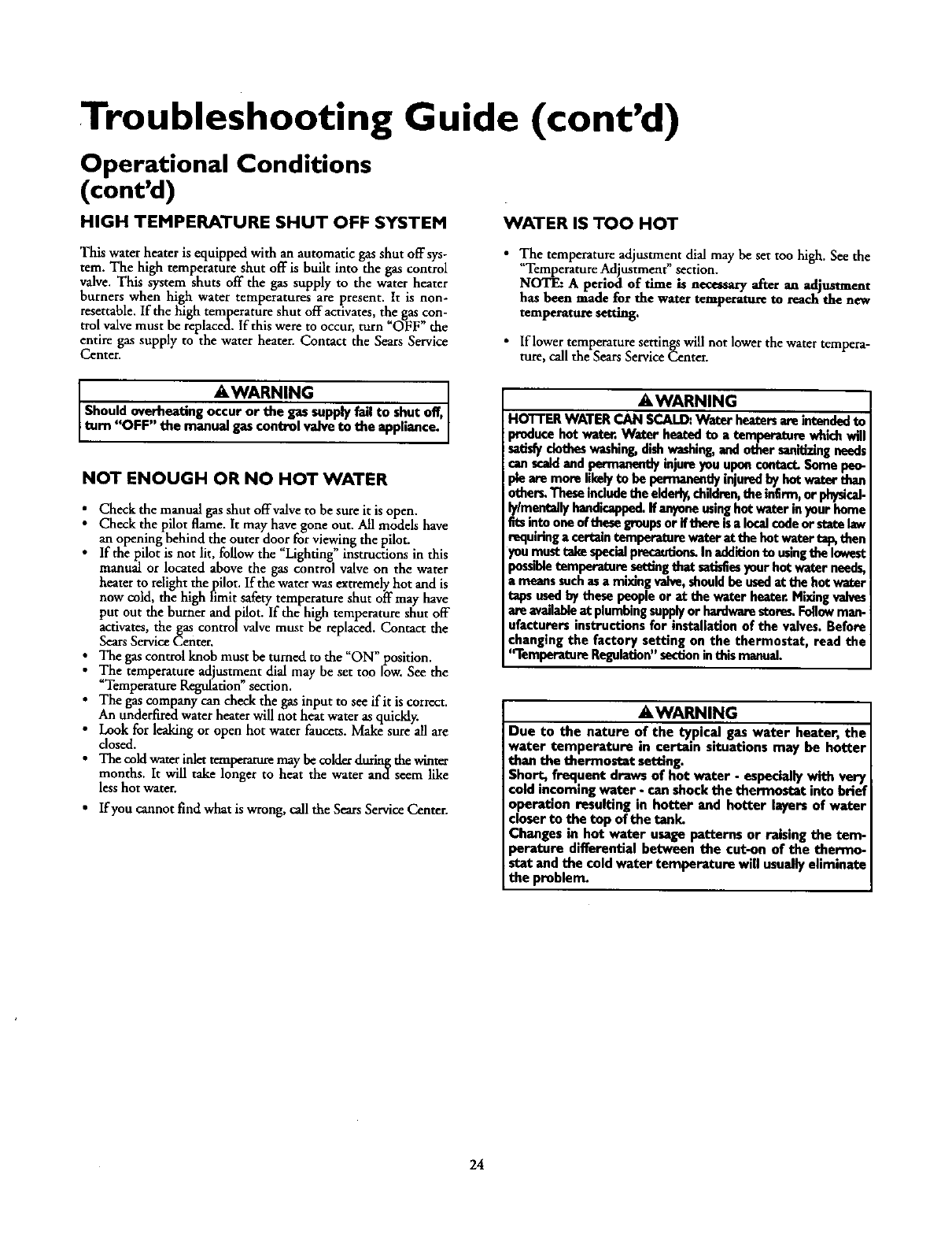
Troubleshooting Guide (cont'd)
Operational Conditions
(cont'd)
HIGH TEMPERATURE SHUT OFF SYSTEM WATER IS TOO HOT
This water heater is equipped with an automatic gas shut offsys-
tern. The high temperature shut off is built into the gas control
valve. This system shuts off the gas supply to the water heater
burners when high water temperatures are present. It is non-
resettable. If the high temperature shut off activates, the gas con-
trol valve must be replaced. If this were to occur, turn "OFF" the
entire gas supply to the water heater. Contact the Sears Service
Center.
•The temperature adjustment dial may be set too high. See the
"Temperature Adjustment" section.
NOTE: A period of time is necessary after an adjustment
has been made for the water temperature to reach the new
temperature setting.
•If lower temperature settings will not lower the water tempera-
ture, call the Sears Service Center.
AWARNING
Shouldoverheadngoccuror the gassupplyfailto shutoff,
tom "OFF" the manualgascontrolvalveto the appliance.
NOT ENOUGH OR NO HOT WATER
i heck the manual gas shut offvalve to be sure it is open.
Check the pilot flame. It may have gone out. All models have
an opening behind the outer door for viewing the pilot.
If the pilot is not lit, follow the "Lighting" instructions in this
manual or located above the gas control valve on the water
heater to relight thepilot. If the water was extremely hot and is
now cold, the high limit safety temperature shut off may have
put out the burner and pilot. If the high temperature shut off
activates, the gas controlvalve must be replaced. Contact the
Sears Service Center.
The gas control knob must be turned to the "ON" position.
The temperature adjustment dial may be set too low. See the
"Temperature Regulation" section.
• The gas company can check the gas input to see if it is correct.
An underfired water heater will not heat water as quickly.
• Look for leaking or open hot water faucets. Make sure all are
closed.
• The cold water inlet temperature may be colder during the winter
months. It will take longer to heat the water and seem like
less hot water.
• If you cannot find what is wrong, call the Sears Service Center.
AWARNING
HOTTER WATER CAN SCALD: Water heatersare intendedto
producehot watt. Water heatedto a temperature whichwill
isut_ clotheswashing,dishwashing,and other sanitizingneeds
canscaldand permanentlyinjureyou uponcontact.Some peo-
ple are more likelyto be permanentlyinjuredby hotwater than
other_ Theseincludethe elderly,children,the inErm, or pl_czi-
ly/mentallyhandicapped.Ifanyoneusinghotwater in yourhome
Etsinto oneof thesegroupsor iftheceisa localcodeorstate law
requiring acertaintemperature waterat the hot waterta_ then
_u musttakespecialprecandou_Inaddition to usingthe lowest
mssibletemperature settingthat sathfiasyour hot water needs,
meanssuchasa mixing valve,shouldbe usedat the hot water
taps usedby these peopleor at the water heater.Mixingvalves
are availableat plumbingsupplyor hardwarestore_ Followman-
ufacturers instructions for installation of the valves. Before
changing the factory setting on the thermostat, read the
'q'emperature Regulation"section inthis manual.
AWARNING
Due to the nature of the typical gas water heater, the
water temperature in certain situations may be hotter
than the thermostat setting.
Short, frequent draws of hot water - especially with very
cold incoming water - can shockthe thermostat into brief
operation multing in hotter and hotter layers of water
closer to the top of the tank.
Changes in hot water usage patterns or raising the tern-
perature differential between the cut-on of the the mlo-
stat and the cold water temperature will usually eliminate
the problem.
24
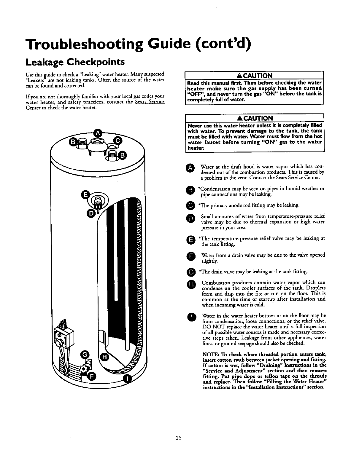
Troubleshooting Guide (cont'd)
Leakage Checkpoints
• * _ . _ ted
Usethis _ulde to checka Leaking water heater•Many suspec
_Lcakers are not leaking tanks. Often the source of the water
can be found and corrected.
If you are not thoroughly familiar with your local gascodes your
water heater, and safety practices, contact the
to check the waterheater.
ACAUTION
Read this manual first. Then before checking the water
heater make sure the gas supply has been turned
"OFF", and never turn the gas "ON" before the tank Is
Lcomp etely fo of water.
&CAUTION
Never usethis water heater unlessit is completelyfilled
with water. To prevent damage to the tank, the tank
must be Iilledwith water,Water must flow from the hot
water faucet before turning "ON" gas to the water
heater.
O Water at the draft hood is water vapor which has con-
densedout of the combustion products. This is causedby
a problem in the vent. Contact the SearsServiceCenter.
O*Condensationmay be seen on pipesin humid weather or
pipe connections may be leaking.
Q'The primary anode rod fitting may be leaking.
O Small amounts of waterfrom temperature-pressure relief
valve may be due to thermal expansion or high water
pressurein your area.
O'The temperature-pressure relief valve may be leaking at
the tank fitting.
Q Water from adrain valve may be due to the valve opened
slightly.
Q'The drain valve may be leaking at the tank fitting.
O Combustion products contain water vapor which can
condense on the cooler surfaces of the tank. Droplets
form and drip into the fire or run on the floor. This is
common at the time of startup after installation and
when incoming wateris cold.
O Water in the water heater bottom or on the floor may be
from condensation, loose connections, or the reliefvalve.
DO NOT replacethe water heater until a full inspection
of all possible water sources is madeand necessarycorrec-
tive steps taken. Leakagefrom other appliances, water
lines, or groundseepageshould also be checked.
NOTE: To check where threaded portion enters tank,
insert cotton swab between jacket opening and fitting.
If cotton is wet, follow "Draining' instructions in the
"Service and Adjustment" section and then remove
fitting. Put pipe dope or teflon tape on the threads
and replace. Then follow =Filling the Water Heater"
instructions in the "Installation Instructions" section.
25
Warranty
About Your Warranty
THE PRICE OF YOUR WATER HEATER DOES NOT INCLUDE
A FREE CHECKUP SERVICECALL. On Water Heater Instalhtions
Arranged BySears,Searswarrants the installation.
ON INSTALLATIONS NOT MADE BY SEARS AUTHORIZED
CONTRACTORS:
1.Your Searswarranty appliesto the product only.
2. Sears does not warrant the installation.
3. A charge will be made on service calls due to poor or incomplete
imtallation. These include:
a. Adjusting thermostat
b. Lightingpilot
c. Leaksin pipes or fittings
d. Improper venting
e. Condensation
Thismanualis in non-technicallanguage.It may help you,avoidthe
cost ofa needlemservicecall.Manyservicecallsreallyarentneeded.
Suchaswhen:
1.Thegasisturned"OFF".
2. Thepilot isout.
3.A gasor waterleakisdueto loosepipeor connections.
FULL ONE YEARWARRANTY ON WATER HEATER
Forone year from the date of purchase, when your Sears Kenmore water heater is installed and operated in a single-family
residencein accordancewith the instructions in this manual, Searswill:
1. Repair defects in material or workmanship in this waterheater, free of chaxge.
2. Furnish and installa new current model water heater of equal capacityand quality, freeof charge, ifa leakoccursin the
tank.
LIMITED WARRANTY ON TANKS THAT LEAK
After one year and through 5years from the date of purchase for water heaters used in a single-family residence, ifa leak
occurs in the tank, Sears will furnish anew current model water heater of equal capacity and quality. You will be charged
for any installation.
If the water heater is subjected to commercial, institutional, industrial or use in residences of two families or more, the
above warranty coverage for tanks that leak is effective for 2 years from the date of purchase.
To obtain warranty service, SIMPLY CALL 1-800-4MY-HOME (1-800-469-4663). =This warranty applies only while this
product is in use in the United States."
This warranty givesyou specificlegal rights and you may also have otherrights which vary from state to state.
SEARS, ROEBUCK AND CO., Dept. 817 WA, HOFFMAN ESTATES, IL 60179
Sears Installation Warranty
In addition to any warranty extended to you on the Sears merchandise
involved,which warranty becomes effectivethe date the merchandise is
installedshould the workmanship of anySears arrangedinstalhtion prove
faultywithin oneyear,Searswill,upon notice fromyou, causesuch faultsto
be correctedat no additional costto you. If youwant this heaterprofession-
allyinstalledbySearscontact your SearsSalesperson.They will arrangefor
prompt, qualityinstalhtion.
Sears Installation Policy
Allinstallationlabor arranged bySearsshall be performed in a neat,work-
manlike manner in accordancewith generally accepted trade practices.
Further, all installationsshall comply with all local laws,codes regulations
and ordinances.The customer shall also be protected, during installation,
by insurance relating to property damage, Worker's Compensation and
PublicLiability.
If you want this water heater professionallyinstalled by Searscontact your
Salesperson.They will arrangefor prompt, quality installation by Sears
authorizedcontractors.
ForIn-homemajorbrandrepairservice
Call24hoursaday,7daysaweek
1-800-4-MY-HOME
(1-800-4S_F._03)
The modelnumberof yourwaterheaterisfound onthe modelratingplateon the frontof the waterheater.
Sears, Roebuck and Co., Hoffman Estates, IL 60 179 U.S.A. 00029,s ,
