Kenmore 36272296790 User Manual GAS RANGE Manuals And Guides L0707056
KENMORE Free Standing, Gas Manual L0707056 KENMORE Free Standing, Gas Owner's Manual, KENMORE Free Standing, Gas installation guides
User Manual: Kenmore 36272296790 36272296790 KENMORE GAS RANGE - Manuals and Guides View the owners manual for your KENMORE GAS RANGE #36272296790. Home:Kitchen Appliance Parts:Kenmore Parts:Kenmore GAS RANGE Manual
Open the PDF directly: View PDF ![]() .
.
Page Count: 6
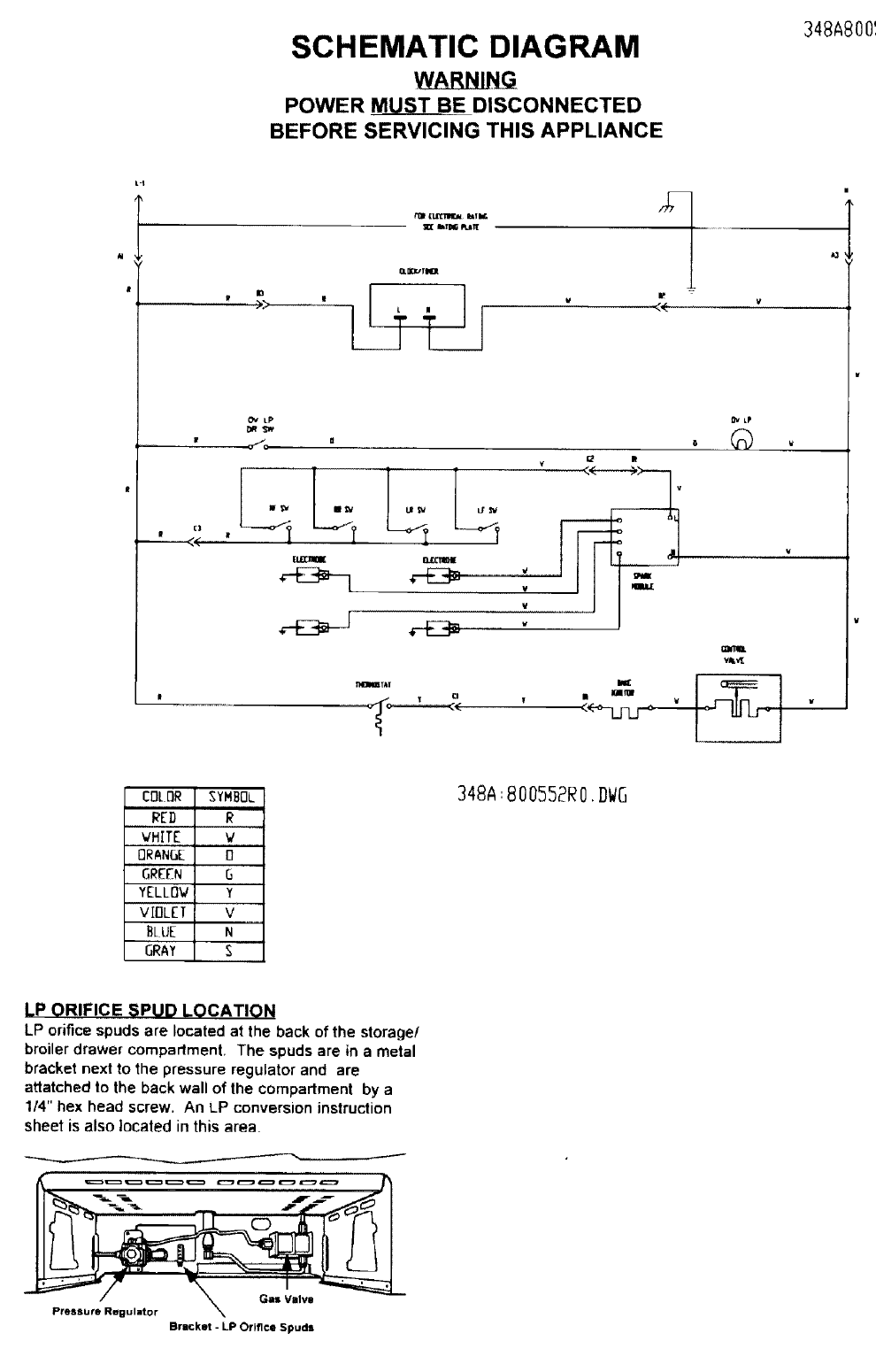
SCHEMATIC DIAGRAM
_NLNG
POWER M__MU_S_T_BEDISC ON NEC T ED
BEFORE SERVICING THIS APPLIANCE
348A800_
Io
It II
,),>
,M1
OLDOUTJ_I
LP
af_'d lena Lg%v Lfr_
[I,10_ _lllltlll[
v _ m
v
w
w
9v LP
°®
-__VL.r--_ ,
COLOR SYMBOL
RED R
VHITE v
ORANGE 0
GREEN O
YELLOV Y
VIOLET V
BLUE N
GRAY S
348A: 800552R0. DWG
LP ORIFICE SPUD LOCATION
LP orifice spuds are located at the back of the storage/
broiler drawer compadment, The spuds are in a metal
bracket next to the pressure regulator and are
attatched to the back wall of the compartment by a
1/4" hex head screw. An LP conversion instruction
sheet is also located in this area
Gain Valve
Pressure Regulator
Bracket -LP Orifice Spuds
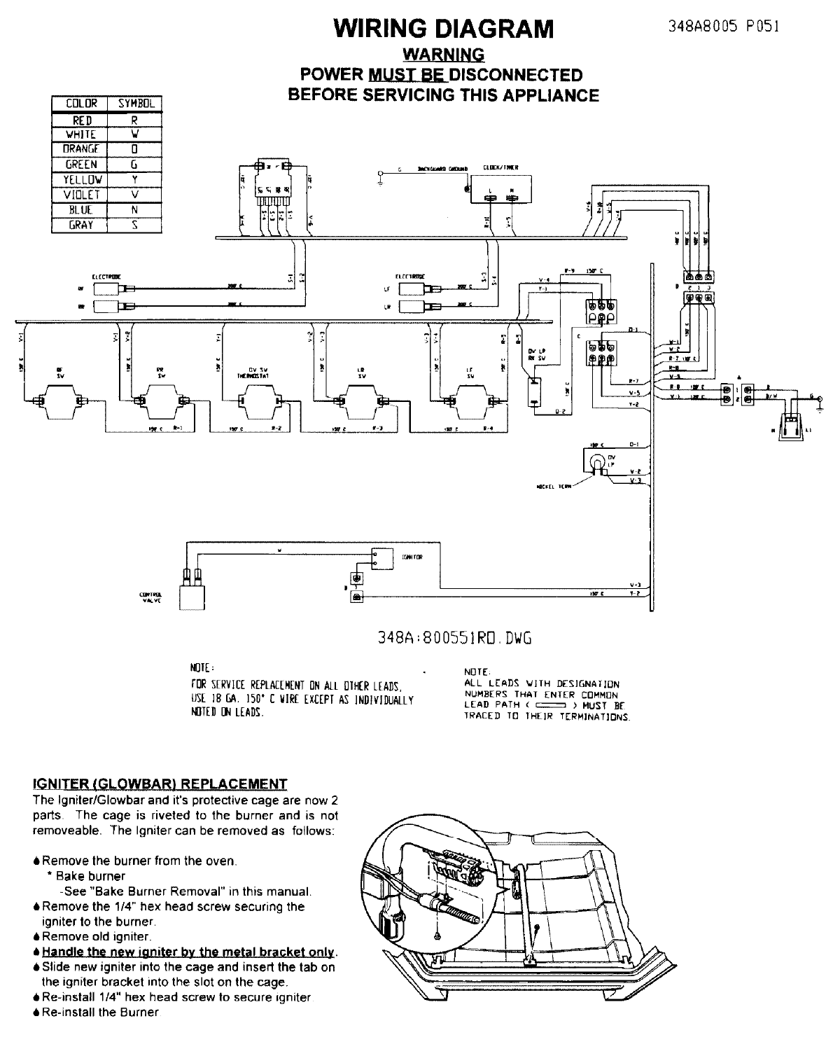
WIRING DIAGRAM
WARNING
POWER MU.$_T_B_D ISC O NN ECTE D
BEFORE SERVICING THIS APPLIANCE
348A8005 PO5I
RED R
WHITE V
ORANG[ 0
GE"['N G .....
YELLDV Y
VIOLET V
BLUE N
GRAY S
[LECxIW(
v_v[
w)
348A ',800551RO, DWG
NUIE:
FOR SERVICEREPLACEMENTON ALL OIHER LEADS,
USE ]BGA. 150'C VIE EXCEPIAS INDIVIDUALLY
NOIED DN LEADS.
NOTE_
ALL LEAD_ VITH DESIGNAIION
NUMBERS THAI ENTER COMMON
LEAD PATH ( _ )MUST BE
TRACED To IHE]R TERMINATIONS.
IGNITER (GLOWBAR} REPLACEMENT
The Igniter/Glowbar and it's protective cage are now 2
parts The cage is riveted to the burner and is not
removeable The Igniter can be removed as follows:
_Remove the burner from the oven,
*Bake burner
-See "Bake Burner Removal" in this manual,
6Remove the 1/4" hex head screw securing the
igniter to the burner.
iRernove old igniter.
_Handle the new igniter by the metal bracket only.
6Slide new igniter into the cage and insert the tab on
the igniter bracket into the slot on the cage.
4Re-install 1/4" hex head screw to secure igniter
6 Re-install the Burner
Burner
LF,LR 1_44mm
RF 1.65 mm
WB19KS066
.84 mm WB28K0022
TO RAISE OR REMOVE COOKTOp
Remove burner caps and heads
6Disengage 2 front clips using a flat biaded screw
driver as shown below
0Lift top up at front.
FOR REMOVAL:
8Disconnect electrode leads.
6 Disengage prop rods from range side panels
6 Lower top approximately 1/2 way down
6 Shift top left or right to disengage hinge pros at rear.
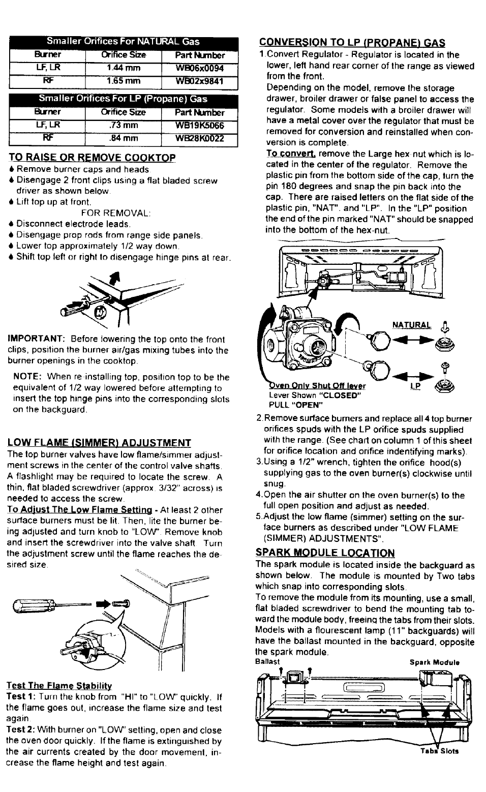
CONVERSION TO LP (PROPANE) GAS
1Convert Regulator - ReguJator is located in the
lower, left hand rear corner of the range as viewed
from the front.
Depending on the model, remove Ibe storage
drawer, broiler drawer or false panel to access the
regulator. Some models with abroiler drawer will
have a metal cover over the regulator that must be
removed for conversion and reinstalled when con-
version is complete.
T_ remove the Large hex nut which is lo-
cated in the center of the regulator. Remove the
plastic pin from the bottom side of the cap, turn the
pin 180 degrees and snap the pin back into the
cap. There are raised letlers on the flat side of the
plastic pin, "NAT". and "LP". In the "LP" position
the end of the pin marked "NAT" should be snapped
into the bottom of the hex-nut.
IMPORTANT: Before lowering the top onto the front
clips, position the burner air/gas mixing tubes into the
burner openings in the cooktop.
NOTE: When re installing top, position top to be the
equivalent of 1/2 way lowered before attempting to
insert the top hinge pins into the corresponding slots
on the backguard
LOW FLAME ISIMMER) ADJUSTMENT
The top burner valves have low flamefsimrner adjust-
ment screws in the center of the control valve shafts.
A flashlight may be required to locate the screw. A
thin, flat bladed screwdriver (approx 3/32" across) =s
needed to access the screw
To Adjust The Low Flame Settino - At least 2 other
surface burners must be lit. Then, latethe burner be
ing adjusted and turn knob to "LOW" Remove knob
and insert the screwdriver into the valve shaft Turn
the adjustment screw until the flame reaches the de
sired size,
Test The Flame Stability
Test 1: Turn the knob from "HI" to "LOW" quickly. If
the flame goes out, increase the flame size and test
again
Test 2: With burner on "LOW" setting, open and close
the oven door quickly. Ifthe flame is extinguished by
the air currents created by the door movemenl, in-
crease the flame height and test again.
Lever Shown"CLOSED"
PULL"OPEN"
2. Remove surface burners and replace all 4 top burner
orifices spuds with the LP orifice spuds supplied
with the range. (See chart on column 1 of this sheet
for orifice location and orifice indentifying marks).
3.Using a 1/2" wrench, tighten the orifice hood(s)
supplying gas to the oven burner(s) clockwise until
snug.
4.Open the air shutter on the oven burner(s) to the
full open position and adjust as needed.
5.Adjust the low flame (simmer) setting on the sur-
face burners as described under "LOW FLAME
(SIMMER) ADJUSTMENTS".
SPARK MODULE LOCATION
The spark module is located inside the backguard as
shown below. The module is mounted by Two tabs
which snap into corresponding slots
To remove the module from its mounting, use a small,
flat bladed screwdriver to bend the mounting tab to-
ward the module body, freeincl the tabs from their slots.
Models with a flourescent lamp (11" backguards) will
have the ballast mounted in the backguard, opposite
the spark module.
Ballast Spark Module
Slots
I! IMPORTANT SAFETY
NOTICE
THIS INFORMATION IS INTENDED FOR USE BY INDIVIDU-
LS POSSESSING ADEQUATE BACKGROUNDS OF ELEC-
RICAL, ELECTRONIC AND MECHANICAL EXPREIENCE,
NY ATTEMPT TO REPAIR A MAJOR APPLIANCE MAY
RESULT IN PERSONAL INJURY AND PROPERTY DAMAGE
THE MANUAFACTURER OF SELLER CANNOT BE RESPON-
SIBLE FOR THE INTERPRETATION OF THIS INFROMATION,
NOR CAN IT ASSUME ANY LIABILITY IN CONNECTION
WITH ITS USE.
DISCONNECT POWER BEFORE SERVICING
IMPORTANT -RECONNECT ALL
GROUNDING DEVICES,
ALL PARTS OF THIS APPLIANCE CAPABLE OF CONDUCT*
rNG ELECTRICAL CURRENT ARE GROUNDED. IF GROUND-
ING WIRES, SCREWS, STRAPS, NUTS OR WASHERS USED
1"O COMPLETE A PATH TO GROUND ARE REMOVED FOR
SERVICE, THEY MUST BE RETURNED TO THEIR ORIGINAL
POSITION AND PROPERLY FASTENED.
Burner Output Rating:BTU/HR
16,000
Ben_,orleTS5Nmt_tOarl,_,zeop,n,nQ
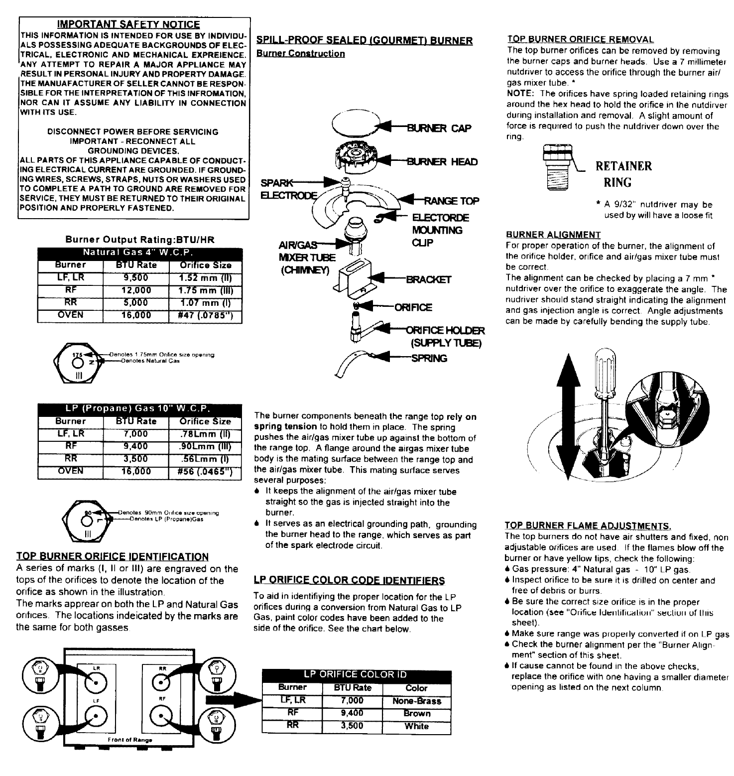
SPILL-PROOF SEALED/GOURMET) BURNER
Burner Construction
CAP
HEAD
AIR/_ CLIP
(C MNEY)
I'_I_ORIRCE
_Ii'Of_RCE HOLDER
TOP BURNER ORIFICE REMOVAL
The top burner orifices can be removed by removing
the burner caps and burner heads. Use a 7 millimeter
nutdnver to access the orifice through the burner air/
gas mixer tube, *
NOTE: ]he orifices have spring loaded retaining rings
around the hex head to hold the orifice in the nutdirver
during installation and removal. A slight amount of
force is required to push the nutdriver down over the
ring.
RETAINER
RING
*A 9/32" nuldriver may be
used by will have aloose fit
B RN_L___._R_L[_ N M ENT
For proper operation of the burner, the alignment of
the orifice holder, orifice and air/gas mixer tube must
be correct.
The alignment can be checked by placing a 7 mm *
nutdriver over the orifice to exaggerate the angle. The
nudriver should stand straight indicating the alignment
and gas injection angle is correct. Angle adjustments
can be made by carefully bending the supply tube.
TOP BURNER ORIFICE IDENTIFICATION
Aseries of marks (I, II or III) are engraved on the
tops of the orifices to denote the location of the
orifice as shown in the illustration,
The marks apprear on both the LP and Natural Gas
onfices. The locations indeicated by the marks are
the same for both gasses
The burner components beneath the range top rely on
spring tension to hold them in place The spring
pushes the air/gas mixer tube up against the bottom of
the range top. A flange around the airgas mixer tube
body is the mating surface between the range top and
the air/gas mixer tube, This mating surface serves
several purposes:
•It keeps the alignment of the air/gas mixer tube
straight so the gas is injected straight into the
burner.
6It serves as an electrical grounding path, grounding
the burner head to the range, which serves as part
of the spark electrode circuit,
LP ORIFICE COLOR CODE IDENTIFIER_
To aid in identifiying the proper location for the LP
orifices durinq a conversion from Natural Gas to LP
Gas, paint color codes have been added to the
side of the orifice. See the chart below,
White
{
\
TOP BURNER FLAME ADJUSTMF_NJ$.
The top burners do not have air shutters and fixed, non
adjustable orifices are used. if the flames blow off the
burner or have yellow tips, check the following:
6Gas pressure: 4" Natural gas -10" LP gas.
Inspect orifice to be sure it is drilled on center and
free of debris or burrs.
IBe sure the correct size orifice is in the proper
location (see "Orifice Iduiflil_ualiuH" SeL:tiUll or IIIis
sheet).
• Make sure range was p[operly converted if on LP gas
• Check the burner alignment per the "Burner Align
merit" section of this sheet.
ill If cause cannot be found in the above checks,
replace the orifice with one having a smaller diameter
opening as listed on the next column
OVEN TEMPERATURE CALIBRATION
NOTE: Calibration adjustments are made by mov-
ing the knob skirt. DO NOT make any adjustments
to the thermostat itself.
IMPORTANT: Before making any temperature
adjustments, be sure the oven thermostat capil-
lary bulb is properly positioned in the bulb
mounting clips, If capillary bulb is out of position
and contacts oven wall, calibration will be incor-
rect. An unusually dirty capillary bulb will also
affect thermostat calibration,
TO ADJUST KNOB:
(As covered in the Use and Care Manual)
Note position of pointer to screw
before adjuzlrnent
Hotter Cooler
1, Loosen screws.
2. Hold knob skirt and move knob so that the top
screw (nearest arrow) moves to HOTTER to in-
crease tempeature or COOLER to decrease tem-
perature, each notch or "click" is 10 degree
change, Maximum change from factory setting
is ±50 degrees.
THERMOSTAT REPLACEMENT
1. Remove power from range,
2. Pull range away from wall.
3. Remove cooktop and manifold panel as de
scribed on this sheet.
4. Release thermostat bulb from clips inside oven
cavity.
5. Feed capillary and bulb through hole in top
of oven cavity,
6. From rear of range, pull the capillary and bulb
out the back of the range through one of the vent
openings beneath the control panel. It will be
necessary to bend the bulb to accomplish the
above.
7, Feed the capillary and bulb back through the vent
opening and into the opening leading to the
burner box.
8. Remove the wiring from the thermostat and re-
move the _erews eeeuring thermostat to man;-
fold.
Install replacement thermostat in reverse order. Be
sure thermostat bulb does not touch rear wall of
cavity once mounted in the mounting clips,
Also, the capillary tube must not be in contact with
the oven flue or any other source of extreme heat,
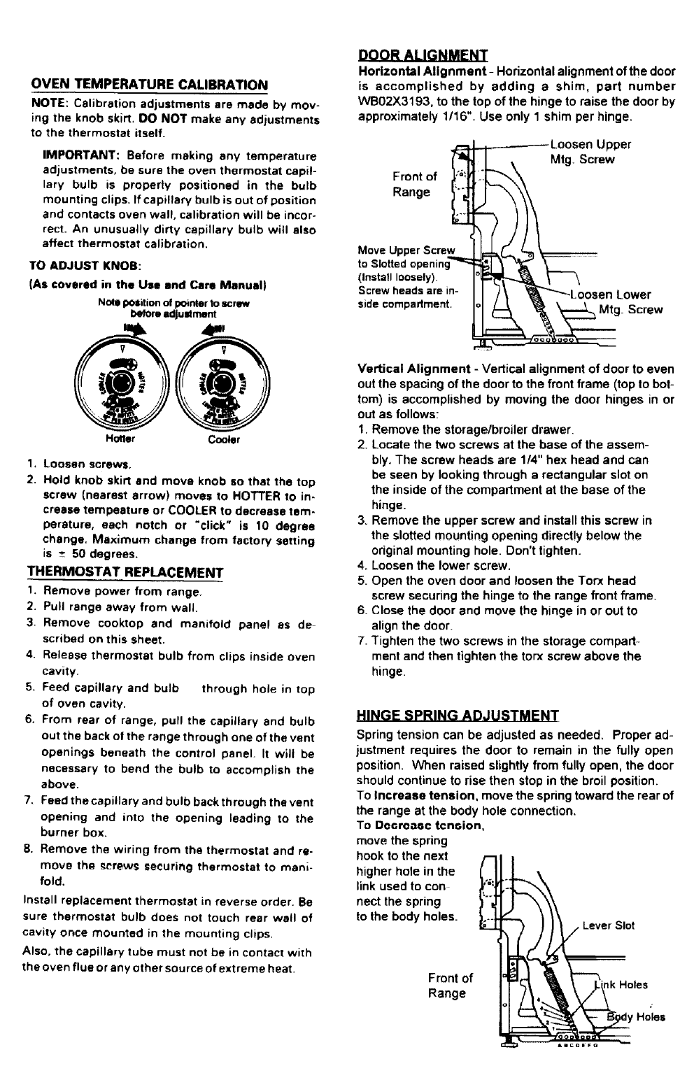
Horizontal Alignment - Horizontal alignment of the door
is accomplished by adding a shim, part number
WB02X3193. to the top of the hinge to raise the door by
approximately 1/16". Use only 1 shim per hinge.
Front of
Range _
tMoC;l: ttUpp: peSnCinre_._
<S:rSt:wI'_::sd_ly) min. l"l
side compadment _
_'_'_Loosen Lower
0sc.ew
Vertical Alignment - Vertical alignment of door to even
out the spacing of the door to the front frame (top to bot-
tom) is accomplished by moving the door hinges in or
out as follows:
1, Remove the storagelbroiler drawer.
2. Locate the two screws at the base of the assem-
bly. The screw heads are 1/4" hex head and can
be seen by looking through a rectangular slot on
the inside of the compartment at the base of the
hinge.
3. Remove the upper screw and install this screw in
the slotted mounting opening directly below the
original mounting hole. Don't tighten.
4. Loosen the lower screw.
5. Open the oven door and loosen the Torx head
screw securing the hinge to the range front frame.
6. Close the door and move the hinge in or out to
align the door
7Tighten the two screws in the storage compad-
ment and then tighten the torx screw above the
hinge
HINGE SPRING ADJUSTMENT
Spring tension can be adjusted as needed. Proper ad-
justment requires the door to remain in the fully open
position, When raised slightly from fully open, the door
should continue to rise then stop in the broil position.
To increase tension, move the spring toward the rear of
the range at the body hole connection,
To Docroaoc tcnoion,
move the spring
hook to the next
higher hole in the
link used to con
nect the spring
to the body holes.
Front of tk Holes
Range
Holes
GAS, FREESTANDING RANGE
WITH SPILL-PROOF BURNERS
OVEN BURNER
1. Oven Burner Gas Shut-off- Attached to the range
gas pressure regulator is ashut-off valve which
shuts off gas to the oven only.
Check the position of the shut-off valve first when
diagnosing a "no oven" condition,
(See illustration under "Conversion to LPGes').
2, Burner Ignition System - The ov_n burner is ig-
nited by a glow-bar ignition system,
The ignition system consists of the thermostat,
the ignitor and the oven safety valve (gas valve),
The three components are wired in a series cir-
cuit.
The most important points to know about the
ignition system is THE IGNITOR RESISTANCE
DECREASES AS THE IGNITOR SURFACE TEM-
PERATURE INCREASES and THE SAFETY VALVE
OPERATES BY CURRENT, NOT VOLTAGE.
From a cold start, the ignitor needs 30 to 60 se-
conds, with voltage applied, to reduce its electri-
cal resistance enough to provide a minimum of
2.5 Amps current flow in the series circuit. This
is the required current flow needed for the safety
valve to open to supply gas to the burner. With
25 to 3.0 Amps flowing in the circuit, the ignitor
temperature is between 1800 to 2500°F.
The ignitor will remain energized at all times dur
ing burner operation.
if ignitor glows red but circuit does not draw at
least 2.5 Amps, the fault is usually with the ig-
nitor, not the valve. (Be sure the oven burner gas
shut-off is open),
LOLOWaAR IGNITION CIRCUIT N
.GLOW EAR OVEN
TsrAT _.rrE. VALVe
IMPORTANT -Do not place 120 volts directly across
the safety valve when testing. The resulting current
through the valve would destroy the internal heater
circuit.
NOTE: An open gas valve heater circuit usually in-
dicates exccessive current flow in the ignition cir-
cuit, Replacement of the ignitor and valve is recom-
mended.
OVEN BURNER ADJUSTMENTS
The oven burner is equipped with an air shutter and
au.ivu_sal (NAT or LP) orifice hood and orifice nee-
dle.
1, Air Shutter Adjustment
A. Remove oven door, oven bottom, broiler
drawer and oven valve shield.
B. Remove flame spreader from top of burner.
C. Turn thermostat to any BAKE temperature,
observe flame:
• Soft, yellow flames indicate too little pri-
mary air - open air shutter more. If condi_
tion cannot be corrected with air shutter
wide open. see Flame Size.
• Harsh, blowing flames indicate too much
air, Reduce air shutter opening.
Pub. No, 31-20127 (_
164D2773P069
Screw _Air Shutter
2. Flame size - The inner, blue cone of the burner
flame should be between '/2 to 3/, inches in length
with little Or no yellow tipping (observed with
flame spreader removed.)
1/=- to =/4"P_INNER CONE
,/ OF FLAME
/'I/"_[_ OVEN/BROILER
Flame Size Reduction -If air shutter adjust-
ments fail to provide proper flame length or
flame characteristics, the gas flow to the
burner can be reduced (on Natural Gas instal-
lations only) by turning the orifice hood
slightly in the LP direction. For best results,
remove the flame spreader and observe the
flame while turning the hood,
BACKGUARD DISSASSEMBLY
MODELS WITH FLUORESCENT
WORK LIGHTS
1. Lift front edge of light cover and rotate cover
upward to the fully open position.
2. Remove fluorescent tube (lift tube out without
rotating).
ALL MODELS
3. Remove the 2front mounting screws (#15 torx)
as shown.
4 Gently, pull panel out at bottom and rotate panel
upward.
5. Push panel back at top, freeing panel mounting
tabs from top of backguard frame.
• TECHNICAL DATA SHEET ,,
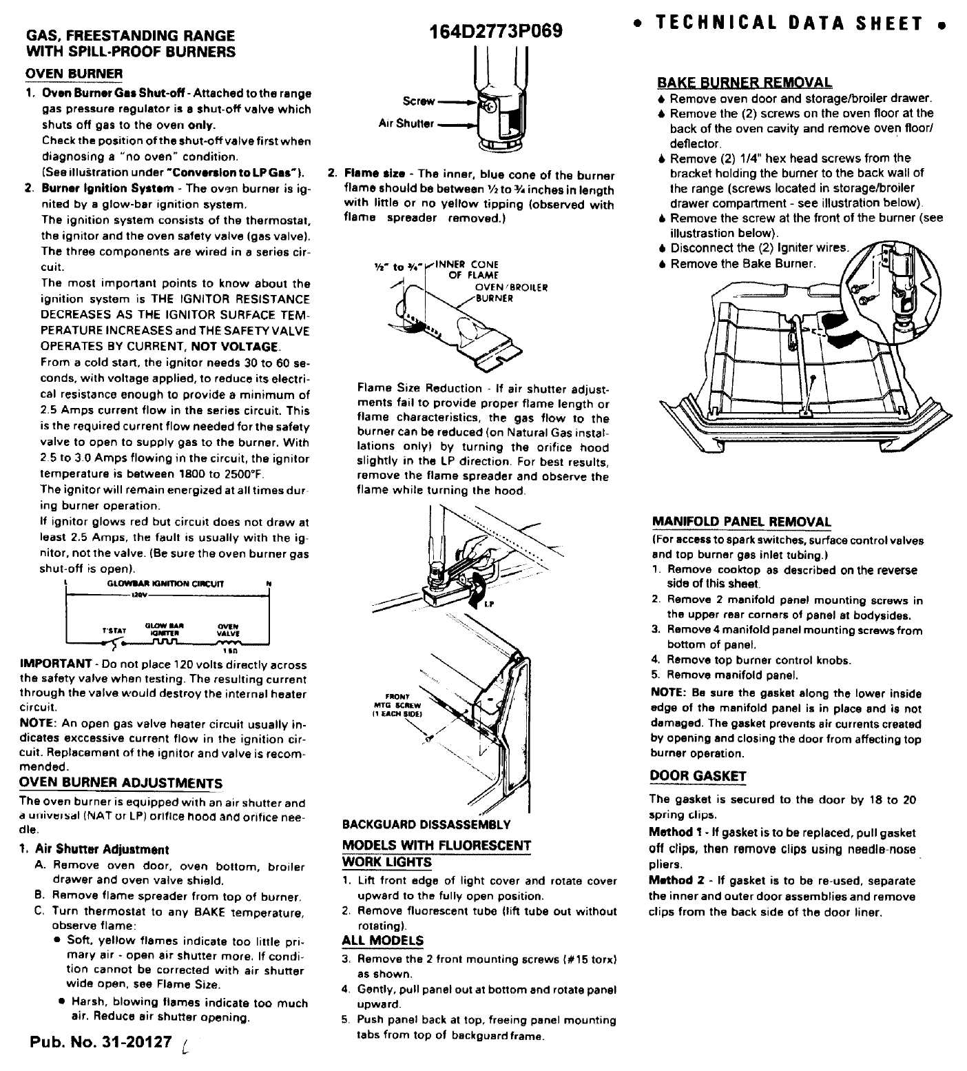
BAKE BURNER REMOVAL
•Remove oven door and storage/broiler drawer.
•Remove the (2) screws on the oven floor at the
back of the oven cavity and remove oven floor/
deflector.
6 Remove (2) 114" hex head screws from the
bracket holding the burner to the back wall of
the range (screws located in storage/broiler
drawer compa_ment -see illustration below)
•Remove the screw at the front of the burner (see
illustrastion below).
6 Disconnect the (2) Igniter wires.
MANIFOLD PANEL REMOVAL
(For access to spark switches, surface control valves
and top burner gas inlet tubing.)
1. Remove cool<top as described on the reverse
side of this sheet
2. Remove 2 manifold panel mounting screws in
the upper rear corners of panel at bodysidas.
3. Remove 4 manifold panel mounting screws from
bottom of panel,
4. Remove top burner control knobs.
5. Remove manifold panel.
NOTE: Be sure the gasket along the lower inside
edge of the manifold panel is in place and is not
damaged. The gasket prevents air currents created
by opening and closing the door from affecting top
burner operation.
DOOR GASKET
The gasket is secured to the door by 18 to 20
spring clips,
Method I - If gasket is to be replaced, pull gasket
Off clips, then remove clips using needle-nose
pliers.
Method 2 - If gasket is to be re-used, separate
the inner and outer door assemblies and remove
clips from the back side of the door liner.
