Kenmore 625349225 User Manual IRON FILTER Manuals And Guides L0911230
KENMORE Iron Filter Manual L0911230 KENMORE Iron Filter Owner's Manual, KENMORE Iron Filter installation guides
User Manual: Kenmore 625349225 625349225 KENMORE IRON FILTER - Manuals and Guides View the owners manual for your KENMORE IRON FILTER #625349225. Home:Plumbing Parts:Kenmore Parts:Kenmore IRON FILTER Manual
Open the PDF directly: View PDF ![]() .
.
Page Count: 32
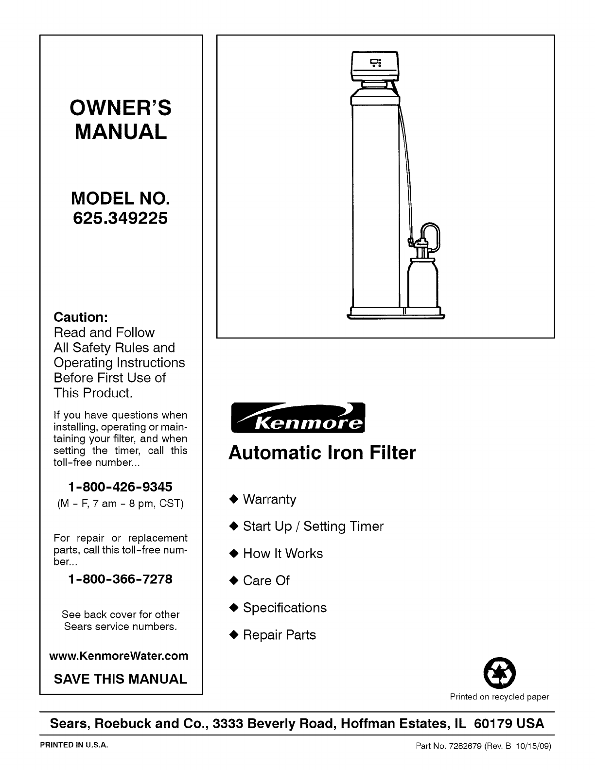
OWNER'S
MANUAL
MODEL NO.
625.349225
Caution:
Read and Follow
All Safety Rules and
Operating Instructions
Before First Use of
This Product.
If you have questions when
installing, operating or main-
taining your filter, and when
setting the timer, call this
toll-free number...
1-800-426-9345
(M-F, 7am-8pm, CST)
For repair or replacement
parts, call this toll-free num-
ber...
1-800-366-7278
See back cover for other
Sears service numbers.
www.KenmoreWater.com
SAVE THIS MANUAL
Automatic Iron Filter
• Warranty
• Start Up /Setting Timer
• How It Works
• Care Of
• Specifications
• Repair Parts
Printed on recycled paper
Sears, Roebuck and Co., 3333 Beverly Road, Hoffman Estates, IL 60179 USA
PRINTED IN U,S,A. Part No. 7282679 (Rev. B 10/15/09)
W
A
R
R
A
N
T
Y
SEARS RESIDENTIAL WATER FILTER
FULL ONE YEAR WARRANTY ON FILTER
For one year from the date of purchase, when this filter is installed and maintained
in accordance with our instructions, Sears will repair, free of charge, defects in
material or workmanship in this water softener.
FULL FIVE YEAR WARRANTY AGAINST LEAKS
For five years from the date of purchase, Sears will furnish and install a new current
model water filter tank, free of charge, if the tank develops a leak.
TO OBTAIN WARRANTY SERVICE, SIMPLY CONTACT THE NEAREST SEARS
SERVICE CENTER THROUGHOUT THE UNITED STATES. This warranty
applies only while this product is in use in the United States.
This warranty gives you specific legal rights, and you may have other rights which
vary from state to state.
Sears, Roebuck and Co., D/817 WA, Hoffman Estates, IL 60179
If you want your water filter professionally installed, talk to your Sears Salesman. He will arrange for a
prompt, quality installation by Sears Authorized installers.
SEARS INSTALLATION POLICY SEARS INSTALLATION WARRANTY
All installation labor arranged by Sears shall be per-
formed in a neat, workmanlike manner in accor-
dance with generally accepted trade practices. Fur-
ther, all installations shall comply with all local laws,
codes, regulations and ordinances. Customer shall
also be protected, during installation, by insurance
relating to Property Damage, Workman's Com-
pensation and Public Liability.
In addition to any warranty extended to you on the
Sears merchandise involved, which warranty be-
comes effective the date the merchandise is
installed, should the workmanship of any Sears ar-
ranged installation prove faulty within one year,
Sears will, upon notice from you, cause such faults
to be corrected at no additional cost to you.
FACTS AND FIGURES TO KEEP
Fill in the blanks below and keep this book in a safe place so you always have
these facts.
Water Filter Model No.f
Serial Number
Date Installed
Iron Content
pH Taste And/Or Odor
Water Pressure
Water Flow Rate
Parts Per Million
Pounds/Square Inch
Gallons Per Minute
±The model number is on the rating decal, located on the rim, under the salt hole cover.
A
T
A
B
I_
E
O
F
C
O
N
T
E
N
SECTION 1
A.
B.
C.
D.
E.
WATER FILTER START UP PAGE NO.
Safety Guides ........................................ 1-1
Check List of All Step-By-Step Guides to Install ......... 1-2
Program the Timer ................................... 1-3 & 1-4
Sanitizing the Water Filter ............................. 1-5
Adjustment for Potassium Permanganate Use ............ 1-6
SECTION 2 HOW YOUR WATER FILTER WORKS
A. Faceplate Timer Features ..............................
B. Iron in Water /How Filter Removes It ..................
SECTION 3
A.
B.
C.
D.
CARE OF YOUR FILTER
Changing the Potassium Permanganate Bottle ...........
Cleaning the Nozzle & Venturi .........................
Keep the Filter From Freezing .........................
Helpful Hints Checklist (Service) .......................
SECTION 4OTHER THINGS TO KNOW
A. Dimensions /Specifications ...........................
SECTION 5
A.
B.
C.
D.
E.
F.
SERVICER'S TECH INFORMATION
Wiring Schematic ....................................
Manual Initiated Electronics Diagnostics ................
Manual Advance Diagnostics ..........................
"Quick- Check" Troubleshooting .......................
Rotary Valve Service ..................................
Water Flow Through the Filter Valve ....................
2-1 & 2-2
2-3 &2-4
3-1
3-2
3-3
3-4
4-1
5-1
5-2
5-3
5-4
5-5
5-6 to 5-8
SECTION 6 REPAIR PARTS 6-1 to 6-4
B
SECTION 1 IWATER FILTER START UP
A. SAFETY GUIDES
S
C
T
N
•Read all steps, guides and rules carefully before installing and us-
ing your new water filter. Follow all steps exactly to correctly install.
Failure to follow them could cause personal injury or property dam-
age. Reading this book will also help you to get all of the benefits from
your water filter.
•Your automatic filter will remove iron from your water supply as de-
scribed on page 2-3. Also see the specifications on page 4-1. It will
not soften hard water, purify contaminated water, or make other unsafe
water safe to drink. Sears advises you to install a water softener, along
with the iron filter, to remove iron that may get through the filter.
•Protect the filter and piping from freezing. Damage from freezing
voids the filter warranty. See page 3-3.
•Connect the filter to the house COLD water (120 °max.) pipe only.
DO NOT CONNECT TO HOT WATER. Hot water will damage inner parts
and weaken or break the tank or bottle.
CAUTIONS
PLEASE READ AND COMPLY WITH THE FOLLOWING GUIDES
TO PREVENT DAMAGE TO THE FILTER OR OTHER PROPERTY,
PERSONAL INJURY, OR POSSIBLE FATAL SHOCK.
•THIS FILTER WORKS ON 24 VOLTS ONLY. BE SURE TO USE
THE TRANSFORMER INCLUDED, AND PLUG IT INTO A
GROUNDED 120V OUTLET.
•Unplug the transformer right away if the power cable should
become damaged or frayed. Make repairs before plugging back
into the power outlet.
•Always unplug the filter from electrical power before remov-
ing outer valve covers.
_]l, European Directive 2002/96/EC requires all electrical and elec-
311= tL
_tronic equipment to be disposed of according to Waste Electri-
_cal and Electronic Equipment (WELL) requirements. This direc-
tive or similar laws are in place nationally and can vary from
region to region. Please refer to your state and local laws for proper
disposal of this equipment.
1-1
Problems, Questions? Call 1-800-426-9345 Kenmore Water Line
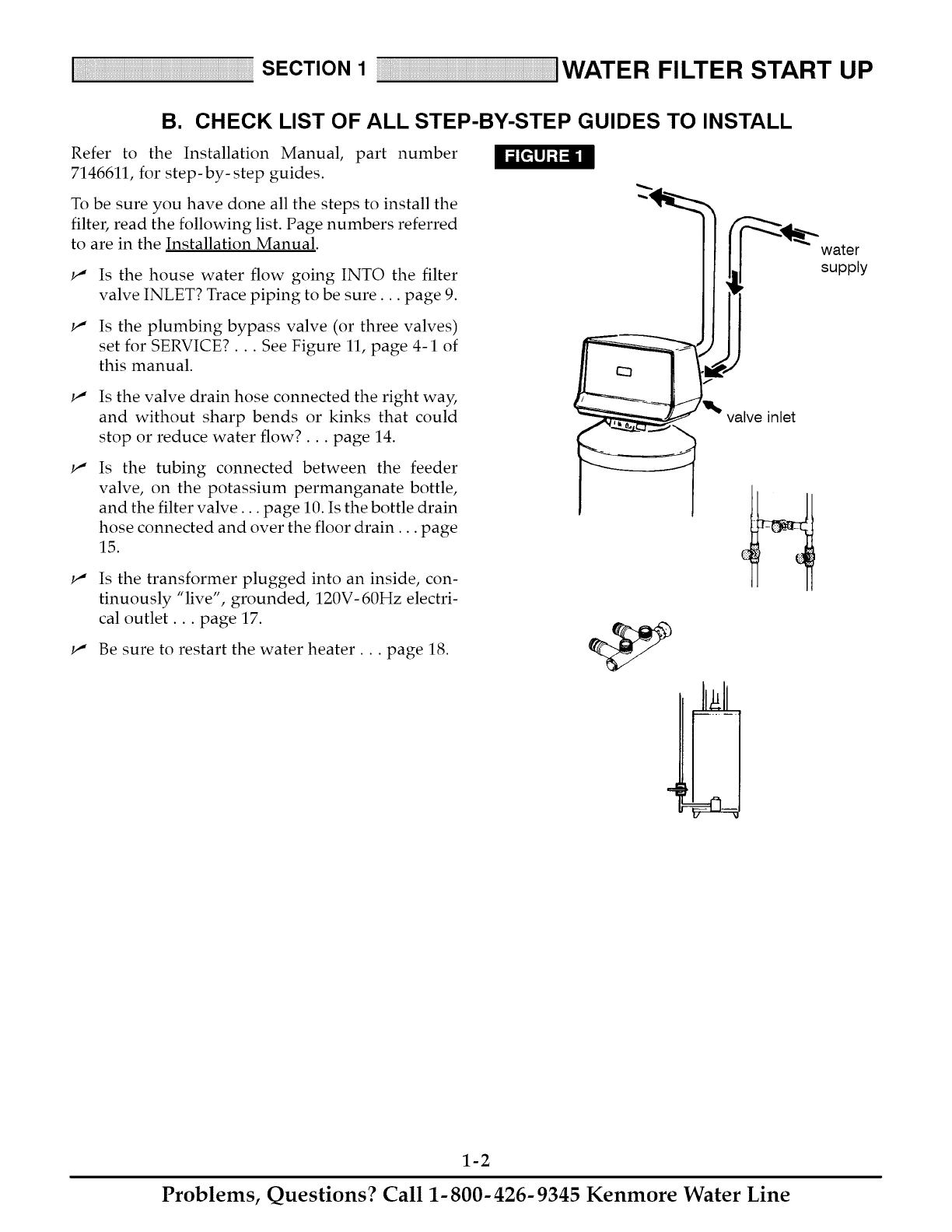
SECTION 1 IWATER FILTER START UP
B. CHECK LIST OF ALL STEP-BY-STEP GUIDES TO INSTALL
Refer to the Installation Manual, part number
7146611, for step-by-step guides.
To be sure you have done all the steps to install the
filter, read the following list. Page numbers referred
to are in the Installation Manual.
w"
w"
Is the house water flow going INTO the filter
valve INLET? Trace piping to be sure.., page 9.
Is the plumbing bypass valve (or three valves)
set for SERVICE?... See Figure 11, page 4-1 of
this manual.
w"
w"
w"
Is the valve drain hose connected the right way,
and without sharp bends or kinks that could
stop or reduce water flow?.., page 14.
Is the tubing connected between the feeder
valve, on the potassium permanganate bottle,
and the filter valve.., page 10. Is the bottle drain
hose connected and over the floor drain.., page
15.
Is the transformer plugged into an inside, con-
tinuously "live", grounded, 120V- 60Hz electri-
cal outlet.., page 17.
w" Be sure to restart the water heater.., page 18.
valve inlet
water
supply
1-2
Problems, Questions? Call 1-800-426-9345 Kenmore Water Line
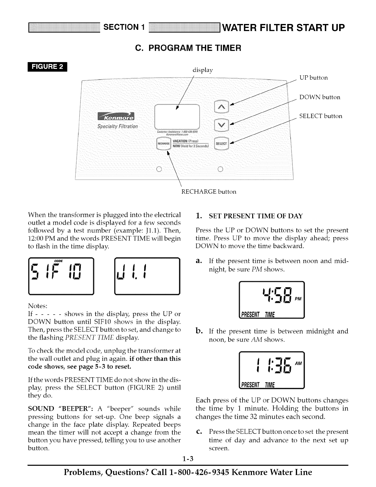
SECTION 1 IWATER FILTER START UP
C. PROGRAM THE TIMER
display
..................... 7- ......... UP button
/
/
/
,/ DOWN button
A
J
J
\
! \\
RECHARGE button
SELECT button
When the transformer is plugged into the electrical
outlet a model code is displayed for a few seconds
followed by a test number (example: J1.1). Then,
12:00 PM and the words PRESENT TIME will begin
to flash in the time display.
1. SET PRESENT TIME OF DAY
Press the UP or DOWN buttons to set the present
time. Press UP to move the display ahead; press
DOWN to move the time backward.
a. If the present time is between noon and mid-
night, be sure PM shows.
Notes:
If shows in the display, press the UP or
DOWN button until SIF10 shows in the display.
Then, press the SELECT button to set, and change to
the flashing PRESENT TIME display.
To check the model code, unplug the transformer at
the wall outlet and plug in again, if other than this
code shows, see page 5-3 to reset.
If the words PRESENT TIME do not show in the dis-
play, press the SELECT button (FIGURE 2) until
they do.
SOUND "BEEPER": A "beeper" sounds while
pressing buttons for set-up. One beep signals a
change in the face plate display. Repeated beeps
mean the timer will not accept a change from the
button you have pressed, telling you to use another
button.
b. If the present time is between midnight and
noon, be sure AM shows.
Each press of the UP or DOWN buttons changes
the time by 1 minute. Holding the buttons in
changes the time 32 minutes each second.
c. Press the SELECT button once to set the present
time of day and advance to the next set up
screen.
1-3
Problems, Questions? Call 1-800-426-9345 Kenmore Water Line
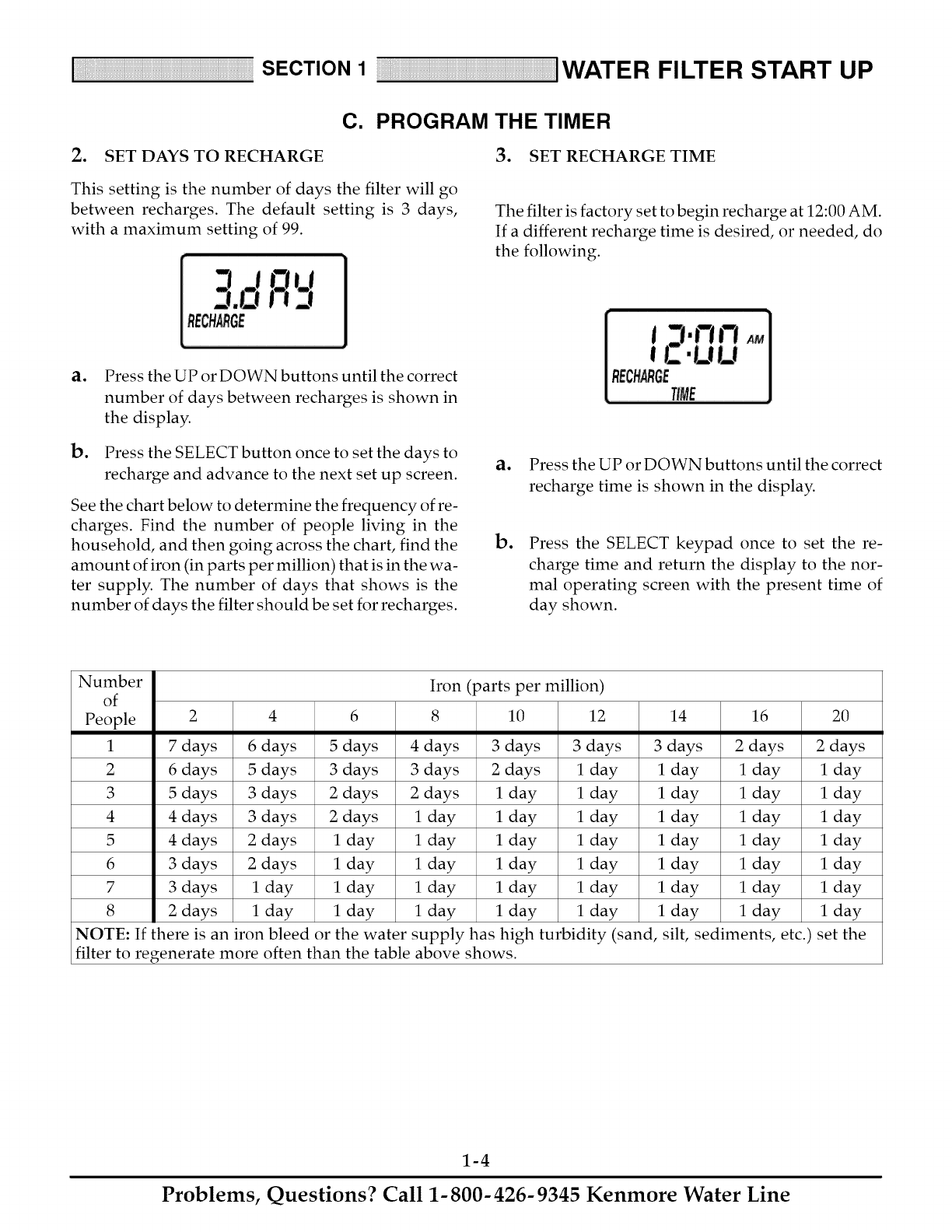
SECTION 1 IWATER FILTER START UP
C. PROGRAM THE TIMER
2. SET DAYS TO RECHARGE 3. SET RECHARGE TIME
This setting is the number of days the filter will go
between recharges. The default setting is 3 days,
with a maximum setting of 99.
-t
3.oR'_-,'
RECHarGE
The filter is factory set to begin recharge at 12:00 AM.
If a different recharge time is desired, or needed, do
the following.
ao Press the UP or DOWN buttons until the correct
number of days between recharges is shown in
the display.
b. Press the SELECT button once to set the days to
recharge and advance to the next set up screen.
See the chart below to determine the frequency of re-
charges. Find the number of people living in the
household, and then going across the chart, find the
amount of iron (in parts per million) that is in the wa-
ter supply. The number of days that shows is the
number of days the filter should be set for recharges.
ao
Do
Press the UP or DOWN buttons until the correct
recharge time is shown in the display.
Press the SELECT keypad once to set the re-
charge time and return the display to the nor-
mal operating screen with the present time of
day shown.
Number Iron (parts per million)
of
People 2 4 6 8 10 12 14 16 20
1 7 days 6 days 5 days 4 days 3 days 3 days 3 days 2 days 2 days
2 6 days 5 days 3 days 3 days 2 days 1 day 1 day 1 day 1 day
3 5 days 3 days 2 days 2 days 1 day 1 day 1 day 1 day 1 day
4 4 days 3 days 2 days 1 day 1 day 1 day 1 day 1 day 1 day
5 4 days 2 days 1 day 1 day 1 day 1 day 1 day 1 day 1 day
6 3 days 2 days 1 day 1 day 1 day 1 day 1 day 1 day 1 day
7 3 days 1 day 1 day 1 day 1 day 1 day 1 day 1 day 1 day
8 2 days 1 day 1 day 1 day 1 day 1 day 1 day 1 day 1 day
NOTE: If there is an iron bleed or the water supply has high turbidity (sand, silt, sediments, etc.) set the
filter to regenerate more often than the table above shows.
1-4
Problems, Questions? Call 1-800-426-9345 Kenmore Water Line
SECTION 1 IWATER FILTER START UP
D. SANITIZING THE WATER FILTER
Care is taken at the factory to keep your water filter
as clean and sanitary as possible. However, it is sug-
gested that the sanitizing procedure below is follo-
wed ,_1_
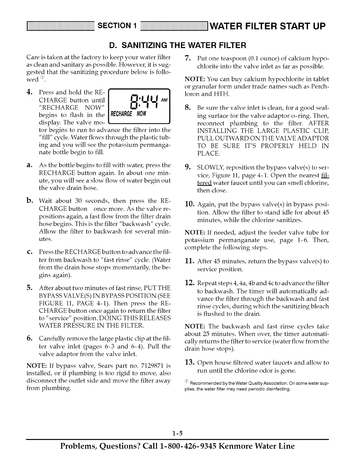
oPress and hold the RE-
CHARGE button until
"RECHARGE NOW"
begins to flash in the
display. The valve mo-
tor begins to run to advance the filter into the
"fill" cycle. Water flows through the plastic tub-
ing and you will see the potassium permanga-
nate bottle begin to fill.
7. Put one teaspoon (0.1 ounce) of calcium hypo-
chlorite into the valve inlet as far as possible.
NOTE: You can buy calcium hypochlorite in tablet
or granular form under trade names such as Perch-
loron and HTH.
go Be sure the valve inlet is clean, for a good seal-
ing surface for the valve adaptor o-ring. Then,
reconnect plumbing to the filter. AFTER
INSTALLING THE LARGE PLASTIC CLIP,
PULL OUTWARD ON THE VALVE ADAPTOR
TO BE SURE IT'S PROPERLY HELD IN
PLACE.
ao As the bottle begins to fill with water, press the
RECHARGE button again. In about one min-
ute, you will see a slow flow of water begin out
the valve drain hose.
Do Wait about 30 seconds, then press the RE-
CHARGE button once more. As the valve re-
positions again, a fast flow from the filter drain
hose begins. This is the filter "backwash" cycle.
Allow the filter to backwash for several min-
utes.
Co
o
Press the RECHARGE button to advance the fil-
ter from backwash to "fast rinse" cycle. (Water
from the drain hose stops momentarily, the be-
gins again).
After about two minutes of fast rinse, PUT THE
BYPASS VALVE(S) IN BYPASS POSITION (SEE
FIGURE 11, PAGE 4-1). Then press the RE-
CHARGE button once again to return the filter
to "service" position. DOING THIS RELEASES
WATER PRESSURE IN THE FILTER.
oCarefully remove the large plastic clip at the fil-
ter valve inlet (pages 6-3 and 6-4). Pull the
valve adaptor from the valve inlet.
NOTE: If bypass valve, Sears part no. 7129871 is
installed, or if plumbing is too rigid to move, also
disconnect the outlet side and move the filter away
from plumbing.
oSLOWLY, reposition the bypass valve(s) to ser-
vice, Figure 11, page 4-1. Open the nearest fil:
tered water faucet until you can smell chlorine,
then close.
10. Again, put the bypass valve(s) in bypass posi-
tion. Allow the filter to stand idle for about 45
minutes, while the chlorine sanitizes.
NOTE: If needed, adjust the feeder valve tube for
potassium permanganate use, page 1-6. Then,
complete the following steps.
11. After 45 minutes, return the bypass valve(s) to
service position.
12. Repeat steps 4, 4a, 4b and 4c to advance the filter
to backwash. The timer will automatically ad-
vance the filter through the backwash and fast
rinse cycles, during which the sanitizing bleach
is flushed to the drain.
NOTE: The backwash and fast rinse cycles take
about 25 minutes. When over, the timer automati-
cally returns the filter to service (water flow from the
drain hose stops).
13. Open house filtered water faucets and allow to
run until the chlorine odor is gone.
_ Recommended by the Water Quality Association. On some water sup-
plies, the water filter may need periodic disinfecting.
1-5
Problems, Questions? Call 1-800-426-9345 Kenmore Water Line
SECTION 1 IWATER FILTER START UP
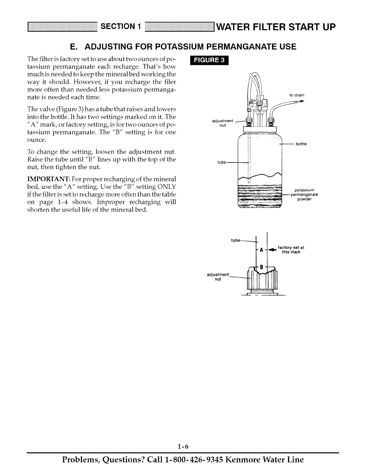
E. ADJUSTING FOR POTASSIUM PERMANGANATE USE
The filter is factory set to use about two ounces of po-
tassium permanganate each recharge. That's how
much is needed to keep the mineral bed working the
way it should. However, if you recharge the filer
more often than needed less potassium permanga-
nate is needed each time. to drain
The valve (Figure 3) has a tube that raises and lowers
into the bottle. It has two settings marked on it. The
"A" mark, or factory setting, is for two ounces of po-
tassium permanganate. The "B" setting is for one
ounce.
To change the setting, loosen the adjustment nut.
Raise the tube until "B" lines up with the top of the
nut, then tighten the nut.
IMPORTANT: For proper recharging of the mineral
bed, use the "A" setting. Use the "B" setting ONLY
if the filter is set to recharge more often than the table
on page 1-4 shows. Improper recharging will
shorten the useful life of the mineral bed.
adjustment
nut
tube --
-- bottle
potassium
-- permanganate
powder
factory set at
this mark
adjustment
nut
1-6
Problems, Questions? Call 1-800-426-9345 Kenmore Water Line
SECTION 2 HOW YOUR WATER FILTER WORKS
A. FACEPLATE TIMER FEATURES
S
E
C
T
N
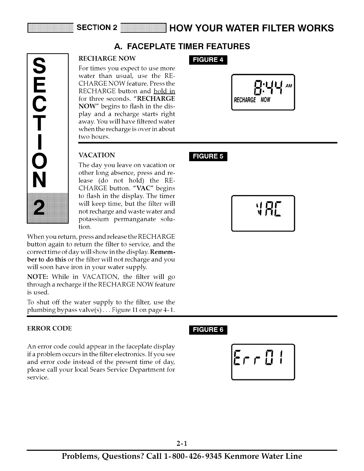
RECHARGE NOW
For times you expect to use more
water than usual, use the RE-
CHARGE NOW feature. Press the
RECHARGE button and hold in
for three seconds. "RECHARGE
NOW" begins to flash in the dis-
play and a recharge starts right
away. You will have filtered water
when the recharge is over in about
two hours.
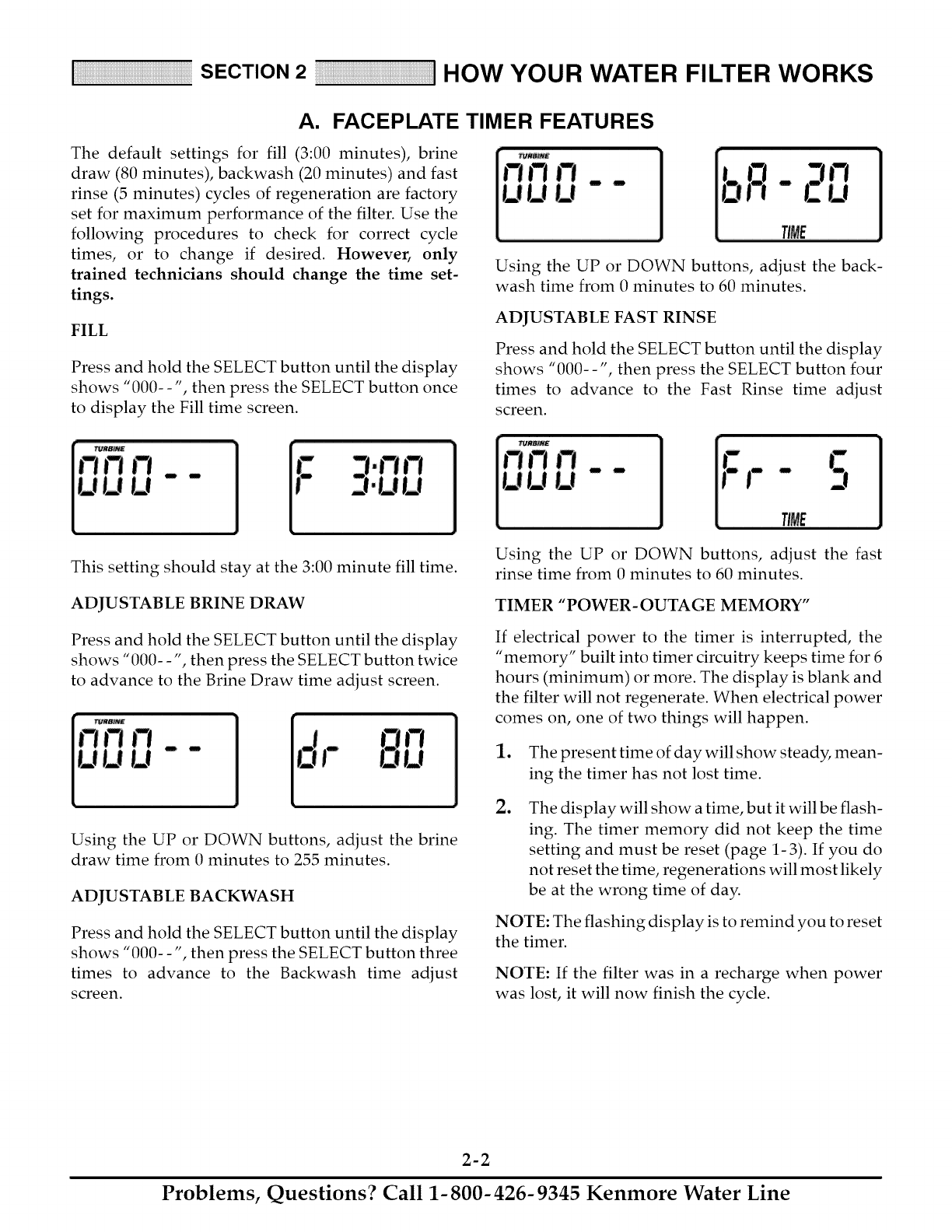
VACATION
The day you leave on vacation or
other long absence, press and re-
lease (do not hold) the RE-
CHARGE button. "VAC" begins
to flash in the display. The timer
will keep time, but the filter will
not recharge and waste water and
potassium permanganate solu-
tion.
When you return, press and release the RECHARGE
button again to return the filter to service, and the
correct time of day will show in the display. Remem-
ber to do this or the filter will not recharge and you
will soon have iron in your water supply.
NOTE: While in VACATION, the filter will go
through a recharge if the RECHARGE NOW feature
is used.
To shut off the water supply to the filter, use the
plumbing bypass valve(s)... Figure 11 on page 4-1.
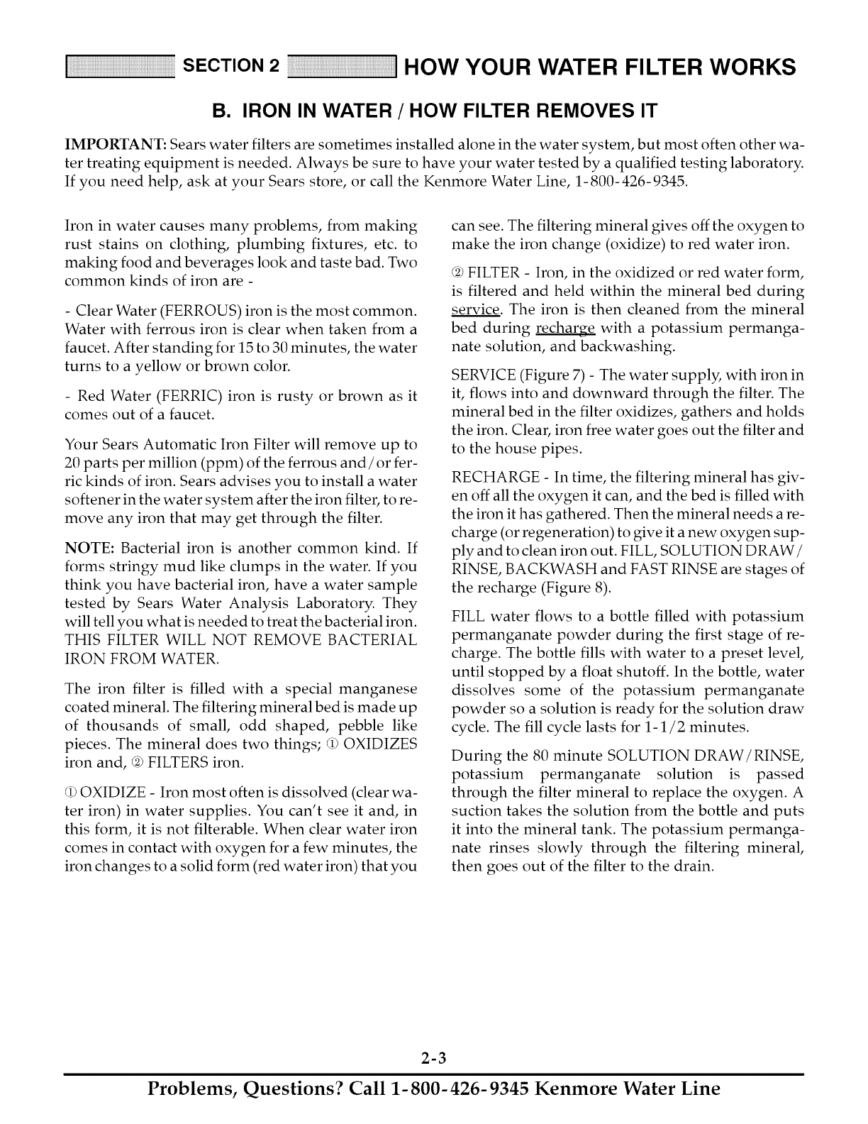
ERROR CODE
An error code could appear in the faceplate display
if a problem occurs in the filter electronics. If you see
and error code instead of the present time of day,
please call your local Sears Service Department for
service.
2-1
Problems, Questions? Call 1-800-426-9345 Kenmore Water Line
SECTION 2 HOW YOUR WATER FILTER WORKS
A. FACEPLATE TIMER FEATURES
The default settings for fill (3:00 minutes), brine
draw (80 minutes), backwash (20 minutes) and fast
rinse (5 minutes) cycles of regeneration are factory
set for maximum performance of the filter. Use the
following procedures to check for correct cycle
times, or to change if desired. However, only
trained technicians should change the time set-
tings.
FILL
Press and hold the SELECT button until the display
shows "000--', then press the SELECT button once
to display the Fill time screen.
Using the UP or DOWN buttons, adjust the back-
wash time from 0 minutes to 60 minutes.
ADJUSTABLE FAST RINSE
Press and hold the SELECT button until the display
shows "000--', then press the SELECT button four
times to advance to the Fast Rinse time adjust
screen.
This setting should stay at the 3:00 minute fill time.
ADJUSTABLE BRINE DRAW
Press and hold the SELECT button until the display
shows "000- -", then press the SELECT button twice
to advance to the Brine Draw time adjust screen.
U
Using the UP or DOWN buttons, adjust the brine
draw time from 0 minutes to 255 minutes.
ADJUSTABLE BACKWASH
Press and hold the SELECT button until the display
shows "000--', then press the SELECT button three
times to advance to the Backwash time adjust
screen.
Using the UP or DOWN buttons, adjust the fast
rinse time from 0 minutes to 60 minutes.
TIMER "POWER-OUTAGE MEMORY"
If electrical power to the timer is interrupted, the
"memory" built into timer circuitry keeps time for 6
hours (minimum) or more. The display is blank and
the filter will not regenerate. When electrical power
comes on, one of two things will happen.
1. The present time of day will show steady, mean-
ing the timer has not lost time.
oThe display will show a time, but it will be flash-
ing. The timer memory did not keep the time
setting and must be reset (page 1-3). If you do
not reset the time, regenerations will most likely
be at the wrong time of day.
NOTE: The flashing display is to remind you to reset
the timer.
NOTE: If the filter was in a recharge when power
was lost, it will now finish the cycle.
2-2
Problems, Questions? Call 1-800-426-9345 Kenmore Water Line
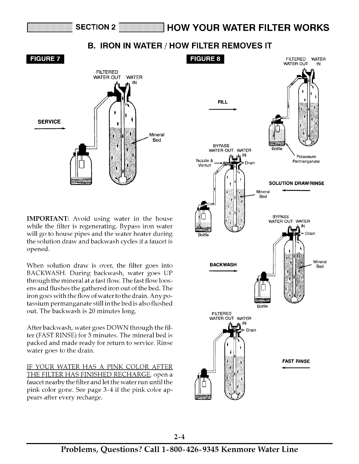
SECTION 2 HOW YOUR WATER FilTER WORKS
B. IRON IN WATER /HOW FILTER REMOVES IT
IMPORTANT: Sears water filters are sometimes installed alone in the water system, but most often other wa-
ter treating equipment is needed. Always be sure to have your water tested by a qualified testing laboratory.
If you need help, ask at your Sears store, or call the Kenmore Water Line, 1- 800- 426- 9345.
Iron in water causes many problems, from making
rust stains on clothing, plumbing fixtures, etc. to
making food and beverages look and taste bad. Two
common kinds of iron are -
- Clear Water (FERROUS) iron is the most common.
Water with ferrous iron is clear when taken from a
faucet. After standing for 15 to 30 minutes, the water
turns to a yellow or brown color.
- Red Water (FERRIC) iron is rusty or brown as it
comes out of a faucet.
Your Sears Automatic Iron Filter will remove up to
20 parts per million (ppm) of the ferrous and/or fer-
ric kinds of iron. Sears advises you to install a water
softener in the water system after the iron filter, to re-
move any iron that may get through the filter.
NOTE: Bacterial iron is another common kind. If
forms stringy mud like clumps in the water. If you
think you have bacterial iron, have a water sample
tested by Sears Water Analysis Laboratory. They
will tell you what is needed to treat the bacterial iron.
THIS FILTER WILL NOT REMOVE BACTERIAL
IRON FROM WATER.
The iron filter is filled with a special manganese
coated mineral. The filtering mineral bed is made up
of thousands of small, odd shaped, pebble like
pieces. The mineral does two things; (1) OXIDIZES
iron and, (2) FILTERS iron.
(1)OXIDIZE - Iron most often is dissolved (clear wa-
ter iron) in water supplies. You can't see it and, in
this form, it is not filterable. When clear water iron
comes in contact with oxygen for a few minutes, the
iron changes to a solid form (red water iron) that you
can see. The filtering mineral gives off the oxygen to
make the iron change (oxidize) to red water iron.
@ FILTER - Iron, in the oxidized or red water form,
is filtered and held within the mineral bed during
service. The iron is then cleaned from the mineral
bed during recharge with a potassium permanga-
nate solution, and backwashing.
SERVICE (Figure 7) - The water supply, with iron in
it, flows into and downward through the filter. The
mineral bed in the filter oxidizes, gathers and holds
the iron. Clear, iron free water goes out the filter and
to the house pipes.
RECHARGE - In time, the filtering mineral has giv-
en off all the oxygen it can, and the bed is filled with
the iron it has gathered. Then the mineral needs a re-
charge (or regeneration) to give it a new oxygen sup-
ply and to clean iron out. FILL, SOLUTION DRAW/
RINSE, BACKWASH and FAST RINSE are stages of
the recharge (Figure 8).
FILL water flows to a bottle filled with potassium
permanganate powder during the first stage of re-
charge. The bottle fills with water to a preset level,
until stopped by a float shutoff. In the bottle, water
dissolves some of the potassium permanganate
powder so a solution is ready for the solution draw
cycle. The fill cycle lasts for 1-1/2 minutes.
During the 80 minute SOLUTION DRAW/RINSE,
potassium permanganate solution is passed
through the filter mineral to replace the oxygen. A
suction takes the solution from the bottle and puts
it into the mineral tank. The potassium permanga-
nate rinses slowly through the filtering mineral,
then goes out of the filter to the drain.
2-3
Problems, Questions? Call 1-800-426-9345 Kenmore Water Line
SECTION 2 HOW YOUR WATER FilTER WORKS
B. IRON IN WATER /HOW FILTER REMOVES IT
SERVICE
FILTERED
WATER OUT WATER
IN
Mineral
Bed
IMPORTANT: Avoid using water in the house
while the filter is regenerating. Bypass iron water
will go to house pipes and the water heater during
the solution draw and backwash cycles if a faucet is
opened.
When solution draw is over, the filter goes into
BACKWASH. During backwash, water goes UP
through the mineral at a fast flow. The fast flow loos-
ens and flushes the gathered iron out of the bed. The
iron goes with the flow of water to the drain. Any po-
tassium permanganate still in the bed is also flushed
out. The backwash is 20 minutes long.
After backwash, water goes DOWN through the fil-
ter (FAST RINSE) for 5 minutes. The mineral bed is
packed and made ready for return to service. Rinse
water goes to the drain.
IF YOUR WATER HAS A PINK COLOR AFTER
THE FILTER HAS FINISHED RECHARGE, open a
faucet nearby the filter and let the water run until the
pink color gone. See page 3-4 if the pink color ap-
pears after every recharge.
FILL
)
BYPASS
WATER OUT WATER
IN
Nozzle &
Venturi
Bottle
BACKWASH
Bottle
FILTERED WATER
WATER OUT IN
i
\Potassium
Permanganate
SOLUTION DRAW/RINSE
Mineral
Bed
Bottle
FILTERED
WATER OUT WATER
_- Drain
BYPASS
WATER OUT WATER
IN
Drain
Mineral
Bed
FAST RINSE
q
2-4
Problems, Questions? Call 1-800-426-9345 Kenmore Water Line
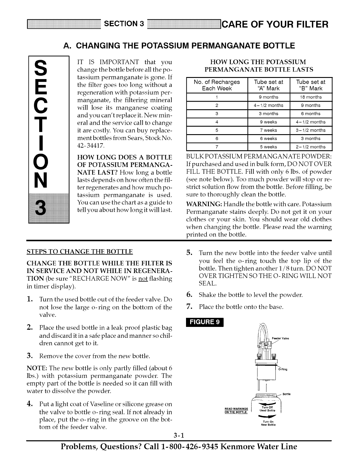
A. CHANGING THE POTASSIUM PERMANGANATE BOTTLE
S
C
T
N
IT IS IMPORTANT that you
change the bottle before all the po-
tassium permanganate is gone. If
the filter goes too long without a
regeneration with potassium per-
manganate, the filtering mineral
will lose its manganese coating
and you can't replace it. New min-
eral and the service call to change
it are costly. You can buy replace-
ment bottles from Sears, Stock No.
42- 34417.
HOW LONG DOES A BOTTLE
OF POTASSIUM PERMANGA-
NATE LAST? How long a bottle
lasts depends on how often the fil-
ter regenerates and how much po-
tassium permanganate is used.
You can use the chart as a guide to
tell you about how long it will last.
HOW LONG THE POTASSIUM
PERMANGANATE BOTTLE LASTS
No. of Recharges Tube set at Tube set at
Each Week "A" Mark "B" Mark
1 9 months 18 months
2 4-1/2 months 9 months
3 3 months 6 months
4 9 weeks 4-1/2 months
5 7 weeks 3-1/2 months
6 6 weeks 3 months
7 5 weeks 2-1/2 months
BULK POTASSIUM PERMANGANATE POWDER:
If purchased and used in bulk form, DO NOT OVER
FILL THE BOTTLE. Fill with only 6 lbs. of powder
(see note below). Too much powder will stop or re-
strict solution flow from the bottle. Before filling, be
sure to thoroughly clean the bottle.
WARNING: Handle the bottle with care. Potassium
Permanganate stains deeply. Do not get it on your
clothes or your skin. You should wear old clothes
when changing the bottle. Please read the warning
printed on the bottle.
STEPS TO CHANGE THE BOTTLE
CHANGE THE BOTTLE WHILE THE FILTER IS
IN SERVICE AND NOT WHILE IN REGENERA-
TION (be sure "RECHARGE NOW" is not flashing
in timer display).
1. Turn the used bottle out of the feeder valve. Do
not lose the large o-ring on the bottom of the
valve.
oTurn the new bottle into the feeder valve until
you feel the o-ring touch the top lip of the
bottle. Then tighten another 1/8 turn. DO NOT
OVER TIGHTEN SO THE O- RING WILL NOT
SEAL.
6. Shake the bottle to level the powder.
7. Place the bottle onto the base.
oPlace the used bottle in a leak proof plastic bag
and discard it in a safe place and manner so chil-
dren cannot get to it.
3. Remove the cover from the new bottle.
NOTE: The new bottle is only partly filled (about 6
lbs.) with potassium permanganate powder. The
empty part of the bottle is needed so it can fill with
water to dissolve the powder.
oPut a light coat of Vaseline or silicone grease on
the valve to bottle o- ring seal. If not already in
place, put the o-ring in the groove on the bot-
tom of the feeder valve.
3-1
Feeder Valve
I
__ Bottle
Turn Off
READ WARNINGS {Used Bottle
ON THE BOTTLE.
Turn On
New Bottle
Problems, Questions? Call 1-800-426-9345 Kenmore Water Line
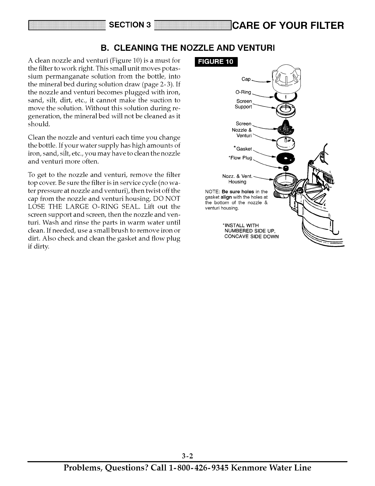
B. CLEANING THE NOZZLE AND VENTURI
A clean nozzle and venturi (Figure 10) is a must for
the filter to work right. This small unit moves potas-
sium permanganate solution from the bottle, into
the mineral bed during solution draw (page 2- 3). If
the nozzle and venturi becomes plugged with iron,
sand, silt, dirt, etc., it cannot make the suction to
move the solution. Without this solution during re-
generation, the mineral bed will not be cleaned as it
should.
Clean the nozzle and venturi each time you change
the bottle. If your water supply has high amounts of
iron, sand, silt, etc., you may have to clean the nozzle
and venturi more often.
To get to the nozzle and venturi, remove the filter
top cover. Be sure the filter is in service cycle (no wa-
ter pressure at nozzle and venturi), then twist off the
cap from the nozzle and venturi housing. DO NOT
LOSE THE LARGE O-RING SEAL. Lift out the
screen support and screen, then the nozzle and ven-
turi. Wash and rinse the parts in warm water until
clean. If needed, use a small brush to remove iron or
dirt. Also check and clean the gasket and flow plug
if dirty.
Cap _ ___
O-Ring ......_......__ ___
Screen V
Sup po rt _"'--_--.-_._
Screen _Nozzle &
Venturi _ 0
\
*Flow Plug
I,
Nozz. & Vent.
Housing
NOTE: Be sure holes in the
gasket align with the holes at
the bottom of the nozzle &
venturi housing.
* INSTALL _
WITH
NUMBERED SIDE UP,
CONCAVE SIDE DOWN
3-2
Problems, Questions? Call 1-800-426-9345 Kenmore Water Line
C. KEEP THE FILTER FROM FREEZING
If the filter is installed where it could freeze (summer
cabin, lake home, etc.) you must drain all water from
it to stop possible damage caused by freezing. To
drain the filter-
1. Close the shutoff valve on the house main water
pipe, near the water meter or pressure tank.
2. Open a faucet in the filtered water pipes to vent
pressure in the filter.
3. Looking at Figure 11 on page 4-1, move the
stem in a single bypass valve to bypass. Close
the inlet and outlet valves in a three valve by-
pass system, and open the bypass valve.
Unplug the transformer at the wall outlet.
o
5.
o
Pull the holding clip to remove the drain fitting,
with drain hose attached, from the valve. DO
NOT LOSE THE BLACK RUBBER FLOW
PLUG AND RETAINER.
Looking at page 11 in the installation manual,
remove the plastic clips and pull the adaptors or
bypass valve from the inlet and outlet.
oRemove the bottle and feeder valve from the
base. Store the bottle in a warm, safe place
where it will not spill, and AWAY FROM CHIL-
DREN.
If you do not have a place to SAFELY store the bottle,
turn the feeder valve off and flush with fresh water.
Dump the liquid contents of the bottle down the
drain. Place the bottle in a plastic bag and discard in
a safe place and manner so children cannot get to it.
go
o
Move the filter close to the floor drain. SLOWLY
and CAREFULLY (the filter is heavy) tip the fil-
ter over so the valve inlet and outlet are over the
drain. DO NOT REST THE FILTER ON THE IN-
LET AND OUTLET FITTINGS OR THEY WILL
BREAK.
Tip the bottom of the filter up a few inches and
hold until all water has drained. Leave the filter
laying like this until you are ready to use it. Plug
the inlet and outlet with rags to keep dirt, bugs,
etc. out.
3-3
Problems, Questions? Call 1-800-426-9345 Kenmore Water Line
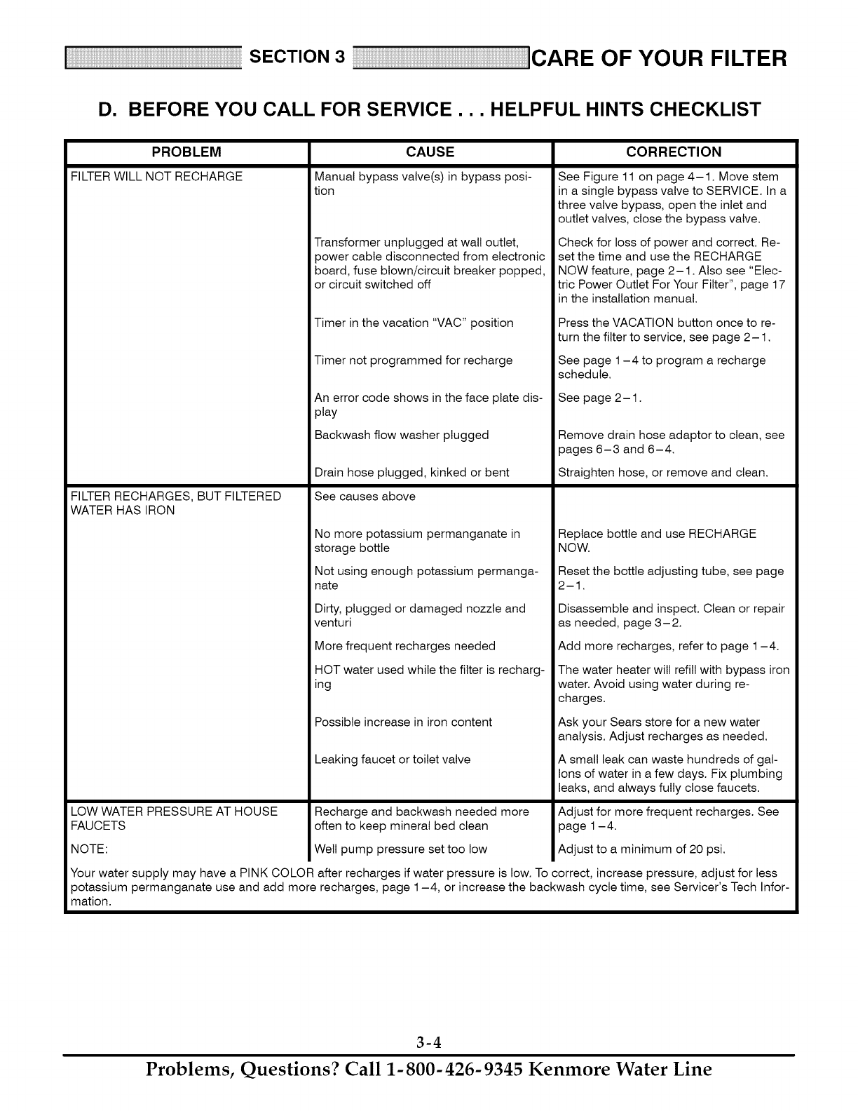
D. BEFORE YOU CALL FOR SERVICE... HELPFUL HINTS CHECKLIST
PROBLEM
FILTERWILL NOT RECHARGE
FILTER RECHARGES, BUT FILTERED
WATER HAS IRON
LOW WATER PRESSURE AT HOUSE
FAUCETS
NOTE:
CAUSE
Manual bypass valve(s) in bypass posi-
tion
Transformer unplugged at wall outlet,
power cable disconnected from electronic
board, fuse blown/circuit breaker popped,
or circuit switched off
Timer in the vacation "VAC" position
Timer not programmed for recharge
An error code shows in the face plate dis-
play
Backwash flow washer plugged
Drain hose plugged, kinked or bent
See causes above
No more potassium permanganate in
storage bottle
Not using enough potassium permanga-
nate
Dirty, plugged or damaged nozzle and
venturi
More frequent recharges needed
HOT water used while the filter is recharg-
ing
Possible increase in iron content
Leaking faucet or toilet valve
Recharge and backwash needed more
often to keep mineral bed clean
Well pump pressure set too low
CORRECTION
See Figure 11 on page 4-1. Move stem
in a single bypass valve to SERVICE. In a
three valve bypass, open the inlet and
outlet valves, close the bypass valve.
Check for loss of power and correct. Re-
set the time and use the RECHARGE
NOW feature, page 2-1. Also see "Elec-
tric Power Outlet For Your Filter", page 17
in the installation manual.
Press the VACATION button once to re-
turn the filter to service, see page 2-1.
See page 1-4 to program a recharge
schedule.
See page 2-1.
Remove drain hose adaptor to clean, see
pages 6-3 and 6-4.
Straighten hose, or remove and clean.
Replace bottle and use RECHARGE
NOW.
Reset the bottle adjusting tube, see page
2-1.
Disassemble and inspect. Clean or repair
as needed, page 3-2.
Add more recharges, refer to page 1-4.
The water heater will refill with bypass iron
water. Avoid using water during re-
charges.
Ask your Sears store for a new water
analysis. Adjust recharges as needed.
A small leak can waste hundreds of gal-
lons of water in a few days. Fix plumbing
leaks, and always fully close faucets.
Adjust for more frequent recharges. See
page 1-4.
Adjust to a minimum of 20 psi.
Your water supply may have a PINK COLOR after recharges if water pressure is low. To correct, increase pressure, adjust for less
potassium permanganate use and add more recharges, page 1-4, or increase the backwash cycle time, see Servicer's Tech Infor-
mation.
3-4
Problems, Questions? Call 1-800-426-9345 Kenmore Water Line
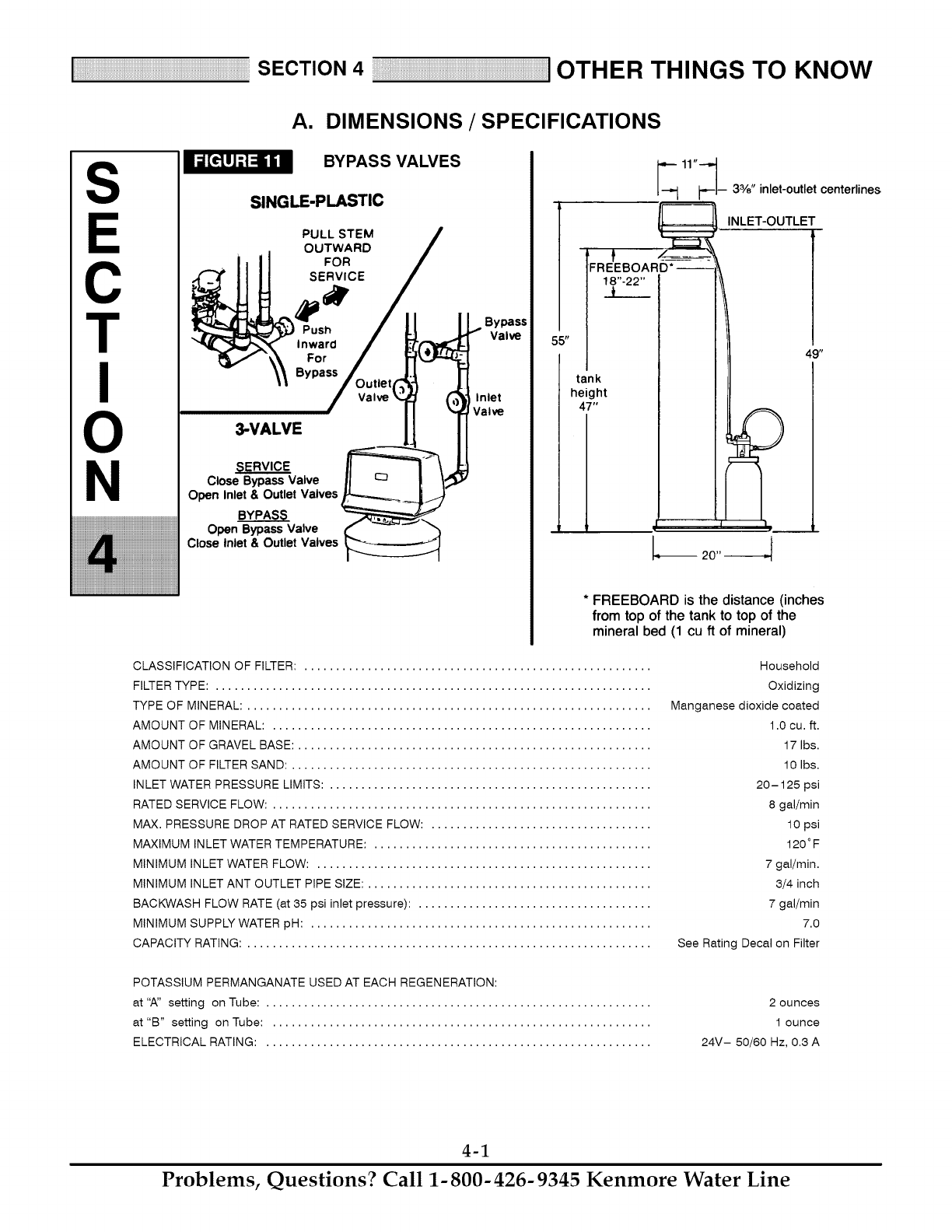
SECTION 4 I OTHER THINGS TO KNOW
A. DIMENSIONS /SPECIFICATIONS
I_[_ilil BYPASS VALVES
Ss SINGLE-PLASTIC
PULL STEM J
OUTWARD /
Tc
3-VALVE 11 II
CloseBypassValve II _ P I¢°"
Open Valves
Inlet & Outlet _ q
...........................................................................................................................................CloseOpenlnletBYPASS_Bypass& OutletValveValves
_11"--__ 3%" inlet-outlet centerlines
/FREEBOARI_------_- ',_ -_
* FREEBOARD is the distance (inches
from top of the tank to top of the
mineral bed (1 cu ft of mineral)
CLASSIFICATION OF FILTER: ....................................................... Household
FILTER TYPE: ..................................................................... Oxidizing
TYPE OF MINERAL: ................................................................ Manganese dioxide coated
AMOUNT OF MINERAL: ............................................................
AMOUNT OF GRAVEL BASE: ........................................................
AMOUNT OF FILTER SAND: .........................................................
INLET WATER PRESSURE LIMITS: ...................................................
RATED SERVICE FLOW: ............................................................
MAX. PRESSURE DROP AT RATED SERVICE FLOW: ...................................
MAXIMUM INLET WATER TEMPERATURE: ............................................
MINIMUM INLET WATER FLOW: .....................................................
MINIMUM INLET ANT OUTLET PIPE SIZE: .............................................
BACKWASH FLOW RATE (at 65 psi inlet pressure): .....................................
MINIMUM SUPPLY WATER pH: ......................................................
CAPACITY RATING: ................................................................
1.0 cu. ft.
17 Ibs.
10 Ibs.
20-125 psi
8 gal/min
10 psi
120°F
7 gal/min.
3/4 inch
7 gal/min
7.0
See Rating Decal on Filter
POTASSIUM PERMANGANATE USED AT EACH REGENERATION:
at "A" setting on Tube: .............................................................
at "B" setting on Tube: ............................................................
ELECTRICAL RATING: .............................................................
2 ounces
1 ounce
24V- 50/60 Hz, 0.3 A
4-1
Problems, Questions? Call 1-800-426-9345 Kenmore Water Line
SECTION 4 ] OTHER THINGS TO KNOW
B. NOTES
4-2
Problems, Questions? Call 1-800-426-9345 Kenmore Water Line
S
C
T
N
SECTION5 SERVICE TECH. INFORMATION
A. TROUBLESHOOTING
WIRING SCHEMATIC
24VAC
. 11f
TRANSFORMER
]] E--
NC
NO
POSITION
SWITCH
FACE PLATE TIMER
_v
A
IMPORTANT: KEEP THIS MANUAL WITH YOUR WATER FILTER. IF REPAIRS ARE NEEDED, THE SER-
VICE TECHNICIAN MUST HAVE THE INFORMATION ON THE FOLLOWING PAGES.
5-1
Problems, Questions? Call 1-800-426-9345 Kenmore Water Line
SECTION 5SERVICE TECH. INFORMATION
A. TROUBLESHOOTING
ALWAYS MAKE THESE INITIAL CHECKS FIRST
1. Does the time display show the correct time of
day?
...If display is blank, check power source to the filter.
...If time is flashing, power was off for over two
days. The filter resumes normal operation but re-
charges occur at the wrong time.
2. Plumbing bypass valve(s) must be in SERVICE
position (see Figure 11, page 4-1).
3. The inlet and outlet pipes must connect to the fil-
ter inlet and outlet respectively.
4. Is the transformer plugged into a "live" grounded
wall outlet, and the power cable fastened securely?
5. The valve drain hose must be free of kinks and
sharp bends.
If you do not find the problem after making the ini-
tial checks, do the MANUAL ADVANCE DIAG-
NOSTICS.
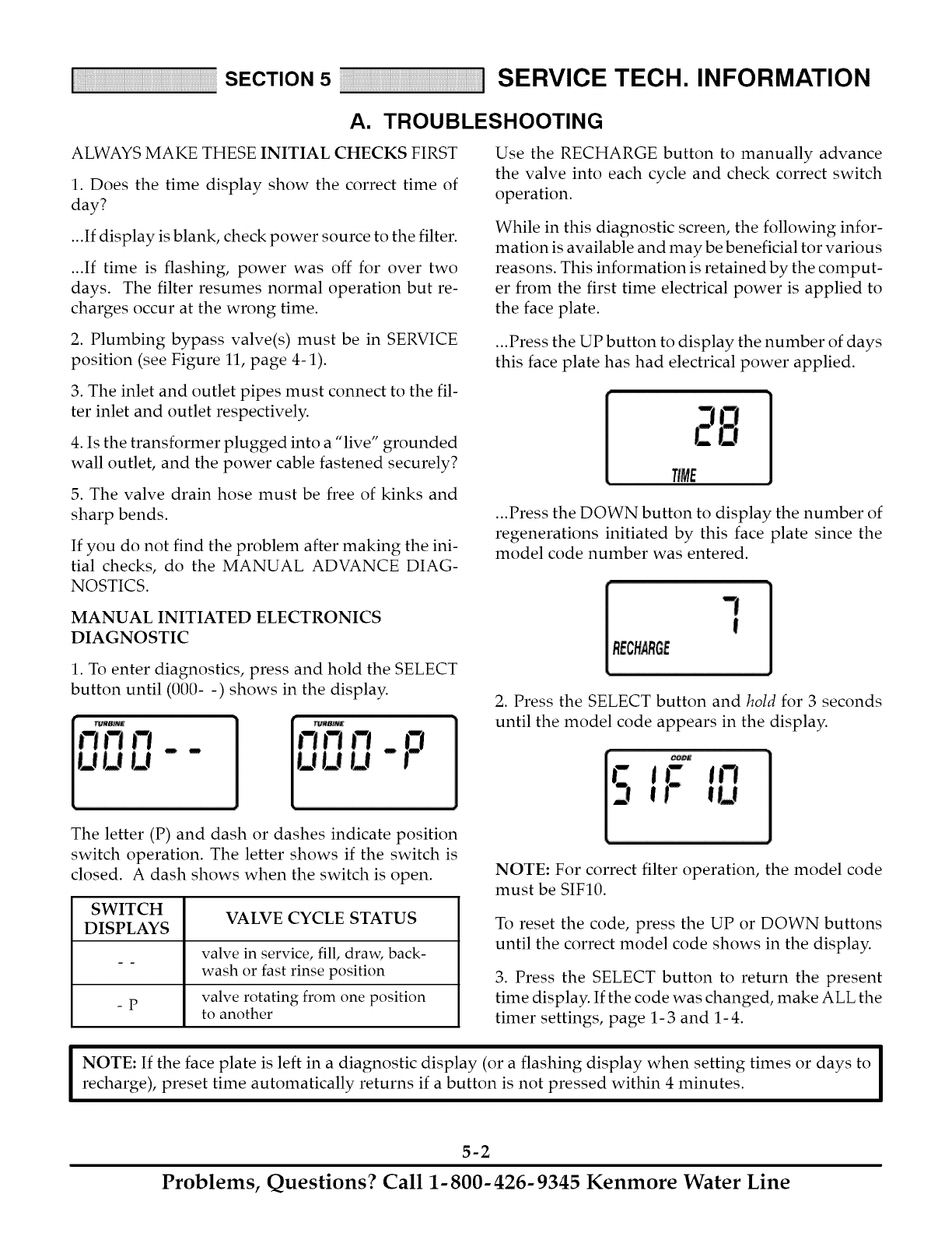
MANUAL INITIATED ELECTRONICS
DIAGNOSTIC
1. To enter diagnostics, press and hold the SELECT
button until (000- -) shows in the display.
Use the RECHARGE button to manually advance
the valve into each cycle and check correct switch
operation.
While in this diagnostic screen, the following infor-
mation is available and may be beneficial tor various
reasons. This information is retained by the comput-
er from the first time electrical power is applied to
the face plate.
...Press the UP button to display the number of days
this face plate has had electrical power applied.
TIME
...Press the DOWN button to display the number of
regenerations initiated by this face plate since the
model code number was entered.
RECHARGE
2. Press the SELECT button and hold for 3 seconds
until the model code appears in the display.
The letter (P) and dash or dashes indicate position
switch operation. The letter shows if the switch is
closed. A dash shows when the switch is open.
SWITCH VALVE CYCLE STATUS
DISPLAYS
valve in service, fill, draw, back-
wash or fast rinse position
valve rotating from one position
-p to another
NOTE: For correct filter operation, the model code
must be SIF10.
To reset the code, press the UP or DOWN buttons
until the correct model code shows in the display.
3. Press the SELECT button to return the present
time display. If the code was changed, make ALL the
timer settings, page 1-3 and 1-4.
IOTE: If the face plate is left in a diagnostic display (or a flashing display when setting times or days to I
recharge), preset time automatically returns if a button is not pressed within 4 minutes. I
5-2
Problems, Questions? Call 1-800-426-9345 Kenmore Water Line
SECTION 5SERVICE TECH. INFORMATION
A. TROUBLESHOOTING
MANUAL ADVANCE DIAGNOSTICS
Use the following procedures to advance the filter
valve through the regeneration cycles to check op-
eration.
Remove the top cover to observe cam and switch op-
eration during valve rotation.
DISPLAY MUST SHOW TIME AND DAY
...restriction in valve drain, causing a back- pressure
(bends, kinks, elevated too high, etc.),
...obstruction in brine valve or brine tubing
...inner valve failure (obstructed rotor disc, wave
washer defective, etc.)
3. Again press the RECHARGE button to move the
valve into backwash. Look for a fast flow of water
from the drain hose (see specifications, page 4-1).
1. Press and hold the RECHARGE button for 3 sec-
onds until RECHARGE NOW flashes in the display
and the filter moves into the fill cycle.
...An obstructed flow indicates a plugged top dis-
tributor, backwash flow plug, or drain hose.
Be sure household water pressure (well system) is
maintained at a minimum of 20 psi. Adjust the
pump switch upward, if needed.
...If the motor does not run, check the motor and all
wiring connections.
Check for fill water flow to the brine tank. If water
does not enter the tank, look for an obstructed
nozzle and venturi, fill flow plug or brine tubing.
2. After verifying fill, press the RECHARGE button
to move the valve into solution draw. A slow flow of
water to the drain will begin. Verify solution draw
from the brine tank by shining the flashlight into the
brinewell and observing a noticeable drop in the liq-
uid level.
If the unit does not draw brine, check for...
...dirty or defective nozzle and venturi
...nozzle and venturi not seated on the gasket, or
gasket defective
4. Press the RECHARGE button to move the filter
into fast rinse. Again, look for a drain flow rate about
the same as backwash.
5. To return the filter to service, press the RE-
CHARGE button once.
OTHER SERVICE
UNFILTERED WATER BYPASS (unfiltered water
"bleeds" into filtered water supply.
1. Missing or defective o-ring(s) at resin tank to
valve connection.
2. Defective rotor disc, seal or wave washer.
WATER LEAKS FROM DRAIN HOSE (during ser-
vice)
1. Defective rotor disc, seal, or wave washer.
2. Defective o-ring on disc shaft.
AUTOMATIC ELECTRONIC DIAGNOSTICS
The face plate has a self diagnostic function for the
electrical systems (except input power). The face
plate monitors the electronic components and cir-
cuits for correct operation. If a malfunction occurs,
an error code appears in the face plate display.
POSSIBLE DEFECT
CODE
Err 01, Err 03
& Err 04
Err 05
MOST LIKELY _ .... _ LEAST LIKELY
wiring harness or connection to position switch /switch /valve defect causing high torque /
motor inoperative
faceplate
PROCEDURE FOR REMOVING ERROR CODE FROM FACEPLATE: 1. Unplug transformer .... 2. Correct de-
fect .... 3. Plug in transformer .... 4. Wait for 12 minutes. The error code will return if the defect was not corrected. Press and hold the
RECHARGE button for 3 seconds as an alternate way to clear an error code.
5-3
Problems, Questions? Call 1-800-426-9345 Kenmore Water Line
SECTION 5SERVICE TECH. INFORMATION
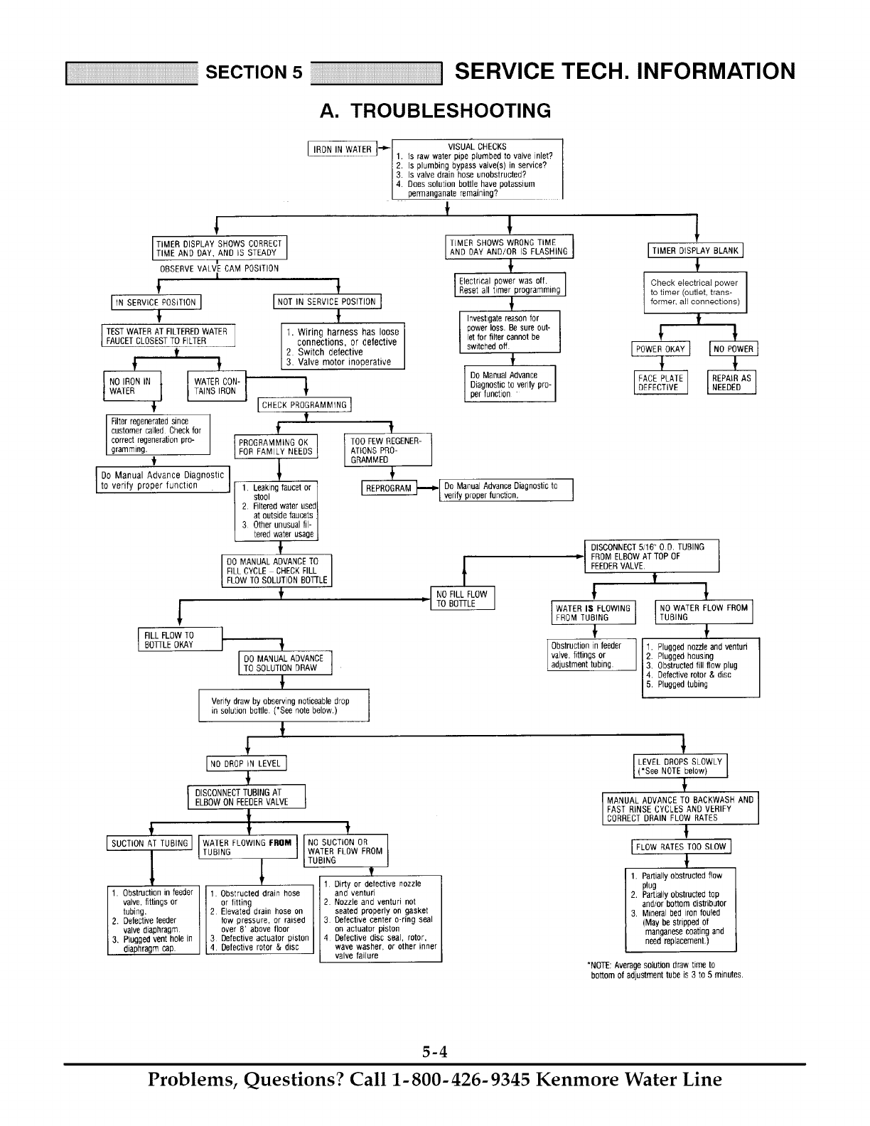
A. TROUBLESHOOTING
TIMER DISPLAY SHOWS CORRECT
TIME AND DAY, AND iS STEADY
OBSERVE VALVlE CAM POSITION
|
I
I,NSERV,CEPOSIT,ONI
TEST WATER AT FILTERED WATER
FAUCETCLOSESTTO FILTER
f
f f
I NO IRON IN I WATER CON-
WATER t ITAINSIRON 1
I
Filter regenerated since
customer called. Check for _'
correct regeneration pro- PROGRAMMING OK
gramming. FOR FAM LY NEEDS
Do ManualAdvance Diagnostic
to verify proper function 1. Leaking faucet or
stool J
2Filteredwater usedI
at outside faucets ]
3 Other unusual fil-
tered water usage
f
DO MANUAL ADVANCE TO I
FILL CYCLE CHECKFILL
FLOW TO SOLUTION BOTTLE
f
!
I ILL FLOW TO
BOTrLE OKAY
!
I NOT IN SERVICE POSITION I
!
1. Wiring harness has loose
connections, or defective
Switch defective
i Valve motor inoperative
I IRON IN WATER ]-_'I VISUAl_ CHECKS
1. Is raw water pipe plumbed to valve inlet?
2. Is plumbing bypass valve(s) in service?
3. Is valve drain hose unobstructed?
4. Does solution bottle have potassium
permanganate remaining?
f!
IIMER SHOWS WRONG TIME I
AND DAY AND/OR IS FLASHING ]
g
÷
I Electrical power was off.
Reset all timer programming
Investigate reason for I
power loss. Be sure out- I
let for filter cannot be
switched off fI
Do Manual Advance I
,_ Diagnostic to verify pro- Iper function "
[CHECK PROGRAMMING l
ff
TOO FEW REGENER-
ATIONS PRO-
GRAMMED
_l De Manual Advance Diagnostic to
I verify proper function.
t
NO FILL FLOW |
i
PTO BO13LE J
I
IT'MERO,SPLAYBLANK1
Check electrical power
to timer (outlet, trans-
former, all connections)
f
1
If
DO MANUAL ADVANCE
TO SOLUTION DRAW
Verify draw by observing noticeable drop
in solution battle. (*See note below.)
!
INooRoP,NLEVELI
I DISCONNECTTUBING ATELBOW ON FEEDERVALVE
÷I t
I SUCTION iT TUBING I TUBINGWAfERFLOWINGIf/E_OM. I TUBINGWATERNOSUCTIONFLowORFRoM11,II
1 Dirtyordefactive nozzle
1. Obstruction in feeder 1. Obstructed drain hose and wntorieu '
valve, fittings or or fitting ]2. Nozzle and venturE not
tubing. 2 Elevated drain hose on seated properly on gasket
2. Defective feeder low pressure, or raised I 3 Defective center o-ring seal
valve diaphragm over 8' above floor on actuator piston
3. Plugged vent hole in 3 Oefactive actualor piston 4 Defective disc seal, rotor.
diaphragm cap. 4. Defective rotor _, disc wave washer, or other inner
Lvave fai ure
t, DISCONNECT 5/16" OD. TUBING
FROM ELBOW AT TOP OF
FEEDERVALVE.
t
WATER I$ FLOWING I NO WATER FLOW FROM
FROM TUBING I TUB NG
I
Obstruction in feeder 1. Plugged nozzle and venture
valve, fittings or 2. Plugged housing
ad ustment tubing. 3. Obstructed fill flow plug
Defective rotor & disc
_i Plugged tubing
LEVEL DROPS SLOWLY I
(*See NOTE below) I
MANUAL ADVANCE TO BACKWASH AND I
FAST RINSE CYCLES AND VERIFY I
CORRECT DRAIN FLOW RATES
!
[FLOW_ATEBTOOBLOW]
1. Partially obstructed flow
plug
2. Partially obstructed top
and/or bottom distributor
3. Mineral bed iron fouled
(May be stripped of
manganese coating and
need replacement.)
*NOTE: Average solution draw time to
bottom of adjustment tube is 3 to 5 minutes.
5-4
Problems, Questions? Call 1-800-426-9345 Kenmore Water Line
SECTION 5SERVICE TECH. INFORMATION
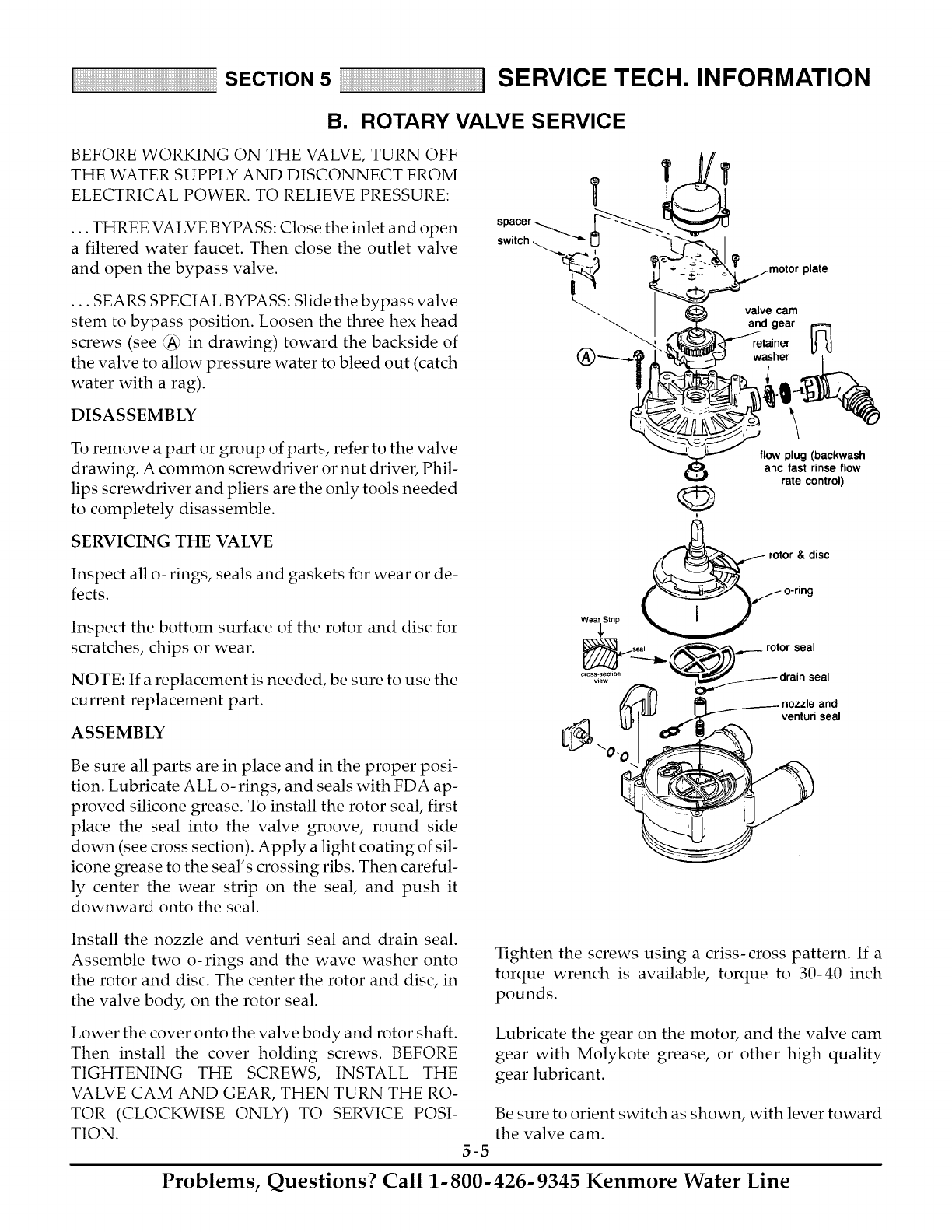
B. ROTARY VALVE SERVICE
BEFORE WORKING ON THE VALVE, TURN OFF
THE WATER SUPPLY AND DISCONNECT FROM
ELECTRICAL POWER. TO RELIEVE PRESSURE:
... THREE VALVE BYPASS: Close the inlet and open
a filtered water faucet. Then close the outlet valve
and open the bypass valve.
... SEARS SPECIAL BYPASS: Slide the bypass valve
stem to bypass position. Loosen the three hex head
screws (see (A_ in drawing) toward the backside of
the valve to allow pressure water to bleed out (catch
water with a rag).
DISASSEMBLY
To remove a part or group of parts, refer to the valve
drawing. A common screwdriver or nut driver, Phil-
lips screwdriver and pliers are the only tools needed
to completely disassemble.
8
t
\
flow plug (backwash
and fast rinse flow
rate control)
SERVICING THE VALVE
Inspect all o- rings, seals and gaskets for wear or de-
fects.
rotor & disc
Inspect the bottom surface of the rotor and disc for
scratches, chips or wear.
NOTE: If a replacement is needed, be sure to use the
current replacement part.
ASSEMBLY
Be sure all parts are in place and in the proper posi-
tion. Lubricate ALL o-rings, and seals with FDA ap-
proved silicone grease. To install the rotor seal, first
place the seal into the valve groove, round side
down (see cross section). Apply a light coating of sil-
icone grease to the seal's crossing ribs. Then careful-
ly center the wear strip on the seal, and push it
downward onto the seal.
venturi seal
Install the nozzle and venturi seal and drain seal.
Assemble two o-rings and the wave washer onto
the rotor and disc. The center the rotor and disc, in
the valve body, on the rotor seal.
Tighten the screws using a criss-cross pattern. If a
torque wrench is available, torque to 30-40 inch
pounds.
Lower the cover onto the valve body and rotor shaft.
Then install the cover holding screws. BEFORE
TIGHTENING THE SCREWS, INSTALL THE
VALVE CAM AND GEAR, THEN TURN THE RO-
TOR (CLOCKWISE ONLY) TO SERVICE POSI-
TION.
5-5
Lubricate the gear on the motor, and the valve cam
gear with Molykote grease, or other high quality
gear lubricant.
Be sure to orient switch as shown, with lever toward
the valve cam.
Problems, Questions? Call 1-800-426-9345 Kenmore Water Line
SECTION5 SERVICE TECH. INFORMATION
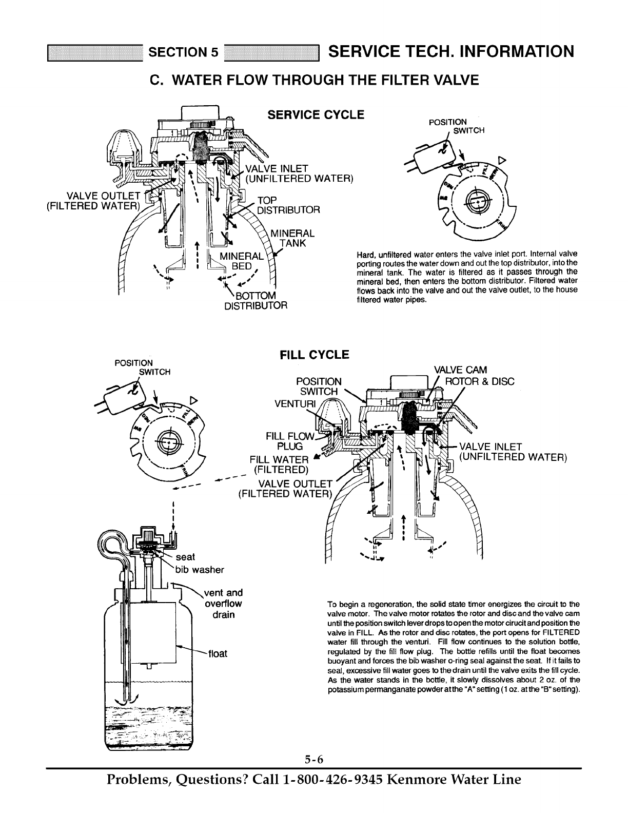
C. WATER FLOW THROUGH THE FILTER VALVE
VALVE OUTLET
(FILTERED WATER'
SERVICE CYCLE
,VALVE INLET
(UNFILTERED WATER)
TOP
DISTRIBUTOR
MINERAL
TANK
INERAL
BE ,
4!" 4.o"
kk,BOTTOM
DISTRIBUTOR
POSITION
SWlmCH
Hard, unfiltered water enters the valve inlet port. Internal valve
porting routes the water down and out the top distributor, into the
mineral tank. The water is filtered as it passes through the
mineral bed, then enters the bottom distributor. Filtered water
flows back into the valve and out the valve outlet, to the house
filtered water pipes.
POSITION
SWITCH
I
I
I
seat
FILL CYCLE
POSITION
SWITCH
VENTURI
washer
vent and
overflow
drain
FILL FLOW
PLUG
VALVE CAM
ROTOR & DISC
FILL WATER
(FILTERED)
""-- VALVE OUTLET
(FILTERED WATER
VALVE INLET
(UNFILTERED WATER)
To begin aregeneration, the solid state timer energizes the circuitto the
valve motor. The valve motor rotatesthe rotorand diseand thevalve cam
untilthe positionswitch leverdrops toopen the motorcirucitand position the
valve in FILL. As the rotorand disc rotates, the portopens for FILTERED
water fill through the venturi. Fill flow continues to the solution bottle,
regulated by the fill flow plug. The bo_e refills until the float becomes
buoyant and forces the bibwasher o-ring seal against the seat. If itfails to
seal, excessive fill water goes to the drain untilthe valve exits the fill cycle.
As the water stands in the bottle, it slowly dissolves about 2 oz. of the
potassiumpermanganate powder atthe "A" setting(1 oz. atthe "B" setting).
5-6
Problems, Questions? Call 1-800-426-9345 Kenmore Water Line
SECTION5 SERVICE TECH. INFORMATION
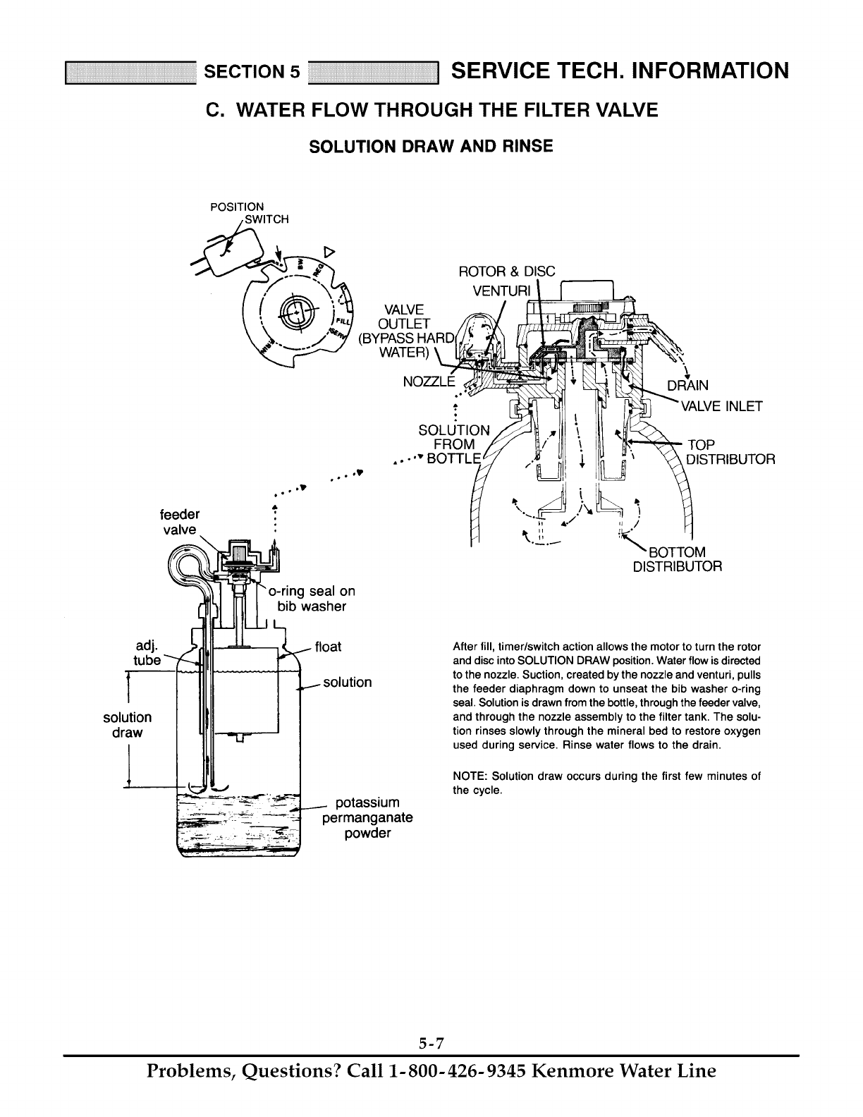
C. WATER FLOW THROUGH THE FILTER VALVE
SOLUTION DRAW AND RINSE
POSITION
adj.
solution
draw
feeder
valve
oot I_
w°° o_
seal on
bib washer
float
VALVE
OUTLET
(BYPASS
WATER)
NO77LE
ROTOR & DISC
VENTURI
.A
SOLUTION
\
DRAIN
INLET
UTOP
DISTRIBUTOR
,J /
rL_°
'_"_ BOTTOM
DISTRIBUTOR
potassium
permanganate
powder
After fill, timer/switch action allows the motor to turn the rotor
and disc into SOLUTION DRAW position. Water flow is directed
to the nozzle. Suction, created by the nozzle and venturi, pulls
the feeder diaphragm down to unseat the bib washer o-ring
seal. Solution is drawn from the bottle, through the feeder valve,
and through the nozzle assembly to the filter tank. The solu-
tion rinses slowly through the mineral bed to restore oxygen
used during service. Rinse water flows to the drain.
NOTE: Solution draw occurs during the first few minutes of
the cycle.
5-7
Problems, Questions? Call 1-800-426-9345 Kenmore Water Line

SECTION5 SERVICE TECH. INFORMATION
C. WATER FLOW THROUGH THE FILTER VALVE
BACKWASH CYCLE FAST RINSE CYCLE
POSITION POSITION
SWITCH
ROTOR &FLOW PLUG ROTOR & DISC
POSITION SWITCH
VALVE
INLET
OUTLET DISTRIBUTOR
_k_, . BOI-I'OM
DISTRIBUTOR
OUTLET
DRAIN
INLET
TOP
DISTRIBUTOR
....2.._ BOTTOM
DISTRIBUTOR
Switching action again allows the motor to turn the rotor & disc to place the
valve in BACKWASH, stopping water flow to the nozzle. Water is routed
down and out the bottom distributor, up through the bed, and out the top
distributorto the drain. The fast flow (controlled by a flow plug in the drain
fitting) flushes dirt, sediments, iron deposits, and remaining solution to the
drain.
During FAST RINSE, the rotor & disc is positioned so water flow enters the
mineral tank through the top distributor, and exits through the bottom
distributor, to the drain. The fast flow of water downward through the
mineral bed flushes any remaining solutionto the drain. The mineral bed is
packed and prepared for return to service.
The solid state timer again energizes the motor to return the valve to
As the valve rotates, the position switch lever drops to open the
circuit. The valve remains positioned in service until the timer initiates the
next regeneration.
5-8
Problems, Questions? Call 1-800-426-9345 Kenmore Water Line
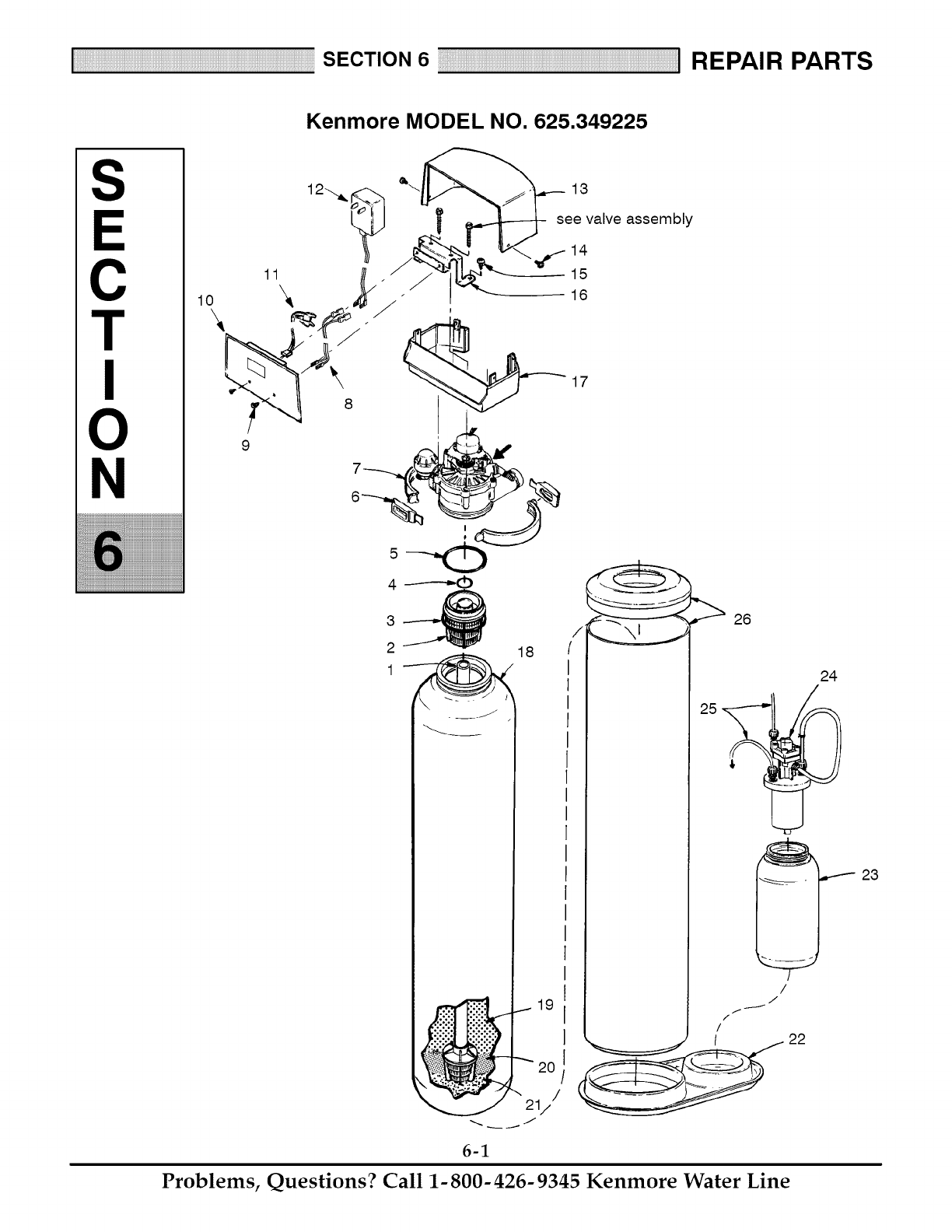
Kenmore MODEL NO. 625.349225
S
C
T
N
13
see valve assembly
14
15
16
4 __----_(b
2
_v
18
2O
J
(
24
/
23
/
J
f
/
/
6-1
Problems, Questions? Call 1-800-426-9345 Kenmore Water Line
Kenmore MODEL NO. 625.349225
KEY PART DESCRIPTION
NO. NO.
1 7105047 Rep'l Distributor
2 7088855 Top Distributor
3 7170270 O-Ring, 2-3/4 x 3
4 7170254 O-Ring, 13/16 x 1-1/16
5 7170296 O-Ring, 2-7/8 x 3-1/4
6 7088033 Clamp Retainer (2 req'd)
7 7176292 Clamp Section (2 req'd)
8 7128566 Power Cable Wire Harness
9 0900300 Screw, #4-40 x 1/4 (2 req'd)
10 7285677 Faceplate Timer
11 7259927 Wire Harness
12 7275907 Transformer, 24V- 1OVA
13 7144449 Top Cover
14 7103972 Screw, #8-18 x 7/16 (4 req'd)
15 0900291 Screw, #8-32 x 3/8 (2 req'd)
16 7288120 Cover Bracket
17 7146734 Bottom Cover
18 7092202 Mineral Tank
19 4015000 Mineral, 1 cu. ft.
20 0501783 Filter Sand, 10 Ibs.
36-----_
34-----_, ;
33"---" ='
3_,.,
29 _-------._
30 -'---_
29 _ f_
27
,".......... 43 ,/;-
45
KEY PART DESCRIPTION
NO. NO.
21 7124415 Gravel, 17 Ibs.
22 7010739 Tank Base
23 42-34417 Rep'l Bottle (Incl. 6 Ibs. Pot. Permanga-
nate)
24 7046968 Valve Asm (Incl. Key Nos. 27 - 47)
25 1124200 Tubing, 5/16 O.D. x 12 ft.
26 7092210 Shroud
4, 7026196 Base (styrofoam)
27 9001001 O-Ring, 3-7/8 x 4-1/8
28 7011816 Hose Adaptor (Includes Key No. 29)
29 1202600 Nut Ferrule (3 req'd)
30 7011785 Elbow (Includes Key No. 29)
31 7046942 Tube and Adaptor
32 7111519 O- Ring, 13/32 x 27/32
33 9000804 O-Ring, 7/8 x 1
34 0516403 Insert Seat
35 0504413 Diaphragm
36 7112735 Main Valve Stem
37 0507597 Diaphragm Cap
38 9006042 Screw, #10-14 x 1-1/4 Tapping (4
req'd)
39 7070666 Hose Clamp
40 7046633 Tubing (Adjustment)
41 1140800 Hose Adaptor (Machined)
42 7046641 Valve Body
43 9000601 Hose Adaptor (2 req'd)
44 1136300 Tubing
45 7046625 Tubing
46 7046683 Float
47 7047126 Pin
4, 7046950 Diaphragm Asm. (Incl. Key Nos. 31 - 36)
4, 7146611 Installation Manual
4, 7282679 Owner's Manual
Not illustrated
6-2
Problems, Questions? Call 1-800-426-9345 Kenmore Water Line

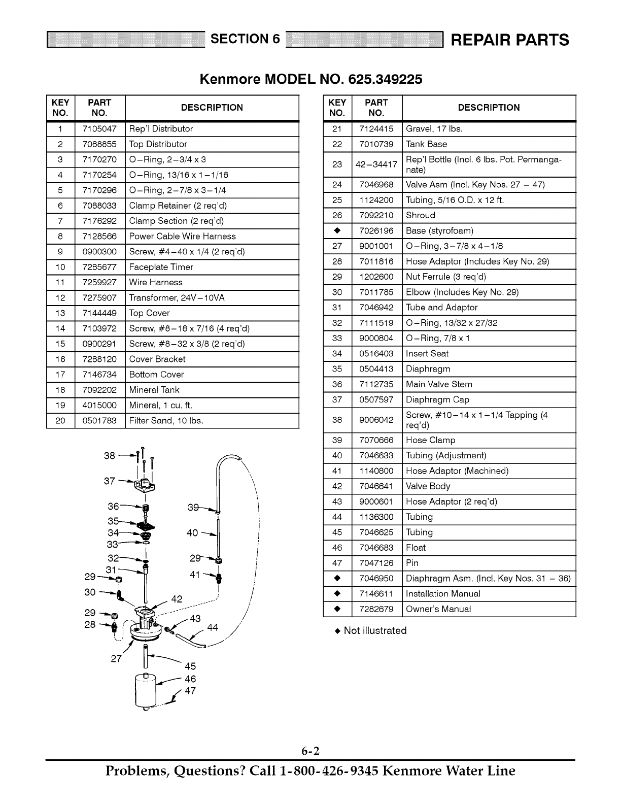
Kenmore MODEL NO. 625.349225
6
7
8
!
3O
21
2O 19
9 10 11
14
15
16
17
6-3
Problems, Questions? Call 1-800-426-9345 Kenmore Water Line

Kenmore MODEL NO. 625.349225
KEY PART KEY PART
DESCRIPTION
NO. NO. NO. NO.
1 7131755 Screw, #6-20 x 7/8 (2 req'd) 26 7146043
2 7281306 Motor 27 7167659
3 0900857 Screw, #6-20 x 3/8 (2 req'd) 28 7170262
4 7288112 Motor Plate 29 7199729
5 0503288 Bearing 30 7248706
6 7284964 Cam and Gear 31 7081764
7 7142942 Clip (Drain) 32 7129889
8 7030585 Retainer Washer 33 7092642
9 0509537 Flow Plug 34 7170204
10 7170327 O- Ring, 5/8 x 13/16 35 7134224
11 7141239 Drain Hose Adaptor 36 7170246
12 7116713 Clip (2 req'd) • 37 7199232
13 0507369 Installation Nut (2 req'd) [] 38 7082087
14 0507615 Installation Tube (2 req'd) [] 39 7170212
15 7170335 Washer (2 req'd) [] 40 7170238
16 2207800 Installation Adaptor (2 req'd) • 41 7085263
17 7170288 O-Ring, 15/16 x 1-3/16 (2 req'd) • 42 7074123
18 7082053 Valve Body 43 7077472
19 7170319 O-Ring, 1/4 x 3/8 (2 req'd) 44 7030713
20 7081201 Retainer (Nozzle & Ventud) 45 7117816
21 7081104 Nozzle & Venturi Housing 46 7070412
22 1202600 Nut Ferrule • 7085247
23 7089267 Tubing
24 1148800 Flow Plug, .3 gpm • 7111941
25 7114533 Nozzle & Venturi Gasket Kit 7129716
- 7204362 Gasket only
DESCRIPTION
Screen
Screen Support
O-Ring, 1-3/16 x 1-3/8
Cap
Ground Clamp •
Seat (Nozzle & Ventud)
Spring
Plug (Drain Seat)
O- Ring, 3/8 x 9/16
Rotor Seat
O-Ring, 3-3/8 x 3-5/8
Rotor & Disc
Wave Washer
O- Ring, 3/4 x 15/16
O- Ring, 7/16 x 5/8
Valve Cover
Screw, #1 O- 14 x 2 (5 req'd)
Expansion Pin
Switch
Spacer
Screw, #4-24 x 1-1/8
Nozzle & Venturi Asm. (Incl. Key Nos. 21
& 24 through 29)
Small Parts Bag (Incl. all items marked
with •)
Seat Kit (Incl. Key Nos. 31,34, 35, 36, 39
& 40)
Not illustrated.
[] Not included with filter - available from Sears Stock
No. 42-3441.
6-4
Problems, Questions? Call 1-800-426-9345 Kenmore Water Line

Your Home
For repair-in your home-of all major brand appliances,
lawn and garden equipment, or heating and cooling systems,
no matter who made it, no ma_er who sold it!
For the replacement pa_s, accessories and
owner's manuals that you need to do-it-yourself.
For Sears professional installation of home appliances
and items like garage door openers and water heaters.
1-800-4-MY-HOME ®
Call anytime, day or night (U.S.A. and Canada)
www.sea_.co m _'_+sea rs+ca
Our Home
For repair of carry-in items like vacuums, lawn equipment,
and electronics, call or go on-line for the location of your nearest
Sears Pa_s & Repair Center.
1-800-488-1222
Call an_ime, day or night (U.SA only)
www.sea rs,com
To purchase a protection agreement (U.S.A.)
or maintenance agreement (Canada) on a product serviced by Sears:
1-800-827-6655 (U.S.A,) 1-800-361-6665 (Canada)
Para pedir servicio de reparaci6n
a domicilio, y para ordenar piezas:
1-888-SU-HOGAR SM
(I-888-784-6427)
Au Canada pour servi_ en fran£ais:
t-800-LE-FOYER Mc
(1-800-533-6937)
www, sears.
!iIiiii:!iiiiiiiii_i_iii_iii_iii_iii_iii_iii_iii_iii_iii_iii_iii_iii_iii_iii_iii_iii_iii_iii_iii_iii_iii_iii_iii_iii_iii_iii_iii_iii_iii_iii_iii_iii_iii_iii_iii_iii_iii_iii_iii_iii_ii_ii
IN
® Reg_tered TrademaA /Trademark /_,_Sewice Mark of Seam, Roebuck and Co.
® Marca Registrada l_ Marca de F_bdca/s_ Marc;ade Servicio de Sears, Roebuck and Co_
_c Maque de commerce It_, Marque depos_e de Sea_, Roebuck and Co, @ Seam Roebuck and Co.
