Kenmore 79074503991 User Manual DUAL FUEL RANGE Manuals And Guides L0205072
KENMORE Range, Electric/Gas Manual L0205072 KENMORE Range, Electric/Gas Owner's Manual, KENMORE Range, Electric/Gas installation guides
User Manual: Kenmore 79074503991 79074503991 KENMORE DUAL FUEL RANGE - Manuals and Guides View the owners manual for your KENMORE DUAL FUEL RANGE #79074503991. Home:Kitchen Appliance Parts:Kenmore Parts:Kenmore DUAL FUEL RANGE Manual
Open the PDF directly: View PDF ![]() .
.
Page Count: 24
IMPORTANT: SAVE FOR LOCAL ELECTRICAL INSPECTOR'S USE.
READ AND SAVE THESE INSTRUCTIONS FOR FUTURE REFERENCE,
OBSERVE ALL GOVERNING CODES AND ORDINANCES.
If the information in this manual is not followed exactly, a fire or explosion may result
causing property damage, personal injury or death.
FOR YOUR SAFETY:
mDo not store or use gasoline or other flammable vapors and liquids in the vicinity of this or
any other appliance,
WHAT TO DO IF YOU SMELL GAS:
•Do not try to light any appliance,
•Do not touch any electrical switch; do not use any phone in your building,
•Immediately call your gas supplier from a neighbor's phone. Follow the gas supplier's
instructions,
•If you cannot reach your gas supplier, call the fire department,
Installation and service must be performed by a qualified installer, service agency or the gas
supplier.
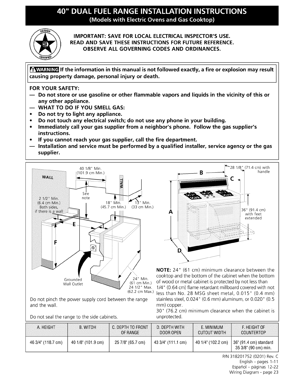
40 1/8" Min.
101.9 cm Min.)
Min.
(45.7 cm Min.) (33 cm Min.)
Grounded 24" Min.
Wall Outlet (61 cm Min.)
24 1/2" Max.
(62.2 cm Max.)
Do not pinch the power supply cord between the range
and the wall.
"9"28 1/8" (71.4 cm) with
handle
1
36" (91.4 cm)
with feet
extended
NOTE: 24" (61 cm) minimum clearance between the
cooktop and the bottom of the cabinet when the bottom
of wood or metal cabinet is protected by not lessthan
1/4" (0.64 cm) flame retardant millboard covered with not
less than No. 28 MSG sheet metal, 0.015" (0.4 mm)
stainless steel, 0.024" (0.6 mm) aluminum, or 0.020" (0.5
mm) copper.
30" (76.2 cm) minimum clearance when the cabinet is
Do not seal the range to the side cabinets, unprotected.
463/4"(118.7cm) 401/8"(101.9cm) 257/8"(65.7cm) 433/4"(111.1 cm) 401/4"(102.2cm) 36" (91.4 cm) standard
35 3/8" (90 cm) rain.
P/N 318201752 (0201) Rev. C
English - pages 1-11
EspaSol - p_iginas 12-22
Wiring Diagram - page 23
Important Notes to the Installer
1. Read all instructions contained in these installation
instructions before installing range.
2. Remove all packing material from the oven
compartments before connecting the electrical supply
to the range (see "Preparation", page 8).
3. Install the 4 shipping bolts from range
packaging as range leveling legs (see "Leveling the
Range", page 8).
4. Two anti-tip brackets MUST be removed from
lower back of range and MUST be installed (see
"Anti-Tip Bracket Installation", page 10).
5. Observe all governing codes and ordinances.
6. Besure to leave these instructions with the consumer.
Important Note to the Consumer
Keep these instructions with your owner's guide for future
reference.
IMPORTANT SAFETY
INSTRUCTIONS
Installation of this range must conform with local codes
or, in the absence of local codes, with the National Fuel
Gas Code ANSI Z223.1-1atest edition.
This range has been designed certified by the American
Gas Association. As with any appliance using gas and
generating heat, there are certain safety precautions you
should follow. You will find them in the Use and Care
Guide, read it carefully.
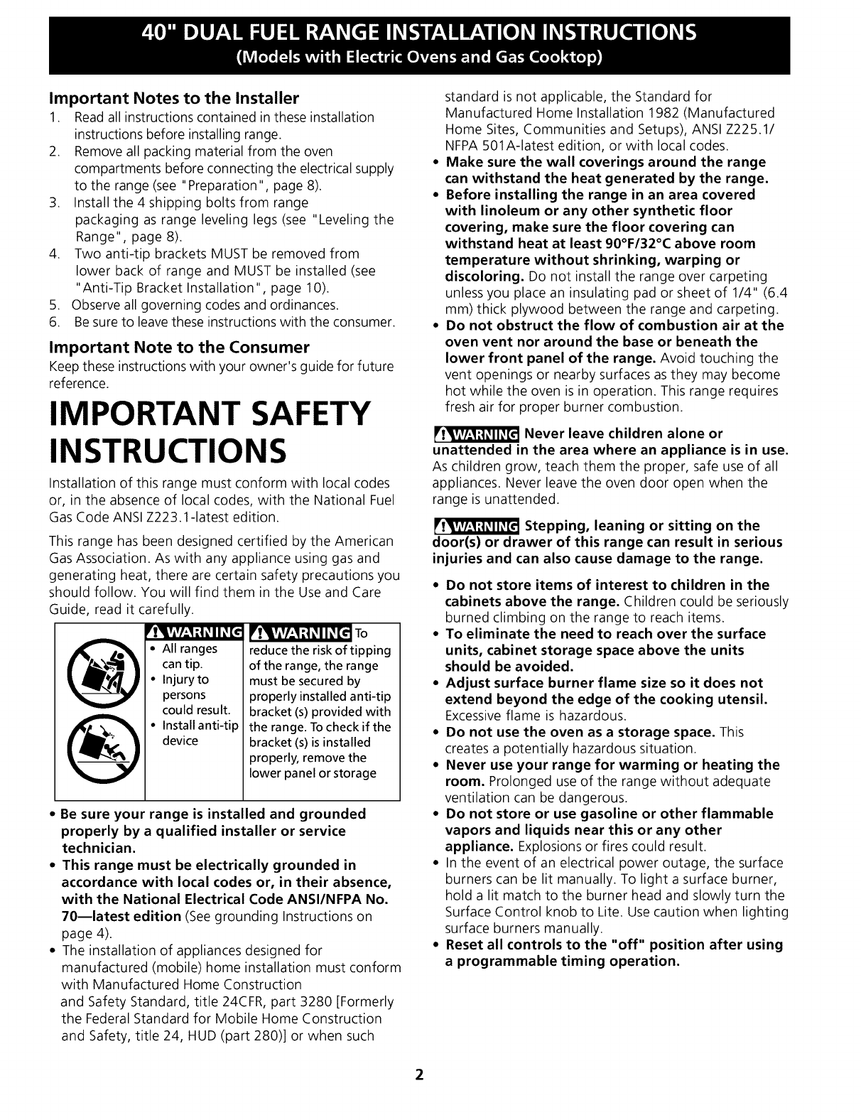
Ir!_lvAv/-*Ni! _I I_ Eel
•All ranges
can tip.
•Injury to
persons
could result.
• Install anti-tip
device
_!_kvlv/-'1 it _ II _[el To
reduce the risk of tipping
of the range, the range
must be secured by
properly installed anti-tip
bracket (s) provided with
the range. To check if the
bracket (s) is installed
properly, remove the
lower panel or storage
*Be sure your range is installed and grounded
properly by a qualified installer or service
technician.
*This range must be electrically grounded in
accordance with local codes or, in their absence,
with the National Electrical Code ANSI/NFPA No.
70--latest edition (See grounding Instructions on
page 4).
. The installation of appliances designed for
manufactured (mobile) home installation must conform
with Manufactured Home Construction
and Safety Standard, title 24CFR, part 3280 [Formerly
the Federal Standard for Mobile Home Construction
and Safety, title 24, Hun (part 280)] or when such
standard is not applicable, the Standard for
Manufactured Home Installation 1982 (Manufactured
Home Sites, Communities and Setups), ANSI Z225.1/
NFPA 501A-latest edition, or with local codes.
= Make sure the wall coverings around the range
can withstand the heat generated by the range.
= Before installing the range in an area covered
with linoleum or any other synthetic floor
covering, make sure the floor covering can
withstand heat at least 90°F/32°C above room
temperature without shrinking, warping or
discoloring. Do not install the range over carpeting
unless you place an insulating pad or sheet of 1/4" (6.4
mm) thick plywood between the range and carpeting.
= Do not obstruct the flow of combustion air at the
oven vent nor around the base or beneath the
lower front panel of the range. Avoid touching the
vent openings or nearby surfaces as they may become
hot while the oven is in operation. This range requires
fresh air for proper burner combustion.
Never leave children alone or
unattended in the area where an appliance is in use.
As children grow, teach them the proper, safe use of all
appliances. Never leave the oven door open when the
range is unattended.
Stepping, leaning or sitting on the
door(s) or drawer of this range can result in serious
injuries and can also cause damage to the range.
•Do not store items of interest to children in the
cabinets above the range. Children could be seriously
burned climbing on the range to reach items.
• To eliminate the need to reach over the surface
units, cabinet storage space above the units
should be avoided.
= Adjust surface burner flame size so it does not
extend beyond the edge of the cooking utensil.
Excessive flame is hazardous.
• Do not use the oven as a storage space. This
creates a potentially hazardous situation.
• Never use your range for warming or heating the
room. Prolonged use of the range without adequate
ventilation can be dangerous.
• Do not store or use gasoline or other flammable
vapors and liquids near this or any other
appliance. Explosions or fires could result.
• In the event of an electrical power outage, the surface
burners can be lit manually. To light a surface burner,
hold a lit match to the burner head and slowly turn the
Surface Control knob to Lite. Use caution when lighting
surface burners manually.
•Reset all controls to the "off" position after using
a programmable timing operation.
2
Power Supply Cord Kit
The user is responsible for connecting the power supply
cord to the connection block located behind the back
panel access cover.
This appliance may be connected by means of
permanent "hard wiring" (flexible armored or
nonmetallic shielded copper cable), or by means of a
power supply cord kit. Use only a power supply cord kit
rated at 125/250 volts minimum, 40 amperes minimum
and marked for use with ranges. See chart (below) for
cord kit connection opening size and rating information.
Cord must have either 3 or 4 conductors.
For mobile homes, new installations, recreational
vehicles, or areas where local codes do not permit
grounding through neutral, a 4 conductor power supply
cord kit rated at 125/250 volts minimum, 40 amperes
and marked for use with ranges should be used (see
Figure 4).
Terminals on end of wires must either be closed loop or
open-end spade lugs with upturned ends. Cord must
have strain relief clamp.
Risk of fire or electrical shock exists if
an incorrect size range cord kit is used, if the
Installation Instructions are not followed, or if the
strain relief bracket is discarded.
Range Connection Opening Size Chart
Refer to chart below for proper range connection opening size
and power supply cord kit ampere rating information. See serial
plate on range for kilowatt rating data.
Range Kilowatt Rating
(See Serial Plate on Range)
120/240 Volts
0 -16.5 kW
16.6-22.5 kW
120/208 Volts
0 -12.5 kW
12.6-18.5 kW
Minimum Diameter (inches) of Range
Cord kit Connection Opening
Ampere Direct
Rating Cord Kit Connection
40 Amp 1-3/8 in. 1-1/8 in.
50 Amp 1-3/8 in. 1-3/8 in.
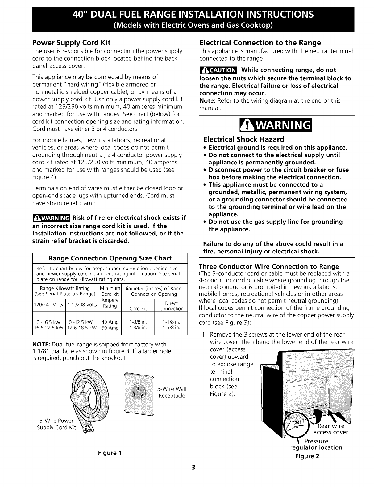
NOTE: Dual-fuel range is shipped from factory with
1 1/8" dia. hole as shown in figure 3. If a larger hole
is required, punch out the knockout.
3-Wire Power
Supply Cord Kit
3-Wire Wall
Receptacle
Figure 1
3
Electrical Connection to the Range
This appliance is manufactured with the neutral terminal
connected to the range.
While connecting range, do not
loosen the nuts which secure the terminal block to
the range. Electrical failure or loss of electrical
connection may occur.
Note: Refer to the wiring diagram at the end of this
manual.
Electrical Shock Hazard
•Electrical ground is required on this appliance.
•Do not connect to the electrical supply until
appliance is permanently grounded.
•Disconnect power to the circuit breaker or fuse
box before making the electrical connection.
•This appliance must be connected to a
grounded, metallic, permanent wiring system,
or a grounding connector should be connected
to the grounding terminal or wire lead on the
appliance.
•Do not use the gas supply line for grounding
the appliance.
Failure to do any of the above could result in a
fire, personal injury or electrical shock.
Three Conductor Wire Connection to Range
(The 3-conductor cord or cable must be replaced with a
4-conductor cord or cable where grounding through the
neutral conductor is prohibited in new installations,
mobile homes, recreational vehicles or in other areas
where local codes do not permit neutral grounding)
If local codes permit connection of the frame grounding
conductor to the neutral wire of the copper power supply
cord (see Figure 3):
.Remove the 3 screws at the lower end of the rear
wire cover, then bend the lower end of the rear wire
cover (access
cover) upward
to expose range
terminal
connection
block (see
Figure 2).
Rear wire
access cover
Pressure
regulator location
Figure 2
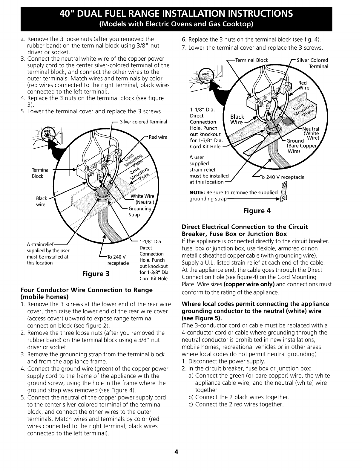
2. Remove the 3 loose nuts (after you removed the
rubber band) on the terminal block using 3/8" nut
driver or socket.
3. Connect the neutral white wire of the copper power
supply cord to the center silver-colored terminal of the
terminal block, and connect the other wires to the
outer terminals. Match wires and terminals by color
(red wires connected to the right terminal, black wires
connected to the left terminal).
4. Replace the 3 nuts on the terminal block (see figure
3).
5. Lower the terminal cover and replace the 3 screws.
Silver colored Terminal
wire
Terminal
Block
Black
wire
A strainrelief
supplied by the user
must be installed at
this location
I'o 240 V
receptacle
Figure 3
I-I/8" Dia.
Direct
Connection
Hole. Punch
out knockout
for I-3/8" Dia.
Cord Kit Hole
Four Conductor Wire Connection to Range
(mobile homes)
1. Remove the 3 screws at the lower end of the rear wire
cover, then raise the lower end of the rear wire cover
(access cover) upward to expose range terminal
connection block (see figure 2).
2. Remove the three loose nuts (after you removed the
rubber band) on the terminal block using a 3/8" nut
driver or socket.
3. Remove the grounding strap from the terminal block
and from the appliance frame.
4. Connect the ground wire (green) of the copper power
supply cord to the frame of the appliance with the
ground screw, using the hole in the frame where the
ground strap was removed (see Figure 4).
5. Connect the neutral of the copper power supply cord
to the center silver-colored terminal of the terminal
block, and connect the other wires to the outer
terminals. Match wires and terminals by color (red
wires connected to the right terminal, black wires
connected to the left terminal).
6. Replace the 3 nuts on the terminal block (see fig. 4).
7. Lower the terminal cover and replace the 3 screws.
Block Silver Colored
Terminal
1-1/8" Dia.
Direct
Connection
Hole. Punch
out knockout
for 1-3/8" Dia.
Cord Kit Hole
A user
supplied
strain-relief
must be installed 240 V receptacle
at this location d
NOTE: Be sure to remove the supplie
grounding strap
Figure 4
Direct Electrical Connection to the Circuit
Breaker, Fuse Box or Junction Box
If the appliance is connected directly to the circuit breaker,
fuse box or junction box, use flexible, armored or non
metallic sheathed copper cable (with grounding wire).
Supply a U.L listed strain-relief at each end of the cable.
At the appliance end, the cable goes through the Direct
Connection Hole (seefigure 4) on the Cord Mounting
Plate. Wire sizes (copper wire only) and connections must
conform to the rating of the appliance.
Where local codes permit connecting the appliance
grounding conductor to the neutral (white) wire
(see Figure 5).
(The 3-conductor cord or cable must be replaced with a
4-conductor cord or cable where grounding through the
neutral conductor is prohibited in new installations,
mobile homes, recreational vehicles or in other areas
where local codes do not permit neutral grounding)
1. Disconnect the power supply.
2. In the circuit breaker, fuse box or junction box:
a) Connect the green (or bare copper) wire, the white
appliance cable wire, and the neutral (white) wire
together.
b) Connect the 2 black wires together.
c) Connect the 2 red wires together.
4
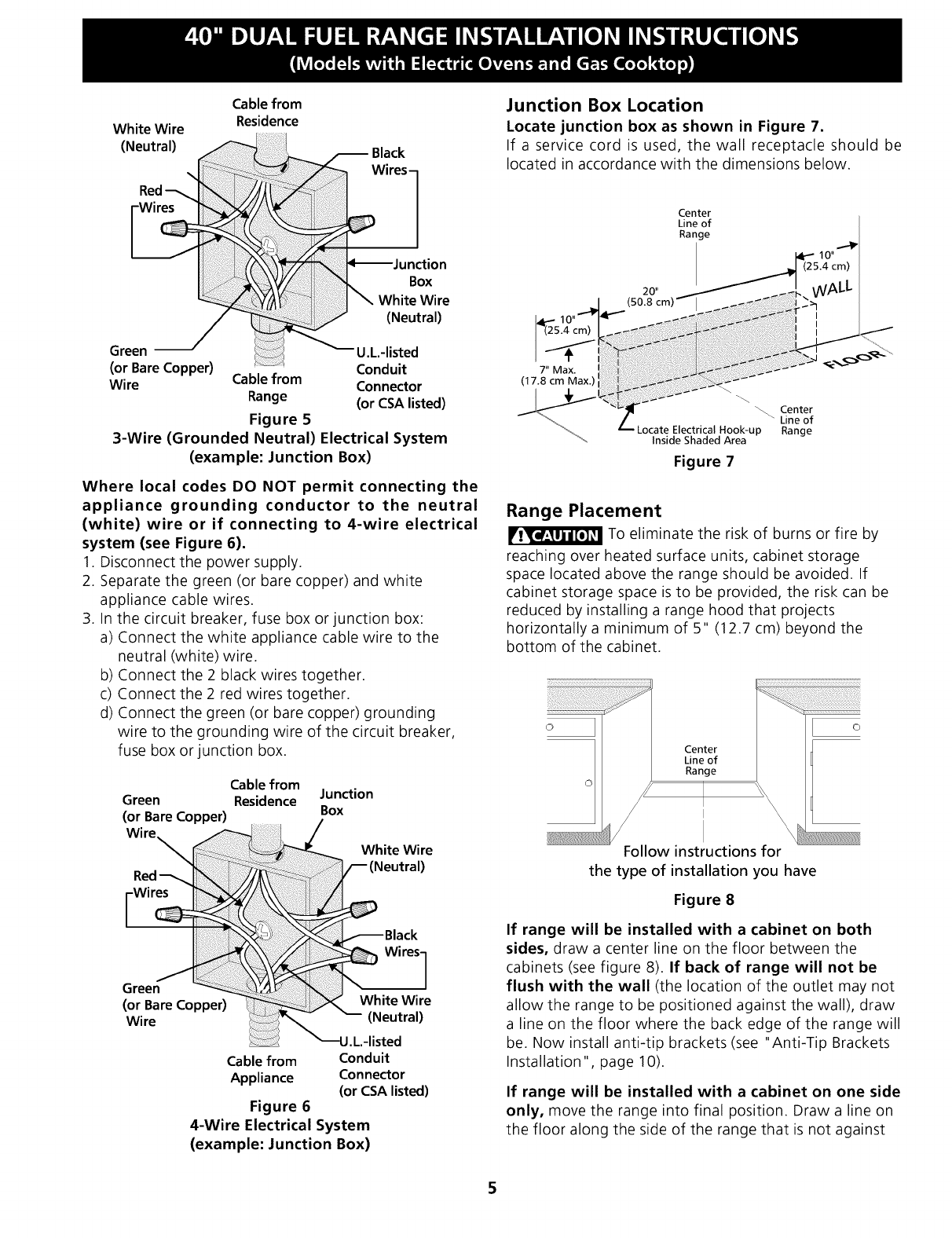
White Wire
(Neutral)
Cable from
Residence
Wires-
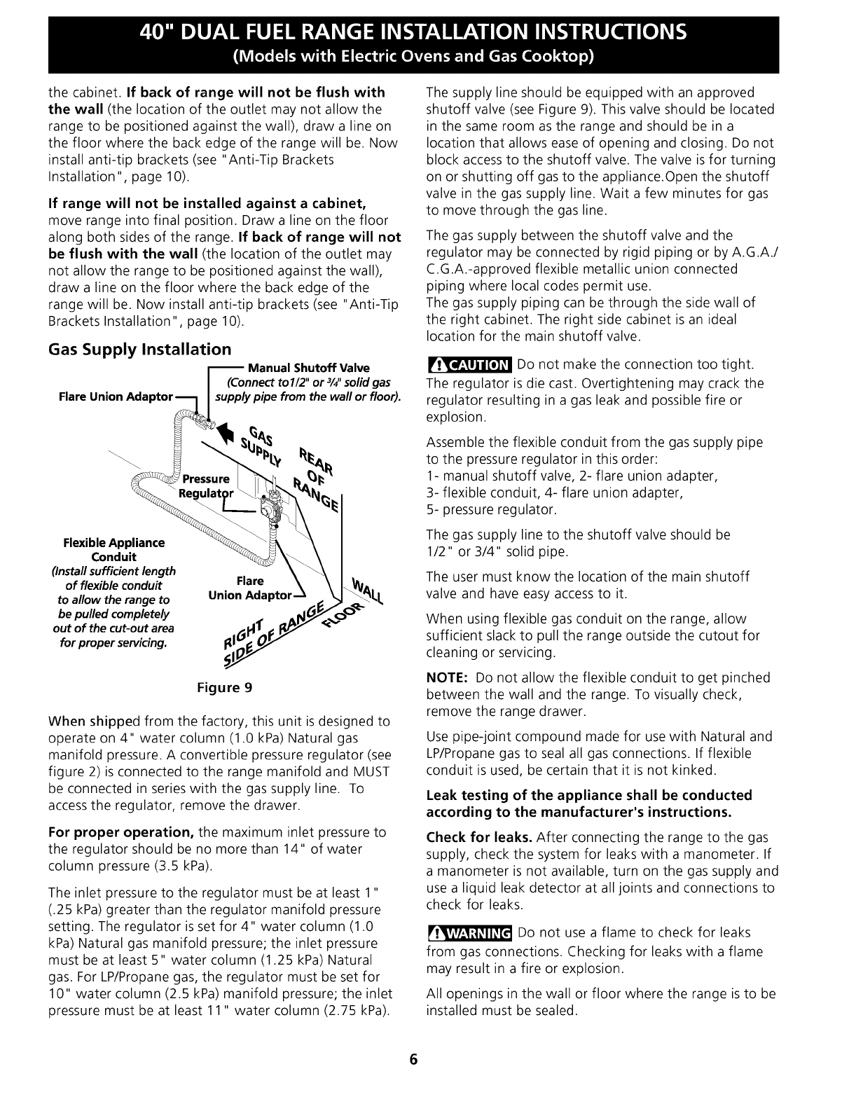
Junction Box Location
Locate junction box as shown in Figure 7.
If a service cord is used, the wall receptacle should be
located in accordance with the dimensions below.
Box
White Wire
(Neutral)
Green U.L.-listed
(or Bare Copper) Conduit
Wire Cable from Connector
Range (or CSA listed)
Figure 5
3-Wire (Grounded Neutral) Electrical System
(example: Junction Box)
Where local codes DO NOT permit connecting the
appliance grounding conductor to the neutral
(white) wire or if connecting to 4-wire electrical
system (see Figure 6).
1. Disconnect the power supply.
2. Separate the green (or bare copper) and white
appliance cable wires.
3. In the circuit breaker, fuse box or junction box:
a) Connect the white appliance cable wire to the
neutral (white) wire.
b) Connect the 2 black wires together.
c) Connect the 2 red wires together.
d) Connect the green (or bare copper) grounding
wire to the grounding wire of the circuit breaker,
fuse box or junction box.
Cable from
Green Residence Junction
(or Bare Copper) Box
Wire
White Wire
Green
(or Bare Copper)
Wire
White Wire
(Neutral)
Cable from Conduit
Appliance Connector
(or CSA listed)
Figure 6
4-Wire Electrical System
(example: Junction Box)
Center
Line of
Range
20" _ _ _.
m_) .41.... (50.8 cm) :
7" Max. : _ _
(17.8cmMax.)
"_ _ Center
/_ Line of
Locate Electrical Hook-up Range
Inside Shaded Area
Figure 7
J
Range Placement
To eliminate the risk of burns or fire by
reaching over heated surface units, cabinet storage
space located above the range should be avoided. If
cabinet storage space is to be provided, the risk can be
reduced by installing a range hood that projects
horizontally a minimum of 5" (12.7 cm) beyond the
bottom of the cabinet.
Follow instructions for
the type of installation you have
Figure 8
If range will be installed with a cabinet on both
sides, draw a center line on the floor between the
cabinets (see figure 8). If back of range will not be
flush with the wall (the location of the outlet may not
allow the range to be positioned against the wall), draw
a line on the floor where the back edge of the range will
be. Now install anti-tip brackets (see "Anti-Tip Brackets
Installation ", page 10).
If range will be installed with a cabinet on one side
only, move the range into final position. Draw a line on
the floor along the side of the range that is not against
thecabinet.If back of range will not be flush with
the wall (the location of the outlet may not allow the
range to be positioned against the wall), draw a line on
the floor where the back edge of the range will be. Now
install anti-tip brackets (see "Anti-Tip Brackets
Installation ", page 10).
If range will not be installed against a cabinet,
move range into final position. Draw a line on the floor
along both sides of the range. If back of range will not
be flush with the wall (the location of the outlet may
not allow the range to be positioned against the wall),
draw a line on the floor where the back edge of the
range will be. Now install anti-tip brackets (see "Anti-Tip
Brackets Installation", page 10).
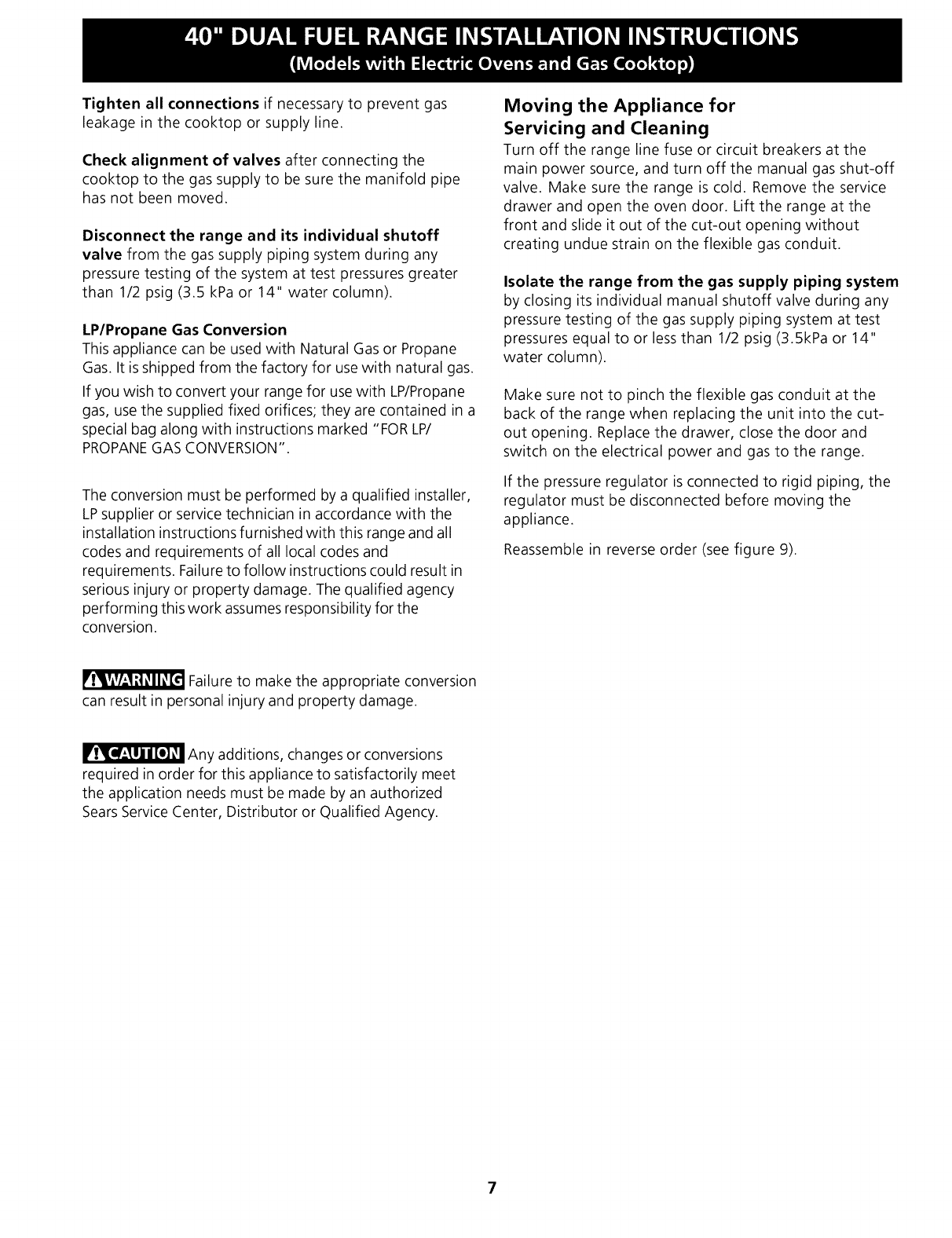
Gas Supply Installation
I Manual Shutoff,Valve
I(Connecttol/2 or¾ solidgas
Flare Union Adaptor-_] I supply pipe from the wall or floor).
c ,re . ure
Conduit \ I
(install sufficient length ° \ _\ I
of flexible conduit UnionFIAdaDtor _ _ _AI-
to allow the range to union Aclaptor -_ .€ _ _ I,
.K_Y c
be pulled completely .,4- A_._
outofthecut-outar a
forproperse,',,icing.
Figure 9
When shipped from the factory, this unit is designed to
operate on 4" water column (1.0 kPa) Natural gas
manifold pressure. A convertible pressure regulator (see
figure 2) is connected to the range manifold and MUST
be connected in series with the gas supply line. To
access the regulator, remove the drawer.
For proper operation, the maximum inlet pressure to
the regulator should be no more than 14" of water
column pressure (3.5 kPa).
The inlet pressure to the regulator must be at least 1"
(.25 kPa) greater than the regulator manifold pressure
setting. The regulator is set for 4" water column (1.0
kPa) Natural gas manifold pressure; the inlet pressure
must be at least 5" water column (1.25 kPa) Natural
gas. For LP/Propane gas, the regulator must be set for
10" water column (2.5 kPa) manifold pressure; the inlet
pressure must be at least 11 "water column (2.75 kPa).
The supply line should be equipped with an approved
shutoff valve (see Figure 9). This valve should be located
in the same room as the range and should be in a
location that allows ease of opening and closing. Do not
block access to the shutoff valve. The valve is for turning
on or shutting off gas to the appliance.Open the shutoff
valve in the gas supply line. Wait a few minutes for gas
to move through the gas line.
The gas supply between the shutoff valve and the
regulator may be connected by rigid piping or by A.G.A./
C.G.A.-approved flexible metallic union connected
piping where local codes permit use.
The gas supply piping can be through the side wall of
the right cabinet. The right side cabinet is an ideal
location for the main shutoff valve.
Do not make the connection too tight.
The regulator is die cast. Overtightening may crack the
regulator resulting in a gas leak and possible fire or
explosion.
Assemble the flexible conduit from the gas supply pipe
to the pressure regulator in this order:
1- manual shutoff valve, 2- flare union adapter,
3- flexible conduit, 4- flare union adapter,
5- pressure regulator.
The gas supply line to the shutoff valve should be
1/2" or 3/4" solid pipe.
The user must know the location of the main shutoff
valve and have easy access to it.
When using flexible gas conduit on the range, allow
sufficient slack to pull the range outside the cutout for
cleaning or servicing.
NOTE: Do not allow the flexible conduit to get pinched
between the wall and the range. To visually check,
remove the range drawer.
Use pipe-joint compound made for use with Natural and
LP/Propane gas to seal all gas connections. If flexible
conduit is used, be certain that it is not kinked.
Leak testing of the appliance shall be conducted
according to the manufacturer's instructions.
Check for leaks. After connecting the range to the gas
supply, check the system for leaks with a manometer. If
a manometer is not available, turn on the gas supply and
use a liquid leak detector at all joints and connections to
check for leaks.
Do not use a flame to check for leaks
from gas connections. Checking for leaks with a flame
may result in a fire or explosion.
All openings in the wall or floor where the range is to be
installed must be sealed.
6
Tighten all connections if necessary to prevent gas
leakage in the cooktop or supply line.
Check alignment of valves after connecting the
cooktop to the gas supply to be sure the manifold pipe
has not been moved.
Disconnect the range and its individual shutoff
valve from the gas supply piping system during any
pressure testing of the system at test pressures greater
than 1/2 psig (3.5 kPa or 14" water column).
LP/Propane Gas Conversion
This appliance can be used with Natural Gas or Propane
Gas. It is shipped from the factory for use with natural gas.
If you wish to convert your range for use with LP/Propane
gas, use the supplied fixed orifices; they are contained in a
special bag along with instructions marked "FOR LP/
PROPANEGAS CONVERSION".
The conversion must be performed by a qualified installer,
LPsupplier or service technician in accordance with the
installation instructions furnished with this range and all
codes and requirements of all local codes and
requirements. Failure to follow instructions could result in
serious injury or property damage. The qualified agency
performing this work assumes responsibility for the
conversion.
Moving the Appliance for
Servicing and Cleaning
Turn off the range line fuse or circuit breakers at the
main power source, and turn off the manual gas shut-off
valve. Make sure the range is cold. Remove the service
drawer and open the oven door. Lift the range at the
front and slide it out of the cut-out opening without
creating undue strain on the flexible gas conduit.
Isolate the range from the gas supply piping system
by closing its individual manual shutoff valve during any
pressure testing of the gas supply piping system at test
pressures equal to or less than 1/2 psig (3.5kPa or 14"
water column).
Make sure not to pinch the flexible gas conduit at the
back of the range when replacing the unit into the cut-
out opening. Replace the drawer, close the door and
switch on the electrical power and gas to the range.
If the pressure regulator is connected to rigid piping, the
regulator must be disconnected before moving the
appliance.
Reassemble in reverse order (see figure 9).
Failure to make the appropriate conversion
can result in personal injury and property damage.
Any additions, changes or conversions
required in order for this appliance to satisfactorily meet
the application needs must be made by an authorized
Sears Service Center, Distributor or Qualified Agency.
7
Range Installation
[Ir_'_TJ'i_J'_ When unpacking the range, do not
discard the 4 shipping bolts. These are to be replaced on
the unit for use as leveling legs and height adjustments.
NOTE:
1. The back of the range may be installed directly
against the wall.
2. To reduce possible scorching of vertical walls and to
minimize potential fire hazards under abnormal
surface unit use conditions such as high heat or no
pans and to conform to A.G.A. requirements, a
minimum of 2 1/2" (6.4 cm) spacing should be
provided on both sides of the cooktop.
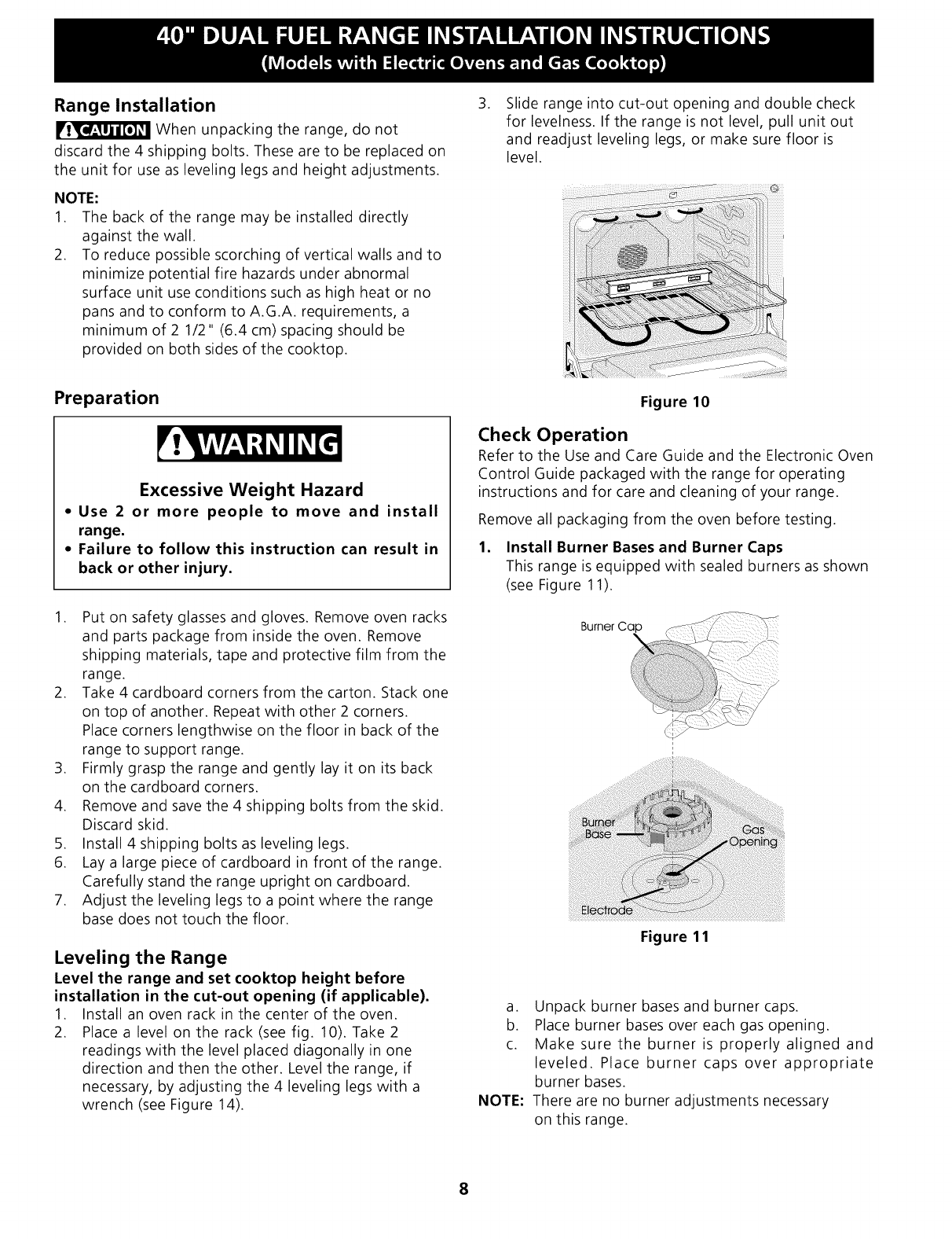
.Slide range into cut-out opening and double check
for levelness. If the range is not level, pull unit out
and readjust leveling legs, or make sure floor is
level.
Preparation
Excessive Weight Hazard
= Use 2 or more people to move and install
range.
= Failure to follow this instruction can result in
back or other injury.
1. Put on safety glasses and gloves. Remove oven racks
and parts package from inside the oven. Remove
shipping materials, tape and protective film from the
range.
2. Take 4 cardboard corners from the carton. Stack one
on top of another. Repeat with other 2 corners.
Place corners lengthwise on the floor in back of the
range to support range.
3. Firmly grasp the range and gently lay it on its back
on the cardboard corners.
4. Remove and save the 4 shipping bolts from the skid.
Discard skid.
5. Install 4 shipping bolts as leveling legs.
6. Lay a large piece of cardboard in front of the range.
Carefully stand the range upright on cardboard.
7. Adjust the leveling legs to a point where the range
base does not touch the floor.
Leveling the Range
Level the range and set cooktop height before
installation in the cut-out opening (if applicable).
1. Install an oven rack in the center of the oven.
2. Place a level on the rack (see fig. 10). Take 2
readings with the level placed diagonally in one
direction and then the other. Level the range, if
necessary, by adjusting the 4 leveling legs with a
wrench (see Figure 14).
Figure 10
Check Operation
Refer to the Use and Care Guide and the Electronic Oven
Control Guide packaged with the range for operating
instructions and for care and cleaning of your range.
Remove all packaging from the oven before testing.
1. Install Burner Bases and Burner Caps
This range is equipped with sealed burners as shown
(see Figure 11).
Burner Ca_
Figure 11
a. Unpack burner bases and burner caps.
b. Place burner bases over each gas opening.
c. Make sure the burner is properly aligned and
leveled. Place burner caps over appropriate
burner bases.
NOTE: There are no burner adjustments necessary
on this range.
8
.
.
.
Turn on Electrical Power and Open Main Shutoff
Gas Valve
Check the Igniters
Operation of electric igniters should be checked after
range and supply line connectors have been carefully
checked for leaks and range has been connected to
electric power. To check for proper lighting:
a. Push in and turn a surface burner knob to the
LITEposition. You will hear the igniter sparking.
b. The surface burner should light when gas is
available to the top burner. Each burner should
light within four (4) seconds in normal operation
after air has been purged from supply lines.
Visually check that burner has lit.
c. Once the burner lights, the control knob should
be rotated out of the LITEposition.
There are separate ignition devices for each burner.
Try each knob separately until all burner valves have
been checked.
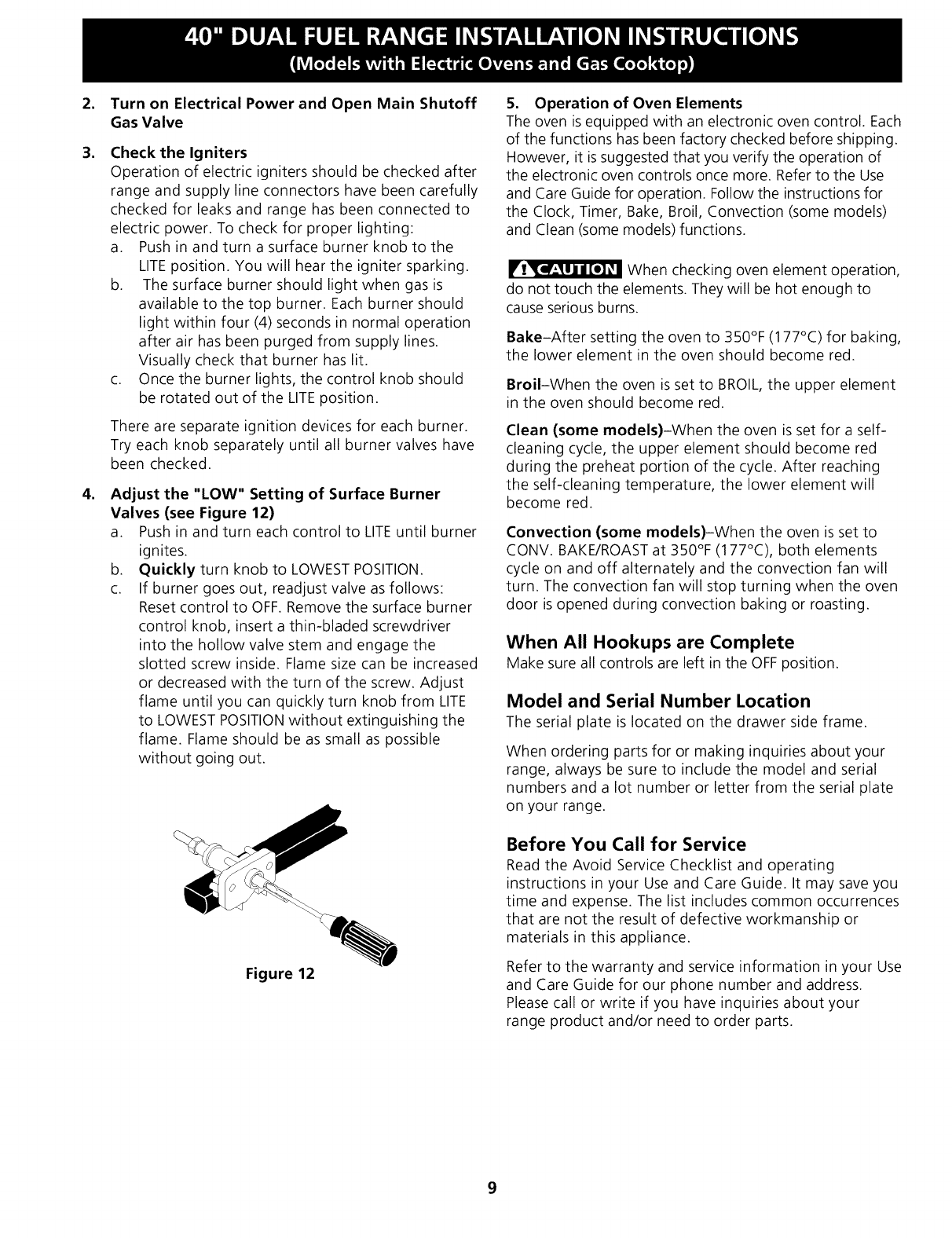
Adjust the "LOW" Setting of Surface Burner
Valves (see Figure 12)
a. Push in and turn each control to LITEuntil burner
ignites.
b. Quickly turn knob to LOWESTPOSITION.
c. If burner goes out, readjust valve as follows:
Reset control to OFF. Remove the surface burner
control knob, insert a thin-bladed screwdriver
into the hollow valve stem and engage the
slotted screw inside. Flame size can be increased
or decreased with the turn of the screw. Adjust
flame until you can quickly turn knob from LITE
to LOWEST POSITIONwithout extinguishing the
flame. Flame should be as small as possible
without going out.
Figure 12
5. Operation of Oven Elements
The oven is equipped with an electronic oven control. Each
of the functions has been factory checked before shipping.
However, it is suggested that you verify the operation of
the electronic oven controls once more. Refer to the Use
and Care Guide for operation. Follow the instructions for
the Clock, Timer, Bake, Broil, Convection (some models)
and Clean (some models) functions.
When checking oven element operation,
do not touch the elements. They will be hot enough to
cause serious burns.
Bake-After setting the oven to 350°F (177°C) for baking,
the lower element in the oven should become red.
Broil-When the oven is set to BROIL, the upper element
in the oven should become red.
Clean (some models)-When the oven is set for a self-
cleaning cycle, the upper element should become red
during the preheat portion of the cycle. After reaching
the self-cleaning temperature, the lower element will
become red.
Convection (some models)-When the oven is set to
CONV. BAKE/ROAST at 350°F (177°C), both elements
cycle on and off alternately and the convection fan will
turn. The convection fan will stop turning when the oven
door is opened during convection baking or roasting.
When All Hookups are Complete
Make sure all controls are left in the OFFposition.
Model and Serial Number Location
The serial plate is located on the drawer side frame.
When ordering parts for or making inquiries about your
range, always be sure to include the model and serial
numbers and a lot number or letter from the serial plate
on your range.
Before You Call for Service
Read the Avoid Service Checklist and operating
instructions in your Use and Care Guide. It may save you
time and expense. The list includes common occurrences
that are not the result of defective workmanship or
materials in this appliance.
Refer to the warranty and service information in your Use
and Care Guide for our phone number and address.
Please call or write if you have inquiries about your
range product and/or need to order parts.
9
Important Safety Warning
To reduce the risk of tipping of the range, the range
must be secured to the floor by properly installed anti-tip
brackets and screws packed with the range. Those parts
are located in a plastic bag in the oven. Failure to install
the anti-tip brackets will allow the range to tip over if
excessive weight is placed on an open door or if a child
climbs upon it. Serious injury might result from spilled
hot liquids or from the range itself.
Follow the instructions below to install the anti-tip
brackets.
If range is ever moved to a different location, the anti-tip
brackets must also be moved and installed with the
range. To check for proper installation, see step 5.
Tools Required:
5/16" (8 mm) Nutdriver or Flat Head Screwdriver
Adjustable Wrench
Electric Drill
3/16" (4.8 mm) Diameter Drill Bit
3/16" (4.8 mm) Diameter Masonry Drill Bit (if installing
in concrete)
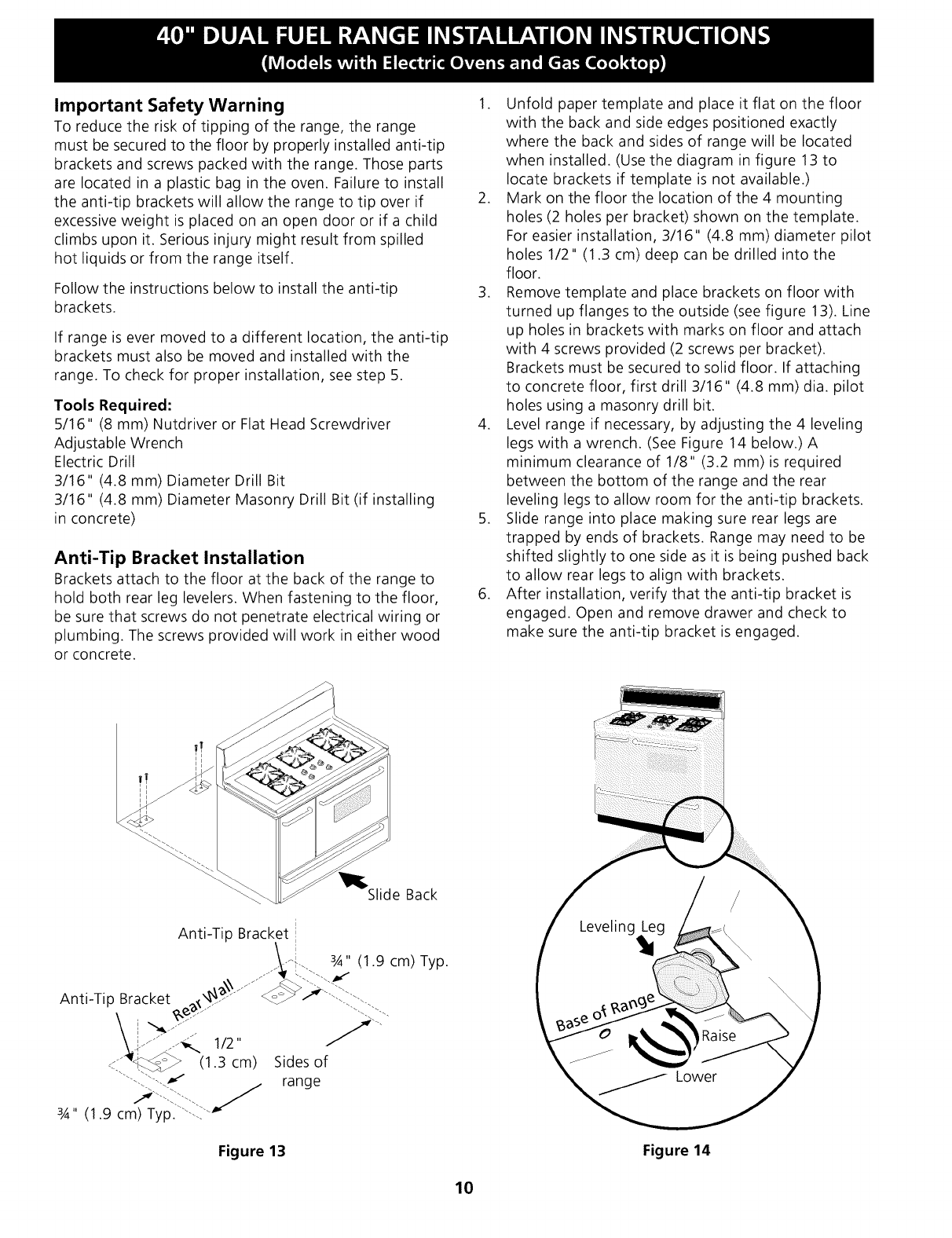
Anti-Tip Bracket Installation
Brackets attach to the floor at the back of the range to
hold both rear leg levelers. When fastening to the floor,
be sure that screws do not penetrate electrical wiring or
plumbing. The screws provided will work in either wood
or concrete.
1. Unfold paper template and place it flat on the floor
with the back and side edges positioned exactly
where the back and sides of range will be located
when installed. (Use the diagram in figure 13 to
locate brackets if template is not available.)
2. Mark on the floor the location of the 4 mounting
holes (2 holes per bracket) shown on the template.
For easier installation, 3/16" (4.8 mm) diameter pilot
holes 1/2" (1.3 cm) deep can be drilled into the
floor.
3. Remove template and place brackets on floor with
turned up flanges to the outside (see figure 13). Line
up holes in brackets with marks on floor and attach
with 4 screws provided (2 screws per bracket).
Brackets must be secured to solid floor. If attaching
to concrete floor, first drill 3/16" (4.8 mm) dia. pilot
holes using a masonry drill bit.
4. Level range if necessary, by adjusting the 4 leveling
legs with a wrench. (See Figure 14 below.) A
minimum clearance of 1/8" (3.2 mm) is required
between the bottom of the range and the rear
leveling legs to allow room for the anti-tip brackets.
5. Slide range into place making sure rear legs are
trapped by ends of brackets. Range may need to be
shifted slightly to one side as it is being pushed back
to allow rear legs to align with brackets.
6. After installation, verify that the anti-tip bracket is
engaged. Open and remove drawer and check to
make sure the anti-tip bracket is engaged.
_l_Slide Back
i
Anti-Tip Bracket !
i
Anti-Tip Bracket __
_..:_.l_ (1.3 cm)
3,_,, (1.9 cm) Typ."'--i_-_"
Sides of
range
Figure 13 Figure 14
10
NOTES:
11
IMPORTANTE: GUARDE ESTAS INSTRUCCIONES PARA USO DEL
INSPECTOR LOCAL DE ELECTRICIDAD.
LEA Y GUARDE ESTAS INSTRUCCIONES PARA REFERENCIA FUTURA.
OBSERVE CODIGOS TODO GOBERNANTES Y ORDENANZAS.
riT_J_m_lsi la informacion contenida en este manual no es seguida exactamente, puede
ocurrir un incendio o explosion causando da6os materiales, lesion personal o la muerte.
PARA SU SEGURIDAD:
mNo almacene ni utilice gasolina u otros vapores y liquidos inflamables en la proximidad de _ste
o de cualquier otro artefacto.
QUE DEBE HACER SI PERCIBE OLOR A GAS:
• No trate de encender ning_n artefacto.
• No toque ning_n interruptor el_ctrico; no use ning_n tel_fono en su edificio.
• Llame a su proveedor de gas desde el tel_fono de un vecino. Siga las instrucciones del
proveedor de gas.
• Si no Iogra comunicarse con su proveedor de gas, Ilame al departamento de bomberos.
La instalacion y el servicio de mantenimiento deben ser efectuados por un instalador calificado,
la agencia de servicio o el proveedor de gas.
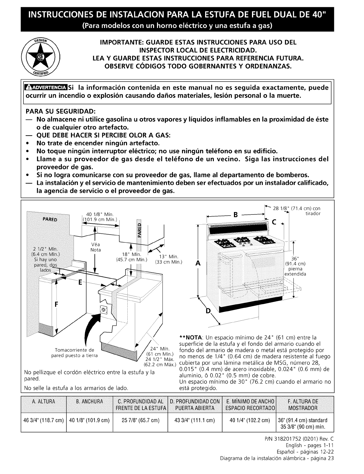
'28 1/8" (71.4 cm) con40 1/8" Min. B-tirador
101.9 cm Min.)
13" Min. 36"
(45.7 cm Min.) (33 cm Min.) A(91.4 cm)
pierna
extendida
Tomacorriente de 24" Min.
pared puesto a tierra (61 cm Min.)
24 1/2" M_tx.
(62.2 cm M_tx.)
No pellizque el cordon electrico entre la estufa y la
pared.
No selle la estufa a los armarios de lado.
463/4"(118.7cm) 401/8"(101.9cm) 257/8"(65.7cm) 433/4"(111.1 cm)
**NOTA: Un espacio mfnimo de 24" (61 cm) entre la
superficie de la estufa y el fondo del armario cuando el
fondo del armario de madera o metal est,1 protegido por
no menos de 1/4" (0.64 cm) de madera resistente al fuego
cubierta por una I_imina met_ilica de MSG, n0mero 28,
0.015" (0.4 mm) de acero inoxidable, 0.024" (0.6 mm) de
aluminio, 6 0.02" (0.5 mm) de cobre.
Un espacio mfnimo de 30" (76.2 cm) cuando el armario no
est,1 protegido.
40 1/4" (102.2 cm) 36" (91.4 cm) standard
35 3/8" (90 cm) min.
P/N 318201752 (0201) Rev.C
English - pages 1-11
Espa_ol - p_iginas 12-22
Diagrama de la instalaciOn al_imbrica - p_igina 23
Notas importantes para el Instalador
1. Lea todas las instrucciones contenidas en este manual
antes de instalar la estufa.
2. Saque todo el material usado en el embalaje del
compartimiento del horno antes de conectar el
suministro el_ctrico a la estufa.
3. Guarde los 4 pernos del empaque de la estufa
para usarlos como patas niveladoras.
4. Dos soportes antivuelco DEBEN quitarse de la
parte de inferior trasera de la estufa y DEBEN ser
instalados. Para detalles, vea instrucciones en la
p_gina 10.
5. Observe todos los c6digos y reglamentos pertinentes.
6. Deje estas instrucciones con el comprador.
Nota Importante para el Consumidor
Conserve estas instrucciones y el Manual del Usuario para
referencia futura.
IMPORTANTES
INSTRUCCIONES DE
SEGURIDAD
Instalaci6n de esta estufa debe cumplir con todos los
c6digos locales, o en ausencia de c6digos locales con el
C6digo Nacional de Gas Combustible ANSI Z223.1--
01tima edici6n.
El dise_o de esta estufa ha sido certificado por la
Asociaci6n de Gas Americana. En _ste como en
cualquier otro artefacto que use gas y genere calor, hay
ciertas precauciones de seguridad que usted debe seguir.
Estas ser_n encontradas en el Manual del Usuario, I_alo
cuidadosamente.
•Asegdrese de que la estufa sea instalada y
conectada a tierra en forma apropiada por un
instalador calificado o por un tdcnico.
•Esta estufa debe ser eldctricamente puesta a
tierra de acuerdo con los c6digos locales, o en su
ausencia, con el C6digo Eldctrico Nacional ANSI/
NFPA No. 70, dltima edici6n.
@• Todas las
estuffas
pueden
volcarse.
• Esto podria
resultar en
lesiones
personales.
• Instale el
dispositivo
antivuelcos que
se ha
empacado
junto con esta
estufa.
Para reducir el riesgo de
que se vuelque la estufa,
hay que asegurarla
adecuadamente
colocandole Los soportes
antivuelco que se
proporcionan. Para
comprobar si estos estan
instalados y apretados en
su lugar como se debe, ase
el borde trasero superior de
la estufa y cuidadosamente
inclinela hacia
adelante para asegurar
que la estufa se ancle.
• La instalaci6n de aparatos dise_ados para instalaci6n
en casas prefabricadas (m6viles) debe conformar con
el Manufactured Home Construction and Safety
Standard, t[tulo 24CFR, parte 3280 [Anteriormente el
Federal Standard for Mobil Home Construction and
Safety, t[tulo 24, HUD (parte 280)] o cuando tal
est_ndar no se aplica, el Standard for Manufactured
Home Installation 1982 (Manufactured Home sites,
Communities and Setups), ANSI Z225.1/NFPA 501A-
edici6n m_s reciente, o con los c6digos locales.
•Asegt_rese de que el material que recubre las
paredes alrededor de la estufa, pueda resistir el
calor generado por la estufa.
•Antes de instalar la estufa en un _rea cuyo piso
este recubierto con lin61eo u otro tipo de piso
sint_tico, asegt_rese de que _stos puedan resistir
una temperatura de por Io menos 90°F sobre la
temperatura ambiental sin provocar
encogimiento, deformaci6n o decoloraci6n. No
instale la estufa sobre una alfombra al menos que
coloque una plancha de material aislante de por Io
menos 1/4 pulgada, entre la estufa y la alfombra.
•No obstruya el flujo del aire de combusti6n en la
ventilaci6n del horno ni tampoco alrededor de la
base o debajo del panel inferior delantero de la
estufa. Evitetocarlasaberturaso_reascercanasde
la ventilaci6n, ya que pueden estar muy calientes
duranteelfuncionamientodel horno. Laestufa
requiere aire fresco para la combusti6n apropiada de
los quemadores.
Nunca deje ni_os solos o
desatendidos en un _rea donde un artefacto est_
siendo usado. A medida que los ni_os crecen,
ens_eles el uso apropiado y de seguridad para todos los
artefactos. Nunca dejela puerta del hornoabierta
cuando la estufa est_ desatendida.
No se pare, apoye o siente en las
puertas o cajones de esta estufa pues puede
resultar en serias lesiones y puede tambi_n causar
da_o a la estufa.
•No almacene articulos que puedan interesar a los
ni_os en los gabinetes sobre la estufa. Los niEos
pueden quemarse seriamente tratando de trepar a la
estufa para alcanzar estos art[culos.
•Los gabinetes de almacenamiento sobre la estufa
deben ser evitados, para eliminar la necesidad de
tener que pasar sobre los elementos superiores de
la estufa para Ilegar a ellos.
•Ajuste el tama_o de la llama de los quemadores
superiores de tal manera que _sta no sobrepase el
borde de los utensilios de cocinar. La llama
excesiva es peligrosa.
•No use el horno como espacio de almacenaje. Esto
crear_ una situaci6n potencialmente peligrosa.
•Nunca use la estufa para calentar el cuarto. El uso
prolongado de la estufa sin la adecuada ventilaci6n
puede resultar peligroso.
13
• No almacene ni utilice gasolina u otros vapores y
liquidos inflamables en la proximidad de dste o
de cualquier otro artefacto eldctrico. Puede
provocar incendio o explosi6n.
• En caso de una interrupti6n del servicio el_ctrico, es
pasible de encender los quemadores de superficie a
mano. Para encender un quemador de suoerficie,
acerque un f6sforo encendido del cabezal del
quemador, y gire delicadamente el bot6n de control de
superficie a LITE (encendido). Tener cuidado al
encender los quemadores a mano.
•Ajuste todos los controles a la posici6n "OFF" (apagada)
despuds de haber hecho una operacibn con tiempo
programado.
Juego de Cordbn Eldctrico
El consumidor tiene la responsabilidad de conectar el cord6n
el_ctrico al bloque de conexi6n ubicado detr_is de la cubierta
de acceso del panel trasero.
Este artefacto puede ser conectado mediante "cableado
rigido" permanente (un cable fexible escudido o un cable de
cobre escudido no met_ilico) o un "juego de cord6n
el_ctrico". Se usar_i solamente un juego de cord6n el_ctrico
para 125/250 voltios minimo, 40 amperios minimo y marcado
para uso con estufas. Eljuego de cord6n el_ctrico debe tener
3 o 4 conductores.
Para las casas sobre ruedas, las nuevas instalaciones, en los
vehiculos de recreaci6n o en las _ireas donde los c6digos
locales no permiten la conexi6n del conductor a tierra al
neutro, un ensamblaje de suministro el_ctrico de 4
conductores para estufas, clasificado a 125/250 voltios
minimo, 40 amperios minimo, debe de ser utilizado (vea
Figura 4).
Los terminales en las puntas de los alambres deben ser de
circuito cerrado o de orejeta de pala punta abierta y con las
puntas vueltas hacia arriba. El cord6n debe tener un anclaje
del cable.
Puede ocurrir riesgo de incendio o
choque el_ctrico si se usa un juego de cord6n de estufa de
tama_o incorrecto, si las instrucciones de instalaci6n no
son seguidas o si no se usa el anclaje del cable.
Tabla de tama_o de abertura de conexibn de cocina
Referirse a la tabla de arriba para el tama_o de abertura de
connexidn de cocina adecuada, y la informaci6n sobre el regimen
de amperios del ensamblaje de corddn de suministro electrico.
Vea la placa de serie de la
cocina para informaci6n
sobre el regimen de
kilovatio.
120/240 Volts 120/208 Volts
Minimo
regimen de
amperios
de
ensamblaje
del cord6n
0-16.5 Kw 0-12.5 Kw 40 Amp
16.6-22.5 Kw 12.6-18.5 Kw 50 Amp
Diametro (pulgadas) de
abierta de conexi6n de
cocina.
Dimensi6n Conexi6n
agujero directo
Connexi6n
1 3/8 pulg 1 1/8 pulg
1 3/8 pulg 1 3/8 pulg
NOTA: La estufa bi-energi_i viene de f_ibrica preparada para
funcionar con un hueco de 1 1/8" de diametro come se muestra
en la figura 3. En caso de necesitarse un hueco m_isgrande retire
la cubierta.
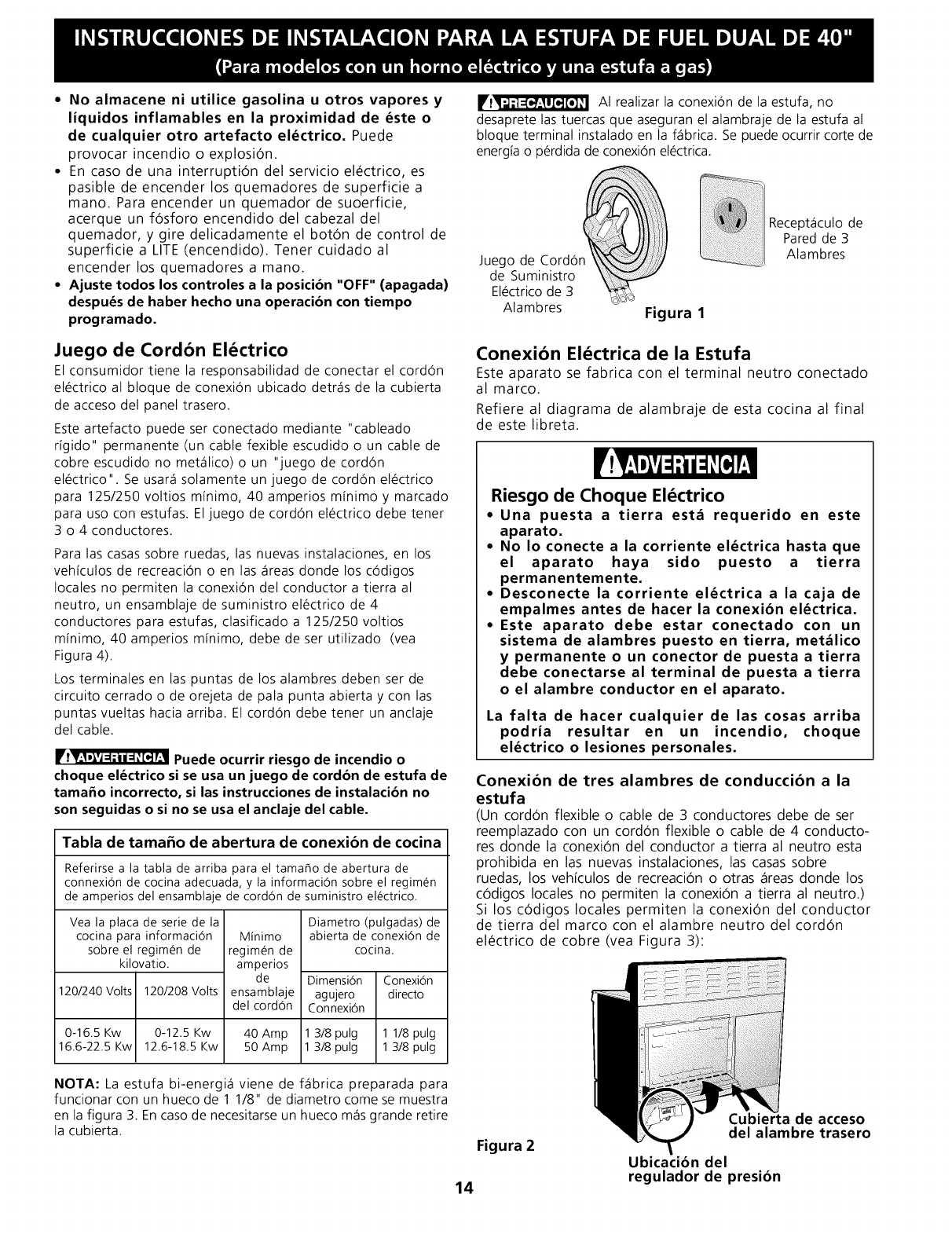
r13[_'_"=_'_ AI realizar la conexi6n de la estufa, no
desaprete las tuercas que aseguran el alambraje de la estufa al
bloque terminal instalado en la f_ibrica. Se puede ocurrir corte de
energia o p_rdida de conexi6n el_ctrica.
_ _Recept_iculo de
Pared de 3
Juego de Cord6n Alambres
de Suministro
El_ctrico de 3
Alambres Figura 1
Conexibn El_ctrica de la Estufa
Este aparato se fabrica con el terminal neutro conectado
al marco.
Refiere al diagrama de alambraje de esta cocina al final
de este libreta.
Riesgo de Choque El_ctrico
•Una puesta a tierra est& requerido en este
aparato.
No Io conecte a la corriente el_ctrica hasta que
el aparato haya sido puesto a tierra
permanentemente.
Desconecte la corriente el_ctrica a la caja de
empalmes antes de hacer la conexibn el_ctrica.
Este aparato debe estar conectado con un
sistema de alambres puesto en tierra, met&lico
y permanente o un conector de puesta a tierra
debe conectarse al terminal de puesta a tierra
o el alambre conductor en el aparato.
La falta de hacer cualquier de las cosas arriba
podria resultar en un incendio, choque
el_ctrico o lesiones personales.
Conexibn de tres alambres de conduccibn a la
estufa
(Un cord6n flexible o cable de 3 conductores debe de ser
reemplazado con un cord6n flexible o cable de 4 conducto-
res donde la conexi6n del conductor a tierra al neutro esta
prohibida en las nuevas instalaciones, las casas sobre
ruedas, los veh[culos de recreaci6n o otras _ireas donde los
c6digos locales no permiten la conexi6n a tierra al neutro.)
Si los c6digos locales permiten la conexi6n del conductor
de tierra del marco con el alambre neutro del cord6n
el_ctrico de cobre (vea Figura 3):
Figura 2
Cubiel ide acceso
del alambre trasero
Ubicacibn del
regulador de presibn
14
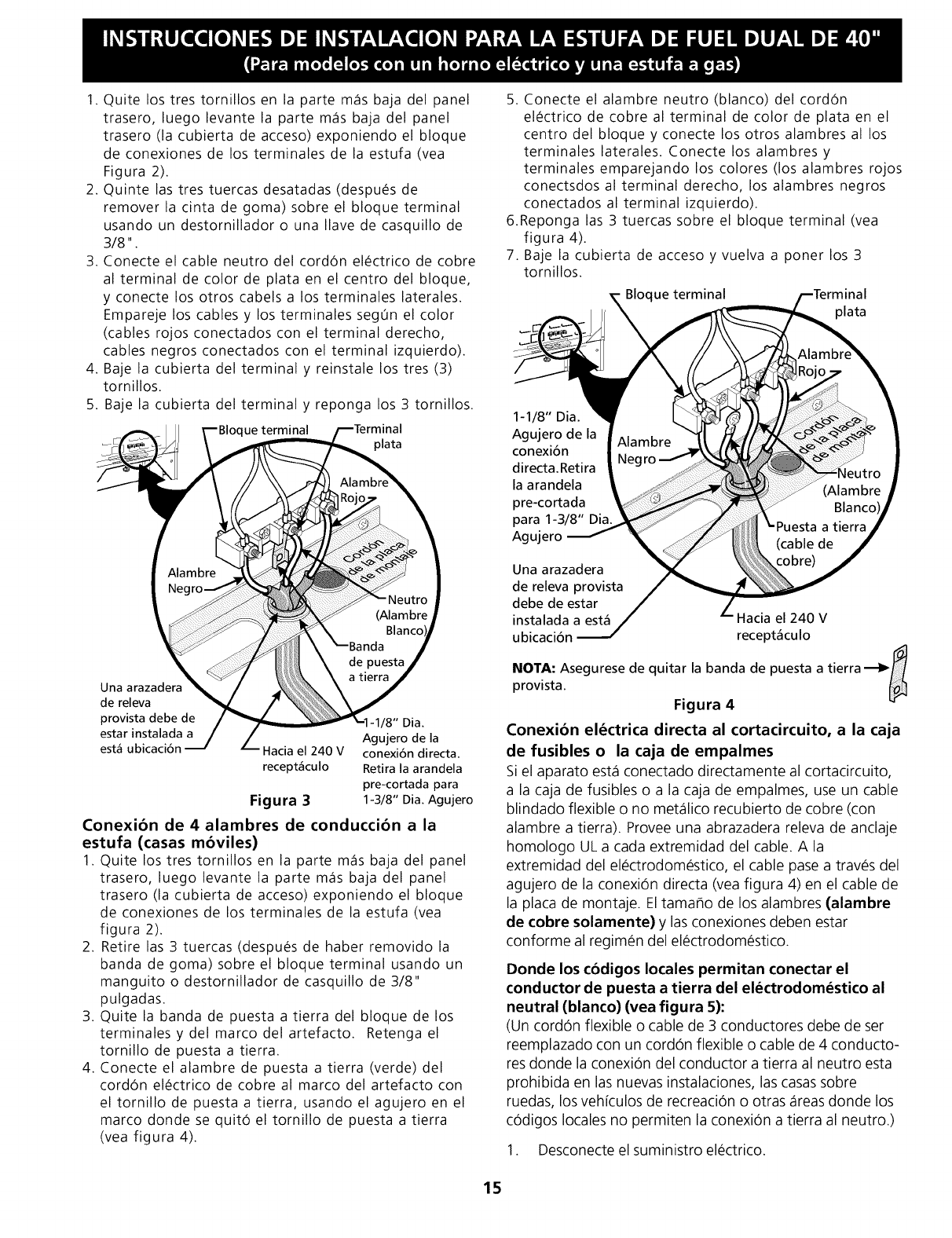
1. Quite los tres tornillos en la parte m_s baja del panel
trasero, luego levante la parte m_s baja del panel
trasero (la cubierta de acceso) exponiendo el bloque
de conexiones de los terminales de la estufa (vea
Figura 2).
2. Quinte las tres tuercas desatadas (despu_s de
remover la cinta de goma) sobre el bloque terminal
usando un destornillador o una Ilave de casquillo de
3/8".
3. Conecte el cable neutro del cord6n el_ctrico de cobre
al terminal de color de plata en el centro del bloque,
y conecte los otros cabels a los terminales laterales.
Empareje los cables y los terminales segOn el color
(cables rojos conectados con el terminal derecho,
cables negros conectados con el terminal izquierdo).
4. Baje la cubierta del terminal y reinstale los tres (3)
tornillos.
5. Baje la cubierta del terminal y reponga los 3 tornillos.
ue terminal
Una arazadera
de releva
provista debe de
estar instalada a
est_ ubicaci6n
/8" Dia.
Agujero de la
Hacia el 240 V conexi6n directa.
recept_culo Retira la arandela
pre-cortada para
Figura 31-3/8" Dia. Agujero
Conexi6n de 4 alambres de conducci6n a la
estufa (casas m6viles)
1. Quite los tres tornillos en la parte m_s baja del panel
trasero, luego levante la parte m_s baja del panel
trasero (la cubierta de acceso) exponiendo el bloque
de conexiones de los terminales de la estufa (vea
figura 2).
2. Retire las 3 tuercas (despu_s de haber removido la
banda de goma) sobre el bloque terminal usando un
manguito o destornillador de casquillo de 3/8"
pulgadas.
3. Quite la banda de puesta a tierra del bloque de los
terminalesydel marcodelartefacto. Retenga el
tornillo de puesta a tierra.
4. Conecte el alambre de puesta a tierra (verde) del
cord6n el_ctrico de cobre al marco del artefacto con
el tornillo de puesta a tierra, usando el agujero en el
marco donde se quit6 el tornillo de puesta a tierra
(vea figura 4).
5. Conecte el alambre neutro (blanco) del cord6n
el_ctrico de cobre al terminal de color de plata en el
centro del bloque y conecte los otros alambres al los
terminales laterales. Conecte los alambres y
terminales emparejando los colores (los alambres rojos
conectsdos al terminal derecho, los alambres negros
conectados al terminal izquierdo).
6.Reponga las 3 tuercas sobre el bloque terminal (vea
figura 4).
7. Baje la cubierta de acceso y vuelva a poner los 3
tornillos.
Bloque terminal
_lata
1-1/8" Dia.
Agujero de la
conexi6n
directa.Retira
la arandela
pre-cortada
para 1-3/8" Dia.
Agujero
Una arazadera
de releva provista
debe de estar
instalada a est_ Hacia el 240 V
ubicaci6n recept_culo
NOTA: Asegurese de quitar la banda de puesta a tierra _fl
provista.
Figura 4
Conexi6n el_ctrica directa al cortacircuito, a la caja
de fusibles o la caja de empalmes
Si el aparato est_ conectado directamente al cortacircuito,
a la caja de fusibles o a la caja de empalmes, use un cable
blindado flexible o no met_lico recubierto de cobre (con
alambre a tierra). Provee una abrazadera releva de anclaje
homologo UL a cada extremidad del cable. A la
extremidad del el_ctrodom_stico, el cable pase a trav_s del
agujero de la conexi6n directa (yea figura 4) en el cable de
la plata de montaje. El tama_o de los alambres (alambre
de cobre solamente) y las conexiones deben estar
conforme al regimen del el_ctrodom_stico.
Donde los cbdigos locales permitan conectar el
conductor de puesta a tierra del el_ctrodom_stico al
neutral (blanco) (yea figura 5):
(Un cord6n flexible o cable de 3 conductores debe de ser
reemplazado con un cord6n flexible o cable de 4 conducto-
res donde la conexi6n del conductor a tierra al neutro esta
prohibida en las nuevas instalaciones, las casas sobre
ruedas, los vehiculos de recreaci6n o otras _reas donde los
c6digos locales no permiten la conexi6n a tierra al neutro.)
1. Desconecte el suministroel_ctrico.
15
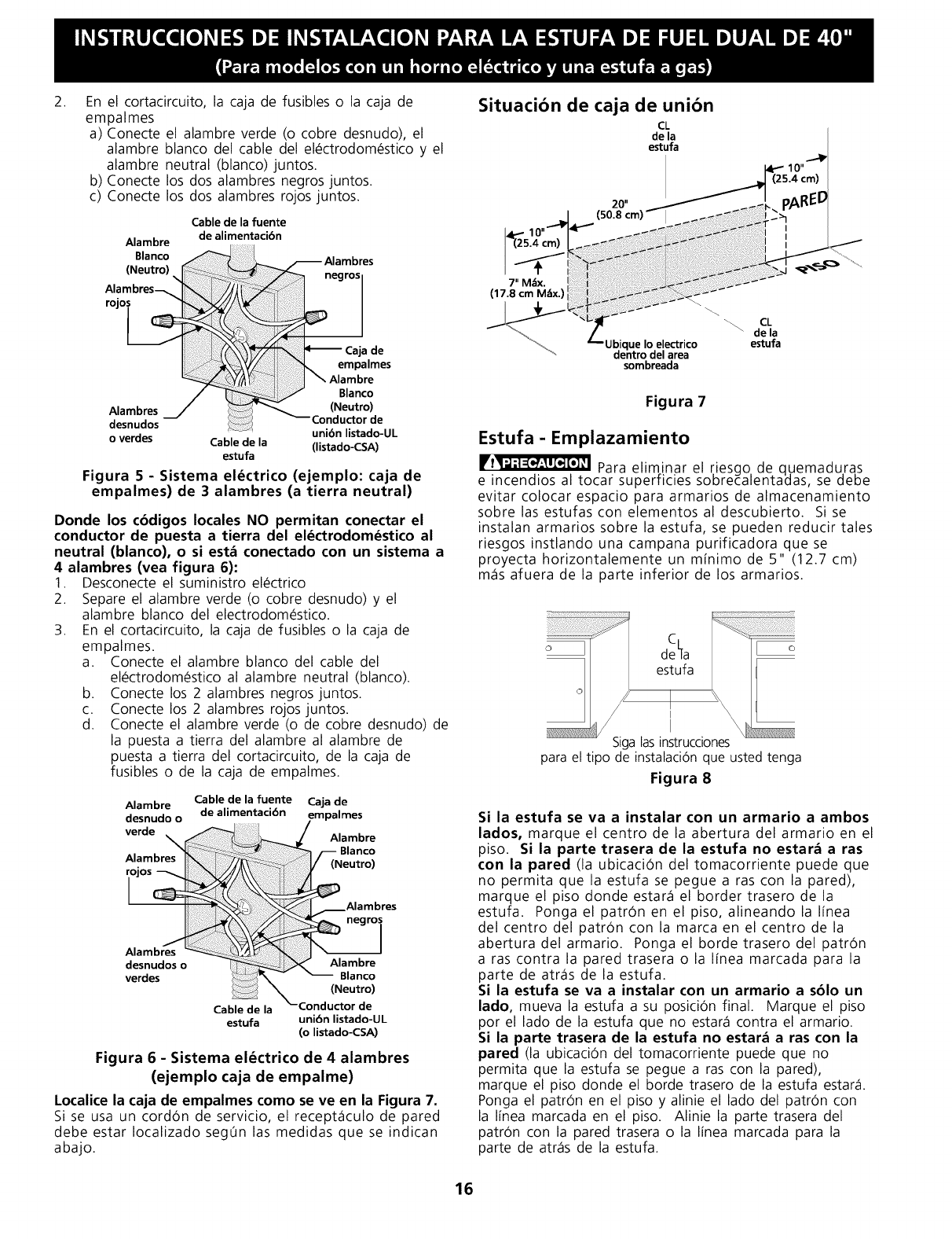
2. En el cortacircuito, la caja de fusibles o la caja de
empalmes
a) Conecte el alambre verde (o cobre desnudo), el
alambre blanco del cable del el_ctrodom_stico y el
alambre neutral (blanco)juntos.
b) Conecte los dos alambres negros juntos.
c) Conecte los dos alambres rojos juntos.
Cable de la fuente
de alimentacibn
Alambre
Blanco
(Neutro) _
Alambres_
r°l°_
AlambresJ
desnudos unibn listado-UL
o verdes Cable de la (listado-CSA)
estufa
Figura 5 - Sistema el_ctrico (ejemplo: caja de
empalmes) de 3alambres (a tierra neutral)
Donde los cbdigos locales NO permitan conectar el
conductor de puesta a tierra del el_ctrodom_stico al
neutral (blanco), o si est& conectado con un sistema a
4 alambres (vea figura 6):
1. Desconecte el suministro el_ctrico
2. Separe el alambre verde (o cobre desnudo) y el
alambre blanco del electrodom_stico.
3. En el cortacircuito, la caja de fusibles o la caja de
empalmes.
a. Conecte el alambre blanco del cable del
el_ctrodom_stico al alambre neutral (blanco).
b. Conecte los 2 alambres negros juntos.
c. Conecte los 2 alambres rojos juntos.
d. Conecte el alambre verde (o de cobre desnudo) de
la puesta a tierra del alambre al alambre de
puesta a tierra del cortacircuito, de la caja de
fusibles o de la caja de empalmes.
Alambre Cable de la fuente Caja de
estufa unibn listado-UL
(o listado-CSA)
Figura 6 - Sistema el_ctrico de 4 alambres
(ejemplo caja de empalme)
Localice la caja de empalmes como se ve en la Figura 7.
Si se usa un cord6n de servicio, el recept_culo de pared
debe estar Iocalizado seg0n las medidas que se indican
abajo.
Situacibn de caja de unibn
CL
de la
estufa
4_510"
.4 crn)
20" _ .... _ pAREI
m)_4. ...._ 50 8 cm i
_'s!O"c
I ;
7" M_x
(17.8 cm M_ix.)
"_ _ CL
/_de la
Z--Ubique Io electrico estufa
dentro del area
sombreada
Figura 7
Estufa - Emplazamiento
Para eliminar el riesgo de quemadu,ras
e incendios al tocar superficies soDrecalen[aaas, se GeDe
evitar colocar espacio para armarios de almacenamiento
sobre las estufas con elementos al descubierto. Si se
instalan armarios sobre la estufa, se pueden reducir tales
riesgos instlando una campana purificadora que se
proyecta horizontalemente un m[nimo de 5" (1 2.7 cm)
m_s afuera de la parte inferior de los armarios.
para el tipo de instalaci6nque ustedtenga
Figura 8
Si la estufa se va a instalar con un armario a ambos
lados, marque el centro de la abertura del armario en el
piso. Si la parte trasera de la estufa no estar_ a ras
con la pared (la ubicaci6n del tomacorriente puede que
no permita que la estufa se pegue a ras con la pared),
marque el piso donde estar_ el border trasero de la
estufa. Ponga el patr6n en el piso, alineandola I[nea
del centro del patron con la marca en el centro de la
abertura delarmario. Ponga el bordetraserodel patron
a ras contra la pared trasera o la I[nea marcada para la
parte de atr_s de la estufa.
Si la estufa se va a instalar con un armario a sblo un
lado, mueva la estufa a su posici_n final. Marque el piso
por el lado de la estufa que no estar_ contra el armario.
Si la parte trasera de la estufa no estar_ a ras con la
pared (la ubicaci_n del tomacorriente puede que no
permita que la estufa se pegue a ras con la pared),
marque el piso donde el borde trasero de la estufa estar_.
Ponga el patr6n en el piso y alinie el lado del patron con
la I[nea marcada en el piso. Alinie la parte trasera del
patron con la pared trasera o la I[nea marcada para la
parte de atr_s de la estufa.
16
Si la estufa no serd instalada junta contra un armario,
mueva la estufa a su posici6n final. Marque el piso por los
dos lados de la estufa. Si la parte trasera de la estufa
no estar_ a ras con la pared (la ubicaci6n del
tomacorriente puede que no permita que la estufa se
pegue a ras con la pared), marque en el piso donde el
borde trasero de la estufa estar_. Ponga el patron en el
piso y alinie los lados del patron con las I[neas marcadas
en el piso. Alinie la parte trasera del patron con la pared
trasera o la I[nea marcada para la parte trasera de la
estufa (vea Instalaci0n del Soporte Antivuelco p_gina 10).
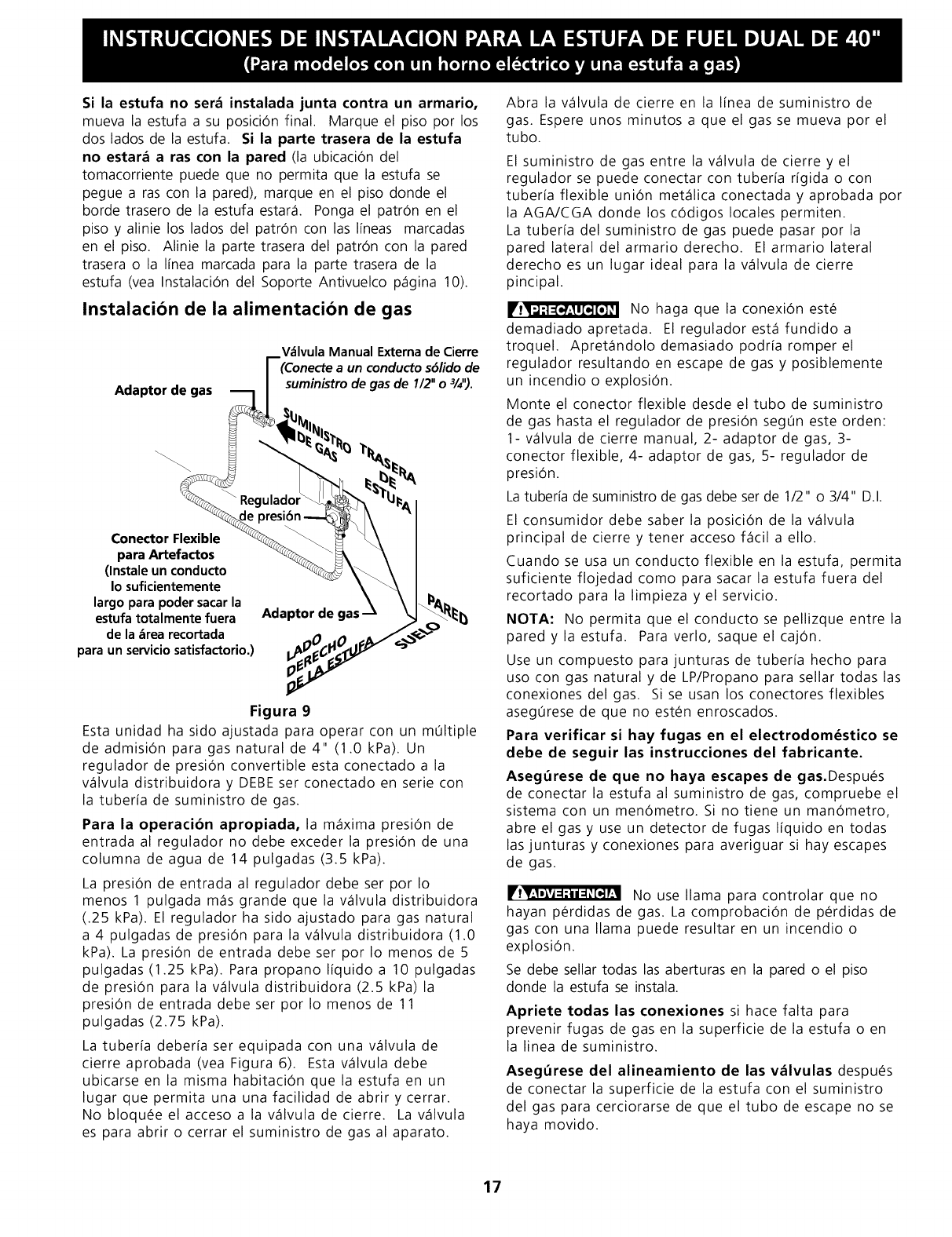
Instalaci6n de la alimentaci6n de gas
Adaptor de gas
V_lvula Manual Externa de Cierre
(Conecte a un conducto sdlido de
suminbtro de gas de I/2" o %").
Reguladol
,r
F
Conector Flexible
para Artefactos
(Instale un conducto
Io suficientemente
largo para poder sacarla
estufa totalmente fuera
de la _rea recortada
para un serviciosatisfactorio.)
Adaptor de gas
Figura 9
Esta unidad ha sido ajustada para operar con un m01tiple
de admisi0n para gas natural de 4" (1.0 kPa). Un
regulador de presiOn convertible esta conectado a la
v_lvula distribuidora y DEBE ser conectado en serie con
la tuber[a de suministro de gas.
Para la operaci6n apropiada, la m_xima presi0n de
entrada al regulador no debe exceder la presiOn de una
columna de agua de 14 pulgadas (3.5 kPa).
La presiOn de entrada al regulador debe ser por Io
menos 1 pulgada m_s grande que la v_lvula distribuidora
(.25 kPa). El regulador ha sido ajustado para gas natural
a 4 pulgadas de presiOn para la v_lvula distribuidora (1.0
kPa). La presi0n de entrada debe ser por Io menos de 5
pulgadas (1.25 kPa). Para propano I[quido a 10 pulgadas
de presiOn para la v_lvula distribuidora (2.5 kPa)la
presiOn de entrada debe ser por Io menos de 11
pulgadas (2.75 kPa).
La tuber[a deber[a ser equipada con una v_lvula de
cierreaprobada (vea Figura 6). Esta v_lvula debe
ubicarse en la misma habitaci0n que la estufa en un
lugar que permita una una facilidad de abrir y cerrar.
No bloqu_eelaccesoa la v_lvula decierre. La v_lvula
es para abrir o cerrar el suministro de gas al aparato.
Abra la v_lvula de cierre en la I[nea de suministro de
gas. Espere unos minutos a que el gas se mueva por el
tubo.
El suministro de gas entre la v_lvula de cierre y el
regulador se puede conectar con tuber[a r[gida o con
tuber[a flexible union met_lica conectada y aprobada por
la AGA/CGA donde los cOdigos locales permiten.
La tuber[a del suministro de gas puede pasar por la
pared lateral delarmarioderecho. Elarmariolateral
derecho es un lugar ideal para la v_lvula de cierre
pincipal.
No haga que la conexi0n est_
demadiadoapretada. El reguladorest_ fundidoa
troquel. Apret_ndolo demasiado podr[a romper el
regulador resultando en escape de gas y posiblemente
un incendio o explosion.
Monte el conector flexible desde el tubo de suministro
de gas hasta el regulador de presiOn seg0n este orden:
1- v_lvula de cierre manual, 2- adaptor de gas, 3-
conector flexible, 4- adaptor de gas, 5- regulador de
presiOn.
Latuber[a de suministro de gas debe ser de 1/2" o 3/4" D.I.
El consumidor debe saber la posiciOn de la v_lvula
principal de cierre y tener acceso f_cil a ello.
Cuando se usa un conducto flexible en la estufa, permita
suficiente flojedad como para sacar la estufa fuera del
recortado para la limpieza y el servicio.
NOTA: No permita queelconductose pellizqueentre la
pared yla estufa. Para verlo, saqueelcajOn.
Use un compuesto para junturas de tuber[a hecho para
uso con gas natural y de LP/Propano para sellar todas las
conexiones del gas. Si se usan los conectores flexibles
aseg0rese de que no est_n enroscados.
Para verificar si hay fugas en el electrodom_stico se
debe de seguir las instrucciones del fabricante.
Asegt_rese de que no haya escapes de gas.Despu_s
de conectar la estufa al suministro de gas, compruebe el
sistema con un menOmetro. Si no tiene un manOmetro,
abre el gas y use un detector de fugas I[quido en todas
las junturas y conexiones para averiguar si hay escapes
de gas.
No use llama para controlar que no
hayan p_rdidas de gas. La comprobaciOn de p_rdidas de
gas con una llama puede resultar en un incendio o
explosion.
Se debe sellar todas las aberturas en la pared o el piso
donde la estufa se instala.
Apriete todas las conexiones si hace falta para
prevenir fugas de gas en la superficie de la estufa o en
la linea de suministro.
Aseg_rese del alineamiento de las v_lvulas despu_s
de conectar la superficie de la estufa con el suministro
del gas para cerciorarse de que el tubo de escape no se
haya movido.
17
Desconecte esta estufa y su v&lvula individual de
cierre del sistema del siministro de gas durante
cualquier prueba de presi6n de ese sistema a presiones
mayores de 1/2 psig (3.5 kPa o 14" columna de agua).
Conversi6n para uso de Propano Liquido
Este aparato puede ser usado con gas natural o propano
I[quido. Ha sido ajustado en la f_brica para operar con
gas natural solamente.
Si desea convertir su estufa para uso con propano
I[quido, use los orificios provistos ubicados en el bolso
que contiene la literatura titulada "FOR LP/PROPANE
GAS CONVERSION." Siga las instrucciones que vienen
con los orificios.
La conversi6n debe ser efectuado por un t_cnico de
servicio capacitado, de acuerdo con las instrucciones del
fabricante y con todos los c6digos y requisitos de las
autoridades correspondentes. El no seguir las
instrucciones podr[a dar como resultado lesiones graves
odaflosa la propiedad. EIorganismoautorizado para
Ilevar a cabo este trabajo asume la responsabilidad de la
conversi6n.
rrT__E1 La falta de una conversi6n apropiada
puede resultar en lesiones graves y daflos a la
propiedad.
La instalaci6n y el servicio de
mantenimiento deben ser efectuados por un instalador
calificado, la agencia de servicio o el proveedor de gas.
La mudanza del aparato para reparaciones o
limpieza
Apague la corriente el_ctrica a la estufa a la fuente de
poder principal, y apague la v_lvula de cierre manual de
gas. Aseg0rese de que la estufa est_ fresca. Quite el caj6n
de servicio y abre la puerta del horno. Levante la frente de
la estufa y desl[cela fuera de la abertura sin crear tensi6n
desmedida sobre el conducto flexible de gas.
Aisla la estufa del sistema del suministro de gas
cerrando su v_lvula manual de cierre individual durante
cualquier prueba de presi6n del suministro del gas a
presiones iguales a menos de 1/2 psgi (.5 kPa o 14"
columna de agua).
Aseg0rese de no pellizque el conducto flexible de gas
detr_s de la estufa al reemplazar la unidad en la abertura.
Reemplace el caj6n, cierre la puerta y enciende el gas y la
corriente el_ctrica a la estufa.
El regulador debe desconectarse antes de mover el
aparato, si el regulador de la estufa se conecta a una
cafleria r[gida.
Reensamble en orden inverso (consulte Figura 9).
18
Instalacibn de la estufa
Mientras se desembala la estufa, ne
deseche los cuatro (4) pernos de embabalaje.
Reempl_flcelos como patas niveladoras y para ajustar la
altura de la unidad.
NOTA:
1. La parte trasera de la estufa puede ser directamente
instalada a ras con la pared trasera de la estructura.
2. Para reducir posibles marcas o rayas de las paredes
verticales y minimizar los riesgos de choques el_ctricos
en caso de condiciones de uso anormales como alto
calor o no cazuelas, y para conformar a los requisitos
de A.G.A, un espacio m[nimo de 2 Y2" (6.4 cm) debe
de ser provisto en ambos lados de la plancha de
cocinar.
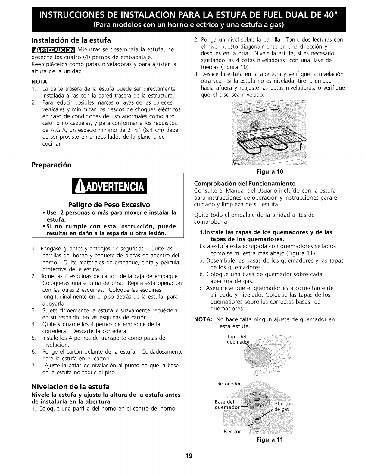
2. Ponga un nivel sobre la parrilla. Tome dos lecturas con
el nivel puesto diagonalmente en una direcci6n y
despu_s en la otra. Nivele la estufa, si es necesario,
ajustando las 4 patas niveladoras con una Ilave de
tuercas (Figura 10).
3. Deslice la estufa en la abertura y verifique la nivelaci6n
otra vez. Si la estufa no es nivelada, tire la unidad
hacia afuera y reajuste las patas niveladoras, o verifique
que el piso sea nivelado.
Preparacibn
Peligro de Peso Excesivo
• Use 2 personas o m&s para mover e instalar la
estufa.
•Si no cumple con esta instruccibn, puede
resultar en da_o a la espalda u otra lesibn.
1. P0ngase guantes y anteojos de seguridad. Quite las
parrillas del horno y paquete de piezas de adentro del
horno. Quite materiales de empaque, cinta y pel[cula
protectiva de la estufa.
2. Tome las 4 esquinas de cart6n de la caja de empaque.
Col0quelas una encima de otra. Repita esta operaci0n
con las otras 2 esquinas. Coloque las esquinas
Iongitudinalmente en el piso detr_fls de la estufa, para
apoyarla.
3. Sujete firmemente la estufa y suavamente recu_stela
en su respaldo, en las esquinas de carton.
4. Quite y guarde los 4 pernos de empaque de la
corredera. Descarte la corredera.
5. Instale los 4 pernos de transporte como patas de
nivelaciOn.
6. Ponge el carton delante de la estufa. Cuidadosamente
pare la estufa en el carton.
7. Ajuste la patas de nivelaciOn al punto en que la base
de la estufa no toque el piso.
Nivelacibn de la estufa
Nivele la estufa y ajuste la altura de la estufa antes
de instalarla en la abertura.
1. Coloque una parrilla del horno en el centro del horno.
Figura 10
Comprobaci6n del Funcionamiento
Consulte el Manual del Usuario inclu[do con la estufa
para instrucciones de operaciOn y instrucciones para el
cuidado y limpieza de su estufa.
Quite todo el embalaje de la unidad antes de
comprobarla.
1.1nstale las tapas de los quemadores y de las
tapas de los quemadores.
Esta estufa esta equipada con quemadores sellados
como se muestra m_flsabajo (Figura 11).
a. Desembale las basas de los quemadores y las tapas
de los quemadores.
b. Coloque una basa de quemador sobre cada
abertura de gas.
c. Asegurese que el quemador est_fl correctamente
alineado y nivelado. Coloque las tapas de los
quemadores sobre las correctas basas de
quemadores.
NOTA: No hacefalta ning0n ajuste de quemadoren
esta estufa.
Recogedor
Base del Abertura
quemador de gas
Electrodo
Figura 11
19
.
,
4.
Enciende la corriente eldctrica y abre la vdlvula
principal de cierre.
Comprobacion de los Encendedores
El funcionamiento de los encendedores el_ctricos
debe ser comprobado despu_s de que la estufa y los
conectores a la tuber[a de suministro de gas hayan
sido comprobados por escapes y la estufa haya sido
conectada el_ctricamente. Para comprobarqueel
encendido sea correcto:
a. Empuje y gire una perilla del quemador superior
hasta la posici6n LITE (encender). Se podr[a o[r
el encendedor haciendo chispas.
b. El quemador se deber_ encender en cuatro (4)
segundos para un funcionamiento normal, luego
de que el aire haya sido purgado de la tuber[a
de suministro de gas. Controlevisualmente que
el quemador se hay encendido.
c. Luego que el quemador se haya encendido, la
perilla debe ser girada fuera de la posici6n LITE.
Cada quemador tiene su encendedor individual.
Controle las perillas separadamente hasta que todas
las v_lvulas hayan sido controladas.
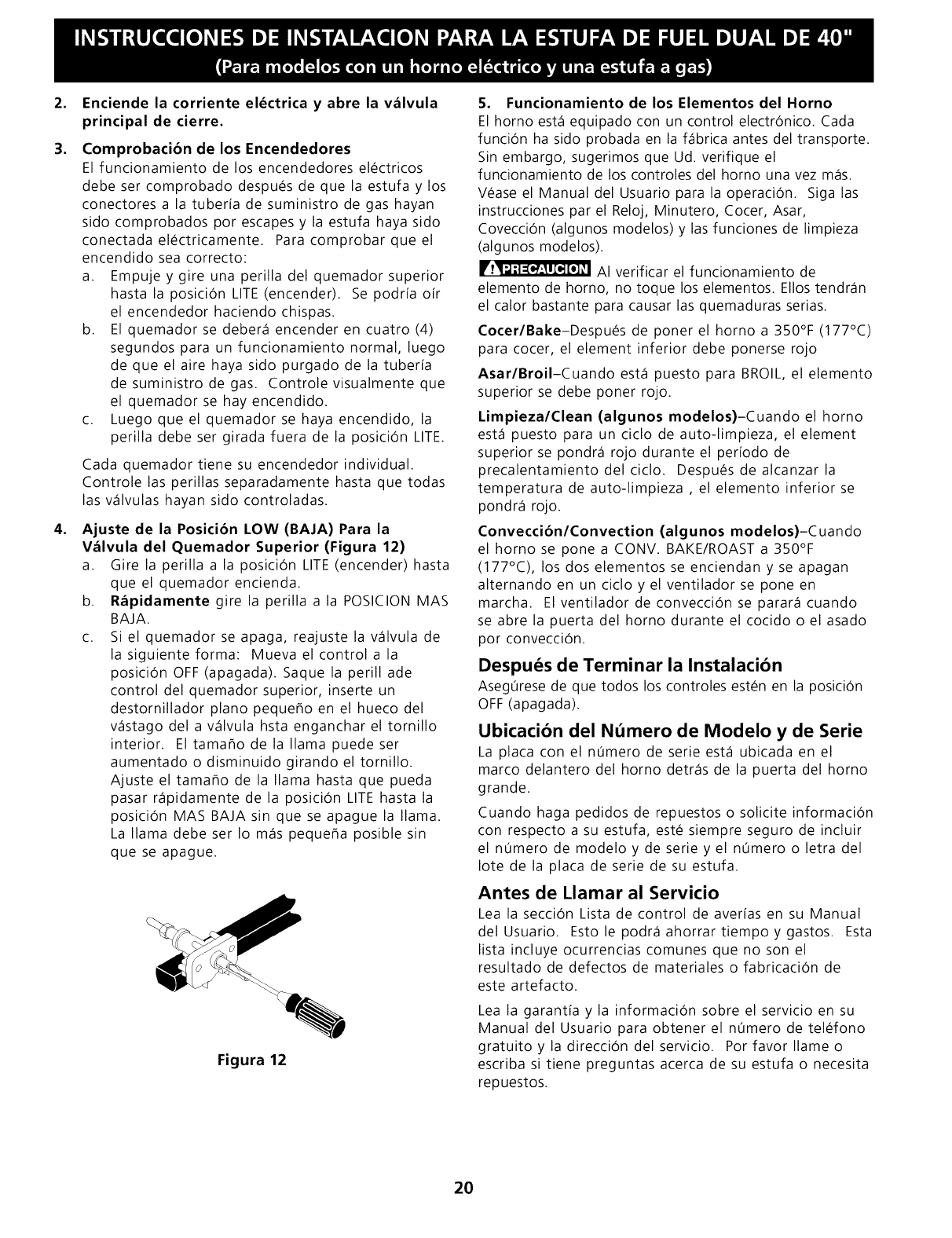
Ajuste de la Posicibn LOW (BAJA) Para la
Vdlvula del Quemador Superior (Figura 12)
a. Gire la perilla a la posici6n LITE (encender) hasta
que el quemador encienda.
b. R_pidamente gire la perilla a la POSICION MAS
BAJA.
c. Si el quemador se apaga, reajuste la v_lvula de
la siguienteforma: Mueva el controla la
posici6n OFF (apagada). Saque la perill ade
control del quemador superior, inserte un
destornillador piano pequefio en el hueco del
v_stago del a v_lvula hsta enganchar el tornillo
interior. EItamaflode la llama puedeser
aumentado o disminuido girando el tornillo.
Ajuste el tamaflo de la llama hasta que pueda
pasar r_pidamente de la posici6n LITE hasta la
posici6n MAS BAJA sin que se apague la llama.
La llama debe ser Io m_s pequefia posible sin
que se apague.
Figura 12
5. Funcionamiento de los Elementos del Horno
El horno est_ equipado con un control electr6nico. Cada
funci6n ha sido probada en la f_brica antes del transporte.
Sin embargo, sugerimos que Ud. verifique el
funcionamiento de los controles del horno una vez m_s.
V_ase el Manual del Usuario para la operaci6n. Siga las
instrucciones par el Reloj, Minutero, Cocer, Asar,
Covecci6n (algunos modelos) y las funciones de limpieza
(algunos modelos).
AI verificar el funcionamiento de
elemento de horno, no toque los elementos. EIIos tendr_n
el calor bastante para causar las quemaduras serias.
Cocer/Bake-Despu_s de poner el horno a 350°F (177°C)
para cocer, el element inferior debe ponerse rojo
Asar/BroiI-Cuando est_ puesto para BROIL, el elemento
superior se debe poner rojo.
Limpieza/Clean (algunos modelos)-Cuando el horno
est_ puesto para un ciclo de auto-limpieza, el element
superior se pondr_ rojo durante el per[odo de
precalentamientodelciclo. Despu_s dealcanzar la
temperatura de auto-limpieza , el elemento inferior se
pondr_ rojo.
Convecci6n/Convection (algunos modelos)-Cuando
el homo se pone a CONV. BAKE/ROAST a 350°F
(177°C), los dos elementos se enciendan y se apagan
alternando en un ciclo y el ventilador se pone en
marcha. EIventilador deconvecci6n se parar_ cuando
se abre la puerta del homo durante el cocido o el asado
por convecci6n.
Despu_s de Terminar la Instalaci6n
Aseg0rese de que todos los controles est_n en la posici6n
OFF (apagada).
Ubicaci6n del N_mero de Modelo y de Serie
La placa con el n0mero de serie est_ ubicada en el
marco delantero del homo detr_s de la puerta del homo
grande.
Cuando haga pedidos de repuestos o solicite informaci6n
con respecto a su estufa, est_ siempre seguro de incluir
el n0mero de modelo y de serie y el n0mero o letra del
Iote de la placa de serie de su estufa.
Antes de Llamar al Servicio
Lea la secci6n Lista de control de aver[as en su Manual
del Usuario. Estole podr_ahorrartiempoygastos. Esta
lista incluye ocurrencias comunes que no son el
resultado de defectos de materiales o fabricaci6n de
este a rtefacto.
Lea la garant[a y la informaci6n sobre el servicio en su
Manual del Usuario para obtener el n0mero de tel_fono
gratuito y la direcci6n del servicio. Por favor Ilame o
escriba si tiene preguntas acerca de su estufa o necesita
repuestos.
2O
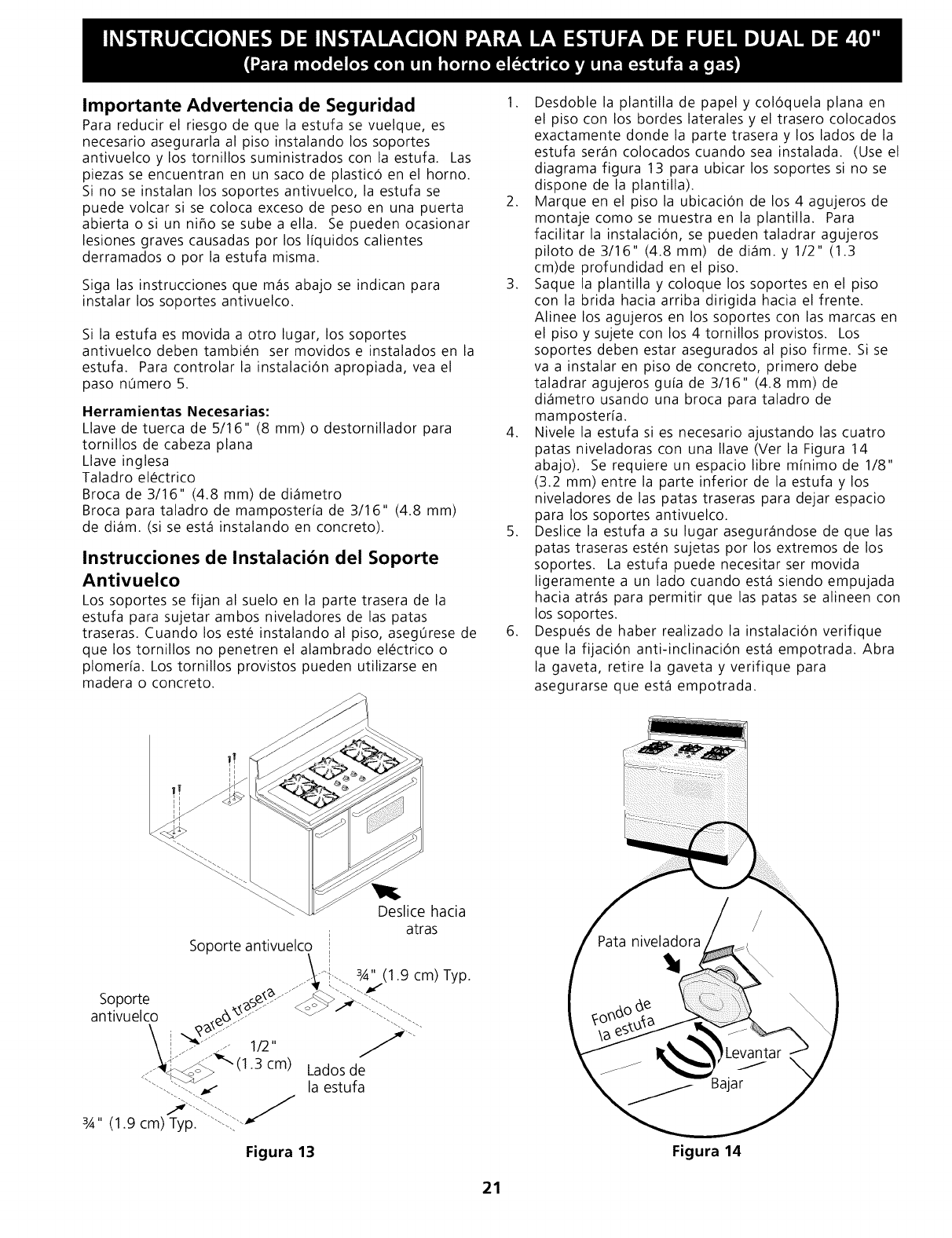
Importante Advertencia de Seguridad
Para reducir el riesgo de que la estufa se vuelque, es
necesario asegurarla al piso instalando los soportes
antivuelco y los tornillos suministrados con la estufa. Las
piezas se encuentran en un saco de plastic6 en el horno.
Si no se instalan los soportes antivuelco, la estufa se
puede volcar si se coloca exceso de peso en una puerta
abierta osi un niflosesubea ella. Se puedenocasionar
lesiones graves causadas por los I[quidos calientes
derramados o por la estufa misma.
Siga las instrucciones que m_s abajo se indican para
instalar los soportes antivuelco.
Si la estufa es movida a otro lugar, los soportes
antivuelcodebentambi_n sermovidose instaladosen la
estufa. Para controlar la instalaci6n apropiada, vea el
paso n0mero 5.
Herramientas Necesarias:
Llave de tuerca de 5/16" (8 mm) o destornillador para
tornillos de cabeza plana
Llave inglesa
Taladro el_ctrico
Broca de 3/16" (4.8 mm) de di_metro
Broca para taladro de mamposter[a de 3/1 6" (4.8 mm)
de di_m. (si se est_ instalando en concreto).
Instrucciones de Instalacibn del Soporte
Antivuelco
Los soportes se fijan al suelo en la parte trasera de la
estufa para sujetar ambos niveladores de las patas
traseras. Cuando los est_ instalando al piso, aseg0rese de
que los tornillos no penetren el alambrado el_ctrico o
plomer[a. Los tornillos provistos pueden utilizarse en
madera o concreto.
1. Desdoble la plantilla de papel y col6quela plana en
el piso con los bordes laterales y el trasero colocados
exactamente donde la parte trasera y los lados de la
estufa ser_n colocados cuando sea instalada. (Use el
diagrama figura 13 para ubicar los soportes si no se
dispone de la plantilla).
2. Marque en el piso la ubicaci6n de los 4 agujeros de
montajecomose muestraen la plantilla. Para
facilitar la instalaci6n, se pueden taladrar agujeros
piloto de 3/16" (4.8mm) dedi_m.y 1/2" (1.3
cm)de profundidad en el piso.
3. Saque la plantilla y coloque los soportes en el piso
con la brida hacia arriba dirigida hacia el frente.
Alinee los agujeros en los soportes con las marcas en
el piso y sujete con los 4 tornillos provistos. Los
soportes deben estar asegurados al piso firme. Si se
va a instalar en piso de concreto, primero debe
taladrar agujeros gu[a de 3/16" (4.8 mm) de
di_metro usando una broca para taladro de
mamposter[a.
4. Nivele la estufa si es necesario ajustando las cuatro
patas niveladoras con una Ilave (Ver la Figura 14
abajo). Se requiereunespaciolibre m[nimode 1/8"
(3.2 mm) entre la parte inferior de la estufa y los
niveladores de las patas traseras para dejar espacio
para los soportes antivuelco.
5. Deslice la estufa a su lugar asegur_ndose de que las
patas traseras est_n sujetas por los extremos de los
soportes. La estufa puede necesitar ser movida
ligeramente a un lado cuando est_ siendo empujada
hacia atr_s para permitir que las patas se alineen con
los soportes.
6. Despu_s de haber realizado la instalaci6n verifique
que la fijaci6n anti-inclinaci6n est_ empotrada. Abra
la gaveta, retire la gaveta y verifique para
asegurarse que est_ empotrada.
Soporte antivuelco
Deslice hacia
atras
i
_-,. 3,4" (1.9 cm) Typ.
lados de
la estufa
Figura 13 Figura 14
21

NOTAS:
22
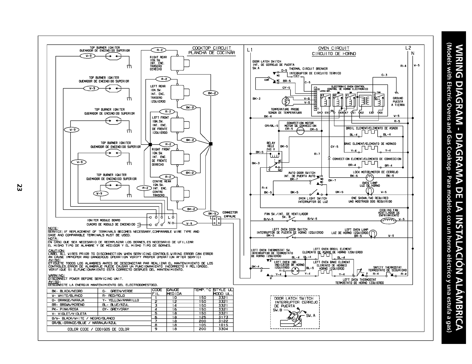
TOP BURNER IGNITER _COOKTOP CIRCU]T
OUEHA(]OR DE ENCEN(]IDO SUPERIOR _PLANCHA DE COCINAR
IGN. SW.
I_:%c. I I-1
TRASERO I I_J
T(]P BURNER IGNITER ___
(]UEMADOR DE ENCENDIO(] SUPERIOR
,ON.S%(].I D
TRRSER(]
T(]POORNER,GN,TER I_Bo
OUENA(]OR DE ENCENDIDO SUPERIOR
LEFT FRONT
INT. ENC.
T(]P BURNER IGNITER /
(]UEMADOR DE ENCENDI(](] SUPERIOR
RIGHT FRONT
IGN. SV.
INT. ENC.
Q _ DE FRENTE
(]ERECHO
TOP BURNER IGNITER
OUEMAD(ORDE ENCENOIOO SUPERIOR CENTRE REAR
____--- _ LI'_'_ C(]NNECTORIE
IGNITER NODULE BOARD _[--0 _ _
CUADRO DE N(]OULO DE ENCENDID(] N 0
NOTE:
SERVICE: IF REPLACEHENT OF TERHINALS BECOHES NECESSARY.COHPARABLE WINE TYPE AND
GAGE AND COMPARASI-E TERMINALS MUST BE USED.
NOTA:
EN CASO OUE SEA NECESARIO DE NEEMPLAZAR LOS BORNES. ES NECESARIO DE UTILIZAR
EL MISMO TIPO DE ALAHSNE Y OE HEDIOOR Y EL MISMO TIPO DE 80RNES.
LABEL PJ-L WIRES PRIOR TO DISCONNECTION gHEN _RVICING CONTROLS.WIRING ERROR CAN ERROR
CA_ IMPROPER AND DANGERO_ OPERATION VERIFY PROPER OPERATION AFTER SERVICI
AVISO:
ETIOUETE TODOS LOS ALAMBRES ANTES DE DE_ONECTP, Rp.e_:_ _ALIZ,e_R EL MP,NTENIMIENTO _ LOS
CONTROLES.ERROR DE ALAIHBRAJE PLIEDE CAUSAR UN FUNCIDNAMIENTO INCORRECTO Y PELIGR_O.
VERIFIQUE 81 ELFUNC:[ONAHIENTO ESTA CClI_:_ECTO DEBPUES DEL MANTENIMIENTO.
gARNING:
DISCONNECT PO_ER BEFORE _RVICING UNIT.
AV[SO:
DEEONECTE LA ENERGIA HANTENIMIENTO OEL ELECTROOOHESTOCO.
OK- BLACK/NEGRO G- GREEN/VERDE COD_GAUGE TEMP. "__
W- WHITE/BLANCO R-ED/ROJO FII_HED[DA _ODO UL.m_.
I I0 150 3321
O- ORANGE/NARAJA Y- YELLOW/AMARILLO _ 12 15_ 332_
BR- BROWN/MORENO BL- BLUE/AZUL 314 150 3321
PK- PINK/ROSA GY- GREY/GRAY 4 16 150 3321
V- V I OLET/V I OLETA 5 18 150 3321
B/W- BLACK/WH [TE /NEGRO/BLAk(;O 618 125 3173
OR/BL-ORANGE/BLUE /NARANJA/AZLL "7 18 200 312_
_B io_ _o_
COLOR CODE /COOIGOS BE COLOR 9 18 200 3304
OVEN CIRCUIT
CIRCUITO DE HORNO
DOOR LATCH SWITCH
INT. DE CERROJO DE PUERTA R-4
SW.A 0-5 THERMAL CIRCUIT BREAKER
INTERRUPTOR DE CIRCUIT(] TERBIC(] G 3
_"-_--U___
_lO CONTROLDE HORNOELECTRONICO
I.d_5SONDADE TENPERATURA E41, E5 : E7 I)E8
B!<_SONOADETENPERATURAI TOT'T"TO'"'
CONVECTIONMOTOR I I _.__ R-S
o_..e.-_ __o_(]_VECC___. , IOR(]ILELENENT/ELENENTO DE ASA(]O I
RELAVILEELEMENT/ELEMENTBBEHORNE(]l
RELE K-5 ;Y-5 I r_ r_ r_ /
BK-3
AUTO DOOR SNITCH LOCK MOTOR/MOTOR OE CERROJO
INT. DE PUERTA AUTO _BK-6 _BK-B
BK-7 _OK-7
LUZ D HORNO
R-4
OK-5 BK-5 OK-5 t/-5
OVEN LIGHT SWITCH ONE SHOUN, T_/O REQUIRED
INTERRUPTOR BE LUZ UN(] MOSTRAD(] DOS RE(]UIRIOR
FAN 5_./INT. DE VENTILAOOR
B/_-5 SY._ 8_-5
LEFT OVEN ODOR SUITCH
INTERRUPTOR DE PUERTA DE HORNS IZOUIERD(]
OK-5
COOLING FAN
VENTILA(]OR (]E
ENFRIAMIENT(]
LEFT OVEN LAMP
LUZ DE HORNS IZGUIERDO(f _
BR-5 _ _-5
.EFT OVEN THERMOSTAT SW. LEFT OVEN BROIL ELEMENT
INTERRUPTOR DE TERNOSTATO ELEMENT(] DE ASA(]O DE HORN(] IZ(]UIER(](]
FLJ-L-_ _ .
DE HORNO IZOUIERDO BL-
""LEFT OVEN IND. I LEFT OVEN BARE ELEHENT
I_&_ "L"oI(]EHORNO_ B ELE.E.TOOEH(]RNEO
.__. ;_RNO. _HORNO,_BU,ERBO B.E.THERNB.TAT
TERMOBTATO (]E SE(]URIDADP Y-5
LEFT OVEN THERMOSTAT
TERMOSTATO DE HORNO IZOUIEROO
L2
N
4-5
DOOR LATCH S_]TCH
I NTERRUPTOR CERROJO
1--- S_. A

24
