Kenmore 79680441900 User Manual DRYER Manuals And Guides L0910077
KENMORE Residential Dryer Manual L0910077 KENMORE Residential Dryer Owner's Manual, KENMORE Residential Dryer installation guides
User Manual: Kenmore 79680441900 79680441900 KENMORE DRYER - Manuals and Guides View the owners manual for your KENMORE DRYER #79680441900. Home:Laundry & Garment Care Parts:Kenmore Parts:Kenmore DRYER Manual
Open the PDF directly: View PDF ![]() .
.
Page Count: 72
I I
®
Steam Dryers
Use & Oare Guiiide and _nsta_lllatiiW@n_nstructiiions
Secador con vapor
Gu_a de uso y cuidado e Jnstrucciones de insta_aci6n
Models/Modelos
Electric / Electrico 796.8002#9## /796.8027#9##
Gas / Gas 796.9002#9## /796.9027#9##
# = coEor number, n_mero de coEor
Protocol P154
Sanitization Performance of
Residential Clothes dryer
Protocolo P154
Ejecucion de Saneamiento en la
zona residencialSecadoras
3828EL3004V
Sears Brands Management Corporation, Hoffman Estates, IL 60179
Sears Canada Inc., Toronto, Ontario, Canada M5B 2B8
www.sears,com
www.sears.ca
I I
I I
IMPORTANT SAFETY INSTRUCTIONS
SAFETY MESSAGES ..................... 3
IMPORTANT SAFETY INSTRUCTIONS ................ 3-6
FEATURES AND BENEFITS
Key Parts and Components ..................... 7
INSTALLATION INSTRUCTIONS
Key Dimension and Specifications ..................... 8
Location Requirements ........................ 8
Choose the Proper Location .................... 8
Clearances ................................. 8
Installation with Optional Pedestal Base or Stacking Kit ..... 9
Optional Accessories ...................... 9
Gas Requirements ........................... 10
Connecting Gas Dryers ..................... 10,11
Electrical Requirements ....................... 12
Connecting Electric Dryers ................. 12,13
Venting the Dryer ..................... 14,15
Leveling the Dryer ..................... 16
Reversing the Door Swing ..................... 16
Final Installation Check ..................... 17
HOW TO USE
Control Panel Features ..................... 18
Operating the Dryer ..................... 19
Cycle Guide ................................ 20
Sorting Loads ................................ 21
Loading the Dryer ............................. 21
Time and Status Display ...................... 22
Cycle Modifier Buttons ....................... 23
Cycle Options and Special Features ........... 24
Wrinkle Guard .............................. 24
Control Lock .............................. 24
Sanitize Cycle ..................... 24
Rack Dry Cycle ..................... 24
Steam Functions ..................... 25
About Steam .............................. 25
Using the STEAM REFRESH Cycle ................. 25
Using the STATIC SHIELD Option .................. 25
To Fill the Steam Feeder ........................ 26
Important Notes about Steam Cycles ................ 26
USER MAINTENANCE INSTRUCTIONS
Regular Cleaning ...................... 27
Cleaning the Exterior ....................... 27
Cleaning the Interior ....................... 27
Cleaning Around and Under the Dryer ................ 27
Maintaining Ductwork ....................... 27
Cleaning the Lint filter ....................... 27
TROUBLESHOOTING GUIDE
Before Calling for Service ...................... 28-31
OPTIONAL ACCESSORIES
Stacking Kit Installation....................... 32
Pedestal Installation....................... 33
Side Venting Kit Installation .................... 34
WARRANTY ............................... 35
In the space below, record the date of purchase, model,
and serial number of your product. You will find the
model and serial number printed on an identification
plate located inside the dryer door. Have thesejtems
of information available whenever you contact Sears
concerning your product.
Model No.
Date of Purchase
Serial No.
Save these instructions and your sales receipt for
future reference. 2
Master Protection Agreements
Congratulations on making a smart purchase. Your new
Kenmore <"_'product is designed and manufactured for
years of dependable operation. But like all products, it
may require preventive maintenance or repair from time
to time. That's when having a Master Protection Agreement
can save you money and aggravation.
The Master Protection Agreement also helps extend the
life of your new product. Here's what the Agreement*
includes:
, Parts and labor needed to help keep products
operating properly under normal use, not just
defects. Our coverage goes weIH beyond the
product warranty. No deductible, no functional
failure excluded from coverage--real protection.
, Expert service by a force of more than 10,000
authorized Sears service technicians, which means
someone you can trust will be working on your
product.
, Unlimited service calls and nationwide service, as
often as you want us, whenever you want us.
, No-lemon guarantee--replacement of your covered
product if four or more product failures occur within
twelve months.
, Product replacement if your covered product can't
be fixed.
,Annual Preventive Maintenance Check at your
request--no extra charge.
,Fast help by phone--we call it Rapid Resolution.
Phone support from a Sears representative on all
products. Think of us as a talking owner's manual.
, Power surge protection against electrical damage
due to power fluctuations.
, $250 food loss protection annually for any food
spoilage that is the result of mechanical failure of any
covered refrigerator or freezer.
, Rental reimbursement if repair of your covered
product takes longer than promised.
,10% discount off the regular price of any
non-covered repair service and related installed
parts.
Once you purchase the Agreement, a simple phone call
is all that it takes for you to schedule service. You can
call anytime day or night or schedule a service
appointment online.
The Master Protection Agreement is a risk free
purchase.If you cancel for any reason during the
product warranty period, we will provide a full refund. Or
a prorated refund anytime after the product warranty
period expires. Purchase your Master Protection
Agreement today!
Some limitations and exclusions apply.
For prices and additional information in the U.S.A.
call 1=800=827-6655.
*Coverage in Canada varies on some items.
For full details call Sears Canada at 1-800-361-6665.
Sears InstaIHation Service
For Sears professional installation of home appliances,
garage door openers, water heaters, and other major
home items, in the U.S.A. or Canada, call
1-800-4-MY-HOM E_"_'.
I I
I I
Ri=AD ALL iNSTRUCTiONS BSFORS USE
minimize the risk of fire or explosion, electric shock, or to prevent property damage, personal injury,
or loss of life.
fYour Safety and the safety of others is very important.
We have provided many important safety messages in this manual and on your appliance. Always read and obey all
safety messages.
,_ This is the safety alert symbol.
This symbol alerts you to potential hazards that can kill or hurt you and others.
All safety messages will follow the safety alert symbol and either the word DANGER or WARNING.
These words mean:
DANGER: Youcanbe killed or seriously injured if you don't immediately follow instructions.
,& WARNING: You can be killed or seriously injured if you don't follow instructions.
All safety messages will tell you what the potential hazard is, tell you how to reduce the chance of injury, and tell you
what can happen if the instructions are not followed. J
Do not install aclothes dryer with flexible plastic venting materials. If flexible metal (foil type) duct
is installed, it must be of aspecific type identified by the appliance manufacturer as suitable for
use with clothes dryers. Flexible venting materials are known to collapse, be easily crushed, and
trap lint. These conditions will obstruct clothes dryer airflow and increase the risk of fire.
Do not store or use gasoline or other flammable vapors and liquids in the vicinity of this appliance
or any other appliances.
Installation and service must be performed by a qualified installer, service agency, or the gas
supplier.
Install the clothes dryer according to the manufacturer's instructions and local codes.
* Save these instructions.
WHAT TO DO iF YOU SMELL GAS:
1. Do not try to light amatch or cigarette, or turn on any gas or electrical appliance.
2. Do not touch any electrical switches. Do not use any phone in your building.
3. Clear the room, building, or area of all occupants.
4. Immediately call your gas supplier from a neighbor's phone. Follow the gas supplier's instructions
carefully.
5. if you cannot reach your gas supplier, call the fire department.
I I
I I
BASIC SAFETY PRECAUTIONS
aL WARNING:
follow basic precautions, including the following:
•Read all instructions before using the dryer.
• Before use, the dryer must be properly installed as
described in this manual.
• Do not place items exposed to cooking oils in your
dryer. Items contaminated with cooking oils may
contribute to a chemical reaction that could cause a
load to catch fire.
• Do not dry articles that have been previously cleaned
in, washed in, soaked in, or spotted with gasoline,
dry-cleaning solvents, or other flammable or explosive
substances as they give off vapors that could ignite or
explode.
• Do not reach into the dryer if the drum or any other
part is moving.
• Do not repair or replace any part of the dryer or
attempt any servicing unless specifically
recommended in this Use and Care Guide or in
published user-repair instructions that you understand
and have the skills to carry out.
• Do not tamper with controls.
• Before the dryer is removed from service or
discarded, remove the door to the drying
compartment.
To reduce the risk of fire, electric shock, or injury to persons when using this appliance,
• Do not allow children to play on or in the dryer. Close
supervision of children is necessary when the dryer is
used near children.
• Do not use fabric softeners or products to eliminate
static unless recommended by the manufacturer of
the fabric softener or product.
• Do not use heat to dry articles containing foam rubber
or similarly textured rubber-like materials.
• Keep area around the exhaust opening and adjacent
surrounding areas free from the accumulation of lint,
dust, and dirt.
• The interior of the dryer and exhaust vent should be
cleaned periodically by qualified service personnel.
• Do not install or store the dryer where it will be
exposed to the weather.
• Always check the inside of the dryer for foreign
objects.
• Clean lint filter before or after each load.
CALIFORNIA SAFE DRINKING WATER AND TOXIC ENFORCEMENT ACT
This act requires the governor of California to publish a list of substances known to the state to cause cancer, birth defects,
or other reproductive harm and requires businesses to warn customers of potential exposure to such substances.
Gas appliances can cause minor exposure to four of these substances, namely benzene, carbon monoxide, formaldehyde,
and soot, caused primarily by the incomplete combustion of natural gas or LP fuels.
Properly adjusted dryers will minimize incomplete combustion. Exposure to these substances can be minimized further by
properly venting the dryer to the outdoors.
GROUNDING INSTRUCTIONS
This appliance must be grounded. In the event of malfunction or breakdown, grounding will reduce the risk of electric shock
by providing a path of least resistance for electric current. This appliance must be equipped with a cord having an
equipment-grounding conductor and a grounding plug. The plug must be plugged into an appropriate outlet that is properly
installed and grounded in accordance with all local codes and ordinances.
ak WARNING: Improper connection of the equipment-grounding conductor can result in a risk of electric
shock. Check with a qualified electrician or service person if you are in doubt as to whether the appliance is properly
grounded. Do not modify the plug provided with the appliance. If it will not fit the outlet, have a proper outlet installed by a
qualified electrician. This appliance must be connected to a grounded metal, permanent wiring system or an equipment
grounding conductor must be run with the circuit conductors and connected to the equipment grounding terminal or lead
on the appliance. Electrical shock can result if the dryer is not properly grounded.
4
I I
I I
SAFETY INSTRUCTIONS FOR INSTALLATION
^AULWARNING: To reduce the risk of fire, electric shock, or injury to persons when using this appliance,
follow basic precautions, including the following:
Properly ground dryer to conform with all
governing codes and ordinances. Follow details in
the installation instructions. Electrical shock can result
if the dryer is not properly grounded.
Before use, the dryer must be properly installed
as described in this manual. Electrical shock can
result if the dryer is not properly grounded.
Install and store the dryer where it will not be
exposed to temperatures below freezing or
exposed to the weather.
All repairs and servicing must be performed by an
authorized servicer unless specifically
recommended in this Owner's Guide. Use only
authorized factory parts. Failure to follow this
warning can cause serious injury,fire, electrical
shock, or death.
To reduce the risk of electric shock, do not install
the dryer in humid spaces. Failure to follow this
warning can cause serious injury,fire, electrical
shock, or death.
Connect to a properly rated, protected, and sized
power circuit to avoid electrical overload. Improper
power circuit can melt, creating electrical shock
and/or fire hazard.
Remove all packing items and dispose of all
shipping materials properly. Failure to do so can
result in death, explosion, fire, or burns.
Place dryer at least 18 in. above the floor for a
garage installation. Failure to do so can result in
death, explosion, fire, or burns.
Keep all packaging from children. Packaging
material can be dangerous for children. There is a risk
of suffocation.
Do not install nearby heat item. Such as stove,
cooking oven. Failure to do so can cause deform,
smoke and fire.
Do not place candle and cigarettes on top of the
product. Failure to do so can cause deform, smoke
and fire.
Remove all protective vinyl film from the product.
Failure to do so can cause deform, smoke and fire.
Exhaust/Ducting"
Gas dryers MUST be exhausted to the outside.
Failure to follow these instructions can result in fire or
death.
The dryer exhaust system must be exhausted to
the outside of the dwelling. If the dryer is not
exhausted outdoors, some fine lint and large
amounts of moisture will be expelled into the
laundry area. An accumulation of lint in any area of
the home can create a health and fire hazard.
Use only rigid metal or flexible metal 4 in.
diameter ductwork inside the dryer cabinet or for
exhausting to the outside. Use of plastic or other
combustible ductwork can cause a fire. Punctured
ductwork can cause a fire if it collapses or becomes
otherwise restricted in use or during installation.
Ductwork is not provided with the dryer, and you
should obtain the necessary ductwork locally. The
end cap should have hinged dampers to prevent
backdraft when the dryer is not in use. Failure to
follow these instructions can result in fire or death.
The exhaust duct must be 4 in. (10.2 cm) in
diameter with no obstructions. The exhaust duct
should be kept as short as possible. Make sure to
clean any old ducts before installing your new
dryer. Failure to follow these instructions can result in
fire or death.
Rigid or semi rigid metal ducting is recommended
for use between the dryer and the wall. In special
installations when it is impossible to make a
connection with the above recommendations, a
ULlisted flexible metal transition duct may be
used between the dryer and wall connection only.
The use of this ducting will affect drying time.
Failure to follow these instructions can result in fire or
death.
DO NOT use sheet metal screws or other
fasteners which extend into the duct that could
catch lint and reduce the efficiency of the exhaust
system. Secure all joints with duct tape. For complete
details, follow the Installation Instructions. Failure to
follow these instructions can result in fire or death.
I I
I I
SAFETY INSTRUCTIONS FOR STEAM FUNCTIONS
WARNING: To reduce the risk of fire, electric shock, or injury to persons when using this appliance,
follow basic precautions, including the following:
• Do not open the dryer door during steam cycles.
Failure to follow these instructions can result in a burn
hazard.
•Do not dry articles that have been previously
cleaned in, washed in, soaked in, or spotted with
gasoline, dry-cleaning solvents, or other
flammable or explosive substances as they give
off vapors that could ignite or explode. Failure to
follow these instructions can result in fire or death.
Do not fill the steam feeder with gasoline,
dry-cleaning solvents, or other flammable or
explosive substances. Failure to follow these
instructions can result in fire or death.
Do not touch the steam nozzle in the drum during
or after the steam cycle. Failure to follow these
instructions can result in a burn hazard.
Do not fill the steam feeder with hot water (over
86°F/30°C). Failure to follow these instructions can
result in a burn hazard.
SAFETY INSTRUCTIONS FOR CONNECTING ELECTRICITY
WARNING: To reduce the risk of fire, electric shock, or injury to persons when using this appliance,
follow basic precautions, including the following:
•Do not, under any circumstances, cut or remove
the ground prong from the power cord. To prevent
personal injury or damage to the dryer, the electrical
power cord must be plugged into a properly grounded
outlet.
•For personal safety, this dryer must be properly
grounded. Failure to do so can result in electrical
shock or injury.
•Refer to the installation instructions in this
manual for specific electrical requirements for
your model. Failure to follow these instructions can
create an electrical shock hazard and/or a fire hazard.
•This dryer must be plugged into a properly
grounded outlet. Electrical shock can result if the
dryer is not properly grounded. Have the wall
outlet and circuit checked by a qualified
electrician to make sure the outlet is properly
grounded. Failure to follow these instructions can
create an electrical shock hazard and/or a fire hazard.
•The dryer should always be plugged into it's own
individual electrical outlet which has a voltage
rating that matches the rating plate. This provides
the best performance and also prevents overloading
house wiring circuits which could cause a fire hazard
from overheated wires.
Never unplug your dryer by pulling on the power
cord. Always grip plug firmly and pull straight out
from the outlet. The power cord can be damaged,
resulting in a risk of fire and electrical shock.
Repair or replace immediately all power cords that
have become frayed or otherwise damaged. Do
not use a cord that shows cracks or abrasion
damage along its length or at either end. The
power cord can melt, creating electrical shock and/or
fire hazard.
When installing or moving the dryer, be careful
not to pinch, crush, or damage the power cord.
This will prevent injury and prevent damage to the
dryer from fire and electrical shock.
SAVE THESE INSTRUCTIONS
6
I I
I I
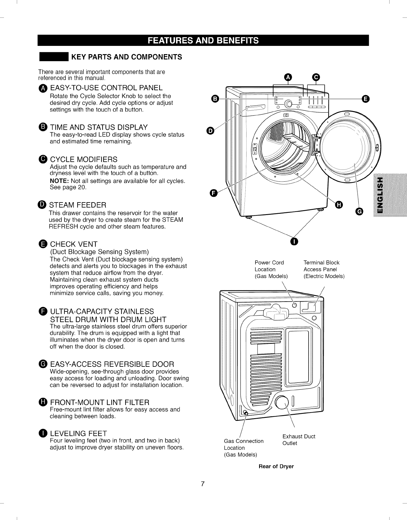
KEY PARTS AND COMPONENTS
There are several important components that are
referenced in this manual.
OEASY-TO-USE CONTROL PANEL
Rotate the Cycle Selector Knob to select the
desired dry cycle. Add cycle options or adjust
settings with the touch of a button.
O TIME AND STATUS DISPLAY
The easy-to-read LED display shows cycle status
and estimated time remaining.
CYCLE MODIFIERS
Adjust the cycle defaults such as temperature and
dryness level with the touch of a button.
NOTE: Not all settings are available for all cycles.
See page 20.
STEAM FEEDER
This drawer contains the reservoir for the water
used by the dryer to create steam for the STEAM
REFRESH cycle and other steam features.
O CHECK VENT
(Duct Blockage Sensing System)
The Check Vent (Duct blockage sensing system)
detects and alerts you to blockages in the exhaust
system that reduce airflow from the dryer.
Maintaining clean exhaust system ducts
improves operating efficiency and helps
minimize service calls, saving you money.
ULTRA-CAPACITY STAINLESS
STEEL DRUM WITH DRUM LIGHT
The ultra-large stainless steel drum offers superior
durability. The drum is equipped with a light that
illuminates when the dryer door is open and turns
off when the door is closed.
®EASY-ACCESS REVERSIBLE DOOR
Wide-opening, see-through glass door provides
easy access for loading and unloading. Door swing
can be reversed to adjust for installation location.
FRONT-MOUNT LINT FILTER
Free-mount lint filter allows for easy access and
cleaning between loads.
el LEVELING FEET
Four leveling feet (two in front, and two in back)
adjust to improve dryer stability on uneven floors.
Power Cord
Location
(Gas Models)
Terminal Block
Access Panel
(Electric Models)
Gas Connection
Location
(Gas Models)
Exhaust Duct
Outlet
Rear of Dryer
I I
I I
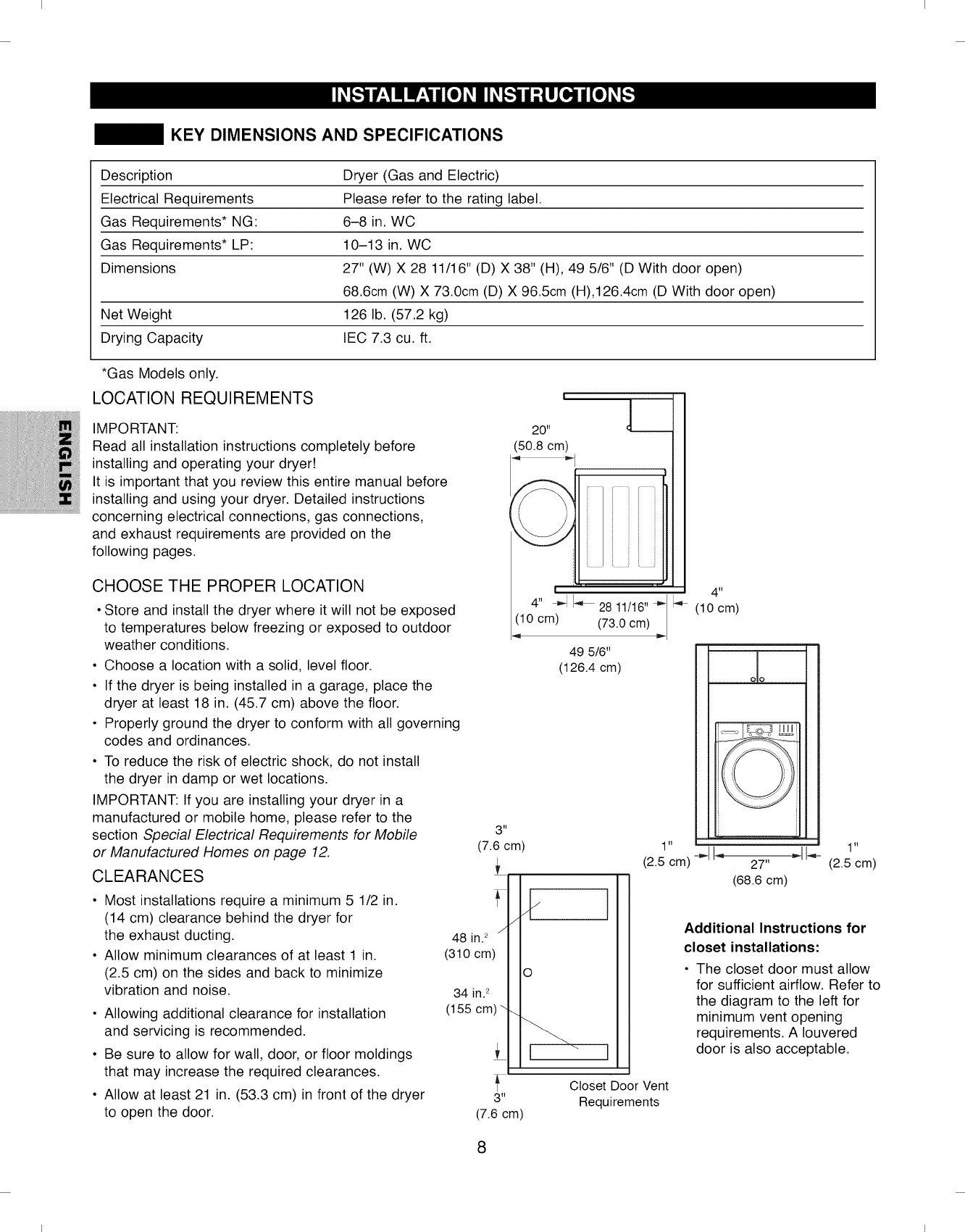
KEY DIMENSIONS AND SPECIFICATIONS
Description Dryer (Gas and Electric)
Electrical Requirements Please refer to the rating label.
Gas Requirements* NG: 6-8 in. WC
Gas Requirements* LP: 10-13 in. WC
Dimensions 27" (W) X 28 11/16" (D) X 38" (H), 49 5/6" (D With door open)
68.6cm (W) X 73.0cm (D) X 96.5cm (H),126.4cm (D With door open)
Net Weight 126 lb. (57.2 kg)
Drying Capacity IEC 7.3 cu. ft.
*Gas Models only.
LOCATION REQUIREMENTS
IMPORTANT:
Read all installation instructions completely before
installing and operating your dryer!
It is important that you review this entire manual before
installing and using your dryer. Detailed instructions
concerning electrical connections, gas connections,
and exhaust requirements are provided on the
following pages.
CHOOSE THE PROPER LOCATION
• Store and install the dryer where it will not be exposed
to temperatures below freezing or exposed to outdoor
weather conditions.
• Choose a location with a solid, level floor.
• If the dryer is being installed in a garage, place the
dryer at least 18 in. (45.7 cm) above the floor.
• Properly ground the dryer to conform with all governing
codes and ordinances.
• To reduce the risk of electric shock, do not install
the dryer in damp or wet locations.
IMPORTANT: If you are installing your dryer in a
manufactured or mobile home, please refer to the
section Special Electrical Requirements for Mobile
or Manufactured Homes on page 12.
CLEARANCES
• Most installations require a minimum 5 1/2 in.
(14 cm) clearance behind the dryer for
the exhaust ducting.
• Allow minimum clearances of at least 1 in.
(2.5 cm) on the sides and back to minimize
vibration and noise.
• Allowing additional clearance for installation
and servicing is recommended.
• Be sure to allow for wall, door, or floor moldings
that may increase the required clearances.
• Allow at least 21 in. (53.3 cm) in front of the dryer
to open the door.
3 ,I
(7.6 cm)
i
J
48 in.2
(310 cm)
34 in. 2
(155 cm) \
!
20"
(50.8 cm)
! ' ' ' ' ' 4"
4" -,.-II_,_2811/16"-- I_
(10 cm) (73.0 cm) =,- (10 cm)
49 5/6"
(126.4 cm) oo
I
io
1" -_1I_, _1_ 1"
(2.5 cm) 27" (2.5 cm)
(68.6 cm)
Additional Instructions for
closet installations:
• The closet door must allow
for sufficient airflow. Refer to
the diagram to the left for
minimum vent opening
requirements. A Iouvered
door is also acceptable.
Closet Door Vent
3" Requirements
(7.6 cm)
8
I I
I I
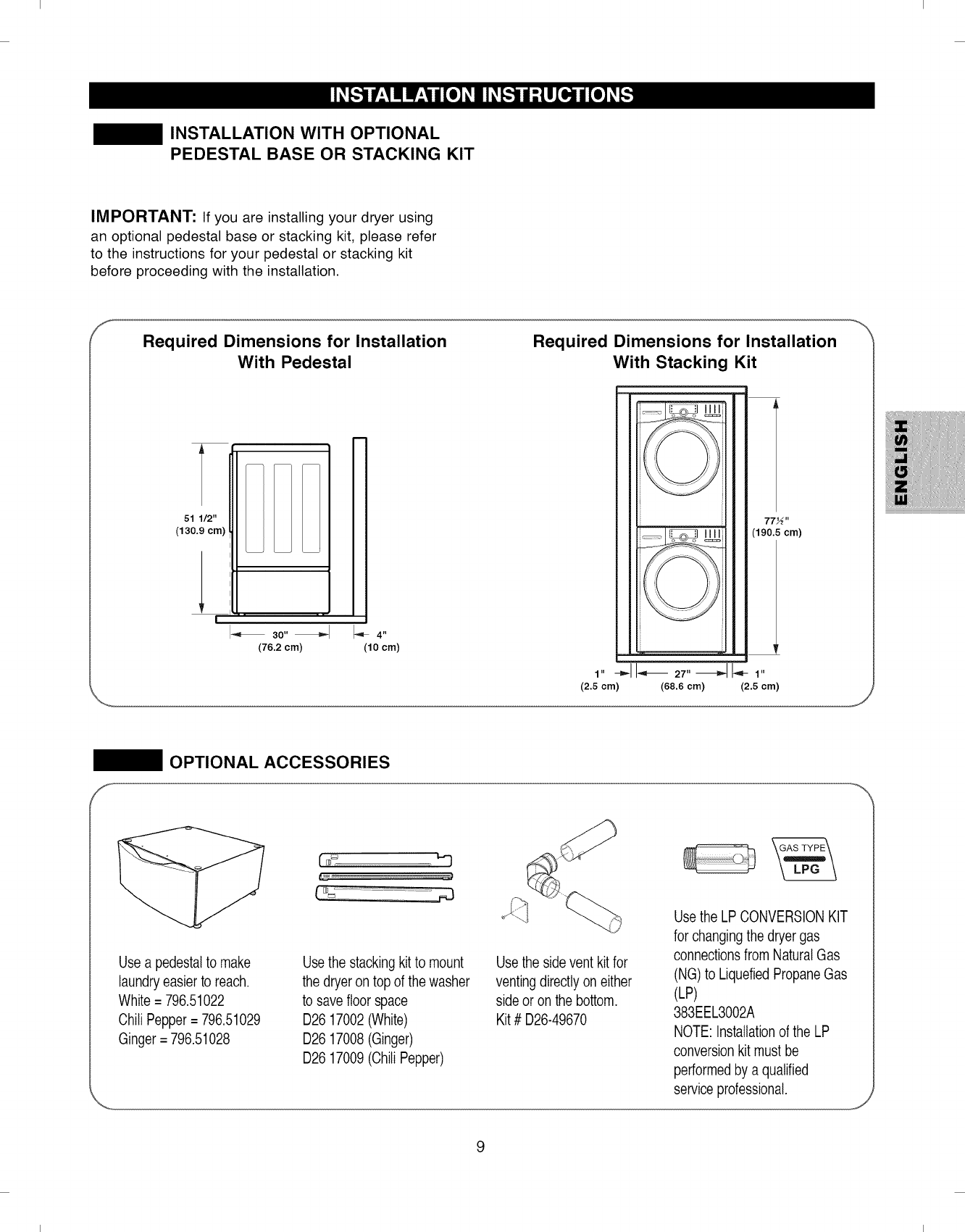
INSTALLATION WITH OPTIONAL
PEDESTAL BASE OR STACKING KIT
IMPORTANT: If you are installing your dryer using
an optional pedestal base or stacking kit, please refer
to the instructions for your pedestal or stacking kit
before proceeding with the installation.
f_
Required Dimensions for Installation
With Pedestal
51 1/2"
(130.9 cm)
I_ 3o,,_ l_4,,
(76.2 cm) (10 cm)
Required Dimensions for Installation
With Stacking Kit
i
L
1,,-_11_ 27,,_1_ 1,,
(2.5 cm) (68.6 cm) (2.5 cm)
OPTIONAL ACCESSORIES
F_
Usea pedestalto make
laundryeasier to reach.
White = 796.51022
Chili Pepper= 796.51029
Ginger= 796.51028
Usethe stackingkit to mount
the dryer on top of the washer
to save floor space
D26 17002 (White)
D26 17008 (Ginger)
D26 17009 (Chili Pepper)
Use the side vent kitfor
ventingdirectly on either
side or on the bottom.
Kit # D26-49670
Usethe LP CONVERSIONKIT
for changingthe dryer gas
connectionsfrom NaturalGas
(NG) to LiquefiedPropaneGas
(LP)
383EEL3002A
NOTE: Installationof the LP
conversion kit must be
performedby a qualified
service professional.
I I
I I
GAS REQUIREMENTS (GAS MODELS ONLY)
CONNECTING GAS DRYERS
WARNING" To reduce the risk of fire,
electric shock, or injury to persons when using
this appliance, follow basic precautions, including
the following:
• Gas supply requirements:
As shipped from the factory, this dryer is config-
ured for use with (NG) natural gas. It can be con-
verted for use with LP (Liquefied Propane) gas. Gas
pressure must not exceed 8 in. water column for
(NG), or 13 in. water column for (LP).
. A qualified service or gas company technician must
connect the dryer to the gas service. Failure to do so
can result in fire, explosion, or death.
• Isolate the dryer from the gas supply system by
closing its individual manual shutoff valve during
any pressure testing of the gas supply. Failure to do
so can result in fire, explosion, or death.
• Supply line requirements: Your laundry room must
have a rigid gas supply line to your dryer. In the
United States, an individual manual shutoff valve
MUST be installed within at least 6 ft. (1.8 m) of the
dryer, in accordance with the National Fuel Gas
Code ANSI Z223.1 or Canadian gas installation code
CSA B149.1. A1/8 in. NPT pipe plug must be
installed. Failure to do so can result in fire, explosion,
or death.
If using a rigid pipe, the rigid pipe should be 1/2 in.
IPS. If acceptable under local codes and ordinances
and when acceptable to your gas supplier, 3/8 in.
approved tubing may be used where lengths are
less than 20 ft. (6.1 m). Larger tubing should be
used for lengths in excess of 20 ft. (6.1 m). Failure
to do so can result in fire, explosion, or death.
Connect the dryer to the type of gas shown on the
nameplate. Failure to do so can result in fire, explo-
sion, or death.
• To prevent contamination of the gas valve, purge
the gas supply of air and sediment before connect-
ing the gas supply to the dryer. Before tightening
the connection between the gas supply and the
dryer, purge remaining air until the odor of gas is
detected. Failure to do so can result in fire, explosion,
or death.
•DO NOT use an open flame to inspect for gas leaks.
Use a noncorrosive leak detection fluid. Failure to do
so can result in fire, explosion, or death.
• Use only a new AGA- or CSA-certified gas supply
line with flexible stainless steel connectors. Failure
to do so can result in fire, explosion, or death.
• Securely tighten all gas connections. Failure to do
so can result in fire, explosion, or death.
• Use Teflon _'_tape or a pipe-joint compound that is
insoluble in Liquefied Petroleum (LP) gas on all
pipe threads. Failure to do so can result in fire, explo-
sion, or death.
DO NOT attempt any disassembly of the dryer; any
disassembly requires the attention and tools of an
authorized and qualified service person or company.
Electrical Requirements for Gas Models Only
•Do not, under any circumstances, cut or remove the
third (ground) prong from the power cord. Failure to
follow this warning can result in fire, explosion, or
death.
• For personal safety, this dryer must be properly
grounded. Failure to follow this warning can result in
fire, explosion, or death.
• The power cord of this dryer is equipped with a
3-prong (grounding) plug which mates with a stan-
dard 3-prong (grounding) wall outlet to minimize the
possibility of electric shock hazard from this appli-
ance. Failure to follow this warning can result in fire,
10
explosion, or death.
This dryer must be plugged into a 120-VAC, 60-Hz.
grounded outlet protected by a 15-ampere fuse or
circuit breaker. Failure to follow this warning can result
in fire, explosion, or death.
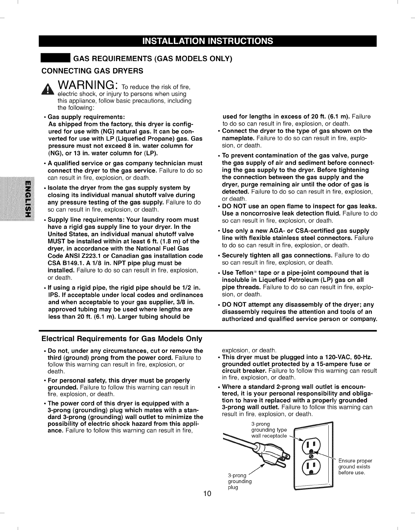
Where a standard 2-prong wall outlet is encoun-
tered, it is your personal responsibility and obliga-
tion to have it replaced with a properly grounded
3-prong wall outlet. Failure to follow this warning can
result in fire, explosion, or death.
3-prong
grounding type
a-prong
grounding
plug
Ensure proper
ground exists
before use.
I I
I I
CONNECTING GAS DRYERS (cont.)
WARNING" To reduce the risk of fire,
electric shock, or injury to persons when using
this appliance, follow basic precautions, including
the following:
• Installation and service must be performed by a
qualified installer, service agency, or the gas
supplier. Failure to do so can result in fire, explosion,
or death.
• Use only a new stainless steel flexible connector
and a new AGA-certified connector. Failure to do
so can result in fire, explosion, or death.
• A gas shutoff valve must be installed within 6 ft.
(1.8 m) of the dryer. Failure to do so can result in fire,
explosion, or death.
• The dryer is configured for Natural Gas when
shipped from the factory. Make sure that the dryer
is equipped with the correct burner nozzle for the
type of gas being used (Natural Gas or Liquefied
Petroleum). Failure to do so can result in fire,
explosion, or death.
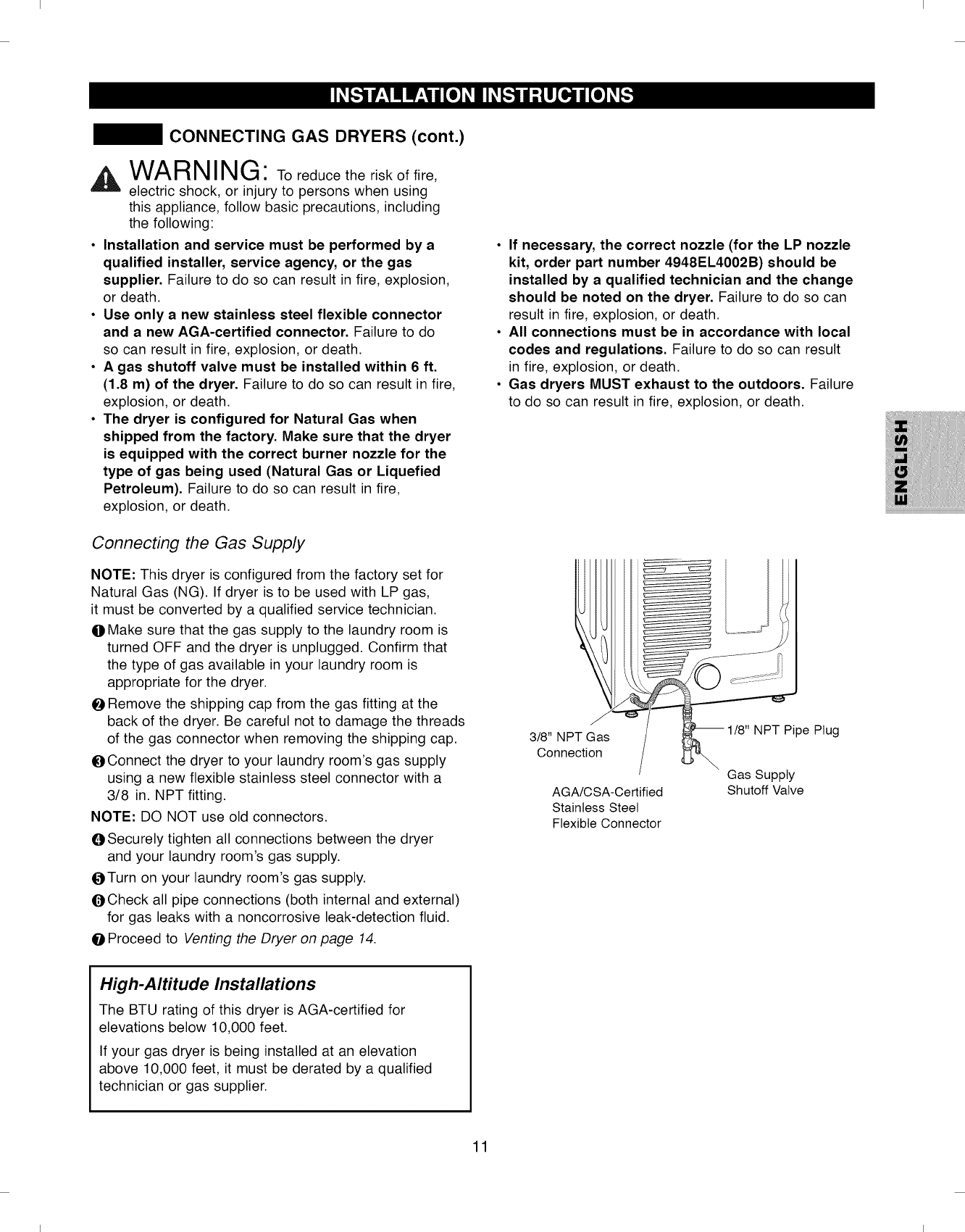
Connecting the Gas Supply
NOTE: This dryer is configured from the factory set for
Natural Gas (NG). If dryer is to be used with LP gas,
it must be converted by a qualified service technician.
OMake sure that the gas supply to the laundry room is
turned OFF and the dryer is unplugged. Confirm that
the type of gas available in your laundry room is
appropriate for the dryer.
ORemove the shipping cap from the gas fitting at the
back of the dryer. Be careful not to damage the threads
of the gas connector when removing the shipping cap.
OConnect the dryer to your laundry room's gas supply
using a new flexible stainless steel connector with a
3/8 in. NPT fitting.
NOTE: DO NOT use old connectors.
OSecurely tighten all connections between the dryer
and your laundry room's gas supply.
OTurn on your laundry room's gas supply.
OCheck all pipe connections (both internal and external)
for gas leaks with a noncorrosive leak-detection fluid.
OProceed to Venting the Dryer on page 14.
•If necessary, the correct nozzle (for the LP nozzle
kit, order part number 4948EL4002B) should be
installed by a qualified technician and the change
should be noted on the dryer. Failure to do so can
result in fire, explosion, or death.
•All connections must be in accordance with local
codes and regulations. Failure to do so can result
in fire, explosion, or death.
• Gas dryers MUST exhaust to the outdoors. Failure
to do so can result in fire, explosion, or death.
3/8" NPT Gas
Connection
AGA/CSA-Certified
Stainless Steel
Flexible Connector
1/8" NPT Pipe Plug
Gas Supply
Shutoff Valve
High-Altitude Installations
The BTU rating of this dryer is AGA-certified for
elevations below 10,000 feet.
If your gas dryer is being installed at an elevation
above 10,000 feet, it must be derated by a qualified
technician or gas supplier.
11
I I
I I
ELECTRICAL REQUIREMENTS
CONNECTING ELECTRIC DRYERS
,A WARNING" To help prevent fire, electric
shock, serious injury, or death, the wiring and
grounding must conform to the latest edition of the
National Electrical Code, ANSI/NFPA 70 and all
applicable local regulations. Please contact a quali-
fied electrician to check your home's wiring and
fuses to ensure that your home has adequate elec-
trical power to operate the dryer.
A \^lAD M I M t'E'_
VV/-_,FII _111_11b_.,1"To reduce the risk of fire,
electric shock, or injury to persons when using
this appliance, follow basic precautions, including
the following:
• Any installation in a manufactured or mobile home must
comply with the Manufactured Home Construction and
Safety Standards Title 24 CFR, Part 32-80 or Standard
CAN/CSAOZ240 MH and local codes and ordinances.
•A 4-wire connection is required for all mobile and
manufactured home installations, as well as all new
construction after January 1, 1996. Failure to do so
can result in fire, explosion, or death.
AWARN IMt__
ii _11b_.,1"To reduce the risk of fire,
electric shock, or injury to persons when using
this appliance, follow basic precautions, including
the following:
This dryer must be connected to a grounded metal,
permanent wiring system, or an equipment ground-
ing conductor must be run with the circuit conduc-
tors and connected to the equipment grounding ter-
minal or lead on the dryer. Failure to do so can result
in fire, explosion, or death.
The dryer has its own terminal block that must be
connected to a separate 240 VAC, 60-Hertz, single
phase circuit, fused at 30 amperes (the circuit must
be fused on both sides of the line). ELECTRICAL
SERVICE FOR THE DRYER SHOULD BE OF THE
MAXIMUM RATE VOLTAGE LISTED ON THE NAME-
PLATE. DO NOT CONNECT DRYER TO 110-, 115-,
OR 120-VOLT CIRCUIT. Heating elements are avail-
able for field installation in dryers which are to be
connected to an electrical service of a different
voltage than that listed on the rating plate. Failure to
follow these instructions can result in fire, explosion, or
death.
If branch circuit to dryer is 15 ft. (4.5 m) or less in
length, use UL (Underwriters Laboratories) listed
No.-10 AWG wire (copper wire only), or as required
by local codes. If over 15 ft. (4.50 m), use UL-listed
No.-8 AWG wire (copper wire only), or as required
by local codes. Allow sufficient slack in wiring so
dryer can be moved from its normal location when
necessary. Failure to do so can result in fire, explosion,
or death.
• The power cord (pigtail) connection between wall
receptacle and dryer terminal block IS NOT sup-
plied with the dryer. Type of pigtail and gauge of
wire must conform to local codes and with instruc-
tions on the following pages. Failure to follow these
instructions can result in fire, explosion, or death
•A4-wire connection is required for all new con-
struction after January 1, 1996. A4-wire connection
must be used where local codes do not permit
grounding through the neutral wire. Failure to do so
can result in fire, explosion, or death.
12
I I
I I
CONNECTING ELECTRIC DRYERS (cont.)
A kWARNING"
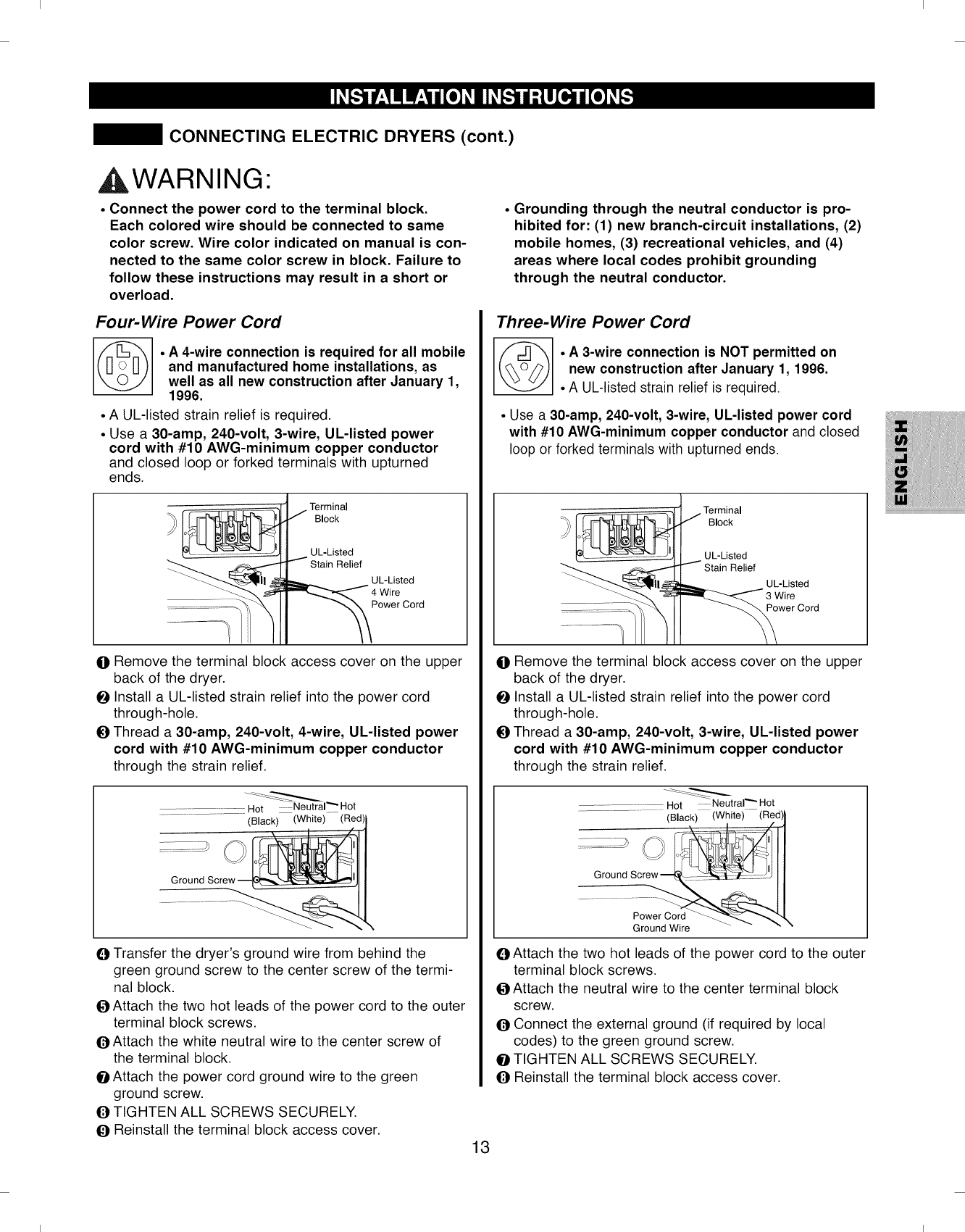
. Connect the power cord to the terminal block.
Each colored wire should be connected to same
color screw. Wire color indicated on manual is con-
nected to the same color screw in block. Failure to
follow these instructions may result in a short or
overload.
Four-Wire Power Cord
©°A4-wire connection is required for all mobile
and manufactured home installations, as
well as all new construction after January 1,
1996.
° A UL-listed strain relief is required.
° Use a 30-amp, 240-volt, 3-wire, UL-listed power
cord with #10 AWG-minimum copper conductor
and closed loop or forked terminals with upturned
ends.
Terminal
Block
UL-Listed
Relief
UL-Listed
Power Cord
ORemove the terminal block access cover on the upper
back of the dryer.
OInstall a UL-listed strain relief into the power cord
through-hole.
OThread a 30-amp, 240-volt, 4-wire, UL-listed power
cord with #10 AWG-minimum copper conductor
through the strain relief.
Hot ............Neutral"" Hot
(Black) (White) (Red)
OTransfer the dryer's ground wire from behind the
green ground screw to the center screw of the termi-
nal block.
OAttach the two hot leads of the power cord to the outer
terminal block screws.
OAttach the white neutral wire to the center screw of
the terminal block.
OAttach the power cord ground wire to the green
ground screw.
OTIGHTEN ALL SCREWS SECURELY.
OReinstall the terminal block access cover.
°Grounding through the neutral conductor is pro-
hibited for: (1) new branch-circuit installations, (2)
mobile homes, (3) recreational vehicles, and (4)
areas where local codes prohibit grounding
through the neutral conductor.
Three-Wire Power Cord
°A 3-wire connection is NOT permitted on
new construction after January 1, 1996.
• A UL-listed strain relief is required.
• Use a 30-amp, 240-volt, 3-wire, UL-listed power cord
with #10 AWG-minimum copper conductor and closed
loop or forked terminals with upturned ends.
Terminal
Block
UL-Listed
Stain Relief
UL-Listed
3 Wire
Power Cord
ORemove the terminal block access cover on the upper
back of the dryer.
OInstall a UL-listed strain relief into the power cord
through-hole.
OThread a 30-amp, 240-volt, 3-wire, UL-listed power
cord with #10 AWG-minimum copper conductor
through the strain relief.
Hot ..........Neutral"" Hot
........................................(Black) (White)-- (Red)}
s2............o........ t
Ground Wire - - " "
OAttach the two hot leads of the power cord to the outer
terminal block screws.
OAttach the neutral wire to the center terminal block
screw.
OConnect the external ground (if required by local
codes) to the green ground screw.
OTIGHTEN ALL SCREWS SECURELY.
OReinstall the terminal block access cover.
13
I I
I I
VENTING THE DRYER
CHECK YOUR EXHAUST SYSTEM FOR
PROBLEMS
The most common cause of dryer problems is poor exhaust venting. Before you install your new dryer, check the
items listed below to make sure you get the best possible performance. This can save you time and money by reducing
cycle times and increasing energy efficiency.
ODIRTY OR DAMAGED EXHAUST DUCTS. Lint builds up in exhaust ducts over time. This decreases the airflow and
makes the dryer work harder. Visually inspect your ducts from both ends and have them cleaned if they have not
been cleaned recently.
WRONG VENT MATERIAL. Check your vent to make sure it is rigid or semi-rigid metal ducting. If your venting is
plastic or flexible foil, have it replace before using the dryer.
O RESTRICTED OR DAMAGED VENT HOOD. Check your vent hood outside. It must be clean and free of lint buildup.
Check the damper and make sure it opens fully and easily.
O EXESSIVELY LONG VENT. Measure the length of your exhaust system and count the elbows. Use the chart of page
14 to see if your duct is too long. If it is too long, have the duct routed to another location that is within the venting
guidelines.
(} DO NOT USE PLASTIC OR FOIL VENTING. The transition duct from your dryer to the wall must be rigid or
semi-rigid metal ducting. If your old transition duct is plastic or foil, REPLACE IT with semi-rigid metal ducting.
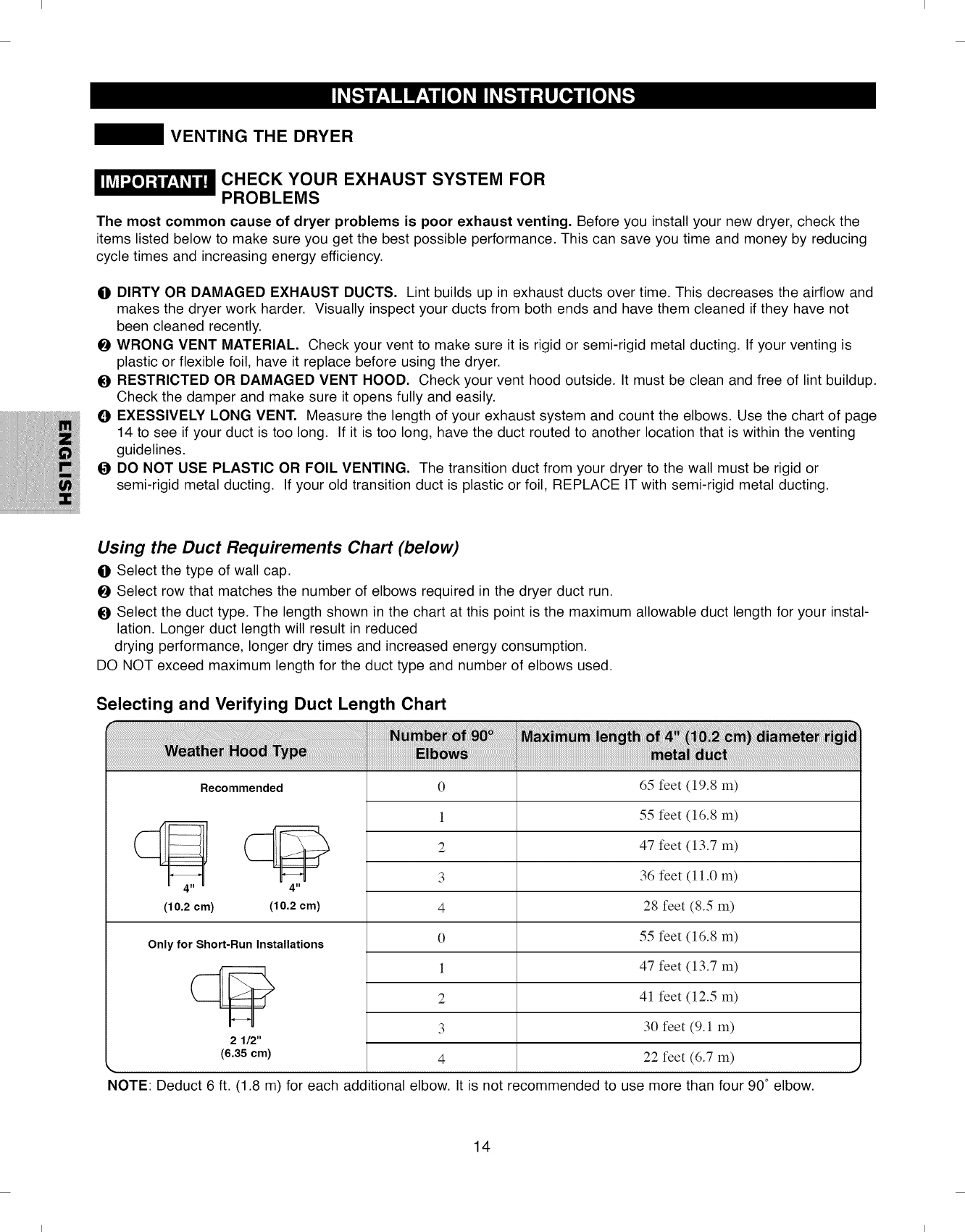
Using the Duct Requirements Chart (below)
O Select the type of wall cap.
Select row that matches the number of elbows required in the dryer duct run.
O Select the duct type. The length shown in the chart at this point is the maximum allowable duct length for your instal-
lation. Longer duct length will result in reduced
drying performance, longer dry times and increased energy consumption.
DO NOT exceed maximum length for the duct type and number of elbows used.
Selecting and Verifying Duct Length Chart
Recommended 065 feet (19.8 m)
4" 4"
(10.2 cm) (10.2 cm)
Only for Short-Run Installations
21/2"
(6.35 cm)
1
2
3
4
0
1
2
3
4
55 feet (16.8 m)
47 feet (13.7 m)
36 feet (11.0 m)
28 feet (8.5 m)
55 feet (16.8 m)
47 feet (13.7 m)
41 feet (12.5 m)
30 feet (9.1 m)
22 feet (6.7 m)
NOTE: Deduct 6 ft. (1.8 m) for each additional elbow. It is not recommended to use more than four 90° elbow.
14
I I
I I
VENTING THE DRYER (cont.)
Routing and Connecting Ductwork
Follow the guidelines below to maximize drying
performance and reduce lint buildup and condensation
in the ductwork.
NOTE: Ductwork and fittings are NOT included and must
be purchased separately.
• Use 4 in. (102mm) diameter rigid or semi rigid metal
ductwork.
• The exhaust duct run should be as short as possible.
• Use as few elbow joints as possible.
• The male end of each section of exhaust duct must
point away from the dryer.
• Use duct tape on all duct joints.
• Insulate ductwork that runs through unheated areas
in order to reduce condensation and lint buildup
on duct surfaces.
• The Total length of flexible metal duct shall not exceed 8
ft.(2.4m)
• In Canada, that only those foil-type flexible ducts, if any,
specifically identified for use with the appliance by the
manufacturer shall be used. In the United States, that
only those foil-type flexible ducts, if any, specifically
identified for use with the appliance by the manufacturer
and that comply with the Outline for Clothes Dryer
Transition Duct, Subject 2158A, shall be used
WARNING" Failure to follow these
guidelines will result in poor performance, product
failure, and/or result in fire or death.
IMPORTANT: Failure to exhaust the dryer per the
guidelines included within these instructions may result
in unsatisfactory dryer performance. All venting and
ductwork beyond the exterior of the dryer is the
responsibility of the consumer. Product failure as
a result of improper venting is not covered by the
manufacturer's warranty.
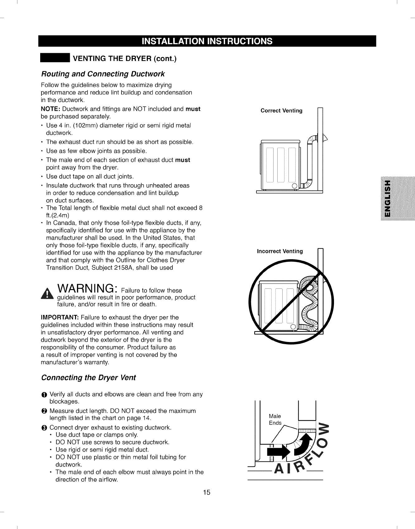
Connecting the Dryer Vent
(
Correct Venting
Incorrect Venting
7' 1
OVerify all ducts and elbows are clean and free from any
blockages. !
OMeasure duct length. DO NOT exceed the maximum
length listed in the chart on page 14. Male
OConnect dryer exhaust to existing ductwork, i
• Use duct tape or clamps only.
• DO NOT use screws to secure ductwork.
• Use rigid or semi rigid metal duct.
• DO NOT use plastic or thin metal foil tubing for
ductwork.
• The male end of each elbow must always point in the
direction of the airflow.
15
O
I I
I I
LEVELING THE DRYER
,A WARNING
•Wear gloves during installation.
• Failure to follow these instructions can result
in injury.
To ensure that the dryer provides optimal drying
performance, it must be level. To minimize vibration,
noise, and unwanted movement, the floor must be
a level, solid surface.
NOTE: Adjust the leveling feet only as far as necessary
to level the dryer. Extending the leveling feet more than
necessary can cause the dryer to vibrate.
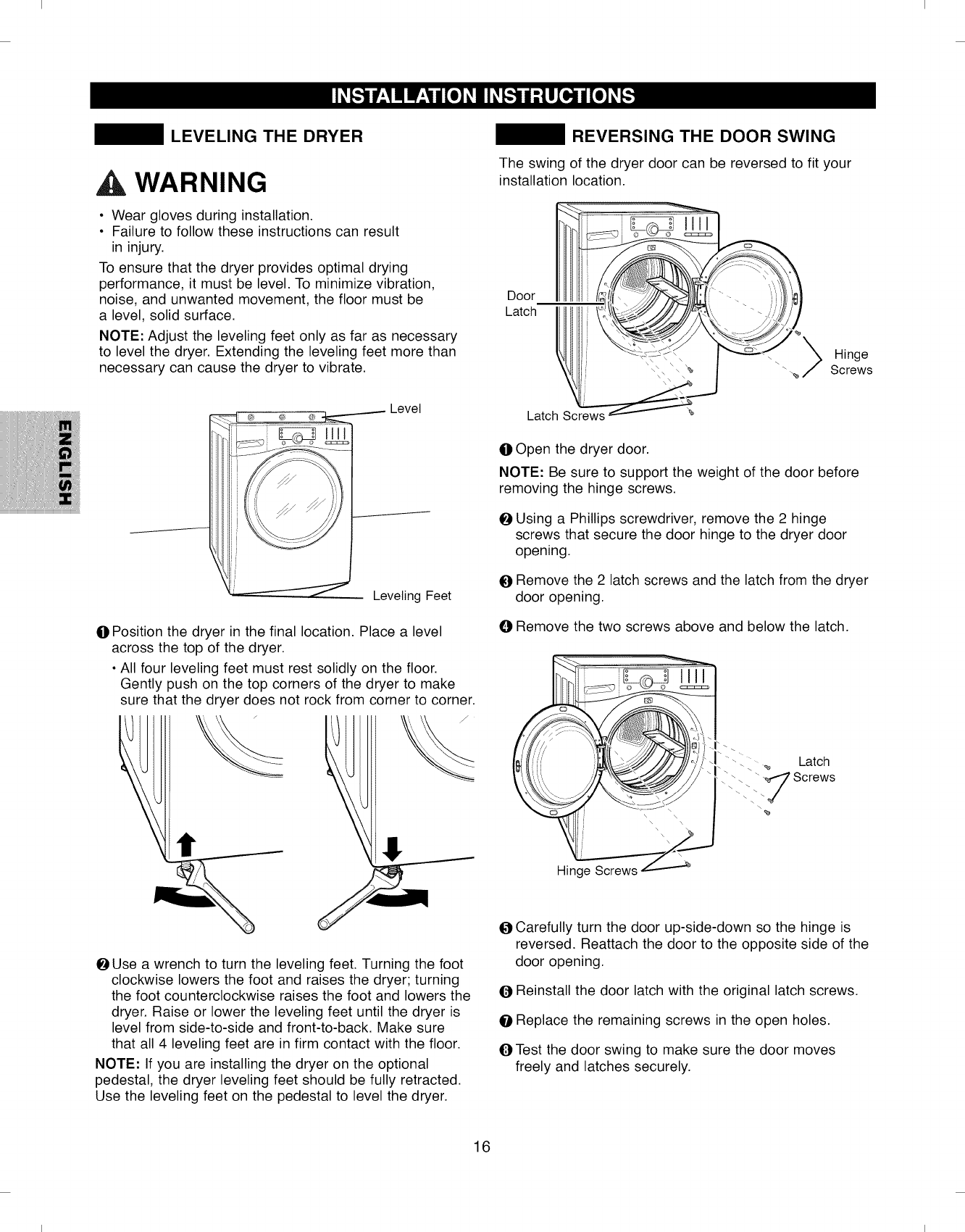
OPosition the dryer in the final location. Place a level
across the top of the dryer.
• All four leveling feet must rest solidly on the floor.
Gently push on the top corners of the dryer to make
sure that the dryer does not rock from corner to corner.
_lUse a wrench to turn the leveling feet. Turning the foot
clockwise lowers the foot and raises the dryer; turning
the foot counterclockwise raises the foot and lowers the
dryer. Raise or lower the leveling feet until the dryer is
level from side-to-side and front-to-back. Make sure
that all 4 leveling feet are in firm contact with the floor.
NOTE: If you are installing the dryer on the optional
pedestal, the dryer leveling feet should be fully retracted.
Use the leveling feet on the pedestal to level the dryer.
REVERSING THE DOOR SWING
The swing of the dryer door can be reversed to fit your
installation location.
Door.
Latch i °_'_
_ Hinge
Screws
Latch Screws _
OOpen the dryer door.
NOTE: Be sure to support the weight of the door before
removing the hinge screws.
Using a Phillips screwdriver, remove the 2 hinge
screws that secure the door hinge to the dryer door
opening.
O Remove the 2 latch screws and the latch from the dryer
door opening.
ORemove the two screws above and below the latch.
,atch
Screws
Carefully turn the door up-side-down so the hinge is
reversed. Reattach the door to the opposite side of the
door opening.
Q Reinstall the door latch with the original latch screws.
OReplace the remaining screws in the open holes.
OTest the door swing to make sure the door moves
freely and latches securely.
16
I I
I I
FINAL INSTALLATION CHECK
Once you have completed the installation of the dryer
and it is in its final location, confirm proper operation with
the following steps and tests.
OIs gas turned ON? (Gas Models only)
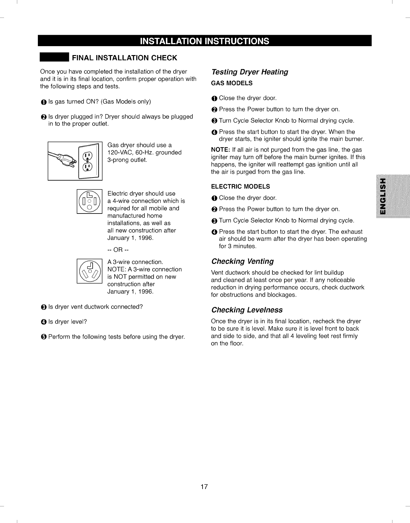
OIs dryer plugged in? Dryer should always be plugged
in to the proper outlet.
Gas dryer should use a
120-VAC, 60-Hz. grounded
3-prong outlet.
@
©
Electric dryer should use
a 4-wire connection which is
required for all mobile and
manufactured home
installations, as well as
all new construction after
January 1, 1996.
-- OR --
A 3-wire connection.
NOTE: A 3-wire connection
is NOT permitted on new
construction after
January 1, 1996.
OIs dryer vent ductwork connected?
OIs dryer level?
OPerform the following tests before using the dryer.
Testing Dryer Heating
GAS MODELS
OClose the dryer door.
OPress the Power button to turn the dryer on.
OTurn Cycle Selector Knob to Normal drying cycle.
OPress the start button to start the dryer. When the
dryer starts, the igniter should ignite the main burner.
NOTE: If all air is not purged from the gas line, the gas
igniter may turn off before the main burner ignites. If this
happens, the igniter will reattempt gas ignition until all
the air is purged from the gas line.
ELECTRIC MODELS
OOlose the dryer door.
OPress the Power button to turn the dryer on.
OTurn Cycle Selector Knob to Normal drying cycle.
OPress the start button to start the dryer. The exhaust
air should be warm after the dryer has been operating
for 3 minutes.
Checking Venting
Vent ductwork should be checked for lint buildup
and cleaned at least once per year. If any noticeable
reduction in drying performance occurs, check ductwork
for obstructions and blockages.
Checking Levelness
Once the dryer is in its final location, recheck the dryer
to be sure it is level. Make sure it is level front to back
and side to side, and that all 4 leveling feet rest firmly
on the floor.
17
I I
I I
WARNING: To reduce the risk of fire, electric shock, or injury to persons, read this entire
manual, including the Important Safety Instructions, before operating this dryer.
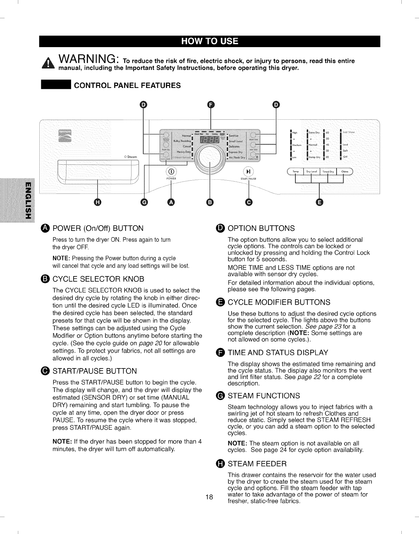
CONTROL PANEL FEATURES
© Steam
0
g
POWER (On/Off) BUTTON
Pressto turn the dryer ON. Press again to turn
the dryer OFF.
NOTE: Pressing the Power button during a cycle
will cancel that cycle and any load settings will be lost.
CYCLE SELECTOR KNOB
The CYCLE SELECTOR KNOB is used to select the
desired dry cycle by rotating the knob in either direc-
tion until the desired cycle LED is illuminated. Once
the desired cycle has been selected, the standard
presets for that cycle will be shown in the display.
These settings can be adjusted using the Cycle
Modifier or Option buttons anytime before starting the
cycle. (See the cycle guide on page 20 for allowable
settings. To protect your fabrics, not all settings are
allowed in all cycles.)
O START/PAUSE BUTTON
Press the START/PAUSE button to begin the cycle.
The display will change, and the dryer will display the
estimated (SENSOR DRY) or set time (MANUAL
DRY) remaining and start tumbling. To pause the
cycle at any time, open the dryer door or press
PAUSE. To resume the cycle where it was stopped,
press START/PAUSE again.
NOTE: If the dryer has been stopped for more than 4
minutes, the dryer will turn off automatically.
18
®OPTION BUTTONS
The option buttons allow you to select additional
cycle options. The controls can be locked or
unlocked by pressing and holding the Control Lock
button for 5 seconds.
MORE TIME and LESS TIME options are not
available with sensor dry cycles.
For detailed information about the individual options,
please see the following pages.
O CYCLE MODIFIER BUTTONS
O
@
Use these buttons to adjust the desired cycle options
for the selected cycle. The lights above the buttons
show the current selection. See page 23 for a
complete description (NOTE: Some settings are
not allowed on some cycles.).
TIME AND STATUS DISPLAY
The display shows the estimated time remaining and
the cycle status. The display also monitors the vent
and lint filter status. See page 22 for a complete
description.
STEAM FUNCTIONS
Steam technology allows you to inject fabrics with a
swirling jet of hot steam to refresh Clothes and
reduce static. Simply select the STEAM REFRESH
cycle, or you can add a steam option to the selected
cycles.
NOTE: The steam option is not available on all
cycles. See page 24 for cycle option availability.
_STEAM FEEDER
This drawer contains the reservoir for the water used
by the dryer to create the steam used for the steam
cycle and options. Fill the steam feeder with tap
water to take advantage of the power of steam for
fresher, static-free fabrics.
I I
I I
OPERATING THE DRYER
POWER
R Extra Dry m 60
Loud
Soft
Off
C
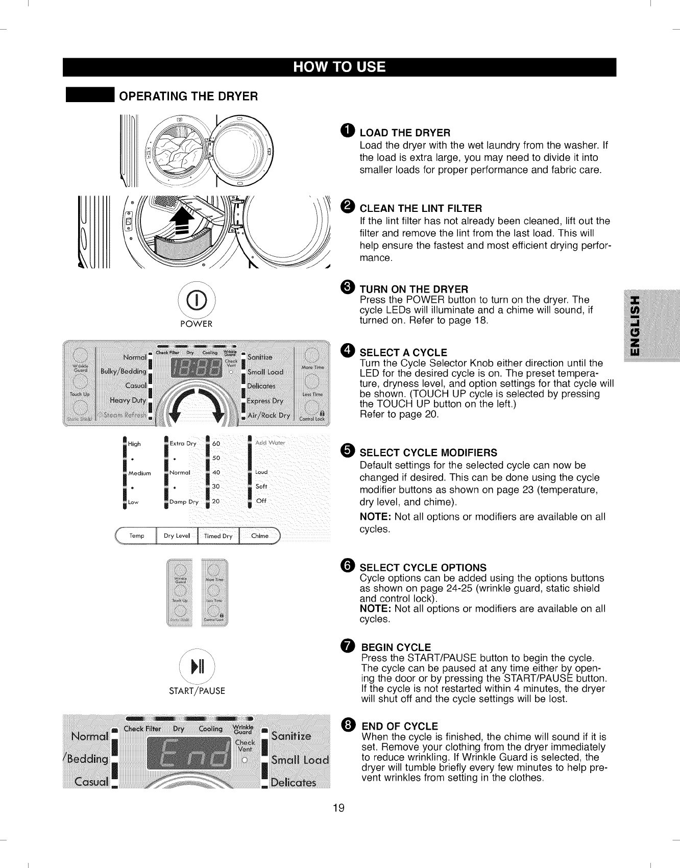
O LOAD THE DRYER
Load the dryer with the wet laundry from the washer. If
the load is extra large, you may need to divide it into
smaller loads for proper performance and fabric care.
jJ
START/PAUSE
OCLEAN THE LINT FILTER
If the lint filter has not already been cleaned, lift out the
filter and remove the lint from the last load. This will
help ensure the fastest and most efficient drying perfor-
mance.
OTURN ON THE DRYER
Press the POWER button to turn on the dryer. The
cycle LEDs will illuminate and a chime will sound, if
turned on. Refer to page 18.
O SELECT A CYCLE
Turn the Cycle Selector Knob either direction until the
LED for the desired cycle is on. The preset tempera-
ture, dryness level, and option settings for that cycle will
be shown. (TOUCH UP cycle is selected by pressing
the TOUCH UP button on the left.)
Refer to page 20.
OSELECT CYCLE MODIFIERS
Default settings for the selected cycle can now be
changed if desired. This can be done using the cycle
modifier buttons as shown on page 23 (temperature,
dry level, and chime).
NOTE: Not all options or modifiers are available on all
cycles.
OSELECT CYCLE OPTIONS
Cycle options can be added using the options buttons
as shown on page 24-25 (wrinkle guard, static shield
and control lock).
NOTE: Not all options or modifiers are available on all
cycles.
BEGIN CYCLE
Press the START/PAUSE button to begin the cycle.
The cycle can be paused at any time either by open-
ing the door or by pressing the START/PAUSE button.
If the cycle is not restarted within 4 minutes, the dryer
will shut off and the cycle settings will be lost.
O END OF CYCLE
When the cycle is finished, the chime will sound if it is
set. Remove your clothing from the dryer immediately
to reduce wrinkling. If Wrinkle Guard is selected, the
dryer will tumble briefly every few minutes to help pre-
vent wrinkles from setting in the clothes.
19
I I
I I
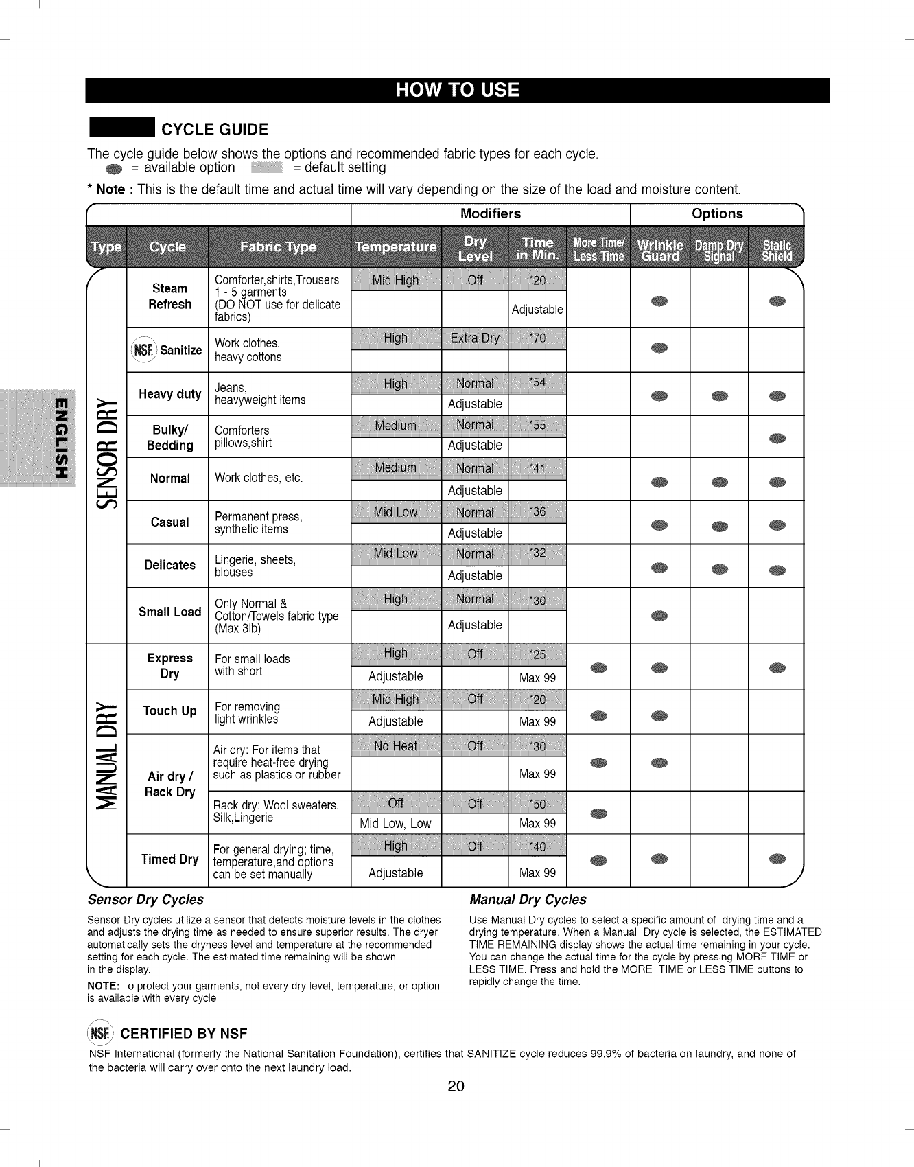
CYCLE GUIDE
The cycle guide below shows the options and recommended fabric types for each cycle.
= available option = default setting
* Note : This is the default time and actual time will vary depending on the size of the load and moisture content.
(Modifiers Options _'
, 0 0,N_
s,eom ....
Refresh (DONOT use for delicate Adjustable _ _
fabrics)
f- " Work clothes,
NSE Sanitize
\/heavy cottons
Jeans, .......
Heavy duty heavyweight items Adjustable _ _
Bulky/ Comforters : _:_ie!i _ !_i,i i ,i115:_ ''" :....
_' Bedding 3illows,shirt Adjustable
......................................................................................................,,,,,,,,,,,,,,,,,,,,,,,,,i!4,,,,,,,,,,,,J,,,
7" Normal Work clothes, etc. _ _
Adjustable
Casual Permanent press, ....
synthetic items Adjustable _ _
Delicates Lingerie, sheets, ....
blouses Adjustable
On, or a,
Small Load Cotton/Towels fabric type
(Max 31b) Adjustable
Touch Up For removing
lightwrinkles _
.,_
--_ Air dry /
Rack Dry
Express For small loads
Dry with short Adjustable Max 99 ....
Adjustable Max 99
_ _:N_ e_ _ _ i0::_:....
Air dry: For items that
recu_reheat-free dryng
such as plastics or rubber Max 99
Rack dry: Wool sweaters,
Silk,Lingerie Mid Low, Low Max 99
For general drying; time,
Timed Dry tem)erature,and options _ _
k,,,,,, can be set manually Adjustable Max 99 J
Sensor Dry Cycles Manual Dry Cycles
Sensor Dry cycles utilize a sensor that detects moisture levels in the clothes
and adjusts the drying time as needed to ensure superior results. The dryer
automatically sets the dryness level and temperature at the recommended
setting for each cycle. The estimated time remaining wil! be shown
in the display.
NOTE: To protect your garments, not every dry level, temperature, or option
is available with every cycle.
Use Manual Dry cycles to select a specific amount of drying time and a
drying temperature. When a Manual Dry cycle is selected, the ESTIMATED
TIME REMAINING display shows the actual time remaining in your cycle.
You can change the actual time for the cycle by pressing MORE TIME or
LESS TIME. Press and hold the MORE TIME or LESS TIME buttons to
rapidly change the time.
iN$_: CERTIFIED BY NSF
NSF International (formerly the National Sanitation Foundation), certifies that SANITIZE cycle reduces 99.9% of bacteria on laundry, and none of
the bacteria will carry over onto the next laundry load.
20
I I
I I
,A WARNING" To reduce the risk of fire, electric shock, or injury to persons, read this entire manual, includ-
ing the Important Safety Instructions, before operating this dryer.
SORTING LOADS
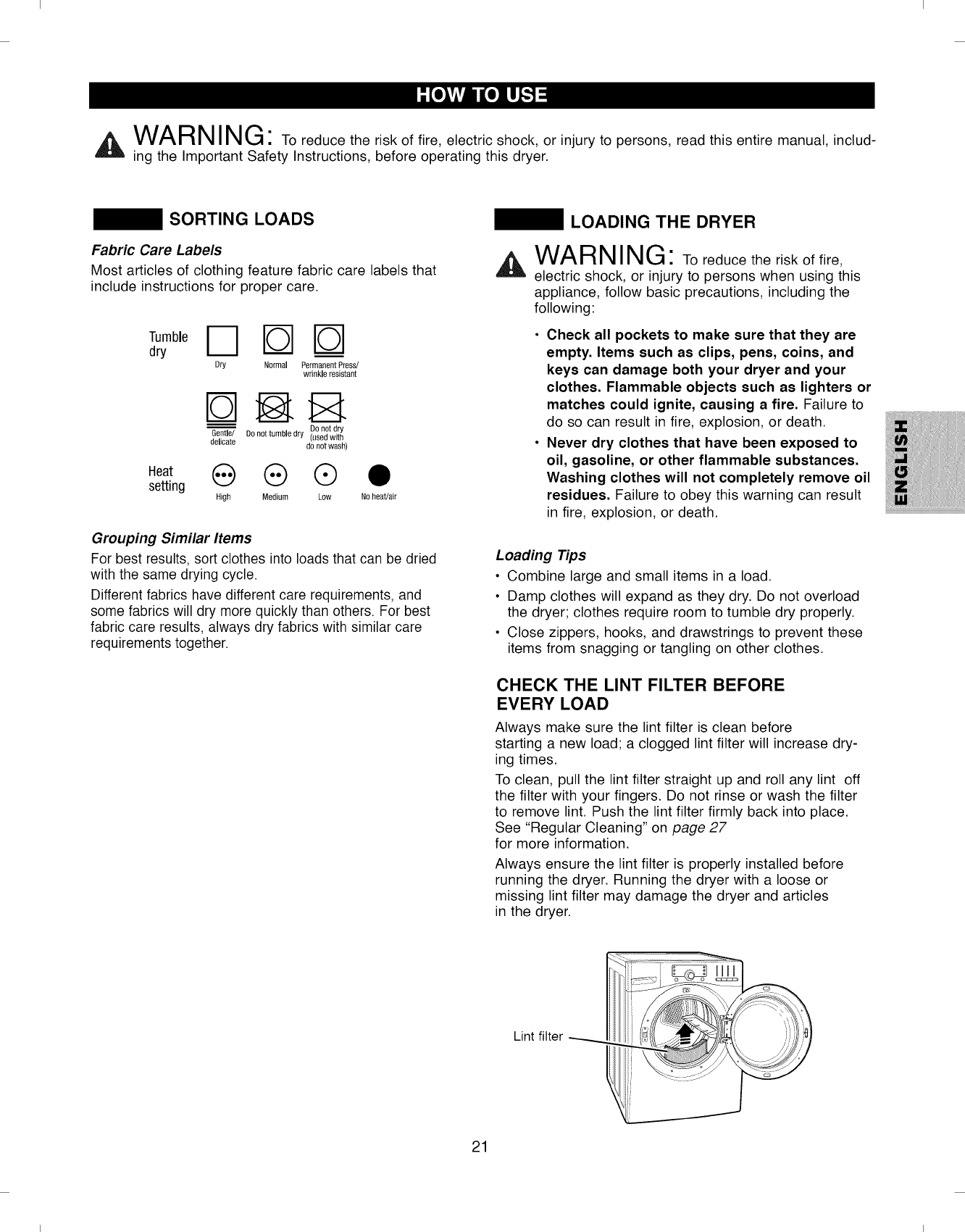
Fabric Care Labels
Most articles of clothing feature fabric care labels that
include instructions for proper care.
Tumble D FOS _-- ]
dry
Dry Normal PermanentPress/
wrinkle resistant
Donot dry
Gentle/ Do not tumble dry (usedwith
delicate do not wash)
Heat _ @ @
setting High Medium Low Noheat/air
Grouping Similar Items
For best results, sort clothes into loads that can be dried
with the same drying cycle.
Different fabrics have different care requirements, and
some fabrics will dry more quickly than others. For best
fabric care results, always dry fabrics with similar care
requirements together.
LOADING THE DRYER
iAIAI_ MiM/"_
VV/_FII_I II_ll, J"TO reduce the risk of fire,
electric shock, or injury to persons when using this
appliance, follow basic precautions, including the
following:
• Check all pockets to make sure that they are
empty. Items such as clips, pens, coins, and
keys can damage both your dryer and your
clothes. Flammable objects such as lighters or
matches could ignite, causing a fire. Failure to
do so can result in fire, explosion, or death.
• Never dry clothes that have been exposed to
oil, gasoline, or other flammable substances.
Washing clothes will not completely remove oil
residues. Failure to obey this warning can result
in fire, explosion, or death.
Loading Tips
• Combine large and small items in a load.
• Damp clothes will expand as they dry. Do not overload
the dryer; clothes require room to tumble dry properly.
• Close zippers, hooks, and drawstrings to prevent these
items from snagging or tangling on other clothes.
CHECK THE LINT FILTER BEFORE
EVERY LOAD
Always make sure the lint filter is clean before
starting a new load; a clogged lint filter will increase dry-
ing times.
To clean, pull the lint filter straight up and roll any lint off
the filter with your fingers. Do not rinse or wash the filter
to remove lint. Push the lint filter firmly back into place.
See "Regular Cleaning" on page 27
for more information.
Always ensure the lint filter is properly installed before
running the dryer. Running the dryer with a loose or
missing lint filter may damage the dryer and articles
in the dryer.
Lint filter
21
I I
I I
TIME AND STATUS DISPLAY
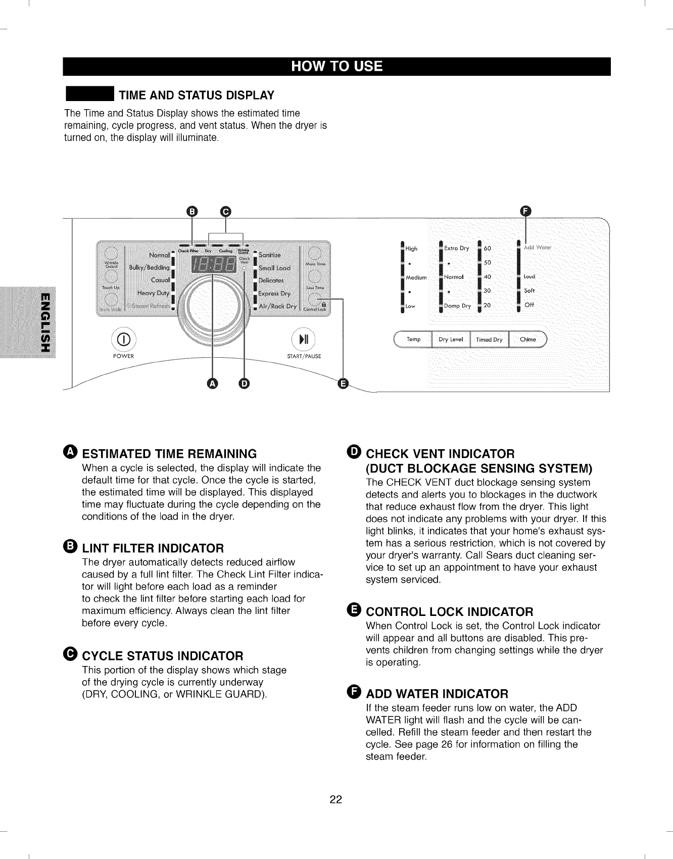
The Time and Status Display shows the estimated time
remaining, cycle progress, and vent status. When the dryer is
turned on, the display will illuminate.
POWER
OESTIMATED TIME REMAINING
When a cycle is selected, the display will indicate the
default time for that cycle. Once the cycle is started,
the estimated time will be displayed. This displayed
time may fluctuate during the cycle depending on the
conditions of the load in the dryer.
LINT FILTER INDICATOR
The dryer automatically detects reduced airflow
caused by a full lint filter. The Check Lint Filter indica-
tor will light before each load as a reminder
to check the lint filter before starting each load for
maximum efficiency. Always clean the lint filter
before every cycle.
CYCLE STATUS INDICATOR
This portion of the display shows which stage
of the drying cycle is currently underway
(DRY, COOLING, or WRINKLE GUARD).
OCHECK VENT INDICATOR
(DUCT BLOCKAGE SENSING SYSTEM)
The CHECK VENT duct blockage sensing system
detects and alerts you to blockages in the ductwork
that reduce exhaust flow from the dryer. This light
does not indicate any problems with your dryer. If this
light blinks, it indicates that your home's exhaust sys-
tem has a serious restriction, which is not covered by
your dryer's warranty. Call Sears duct cleaning ser-
vice to set up an appointment to have your exhaust
system serviced.
CONTROL LOCK INDICATOR
When Control Lock is set, the Control Lock indicator
will appear and all buttons are disabled. This pre-
vents children from changing settings while the dryer
is operating.
ADD WATER INDICATOR
If the steam feeder runs low on water, the ADD
WATER light will flash and the cycle will be can-
celled. Refill the steam feeder and then restart the
cycle. See page 26 for information on filling the
steam feeder.
22
I I
I I
CYCLE MODIFIER BUTTONS
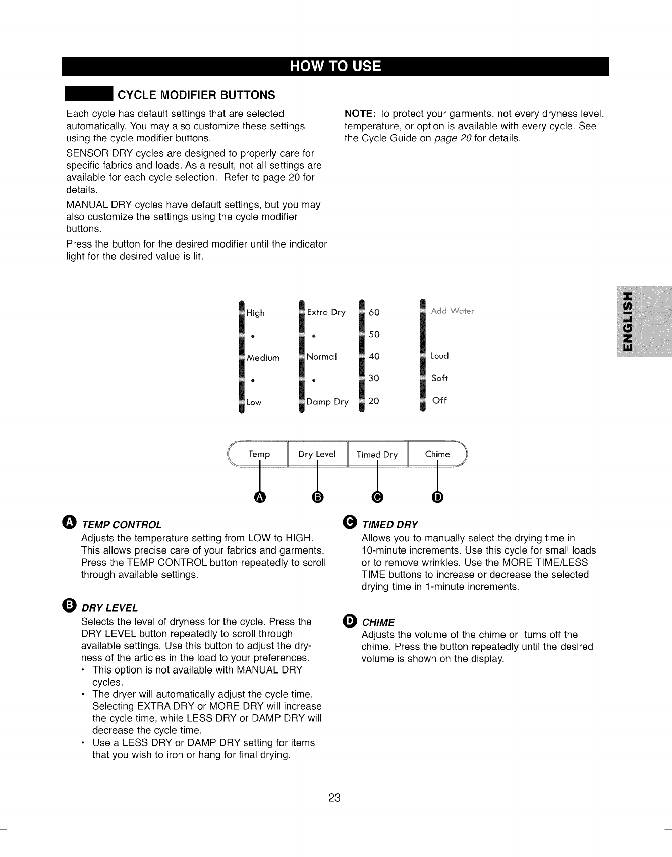
Each cycle has default settings that are selected
automatically. You may also customize these settings
using the cycle modifier buttons.
SENSOR DRY cycles are designed to properly care for
specific fabrics and loads. As a result, not all settings are
available for each cycle selection. Refer to page 20 for
details.
MANUAL DRY cycles have default settings, but you may
also customize the settings using the cycle modifier
buttons.
Press the button for the desired modifier until the indicator
light for the desired value is lit.
NOTE: To protect your garments, not every dryness level,
temperature, or option is available with every cycle. See
the Cycle Guide on page 20 for details.
;High
o
Medium
@
Low
;Extra Dry
®
Normal
®
Damp Dry
60
50
40
30
20
Add _(,,/1 e r
Loud
Soft
Off
Temp Dry Level Timed Dry Chime
I I I
0TEMP CONTROL
Adjusts the temperature setting from LOW to HIGH.
This allows precise care of your fabrics and garments.
Press the TEMP CONTROL button repeatedly to scroll
through available settings.
ODRY LEVEL
Selects the level of dryness for the cycle. Press the
DRY LEVEL button repeatedly to scroll through
available settings. Use this button to adjust the dry-
ness of the articles in the load to your preferences.
• This option is not available with MANUAL DRY
cycles.
• The dryer will automatically adjust the cycle time.
Selecting EXTRA DRY or MORE DRY will increase
the cycle time, while LESS DRY or DAMP DRY will
decrease the cycle time.
• Use a LESS DRY or DAMP DRY setting for items
that you wish to iron or hang for final drying.
TIMED DRY
Allows you to manually select the drying time in
10-minute increments. Use this cycle for small loads
or to remove wrinkles. Use the MORE TIME/LESS
TIME buttons to increase or decrease the selected
drying time in 1-minute increments.
OCHIME
Adjusts the volume of the chime or turns off the
chime. Press the button repeatedly until the desired
volume is shown on the display.
23
I I
I I
CYCLE OPTIONS AND SPECIAL FEATURES
Your dryer features several additional cycle options and special features to meet your individual needs.
features, see the following pages.
For all steam
STEAM FEATURES RACK DRY CYCLE
All steam functions are described on pages 25-26.
To Add Cycle Options to a Cycle:
OTurn on the dryer.
OTurn the Cycle Selector Knob to select the desired
cycle.
OPress the Cycle Option button(s) for the option you
would like to add.
OPress the START Button to start the cycle.
The dryer will start automatically.
WRINKLE GUARD
Selecting this option will tumble the
clothes for a few seconds every few
minutes without heat. This option is
active for 2 hours after the end of the
............................................................cycle, or until the door is opened. This
helps prevent wrinkles in the clothes
caused by lying in the bottom of the drum
when you can't be there to remove them
immediately after the cycle is completed.
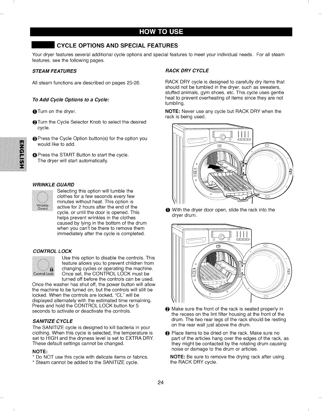
RACK DRY cycle is designed to carefully dry items that
should not be tumbled in the dryer, such as sweaters,
stuffed animals, gym shoes, etc. This cycle uses gentle
heat to prevent overheating of items since they are not
tumbling.
NOTE: Never use any cycle but RACK DRY when the
rack is being used.
o o
OWith the dryer door open, slide the rack into the
dryer drum.
CONTROL LOCK
Use this option to disable the controls. This
feature allows you to prevent children from
changing cycles or operating the machine.
Once set, the CONTROL LOCK must be
turned off before the controls can be used.
Once the washer has shut off, the power button will allow
the machine to be turned on, but the controls will still be
locked. When the controls are locked, "CL" will be
displayed alternately with the estimated time remaining.
Press and hold the CONTROL LOCK button for 5
seconds to activate or deactivate the controls.
SANITIZE CYCLE
The SANITIZE cycle is designed to kill bacteria in your
clothing. When this cycle is selected, the temperature is
set to HIGH and the dryness level is set to EXTRA DRY.
These default settings cannot be changed.
NOTE:
* Do NOT use this cycle with delicate items or fabrics.
* Steam cannot be added to the SANITIZE cycle.
OMake sure the front of the rack is seated properly in
the recess on the lint filter housing at the front of the
drum. The two rear legs of the rack should be resting
on the rear wall just above the drum.
OPlace items to be dried on the rack. Make sure no
part of the articles hang over the edges of the rack, as
they might be contacted by the rotating drum causing
noise or damage to the drum or articles.
NOTE: Be sure to remove the drying rack after using
the RACK DRY cycle.
24
I I
I I
STEAM FUNCTIONS
,A WARNING"
• Do not open the dryer door during Steam Cycles.
Steam can cause severe burns.
• Do not fill the steam feeder with gasoline, dry-
cleaning solvents, or other flammable or explosive
substances.They give off vapors that could
explode.
• Do not drink water from the steam feeder.
• Do not fill the steam feeder with hot water (over
86°F/30°C).
• Do not touch the steam nozzle in the drum during
or after the steam cycle.
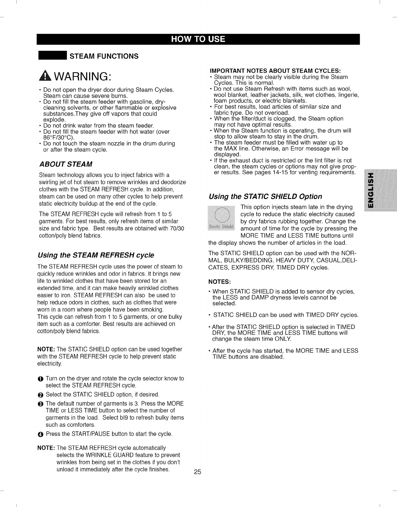
ABOUT STEAM
Steam technology allows you to inject fabrics with a
swirling jet of hot steam to remove wrinkles and deodorize
clothes with the STEAM REFRESH cycle. In addition,
steam can be used on many other cycles to help prevent
static electricity buildup at the end of the cycle.
The STEAM REFRESH cycle will refresh from 1 to 5
garments. For best results, only refresh items of similar
size and fabric type. Best results are obtained with 70/30
cotton/poly blend fabrics.
Using the STEAM REFRESH cycle
The STEAM REFRESH cycle uses the power of steam to
quickly reduce wrinkles and odor in fabrics. It brings new
life to wrinkled clothes that have been stored for an
extended time, and it can make heavily wrinkled clothes
easier to iron. STEAM REFRESH can also be used to
help reduce odors in clothes, such as clothes that were
worn in a room where people have been smoking.
This cycle can refresh from 1 to 5 garments, or one bulky
item such as a comforter. Best results are achieved on
cotton/poly blend fabrics.
NOTE: The STATIC SHIELD option can be used together
with the STEAM REFRESH cycle to help prevent static
electricity.
OTurn on the dryer and rotate the cycle selector know to
select the STEAM REFRESH cycle.
OSelect the STATIC SHIELD option, if desired.
OThe default number of garments is 3. Press the MORE
TIME or LESS TIME button to select the number of
garments in the load. Select b19to refresh bulky items
such as comforters.
OPress the START/PAUSE button to start the cycle.
NOTE: The STEAM REFRESH cycle automatically
selects the WRINKLE GUARD feature to prevent
wrinkles from being set in the clothes if you don't
unload it immediately after the cycle finishes. 25
IMPORTANT NOTES ABOUT STEAM CYCLES:
• Steam may not be clearly visible during the Steam
Cycles. This is normal.
• Do not use Steam Refresh with items such as wool,
wool blanket, leather jackets, silk, wet clothes, lingerie,
foam products, or electric blankets.
• For best results, load articles of similar size and
fabric type. Do not overload.
• When the filter/duct is clogged, the Steam option
may not have optimal results.
• When the Steam function is operating, the drum will
stop to allow steam to stay in the drum.
• The steam feeder must be filled with water up to
the MAX line. Otherwise, an Error message will be
displayed.
• If the exhaust duct is restricted or the lint filter is not
clean, the steam cycles or options may not give prop-
er results. See pages 14-15 for venting requirements.
Using the STATIC SHIELD Option
This option injects steam late in the drying
cycle to reduce the static electricity caused
by dry fabrics rubbing together. Change the
amount of time for the cycle by pressing the
MORE TIME and LESS TIME buttons until
the display shows the number of articles in the load.
The STATIC SHIELD option can be used with the NOR-
MAL, BULKY/BEDDING, HEAVY DUTY, CASUAL,DELI-
CATES, EXPRESS DRY, TIMED DRY cycles.
NOTES:
• When STATIC SHIELD is added to sensor dry cycles,
the LESS and DAMP dryness levels cannot be
selected.
• STATIC SHIELD can be used with TIMED DRY cycles.
• After the STATIC SHIELD option is selected in TIMED
DRY, the MORE TIME and LESS TIME buttons will
change the steam time ONLY.
• After the cycle has started, the MORE TIME and LESS
TIME buttons are disabled.
I I
I I
STEAM FUNCTIONS
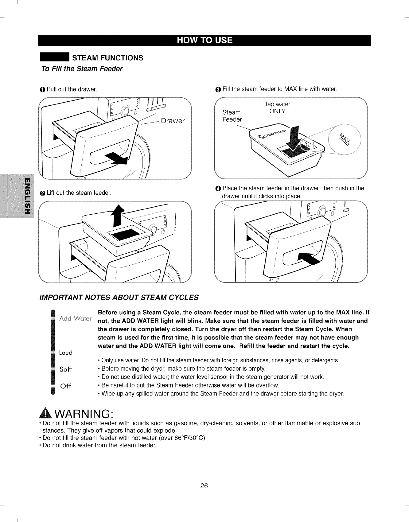
To Fill the Steam Feeder
0Pull out the drawer. 0Fill the steam feeder to MAX line with water.
fTap water
Steam ONLY
Feeder
0Lift out the steam feeder. 0Place the steam feeder in the drawer; then push in the
drawer until it clicks into place.
IMPORTANT NOTES ABOUT STEAM CYCLES
Add '_Wa'ter
Loud
Soft
Off
Before using a Steam Cycle, the steam feeder must be filled with water up to the MAX line. If
not, the ADD WATER light will blink. Make sure that the steam feeder is filled with water and
the drawer is completely closed. Turn the dryer off then restart the Steam Cycle. When
steam is used for the first time, it is possible that the steam feeder may not have enough
water and the ADD WATER light will come one. Refill the feeder and restart the cycle.
•Only use water. Do not fill the steam feeder with foreign substances, rinse agents, or detergents.
• Before moving the dryer, make sure the steam feeder is empty.
• Do not use distilled water; the water level sensor in the steam generator will not work.
• Be careful to put the Steam Feeder otherwise water will be overflow.
• Wipe up any spilled water around the Steam Feeder and the drawer before starting the dryer.
,A WARNING"
• Do not fill the steam feeder with liquids such as gasoline, dry-cleaning solvents, or other flammable or explosive sub
stances. They give off vapors that could explode.
• Do not fill the steam feeder with hot water (over 86°F/30°C).
• Do not drink water from the steam feeder.
26
I I
I I
I^I^DM I M('_
AVV/-_nl_lll_lkJ" To reduce the risk of fire, electric shock, or injury to persons when using
this appliance, follow basic precautions, including the following:
• Unplug the dryer before cleaning to avoid the risk of electric shock. Failure to follow this warning
can cause serious injury, fire, electrical shock, or death.
• Never use harsh chemicals, abrasive cleaners, or solvents to clean the dryer. They will damage the finish.
REGULAR CLEANING
Cleaning the Exterior
Proper care of your dryer can extend its life. The outside
of the machine can be cleaned with warm water and a
mild, nonabrasive household detergent. Immediately
wipe off any spills with a soft, damp cloth.
IMPORTANT: Do not use methylated spirits, solvents,
or similar products.
NEVER use steel wool or abrasive cleansers because
they can damage the surface.
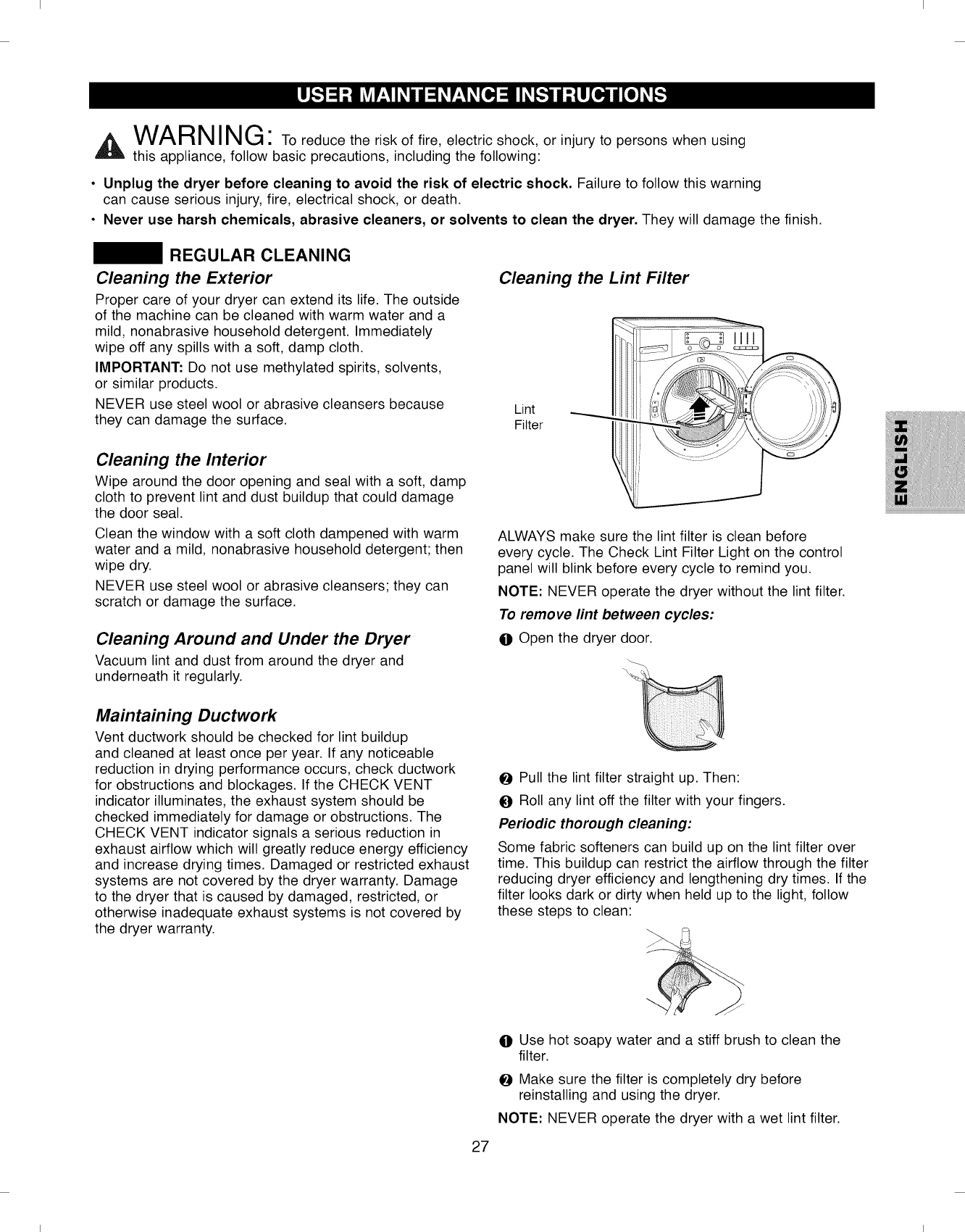
Cleaning the Lint Filter
Lint
Filter
Cleaning the Interior
Wipe around the door opening and seal with a soft, damp
cloth to prevent lint and dust buildup that could damage
the door seal.
Clean the window with a soft cloth dampened with warm
water and a mild, nonabrasive household detergent; then
wipe dry.
NEVER use steel wool or abrasive cleansers; they can
scratch or damage the surface.
Cleaning Around and Under the Dryer
Vacuum lint and dust from around the dryer and
underneath it regularly.
Maintaining Ductwork
Vent ductwork should be checked for lint buildup
and cleaned at least once per year. If any noticeable
reduction in drying performance occurs, check ductwork
for obstructions and blockages. If the CHECK VENT
indicator illuminates, the exhaust system should be
checked immediately for damage or obstructions. The
CHECK VENT indicator signals a serious reduction in
exhaust airflow which will greatly reduce energy efficiency
and increase drying times. Damaged or restricted exhaust
systems are not covered by the dryer warranty. Damage
to the dryer that is caused by damaged, restricted, or
otherwise inadequate exhaust systems is not covered by
the dryer warranty.
ALWAYS make sure the lint filter is clean before
every cycle. The Check Lint Filter Light on the control
panel will blink before every cycle to remind you.
NOTE: NEVER operate the dryer without the lint filter.
To remove lint between cycles:
O Open the dryer door.
Pull the lint filter straight up. Then:
O Roll any lint off the filter with your fingers.
Periodic thorough cleaning:
Some fabric softeners can build up on the lint filter over
time. This buildup can restrict the airflow through the filter
reducing dryer efficiency and lengthening dry times. If the
filter looks dark or dirty when held up to the light, follow
these steps to clean:
27
O Use hot soapy water and a stiff brush to clean the
filter.
Make sure the filter is completely dry before
reinstalling and using the dryer.
NOTE: NEVER operate the dryer with a wet lint filter.
I I
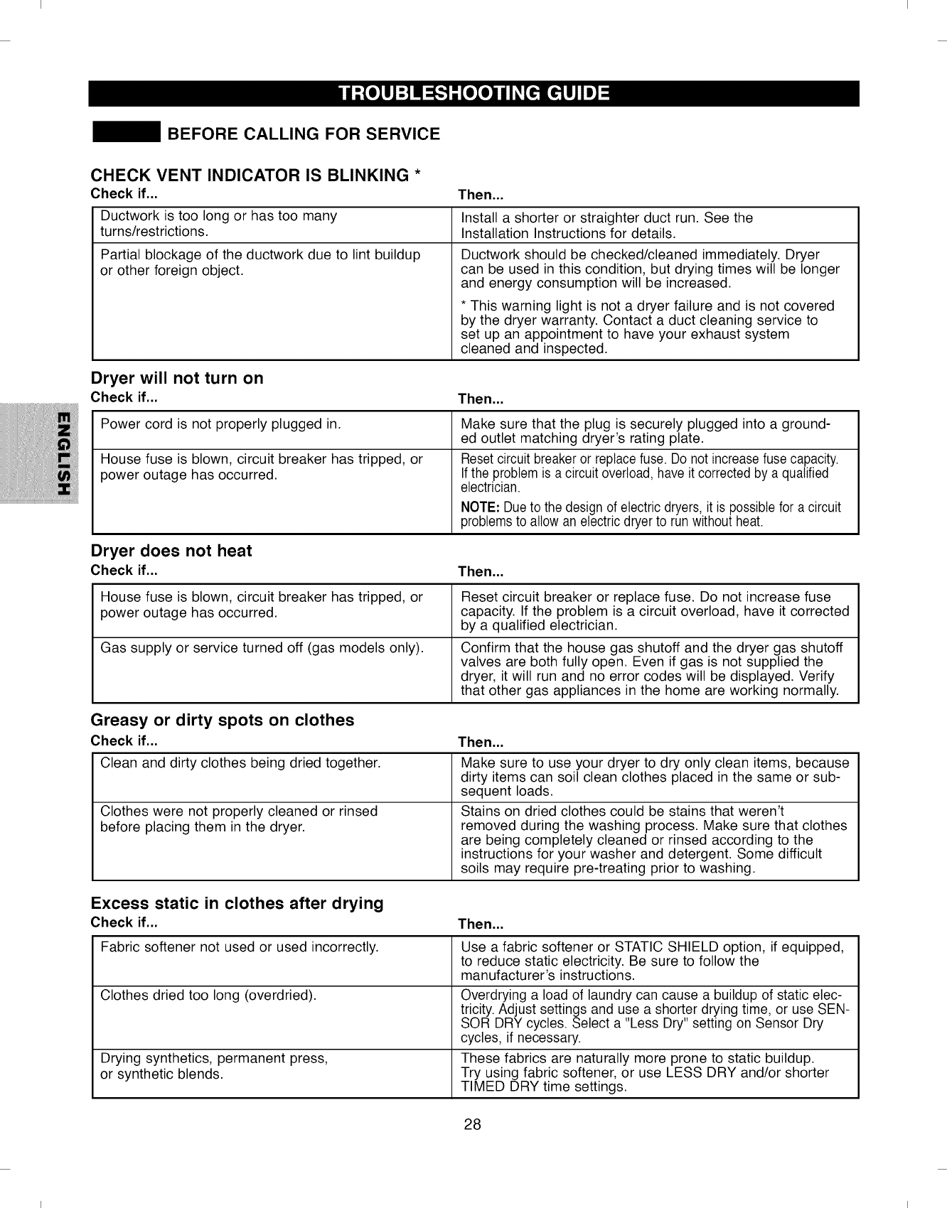
I I
BEFORE CALLING FOR SERVICE
CHECK VENT INDICATOR IS BLINKING *
Check if...
Ductwork is too long or has too many
turns/restrictions.
Partial blockage of the ductwork due to lint buildup
or other foreign object.
Then...
Install a shorter or straighter duct run. See the
Installation Instructions for details.
Ductwork should be checked/cleaned immediately. Dryer
can be used in this condition, but drying times will be longer
and energy consumption will be increased.
* This warning light is not a dryer failure and is not covered
by the dryer warranty. Contact a duct cleaning service to
set up an appointment to have your exhaust system
cleaned and inspected.
Dryer will not turn on
Check if... Then...
Power cord is not properly plugged in.
House fuse is blown, circuit breaker has tripped, or
power outage has occurred.
Dryer does not heat
Check if...
House fuse is blown, circuit breaker has tripped, or
power outage has occurred.
Gas supply or service turned off (gas models only).
Make sure that the plug is securely plugged into a ground-
ed outlet matching dryer's rating plate.
Reset circuit breaker or replace fuse. Do not increase fuse capacity.
If the problem is a circuit overload, have it corrected by a qualified
electrician.
NOTE: Due to the design of electric dryers, it is possible for a circuit
problemsto allow an electricdryer to run without heat.
Then...
Reset circuit breaker or replace fuse. Do not increase fuse
capacity. If the problem is a circuit overload, have it corrected
by a qualified electrician.
Confirm that the house gas shutoff and the dryer gas shutoff
valves are both fully open. Even if gas is not supplied the
dryer, it will run and no error codes will be displayed. Verify
that other gas appliances in the home are working normally.
Greasy or dirty spots on clothes
Check if... Then...
Clean and dirty clothes being dried together.
Clothes were not properly cleaned or rinsed
before placing them in the dryer.
Make sure to use your dryer to dry only clean items, because
dirty items can soil clean clothes placed in the same or sub-
sequent loads.
Stains on dried clothes could be stains that weren't
removed during the washing process. Make sure that clothes
are being completely cleaned or rinsed according to the
instructions for your washer and detergent. Some difficult
soils may require pre-treating prior to washing.
Excess static in clothes after drying
Check if...
Fabric softener not used or used incorrectly.
Clothes dried too long (overdried).
Drying synthetics, permanent press,
or synthetic blends.
28
Then,..
Use a fabric softener or STATIC SHIELD option, if equipped,
to reduce static electricity. Be sure to follow the
manufacturer's instructions.
Overdrying a load of laundry can cause a buildup of static elec-
tricity. Adjust settings and use a shorter drying time, or use SEN-
SOR DRY cycles. Select a "Less Dry" setting on Sensor Dry
cycles, if necessary.
These fabrics are naturally more prone to static buildup.
Try using fabric softener, or use LESS DRY and/or shorter
TIMED DRY time settings.
I I
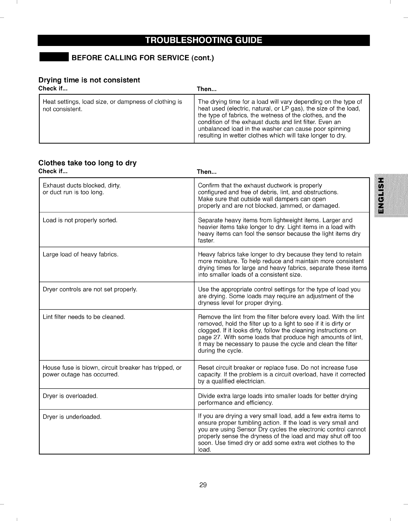
I I
BEFORE CALLING FOR SERVICE (cont.)
Drying time is not consistent
Check if... Then...
Heat settings, load size, or dampness of clothing is
not consistent. The drying time for a load will vary depending on the type of
heat used (electric, natural, or LP gas), the size of the load,
the type of fabrics, the wetness of the clothes, and the
condition of the exhaust ducts and lint filter. Even an
unbalanced load in the washer can cause poor spinning
resulting in wetter clothes which will take longer to dry.
Clothes take too long to dry
Check if...
Exhaust ducts blocked, dirty,
or duct run is too long.
Load is not properly sorted.
Large load of heavy fabrics.
Dryer controls are not set properly.
Lint filter needs to be cleaned.
House fuse is blown, circuit breaker has tripped, or
power outage has occurred.
Then,,,
Confirm that the exhaust ductwork is properly
configured and free of debris, lint, and obstructions.
Make sure that outside wall dampers can open
properly and are not blocked, jammed, or damaged.
Separate heavy items from lightweight items. Larger and
heavier items take longer to dry. Light items in a load with
heavy items can fool the sensor because the light items dry
faster.
Heavy fabrics take longer to dry because they tend to retain
more moisture. To help reduce and maintain more consistent
drying times for large and heavy fabrics, separate these items
into smaller loads of a consistent size.
Use the appropriate control settings for the type of load you
are drying. Some loads may require an adjustment of the
dryness level for proper drying.
Remove the lint from the filter before every load. With the lint
removed, hold the filter up to a light to see if it is dirty or
clogged. If it looks dirty, follow the cleaning instructions on
page 27. With some loads that produce high amounts of lint,
it may be necessary to pause the cycle and clean the filter
during the cycle.
Reset circuit breaker or replace fuse. Do not increase fuse
capacity. If the problem is a circuit overload, have it corrected
by a qualified electrician.
Dryer is overloaded. Divide extra large loads into smaller loads for better drying
performance and efficiency.
Dryer is underloaded. If you are drying a very small load, add a few extra items to
ensure proper tumbling action. If the load is very small and
you are using Sensor Dry cycles the electronic control cannot
properly sense the dryness of the load and may shut off too
soon. Use timed dry or add some extra wet clothes to the
load.
29
I I
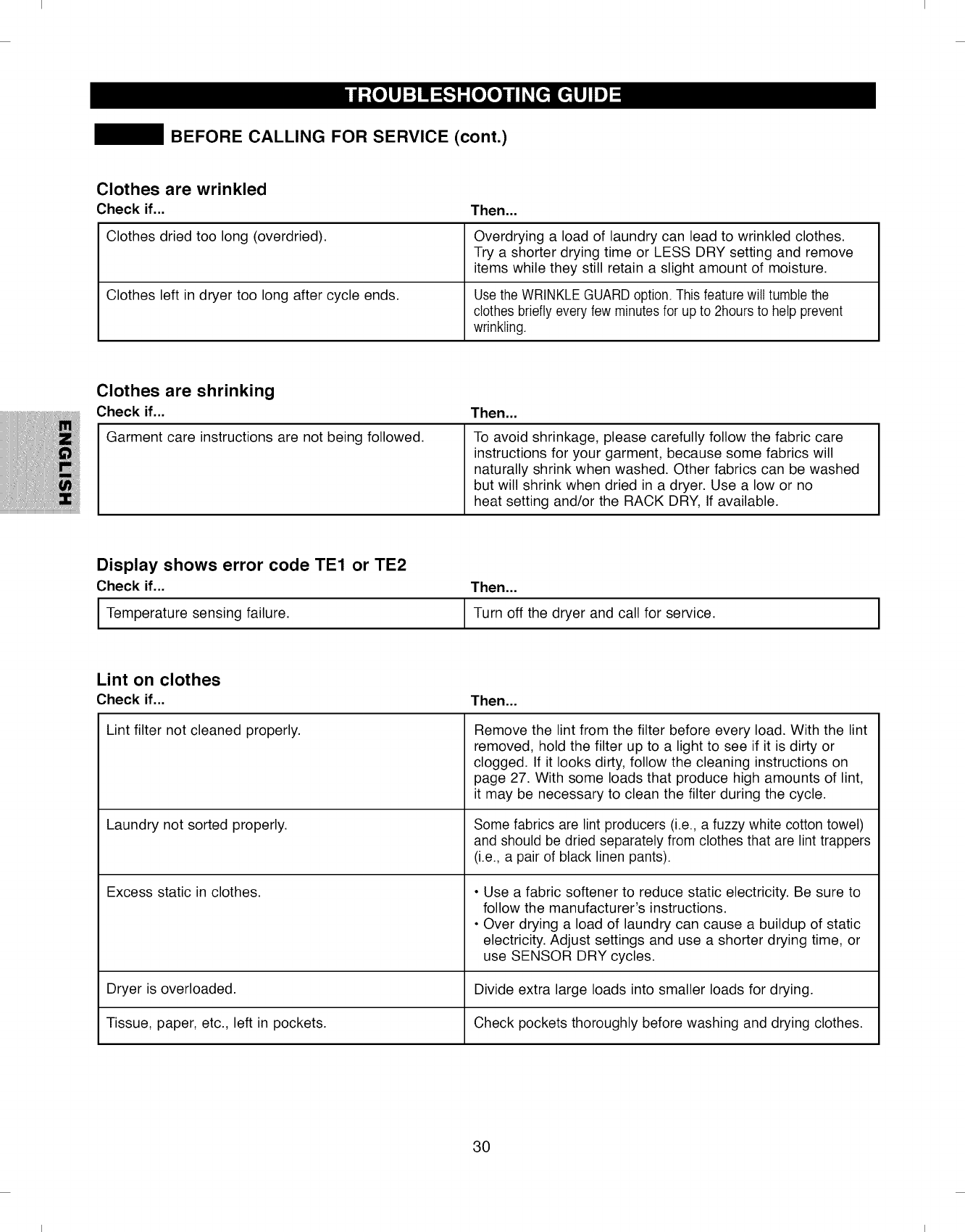
I I
BEFORE CALLING FOR SERVICE (cont.)
Clothes are wrinkled
Check if...
Clothes dried too long (overdried).
Clothes left in dryer too long after cycle ends.
Then...
Overdrying a load of laundry can lead to wrinkled clothes.
Try a shorter drying time or LESS DRY setting and remove
items while they still retain a slight amount of moisture.
Usethe WRINKLEGUARD option. This feature wilt tumble the
clothes briefly every few minutes for up to 2hours to help 3revent
wrinkling.
Clothes are shrinking
Check if...
Garment care instructions are not being followed.
Then...
To avoid shrinkage, please carefully follow the fabric care
instructions for your garment, because some fabrics will
naturally shrink when washed. Other fabrics can be washed
but will shrink when dried in a dryer. Use a low or no
heat setting and/or the RACK DRY, If available.
Display shows error code TEl or TE2
Check if...
I Temperature sensing failure.
Then...
Turn off the dryer and call for service.
Lint on clothes
Check if...
Lint filter not cleaned properly.
Laundry not sorted properly.
Excess static in clothes.
Then...
Remove the lint from the filter before every load. With the lint
removed, hold the filter up to a light to see if it is dirty or
clogged. If it looks dirty, follow the cleaning instructions on
page 27. With some loads that produce high amounts of lint,
it may be necessary to clean the filter during the cycle.
Some fabrics are lint producers (i.e., a fuzzy white cotton towel)
and should be dried separately from clothes that are lint trappers
(i.e., a pair of black linen pants).
• Use a fabric softener to reduce static electricity. Be sure to
follow the manufacturer's instructions.
• Over drying a load of laundry can cause a buildup of static
electricity. Adjust settings and use a shorter drying time, or
use SENSOR DRY cycles.
Dryer is overloaded. Divide extra large loads into smaller loads for drying.
Tissue, paper, etc., left in pockets. Check pockets thoroughly before washing and drying clothes.
30
I I
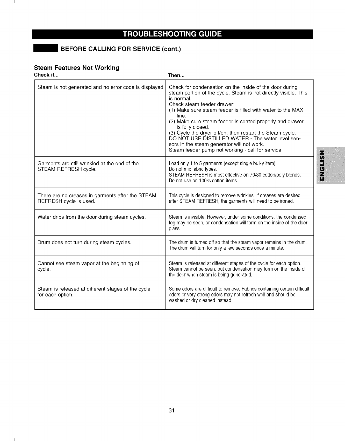
I I
BEFORE CALLING FOR SERVICE (cont.)
Steam Features Not Working
Check if... Then...
Steam is not generated and no error code is displayed
Garments are still wrinkled at the end of the
STEAM REFRESH cycle.
There are no creases in garments after the STEAM
REFRESH cycle is used.
Water drips from the door during steam cycles.
Drum does not turn during steam cycles.
Cannot see steam vapor at the beginning of
cycle.
Steam is released at different stages of the cycle
for each option.
Check for condensation on the inside of the door during
steam portion of the cycle. Steam is not directly visible. This
is normal.
Check steam feeder drawer:
(1) Make sure steam feeder is filled with water to the MAX
line.
(2) Make sure steam feeder is seated properly and drawer
is fully closed.
(3) Cycle the dryer off/on, then restart the Steam cycle.
DO NOT USE DISTILLED WATER - The water level sen-
sors in the steam generator will not work.
Steam feeder pump not working - call for service.
Load only 1 to 5 garments (exceptsingle bulky item).
Do not mix fabric types.
STEAM REFRESHis most effective on 70/30 cotton/poly blends.
Do not use on 100% cotton items.
This cycle is designed to remove wrinkles. If creases are desired
after STEAM REFRESH, the garments will need to be ironed.
Steam is invisible. However, undersome conditions,the condensed
fog may be seen, or condensation will form on the inside of the door
glass.
The drum is turned off so that the steam vapor remains in the drum.
The drum will turn for only a few seconds once a minute.
Steam is released at different stages of the cycle for each option.
Steam cannot be seen, but condensation may form on the inside of
the door when steam is being generated.
Some odors are difficult to remove. Fabrics containing certain difficult
odors or very strong odors may not refresh well and should be
washed or dry cleaned instead.
31
I I
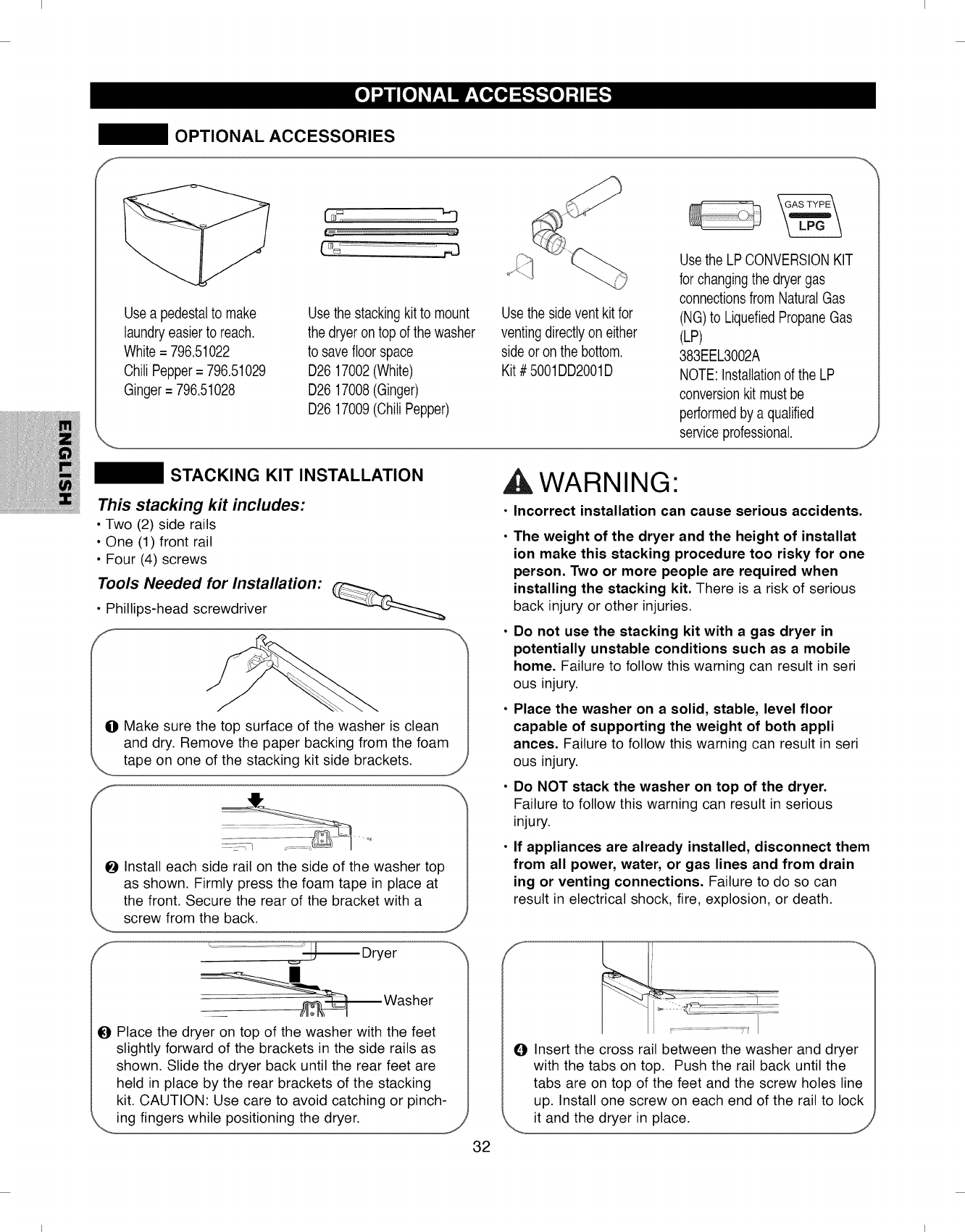
I I
OPTIONAL ACCESSORIES
Usea pedestalto make
laundryeasier to reach.
White = 796.51022
Chili Pepper= 796.51029
Ginger = 796.51028
"'3
Use the stacking kitto mount
the dryer ontop of the washer
to savefloor space
D26 17002(White)
D26 17008(Ginger)
D26 17009(Chili Pepper)
Usethe side vent kit for
venting directlyon either
side or on the bottom.
Kit # 5001DD2001D
Usethe LP CONVERSIONKIT
for changingthe dryer gas
connectionsfrom NaturalGas
(NG)to LiquefiedPropaneGas
(LP)
383EEL3002A
NOTE: Installationof the LP
conversion kit must be
performedby a qualified
'_ service professional. J
STACKING KIT INSTALLATION
This stacking kit includes:
• Two (2) side rails
• One (1) front rail
• Four (4) screws
Tools Needed for Installation:
• Phillips-head screwdriver
OMake sure the top surface of the washer is clean
and dry. Remove the paper backing from the foam
tape on one of the stacking kit side brackets.
OInstall each side rail on the side of the washer top
as shown. Firmly press the foam tape in place at
the front. Secure the rear of the bracket with a
screw from the back. J
..........................._ Dryer
Washer
OPlace the dryer on top of the washer with the feet
slightly forward of the brackets in the side rails as
shown. Slide the dryer back until the rear feet are
held in place by the rear brackets of the stacking
kit. CAUTION: Use care to avoid catching or pinch-
ing fingers while positioning the dryer.
WARNING"
•Incorrect installation can cause serious accidents.
The weight of the dryer and the height of installat
ion make this stacking procedure too risky for one
person. Two or more people are required when
installing the stacking kit. There is a risk of serious
back injury or other injuries.
Do not use the stacking kit with a gas dryer in
potentially unstable conditions such as a mobile
home. Failure to follow this warning can result in seri
ous injury.
Place the washer on a solid, stable, level floor
capable of supporting the weight of both appli
ances. Failure to follow this warning can result in seri
ous injury.
Do NOT stack the washer on top of the dryer.
Failure to follow this warning can result in serious
injury.
If appliances are already installed, disconnect them
from all power, water, or gas lines and from drain
ing or venting connections. Failure to do so can
result in electrical shock, fire, explosion, or death.
I %
J
I ..... .......
OInsert the cross rail between the washer and dryer
with the tabs on top. Push the rail back until the
tabs are on top of the feet and the screw holes line
up. Install one screw on each end of the rail to lock
it and the dryer in place. J
32
I I
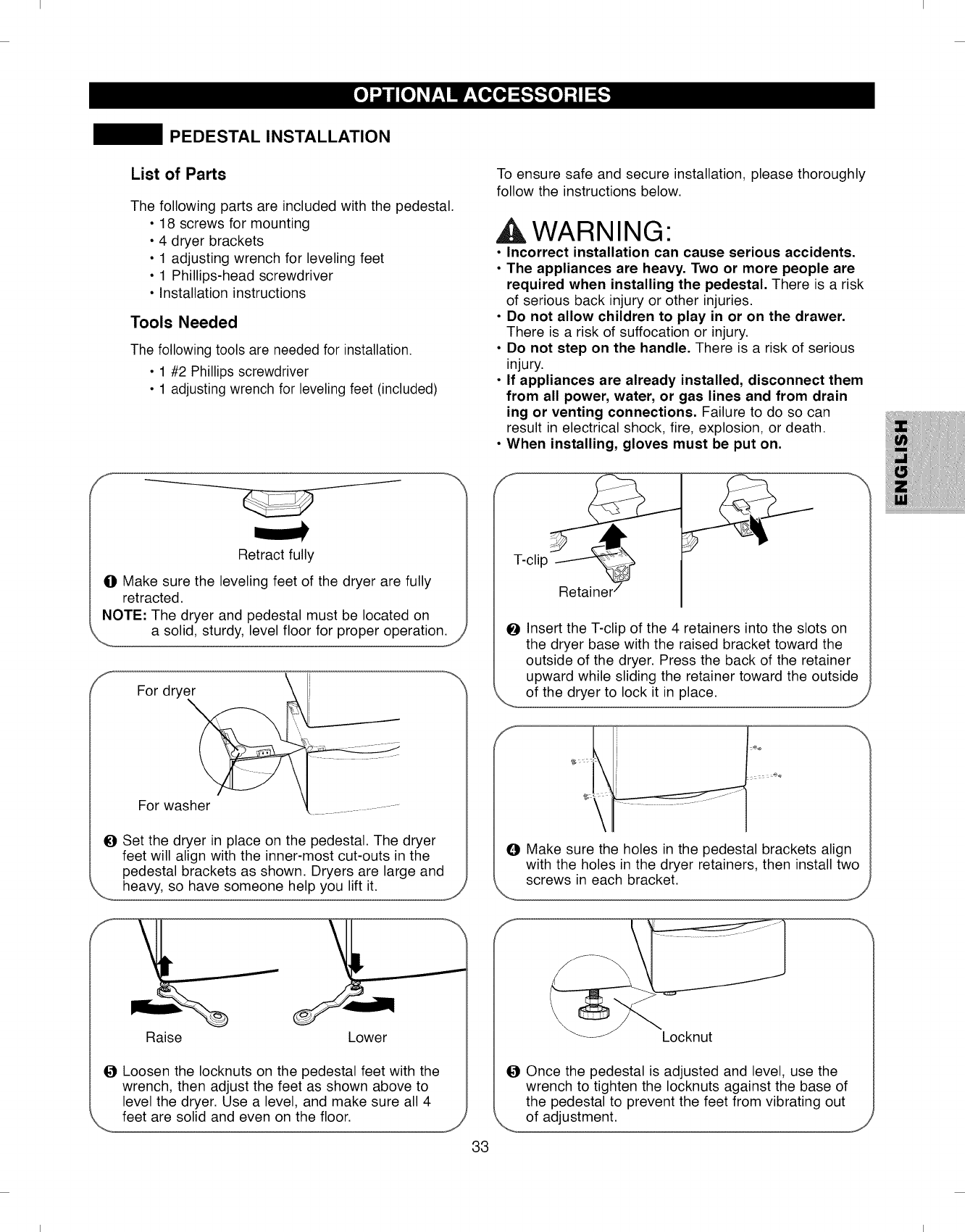
I I
PEDESTAL INSTALLATION
List of Parts
The following parts are included with the pedestal.
• 18 screws for mounting
• 4 dryer brackets
• 1 adjusting wrench for leveling feet
• 1 Phillips-head screwdriver
• Installation instructions
Tools Needed
The following tools are needed for installation.
• 1 #2 Phillips screwdriver
• 1 adjusting wrench for leveling feet (included)
Retract fully
OMake sure the leveling feet of the dryer are fully
retracted.
NOTE: The dryer and pedestal must be located on
a solid, sturdy, level floor for proper operation.
For drye_
",,,
For washer
OSet the dryer in place on the pedestal. The dryer
feet will align with the inner-most cut-outs in the
pedestal brackets as shown. Dryers are large and
heavy, so have someone help you lift it.
Raise Lower
J
OLoosen the Iocknuts on the pedestal feet with the
wrench, then adjust the feet as shown above to
level the dryer. Use a level, and make sure all 4
feet are solid and even on the floor.
33
To ensure safe and secure installation, please thoroughly
follow the instructions below.
WARNING"
•Incorrect installation can cause serious accidents.
•The appliances are heavy. Two or more people are
required when installing the pedestal. There is a risk
of serious back injury or other injuries.
•Do not allow children to play in or on the drawer.
There is a risk of suffocation or injury.
•Do not step on the handle. There is a risk of serious
injury.
• If appliances are already installed, disconnect them
from all power, water, or gas lines and from drain
ing or venting connections. Failure to do so can
result in electrical shock, fire, explosion, or death.
• When installing, gloves must be put on.
T-clip
OInsert the T-clip of the 4 retainers into the slots on
the dryer base with the raised bracket toward the
outside of the dryer. Press the back of the retainer
upward while sliding the retainer toward the outside
of the dryer to lock it in place.
OMake sure the holes in the pedestal brackets align
with the holes in the dryer retainers, then install two
screws in each bracket.
/
_Locknut
OOnce the pedestal is adjusted and level, use the
wrench to tighten the Iocknuts against the base of
the pedestal to prevent the feet from vibrating out
of adjustment.
\
I I
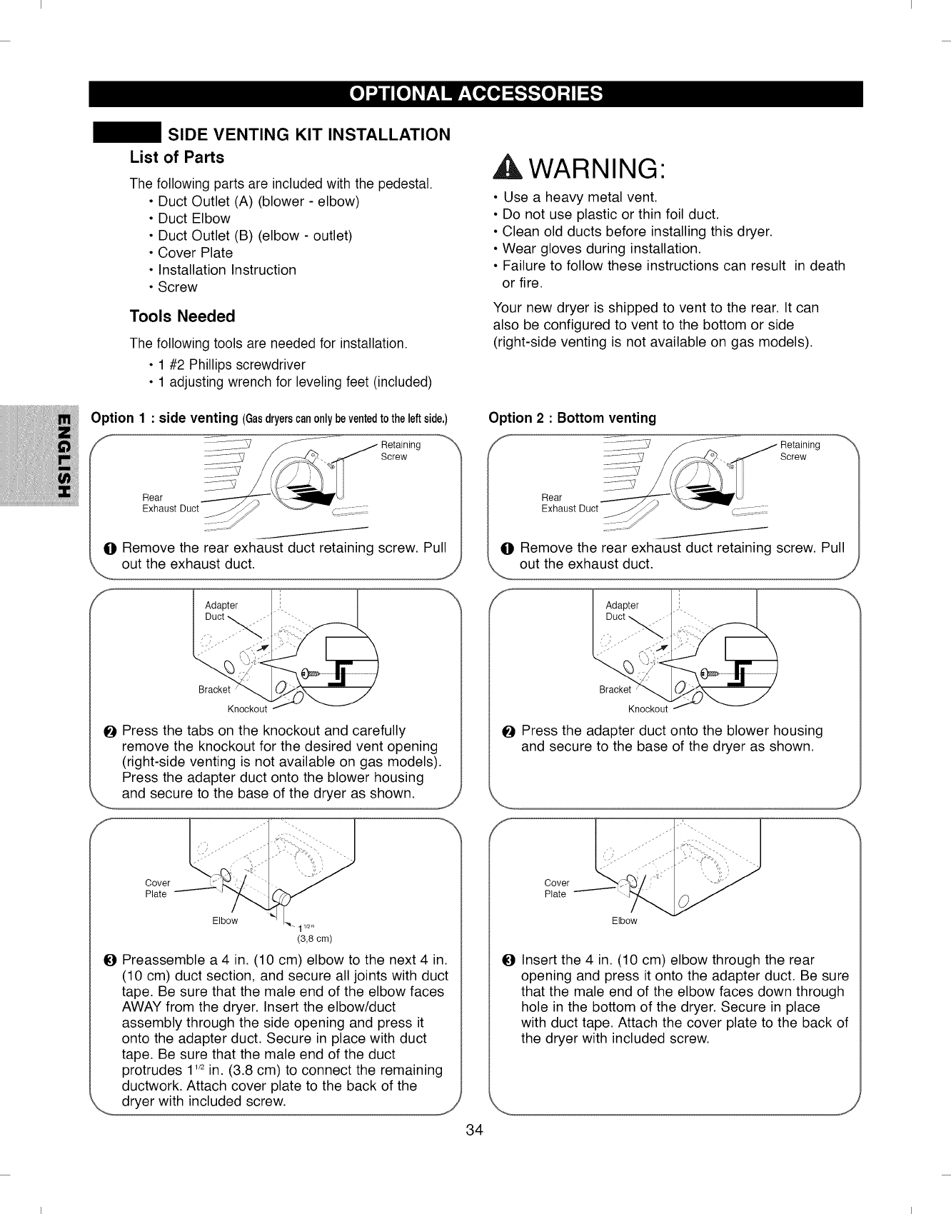
I I
SIDE VENTING KIT INSTALLATION
List of Parts
The following parts are included with the pedestal.
• Duct Outlet (A) (blower - elbow)
• Duct Elbow
• Duct Outlet (B) (elbow - outlet)
• Cover Plate
• Installation Instruction
• Screw
Tools Needed
The following tools are needed for installation.
• 1 #2 Phillips screwdriver
• 1 adjusting wrench for leveling feet (included)
Option 1: side venting (Gasdryerscanonlybeventedtotheleftside.)
f Retaining
_-_--_-_-_-2 Screw
]_LL-//]S
Rear
Exhaust Duct
O Remove the rear exhaust duct retaining screw. Pull
out the exhaust duct.
Bracket
Knockout
O Press the tabs on the knockout and carefully
remove the knockout for the desired vent opening
(right-side venting is not available on gas models).
Press the adapter duct onto the blower housing
and secure to the base of the dryer as shown.
Cover
Plate
Elbow
11/2fl
(3,8 cm)
O Preassemble a 4 in. (10 cm) elbow to the next 4 in.
(10 cm) duct section, and secure all joints with duct
tape. Be sure that the male end of the elbow faces
AWAY from the dryer. Insert the elbow/duct
assembly through the side opening and press it
onto the adapter duct. Secure in place with duct
tape. Be sure that the male end of the duct
protrudes 1'/2in. (3.8 cm) to connect the remaining
ductwork. Attach cover plate to the back of the
dryer with included screw, j_
34
,A WARNING"
• Use a heavy metal vent.
• Do not use plastic or thin foil duct.
• Clean old ducts before installing this dryer,
• Wear gloves during installation.
• Failure to follow these instructions can result in death
or fire,
Your new dryer is shipped to vent to the rear. It can
also be configured to vent to the bottom or side
(right-side venting is not available on gas models).
Screw
O Remove the rear exhaust duct retaining screw. Pull
out the exhaust duct.
i)......"
Bracket
Knockout
0 Press the adapter duct onto the blower housing
and secure to the base of the dryer as shown.
J
,J
Cover
Plate
Elbow
1_ Insert the 4 in. (10 cm) elbow through the rear
opening and press it onto the adapter duct. Be sure
that the male end of the elbow faces down through
hole in the bottom of the dryer. Secure in place
with duct tape. Attach the cover plate to the back of
the dryer with included screw.
I I
I I
One-Year Limited Warranty
When installed, operated and maintained according to all instructions supplied with the product, if this
appliance fails due to a defect in material and workmanship within one year from the date of purchase, call
1-800-4-MY-HOME _'_to arrange for free repair.
If this appliance is ever used for other than private family purposes, this warranty applies for only 90 days
from the date of purchase.
This warranty covers only defects in material and workmanship. Sears will NOT pay for:
0Expendable items that can wear out from normal use, including but not limited to filters, belts, light bulbs,
and bags.
O A service technician to instruct the user in correct product installation, operation or maintenance.
O A service technician to clean or maintain this product.
ODamage to or failure of this product if it is not installed, operated or maintained according to all the instruc-
tions supplied with the product.
0 Damage to or failure of this product resulting from accident, abuse, misuse or use for other than its intend-
ed purpose.
O Damage to or failure of this product caused by the use of detergents, cleaners, chemicals or utensils other
than those recommended in all instructions supplied with the product.
Damage to or failure of parts or systems resulting from unauthorized modifications made to this product.
Disclaimer of implied warranties; limitation of remedies
Customer's sole and exclusive remedy under this limited warranty shall be product repair as provided herein.
Implied warranties, including warranties of merchantability or fitness for a particular purpose, are limited to one
year or the shortest period allowed by law. Sears shall not be liable for incidental or consequential damages.
Some states and provinces do not allow the exclusion or limitation of incidental or consequential damages, or
limitation on the duration of implied warranties of merchantability or fitness, so these exclusions or limitations
may not apply to you.
This warranty applies only while this appliance is used in the United States or Canada.
This warranty gives you specific legal rights, and you may also have other rights which vary from state to state.
Sears, Roebuck and Co., Hoffman Estates, IL 60179
Sears Canada Inc., Toronto, Ontario, Canada M5B 2B8
35
I I
I I
INSTRUCCIONES IMPORTANTES DE SEGURIDAD
MENSAJES DE SEGURIDAD ..................... 39
INSTRUCCIONES IMPORTANTES DE SEGURIDAD...39-42
CARACTERJSTICAS Y VENTAJAS
Piezas y componentes significativos .................. 43
INSTRUCClONES DE INSTALAClON
Dimensiones y especificaciones significativas ............ 44
Requisitos de ubicaci6n .44
Escoger la ubicaci6n correcta . . ... . . i i. . .. . . ..44
Espacios libres ......................... 44
Instalaci6n con base de pedestal o kit
de apilado opcional ..................... 45
Accesorios opcionales ..................... 45
Requerimientos de gas .46
Conexi6n de tas secadoras de gas ............... 46,47
Requerimientos de etectricos ................... 48
Conexi6n de las secadoras de etectricas ........... 48,49
Ventilaci6n de la secadora ................ 50,51
Nivetaci6n de la secadora .................... 52
Cambio de sentido det giro de apertura de la puerta ..... 52
Comprobaci6n final de la instataci6n ................ 53
COMO USAR
Funciones det panel de control ................... 54
Funcionamiento de la secadora ................. 55
Guia de cictos .............................. 56
Clasificaci6n de cargas ........................... 57
Carga det la secadora ......................... 57
Pantalla de tiempo y estado ................. 58
Botones modificadores de ciclo ............... 59
ORcionesdel ciclo y funciones especiates ............. 60
INKLE GUARD (anti-arrugas) .................... 60
CONTROL LOCK (btoqueo de controles) ............ 60
SANITIZE CYCLE (desinfecci6n) .............. 60
RACK DRY CYCLE (secado con bandeja) ............ 60
Funciones de vapor .................... 61
Acerca det vapor .......................... 61
Utilizaci6n del ciclo STEAM REFRESH(refresco por vapor)...61
Utilizaci6n de la opci6n STATIC SHIELD (anti-estatica) ..... 61
Para rellenar et atimentador de vapor ................ 62
Notas importantes acerca de los ciclos de vapor ....... 62
INSTRUCCIONES DE MANTENIMIENTO PARA EL USARIO
Limpieza regular ...................... 63
Limpieza del exterior ....................... 63
Limpieza det interior ...................... 63
Limpieza atrededor y bajo la secadora .............. 63
Mantenimiento de los conductos ...................... 63
Limpieza det fittro de petusas ...................... 63
GUJA DE SOLUClON DE PROBLEMAS
Antes de soticitar asistencia tecnica ........... 64-67
ACCESORIOS OPClONALES
Instalaci6n del kit de apitado ..................... 68
Instalaci6n det pedestal ................... 68
Instataci6n det kit de ventilaci6n lateral ............ 70
GARANTJA ............................... 71
En el espacio que se muestra a continuaci6n, registre la
fecha de compra, el n° de modelo y el n° de sene de su
producto. PodrD.encontrar los n0meros de modelo y de
serie impresos en una p.laca de identificaci6n ubicada
dentro de la .puerta de la secadora. Tenga disponible
esta informaci6n siempre que entre en contacto con
Sears en relaci6n con su producto.
N° de modelo.
Fecha de compra
N° de serie.
Guarde estas instrucciones, y su ticket de compra, para
futuras consultas. 38
Contrato maestro de proteccibn
Felicidades por realizar una compra inte/igente. Su nuevo
producto Kenmore _"_'ha sido disefiado y fabricado para
proporcionarle afios de funcionamiento fiable. Pero, como
todos los productos, puede necesitar un mantenimiento
preventivo o reparaciones puntuales. Contarcon una
Acuerdomaestro de protecci6npuedeahorrarledineroy
problemas.
El Contrato maestro de protecci6n tambi6n ayuda a ampliar la
vida Qtilde su nuevo producto. Esto es Io que incluye el
Contrato*:
. Piezas y mano de obra necesarias para ayudar a
mantener el funcionamiento correcto de los productos
bajo un uso normal, no s61odefectos. Nuestra
cobertura va mb.s all_ de la garantia den producto. Sin
exclusi6n de fallos deducibles ni funcionales de la
cobertura-- proteccibn real.
. Servicio especializado con un ej6rcito de m_.sde 10
000 t6cnicos de servicio Sears autorizados, Io que
significa que su producto estar_, en manos de alguien
en quien puede confiar.
.Asistencia telef6nica y servicio de mantenimiento y
reparacibn a escala nacional, cada vez que nos
necesite, cuantas veces nos necesite.
. Garantfa pot piezas defectuosas---sustituci6n de su
producto cubierto por la garantia si experimenta cuatro
o mD.saverias en un plazo de doce meses.
. Sustitucibn del producto si su producto cubierto por la
garantia no puede repararse.
. Revisibn anual de mantenimiento preventivo a
peticibn--cin coste adicional.
. La ayuda r_pida por tei6fono la denominamos
Resoluci6n r_.pida.Asistencia telefOnica en todos los
productos pot parte de un representante de Sears.
Piense en nosotros como en un "manual del usuario
parlante".
. Proteccibn de sobrecarga contra dafios el6ctricos
debidos a fluctuaciones del suministro.
.Proteccibn de 2505 pot p6rdida de alimentos
anuales por cualquier p6rdida de alimentos debida a
fallos mecb.nicos de cualquier frigorifico o congelador
bajo garantia.
. Devolucibn den coste por alquiier si una reparaci6n
del producto cubierto por la garantia tardara m_.s
tiempo del previsto.
. 10% de descuento sobre el precio habitual de
cualquier servicio de reparaci6n no cubierto y de las
piezas instaladas asociadas.
Una vez adquirido el acuerdo una simple Ilamada
telef6nica es todo Io que hace falta para concertar su cita
de servicio. Puede Ilamar a cualquier hora del dia o la
noche, o fijar la hora de la reparaciOn online.
El Contrato maestro de protecci6n se traduce en una
compra libre de riesgos. Si, pot cualquier raz6n, realiza
una cancelaciOn durante el periodo de garantia del
producto, le proporcionaremos un reembolso completo o
prorrateado una vez expirado el periodo de garantfa del
producto, iAdquiera hoy mismo su Contrato maestro de
protecciOn!
Algunas limitaciones y exclusiones son aplicables.
Para obtener informaci6n sobre #recios y adicional en
los EE.UU., Ilame al 1=800=827=6655.
*La cobertura en Canad_ difiere en algunos aspectos.
Para obtener informacibn completa, pbngase en
contacto con Sears Canad_ Ilamando al
1=800=361=6665.
Servicio de instalacibn Sears
Para solicitar la instalaci6n profesional de Sears para la
instalaci6n dom6stica de electrodom6sticos, mecanismos
de apertura para puertas de garaje, calentadores de agua
y otros electrodom6sticos en]os EE.UU. o Canada Ilame
al 1-800-4-MY-HOME_fi
I I
I I
LSA TODAS LA |NSTRUCCiONSS ANTSS DE USAR
este manual para minimizar el riesgo de incendio oexplosibn, descarga electric& opara prevenir
da_os a la propiedad, lesiones personales o muerte.
Su Seguridad y la de los demas son de suma importancia.
En este manual yen su electrodomestico figuran muchos mensajes importantes de seguridad. Lea y cumpla siempre
con todos los mensajes de seguridad.
I_ste es el simbolo de alerta de seguridad.
El mismo alerta sobre potenciales riesgos de muerte o heridas tanto para usted como para otras personas.
Todos los mensajes de seguridad estar#.n a continuaci6n del simbolo de alerta de seguridad y con la palabra
PELIGRO o ADVERTENCIA. Estas palabras significan:
PIELiGRO: Corre riesgo de muerte o de sufrir heridas serias si no sigue las instrucciones inmediatamente.
,& ADVIERTIENCiA: Corre riesgo de muerte o de sufrir heridas serias si no sigue las instrucciones.
Todos los mensajes de seguridad le indicaran cu#.l es el riesgo potencial, le diran c6mo reducir las posibilidades de
sufrir heridas y que puede suceder si no se siguen las instrucciones.
No instale una secadora junto a materiales de ventilacibn pl_sticos fiexibles. Si se instala un
conducto flexible met_lico (de tipo I_mina de metal), este deber_ cumplir las especificaciones
determinadas pot el fabricante del electrodomestico para su uso con secadoras. Se sabe que los
materiales de ventilacibn flexibles se contraen, se agrietan con rapidez y atrapan pelusas. Estas
condiciones obstruir_n el flujo de aire de la secadora y aumentar_n el riesgo de incendio.
• No aimacene o use gasolina ni ning_n otto tipo de vapores o liquidos inflamables cerca de este
electrodomestico ni de ning_n otto electrodomestico.
• 0nicamente un tecnico calificado de mantenimiento, agencia de mantenimiento o compaSia de
gas deber_n realizar ei mantenimiento y la instalaci6n.
Instale la secadora seg_n las instrucciones del fabricante y las normativas locales.
•Guarde estas instrucciones.
QUE HACER S| HUELE GAS:
1. No intente encender un cigarrillo o fosforo, ni encender ningun electrodornestico a gas o electrico.
2. No toque ningun interruptor electrico. No use ningun telefono en su edificio.
3. No permita que ninguna persona se encuentre en la habitacion, edificio oarea.
4. Llame a su compaSia de gas inmediatamente desde el telefono de un vecino. Siga las instrucciones de su
cornpa_ia de gas al pie de la letra.
5. Si no puede cornunicarse con su cornpa_ia de gas, Ilame al departamento de bornberos.
39
I I
I I
Precauciones basicas de seguridad
ADVERTENCIA: porsu seguridad, se debe seguir la informacibn indicada en este manual para
minimizar el riesgo de incendio o explosibn, descarga electrica, o para prevenir dahos a la propiedad, lesiones
personales o muerte.
•Lea todas las instrucciones antes de usar la
secadora.
• Antes de usar, la secadora debe estar correctamente
instalada como se describe en este manual.
• No coloque artfculos que hayan sido expuestos a
aceites, incluyendo aceites comestibles, en su
secadora. Los artfculos contaminados con aceites
comestibles podrfan contribuir a la generaci6n de una
reacci6n qufmica que podrfa ocasionar que una carga
se incendie.
• No seque artfculos que hayan sido limpiados,
lavados, remojados o salpicados previamente con
gasolina, disolventes de limpieza en seco u otras
substancias inflamables o explosivas, ya que emanan
vapores que podrfan encenderse o explotar, incluso
despues del lavado.
• No introduzca las manos en la secadora cuando el
tambor o las otras partes esten en movimiento.
• No repare o reemplace ninguna parte de la secadora
ni intente reparar la misma a menos que esto se
recomiende en forma especffica en esta Gufa de Uso
y Cuidado o en instrucciones de reparaci6n
publicadas las cuales comprende y sabe aplicar.
• No altere los controles.
• Antes de porter la secadora fuera de servicio o de
tirarla, quite la puerta para prevenir que los ni_os se
metan dentro.
• No deje que los ni_os jueguen en la secadora ni
dentro de ella. Cuando se usa la secadora cerca de
los ni_os, se necesita una supervisi6n estricta.
• Use suavizadores de tela o productos para eliminar
est#.tica Qnicamente del modo recomendado por el
fabricante.
• No use calor para secar artfculos que contienen
caucho espumoso, pl#.sticos o materiales de textura
similar al caucho.
• Evite la acumulaci6n de pelusa, polvo o tierra
alrededor del #.rea de la apertura de ventilaci6n y
#.reas adyacentes.
• La parte interior de la secadora y el conducto de
ventilaci6n se deber_.n limpiar peri6dicamente, y la
misma deber#, ser realizada por personal calificado
del servicio.
• No instale ni coloque esta secadora en lugares donde
pueda estar expuesta a variables clim#.ticas.
• Antes de cargar la secadora, siempre revise que no
haya objetos extra_os en su interior.
• Retire la pelusa del filtro antes de cada carga.
Ley ejecutiva para la seguridad del agua potable y los
tbxicos de California (CaliforniaSafe DrinkingWater and Toxic EnforcementAct)
Esta ley requiere que el gobernador de California publique un listado de sustancias conocidas en el estado que causan
c#.ncer, defectos congenitos u otras lesiones reproductivas, y obliga a los negocios a alertar a los clientes sobre la posible
exposici6n a tales sustancias.
Los electrodomesticos a gas pueden causar exposici6n leve a cuatro de estas sustancias, principalmente benceno,
mon6xido de carbono, formaldehfdo y hollfn, generado principalmente por la combusti6n parcial del gas natural o los
combustibles LP (petr61eo Ifquido).
Las secadoras calibradas adecuadamente minimizar#.n la combusti6n parcial. Para minimizar incluso m#.s la
exposici6n a estas sustancias, se puede dotar a la secadora de la ventilaci6n adecuada al exterior.
INSTRUCCIONES DE CONEXION A TIERRA
Este electrodomestico deber#, estar conectado a tierra. En caso de averfa o mal funcionamiento, la conexi6n a tierra
reducir#, el riesgo de descargas electricas al brindar un camino con una resistencia menor para la corriente electrica. Este
electrodomestico debe estar equipado con un cable con un conductor para la conexi6n a tierra del equipo y un enchufe
con conexi6n a tierra. El enchufe deber_, estar conectado a una toma de corriente instalada en forma adecuada y con
conexi6n a tierra de acuerdo con todos los c6digos y ordenanzas locales.
AADVERTENCIA: Una conexibn inapropiada del conductor de conexibn a tierra del equipo puede
provocar riesgos de descargas electricas. Consulte a un electricista calificado o personal del servicio si tiene dudas de
que el electrodomestico se encuentre conectado a tierra apropiadamente.
No modifique el enchufe que se entrega con el electrodomestico. Si no coincide con la toma de corriente, contrate a un
electricista calificado para que instale una toma de corriente en forma adecuada.
Este electrodomestico debe estar conectado a un sistema de cableado de metal permanente con conexi6n a tierra o se
debe tender un conducto para la conexi6n a tierra del equipo con los conductores del circuito y conectado al terminal de
tierra del equipo o al conductor de suministro del electrodomestico.
Si la secadora no se encuentra adecuadamente conectada a tierra se pueden producir descargas electricas.
40
I I
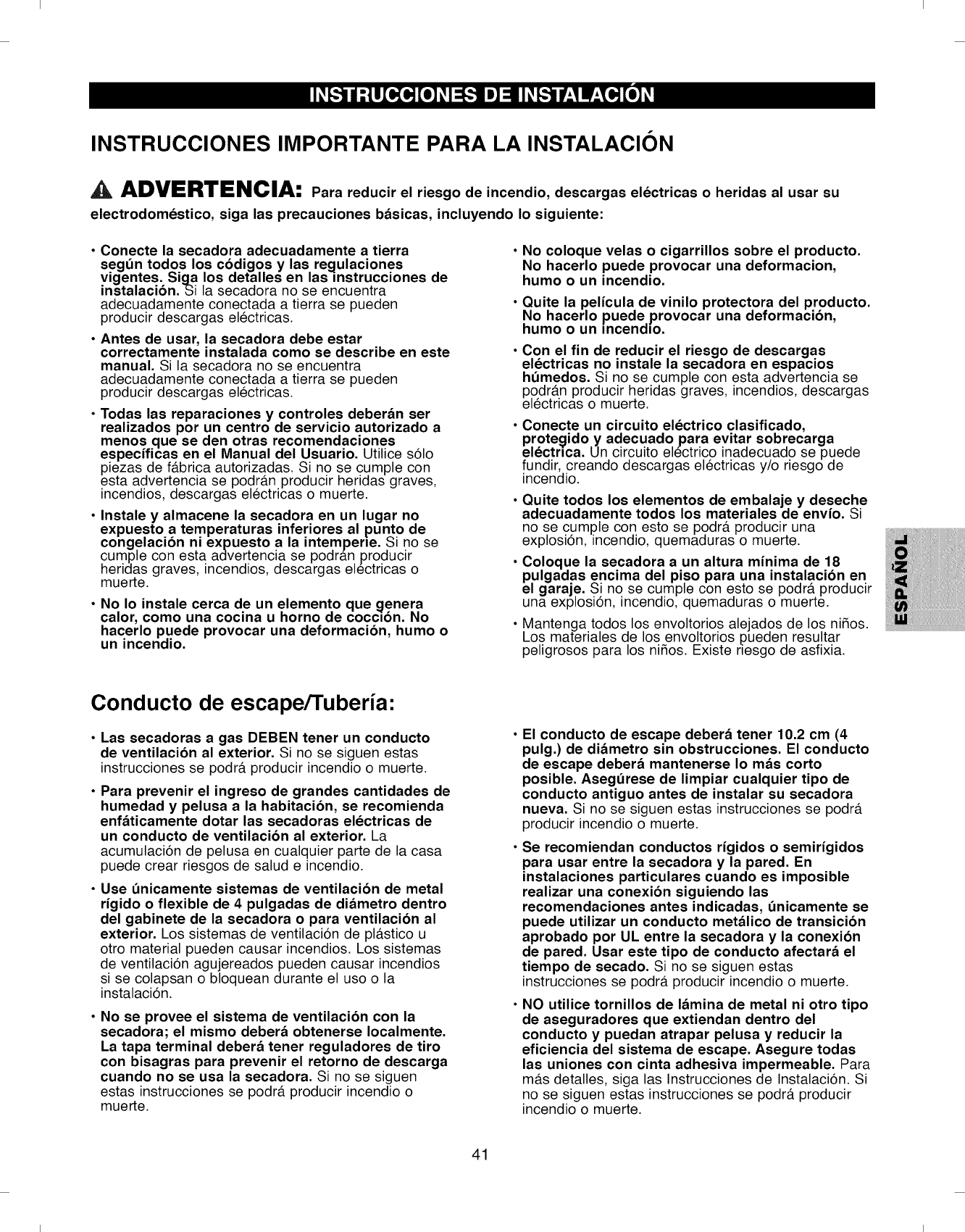
I I
INSTRUCCIONES IMPORTANTE PARA LA INSTALACION
ADVERTENClA: Para reducir el riesgo de incendio, descargas electricas o heridas al usar su
electrodomestico, siga las precauciones b&sicas, incluyendo Io siguiente:
Conecte la secadora adecuadamente a tierra
segBn todos los cbdigos y las regulaciones
vigentes. Siga los detalles en las instrucciones de
instalacibn.Si la secadora no se encuentra
adecuadamente conectada a tierra se pueden
producir descargas electricas.
Antes de usar, la secadora debe estar
correctamente instalada como se describe en este
manual. Si la secadora no se encuentra
adecuadamente conectada a tierra se pueden
producir descargas electricas.
Todas las reparaciones y controles deber&n ser
realizados por un centro de servicio autorizado a
menos que se den otras recomendaciones
especificas en el Manual del Usuario. Utilice s61o
piezas de f#.brica autorizadas. Si no se cumple con
esta advertencia se podr#.n producir heridas graves,
incendios, descargas electricas o muerte.
Instale y almacene la secadora en un lugar no
expuesto a temperaturas inferiores al punto de
congelacibn ni expuesto a la intemperie. Si no se
cumple con esta advertencia se podr_.n producir
heridas graves, incendios, descargas ele'ctricas o
muerte.
No Io instale cerca de un elemento que genera
calor, como una cocina u homo de coccion. No
hacerlo puede provocar una deformacibn, humo o
un incendio.
No coloque velas o cigarrillos sobre el producto.
No hacerlo puede provocar una deformacion,
humo o un incendio.
Quite la pelicula de vinilo protectora del producto.
No hacerlo puede provocar una deformacibn,
humo o un incendio.
Con el fin de reducir el riesgo de descargas
electricas no instale la secadora en espacios
hBmedos. Si no se cumple con esta advertencia se
podr#.n producir heridas graves, incendios, descargas
electricas o muerte.
Conecte un circuito electrico clasificado,
protegido y adecuado para evitar sobrecarga
electrica. Un circuito electrico inadecuado se puede
fundir, creando descargas electricas y/o riesgo de
incendio.
• Quite todos los elementos de embalaje y deseche
adecuadamente todos los materiales de envio. Si
no se cumple con esto se podr_, producir una
explosi6n, incendio, quemaduras o muerte.
• Coloque la secadora a un altura minima de 18
pulgadas encima del piso para una instalacibn en
el garaje. Si no se cumple con esto se podr#, producir
una explosi6n, incendio, quemaduras o muerte.
Mantenga todos los envoltorios alejados de los nifios.
Los materiales de los envoltorios pueden resultar
peligrosos para los nifios. Existe nesgo de asfixia.
Conducto de escape/Tuberia"
Las secadoras a gas DEBEN tener un conducto
de ventilacibn al exterior. Si no se siguen estas
instrucciones se podr#, producir incendio o muerte.
Para prevenir el ingreso de grandes cantidades de
humedad y pelusa a la habitacibn, se recomienda
enf&ticamente dotar las secadoras electricas de
un conducto de ventilacibn al exterior. La
acumulaci6n de pelusa en cualquier parte de la casa
puede crear riesgos de salud e incendio.
Use 0nicamente sistemas de ventilacibn de metal
rigido o flexible de 4 pulgadas de di&metro dentro
del gabinete de la secadora o para ventilacibn al
exterior. Los sistemas de ventilaci6n de pl#.stico u
otro material pueden causar incendios. Los sistemas
de ventilaci6n agujereados pueden causar incendios
si se colapsan o bloquean durante el uso o la
instalaci6n.
No se provee el sistema de ventilacibn con la
secadora; el mismo deber& obtenerse Iocalmente.
La tapa terminal deber& tener reguladores de tiro
con bisagras para prevenir el retorno de descarga
cuando no se usa la secadora. Si no se siguen
estas instrucciones se podr#, producir incendio o
muerte.
El conducto de escape deber& tener 10.2 cm (4
pulg.) de di&metro sin obstrucciones. El conducto
de escape deber& mantenerse Io m&s corto
posible. AsegBrese de limpiar cualquier tipo de
conducto antiguo antes de instalar su secadora
nueva. Si no se siguen estas instrucciones se podr#.
producir incendio o muerte.
Se recomiendan conductos rigidos o semirigidos
para usar entre la secadora y la pared. En
instalaciones particulares cuando es imposible
realizar una conexibn siguiendo las
recomendaciones antes indicadas, Onicamente se
puede utilizar un conducto met&lico de transicibn
aprobado pot UL entre la secadora y la conexibn
de pared. Usar este tipo de conducto afectar& el
tiempo de secado. Si no se siguen estas
instrucciones se podr#, producir incendio o muerte.
NO utilice tornillos de I&mina de metal ni otro tipo
de aseguradores que extiendan dentro del
conducto y puedan atrapar pelusa y reducir la
eficiencia del sistema de escape. Asegure todas
las uniones con cinta adhesiva impermeable. Para
m#.s detalles, siga las Instrucciones de Instalaci6n. Si
no se siguen estas instrucciones se podr#, producir
incendio o muerte.
41
I I
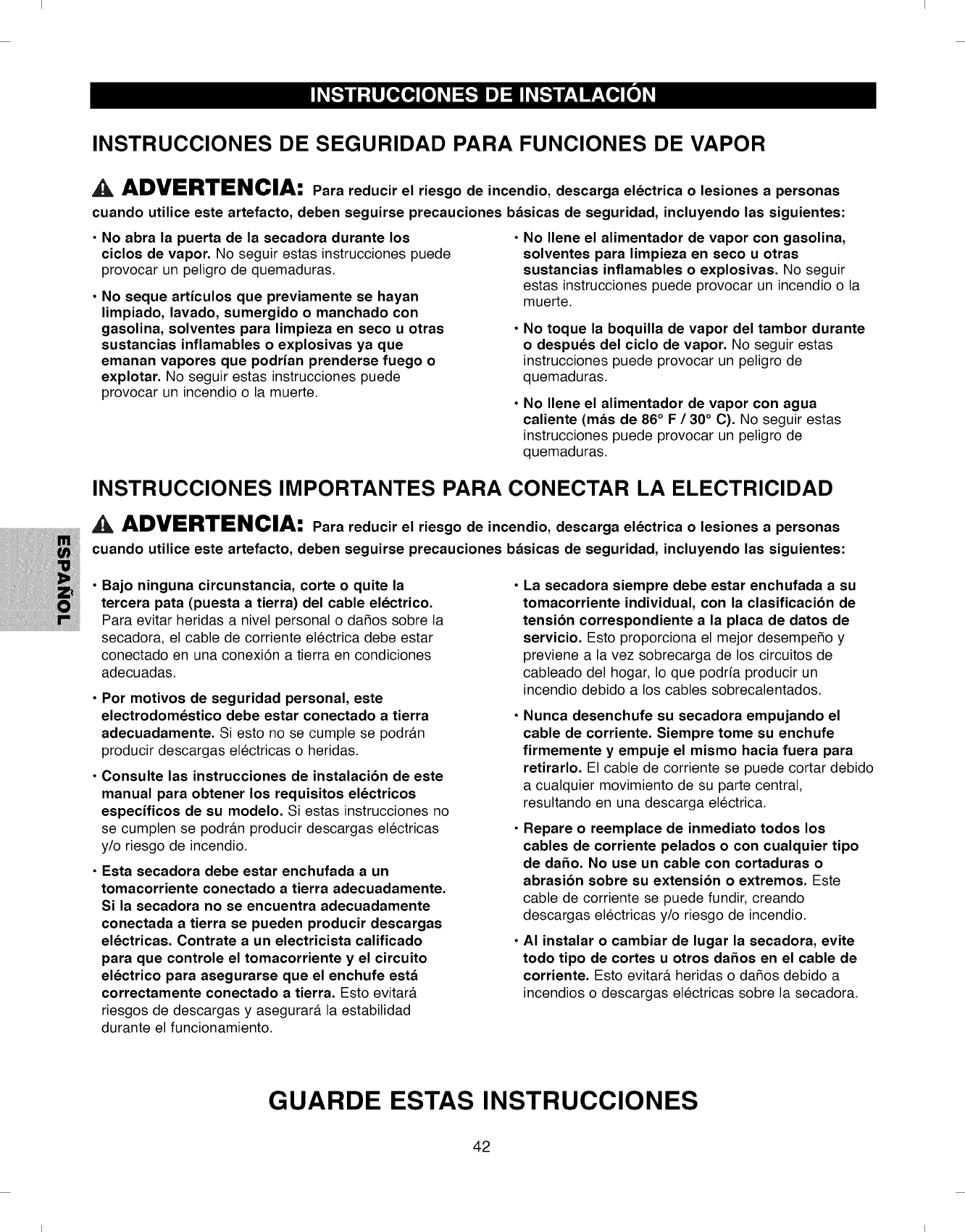
I I
INSTRUCCIONES DE SEGURIDAD PARA FUNCIONES DE VAPOR
ADVERTENClA: Para reducir el riesgo de incendio, descarga electrica o lesiones a personas
cuando utilice este artefacto, deben seguirse precauciones b&sicas de seguridad, incluyendo las siguientes:
• No abra la puerta de la secadora durante los
ciclos de vapor. No seguir estas instrucciones puede
provocar un peligro de quemaduras.
•No seque articulos que previamente se hayan
limpiado, lavado, sumergido o manchado con
gasolina, solventes para limpieza en seco u otras
sustancias inflamables o explosivas ya que
emanan vapores que podrian prenderse fuego o
explotar. No seguir estas instrucciones puede
provocar un incendio o la muerte.
No Ilene el alimentador de vapor con gasolina,
solventes para limpieza en seco u otras
sustancias inflamables o explosivas. No seguir
estas instrucciones puede provocar un incendio o la
muerte.
No toque la boquilla de vapor del tambor durante
o despues del ciclo de vapor. No seguir estas
instrucciones puede provocar un peligro de
quemaduras.
No Ilene el alimentador de vapor con agua
caliente (m&s de 86° F /30° C). No seguir estas
instrucciones puede provocar un peligro de
quemaduras.
INSTRUCCIONES IMPORTANTES PARA CONECTAR LA ELECTRICIDAD
AADVERTENClA: Para reducir el riesgo de incendio, descarga electrica o lesiones a personas
cuando utilice este artefacto, deben seguirse precauciones b&sicas de seguridad, incluyendo las siguientes:
•Bajo ninguna circunstancia, corte o quite la
tercera pata (puesta a tierra) del cable electrico.
Para evitar heridas a nivel personal o da_os sobre la
secadora, el cable de corriente electrica debe estar
conectado en una conexi6n a tierra en condiciones
adecuadas.
•Por motivos de seguridad personal, este
electrodomestico debe estar conectado a tierra
adecuadamente. Si esto no se cumple se podr#.n
producir descargas electricas o heridas.
•Consulte las instrucciones de instalacibn de este
manual para obtener los requisitos electricos
especificos de su modelo. Siestas instrucciones no
se cumplen se podr#.n producir descargas electricas
y/o riesgo de incendio.
•Esta secadora debe estar enchufada a un
tomacorriente conectado a tierra adecuadamente.
Si la secadora no se encuentra adecuadamente
conectada a tierra se pueden producir descargas
electricas. Contrate a un electricista calificado
para que controle el tomacorriente y el circuito
electrico para asegurarse que el enchufe est&
correctamente conectado a tierra. Esto evitara
riesgos de descargas y asegurar#, la estabilidad
durante el funcionamiento.
La secadora siempre debe estar enchufada a su
tomacorriente individual, con la clasificacibn de
tensibn correspondiente a la placa de datos de
servicio. Esto proporciona el mejor desempe_o y
previene a la vez sobrecarga de los circuitos de
cableado del hogar, Io que podrfa producir un
incendio debido a los cables sobrecalentados.
Nunca desenchufe su secadora empujando el
cable de corriente. Siempre tome su enchufe
firmemente y empuje el mismo hacia fuera para
retirarlo. El cable de corriente se puede cortar debido
a cualquier movimiento de su parte central,
resultando en una descarga electrica.
Repare o reemplace de inmediato todos los
cables de corriente pelados o con cualquier tipo
de daho. No use un cable con cortaduras o
abrasibn sobre su extensibn o extremos. Este
cable de corriente se puede fundir, creando
descargas electricas y/o riesgo de incendio.
AI instalar o cambiar de lugar la secadora, evite
todo tipo de cortes u otros dahos en el cable de
corriente. Esto evitar#, heridas o da_os debido a
incendios o descargas electricas sobre la secadora.
GUARDE ESTAS INSTRUCCIONES
42
I I
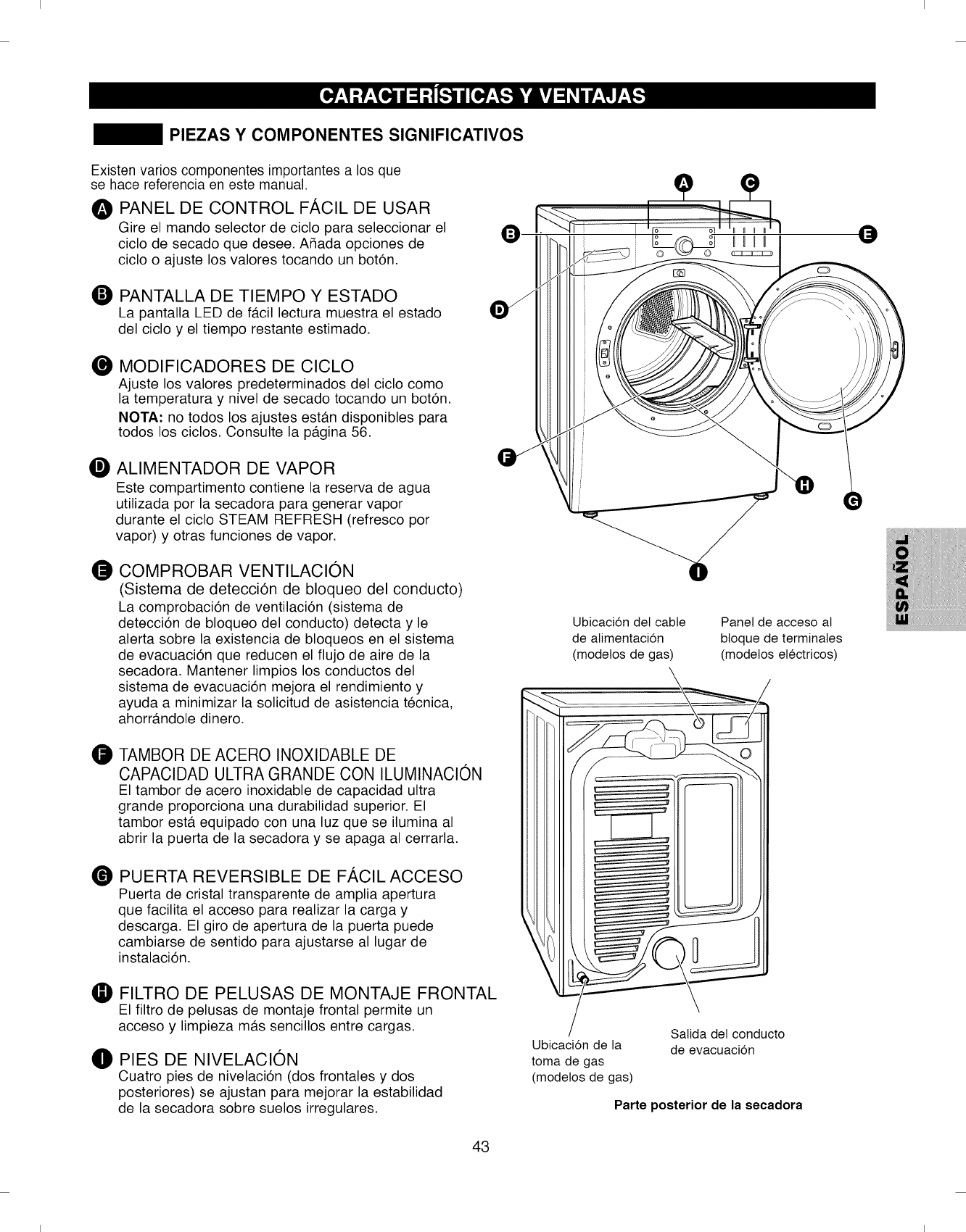
I I
PIEZAS Y COMPONENTES SIGNIFICATIVOS
Existen varies componentes importantes a los que
se hace referencia en este manual.
0PANEL DE CONTROL FACIL DE USAR
Gire el mando selector de ciclo para seleccionar el Q J.""'-_l"
)
ciclo de secado que desee. A_ada opciones de
ciclo o ajuste los valores tocando un bot6n.
O PANTALLA DE TIEMPO Y ESTADO
La pantalla LED de f#.cil lectura muestra el estado
del ciclo y el tiempo restante estimado.
MODIFICADORES DE CICLO
Ajuste los valores predeterminados del ciclo como
la temperatura y nivel de secado tocando un bot6n.
NOTA" no todos los ajustes est#.n disponibles para
todos los ciclos. Consulte la p#.gina 56.
OALIMENTADOR DE VAPOR
Este compartimento contiene la reserva de agua
utilizada por la secadora para generar vapor
durante el ciclo STEAM REFRESH (refresco por
vapor) y otras funciones de vapor.
COMPROBAR VENTILACION
(Sistema de detecciOn de bloqueo del conducto)
La comprobaci6n de ventilaci6n (sistema de
detecci6n de bloqueo del conducto) detecta y le
alerta sobre la existencia de bloqueos en el sistema
de evacuaci6n que reducen el flujo de aire de la
secadora. Mantener limpios los conductos del
sistema de evacuaci6n mejora el rendimiento y
ayuda a minimizar la solicitud de asistencia tecnica,
ahorr#.ndole dinero.
0TAMBOR DE ACERO INOXIDABLE DE
CAPACIDAD ULTRA GRANDE CON ILUMINACION
El tambor de acero inoxidable de capacidad ultra
grande proporciona una durabilidad superior. El
tambor est#. equipado con una luz que se ilumina al
abrir la puerta de la secadora y se apaga al cerrarla.
®PUERTA REVERSIBLE DE FACIL ACCESO
Puerta de cristal transparente de amplia apertura
que facilita el acceso para realizar la carga y
descarga. El giro de apertura de la puerta puede
cambiarse de sentido para ajustarse al lugar de
instalaci6n.
FILTRO DE PELUSAS DE MONTAJE FRONTAL
El filtro de pelusas de montaje frontal permite un
acceso y limpieza m#.s sencillos entre cargas.
OPIES DE NIVELACION
Cuatro pies de nivelaci6n (dos frontales y dos
posteriores) se ajustan para mejorar la estabilidad
de la secadora sobre suelos irregulares.
43
Ubicacion det cable
de alimentacion
(modetos de gas)
Panel de acceso at
btoque de terminales
(modetos electricos)
Ubicacion de la
toma de gas
(modetos de gas)
Satida det conducto
de evacuacion
Parte posterior de la secadora
I I
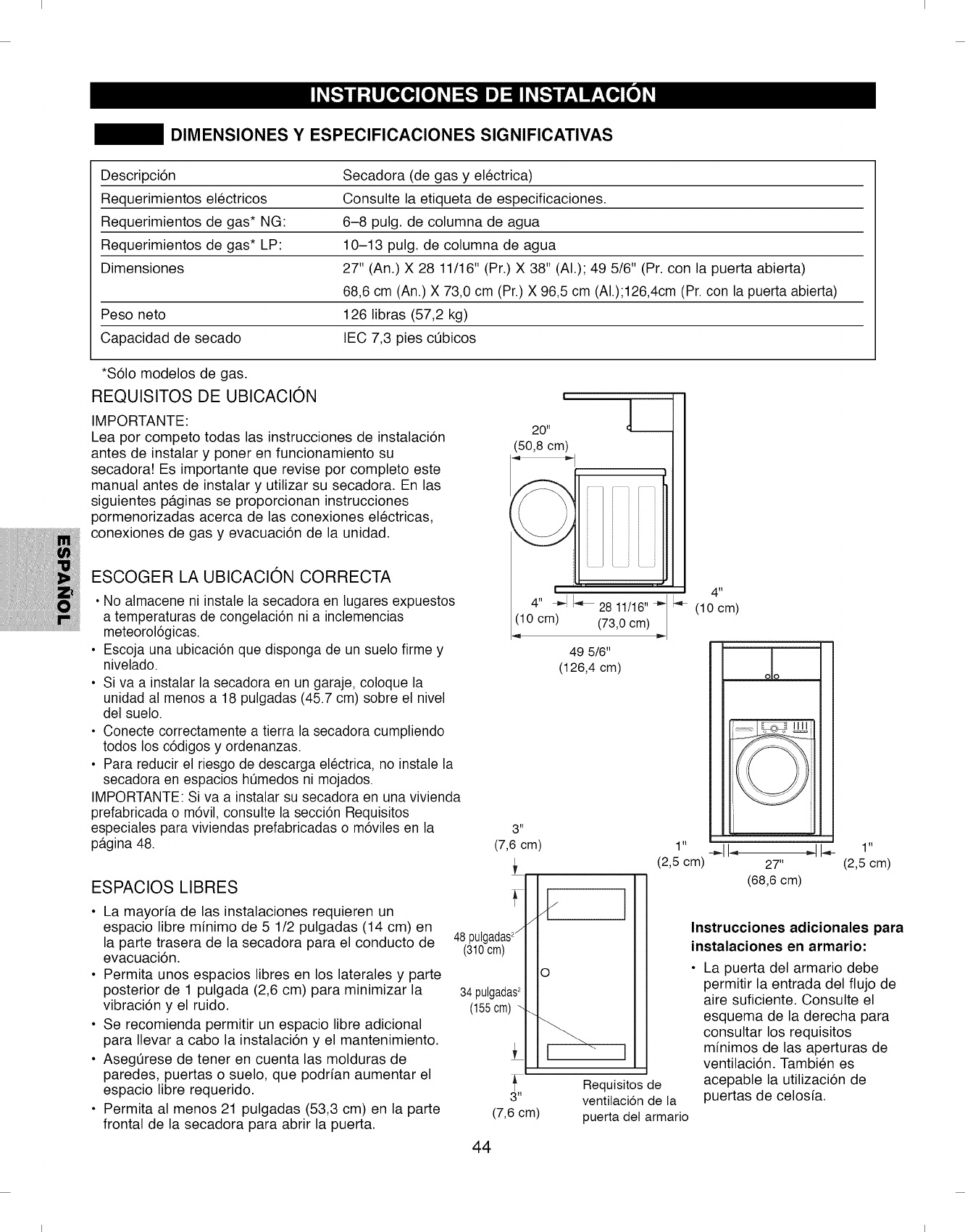
I I
DIMENSIONES Y ESPECIFICACIONES SIGNIFICATIVAS
Descripci6n Secadora (de gas y electrica)
Requerimientos electricos Consulte la etiqueta de especificaciones.
Requerimientos de gas* NG: 6-8 pulg. de columna de agua
Requerimientos de gas* LP: 10-13 pulg. de columna de agua
Dimensiones 27" (An.) X 28 11/16" (Pr.) X 38" (AI.); 49 5/6" (Pr. con la puerta abierta)
68,6 cm (An.) X 73,0 cm (Pr.) X 96,5 cm (AI.);126,4cm (Pr. con la puerta abierta)
Peso neto 126 libras (57,2 kg)
Capacidad de secado IEC 7,3 pies cQbicos
*$61o modelos de gas.
REQUISlTOS DE UBICACl0N
IMPORTANTE:
Lea por competo todas las instrucciones de instalaci6n
antes de instalar y porter en funcionamiento su
secadora! Es importante que revise por completo este
manual antes de instalar y utilizar su secadora. En las
siguientes p#.ginas se proporcionan instrucciones
pormenorizadas acerca de las conexiones electricas,
conexiones de gas y evacuaci6n de la unidad.
ESCOGER LA UBICACl0N CORRECTA
• No almacene ni instale la secadora en lugares expuestos
a temperaturas de congelaci6n ni a inclemencias
meteorol6gicas.
• Escoja una ubicaci6n que disponga de un suelo firme y
nivelado.
• Siva a instalar la secadora en un garaje, coloque la
unidad al menos a 18 pulgadas (45.7 cm) sobre el nivel
del suelo.
• Conecte correctamente a tierra la secadora cumpliendo
todos los c6digos y ordenanzas.
• Para reducir el riesgo de descarga electrica, no instale la
secadora en espacios ht_medos ni mojados.
IMPORTANTE: Siva a instalar su secadora en una vivienda
prefabricada o m6vil, consulte la secci6n Requisitos
especiales para viviendas prefabricadas o m6viles en la
pagina 48.
ESPAClOS LIBRES
3tl
(7,6 cm)
• La mayoria de las instalaciones requieren un
espacio libre minimo de 5 1/2 pulgadas (14 cm) en
la parte trasera de la secadora para el conducto de 48pulgadas2/
evacuaci6n. (310cm)
• Permita unos espacios libres en los laterales y parte
posterior de 1 pulgada (2,6 cm) para minimizar la 34pulgadas2
vibraci6n y el ruido. (155cm)-
• Se recomienda permitir un espacio libre adicional
para Ilevar a cabo la instalaci6n y el mantenimiento.
• AsegQrese de tener en cuenta las molduras de
paredes, puertas o suelo, que podrian aumentar el
espacio libre requerido.
• Permita al menos 21 pulgadas (53,3 cm) en la parte
frontal de la secadora para abrir la puerta.
o
l
Requisitos de
3" ventitacion de la
(7,6 cm) puerta det armario
Instrucciones adicionales para
instalaciones en armario:
La puerta del armario debe
permitir la entrada del flujo de
aire suficiente. Consulte el
esquema de la derecha para
consultar los requisitos
minimos de las aperturas de
ventilaci6n. Tambien es
acepable la utilizaci6n de
puertas de celosia.
44
I I
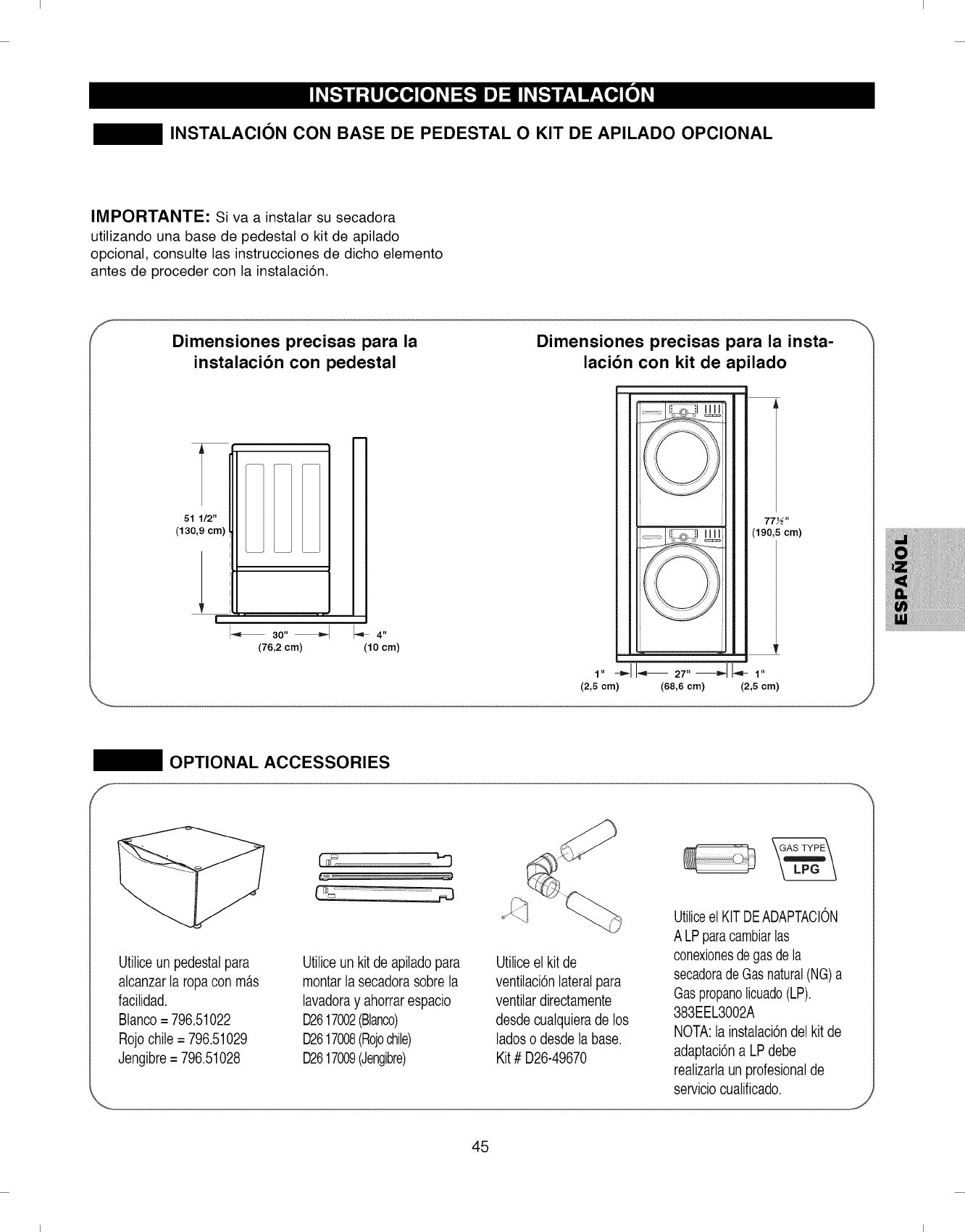
I I
INSTALACION CON BASE DE PEDESTAL O KIT DE APILADO OPCIONAL
IMPORTANTE: Siva a instalar su secadora
utilizando una base de pedestal o kit de apilado
opcional, consulte las instrucciones de dicho elemento
antes de proceder con la instalaci6n.
f_
Dimensiones precisas para la
instalacibn con pedestal
51 1/2"
(130,9 cm)
I_ 3o,,_ 1_4,,
(76,2 cm) (10 cm)
Dimensiones precisas para la insta-
lacibn con kit de apilado
i
1,,--_11-,_27,,_1-- 1,,
(2,5 cm) (68,6 cm) (2,5 cm)
OPTIONAL ACCESSORIES
F_
Utiticeun pedestalpara
alcanzar la ropacon m_.s
facitidad.
Btanco= 796.51022
Rojo chile = 796.51029
Jengibre = 796.51028
Utiliceun kit de apiladopara
montarla secadorasobre la
lavadoray ahorrarespacio
D2617002(Blanco)
D2617008(Rojochile)
D2617009(Jengibre)
Utilice et kit de
ventitaci6nlateral para
ventitardirectamente
desde cualquierade los
lades o desde la base.
Kit # D26-49670
Utiliceel KITDEADAPTACION
A LPparacambiarlas
conexionesdegas dela
secadorade Gasnatural(NG)a
Gaspropanelicuado(LP).
383EEL3002A
NOTA:la instaIaci6ndet kit de
adaptaci6na LPdebe
realizartaun profesionalde
servicio cualificado.
45
I I
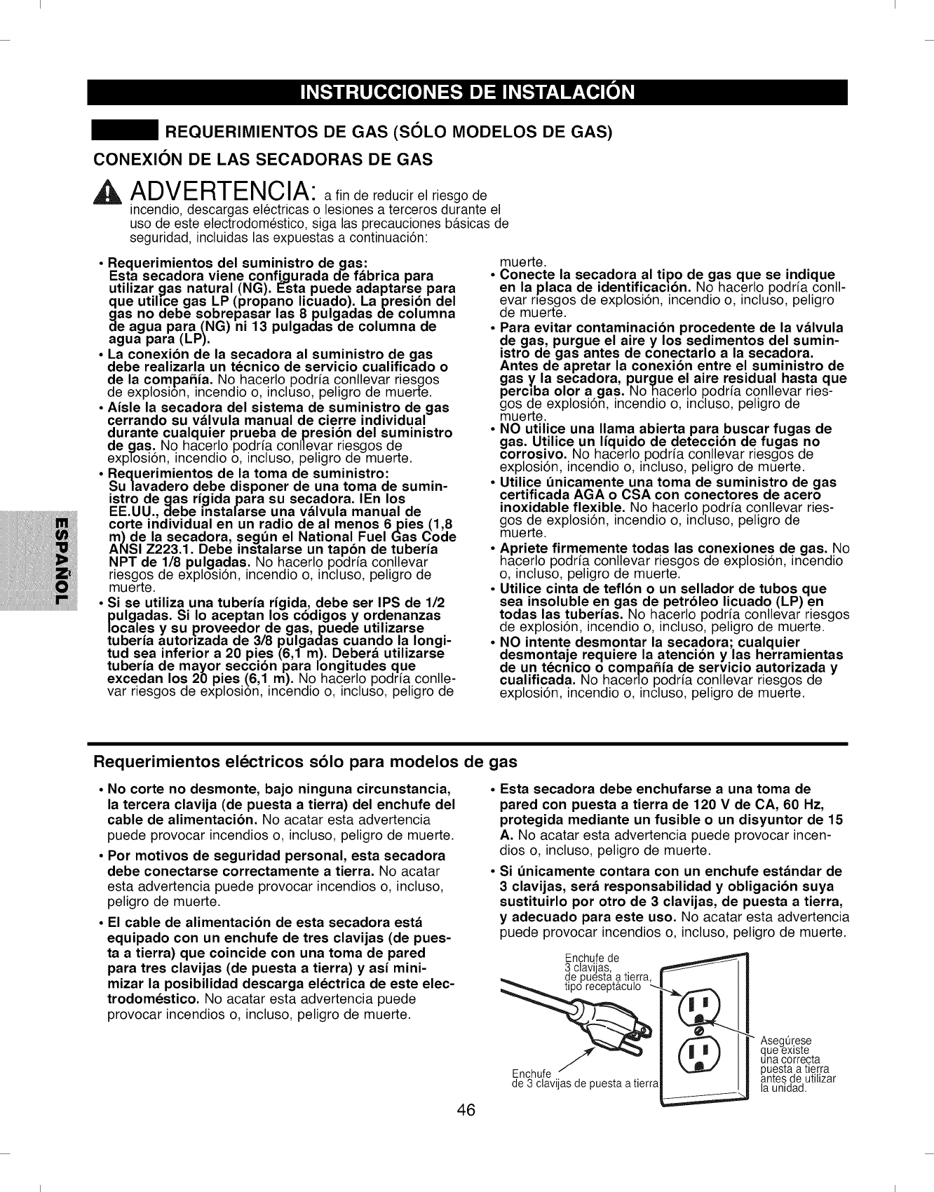
I I
REQUERIMIENTOS DE GAS (SOLO MODELOS DE GAS)
CONEXION DE LAS SECADORAS DE GAS
^ADVERTENCIA: afin de reducir el riesgo de
incendio, descargas electricas o lesiones a terceros durante el
use de este electrodomestico, siga las precauciones basicas de
seguridad, incluidas las expuestas a continuaci6n:
• Requerimientos del suministro de gas:
Esta secadora viene confi.gurada de f&brica para
utilizar gas natural (NG). Esta puede adaptarse para
que utihce gas LP (propano licuado). Lapresibn del
gas no debe sobrepasar las 8 pulgadas de columna
de agua para (NG) ni 13 pulgadas de columna de
agua para (LP).
° La conexibn de la secadora al suministro de gas
debe realizarla un tecnico de servicio cualificado o
de la compa_ia. No hacerlo podda conllevar riesgos
de explosio'n, incendio o, incluso, peligro de muerte.
• Aisle la secadora del sistema de surninistro de gas
cerrando su v_lvula manual de cierre individual
durante cualquier prueba de presi6n del surninistro
de gas. No hacerlo podria conllevar riesgos de
exp[osi6n, incendio o, incluso, peligro de muerte.
• Requerirnientos de la torna de surninistro:
Sulavadero debe disponer de una torna de surnin-
istro de gas rigida para su secadora. IEn los
EE.UU., debe instalarse una v_lvula manual de
corte individual en un radio de al rnenos 6pies (1,8
rn) de la secadora, seg_n el National Fuel Gas Code
ANSI Z223.1. Debe instalarse un tap6n de tuberia
NPT de 1/8 pulgadas. No hacerlo podria conllevar
riesgos de explosi6n, incendio o, incluso, peligro de
muerte.
• Si se utiliza una tuberia rigida, debe ser IPS de 1/2
pulgadas. Si Io aceptan los c6digos y ordenanzas
locales y su proveedor de gas,puede utilizarse
tuberia autorlzada de 3/8 pulgadas cuando la Iongi-
tud sea inferior a 20 pies (6,1 rn). Deber& utilizarse
tuberia de mayor secci6n para longitudes que
excedan los 20 pies (.6,1 rn). No hacerlo podria conlle-
var riesgos de explosion, incendio o, incluso, peligro de
muerte.
• Conecte la secadora al tipo de gas que se indique
en la placa de identificacl6n. No hacerlo podria conll-
evar nesgos de explosi6n, incendio o, incluso, peligro
de muerte.
°Para evitar contaminacibn procedente de la v_lvula
de gas, purgue el aire y los sedimentos del sumin-
istro de gas antes de conectarlo a la secadora.
Antes de apretar la conexibn entre el suministro de
gas y. la secadora, purgue el aire residual hasta que
perclba olor a gas. Nohacerlo podda conllevar ries-
gos de explosi6n, incendio o, incluso, peligro de
muerte.
•NO utilice una llama abierta para buscar fugas de
gas. Utilice un liquido de deteccibn de fugas no
corrosivo. No hacerlo podria conllevar riesgos de
explosi6n, incendio o, incluso, peligro de muerte.
°Utilice Onicamente una toma de suministro de gas
certificada AGA o CSA con conectores de acero
inoxidable flexible. No hacerlo podda conllevar ries-
gos de explosi6n, incendio o, incluso, peligro de
muerte.
• Apriete firrnernente todas las conexiones de gas. No
hacerlo podria conllevar riesgos de explosi6n, incendio
o, incluso, peligro de muerte.
• Utilice cinta de teflbn o un sellador de tubos que
sea insoluble en gas de petrbleo licuado (LP) en
todas las tuberias. No hacerlo podria conllevar riesgos
de explosi6n, incendio o, incluso, peligro de muerte.
• NO intente desrnontar la secadora; cualquier
desrnontaje requiere la atencibn ylas herrarnientas
de un tecnico o compahia de servicio autorizada y
cualificada. No hacerlo podria conllevar riesgos de
explosi6n, incendio o, incluso, peligro de muerte.
Requerimientos electricos solo para modelos de gas
°No corte no desmonte, bajo ninguna circunstancia,
la tercera clavija (de puesta a tierra) del enchufe del
cable de alimentacibn. No acatar esta advertencia
puede provocar incendios o, incluso, peligro de muerte.
• Por rnotivos de seguridad personal, esta secadora
debe conectarse correctarnente a tierra. No acatar
esta advertencia puede provocar incendios o, incluso,
peligro de muerte.
• El cable de alimentacibn de esta secadora est&
equipado con un enchufe de tres clavijas (de pues-
ta a tierra) que coincide con una toma de pared
para tres clavijas (de puesta a tierra) y asi mini-
mizar la posibilidad descarga electrica de este elec-
trodomestico. No acatar esta advertencia puede
provocar incendios o, incluso, peligro de muerte.
46
°Esta secadora debe enchufarse a una toma de
pared con puesta a tierra de 120 V de CA, 60 Hz,
protegida mediante un fusible o un disyuntor de 15
A. No acatar esta advertencia puede provocar incen-
dios o, incluso, peligro de muerte.
° Si Onicamente contara con un enchufe est&ndar de
3 clavijas, ser& responsabilidad y obligacibn suya
sustituirlo por otro de 3 clavijas, de puesta a tierra,
y adecuado para este uso. No acatar esta advertencia
puede provocar incendios o, incluso, peligro de muerte.
Enchufe de
3,clavija.s, ..
de puesta a t_erra,
Enchufe J
de 3 clavijas de puesta a tierra
_,==.=.===.==.=,.,,_
AsegQ(e.se
que ex_s_e
una correcta
puesta a tierra
antes de uti izar
la unidad.
I I
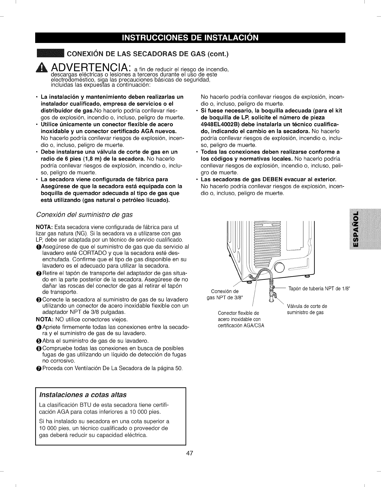
I I
CONEXION DE LAS SECADORAS DE GAS (cont.)
^ ADVERTENCIA: afin de reducir el riesgo de incendio,
descargas electricas o lesiones a terceros durante el uso de este
electrodomestico, siga las precauciones basicas de seguridad,
incluidas las expuestas a continuaci6n:
•La instalacibn y mantenimiento deben realizarlas un
instalador cualificado, empresa de servicios o el
distribuidor de gas.No hacerlo podria conllevar ries-
gos de explosi6n, incendio o, incluso, peligro de muerte.
• Utilice 0nicamente un conector flexible de acero
inoxidable yun conector certificado AGA nuevos.
No hacerlo podria conllevar riesgos de explosi6n, incen-
dio o, incluso, peligro de muerte.
•Debe instalarse una vblvula de corte de gas en un
radio de 6 pies (1,8 m) de la secadora. No hacerlo
podria conllevar riesgos de explosi6n, incendio o, inclu-
so, peligro de muerte.
•La secadora viene configurada de fbbrica para
Aseg0rese de que la secadora estb equipada con la
boquilla de quemador adecuada al tipo de gas que
estb utilizando (gas natural o petrbleo licuado).
No hacerlo podria conllevar riesgos de explosi6n, incen-
dio o, incluso, peligro de muerte.
• Si fuese necesario, la boquilla adecuada (para el kit
de boquilla de LP, solicite el nOmero de pieza
4948EL4002B) debe instalarla un tecnico cualifica-
do, indicando el cambio en la secadora. No hacerlo
podria conllevar riesgos de explosi6n, incendio o, inclu-
so, peligro de muerte.
• Todas las conexiones deben realizarse conforme a
los cbdigos ynormativas locales. No hacerlo podria
conllevar riesgos de explosi6n, incendio o, incluso, peli-
gro de muerte.
• Las secadoras de gas DEBEN evacuar al exterior.
No hacerlo podria conllevar riesgos de explosi6n, incen-
dio o, incluso, peligro de muerte.
Conexi6n del suministro de gas
NOTA: Esta secadora viene configurada de fabrica para ut
lizar gas natura (NG). Si la secadora va a utilizarse con gas
LP, debe ser adaptada per un tecnico de servicio cualificado.
OAsegerese de que el suministro de gas que da servicio al
lavadero este CORTADO y que la secadora este des-
enchufada. Confirme que el tipo de gas disponible en su
lavadero es el adecuado para utilizar la secadora.
Retire el tap6n de transporte del adaptador de gas situa-
do en la parte posterior de la secadora. Asegerese de no
dafiar las roscas del conector de gas al retirar el tap6n
de transporte.
OConecte la secadora al suministro de gas de su lavadero
utilizando un conector de acero inoxidable flexible con un
adaptador NPT de 3/8 pulgadas.
NOTA" NO utilice conectores viejos.
OApriete firmemente todas las conexiones entre la secado-
ra y el suministro de gas de su lavadero.
(}Abra el suministro de gas de su lavadero.
(_ Compruebe todas las conexiones en busca de posibles
fugas de gas utilizando un liquido de detecci6n de fugas
no corrosivo.
O Proceda con Ventilaci6n De La Secadora de la pagina 50.
Conexi6n de
gas NPT de 3/8"
Conector flexible de
acero inoxidable con
certificaci6n AGA/CSA
Tap6n de tuberia NPT de 1/8"
Wlvula de corte de
suministro de gas
Instalaciones a cotas altas
La clasificaci6n BTU de esta secadora tiene certifi-
caci6n AGA para cotas inferiores a 10 000 pies.
Si ha instalado su secadora en una cota superior a
10 000 pies, un tecnico cualificado o proveedor de
gas deber_, reducir su capacidad electrica.
47
I I
I I
REQUERIMIENTOS DE EL¢:CTRICOS
CONEXlON DE LAS SECADORAS DE ELI_CTRICAS
,A ADVERTENCIAPara ayudar a prevenir
incendios, descargas electricas, lesiones graves o
incluso la muerte, el cableado y la puesta a tierra
deben cumplir la edici6n mas reciente del National
Electrical Code, ANSI/NFPA 70 y todas las normativas
locales de aplicaci6n. P6ngase en contacto con un
electricista cualificado para comprobar el cableado y
los fusibles de su vivienda para asegurarse de que
dispone de la potencia electrica adecuada para utilizar
la secadora.
^, ADVERTENCIAafin de reducir el riesgo
de incendio, descargas electricas o lesiones a ter-
ceros durante el uso de este electrodomestico, siga
las precauciones b#.sicas de seguridad, incluidas
las expuestas a continuaci6n:
• Cualquier instalaci6n en una vivienda prefabricada o
m6vil debe cumplir con las directrices del Manufactured
Home Construction and Safety Standards, titulo 24
CFR, secci6n 32-80 6 con el est#.ndar CAN/CSAOZ240
MH y los c6digos y ordenanzas locales.
• Es precisa una conexi6n tetrafilar para las instala-
ciones realizadas en todas las viviendas m6viles y
prefabricadas, asi como toda nueva construcci6n a
partir del 1 de enero de 1996. No hacerlo podria con-
Ilevar riesgos de explosi6n, incendio o, incluso, peligro
de muerte.
48
^A_ ADVERTENCIAA fin de reducir el riesgo
de incendio, descargas electricas o lesiones a ter-
ceros durante el uso de este electrodomestico, siga
las precauciones b#.sicas de seguridad, incluidas
las expuestas a continuaci6n:
Esta secadora debe conectarse a un metal puesto a
tierra, un sistema de cableado permanente o los
conductores del circuito deben incluir un conduc-
tor de puesta a tierra del equipo que este conecta-
do al terminal de tierra del equipo o cable de la
secadora. No hacerlo podria conllevar riesgos de
explosi6n, incendio o, incluso, peligro de muerte.
La secadora dispone un bloque de terminales pro-
pio que debe conectarse a un circuito monof&sico
independiente de 240 V de CA y 60 Hz, con fusible
de 30 A. La secadora dispone un bloque de termi-
nales propio que debe conectarse a un circuito
monof&sico independiente de 240 V de CA y 60 Hz,
con fusible de 30 A (el circuito debe disponer de
fusibles en ambos extremos de la linea). EL SERVI-
CIO ELECTRICO PARA LA SECADORA DEBE SER
EL MAXIMO VOLTAJE NOMINAL INDICADO EN LA
PLACA DE ESPECIFICACIONES. NO CONECTE LA
SECADORA A UN CIRCUITO DE 110, 115 6120
VOLTIOS. Existen elementos de calefaccibn
disponibles para su instalacibn en secadoras que
deben conectarse a un suministro electrico de
voltaje diferente al especificado en su placa de
especificaciones. No acatar estas instrucciones puede
provocar incendios, explosiones o, incluso, peligro de
muerte.
° Si el ramal del circuito a la secadora tiene una Ion-
gitud igual o inferior a 15 pies (4,5 m), utilice el
cable AWG n° 10 con clasificacibn UL (Underwriters
Laboratories) (s61o cable de cobre) o el que
requieran los cbdigos locales. Si supera los 15 pies
(4,50 m), utilice el cable AWG n° 8 con clasificacibn
UL (s61o cable de cobre) o el que requieran los
Permita la suficiente holgura en el cableado para
que la secadora pueda ser desplazada de su ubi-
cacibn habitual cuando sea necesario. No hacerlo
podria conllevar riesgos de explosi6n, incendio o, inclu-
so, peligro de muerte.
•La conexibn del cable de alimentacibn (cable flexi-
ble de conexibn) entre la toma de pared y el bloque
de terminales de la secadora NO VIENE INCLUIDO
con la unidad. El tipo de cable flexible de conexibn
y su calibre deben cumplir los cbdigos locales y las
instrucciones que se proporcionan en las p&ginas
siguientes. No acatar estas instrucciones puede
provocar incendios, explosiones o, incluso, peligro de
muerte.
Es necesario disponer de una conexibn de tetrafilar
en toda nueva construccibn a partir del 1 de enero
de 1996. Debe utilizarse una conexibn de tetrafilar
alli donde los cbdigos locales no permitan la pues-
ta a tierra a traves del cable neutro. No hacerlo
podria conllevar riesgos de explosi6n, incendio o, inclu-
so, peligro de muerte.
I I
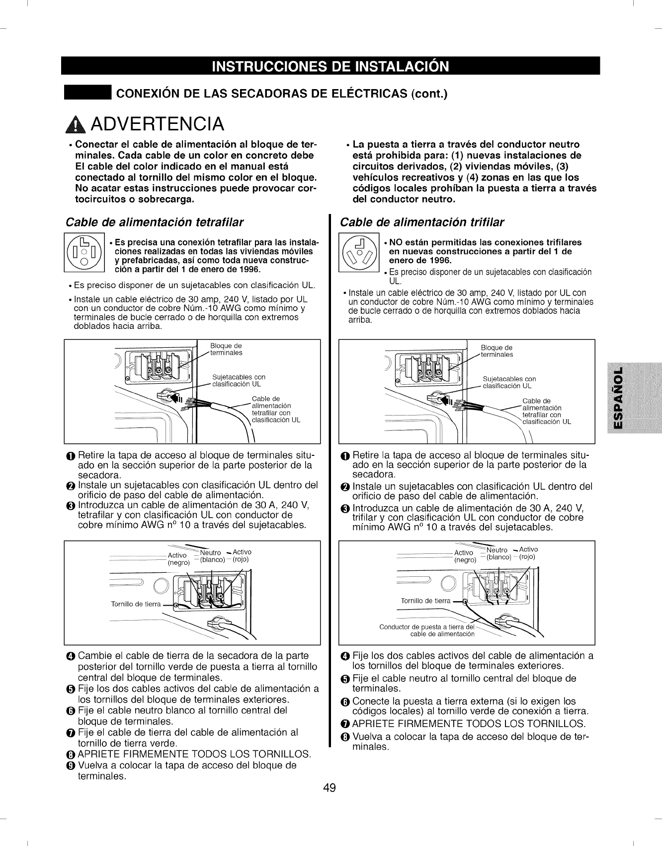
I I
CONEXION DE LAS SECADORAS DE ELI_CTRICAS (cont.)
,A ADVERTENCIA
, Conectar el cable de alimentaci6n al bloque de ter-
minales. Cada cable de un color en concreto debe
El cable del color indicado en el manual est_
conectado al tornillo del mismo color en el bloque.
No acatar estas instrucciones puede provocar cor-
tocircuitos o sobrecarga.
Cable de alimentacion tetrafilar
©•Es precisa una conexibn tetrafilar para las instala-
ciones realizadas en todas las viviendas moviles
y prefabricadas, asi como toda nueva construc-
cibn a partir del 1 de enero de 1996.
• Es preciso disponer de un sujetacabtes con clasificacion UL
• Instale un cable etectrico de 30 amp, 240 V, listado por UL
con un conductor de cobre NOm.-10 AWG como minimo y
terminales de bucle cerrado o de horquitla con extremos
dobtados hacia arriba.
Bloque de
Sujetacables con
UL
Cable de
tetrafilar con
clasificacion UL
@Retire la tapa de acceso al bloque de terminales situ-
ado en la secci6n superior de la parte posterior de la
secadora.
OInstale un sujetacables con clasificaci6n UL dentro del
orificio de paso del cable de alimentaci6n.
OIntroduzca un cable de alimentaci6n de 30 A, 240 V,
tetrafilar y con clasificaci6n UL con conductor de
cobre minimo AWG n° 10 a traves del sujetacables.
Activo Neutro _ Activo
:: ............................. (negro) (blanco) (rojo)
Tornillo de tierra
OCambie el cable de tierra de la secadora de la parte
posterior del tornillo verde de puesta a tierra al tornillo
central del bloque de terminales.
OFije los dos cables activos del cable de alimentaci6n a
los tornillos del bloque de terminales exteriores.
OFije el cable neutro blanco al tornillo central del
bloque de terminales.
OFije el cable de tierra del cable de alimentaci6n al
tornillo de tierra verde.
OAPRIETE FIRMEMENTE TODOS LOS TORNILLOS.
OVuelva a colocar la tapa de acceso del bloque de
terminales. 49
oLa puesta a tierra a traves del conductor neutro
est& prohibida para: (1) nuevas instalaciones de
circuitos derivados, (2) viviendas mbviles, (3)
vehiculos recreativos y (4) zonas en las que los
cbdigos locales prohiban la puesta a tierra a traves
del conductor neutro.
Cable de alimentacion trifilar
_/_ . NO est_m permitidas las conexiones trifilares
en nuevas construcciones a partir del 1 de
enero de 1996.
• Es preciso disponer de un sujetacables con clasificacion
UL.
• Instale un cable electrico de 30 amp, 240 V, listado por UL con
un conductor de cobre NQm.-10 AWG como minimo y terminales
de bucle cerrado o de horquilla con extremos doblados hacia
arriba.
Bloque de
@Retire la tapa de acceso al bloque de terminales situ-
ado en la secci6n superior de la parte posterior de la
secadora.
OInstale un sujetacables con clasificaci6n UL dentro del
orificio de paso del cable de alimentaci6n.
OIntroduzca un cable de alimentaci6n de 30 A, 240 V,
trifilar y con clasificaci6n UL con conductor de cobre
minimo AWG n° 10 a traves del sujetacables.
Activo _Neutro _Activo
............................... (negro) (blanco) (rojo)
cablede alimentaci0n _._ _\
Conducttordepuestaa t__..............................
OFije los dos cables activos del cable de alimentaci6n a
los tornillos del bloque de terminales exteriores.
OFije el cable neutro al tornillo central del bloque de
terminales.
OConecte la puesta a tierra extema (si Io exigen los
c6digos locales) al tornillo verde de conexi6n a tierra.
OAPRIETE FIRMEMENTE TODOS LOS TORNILLOS.
O Vuelva a colocar la tapa de acceso del bloque de ter-
minales.
I I
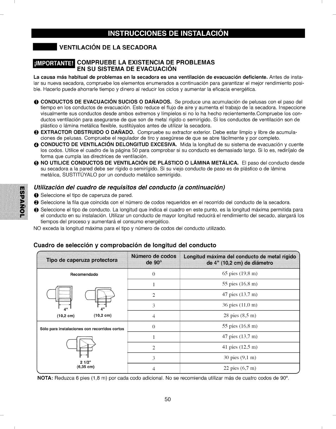
I I
VENTILACION DE LA SECADORA
COMPRUEBE LA EXISTENCIA DE PROBLEMAS
EN SU SISTEMA DE EVACUACION
La causa mds habitual de problemas en la secadora es una ventilacibn de evacuacibn deficiente. Antes de insta-
lar su nueva secadora, compruebe los elementos enumerados a continuaci6n para garantizar el mejor rendimiento posi-
ble. Hacerlo puede ahorrarle tiempo y dinero al reducir los ciclos y aumentar la eficacia energetica.
O CONDUCTOS DE EVACUACION SUCIOS O DANADOS. Se produce una acumulaci6n de pelusas con el paso del
tiempo en los conductos de evacuaci6n. Esto reduce el flujo de aire y aumenta el trabajo de la secadora. Inspeccione
visualmente sus conductos desde ambos extremos y limpielos si no Io ha hecho recientemente.Compruebe los con-
ductos ventilacidn para asegurarse de que son de metal rigido o semirigido. Si los conductos de ventilacidn son de
plfistico o Ifimina metfilica flexible, sustit0yalos antes de utilizar la secadora.
O EXTRACTOR OBSTRUlDO O DANADO. Compruebe su extractor exterior. Debe estar limpio y libre de acumula-
ciones de pelusas. Compruebe el regulador de tiro y aseg0rese de que se abre fficilmente y por completo.
O CONDUCTO DE VENTILAClON DELONGITUD EXCESlVA. Mida la Iongitud de su sistema de evacuaci6n y cuente
los codos. Utilice el cuadro de la pfigina 50 para comprobar si su conducto es demasiado largo. Si Io es, redirijalo de
forma que cumpla las directrices de ventilaci6n.
ONO UTILICE CONDUCTOS DE VENTILACION DE PLASTICO O LAMINA METALICA. El paso del conducto desde
su secadora a la pared debe ser rigido o semirigido. Si su viejo conducto de paso es de plfistico o de Ifimina
metfilica, SUSTITOYALO por un conducto metfilico semirigido.
Utilizacion del cuadro de requisitos del conducto (a continuacion)
Ill Seleccione el tipo de caperuza de pared.
O Seleccione la ilia que coincida con el n0mero de codos requeridos en el recorrido del conducto de la secadora.
O Seleccione el tipo de conducto. La Iongitud que indica el cuadro en este punto, es la Iongitud mfixima permitida para
el conducto en su instalaci6n. Utilizar un conducto de mayor Iongitud reducirfi el rendimiento del secado, alargarfi los
tiempos del proceso y aumentarfi el consumo energetico.
NO exceda la Iongitud mfixima para el tipo y n0mero de codos del conducto utilizado.
Cuadro de seleccibn y comprobacibn de Iongitud del conducto
Recomendado 0 65 pies (19,8 m)
4" 4"
(10,2 cm) (10,2 cm)
Solo para instalaciones con recorridos cortos
2 1/2"
(6,35 cm)
1
2
3
4
0
1
2
3
4
55 pies (16,8 m)
47 pies (13,7 m)
36 pies (11,0 m)
28 pies (8,5 m)
55 pies (16,8 m)
47 pies (13,7 m)
41 pies (12,5 m)
30 pies (9,1 m)
22 pies (6,7 m)
NOTA: Reduzca 6 pies (1,8 m) por cada codo adicional. No se recomienda utilizar mils de cuatro codos de 90°.
50
I I
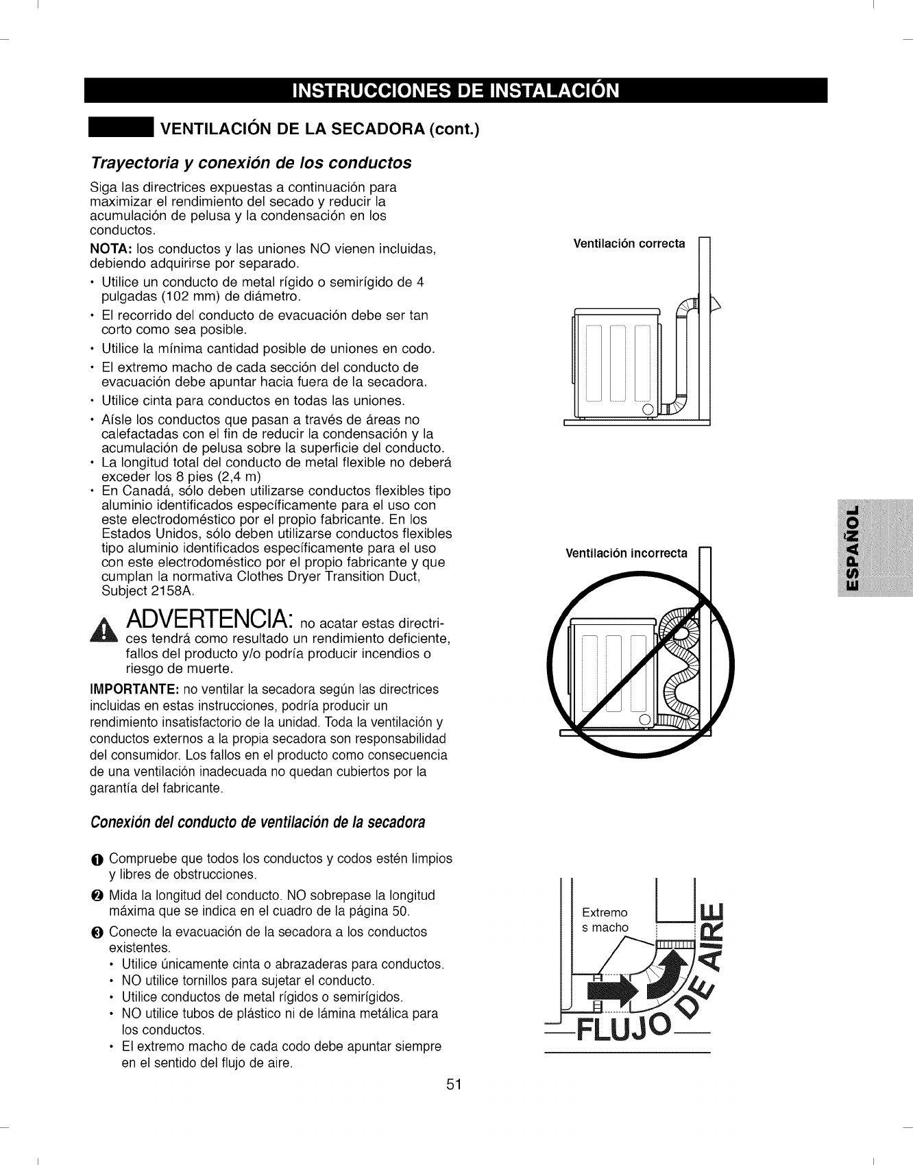
I I
VENTILACION DE LA SECADORA (cont.)
Trayectoria y conexion de los conductos
Siga las directrices expuestas a continuaci6n para
maximizar el rendimiento del secado y reducir la
acumulaci6n de pelusa y la condensaci6n en los
conductos.
NOTA: los conductos y las uniones NO vienen incluidas,
debiendo adquirirse por separado.
• Utilice un conducto de metal rigido o semirigido de 4
pulgadas (102 mm) de di#.metro.
• El recorrido del conducto de evacuaci6n debe ser tan
corto como sea posible.
• Utilice la minima cantidad posible de uniones en codo.
• El extremo macho de cada secci6n del conducto de
evacuaci6n debe apuntar hacia fuera de la secadora.
• Utilice cinta para conductos en todas las uniones.
• Aisle los conductos que pasan a traves de #.reas no
calefactadas con el fin de reducir la condensaci6n y la
acumulaci6n de pelusa sobre la superficie del conducto.
• La Iongitud total del conducto de metal flexible no deber#.
exceder los 8 pies (2,4 m)
• En Canad& s61o deben utilizarse conductos flexibles tipo
aluminio identificados especificamente para el uso con
este electrodomestico por el propio fabricante. En los
Estados Unidos, s61o deben utilizarse conductos flexibles
tipo aluminio identificados especificamente para el uso
con este electrodomestico por el propio fabricante y que
cumplan la normativa Clothes Dryer Transition Duct,
Subject 2158A.
ADVERTENCIA:no acatar estas directri-
ces tendrb, como resultado un rendimiento deficiente,
fallos del producto y/o podria producir incendios o
riesgo de muerte.
IMPORTANTE: no ventilar la secadora segt_nlas directrices
incluidas en estas instrucciones, podrfa producir un
rendimiento insatisfactorio de la unidad. Toda la ventilaci6n y
conductos externos a la propia secadora son responsabilidad
del consumidor. Los fallos en el producto como consecuencia
de una ventilaci6n inadecuada no quedan cubiertos por la
garantfa del fabricante.
Conexion del conductode venti/acionde/a secadora
(
Ventilacibn correcta
I ..... 1
Ventilacibn incorrecta
/' 1
@Compruebe que todos los conductos y codos esten limpios
y libres de obstrucciones.
_ Mida la Iongitud eel conducto. NO sobrepase la Iongitud [ l
maxima que se indica en el cuadro de la pagina 50. Extremo _,_
O Conecte la evacuaci6n de la secadora a los conductos s macho i_ I
existentes.
• Utilice _nicamente cinta o abrazaderas para conductos.
• NO utilice tornillos para sujetar el conducto.
• Utilice conductos de metal rfgidos o semirfgidos.
• NO utilice tubos de plastico ni de lamina metalica para
los conductos.
• El extremo macho de cada codo debe apuntar siempre
en el sentido del flujo de aire.
51
--FLUJq
I I
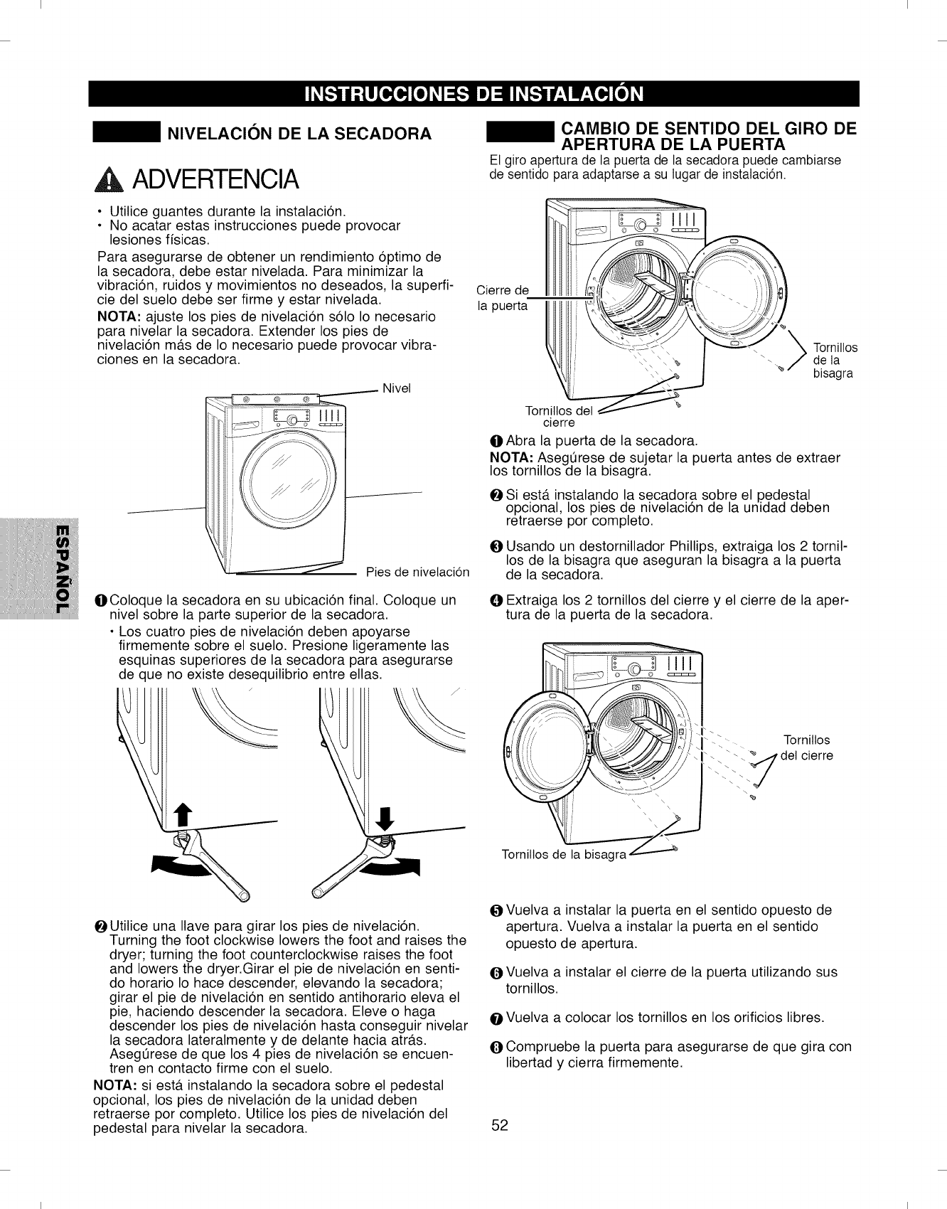
I I
NIVELACION DE LA SECADORA
,& ADVERTENCIA
•Utilice guantes durante la instalaci6n.
• No acatar estas instrucciones puede provocar
lesiones ffsicas.
Para asegurarse de obtener un rendimiento 6ptimo de
la secadora, debe estar nivelada. Para minimizar la
vibraci6n, ruidos y movimientos no deseados, la superfi-
cie del suelo debe ser firme y estar nivelada.
NOTA" ajuste los pies de nivelaci6n s61o Io necesario
para nivelar la secadora. Extender los pies de
nivelaci6n m#.s de Io necesario puede provocar vibra-
ciones en la secadora.
Nivel
Pies de nivelaci6n
OColoque la secadora en su ubicaci6n final. Coloque un
nivel sobre la parte superior de la secadora.
• Los cuatro pies de nivelaci6n deben apoyarse
firmemente sobre el suelo. Presione ligeramente las
esquinas superiores de la secadora para asegurarse
de que no existe desequilibrio entre elias.
CAMBIO DE SENTIDO DEL GIRO DE
APERTURA DE LA PUERTA
El giro apertura de la puerta de la secadora puede cambiarse
de sentido para adaptarse a su lugar de instalaci6n.
Cierre de _' -` _ ;)I_l
lapuerta III
cierre
0 Abra la puerta de la secadora.
NOTA" AsegQrese de sujetar la puerta antes de extraer
los tornillos de la bisagra.
Tornillos
de la
bisagra
Si est#. instalando la secadora sobre el pedestal
opcional, los pies de nivelaci6n de la unidad deben
retraerse por completo.
O Usando un destornillador Phillips, extraiga los 2 tornil-
los de la bisagra que aseguran la bisagra a la puerta
de la secadora.
O Extraiga los 2 tornillos del cierre y el cierre de la aper-
tura de la puerta de la secadora.
Torniltos de la bisagra
I""-- Torniltos
_ . -.._del cierre
d
ea
_Utilice una Ilave para girar los pies de nivelaci6n.
Turning the foot clockwise lowers the foot and raises the
dryer; turning the foot counterclockwise raises the foot
and lowers the dryer.Girar el pie de nivelaci6n en senti- (_
do horario Io hace descender, elevando la secadora;
girar el pie de nivelaci6n en sentido antihorario eleva el
pie, haciendo descender la secadora. Eleve o haga
descender los pies de nivelaci6n hasta conseguir nivelar O
la secadora lateralmente y de delante hacia atr#.s. Q
AsegQrese de que los 4 pies de nivelaci6n se encuen-
tren en contacto firme con el suelo.
NOTA" si est#. instalando la secadora sobre el pedestal
opcional, los pies de nivelaci6n de la unidad deben
retraerse por completo. Utilice los pies de nivelaci6n del
pedestal para nivelar la secadora. 52
Vuelva a instalar la puerta en el sentido opuesto de
apertura. Vuelva a instalar la puerta en el sentido
opuesto de apertura.
Vuelva a instalar el cierre de la puerta utilizando sus
tornillos.
Vuelva a colocar los tornillos en los orificios libres.
Compruebe la puerta para asegurarse de que gira con
libertad y cierra firmemente.
I I
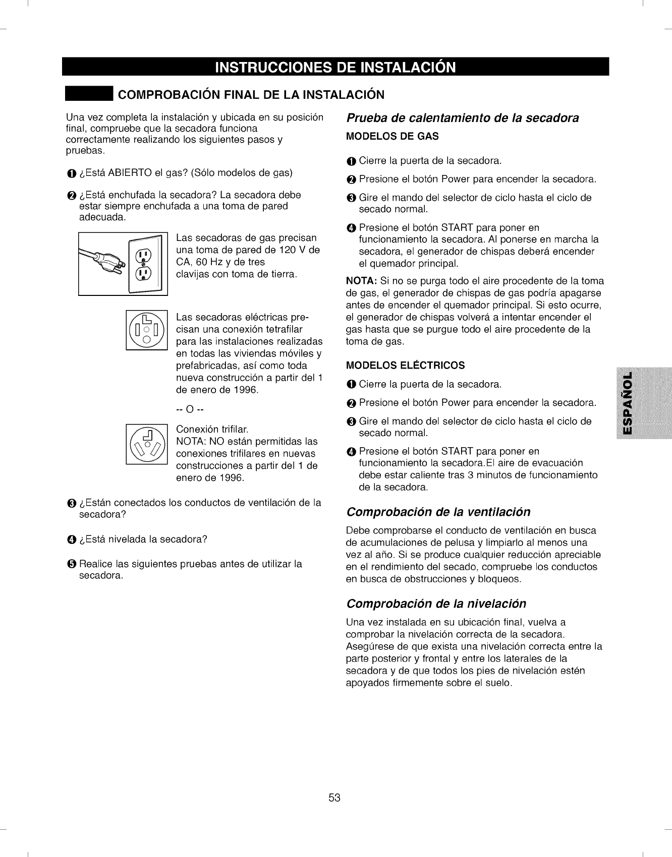
I I
COMPROBACION FINAL DE LA INSTALACION
Una vez completa la instalaci6n y ubicada en su posici6n
final, compruebe que la secadora funciona
correctamente realizando los siguientes pasos y
pruebas.
li]l z,Est#. ABIERTO el gas? ($61o modelos de gas)
Oz,Est#. enchufada la secadora? La secadora debe
estar siempre enchufada a una toma de pared
adecuada.
Las secadoras de gas precisan
una toma de pared de 120 V de
CA, 60 Hz y de tres
clavijas con toma de tierra.
@
©
Las secadoras electricas pre-
cisan una conexi6n tetrafilar
para las instalaciones realizadas
en todas las viviendas m6viles y
prefabricadas, asi como toda
nueva construcci6n a partir del 1
de enero de 1996.
-- O--
Conexi6n trifilar.
NOTA: NO est#.n permitidas las
conexiones trifilares en nuevas
construcciones a partir del 1 de
enero de 1996.
O&Est_.n conectados los conductos de ventilaci6n de la
secadora?
O&Est,. nivelada la secadora?
ORealice las siguientes pruebas antes de utilizar la
secadora.
Prueba de calentamiento de la secadora
MODELOS DE GAS
li]l Cierre la puerta de la secadora.
OPresione el bot6n Power para encender la secadora.
OGire el mando del selector de ciclo hasta el ciclo de
secado normal.
@Presione el bot6n START para poner en
funcionamiento la secadora. AI ponerse en marcha la
secadora, el generador de chispas deber#, encender
el quemador principal.
NOTA: Si no se purga todo el aire procedente de la toma
de gas, el generador de chispas de gas podria apagarse
antes de encender el quemador principal. Si esto ocurre,
el generador de chispas volver#, a intentar encender el
gas hasta que se purgue todo el aire procedente de la
toma de gas.
MODELOS ELI=CTRICOS
li]l Cierre la puerta de la secadora.
OPresione el bot6n Power para encender la secadora.
OGire el mando del selector de ciclo hasta el ciclo de
secado normal.
@Presione el bot6n START para poner en
funcionamiento la secadora.EI aire de evacuaci6n
debe estar caliente tras 3 minutos de funcionamiento
de la secadora.
Comprobacion de la ventilacion
Debe comprobarse el conducto de ventilaci6n en busca
de acumulaciones de pelusa y limpiarlo al menos una
vez al a_o. Si se produce cualquier reducci6n apreciable
en el rendimiento del secado, compruebe los conductos
en busca de obstrucciones y bloqueos.
Comprobacion de la nivelacion
Una vez instalada en su ubicaci6n final, vuelva a
comprobar la nivelaci6n correcta de la secadora.
AsegQrese de que exista una nivelaci6n correcta entre la
parte posterior y frontal y entre los laterales de la
secadora y de que todos los pies de nivelaci6n esten
apoyados firmemente sobre el suelo.
53
I I
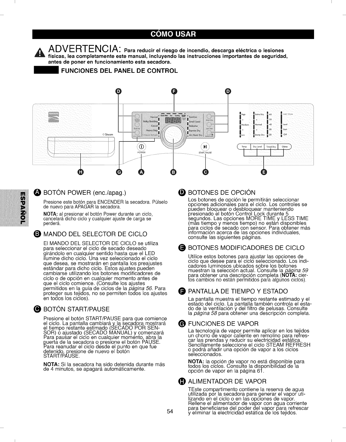
I I
ADV ERT ENC lA: Parareducirelriesgo de incendio, descarga electrica o lesiones
fisicas, lea completamente este manual, incluyendo las instrucciones importantes de seguridad,
antes de poner en funcionamiento esta secadora.
FUNCIONES DEL PANEL DE CONTROL
i i i ii / i
OBOTON POWER (enc./apag.)
Presione este bot6n para ENCENDER la secadora. PQlseto
de nuevo para APAGAR la secadora.
NOTA: al presionar el bot6n Power durante un cicto,
cancetar_,dicho cicto y cualquier ajuste de carga se
perder&
OMANDO DEL SELECTOR DE CICLO
El MANDO DEL SELECTOR DE CICLO se utiliza
para seleccionar el ciclo de secado deseado
gir4mdolo en cualquier sentido hasta que el LED
ilumine dicho ciclo. Una vez seleccionado el ciclo
que desea, se mostrargm en pantalla los preajustes
estgmdar para dicho ciclo. Estos ajustes pueden
cambiarse utilizando los botones modificadores de
ciclo o de opci6n en cualquier momento antes de
que el ciclo comience. (Consulte los ajustes
permitidos en la guia de ciclos de la pagina 56. Para
proteger sus tejidos, no se permiten todos los ajustes
en todos los ciclos).
O BOTON START/PAUSE
Presione el bot6n START/PAUSE para que comience
el ciclo. La pantalla cambiar4ty la secadora mostrar4t
el tiempo restante estimado (SECADO POR SEN-
SOR) o ajustado (SECADO MANUAL) y comenzar4t
Para pausar el ciclo en cualquier momento, abra la
_uerta de la secadora o preslone el bot6n PAUSE.
ara reanudar el ciclo desde el punto en que fue
detenido,presione de nuevo el bot6n
START/PAUSE.
NOTA: Si la secadora ha sido detenida durante mgts
de 4 minutos, se apagar4t automgtticamente.
54
®
O
O
@
@
BOTONES DE OPCION
Los botones de opci6n le permitir#.n seleccionar
opciones adicionales para el ciclo. Los controles se
pueden bloquear o desbloquear manteniendo
presionado el bot6n Control Lock durante 5
segundos. Las opciones MORE TIME y LESS TIME
(mas tiempo y menos tiempo) no est#.n disponibles
para ciclos de secado con sensor. Para obtener m#.s
informaci6n acerca de las opciones individuales,
consulte las siguientes p#.glnas.
BOTONES MODIFICADORES DE CICLO
Utilice estos botones para ajustar las opciones de
ciclo que desee para el ciclo seleccionado. Los indi-
cadores luminosos ubicados sobre los botones
muestran la selecci6n actual. Consulte la pagina 59
para obtener una descripci6n completa (NOTA: cier-
tos cambios no estan permitidos para algunos ciclos).
PANTALLA DE TIEMPO Y ESTADO
La pantalla muestra el tiempo restante estimado y el
estado del ciclo. La pantalla tambien controla el esta-
do de la ventilaci6n y del filtro de pelusas. Consulte
la pagina 58 para obtener una descripci6n completa.
FUNCIONES DE VAPOR
La tecnologia de vapor permite aplicar en los tejidos
un chorro de vapor caliente en remolino para refres-
car las prendas y reducir su electricidad estgttica.
Sencillamente seleccione el ciclo STEAM REFRESH
o podr#, a_adir una opci6n de vapor a los ciclos
seleccionados.
NOTA: la opci6n de vapor no est#. disponible para
todos los ciclos. Consulte la disponibihdad de la
opci6n de vapor en la p#.gina 61.
ALIMENTADOR DE VAPOR
TEste compartimento contiene la reserva de agua
utilizada por la secadora para generar el vapor uti-
lizando en el ciclo o en las opctones de vapor.
Rellene el alimentador de vapor con agua corriente
para beneficiarse del poder del vapor para refrescar
y eliminar la electricidad estgttica de los tejidos.
I I
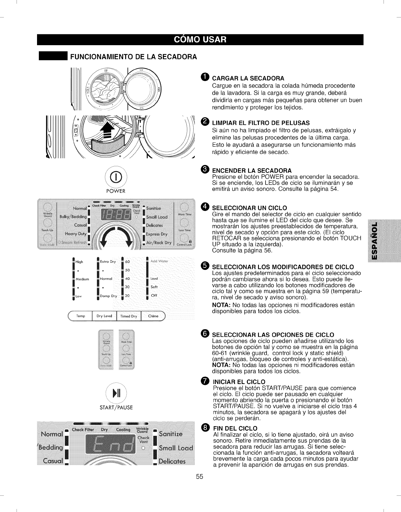
I I
FUNCIONAMIENTO DE LA SECADORA
POWER
High
i Extra Dr °° i .............
50 ILOUO
,0.
O CARGARLASECADORA
Cargue en la secadora la colada hOmeda procedente
de la lavadora. Si la carga es muy grande, deber#.
dividirla en cargas m#.s peque_as para obtener un buen
rendimiento y proteger los tejidos.
OLIMPIAR EL FILTRO DE PELUSAS
Si aOn no ha limpiado el filtro de pelusas, extr#.igalo y
elimine las pelusas procedentes de la 01tima carga.
Esto le ayudar#, a asegurarse un funcionamiento m#.s
r#.pido y eficiente de secado.
OENCENDER LA SECADORA
Presione el bot6n POWER para encender la secadora.
Si se enciende, los LEDs de ciclo se iluminar#.n y se
emitir#, un aviso sonoro. Consulte la p#.gina 54.
O SELECCIONAR UN CICLO
Gire el mando del selector de ciclo en cualquier sentido
hasta que se ilumine el LED del ciclo que desee. Se
mostrar#.n los ajustes preestablecidos de temperatura,
nivel de secado y opci6n para este ciclo. (El ciclo
RETOCAR se selecciona presionando el bot6n TOUCH
UP situado a la izquierda).
Consulte la p#.gina 56.
OSELECCIONAR LOS MODIFICADORES DE CICLO
Los ajustes predeterminados para el ciclo seleccionado
podr#.n cambiarse ahora si Io desea. Esto puede Ile-
varse a cabo utilizando los botones modificadores de
ciclo tal y como se muestra en la p#.gina 59 (temperatu-
ra, nivel de secado y aviso sonoro).
NOTA" No todas las opciones ni modificadores est#.n
disponibles para todos los ciclos.
il H/
\_ jJ
START/PAUSE
SELECCIONAR LAS OPCIONES DE CICLO
Las opciones de ciclo pueden a_adirse utilizando los
botones de opci6n tal y como se muestra en la p#.gina
60-61 (wrinkle guard, control lock y static shield)
(anti-arrugas, bloqueo de controles y anti-est#.tica).
NOTA" No todas las opciones ni modificadores est#.n
disponibles para todos los ciclos.
O INICIAR EL CICLO
Presione el bot6n START/PAUSE para que comience
el ciclo. El ciclo puede ser pausado en cualquier
momento abriendo la puerta o presionando el bot6n
START/PAUSE. Si no vuelve a iniciarse el ciclo tras 4
minutos, la secadora se apagar#, y los ajustes del
ciclo se perder#.n.
O FIN DEL ClCLO
AI finalizar el ciclo, si Io tiene ajustado, oir#. un aviso
sonoro. Retire inmediatamente sus prendas de la
secadora para reducir las arrugas. Si tiene selec-
cionada la funci6n anti-arrugas, la secadora voltear#.
brevemente la carga cada pocos minutos para ayudar
a prevenir la aparici6n de arrugas en sus prendas.
55
I I
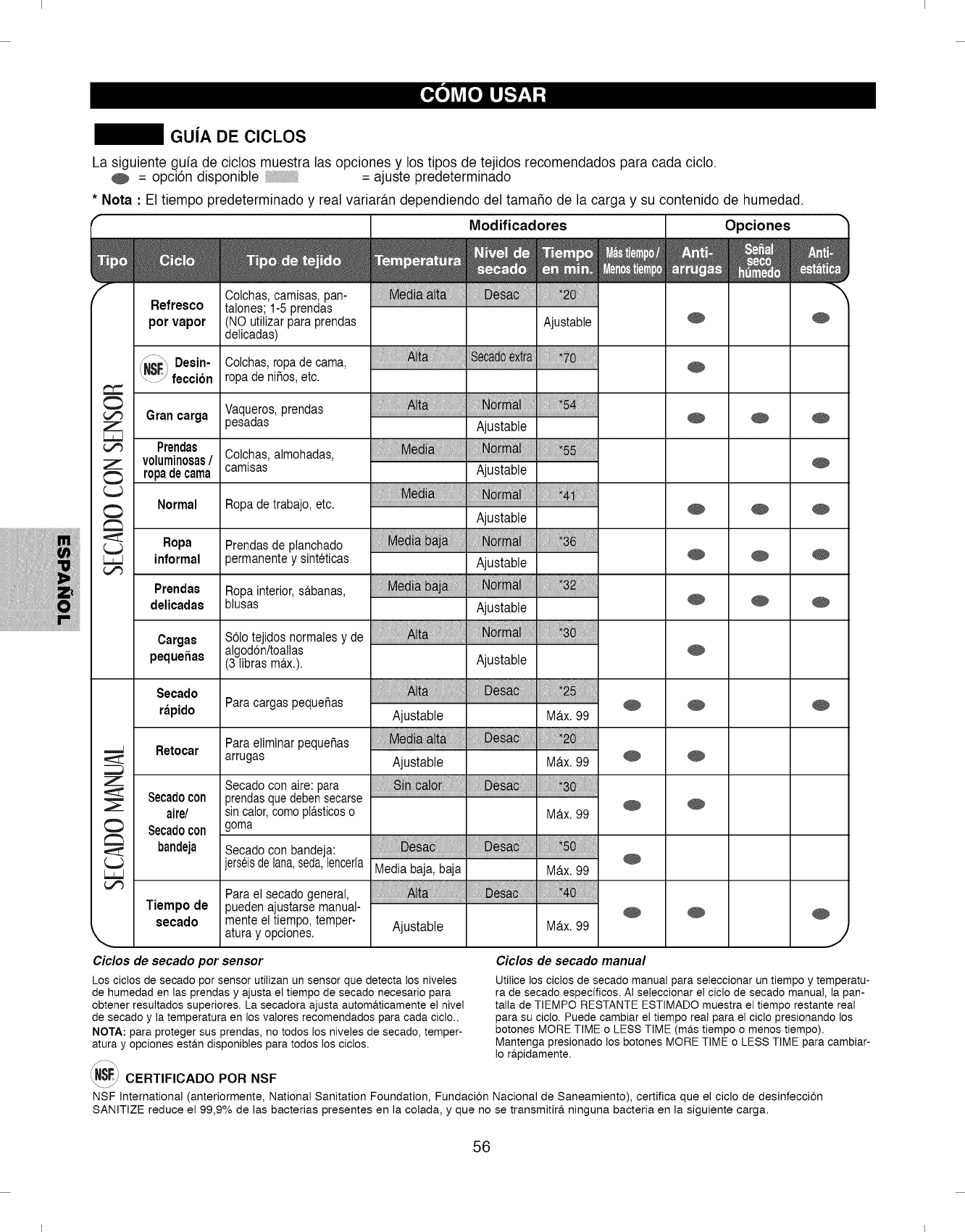
I I
GUJA DE ClCLOS
La siguiente guia de ciclos muestra las opciones y los tipos de tejidos recomendados para cada ciclo.
= opcien disponible = ajuste predeterminado
* Nota :El tiempo predeterminado y real variaran dependiendo del tamaSo de la carga y su contenido de humedad.
f- Modificadores Opciones
III ull;l,0, ° o
Colchas, camisas, pan- ....
Refresco talones; 1-5 prendas ....................................................................................................................................................................................................................
por vapor NO utilizar para prendas Ajustable _
delicadas)
i_S_ Desin-Colchas, ropa de cama,
_'Z'Y feccien rc3a de ni5os, etc.
Gran ¢arga Vaqueros, prendas
Z )esadas ................................................................................................................................Ajustable _ _
Prendas Oolchas, almohadas, ....
Zvoluminosas/ camisas Ajustable
ropa de cama
Normal Ropa de trabajo, etc. .... _ _
Ajustable
"_ Ropa Prendas de planchado
informal )ermanente y sinteticas Ajustable
....Prendas Ro )a interior, s_.banas,
delicadas blusas Ajustable
Carga8 Selo tejidos normales y de
algoden/toallas
peque_as 3 libras max.). Ajustable
Z
\
Secado : 5:1
Para cargas pequeRas Aiusiabie M_x99 _r_pido
ParaeliminarpequeRas : M _lt :i:i: : _ !: if:i::* il....
Retocar arrugas Ajustable M_.x. 99 _
Secado con aire: para
Secado con prendas que deben secarse _
aire/ sin calor, como p!_.sticos o M_.x. 99
Secado con goma
bandeja Secado con bandeja:
jers¢isdelana,seda,lencer/a
Tiempo de
secado
Para el secado general,
pueden ajustarse manual-
mente el tiempo, temper-
atura y opciones.
iil!liiiii!,!,i: iiii! iiiiil:!i i!iiiiiiil!liiiii!,!,!....
Media baj& baja MAx. 99
Ajustable M&x. 99
Ciclos de secado por sensor Ciclos de secado manual
Los ciclos de secado por sensor utilizan un sensor que detecta los niveles
de humedad en las prendas y ajusta e! tiempo de secado necesario para
obtener resultados superiores. La secadora ajusta autom&ticamente el nivel
de secado y la temperatura en los valores recomendados para cada ciclo..
NOTA: para proteger sus prendas, no todos los niveles de secado, temper-
atura y opciones est#.n disponibles para todos los ciclos.
_'--*" CERTIFICADO POR NSF
Utilice los ciclos de secado manual para seleccionar un tiempo y temperatu-
ra de secado especificos. AI seleccionar el ciclo de secado manual, la pan-
talla de TIEMPO RESTANTE ESTIMADO muestra el tiempo restante real
para su ciclo. Puede cambiar e! tiempo real para el ciclo presionando los
botones MORE TIME o LESS TIME (m#,s tiempo o menos tiempo).
Mantenga presionado los botones MORE TIME o LESS TIME para cambiar-
Io r#.pidamente.
NSF International (anteriormente, National Sanitation Foundation, Fundacien Nacional de Saneamiento), certifica que el ciclo de desinfeccien
SANITIZE reduce el 99,9% de las bacterias presentes en la colada, y que no se transmitir& ninguna bacteria en la siguiente carga.
56
I I
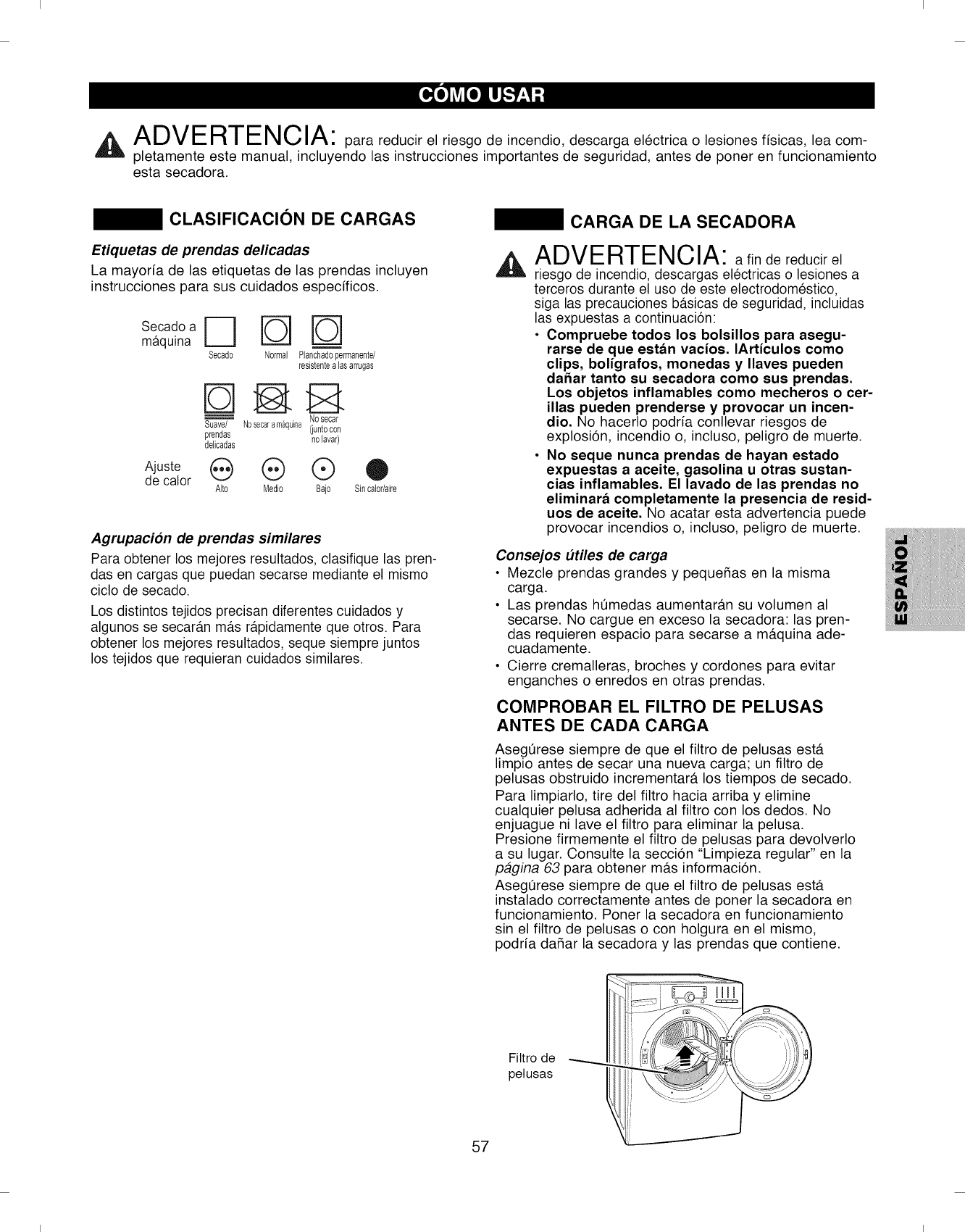
I I
A I-_\ II-- I_)-I-I-- I_ I f_ I A
/'_L/Vl-- !-I/I-- I_lbl/'_" para reducir el riesgo de incendio, descarga electrica o .esiones fisicas, lea com-
pletamente este manual, incluyendo las instrucciones importantes de seguridad, antes de poner en funcionamiento
esta secadora.
CLASIFICACION DE CARGAS
Etiquetas de prendas delicadas
La mayorfa de las etiquetas de las prendas incluyen
instrucciones para sus cuidados especfficos.
Se.cadoa [=_ _
maquna Secado Normal Planchadopermanente/
resistentealasarrugas
Nosecar
Suave/ Nosecaram_quina(juntocon
prendas nolavar)
delicadas
Ajuste (_ (_) Q O
de calor Alto Medio Bajo Sincalor/aire
Agrupacion de prendas similares
Para obtener los mejores resultados, clasifique las pren-
das en cargas que puedan secarse mediante el mismo
ciclo de secado.
Los distintos tejidos precisan diferentes cuidados y
algunos se secaran mas rapidamente que otros. Para
obtener los mejores resultados, seque siempre juntos
los tejidos que requieran cuidados similares.
CARGA DE LA SECADORA
ADVERTENCIA: afin de reducir el
riesgo de incendio, descargas electricas o lesiones a
terceros durante el use de este electrodomestico,
siga las precauciones basicas de seguridad, incluidas
las expuestas a continuaci6n:
• Compruebe todos los bolsillos para asegu-
rarse de que est&n vacios. IArticulos como
clips, boligrafos, monedas y Ilaves pueden
dahar tanto su secadora como sus prendas.
Los objetos inflamables como mecheros o cer-
illas pueden prenderse y provocar un incen-
dio. No hacerlo podria conllevar riesgos de
explosi6n, incendio o, incluso, peligro de muerte.
• No seque nunca prendas de hayan estado
expuestas a aceite, gasolina u otras sustan-
cias inflamables. El lavado de las prendas no
eliminar_ completamente la presencia de resid-
uos de aceite. No acatar esta advertencia puede
provocar incendios o, incluso, peligro de muerte.
Consejos utiles de carga
• Mezcle prendas grandes y pequeSas en la misma
carga.
• Las prendas hemedas aumentar#.n su volumen al
secarse. No cargue en exceso la secadora: las pren-
das requieren espacio para secarse a m#.quina ade-
cuadamente.
• Cierre cremalleras, broches y cordones para evitar
enganches o enredos en otras prendas.
COMPROBAR EL FILTRO DE PELUSAS
ANTES DE CADA CARGA
Aseg0rese siempre de que el filtro de pelusas est#.
limpio antes de secar una nueva carga; un filtro de
pelusas obstruido incrementar#, los tiempos de secado.
Para limpiarlo, tire del filtro hacia arriba y elimine
cualquier pelusa adherida al filtro con los dedos. No
enjuague ni lave el filtro para eliminar la pelusa.
Presione firmemente el filtro de pelusas para devolverlo
a su lugar. Consulte la secci6n "Limpieza regular" en la
pagina 63 para obtener m#.s informaci6n.
Aseg0rese siempre de que el filtro de pelusas est#.
instalado correctamente antes de porter la secadora en
funcionamiento. Poner la secadora en funcionamiento
sin el filtro de pelusas o con holgura en el mismo,
podria daSar la secadora y las prendas que contiene.
Fittro de
petusas
57
I I
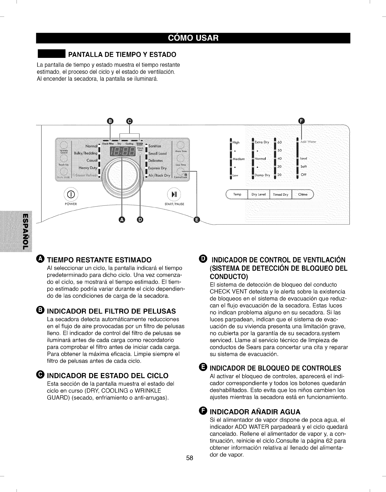
I I
PANTALLA DE TIEMPO Y ESTADO
La pantalla de tiempo y estado muestra el tiempo restante
estimado, el proceso del ciclo y el estado de ventilaci6n.
AI encender la secadora, la pantalla se iluminar&
POWER
High
IN Extra Dr I!!
,!oo
I !30 tSoff
20 m Off
O TIEMPO RESTANTE ESTIMADO
AI seleccionar un ciclo, la pantalla indicar#, el tiempo
predeterminado para dicho ciclo. Una vez comenza-
do el ciclo, se mostrar#, el tiempo estimado. El tiem-
po estimado podrfa variar durante el ciclo dependien-
do de las condiciones de carga de la secadora.
INDICADOR DEL FILTRO DE PELUSAS
La secadora detecta autom#.ticamente reducciones
en el flujo de aire provocadas por un filtro de pelusas
Ileno. El indicador de control del filtro de pelusas se
iluminar#, antes de cada carga como recordatorio
para comprobar el filtro antes de iniciar cada carga.
Para obtener la m#.xima eficacia. Limpie siempre el
filtro de pelusas antes de cada ciclo.
INDICADOR DE ESTADO DEL CICLO
Esta secci6n de la pantalla muestra el estado del
ciclo en curso (DRY, COOLING o WRINKLE
GUARD) (secado, enfriamiento o anti-arrugas).
58
OINDICADOR DE CONTROL DE VENTILACION
(SISTEMA DE DETECClON DE BLOQUEO DEL
CONDUCTO)
El sistema de detecci6n de bloqueo del conducto
CHECK VENT detecta y le alerta sobre la existencia
de bloqueos en el sistema de evacuaci6n que reduz-
can el flujo evacuaci6n de la secadora. Estas luces
no indican problema alguno en su secadora. Si las
luces parpadean, indican que el sistema de evac-
uaci6n de su vivienda presenta una limitaci6n grave,
no cubierta por la garantfa de su secadora.system
serviced. Llame al servicio tecnico de limpieza de
conductos de Sears para concertar una cita y reparar
su sistema de evacuaci6n.
OINDICADOR DE BLOQUEO DE CONTROLES
AI activar el bloqueo de controles, aparecer#, el indi-
cador correspondiente y todos los botones quedar#.n
deshabilitados. Esto evita que los nifios cambien los
ajustes mientras la secadora est#. en funcionamiento.
INDICADOR ANADIR AGUA
Si el alimentador de vapor dispone de poca agua, el
indicador ADD WATER parpadear#, y el ciclo quedar#.
cancelado. Rellene el alimentador de vapor y, a con-
tinuaci6n, reinicie el ciclo.Consulte la p#.gina 62 para
obtener informaci6n relativa al Ilenado del alimenta-
dor de vapor.
I I
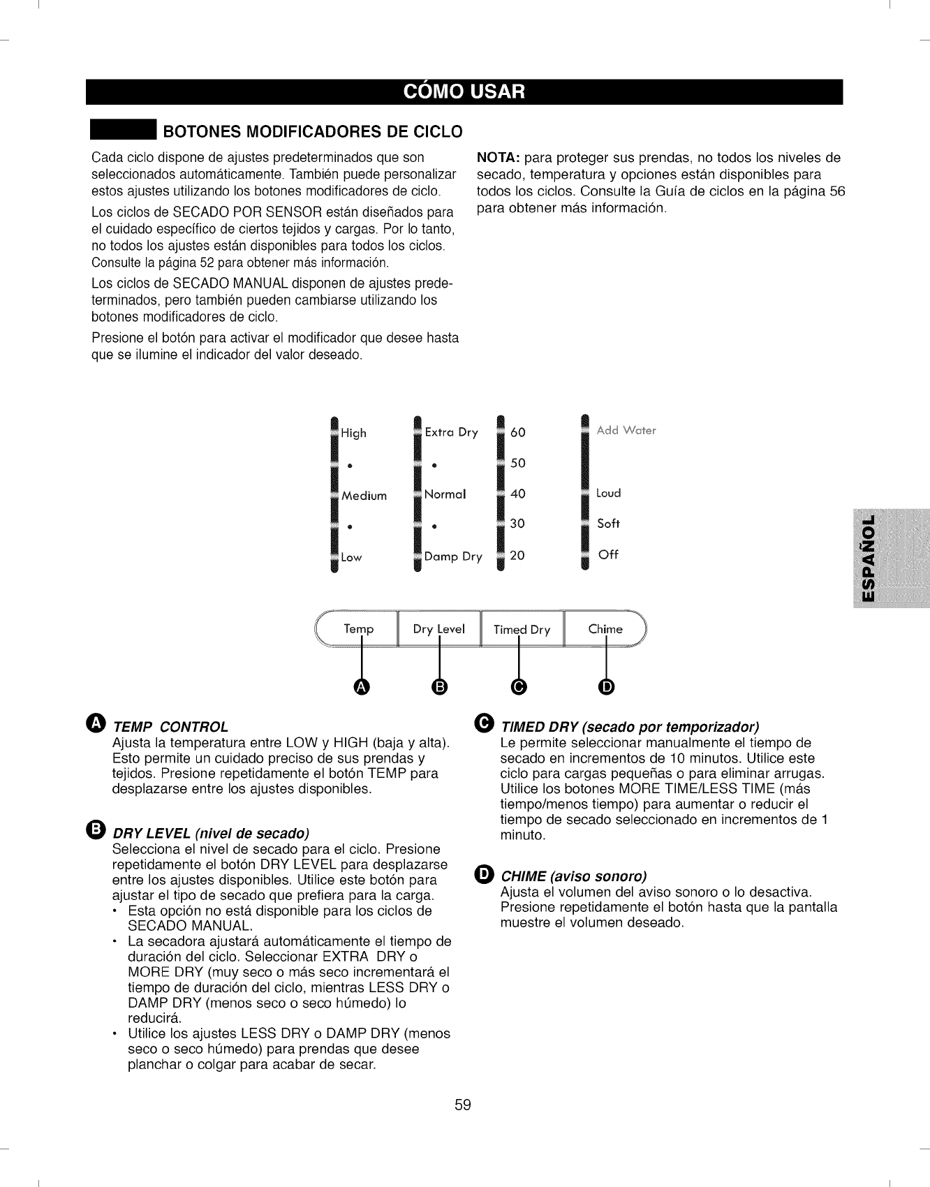
I I
BOTONES MODIFICADORES DE ClCLO
Cada ciclo dispone de ajustes predeterminados que son
seleccionados automaticamente. Tambien puede personalizar
estos ajustes utilizando los botones modificadores de ciclo.
Los ciclos de SECADO POR SENSOR estan diseSados para
el cuidado espedfico de ciertos tejidos y cargas. Por Io tanto,
no todos los ajustes estan disponibles para todos los ciclos.
Consutte la p_.gina52 para obtener m_.sinformaci6n.
Los ciclos de SECADO MANUAL disponen de ajustes prede-
terminados, pero tambien pueden cambiarse utilizando los
botones modificadores de ciclo.
Presione el bot6n para activar el modificador que desee hasta
que se ilumine el indicador del valor deseado.
NOTA: para proteger sus prendas, no todos los niveles de
secado, temperatura y opciones est#.n disponibles para
todos los ciclos. Consulte la Guia de ciclos en la p#.gina 56
para obtener m#.s informaci6n.
High
o
Medium
@
Low
Extra Dry
®
Normal
®
Damp Dry
60
50
40
30
20
Add _(,,/1 e r
Loud
Soft
Off
0TEMP CONTROL
Ajusta la temperatura entre LOW y HIGH (baja y alta).
Esto permite un cuidado preciso de sus prendas y
tejidos. Presione repetidamente el bot6n TEMP para
desplazarse entre los ajustes disponibles.
O
ODRY LEVEL (nivel de secado)
Selecciona el nivel de secado para el ciclo. Presione
repetidamente el bot6n DRY LEVEL para desplazarse
entre los ajustes disponibles. Utilice este bot6n para
ajustar el tipo de secado que prefiera para la carga.
• Esta opci6n no est#. disponible para los ciclos de
SECADO MANUAL.
• La secadora ajustar#, autom#.ticamente el tiempo de
duraci6n del ciclo. Seleccionar EXTRA DRY o
MORE DRY (muy seco o m_.s seco incrementar#, el
tiempo de duraci6n del ciclo, mientras LESS DRY o
DAMP DRY (menos seco o seco h0medo) Io
reducir&
• Utilice los ajustes LESS DRY o DAMP DRY (menos
seco o seco h0medo) para prendas que desee
planchar o colgar para acabar de secar.
O
TIMED DRY (secado por temporizador)
Le permite seleccionar manualmente el tiempo de
secado en incrementos de 10 minutos. Utilice este
ciclo para cargas peque_as o para eliminar arrugas.
Utilice los botones MORE TIME/LESS TIME (m#.s
tiempo/menos tiempo) para aumentar o reducir el
tiempo de secado seleccionado en incrementos de 1
minuto.
CHIME (aviso sonoro)
Ajusta el volumen del aviso sonoro o Io desactiva.
Presione repetidamente el bot6n hasta que la pantalla
muestre el volumen deseado.
59
I I
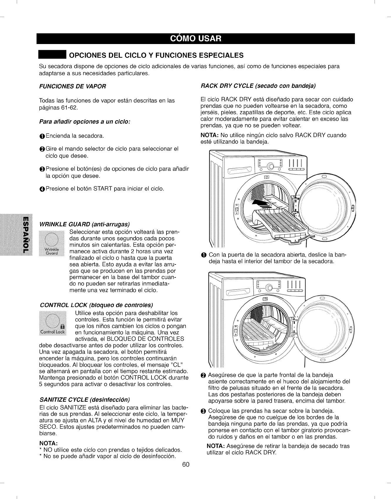
I I
OPCIONES DEL CICLO Y FUNCIONES ESPECIALES
Su secadora dispone de opciones de ciclo adicionales de varias funciones, asi como de funciones especiales para
adaptarse a sus necesidades particulares.
FUNCIONES DE VAPOR RACK DRY CYCLE (secado con bandeja)
Todas las funciones de vapor est#.n descritas en las
p#.ginas 61-62.
Para a_adir opciones a un cicIo:
O Encienda la secadora.
@Gire el mando selector de ciclo para seleccionar el
ciclo que desee.
OPresione el bot6n(es) de opciones de ciclo para aSadir
la opci6n que desee.
O Presione el bot6n START para iniciar el ciclo.
WRINKLE GUARD (anti-arrugas)
Seleccionar esta opci6n voltear_, las pren-
das durante unos segundos cada pocos
minutos sin calentarlas. Esta opci6n per-
manece activa durante 2 horas una vez
............................................................finalizado el ciclo o hasta que la puerta
sea abierta. Esto ayuda a evitar las arru-
gas que se producen en las prendas pot
permanecer en la base del tambor cuan-
do no pueden set retirarlas inmediata-
mente una vez terminado el ciclo.
El ciclo RACK DRY est#. diseSado para secar con cuidado
prendas que no pueden voltearse en la secadora, como
jerseis, pieles, zapatillas de deporte, etc. Este ciclo aplica
calor moderadamente para evitar calentar en exceso las
prendas, ya que no se pueden voltear.
NOTA: No utilice ningQn ciclo salvo RACK DRY cuando
este utilizando la bandeja.
o o
O Con la puerta de la secadora abierta, deslice la ban-
deja hasta el interior del tambor de la secadora.
CONTROL LOCK (bloqueo de controles)
Utilice esta opci6n para deshabilitar los
controles. Esta funci6n le permitir_, evitar
que los niSos cambien los ciclos o pongan
en funcionamiento la m_.quina. Una vez
activada, el BLOQUEO DE CONTROLES
debe desactivarse antes de poder utilizar los controles.
Una vez apagada la secadora, el bot6n permitir&
encender la m&quina, pero los controles continuar_.n
bloqueados. AI bloquear los controles, el mensaje "CL"
se alternate, en pantalla con el tiempo restante estimado.
Mantenga presionado el bot6n CONTROL LOCK durante
5 segundos para activar o desactivar los controles.
SANITIZE CYCLE (desinfeccion)
El ciclo SANITIZE est,. diseSado para eliminar las bacte-
rias de sus prendas. AI seleccionar este ciclo, la temper-
atura se ajusta en ALTA y el nivel de humedad en MUY
SECO. Estos ajustes predeterminados no pueden cam-
biarse.
NOTA:
* NO utilice este ciclo con prendas o tejidos delicados.
* No se puede aSadir vapor al ciclo de desinfecci6n.
60
O
AsegQrese de que la parte frontal de la bandeja
asiente correctamente en el hueco del alojamiento del
filtro de pelusas situado en el frente de la secadora.
Las dos pestaSas posteriores de la bandeja deben
apoyarse sobre la pared trasera, encima del tambor.
Coloque las prendas ha secar sobre la bandeja.
Asegerese de que no cuelgue de los bordes de la
bandeja ninguna parte de las prendas, ya que podrfa
ponerse en contacto con el tambor giratorio provocan-
do ruidos y daSos en el tambor o en las prendas.
NOTA" Asegerese de retirar la bandeja de secado tras
utilizar el ciclo RACK DRY.
I I

I I
FUNCIONES DE VAPOR
ADVERTENCIA"
• No abra la puerta de la secadora durante los ciclos
de vapor. El vapor puede provocar quemaduras
graves.
• No rellene el alimentador de vapor con gasolina, dis-
olventes de limpieza en seco u otras sustancias
inflamables o explosivas.Estas desprenden vapores
que podr[an explotar.
• No beba agua procedente del alimentador de vapor.
• No rellene el alimentador de vapor con agua caliente
(por encima de los 86° F/30° C)
• No toque la boquilla de vapor ubicada en el tambor
durante o tras el ciclo de vapor.
ACERCA DEL VAPOR
La tecnologia de vapor permite aplicar en los tejidos un
chorro de vapor caliente en remolino para eliminar las
arrugas y desodorizar las prendas mediante el ciclo
STEAM REFRESH (refresco por vapor). Ademas, el vapor
puede utilizarse en muchos otros ciclos para ayudar a
prevenir la acumulaci6n de electricidad estatica el final del
ciclo.
El ciclo STEAM REFRESH refrescara entre 1 y 5 prendas.
Para obtener los mejores resultados, utilice este ciclo en
prendas de tamaSo y tejido similares. Los mejores
resultados se obtienen en prendas con mezcla 70/30 de
algod6n/poliester.
Utilizacion del cicIo STEAM REFRESH
(refresco por vapor)
El ciclo STEAM REFRESH utiliza 0nicamente el poder del
vapor para reducir de forma rapida las arrugas y el olor
de los tejidos. Deja como nuevas prendas arrugadas
guardadas durante mucho tiempo y permite un planchado
mas sencillo de prendas muy arrugadas. El ciclo STEAM
REFRESH tambien puede utilizarse para ayudar a reducir
olores en las prendas, como la ropa que ha estado
expuesta a espacios de fumadores.
Este ciclo puede refrescar entre 1 y 5 prendas o una
prenda voluminosa como una colcha. Los mejores resul-
tados se obtienen en prendas mezcla de
algod6n/poliester.
NOTA: la opci6n STATIC SHIELD (anti-estatica) puede
utilizarse junto con el ciclo STEAM REFRESH (refresco
por vapor) para ayudar a prevenir la electricidad estatica.
O
O
O
Encienda la secadora y gire el mando selector de ciclo
hasta seleccionar STEAM REFRESH.
Si Io desea, selecccione la opci6n STATIC SHIELD.
El n0mero predeterminado de prendas es 3. Presione
el bot6n MORE TIME o LESS TIME para seleccionar
el n0mero de prendas que contiene la carga.
Seleccione b19para refrescar prendas voluminosas
como colchas.
OPresione el botOn START/PAUSE para iniciar el ciclo.
NOTA: El ciclo STEAM REFRESH selecciona automatica-
mente la funci6n WRINKLE GUARD (anti-arrugas)
para evitar que se produzcan arrugas en las pren-
das si no las retira de la secadora inmediatamente
tras terminar el ciclo. 61
NOTAS IMPORTANTES ACERCA DE LOS CICLOS
DE VAPOR:
• El vapor podria no ser claramente visible durante los
ciclos en los que se utiliza. Esto se considera normal.
• No utilice el ciclo STEAM REFRESH con prendas
como jerseis de lana, chaquetas de cuero, seda,
prendas mojadas, lenceria, productos de espuma o
mantas electricas.
• Para obtener los mejores resultados, introduzca
prendas de tamafio y tejido similares. No sobrecargue
la m#.quina.
• Cuando el filtro/conducto est#. obstruido, la opci6n de
vapor podria no proporcionar resultados 6ptimos.
• Cuando una funci6n de vapor este en uso, el tambor
se detendr#, para permitir que el vapor permanezca
dentro.
• El alimentador de vapor d.ebe rellenarse con agua
hasta la linea de nivel MAX. De Io contrario,
aparecer#, un mensaje de error en pantalla.
• Si el conducto de evacuaci6n est#. restringido o el
filtro de pelusas no est#. limpio, los ciclos u opciones
de vapor podrian no proporcionar los resultados
adecuados. Consulte las p#.ginas 50 y 51 para
obtener los requisitos de ventilaci6n.
Utilizacion de la opcion STATIC SHIELD
(anti-estatica)
Esta opci6n inyecta vapor al final del ciclo
de secado para reducir la electricidad
est#.tica generada por el roce de tejidos
secos. Cambie el tiempo de duraci6n del
ciclo presionando los botones MORE TIME y LESS
TIME (m#.s tiempo y menos tiempo) hasta que la pan-
talla muestre el n0mero de prendas que conforman la
carga.
La opci6n STATIC SHIELD (anti-est#.tica) puede uti-
lizarse con los ciclos NORMAL, BULKY/BEDDING,
HEAVY DUTY, CASUAL, DELICATES, EXPRESS DRY,
TIMED DRY (normal, prendas voluminosas/ropa de
cama, gran carga, ropa informal, prendas delicadas,
secado r#.pido, tiempo de secado).
NOTAS:
• AI afiadir la opci6n STATIC SHIELD a los ciclos de
secado con sensor, no pueden seleccionarse los nive-
les de secado LESS y DAMP.
• La opci6n STATIC SHIELD puede utilizarse con los
ciclos TIMED DRY (secado por temporizador).
• Tras seleccionar la opci6n STATIC SHIELD en TIMED
DRY, los botones MORE TIME y LESS TIME s61o cam-
biar#.n el tiempo del vapor.
• Una vez comenzado el ciclo, los botones MORE TIME
y LESS TIME quedar#.n deshabilitados.
I I
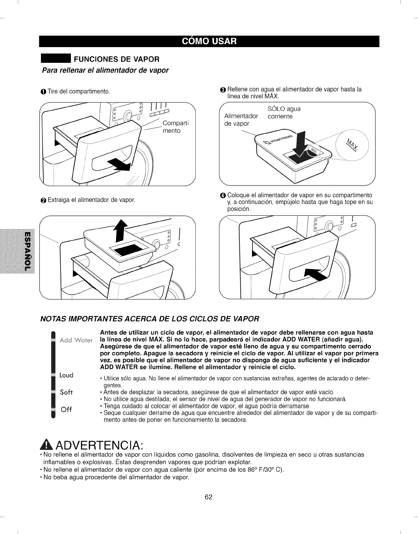
I I
FUNCIONES DE VAPOR
Para rellenar el alimentador de vapor
OTire del compartimento.
OExtraiga el alimentador de vapor.
mento
ORellene con agua el alimentador de vapor hasta la
Ifnea de nivel MAX.
SOLO agua
Alimentador corriente
de vapor
\
@Coloque el alimentador de vapor en su compartimento
y, a continuaci6n, empt]jelo hasta que haga tope en su
posici6n.
NOTAS IMPORTANTES ACERCA DE LOS CICLOS DE VAPOR
Add Water
Loud
Soft
Off
Antes de utilizar un ciclo de vapor, el alimentador de vapor debe rellenarse con agua hasta
la linea de nivel MAX. Si no Io hace, parpadeard el indicador ADD WATER (afiadir agua).
Aseg0rese de que el alimentador de vapor este Ileno de agua y su compartimento cerrado
pot completo. Apague la secadora y reinicie el ciclo de vapor. AI utilizar el vapor pot primera
vez, es posible que el alimentador de vapor no disponga de agua suficiente y el indicador
ADD WATER se ilumine. Rellene el alimentador y reinicie el ciclo.
•Utilice s61oagua. No Ilene et atimentador de vapor con sustancias extraSas,agentes de actarado o deter-
gentes.
• Antes de desplazar la secadora, asegt]rese de que el alimentador de vapor este vado.
• No utilice agua destilada; el sensor de nivel de agua del generador de vapor no funcionara.
• Tenga cuidado al colocar el alimentador de vapor; el agua podrfa derramarse.
• Seque cualquier derrame de agua que encuentre alrededor del alimentador de vapor y de su comparti-
mento antes de poner en funcionamiento la secadora.
ADVERTENClA"
• No rellene el alimentador de vapor con Ifquidos como gasolina, disolventes de limpieza en seco u otras sustancias
inflamables o explosivas. Estas desprenden vapores que podrfan explotar.
• No rellene el alimentador de vapor con agua caliente (por encima de los 86° F/30° C).
• No beba agua procedente del alimentador de vapor.
62
I I
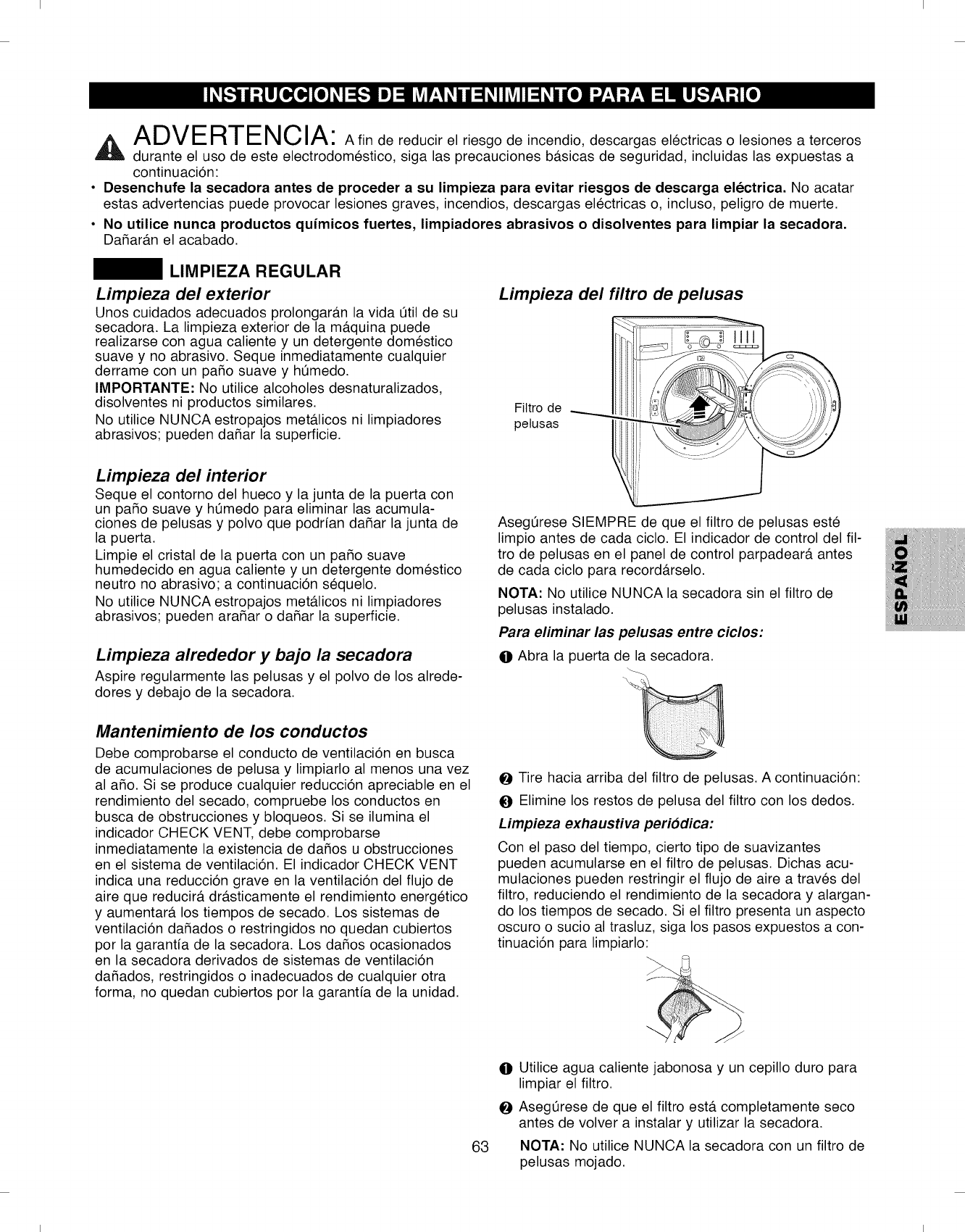
I I
AI-_\ iI-- l_Y-l-l-- I%i f_ iA
,i_ /IIJVI- FIll- I_ILJl/I" A fin de reducir el riesgo de incendio, descargas electricas o lesiones a terceros
durante el uso de este electrodomestico, siga las precauciones b#.sicas de seguridad, incluidas las expuestas a
continuaci6n:
• Desenchufe la secadora antes de proceder a su limpieza para evitar riesgos de descarga electrica. No acatar
estas advertencias puede provocar lesiones graves, incendios, descargas electricas o, incluso, peligro de muerte.
•No utilice nunca productos quimicos fuertes, limpiadores abrasivos o disolventes para limpiar la secadora.
DaSar#.n el acabado.
LIMPIEZA REGULAR
Limpieza del exterior
Unos cuidados adecuados prolongar#.n la vida 0til de su
secadora. La limpieza exterior de la m#.quina puede
realizarse con agua caliente y un detergente domestico
suave y no abrasivo. Seque inmediatamente cualquier
derrame con un paso suave y htJmedo.
IMPORTANTE: No utilice alcoholes desnaturalizados,
disolventes ni productos similares.
No utilice NUNCA estropajos met#.licos ni limpiadores
abrasivos; pueden daSar la superficie.
Limpieza del interior
Seque el contorno del hueco y la junta de la puerta con
un paso suave y htJmedo para eliminar las acumula-
ciones de pelusas y polvo que podrian da_ar la junta de
la puerta.
Limpie el cristal de la puerta con un paso suave
humedecido en agua caliente y un detergente domestico
neutro no abrasivo; a continuaci6n sequelo.
No utilice NUNCA estropajos met_.licos ni limpiadores
abrasivos; pueden ara_ar o da_ar la superficie.
Limpieza alrededor y bajo la secadora
Aspire regularmente las pelusas y el polvo de los alrede-
dores y debajo de la secadora.
Mantenimiento de los conductos
Debe comprobarse el conducto de ventilaci6n en busca
de acumulaciones de pelusa y limpiarlo al menos una vez
al a_o. Si se produce cualquier reducci6n apreciable en el
rendimiento del secado, compruebe los conductos en
busca de obstrucciones y bloqueos. Si se ilumina el
indicador CHECK VENT, debe comprobarse
inmediatamente la existencia de da_os u obstrucciones
en el sistema de ventilaci6n. El indicador CHECK VENT
indica una reducci6n grave en la ventilaci6n del flujo de
aire que reducir#, dr#.sticamente el rendimiento energetico
y aumentar_, los tiempos de secado. Los sistemas de
ventilaci6n daSados o restringidos no quedan cubiertos
por la garantia de la secadora. Los daSos ocasionados
en la secadora derivados de sistemas de ventilaci6n
daSados, restringidos o inadecuados de cualquier otra
forma, no quedan cubiertos por la garantia de la unidad.
Limpieza del filtro de pelusas
Fittro de
petusas
AsegtJrese SIEMPRE de que el filtro de pelusas este
limpio antes de cada ciclo. El indicador de control del ill-
tro de pelusas en el panel de control parpadear#, antes
de cada ciclo para record#.rselo.
NOTA: No utilice NUNCA la secadora sin el filtro de
pelusas instalado.
Para eliminar las pelusas entre ciclos:
O Abra la puerta de la secadora.
_1 Tire hacia arriba del filtro de pelusas. A continuaci6n:
_) Elimine los restos de pelusa del filtro con los dedos.
Limpieza exhaustiva periodica:
Con el paso del tiempo, cierto tipo de suavizantes
pueden acumularse en el filtro de pelusas. Dichas acu-
mulaciones pueden restringir el flujo de aire a traves del
filtro, reduciendo el rendimiento de la secadora y alargan-
do los tiempos de secado. Si el filtro presenta un aspecto
oscuro o sucio al trasluz, siga los pasos expuestos a con-
tinuaci6n para limpiarlo:
63
0 Utilice agua caliente jabonosa y un cepillo duro para
limpiar el filtro.
AsegtJrese de que el filtro est#. completamente seco
antes de volver a instalar y utilizar la secadora.
NOTA: No utilice NUNCA la secadora con un filtro de
pelusas mojado.
I I
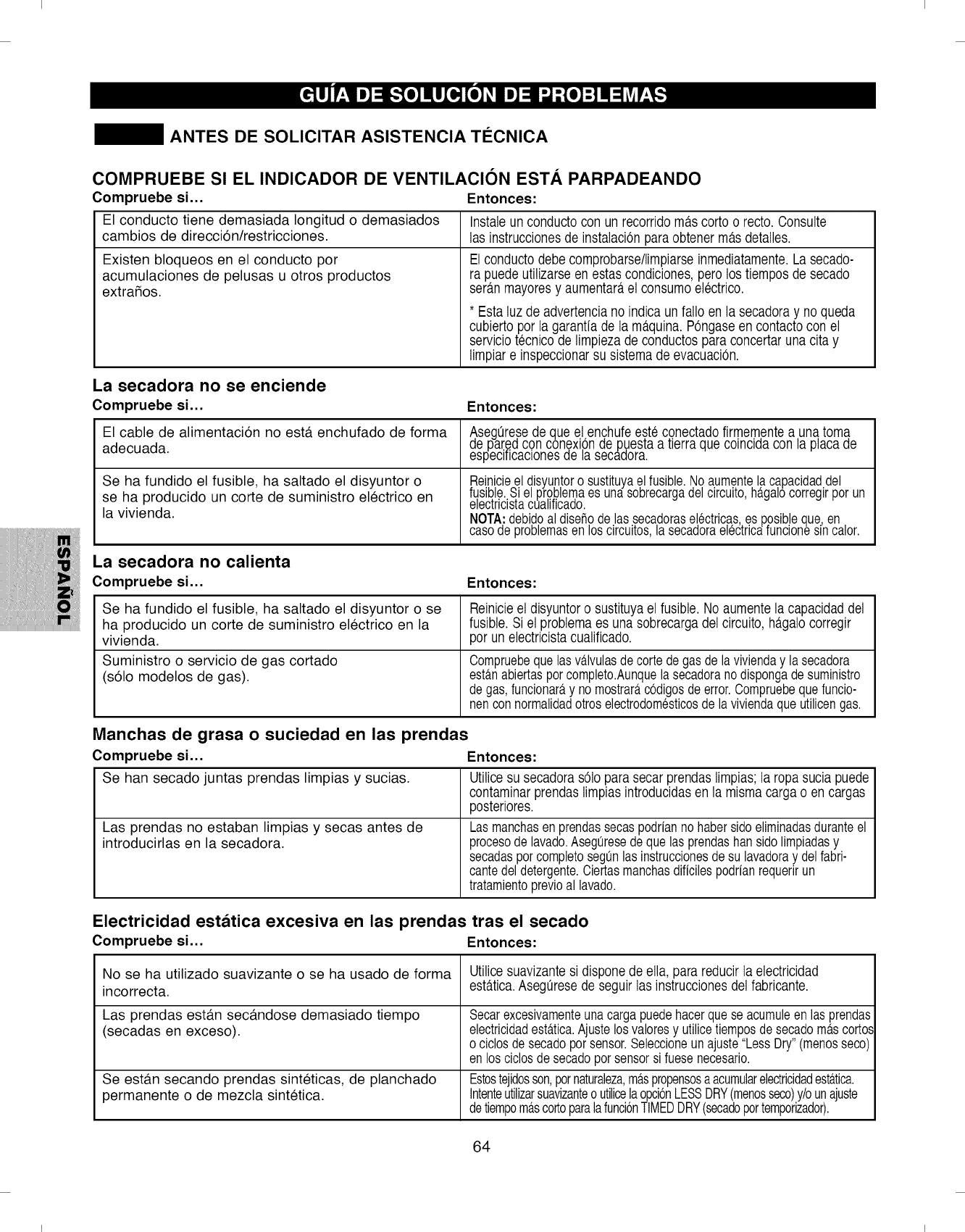
I I
ANTES DE SOLICITAR ASISTENCIA TI_CNICA
COMPRUEBE SI EL INDICADOR DE VENTILACION EST.& PARPADEANDO
Compruebe si... Entonces:
El conducto tiene demasiada Iongitud o demasiados Instaleun conductocon un recorridoma.scorto o recto.Consulte
cambios de direcci6n/restricciones, las instruccionesde instalaciOnparaobtener ma.sdetalles.
Existen bloqueos en el conducto por
acumulaciones de pelusas u otros productos
extrafios.
El conductodebecomprobarse/limpiarseinmediatamente.Lasecado-
ra puedeutilizarseen estas condiciones,pero los tiemposde secado
sera.nmayoresy aumentara,el consumoelectrico.
* Estaluz de advertenciano indica un folio en la secadoray no queda
cubiertopor lagarantia de la ma.quina.POngaseen contactocon el
serviciotecnicode limpiezade conductosparaconcertaruna cita y
limpiare inspeccionarsu sistemade evacuaciOn.
La secadora no se enciende
Compruebe si...
El cable de alimentaci6n no est,. enchufado de forma
adecuada.
Se ha fundido el fusible, ha saltado el disyuntor o
se ha producido un corte de suministro electrico en
la vivienda.
Entonces:
AesegQresede que el enchufeesteconectadofirmementeauna toma
par..eacon conexlpn ae pues[aa [lerraque colnclaacon la placa ae
especlTicaclonesae la secaaora.
Reinicieeldisyuntoro sustituyaelfusible.Noaumentelacapacidad.del
sible,b[iel prooblemaes unasoDrecargadelclrculto,nagalocorreglrporun
ec[rlClS[acuallTiCaoo.
NOTA:debi,doal disefiodelas seca,dorase[ectricas,es posibleque,en,
casoaeprodemasen os c rculos, a secaaoraeec[rca funcones nca or.
La secadora no calienta
Compruebe si...
Se ha fundido el fusible, ha saltado el disyuntor o se
ha producido un corte de suministro electrico en la
vivienda.
Suministro o servicio de gas cortado
(sOlo modelos de gas).
Entonces:
Reinicieel disyuntoro sustituyael fusible.No aumentela capacidaddel
fusible.Si el problemaes una sobrecargadel circuito,ha.galocorregir
por unelectricistacualificado.
Compruebequelasva.lvulasde cortedegas delavivienday lasecadora
esta.nabiertasporcompleto.Aunquela secadoranodispongade suministro
degas,funcionara,y nomostrara,codigosdeerror.Compruebequefuncio-
nencon normalidadotroselectrodomesticosdela viviendaque utilicengas.
Manchas de grasa o suciedad en las prendas
Compruebe si... Entonces:
Se han secado juntas prendas limpias y sucias.
Las prendas no estaban limpias y secas antes de
introducirlas en la secadora.
Utilicesu secadorasolo parasecar prendaslimpias;la ropasucia puede
contaminarprendas limpiasintroducidasen la misma cargo o en cargos
posteriores.
Lasmanchasenprendassecaspodrianno habersidoeliminadasduranteel
procesode lavado.Aseguresedeque lasprendashansidolimpiadasy
secadasporcompletosegunlas instruccionesdesu lavadoray delfabri-
cantedel detergente.Ciertasmanchasdificilespodrianrequerirun
tratamientoprevioal lavado.
Electricidad estatica excesiva en las prendas tras el secado
Compruebe si... Entonces:
No se ha utilizado suavizante o se ha usado de forma
incorrecta.
Las prendas est#.n sec#.ndose demasiado tiempo
(secadas en exceso).
Se est#.n secando prendas sinteticas, de planchado
permanente o de mezcla sintetica.
64
Utilicesuavizantesi disponede ella, para reducirla electricidad
esta.tica.Asegt_resede seguirlas instruccionesdel fabricante.
Secarexcesivamenteunacargapuedehacerquese acumuleen lasprendas
electricidadesta.tica.Ajustelosvaloresy utilicetiemposde secadoma.scorto._
ociclosdesecadoporsensor.Seleccioneunajuste"LessDry"(menosseco
enlos ciclosdesecadoporsensorsi fuesenecesario.
Estostejidosson,potnaturaleza,m_.spropensosaacumularelectricidadest_.tica.
Intenteutilizarsuavizanteo utilicelaopci6nLESSDRY(menosseco)y/ounajuste
detiempom_.scortoparalafunci6nTIMEDDRY(secadopottemporizador).
I I
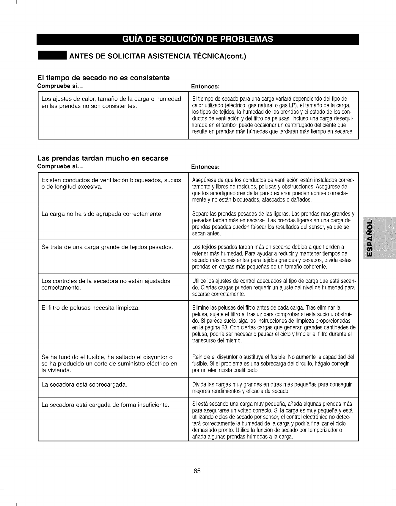
I I
ANTES DE SOLICITAR ASISTENCIA Tl_CNICA(cont.)
El tiempo de secado no es consistente
Compruebe si... Enton ces:
Los ajustes de calor, tamaSo de la carga o humedad
en las prendas no son consistentes.
Eltiempo de secadopara unacarga variara,dependiendodel tipo de
calor utilizado(electrico,gas natural o gas LP), eltamaho de la carga,
los tipos detejidos, la humedadde las prendasy el estadode los con-
ductosde ventilaciOny del filtrode pelusas. Inclusounacarga desequi-
libradaen el tamborpuedeocasionarun centrifugadodeficienteque
resulteen prendasma.shQmedasque tardara.nma.stiempoen secarse.
Las prendas tardan mucho en secarse
Compruebe si... Enton ces:
Existen conductos de ventilaci6n bloqueados, sucios
o de Iongitud excesiva.
La carga no ha sido agrupada correctamente.
Se trata de una carga grande de tejidos pesados.
Los controles de la secadora no est#.n ajustados
correctamente.
El filtro de pelusas necesita limpieza.
Se ha fundido el fusible, ha saltado el disyuntor o
se ha producido un corte de suministro electrico en
la vivienda.
AsegQresede que los conductosdeventilaciOnesta.ninstaladoscorrec-
tamente y libres de residuos,pelusasy obstrucciones.AsegQresede
que los amortiguadoresde la paredexteriorpuedenabrirse correcta-
mentey no esta.nbloqueados,atascadoso dahados.
Separelas prendas pesadasde las ligeras.Las prendas ma.sgrandesy
pesadastardan ma.sen secarse.Las prendasligeras en unacarga de
prendaspesadaspuedenfalsear los resultadosdel sensor,ya que se
secanantes.
Los tejidospesadostardan ma.sen secarse debidoa quetienden a
retenerma.shumedad.Paraayudara reduciry mantenertiempos de
secadoma.sconsistentesparatejidos grandesy pesados,divida estas
prendasen cargasma.spequehasde un tamahocoherente.
Utilicelos ajustesde control adecuadosal tipo de carga que esta.secan-
do. Oiertascargas puedenrequerirunajuste del nivel de humedadpara
secarsecorrectamente.
Eliminelas pelusasdel filtro antesde cada carga. Traseliminarla
pelusa,sujeteel filtro al trasluz paracomprobarsiesta, sucio u obstrui-
do. Si parecesucio, siga las instruccionesde limpiezaproporcionadas
en la pa.gina63. Con ciertascargasque generangrandescantidadesde
pelusa,podriaser necesariopausar el ciclo y limpiarel filtro duranteel
transcursodel mismo.
Reinicieel disyuntoro sustituyael fusible. No aumentela capacidaddel
fusible.Si el problemaes una sobrecargadel circuito,ha.galocorregir
por unelectricistacualificado.
La secadora est#. sobrecargada. Dividalas cargas muygrandesen otras ma.spequehasparaconseguir
mejoresrendimientosy eficaciade secado.
La secadora est#. cargada de forma insuficiente. Siesta.secandouna carga muy pequeha,ahada algunasprendas ma.s
paraasegurarseunvolteo correcto.Si la carga es muy pequehay esta.
utilizandociclos de secadopor sensor,el controlelectrOnicono detec-
tara.correctamentela humedadde la carga y podria finalizarel ciclo
demasiadopronto.Utilice la funciOnde secadoportemporizadoro
ahadaalgunasprendas ht_medasa lacarga.
65
I I
I I
ANTES DE SOLICITAR ASISTENCIA TI_CNICA (cont.)
Las prendas estan arrugadas
Compruebe si...
Las prendas est#.n sec#.ndose demasiado tiempo
(secadas en exceso).
Las prendas hart permanecido en la secadora
demasiado tiempo una vez terminado el ciclo.
Entonces:
Secarunacargaenexcesopuedeproducirarrugasenlas prendas.
Intenteutilizaruntiempodesecadoma.scortoo utilicelaopcionLESS
DRYy retirelas prendasmientrasaunretienenunpocodehumedad.
UtilicelaopcionWRINKLEGUARD(anti-arrugas).Estafuncionhara.girar
brevementelas prendascadapocosminutesy durante2 horasparaayudar
aprevenirlasarrugas.
Las prendas han encogido
Compruebe si... Entonces:
Las instrucciones para el cuidado de las prendas no
se han tenido en cuenta. Paraevitarquelasprendasencojan,sigaatentamentelasinstruccionesrel-
ativasalcuidadodesusprendas,yaqueciertostejidosencojendeforma
naturalal ser lavados.Otrotipodetejidospuedenlavarse,peroencogenal
secarsea ma.quina.No usecaloro utiliceunajustemenory/olafuncion
RACKDRY(secadoconbandeja)si disponedeelias.
La pantalla muestra el codigo de error TEl 6TE2
Compruebe si... Entonces:
I La detecci6n de temperatura falla. Apague la secadora solicite asistencia tecnica.
YI
Pelusa sobre las prendas
Compruebe si...
El filtro de pelusas no se ha limpiado correctamente.
Las prendas no se han agrupado correctamente.
Las prendas acumulan un exceso de electricidad
est_.tica.
Entonces:
Eliminelas pelusasdelfiltroantesde cadacarga.Traseliminarla pelusa,
sujeteel filtroal trasluzparacomprobarsi esta.suciou obstruido.Siparece
sucio,sigalas instruccionesdelimpiezaproporcionadasen lapa.gina63.
Conciertascargasquegenerangrandescantidadesde pelusa,podriaser
necesariolimpiarelfiltroduranteel transcursodelciclo.
Ciertostejidosproducenpelusa(porejemplo,unatoallade algodonblanco)y
debensecarseseparadasde otrasquetienenfacilidadparaatraparla(por
ejemplo,unospantalonesde linenegro).
•Utilicesuavizanteparareducirlaelectricidadesta.tica.Aseguresede
seguirlas instruccionesdelfabricante.
• Secarexcesivamenteunacargapuedehacerquese acumuleen las
prendaselectricidadesta.tica.Ajustelosvaloresy utilicetiemposdeseca-
doma.scorteso ciclosdesecadoporsensor.
La secadora est#. sobrecargada. Dividalas cargasmuygrandesenotrasma.speque5asparasecarlas.
Ha olvidado paSuetosde papet, papet,etc. en los bolsiltos. Busqueafondoenlosbolsillosantesdeprocederallavadoosecadodelasprendas.
66
I I
I I
ANTES DE SOLICITAR ASISTENCIA TI_CNICA (cont.)
Las funciones de vapor no estan operativas
Compruebe si... Entonces:
No se genera vapor y la pantalla no muestra c6digos
de error.
Las prendas siguen estando arrugadas al terminar
el ciclo STEAM REFRESH (refresco por vapor).
No existen arrugas en las prendas tras utilizar el
ciclo STEAM REFRESH.
Existen gotas de agua en la puerta durante los
ciclos de vapor.
El tambor no gira durante los ciclos de vapor.
No puede verse el vapor al comienzo del ciclo.
El vapor se libera en distintos perfodos del ciclo
para cada opci6n.
Compruebe si se produce condensaci6n en el interior de la
puerta durante la vaporizaci6n del ciclo. El vapor no resulta
claramente visible. Esto se considera normal.
Compruebe el compartimento del alimentador de vapor:
(1) AsegQrese de que el alimentad.or de vapor est#. Ileno de
agua hasta la Ifnea de nivel MAX.
(2) AsegQrese de que el alimentador de vapor este asenta-
do correctamente y que su compartimento este cerrado
por completo.
(3) Encienda y apague la secadora; a continuaci6n, reinicie
el ciclo de vapor.
NO UTILICE AGUA DESTILADA: los sensores de nivel de
agua del generador de vapor no funcionar#.n.
La bomba del alimentador de vapor no funciona: solicite
asistencia tecnica.
Cargue Qnicamenteentre 1y 5 prendas (excepto prendas volumi-
nosas individuales). No mezcle distintos de tejidos.
El ciclo STEAM REFRESHes mas eficaz en tejidos con mezcla
70/30 de algod6n/poliester.No utilice prendas de algod6n 100%.
Este ciclo est,. dise_ado para etiminar las arrugas. Si,tras el ciclo
STEAM REFRESH, desea crear rayas o marcas en sus prendas,
deber_,planchartaspara que asf sea.
El vapor en invisible. Sin embargo, bajo ciertas condiciones, la nube
condensada puede verse o puede formarse condensaci6n en el inte-
rior det cristal de la puerta.
El tambor se detiene para que el vapor permanezca en et mismo.
El tambor girard,s6to durante unos segundos cada minuto.
El vapor se libera en distintos perfodos del ciclo para cada opci6n.
El vapor no puede verse, pero podrfa formarse condensaci6n en et
interior de la puerta al generarse vapor.
Atgunos olores son diffciles de etiminar. Los tejidos que contengan
ciertos olores diffcites de etiminar o muy fuertes, podrfan no refres-
carse correctamentey requerir ser lavadas o limpiadas en seco.
67
I I
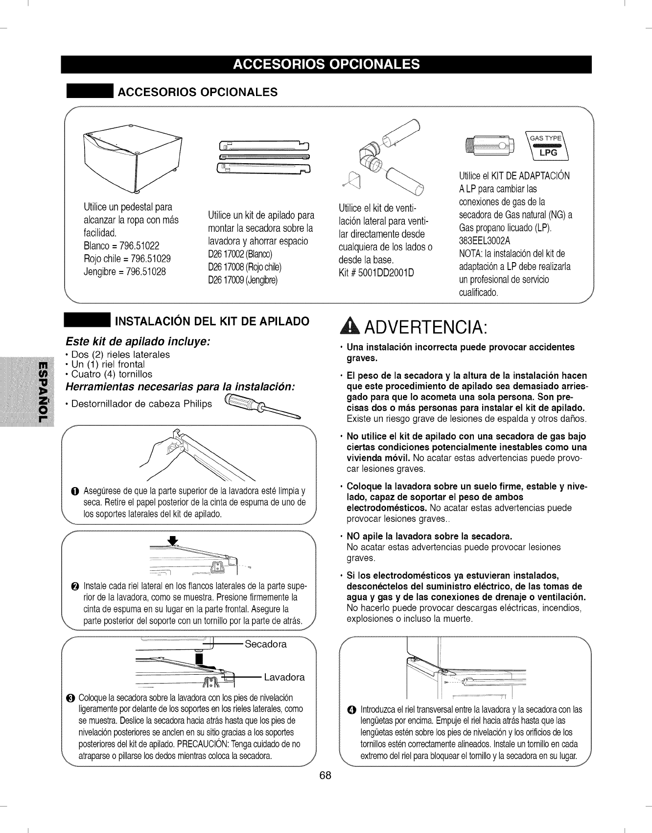
I I
ACCESORIOS OPCIONALES
Utiticeun pedestalpara
alcanzarla ropacon m_.s
facitidad.
Btanco= 796.51022
Rojochile = 796.51029
Jengibre = 796.51028
"7
Utilice un kit de apitado para
montar la secadorasobre la
lavadoray ahorrar espacio
D2617002(Blanco)
D2617008(Rojochile)
D2617009(Jengibre)
Utiticeet kit deventi-
laci6n lateralpara venti-
lar directamentedesde
cualquiera de los ladeso
desde la base.
Kit # 5001DD2001D
Utiliceel KITDEADAPTACION
ALP paracambiarlas
conexionesde gasde la
secadorade Gasnatural(NG)a
Gas propanolicuado(LP).
383EEL3002A
NOTA:la instalacbndelkitde
adaptaciOna LPdeberealizarla
un profesionalde servicio
cualificado.
INSTALACION DEL KIT DE APILADO
Este kit de apilado incluye:
• Dos (2) rieles laterales
• Un (1) riel frontal
• Cuatro (4) tornillos
Herramientas necesarias para la instalacion:
• Destornillador de cabeza Philips
O Aseguresedequela partesuperiorde la lavadoraestelimpiay
seca.Retireel papelposteriorde lacintadeespumade unode
lossoporteslateralesdel kitdeapilado.
f_
Instalecadariellateralen losflancoslateralesde la partesupe-
riordela lavadora,comose muestra.Presionefirmementela
cintadeespumaen su lugarenla partefrontal.Asegurela
parteposteriordelsoportecon untornilloporla partede atra.s.
J
'f .............................._ Secadora
Lavadora
O Coloquelasecadorasobrelalavadoraconlospiesdenivelacbn
ligeramentepordelantedelossoportesenlosrieleslaterales,como
semuestra.Deslicelasecadorahaciaatra.shastaquelospiesde
nivelacbnposterioresseanclenensusitiograciasa lossoportes
posterioresdelkitdeapilado.PRECAUCION:Tengacuidadodeno
atraparseo pillarselosdedosmientrascolocalasecadora.
68
ADVERTENClA:
Una instalacibn incorrecta puede provocar accidentes
graves.
El peso de la secadora y la altura de la instalacibn hacen
que este procedimiento de apilado sea demasiado arries-
gado para que Io acometa una sola persona. Son pre-
cisas dos o mas personas para instalar el kit de apilado.
Existe un riesgo grave de lesiones de espatda y otros da_os.
No utilice el kit de apilado con una secadora de gas bajo
ciertas condiciones potencialmente inestables como una
vivienda mbvil. No acatar estasadvertencias puede prove-
car lesiones graves.
Coloque la lavadora sobre un suelo firme, estable y nive-
lado, capaz de soportar el peso de ambos
electrodomesticos. No acatar estas advertencias puede
provocar lesiones graves..
NO apile la lavadora sobre la secadora.
No acatar estas advertencias puede provocar lesiones
graves.
Si los electrodomesticos ya estuvieran instalados,
desconectelos del suministro electrico, de las tomas de
agua y gas y de las conexiones de drenaje o ventilacibn.
No hacerto puede provocar descargas etectricas, incendios,
explosiones o inctuso la muerte.
J
_i/ii_i!!¸¸¸
,r !
O Introduzcael rieltransversalentre la lavadoray lasecadora con las
lengaetas porencima.Empu]eel rielhaciaatras hasta que las
lengaetasestensobrelospiesde nivelacbnylosorificiosde los
tornillosesten correctamentealineados.Instaleuntornilloen cada
extremodel rielpara bloquearel tornilloy lasecadora en su lugar.
I I
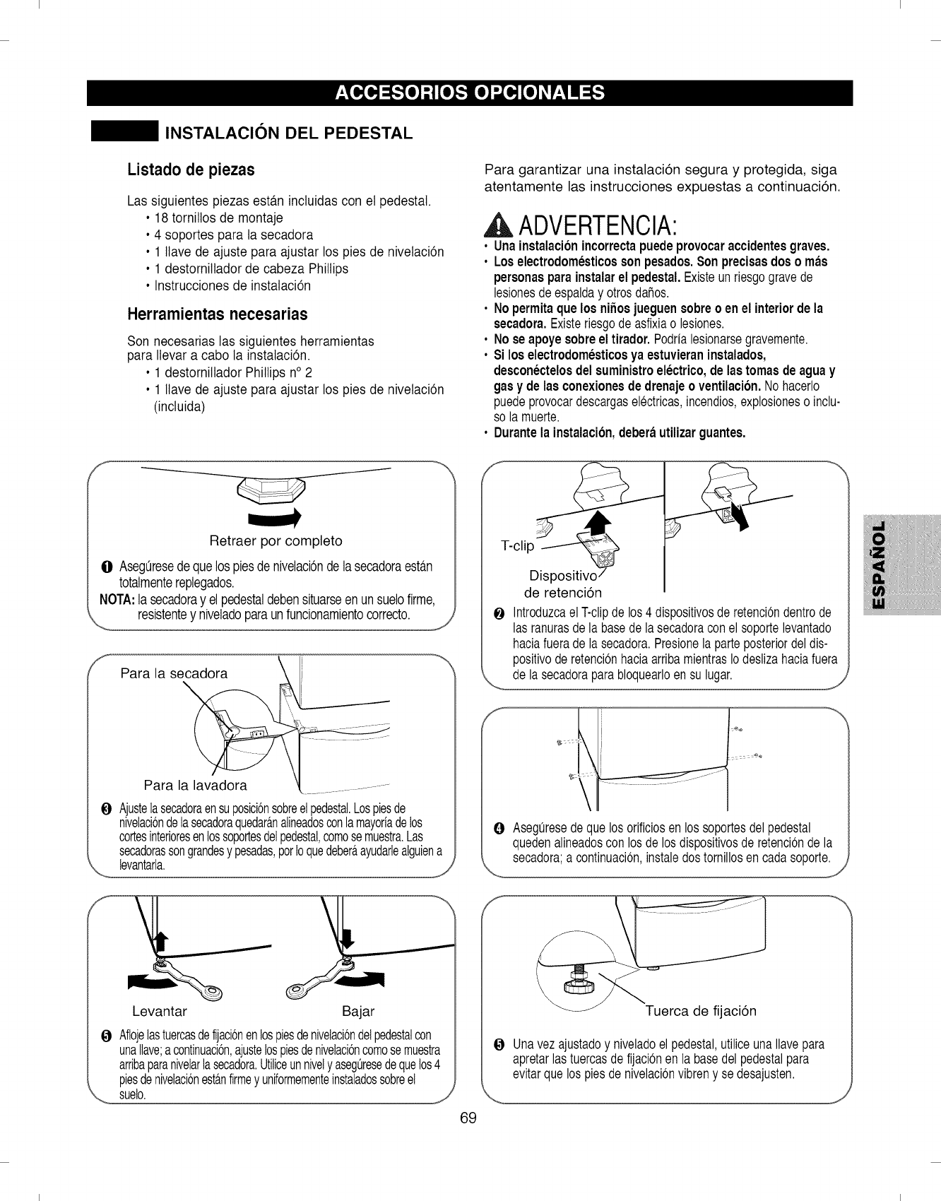
I I
INSTALACION DEL PEDESTAL
Listado de piezas
Las siguientes piezas estb.ninctuidas con et pedestal.
• 18 tornillos de montaje
• 4 soportes para la secadora
• 1 Ilave de ajuste para ajustar los pies de nivetaci6n
• 1 destorniltador de cabeza Phillips
• Instrucciones de instalaci6n
Herramientasnecesarias
Son necesarias las siguientes herramientas
para Ilevara cabo la instalaci6n.
• 1 destornillador Phillips n° 2
• 1 Ilave de ajuste para ajustar los pies de nivetaci6n
(inctuida)
Para garantizar una instalaci6n segura y protegida, siga
atentamente las instrucciones expuestas a continuaci6n.
A ADVERTENCIA'
• Unainstalacionincorrectapuedeprovocaraccidentesgraves.
• Loselectrodomesticossonpesados.Sonprecisasdoso mas
personasparainstalarel pedestal.Existeunriesgogravede
lesionesdeespalday otrosdahos.
•Nopermitaquelos nihosjueguensobreo en el interiorde la
secadora.Existeriesgode asfixiao lesiones.
• No seapoye sobreel tirador. Podrialesionarsegravemente.
• Si los electrodomesticosyaestuvieran instalados,
desconectelosdel suministroelectrico, de las tomas de aguay
gasy de las conexionesde drenajeoventilacion. Nohacerlo
puedeprovocardescargaselectricas,incendios,explosioneso inclu-
so la muerte.
•Durantela instalacion,deberautilizar guantes.
Retraer por completo
O AsegQresedequelos piesde nivelaci0ndelasecadoraesta.n
totalmentereplegados.
NOTA:la secadoray elpedestaldebensituarseenunsuelofirme,
resistentey niveladoparaunfuncionamientocorrecto.
Para la se_
Para la lavadora
OAjustelasecadoraensuposici6nsobreelpedestal.Lospiesde
nivelacbndelasecadoraquedara.nalineadosconlamayoriadelos
cortesinterioresenlossoportesdelpedestal,comosemuestra.Las
secadorassongrandesy pesadas,porIoquedebera,ayudarlealguiena
levantarla.
Levantar Bajar
J
0Aflojelastuercasdefijaci6nenlospiesdenivelaci6ndelpedestalcon
unaliave;acontinuaci6n,ajustelospiesdenivelaci6ncomosemuestra
arribaparanivelarlasecadora.Utiliceunnively asegQresedequelos4
piesdenivelaci6nesta.nfirmey uniformementeinstaladossobreel
suelo.
69
T-clip
Dispositivo
de retenci6n
O Introduzcael T-clipde los4 dispositivosde retenciondentrode
lasranurasdela basede lasecadoraconel soportelevantado
haciafueradela secadora.Presionelaparteposteriordeldis-
positivode retencionhaciaarribamientrasio deslizahaciafuera
de la secadoraparabloquearloensu lugar.
OAseguresedeque losorificiosenlos soportesdelpedestal
quedenalineadoscon losde losdispositivosde retenciondela
secadora;a continuacion,instaledostornillosen cadasoporte.
J
_Tuerca de fijaci6n
OUnavez ajustadoy niveladoel pedestal,utiliceunaIlavepara
apretarlas tuercasdefijacionen la basedelpedestalpara
evitarque lospiesde nivelacionvibreny se desajusten.
I I
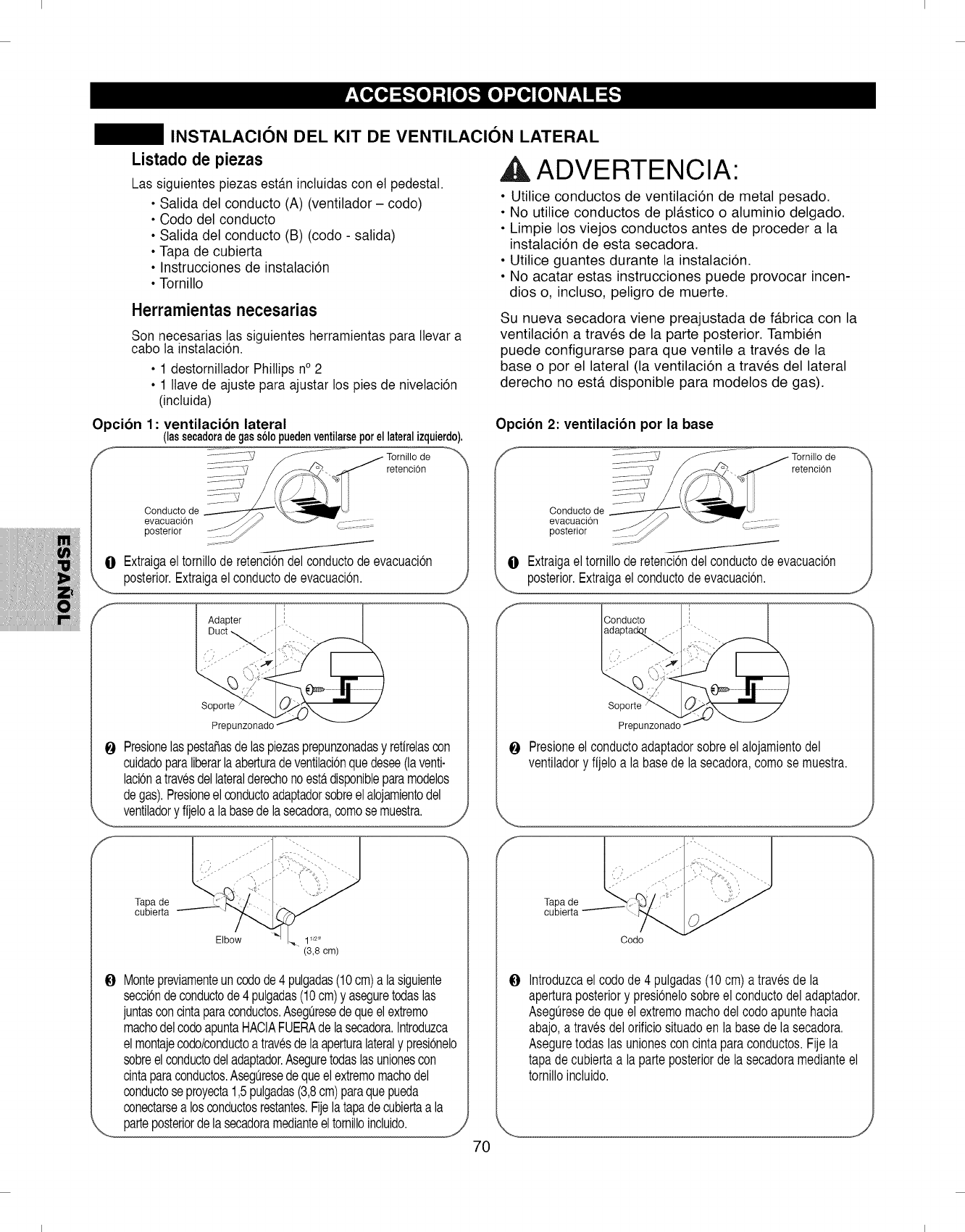
I I
INSTALACION DEL KIT DE VENTILACION LATERAL
Listado de piezas
Las siguientes piezas est_.ninctuidas con et pedestal.
Salida del conducto (A) (ventilador - code)
Code del conducto
Salida del conducto (B) (code - salida)
Tapa de cubierta
Instrucciones de instalaci6n
Tornillo
Herramientasnecesarias
Son necesarias las siguientes herramientas para Ilevar a
cabo la instalaci6n.
•1 destornillador Phillips n° 2
• 1 llave de ajuste para ajustar los pies de nivetaci6n
(inctuida)
Opcibn 1: ventilacibn lateral
(lassecadoradegass61opuedenventilarseporellateralizquierdo).
retencion
Conducto de
evacuaci6n
posterior
O Extraigaeltornillode retenciondelconductodeevacuacion
,_ posterior.Extraigael conductodeevacuacion.
) ........
Soporte
Pre[
0 Presionelaspestafiasdelaspiezasprepunzonadasy retirelascon
cuidadoparaliberarlaaberturadeventilacionquedesee(laventi-
lacionatravesdellateralderechonoesta.disponibleparamodelos
degas).Presioneel conductoadaptadorsobreelalojamientodel
ventiladoryfijeloa labasedelasecadora,comosemuestra.
Tapa de
cubierta
/
Elbow 1_2,,
(3,8 cm)
Montepreviamenteuncodode4 pulgadas(10cm)a lasiguiente
seccbndeconductode4 pulgadas(10cm)y aseguretodaslas
juntasconcintaparaconductos.Asegiresedequeelextreme
machodelcodeapuntaHACIAFUERAdelasecadora.Introduzca
elmontajecodo/conductoa travesdelaaperturalateraly presionelo
sobreelconductodeladaptador.Aseguretodaslasunionescon
cintaparaconductos.Aseguresedequeelextremomachodel
conductoseproyecta1,5pulgadas(3,8cm)paraquepueda
conectarsea losconductosrestantes.Fijelatapadecubiertaa la
parteposteriordelasecadoramedianteeltornilloincluido.
,A ADVERTENCIA:
• Utilice conductos de ventilaci6n de metal pesado.
• No utilice conductos de pl#.stico o aluminio delgado.
• Limpie los viejos conductos antes de proceder a la
instalaci6n de esta secadora.
• Utilice guantes durante la instalaci6n.
• No acatar estas instrucciones puede provocar incen-
dios o, incluso, peligro de muerte.
Su nueva secadora viene preajustada de f#.brica con la
ventilaci6n a traves de la parte posterior. Tambien
puede configurarse para que ventile a traves de la
base o por el lateral (la ventilaci6n a traves del lateral
derecho no est#. disponible para modelos de gas).
Opcion 2: ventilacion per la base
retenciOn
0Extraigaeltornilloderetencbndel conductode evacuacbn
posterior.Extraigaelconductodeevacuacbn. ,J
/
0
Soporte
Pre[
Presioneel conductoadaptadorsobreelalojamientodel
ventiladory fijeloa la basede la secadora,comose muestra.
Tapa de
cubierta
Codo
0Introduzcael codode 4 pulgadas(10cm)atravesde la
aperturaposteriory presionelosobreel conductodeladaptador.
Aseguresedequeel extremomachodel codeapuntehacia
abajo,atravesdelorificiosituadoen la basede lasecadora.
Aseguretodaslas unionesconcintaparaconductos.Fijela
tapade cubiertaa laparteposteriorde lasecadoramedianteel
tornilloincluido.
7O
I I
I I
Garantia limitada de un a_o
Si, tras ser instalado, operado y mantenido segdn todas las instrucciones incluidas con el producto, este
electrodomestico sufriera averias debidas a defectos de material y mano de obra, dentro del periodo de un
aho desde la fecha de compra, Ilame al 1-800-4-MY-HOME _'_para su reparacibn gratuita.
Si este electrodomestico fuera utilizado con fines distintos a los domesticos, esta garantia sblo seria aplic-
able durante 90 dias desde la fecha de compra.
Esta garantia cubre dnicamente los defectos de material y mano de obra. Sears NO cubrird:
OElementos consumibles que pueden gastarse debido al uso normal, incluyendo de forma enunciativa pero
no limitativa, los filtros, correas, bombillas y bolsas de la unidad.
O Un tecnico de servicio para mostrar al usuario la instalaci6n, funcionamiento o mantenimiento correctos del
producto.
O Un tecnico de servicio para realizar labores de limpieza o mantenimiento del producto.
O Da_os o averias en caso de no acatar todas las instrucciones de instalaci6n, funcionamiento o manten-
imiento incluidas con el producto.
O Da_os o averias en caso de accidente, abuso, uso inadecuado o uso con prop6sitos distintos a los fines
para los que fue dise_ado.
O Da_os o averias en caso de utilizar detergentes, limpiadores, sustancias quimicas o utensilios distintos a
los recomendados en las instrucciones incluidas con el producto.
O Da_os o averias en las piezas o sistemas provocados por modificaciones del producto no autorizadas.
Cldusula de exencibn de responsabilidad o garantias implicitas; limitacibn de recursos
El Qnico y exclusivo recurso del cliente bajo esta garantia limitada ser#. la reparaci6n del producto como se ha
mencionado.Las garantias implicitas, incluyendo garantias de comerciabilidad o idoneidad para un fin concreto,
est#.s limitadas a un aSo o el periodo de tiempo m#.s reducido permitido por la ley. Sears no ser#. responsable de
los daSos incidentales o derivados.
Ciertos estados y provincias no permiten exclusiones o limitaciones de daSos incidentales o derivados, o limita-
ciones en relaci6n a la duraci6n de las garantias implicitas de comerciabilidad o idoneidad, de tal forma que estas
limitaciones o excepciones pueden no ser pertinentes para usted.
Esta garanfia ser#. aplicable Qnicamente mientras este electrodomestico sea utilizado dentro de los Estados
Unidos o Canad#..
Esta garantia le otorga unos derechos legales especificos, e incluso puede conferirle otros derechos, distintos
dependiendo del estado en que se encuentre.
Sears, Roebuck and Co., Hoffman Estates, IL 60179
Sears Canada Inc., Toronto, Ontario, Canada M5B 2B8
71
I I

I I
P/No. • 3828EL3004V
I I
