Kenmore 867763792 User Manual GAS FIRED SECTIONAL FURNACE Manuals And Guides 99010398
KENMORE Furnace/Heater, Gas Manual 99010398 KENMORE Furnace/Heater, Gas Owner's Manual, KENMORE Furnace/Heater, Gas installation guides
User Manual: Kenmore 867763792 867763792 KENMORE GAS- FIRED SECTIONAL FURNACE - Manuals and Guides View the owners manual for your KENMORE GAS- FIRED SECTIONAL FURNACE #867763792. Home:Heating & Cooling Parts:Kenmore Parts:Kenmore GAS- FIRED SECTIONAL FURNACE Manual
Open the PDF directly: View PDF ![]() .
.
Page Count: 30
Sears owners manual
N[OOiLNOS,
867.76391
867,76398
867.77387
867,77388
867.77389
867_63792
867.763822
867.763832
867.76384Z
867.763852
867,773860
HOW TOORDER
REPAIR PARTS
SEARS SERVICE
IS AT YOUR SERVIa
WHEREVER YOU LIVE
OR MOVE IN
TNE U, S, d,
The ModelNumberwill befoundonthe RatingPlate locatedonthe
FrontDivisionPanel.AJwaysmentionthe ModelNtonber,vhen re-
questingserviceor repa)rpartsfor yourSearsFurnace.
All partslisted hereinmay be orderedthrough_ARS, I_OEBU(_
ANDCO.Whenoderingpartsbymail,selliqg priceswill befamished
on requestor p_rtswill be shippedat prevailingpricesendyouwill
be billedaccordin_y.
WH_ ORDERINGREPAIRPARTS.ALWAYSGiVE THE FGtLOWING
INFORMATIONASSHOWNIN THISLIST.
1. _ PARTNUMBER
7_The PARTDESCRIPTION
3. The MODELNUMB_
4. The NAMEof ITEM. GasFurraec
YourSears merch_ldisetakeson addedvaluewhenyou lsc_ _r
_q
that Searshas over 2,000 ServiceUnitsthroughoutthe count_.
Eachhasfullyequippedtrucksandis staffed bySe_ai(ed, pro-
fessionaltechniciansusingSearsapprovedpartsandIne_KIs.
LZ9"d LZ/LZd EIe-.L _EEBBYZ_iL9+ .Ld_ H_y_I$_J ,,i_l-iOJ'l lUCrE:80 66-SL-uer
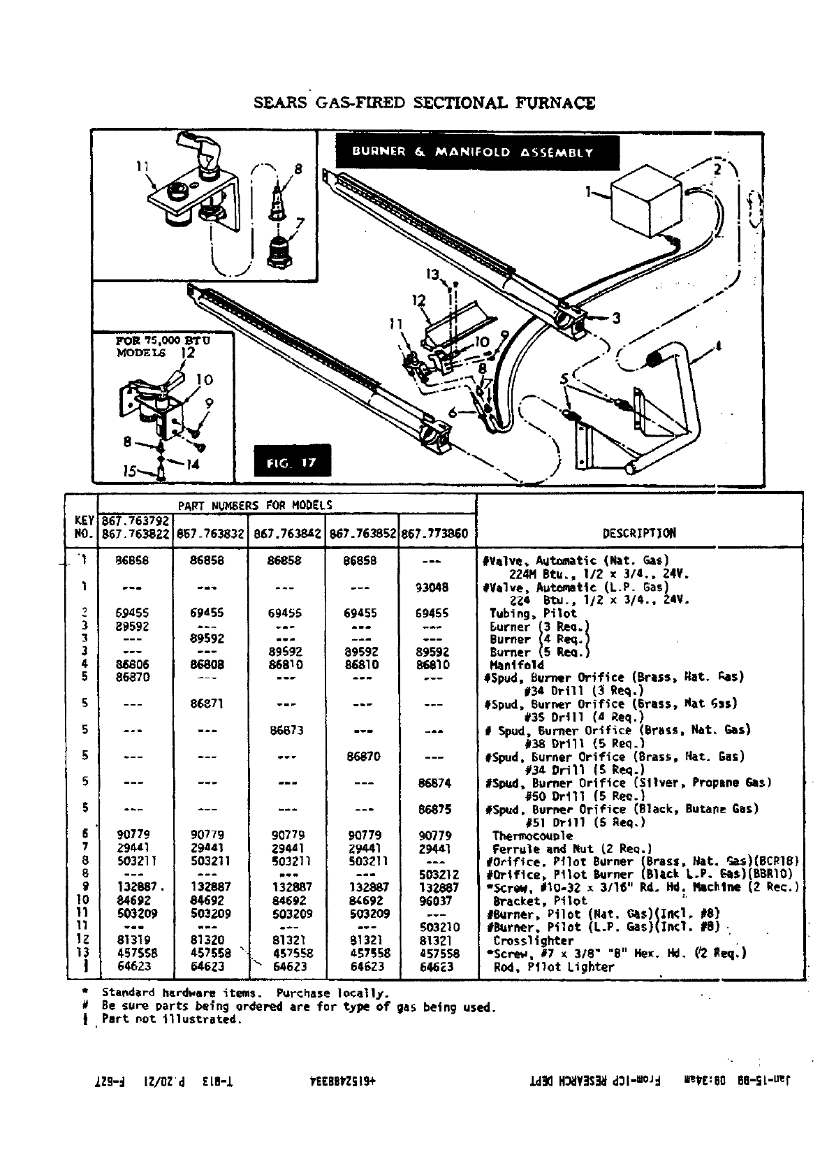
SEARS' GAS-KIR_.D SECTIONAL Fu*RNAC_
KEY
riO.
"1
Z
3
3
3
€
5
6
7
8
8
9
10
11
11
lZ
667.763792
867,763822
86856
69455
e959Z
B6806
86870
90779
29441
503211
132887.
8469Z
S03Z09
mmm
61319
45756E
64623
PART NUMBERS FOR HODELS
867_76383_
86858
6gdS5
69692
86808
86871
90779
zga41
503211
132887
84692
503209
mm_
813Z0
457568 "
646Z3
I
867. 7638421867.76385_
86858 86868
69455 69455
89592 89692
86810 86810
86873 ---
--- 86870
90779 90779
29441 Z9441
S03211 503211
132887 13Z887
64692 1_69Z
503209 S03ZO9
81321 81321
457566 _7556
646Z3 646Z3
;67.773_0
69455
8959g
86810
8_74
86875
9O779
29441
503212
137887
96037
_03210
81321
_57556
64623
DESCRIPTIOti
#Valve, Autumtt¢ (Nat, Gas)
224M Btu., 112 x 3/4., Z4V.
#Valve, Automatic (L-P- Gas)
2_4 8tu., I/Z x 3/4., Z4V.
Tubing, Pilot
Burne_
Burner
Haatfoid
#Spud, Burner Orifice (arias, Eat. _IIS)
#34 Ortll (_ Req.)
#Spud, Burner Orifice (Brass, Nat GaS)
@36 Oft11 (d Req.)
# Spud, Burner Orifice (Brats, fiat. _S)
#38 Or111 (5 Req.)
#Spud. Burner Orifice (Brass, ,Nat.Eas)
#34 Drill (S Req.)
i#Sl_l, Burner OrifiCe (Sliver, Prnpsne Gas)
#50Drlll (5 e_.)
#Spud, Burner Orifice (Black, Butane Gas)
#SI Drill (S geq.)
Thermocouple
Ferrule and Nut (2 ReQ.)
#Orifice. P_lot Burner (Brass, Nat, _s)(BCR18}
#Orifice, Pilot Burner (Black L.P. _S)(88R10)
"SCreW, €1O-3g x 3116" Rd. Hd. I_lc_tne (Z ke¢.)
Bracket, Pilot
#Burner, Pilot (Nat. Gas)(I_l. #8)
#Burner, Pilot (L.P. Gas)(In¢l, #8).
Crnssltghter
*Screw, _7 x 318" "g" He_. Fkl. (_ Req_)
Rod, Pilot Lighter
Standard hardware items. Purchase locally.
Be sure parts being ordered are for t_pe of gas being used.
J ,Part not illustrated.
ZZ9-d LZ/OZd [LB-I _EEBSkZSlg+ ld_ H_V]S_J _31"BOJd =ekE:60 88-SL-Uer
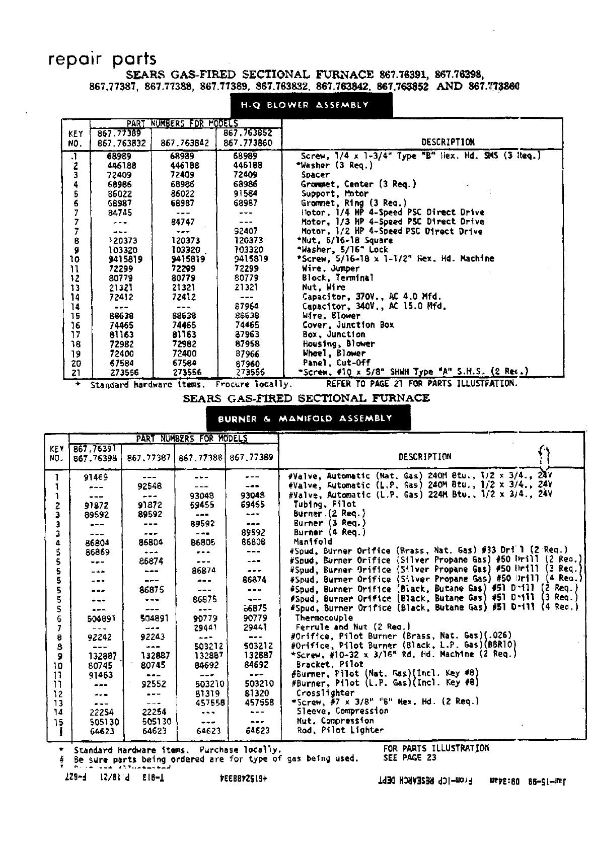
repair parts
SF.JkRS GAS-FIRED SECTIONAL FU_ACE 867.76391, 867.76398,
867.77387, 867.77388 867.77389, 867.763832. 867.763842. 867.763852 AND 867.7_386_
KEY 867.77369 B67.763852
NO. 867.763832 867.763842 867.773860
:l 68989 68989 68989
z446188 446188 446188
3 72409 72409 72409
468986 68986 68986
586022 86022 91584
6 68987 68987 68987
7 _,7_5 ......
7--- 84747 ---
7...... 92407
8120373 120373 120373
9 103320 103320 .103320
10 9415819 9415819 9418819
II ?2299 72219 72299
1Z 80779 80779 80779
13 213Zl 21321 21321
14 72412 72412 ---
14 ...... 67964
15 88038 88638 88638
16 74465 74465 74465
17 81163 81163 87963
18 7Z98Z 72982 87958
19 7Z400 72400 87966
20 67584 67584 67960
21 273556 273566. 273656
*Standard hardware items, r_ocure 1ocally,
SEAI%S GAS-FIRED
DESCRIPTION
Screw, 1/4 x1-3/4" Type "8" lies. Hd. _AS (3 ileq,)
*Wesher (3 Req.)
Seater
Grit, Center {3 Req.)
Support, P_tor
Grommet, Ring (3 Red.)
]lotor, 1/4 HP 4-Speed PSC Direct Drive
Motor, 1/3 HP 4-Speed PSC Direct Drive
Motor, 1/Z HP 4-Speed PSC 0trect Orlve
*Nut, 5/16-18 Square
*Washer, 5/16" Lock
"Screw, 5/16-18 x1-1/2" Kex. Hd. Nachtne
Wire. Jumper
Block, Temtnel
Nut, WiPe
Capacitor, 370V., AC 4.0 Mfd.
Cepacitor, 340V., AC 15.0 Hfd.
W_re, Blower
Cover. Junction Box
Box, Ounctlon
Housing, Blower
_heel, Blower
Panel, Cut-Off
"Screw #10 xB/8" SHWH] "A" $.H.S.
REFER TO PAGE 21 FOR PARTS ILLUSTPATION.
SECTIONAL FURNACE
PUNBER$ 0ODELS _'_'_
KEY 867.76391
NO. !B67.76398 867.77387 867.77388 667.77389
l
1
1
Z
3
3
3
5
5
5
6
5
5
5
5
7
8
8
9
10
11
ll
12
13
!4
15
I
91469
91872
8969Z
8680a
86869
504891
92242
132887
80745
91463
22254
505130
6_.623
.--m
92548
91872
89592
93048
69455
89592
93048
69465
89592
86804
86874
86876
S0_891
DESCRIPTION _
#Valve, Automatic (Nat. G_S) 240H Btu., lJ2 x 3/4., Z_/V
#Valve, Autometio (L,P. Gas) ZdOM BtU., I/2 x 314., Z4V
#Valve, Automatic (L.P. Gas) 224H Btu., 11'2 x 3j4., 2_,V
Tub1ng, Pilot
BUrner. (Z Req. )
Burner 13 Req.)
Burlier Req.)
86806
86874
86B75
90779
86608
86874
%6875
90779
_aliifold
#Seud_ Bgrner
#Soud, Burner
#Spud, Burner
#Spud, Burner
#Spud, Burner
#Spud, Burner
8Spud, Burner
Thermocouple
92243
132887
80745
92552
_2254
505130
64623
Orifice (Brass, Nat. gasl #33 Ortl (ZRea,}
Orifice {Silver Propane 6as) #60 !_rill (2 _eo.)
Orifice (Silver Propane Gas) #50 llrill (3 Req.1
Orifice (Silver Propane Gas) #SO llrill(4 Re_.)
Ortflc, _Bl,¢k, ButaneGas: #510"111 {! Req. I
Orifice (Black, Butane Gas #Sl 0"III ReD.
Orifice (Black, Butane 6as #51 0"111 Re€.)
294_1
503212
132857
84692
503210
81319
457558
6_623
29441
60321Z
132887
84692
503210
81320
457558
64623
Ferrule and Nut (2 RED.)
#Orifice, Pilot Burner (Brass, Nat, 6as)l.O261
#Orifice, PilOt Burner (Black, L.P. 6es)(BBRIO)
*Screw, #10-32 x 3/16" Rd. lid.Wachine (2 Req.)
Bracket. Ptlot
#Bur_er, Pilot _Net. rosS(Incl. F,ey #8)
#Burner, Pilot (L.P. Gas)(Incl. Key #8)
Crosslighter
*Screw, #7 x 3/8" "B" He1. Hd. (2 Req.)
Sleeve, CompressiOn
Nut, CompresSion
Rod, Pilot Lighter
tanderd hardWare items. Purchase locally.
Be sure parts being ordered ere for type of gas being used.
IZ9-_ lZ/8l_ EI8-1 VEEB81Z_19+
FORPARTS ILLUSTRATIO_I
SEE PAGE 23
ld_ H_JY]S_I dSl-=O_d merE:B0 B6-St-ue r
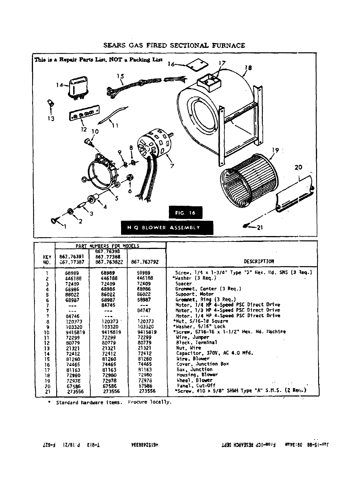
SEA_s GAS FIRED SECTIONAL FURNACE
15
12 10
\
6
7
19 _
2 o
KEY
NO.
I
1
2
3
4
5
6
7
7
?
8
9
10
11
12
13
14
15
16
17
_8
19
ZO
21
i
PART Nb_BERS FORM _ELS
667.76398
867.77388
867.7638ZZ 867,763792 DESCRIPTION
_7.76391
7_..67.77387
68969
4d6188
72409
68986
86022
68987
68989
4€6188
7Z409
68986
86022
68987
84745
84746
120373
103320
9415819
72299
80779
21321
72412
81260
7_a68
61163
72960
71_78
67586
273566
Standard hardware items.
120373"
103320
9418819
72299
60779
213Z1
72412
81260
74466
81163
72980
72978
67586
273556
56969
44_188
72403
68986
66022
65987
6a747
120373
I03320
9a15819
7Z299
80779
21321
72_12
61260
74465
81163
729_0
7297a
Screw, 1/4 x 1-3/4" Type "_" Hex. rid. SHS (3 _eq.)
*_asher (3 Req.)
Spacer
GrOmmet, Center (3 Peq.)
SuPPort, Motor
_r_t, Rin_ (3 _eq.)
Motor, 1/4 HP 4-Speed PSC Direct Orlve
Hotor, 113 HP 4-Speed PSC Direct Drive
Hot.or. 1/4 HP 4-Speed PSC Direct Drive
*Nut, 5/16-_8 Squar_-
"Washer, 5/16" Lock
"Screw, 6716-18 x 1-112" Hex. Hd. l_chlme
W(re, Jumper
Block, Terminal
Nut, _ire
Capacitor, 370V, AC 4.0 Nfd.
Wire, Blower
Cover, Junction Box
Box, Juhction
Housio9, 61ower
67586
Z73586
_heel, B1o_er
Fa_el, Cut-Off - "
*Screw, #lO x 5/8" SHWHType "A" S.11.S. (2 Rep_.)
Frocure locally.
LZ9-.I lZ/BLd EI8-1 _EEBB_Z_19+ ld_ H_VJ$_ dll-m°J:l =eVE:SO 66-S{-uei"
repair "harts
SEARS GAS-FIRED SECTIONAL FURNACE MODEL NOB, 867.7634)1,
867,76398,867.77387,867.77388,867.77389,867.763792,867.763822,867.7638_;2,
867.763842. 867.763852 AND 867.773860
NO. ,b7.?6383Z
1
g
3
4
5
6
7
8
9
10
11
11
12
13
14
15
16
]7
18
19
ZO
Zl
gZ
23
24
25
Z6
:7
28
29
30
31
3Z
33
34
35
36
36
37
3e
39
40
41
42
43
44
45
I
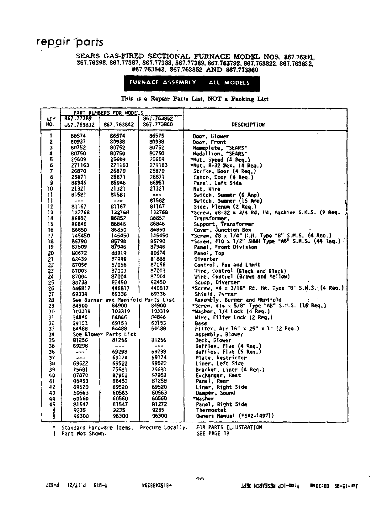
Th_ is a I_,pair Parts i_rt, NOT aPeeking List
PAR_ NU_EFS VOR _p£kS,
867.77389 867.763852
86574
8O937
8_752
80750
25609
;'71163
26870
28871
86946
ZI3Z1
81S81
81167
132768
86882
86646
86850
145450
85790
87509
80672
82439
87ose
87003
870¢4
_738
446817
69334
See Burner
84900
1O3319
848_6
691£3
6:_8
S_e 8lower
81256
69298
69522
75681
87870
86453
69520
60563
60560
81547
9235
96390
867.763842
86574
80938
80752
80750
25609
271163
26870
26871
86946
z1321
81581
.dm
81167
132768
868_2
86845
86850
148480
85790
87946
88319
87949
87056
87003
87004
82450
446817
69336
end Man(fold
8490O
103319
867.773860
85878
80938
8075g
80790
25609
271163
_5870
26871
86951
21321
81982
81167
13z768
86852
86846
66850
145450
85790
87946
80674
818,38
87056
87003
8700_
82450
•46817
69336
Parts List
84900
103319
DESCRIPTION
Door, Blower
Door, Front
N_eplete. "SEARS"
l_d_llioo, "SEARS"
*Nut, Speed (4 P.eq.)
",ut, 8-32 Hex. (4 Req.]
Str(ke, Door (4 Req.)
Catch, Door (€ I_m.)
Pamel, Left Side
NUt, Wtre
Switch, _r (6 Mp)
Svltch, _r (15 $_IP)
Side, )l_ (l Req.)
"Screw, 18-32 x 3/4 Rd. lid, Machine S._.S. (2 Req.
Tra.sfoMner,
Support, Transformer
Cover, Junction Box
*Screw, #8 x 1/4" ILIL TyPe "8" S._.S. (4 Req.)
*Screw. #10 x 112" SHMI Type "AS" S.M.S. (_ _eq.):
Panel. Front Division
Panel, Top
Olverter
Control, Fan and Limit
Wire, Control (Black and Black)
Wire, Control (Brown and Yellow)
Scoop. Oiverter S.N'.S."
"Screw, _4 x 3/16" _do IM. Tyne "8" . . (4 Re_.)
Shield, _,_-ner
Assembly. Burner and eenlfold
"Screw, _l_ x 5/8" Type "AR" S.r',S.(16_,)
*_asher, I/4 Lock (4 Re_.)
848=5 84846
69153 _9153
64488 64488
Parts List
81256 81256
69298 69298
6917a 69174
6992Z 595Z2
75681 75681
87952 87982
86453 81288
69520 695_0
60563 60563
60560 60560
81S47 81272
9235 9235
96300 96300
_tre, filter Lock (2 Req.)
Base
Filter, Air 16" x28" xI" (2 Reo.)
Assembly. 8loWer
Deck, _Io_m_r
Baffles, Flue (4 Req.)
Baffles, Flue (6 Req.)
Plate, Rostrictor
Liner. Left Side
Bracket, Liner (4 Req.)
Exchanger, _eat
Panel, Rear
Liner, Right Side
Damper. Sound
*washer
Panel. Right Side
Thermostat
Owners Manual (F642-14971)
*Standard Hardware Items. Procure Locally. FOR PARTS ILLUSTRATIOIW
IPart Not 5hawn. SEE PAGE 18
lZ8-_ IZ/lld £LE-Z VEEeB_ZSLg+ _H_YSS_I d3l-UlOJd UeEE:EO 611-EL-uzt
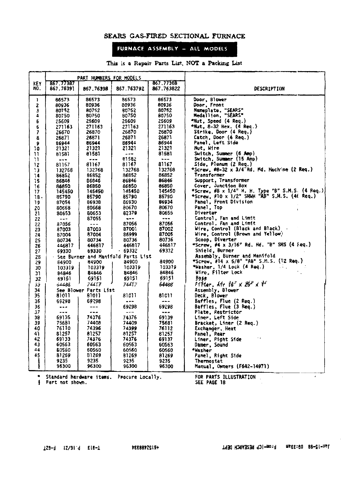
SEARS GAS-FIRED SECTIONAL FURNACE
This is =Repair Parts List, NOT a Pecking List
KEY
NO.
I
Z
3
4
5
6
7
8
9
lO
II
II
12
73
14
IS
15
17
18
19
zo
21
22
22
23
24
25
26
27
28
79
30
31
32
_r
34
35
36
36
37
38
39
40
41
:2
43
44
°i
857.7_387
867.78391
86573
80936
80752
80750
25609
271163
26670
26871
86944
21321
81581
..w
81167
132768
86852
86846
86850
145450
85790
87054
80668
80653
PART N_IBERS
867.76598
86873
80936
80752
80750
25509
271163
26870
26871
86944
21321
81581
81167
132768
86852
86846
86850
145450
85790
86938
80668
80653
87055
87056 ---
87003 87003
87004 87004
80734 80734
4_6817 446817
69330 69330 '
•See Burner and Manifold
84900 84900
FOR MODELS ,
867.763792
86573
80936
80752
80750
25608
271153
26870
26871
86944
_1321
8158_
81167
132768
86852
86846
66850
1a5650
85790
8593O
80670
82379
87056
87001
86999
80736
446817
69332
Parts Ltst
84900
857.77988
867.76382Z
86573
80936
80752
80750
a5609
271163
26870
26871
86944
21321
81581
81167
132768
86852
86846
86850
145450
85790
86934
80670
8O655
87056
87002
87005
80736
446817
69332
84900
DESCRIPTION
Door, Blower
Door, Front
N_plate, "SEARS"
Medallion, "8F_RS"
*Rut, Speed (4 Red.)
_NUt, 8-32 Hex. (4 Red,)
Strike, Ooor (4 Req.)
Catch, Door (4 Req.)
Panel, Left Side
Nut, W(re
S_ttch, Summer (6 Amp)
Switch, Sum_r (15 Amp)
Side, Plenum (2 Req.)
*Screw, #8-32 x3/4"Rd. Md. Fhch'Fne (Z Req.)
Transformer
Support, Transformer
Cover, Junction Box
*ScreW, #8 x 1/4" H, H. _ype "B" S,N.S, (4 Req,)
*Screw, #10 x 1/2" SHWH 'A8" S.R.S. (41 Req.)
Panel, Front Dlvlston
Panel, Top
Dfverter
Control, Fan and Limit
Control, Fen and Limft
Wire. Control (Black and Black)
Wire. Control (Brown and Yellow:_
Scoop, Oiverter
"Screw, #4 x 3/16" Rd, Hd. "B" SNS (4 Led,)
Shield, Burner
Assmbly, Burner end Manlfold
"Screw, 114 x5/8" "AB" S.tl.S. (lIZ Req.)
103319
8_8_6
See Blower
81011
69296
69135
75681
76110
81257
69133
60563
60560
81769
9_35
96300
103319
84_6
6_151
7_r7
Parts List
81011
69?98
74376
74408
74398
81257
74376
60563
60560
81269
9236
96300
103319
84846
€9151
7,_ZI'7
81011
J
69298
7¢376
7=408
74399
81257
74376
60563
60580
81269
9235
96300
103319
84846
81011
69Z_8
w.m
69139
75681
76112
81257
69137
60563
60560
81769
9239
96300
*Wisher, 1/4 Lock (4 Req,)
Wire, Filter Lock
Pf11_er.Xfr 116J' K_I' _ if,'
Assembly, 81ower
Deck, Blower
Baffles. Flue (2 Req.)
Baffles. Flue (3 Req.)
Plate, Restr_ctor
Liner, Left Side
Brlcket, Liner (2 Req.)
Exche_er, Heat
Panel, Rear
Liner, Right Side "
Damer, Sound
*Washer
Panel, Right Side
Thermostat
Manuel. Owners (F642-149719
Standard hardware itemS. Pnecure Locally.
Part not shown. FOR PIRTS ILLUSTRATION
SEE PAGE 18
ZZB-d IZ/gid £LB-I kEEBBtZSL9+ _2 H_V]S_ d3l-Um_d eeE£:80 66-SL-uer
t11
_n
T
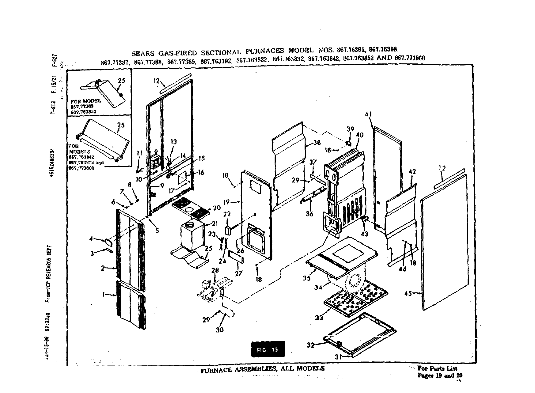
SEARS GAS-FLiED SECTIONAl. FuRNACeS MODEL NOS _6"L'/6391, 867.76,_98,
8_7.77387, 867.77388, 867.77_t9. 867.763792, ,_7_76_822. R67.763832, 8_7.763842,. 867.7_852 AND...867,'/'/3860
"f. ,_
I!
13
/
!
Low asetting u po6s_ble and sttll have it turn off
when furnace is cool.
(2) Fuse Blown or Wire Broken. Correct the
trouble.
(3.): Blower motor needs attention of a service
tee.k_cian.
NOISY BLOWER
(i) Housing Rattles.Tighten screws.
(2) Needs Lubrication.Lubricateper instruetian&
(3) Air FiltersDirty. Replaee them.
NOISY FLAMES
11) Excessive Gas Input. Probably due _o too high
agas pressure. Adjust gas regulator,
(2) Damagea orifice (i_ it whL_les). Replace
wih'_ new one.
SOOT OR CARBON IN BURNER OR COMBUS-
TION CHAMBER--SWEATING OF WALLS OR
WINDOWS
(i) Ir_.fficient Ventilation. Prov, de permanent
vent opening to outside,
(2) Smoke #pe or Flue Bl_.ked or Improperly
In._tane_ Check--and correct as required.
(3) Ventilating Fan Drawing Flue G_ Back
Down Flue pipe and Out o{ Diverter, Do not oper-
ate fan in vicinity of fm-n$ce, provide permanent
vent _ to oumide,
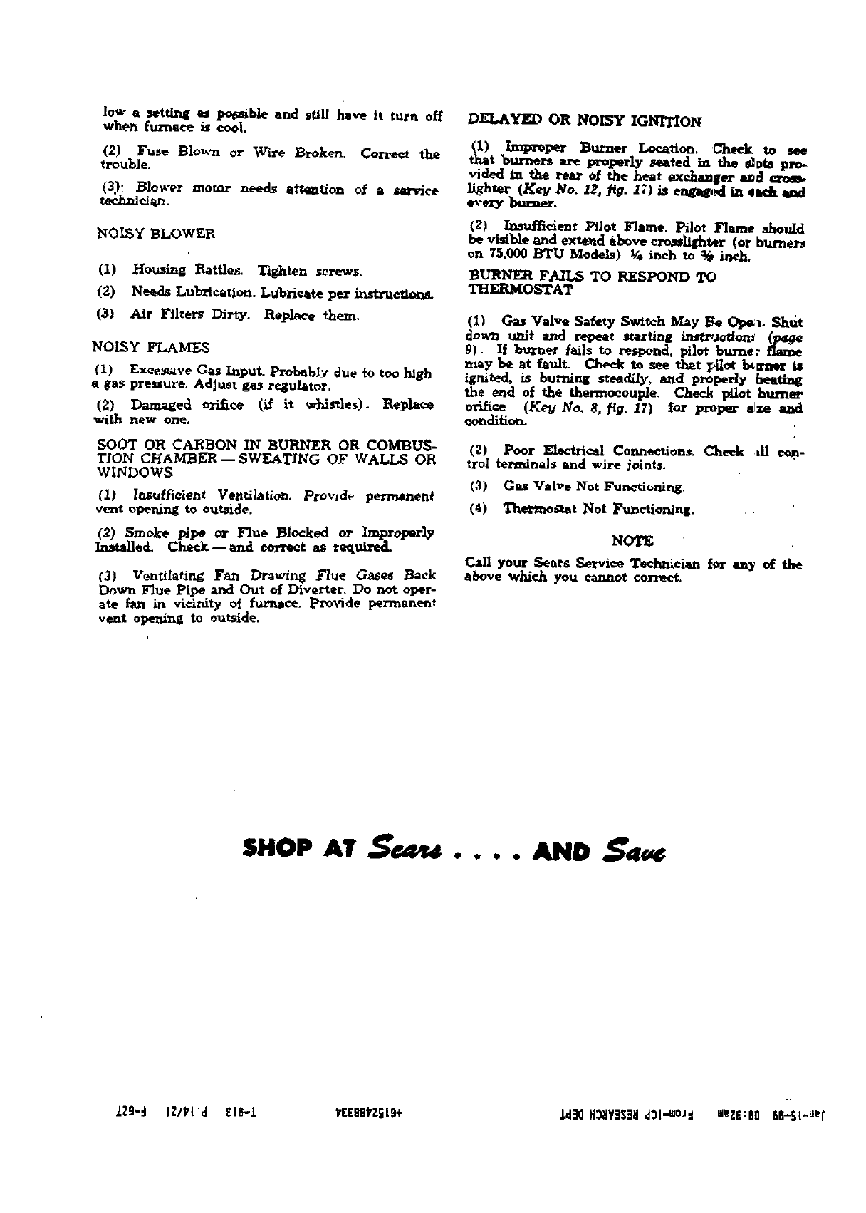
DELAYED OR NOISY IGNITION
ImprOl_r Briner Loe_tton. L-'_mekto see
tburners are properly seated in the _Dts pro-
vided in the rear of the heat exch_ler _
lighter (Key No. 12, .fig. 17) iS e_ in €#tt_b.
e_,-er/ burner.
(2) Inaufficient Pilot Flame. pilot Flme should
be visible and extend above cronligh_tr (or burners
on 75,000 BTU Models) V4 i.eh to _¢pinch.
_URNER FAILS TO RESPOND 'IX;,
THERMOSTAT
(1) Gas Valve Salty Switch May _e Ope,1- Shttt
_owta u_t and repeat starting L',J_JCtion_ (F4g¢
P). If bttrner fails to respol_d, pilot bume: flame
may be at fault. Cheek to see that l_*LIotbl_'l_r
ignited, is burning steedily, and properly heating
the end of the thermoeouple. Check pilot }_urner
orifice (KeN No. 8, _. 17) for proper _ze and
_onelltioD.
(2) Poor Zaectrlcal Conn_ions, Cheek :,ll c*m-
trol terminals _nd wire joint,€,
(3) Gas "Valve Not _h_Jnetioning.
(4) Thermostat Not Functioning.
NOTE
_11 your Sears Service Technician for any of the
above which you cannot correct.
SHOP AT AND
ZZg"d lZ/_l'd ZlS-/ kEE86_ZSLg+ _H_JY]S_Id3l_O_d _eZE:80 86-st-._r
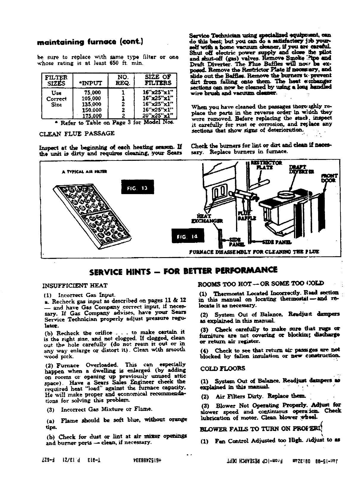
maintaining fumoce (€ont)
be sure to replace with same type fiker or one
whose rating is at least 650 ft rain,
s_T_ NO. SIZE OF
•INPUT REQ. FILT]_S
Use 75,000 116"x2F'x1"'
Corre¢_ 105,000 1 16"x25"xl"
Size 135.000 2 16"x25"x1"
150.000 2 16"x25"xl"
1TS,000 2 20"x25"xl"
" Refer to Table on Page 3Or Mode/l_os.
CL.EAN FLUE PASSAGE
_x_ a¢ the begin=d_ _eeeh heating seas_. If
, unit is dirty artd requires ele_ntr_, your _
do this beet; b_ Fou __o a _ |_b Y_.
self with a .bornevse_. Q1mn_r. tf _mamm_
S_ _ electric _ _ _ _ ._be
and_(_) valve. _ _molr_ **_q[maxl
Draft Dirtier. The Flue Baffles wln no_ rm ez-
_Remove _he _€_r l>b_ _nee_m'y, mxt
out l_e _P.eme_ the b_M_ k, 1_t.vmt
diz,t h.om _dting onzo them. "rn_ lmst ,__mm_
se_-tionscan now be cleaned by u=h=ga1o_ ]mmdlmd
wix._brush and vacuum €_a_e. :,_
When you have el_nod the pa_ages thoi_Ltghly re-
pla¢_ the parts in the rev_-_ order in. wl_=h they
were removed. More re_ the. stY, in_peet
it care_]Iy for _st o_ corrosion, and l_._ee any
_ee_to_ that show _of deterlomti_ , i".
Cheek the burner_ for lint or dirt aat_ clean tf nsees-
ss_y. _.ep]_ burners in furnace.
SERVICE HINTS - FOR BETTER PERFORMANCE
INSUFFICIENT HEAT
(I) ]nL_)l_re_t Gas [I1p_t.
a, 1_cheek gas input as described on pages 11 & 12
-- and have GaS Comi_nY correct input, if
sary. If Gas Company advises, have your
Service Technician proper|y adlust pressure regu-
lator.
(b) Recheck the orifice .,. to make _it
is the right size, :_r_€lnot clogged. If clogged, clean
out the hole _refully (do not ream it out or in
any way enlarge or distort it). Clean w_.th smooth
,rood pick.
(2) _ar_ace Overloaded, This can esp_ia]ly
happen when adwelli_ is erdarge_ (by adding
on rooms or opening up previo_ly unused attic
s_e). H_ve aS_rs Sales ._neer cheek
required heat "load against tht turnace eapactry.
He will make proper and economical recommenda-
tions for solving t_s problem.
(3) Incorrect Gas Mixture or Flame,
(a) Flame should be soft blue, without orange
til_.
(b) Cheek for dust or Unt at air _opemngs
and burner ports _clean, if necessary.
ROOMS TOO HOT--OR SOME TOO COLD
(1) Thecmo_t Located _- Rud section
in th_ mantu_ on locating thermost_it_l re-
locateit as _.
(2) System Ou_ of Balance. li_dj.a dampen
ss exp_ in this manual
(_) Cheek care_Uy to ,_e _fl..t rups e_
/umimr* are not _o_ or block_¢
(4) Cheek to see that return _d_ pa_ges are not
blocked by _lle_ insulation or new cmmructiea.
COLD FLOORS
(1) System Out o_ Ba]_tee. _ _ m
explained tu th_ manual . *
(2) Air Filters Dirty Replecethem.
(3) Blowe_ Not Operating Properly. iAd|ust for
slower speed and _.L_uous opera=_L Cheek
lubri_on of motor. Clean blower .w_£
BLOWER FAILSTO TURN ON PI40_
\
(I) Fan Control Adjusted too lli_h. _Uljust to u
• .
LZ9-d i_/[l'd ElB-L _EEBek2_Lg+ ld_ H_IY]$_I d3l-1O_d umZE:60 ea-st-uer
I
-%.
T
b'.-
_ro
-I-
.a
CONNECT FIELD
HOT W_E TO
BLACK PIGTAIL
WIRE
GROUND
:_ TO COMMON TER_AL "E"
....... _ TO COOLING TER_DNAL "¥"
o
WIRE CODE
H_B VOLT. FIELD WI_E
H_GH _OLT. FACTORY W_tE
::== LOW VOLT. FIELD WIRE
.... LOW VOi.T. FACTORY WIRE
!
.--_ WIBE CIRO_O VER
CAPACITOR MOVE YELLOW WIRE TO
TERMTt_AL "R". "El/_ OR
"BK" TO INCRE,_E BLOWER
,.qPEBD FOR HEAl"raG.
WHITE
YELLOW
VTOLET
CONNECTED, )-- 4.--
NECT TO TER]t_AL INDICATED _q
TABLE PAGE 14 FORSUMMER
CONDITI_G.
BLOWER HOUSING
JUNCTION BOX
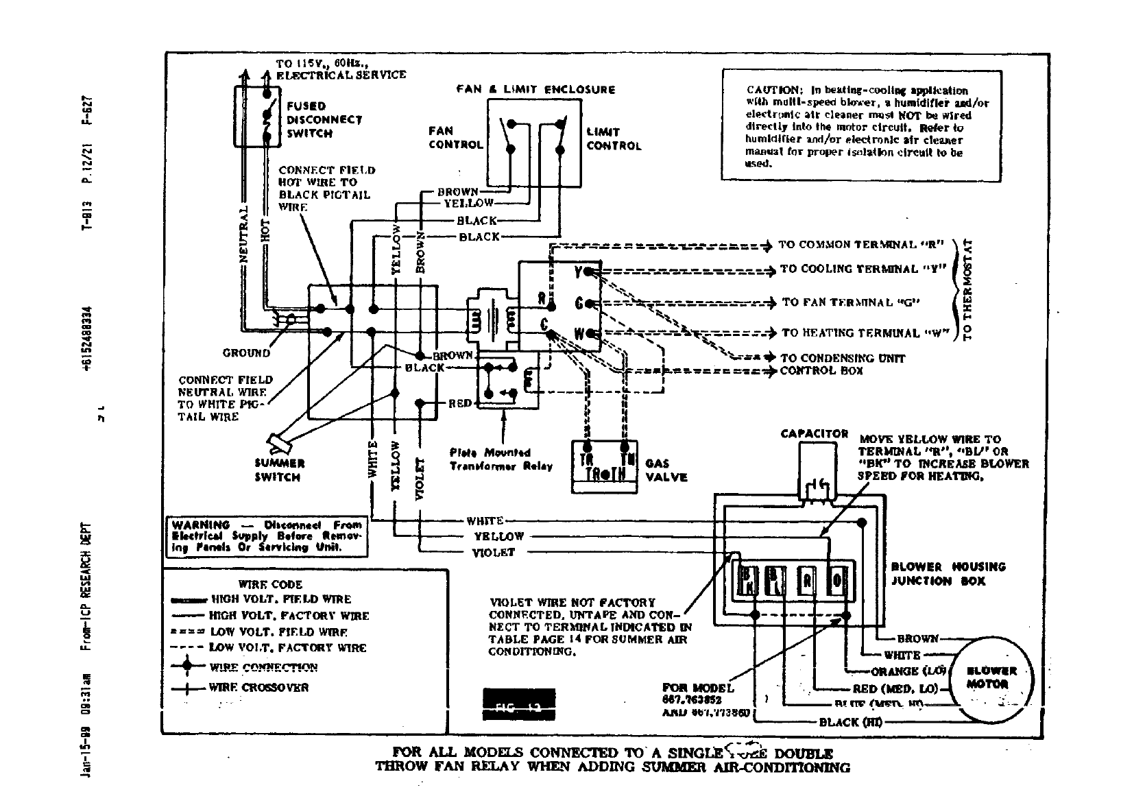
FOR ALL MODELS CONNECTED TOA SING£,E___ DOUB_
THROW FAN RELAY _ADDING SUMM]_ AIR-CONDITIONING
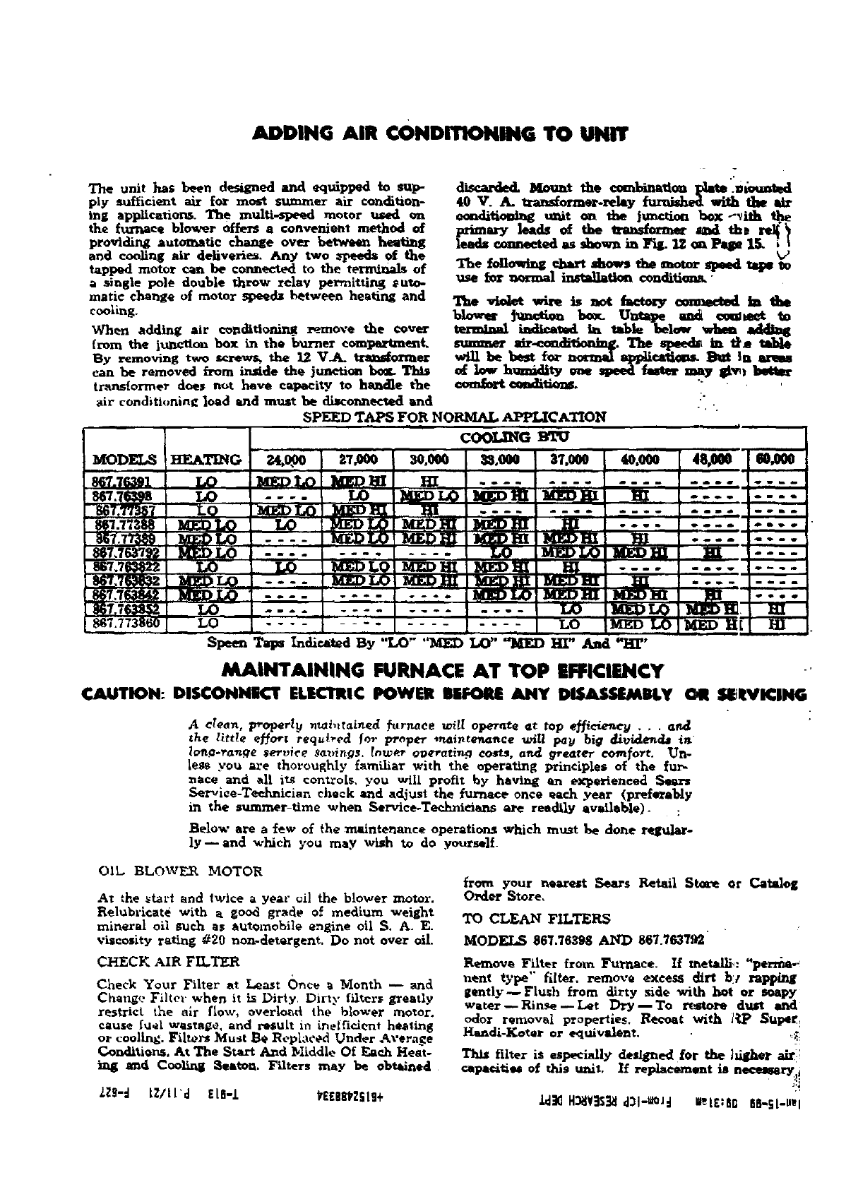
ADDING AIR €ONDITIONING TO UNiT
The unit has been designed and equipped to sup-
ply sufficient air for most summer air condition-
ing applications. Th e multi-speed motor used on
the furnace blower offers a convenient method o_
providing automatic change ove_ betwa¢_ heafi_g
and cooling air deliveries. Any two _peed_ of the
tapp_] motor can be connected to the terl_l_ls of
as_ngle POle double throw relay permittlng _uto-
mati¢ change of motor spee_ between heating and
cooling.
When adding air cQndttioning remove the €over
from the junction box in the burner compartment.
By removing two _the 12 VA_ _Pa_0_nl_r
can be removed from inside the jtmetion bog- This
trans[ormer does not have capacity to handle the
air conditioning load io_d must be di_ol_ectcd and
40 V. A. _-relay fumlshed with the air
eonditio_t_ unit on the Jm_on box--_ith
erimry leads of the _.anstom_ _ thD re_
leads connected as shown in Fi_ lZ oa l-age 1S. it
The f_llowing chart shows the motor spead taps _o
use for normal installation condttion_"
The vto_ w_ is _t factory connected lath.
blower Jmu_inn bow.. Unta_e and eemmet
termUad _t.d ta table hele_ whon adding
_air_. 'l'he .peed_ h, em tad_
be best for normal am_icatkm. _ _n arms
low hmnidity one _eed- _ may _bitter
__. --
SPEED TAPS FOR NORMAL. APPLICATION
C00L_G Wl"U
Speem Taps Indicated By "LO" "MED LO" "MED HI" And _[I"
MAINTAINING FURNACE AT TOP EFFICIENCY -'
tAtrlrlON: DI$CONINIIK'TEI.|CTItI¢ POWER SliFOI_ ANY I_IS_W.IE_UtI.YOII Sl_lt¥1_ll_
Aclean, Vroparlg _i,*rained furnace wi[! ope_xte et top e_cieno_ .. . and
the _tttle e_ort required for proper *neintencxnce u_f[! pay big _vi_em_ in
h:,Rg Y'a_e gert, ice .ee_)_rtg_. [n,_r ooerat_ng costs, a_ greGter com_ort. Urt-
|e_ you ere thoroughly _arn_liar with the operating Principlea of the fur-
nace and all i_ controls,you will profit by having an experienced Sears
Ser_ice-Tee_mician check and a_ust the _urnace once each year (preferably
in the summer-time when Service-Technicitms are readily available). :
l_elow are a few o_ the m&intenance operations which mu._t be done regt_lar-
ly _and which you may wish to do .yourself_
OIL BLOWF.R MOTOR
At the _t_rt and twice ayear oil the blower moWr.
Relubr_¢ate with a good grsde O_ medillm weig_'_
mineral oil such as automobile engine oil S. A. E.
ViSCosity rating #20 non.detergent. Do not over oil.
CHECK AIR FILTER
Check Your Filter at Least Once _Month _ and
Chauge Filter when it is Dirty. Dirty filtcr_ greatly
restrict the air flow, overload the blower me,or.
cause fuel wastage, and result in _ei'fidcnt hee|ing
or cooling. Fihors Must Be l_eplat',ed Under Average
Condhi_ns, At The Start And bliddle Of Each Heat-
_d Coo_ _eaton. Filters may be obtained
ZZg-d LZ/LLd £L8-1 kEE6812ft9+
from your n_arest Sears Retail StoLe Or Catalog
Order Store,
TO CLEAN FILTERS
MODELS 867.76_98 AND 867.763792
Remove Filter from Furnace. If metallic: "pertain--:
nent type" filer1 remove excesS dirt be rapping
_ently_ Flush from dirty side with hot or soapy
water_Hinse_Let _¢y_To re_to_,_ dttt"t and
odor removal properties. Re_tt with l_ S_per,
Handi-Kotar or ¢_uivalent. .'_i
Thts filter is especially des!Shed _or the higher air:i
capa_ti_ of this m_it, l_ replacement is ne¢_ur_ i
.Ld]MH_V:I$_I d31-m0Jd I_eLS:SG 88._L.USI
Now _t th_ tl_]_ostm for the desired _
room teml_rature. If the thermostat is |o_ted
where the airdrculatingin the room (and nothing
else) affects it-- and ifthe room in which itislo-
cated is "a_-r_e" for the dwdlin_ ,. . then the
temperature throughout the dwe|ih_$' wil] stay €_l-
smntly between this n_mraum setting and the few
degrees higher for which you have adjusted yomr
thermo._tat differentia}. _. however, e stroDg
blows at one i_.de of the dwelling (so that rooms on
th_s _ide are abnormMly colder), or ff your thermo-
stat _poorly located {so that its opemtios_ i_ [ov-
erned by "local" condi_t_ tnstead ot the avexage
dwelling_mpexature) ...then you willhave to
alter the sett_M8 xmtil you fred one at which the
average dwellir_g _mpera_re is comfortable.
Some fuel can be saved by lowering the thermostat
sefting a£ew de[_rees at night. But do not se_ it
more than 5° to 8" lower (depending upon ',:he
sevez_.ty of the weather), or you will lose the econ-
omy by makin_ your lurnaee run too long in the
morning to reheat your d'w_ to the desired day-
time te_r_tttre.
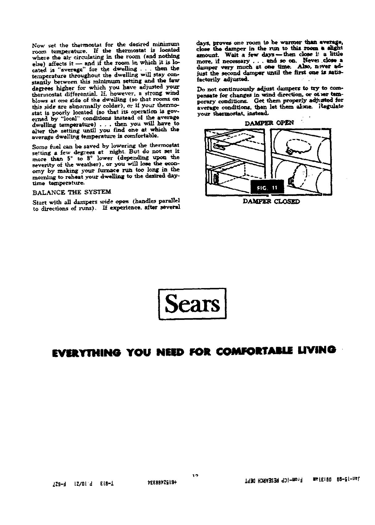
BALANCE THE SYSTEM
Start with all dampers w/de open (handles parallel
to directions <ff runs}, /_ etperienee, _ft_r _m_reral
da3nt,pl_)vos one room to be wanne_ then aves_q_e,
close the damper in the ___to this room a _t
_mount. Wait ale_ days then elme i_ a _ttle
more, if neces_W ..,_i _ o_. Neve_ .r.l_m a
damper very much at one time. Also, n,.-ver ad-
just the #ecomt _mper tmtiI the fu_t _ h, _tis-
mctor dmmd.
Do not em_tinuot,.dyadj-u_darnperato _to eom-
pemmW for changes in wind direc_on, or ot_er ben-
porary condlUon_ Get them properly ad_xmed
average €onditi_. then let them al,m_- ]Regulate
your d_ostat, imtea4,
D_ OPEN
D_ CLOSED
ii
lSearsl
EVEIUIrTHING YOU NEED FOR lrlrABI, E IRVING
2zg-d LZ/OId EIS-L _tE8skZilS+ Ld_ H_¥_S_l d31--_d m1£:80 SS-iL-U_f
check-adjust (cont.)
IXAMPLE
PEGT" und it look 54 _cmds fur one revolutlem.
In the "Input _" €olumn o# the ruble ep_site "$4 #
It_ the "_e." column you find the figure "67".
As yovr$ Is u _O [girt die|. you muit|ply this
fisvre by 2-- to urrlvu st "1_4." Yc_r _s €_n-
piny bus hdd yov fll_ the STU r_llw of your
ires is 1000. Multiplying 134 x1,900 plvw y_
134,0GO--the actual BTU/HIt ir_lut to your
he4tln9 unit. Your vnlt is rM_l for 1_;,40Q
BTU/HR input, aqd 134000 IS ngt more th_
135,000_sO the "e_tvel" input tQ your ul_lt is
within the _Dquirsd llmltL
If the burner orifices hnmished u-i_h your unit do
not give the proper input, check wi_ your local Gas
•Company for the proper orifice size,
PItIMARY AIR ADJUSTMEI'_
Air shuLter$ are no_ norm_ly supplied _the burn-
era are d_gned to in.'_pirate correct amoun_ of pr_-
mary oh" on either natural or LP gas.
CONTROLS
Limit controls are preset at factory and should not
be a6justed_
ADJUST AIR FLOW
The _rnace is equipped with adireet_drive blow-
er with multi-speed motor. If air lqow adjust_eDt
is necessary, it Ls aeeompIif,_ed _- changing motor
speed- The u_$ is factory wired to give lowest
blower speed on the heating cycle and it will not
often be necessary to change this heating speed.
If. however, it i_ desired (o decre_se the outle! oir
temperature from the hn'noee, (increase blower
speed) it is accomplished In the foll_ mann_-:
I, Shut off power to _t_
2. Remove cover from junction box on blower
housing.
3. Remove yellow _t_re (lead from I'_ati_ cycle
fan control) from Lo-Speed terminal a_d push onto
desired higher speed te_ninaL
NOTE: The white ,v|re is _.he common lead a_l is
not _o be moved when ch_i_g blower speed,
The violet wire is not factory _but is
tape_ off in the blower junction box, Un_ape and
connect to _rminal indicated in table _P_e 14
when adding summ_ air-€onditiordn_,
4. Reverse steps I and 2a_ve.
Adjustment should be made to run _be blower
to deliver the lowest pra€ticable sir flow. This
is de,re'hie bemuse, first, it me_u_ less current
consumption, a_ second, l_ noticeable draft at
the warm eir o_tlet_. The blower should deliver
the amount of air
rise _ro_tli[h the which w[/l produce a temperature
_mit of between 45 ° to 75 _for
Models 86_._86.76398 and 867.763792 and between 70°
and 1_0_tot Mod_ 86_._391,g$'/.77_87, _67.77_gg,
867,773_9, 867.763_,_, 867.76_832, 867.763842, 8G7..
:!_g_tE_ _md. S6_.773860.
).:'9-_ t;!/BO'd rl6-1 kcE98PZSI9+
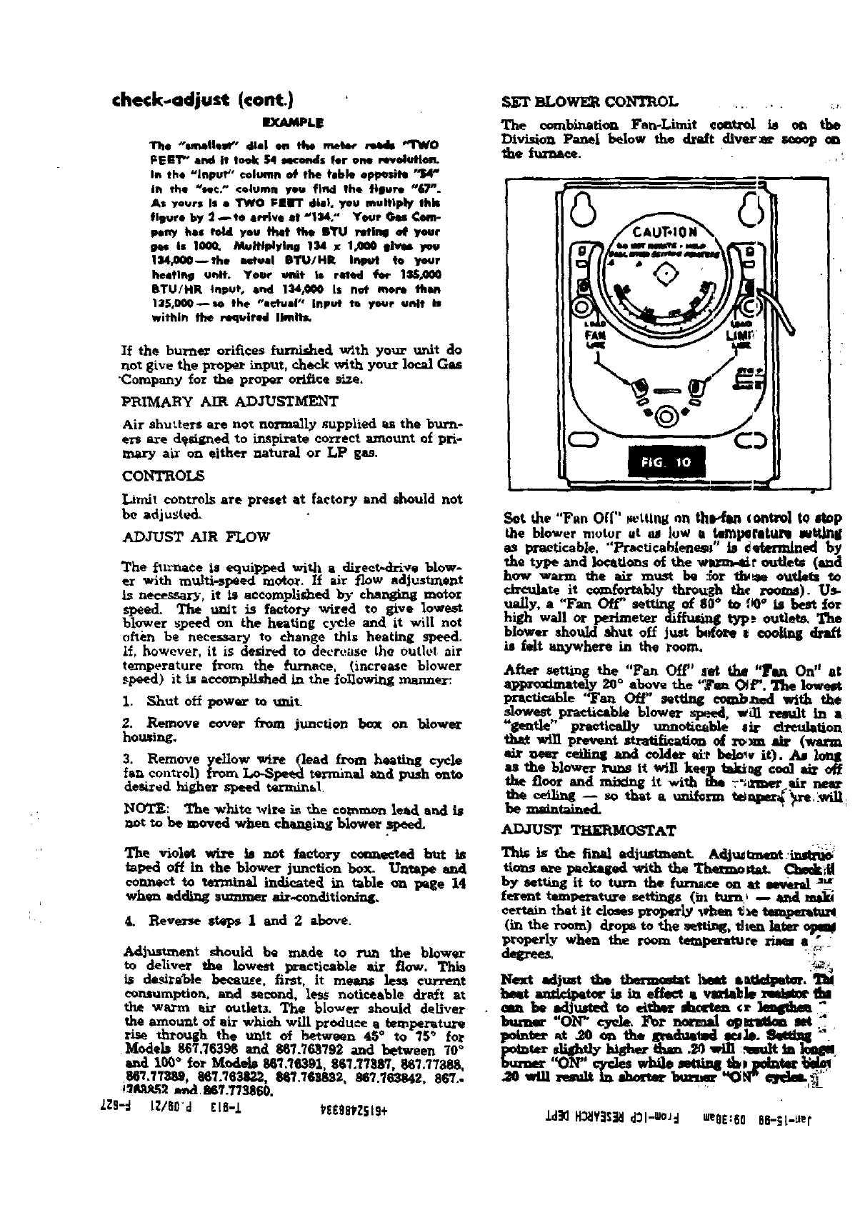
SETBLOWER CONTROL .......
The combination Fan-Limit eont:_ is on the
Division Panel below the dre/t diver_ seoop on
the im'na_. ,:
|'
Sot the "F_n Off" Netting on th_ (ontro| to stop
the blower motor at _low ta leml_flKul_ mtt]n_
as practicable. "'Practicableness" is _mlldned by
the type and locations o_ the w_lk.4dt" ou_dets (&l_d
how warm the air must be :_or t_e outlets to
circulate it _b]y throttgh the roo_n_). Us-
ua!ly, a "Fan Off' setting of 8_o to 00° is best tot
high wall or perimeter _ffusi_ type outle_ The
blower should shut off Jt_t _0_ I €O0_ d_'l.tr"t
is felt _,ywhere in the room.
After _the "F_ Off" _t the 'T_ On" at
Xlq_roxln_tely 20 °above the '7"_ OJF. The lowest
pracUCa_e 'Tan Off" set_ comb_-d with the
_?w_t,,practicabie blower _._d, w_ re_lt in a
gentle practically unnoticable #it _reuleUon
thst win prevent stratification, of r_m sir (warm
sir _ceilL_ and colder __'r l:,cl_,, iO. A_ long
as the blower runs it win ke_p takt_g coo) sir off
the floor and mixing it with tim _'_mer _r ne_
ADJUST THERMOSTAT
TI_ is the tinal ediustmant _lju_un_t.inm_
ttons s_e pedcaged with the The_mo_ Checkoff
by setting it to turn the tur_*ce on st asverd :'_
ferant temperature s_ttiz_s (be turn, -- aridm_
co_dn that it closes prop_y wh_m _e tompemtur4
(ir_ the room) drops to the _g. 'Ir]te_later €_
p_perlv when the room te_perxture _e,_ :
Next edjmt th_ tbermo_t hint s_.'T_
beat ._t_tor is _ _ av._tle m._e _
am be _thud_d to ei_ dzc_m €: leq_bm ,
bumsr "ON_ _de. For normal _km set "
po_t_ at _0 _ the a_h_l -_b. _ _
b.._er '_)_' €_€leswbi)e sett_ t_, pdnt_
.Ld_2H_lY_l'€_ld:_l-_Jd meOE:6066-_;L-_er
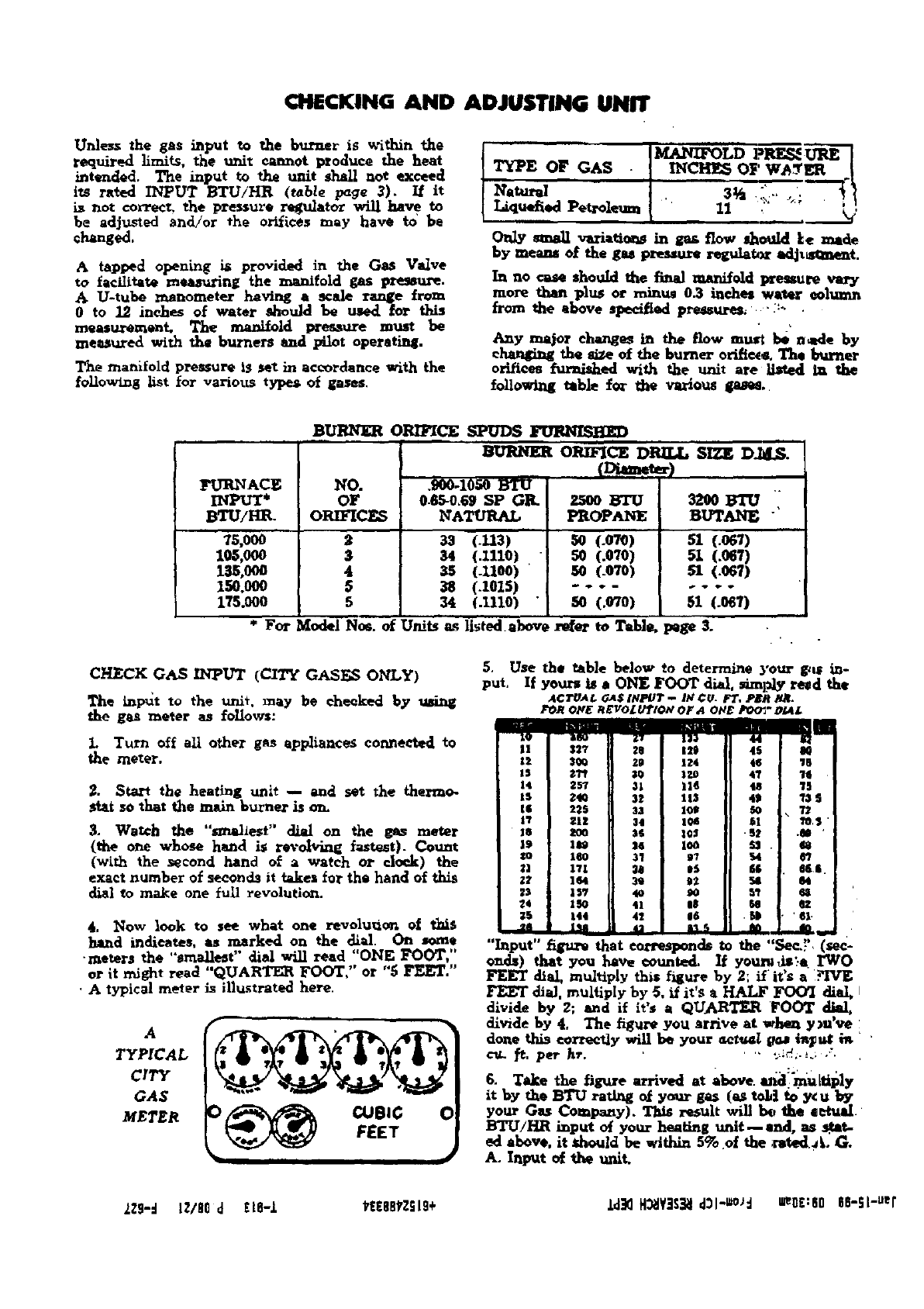
CHECKING AND ADJUSTING UNIT
Unless the gas input to the _rner is _dthin the
required limits, the unit cannot l_oduce 'he heat
intended. The input to the unit shall not exceed
izs rated INPUT BTU/HR (table page 3). If it
is not correct, _]le pressure r_ulator will have to
be adjusted and/or €he orifices may have to' be
changed,
A tapped opening is provided in the Gas Va]ve
to facilitate measuring the manifold gas pre_m-e.
AU-tube manometer having ascale range from
0to 12 inches of water should be _ _r this
measuron_ent. The mare/old pressure must be
measured with the burners and _lot operating.
The manifold pressure is set in accordance with the
following list for various typea of gases
LT_E OF GAS •M_tAq_3LD PRESSURE {
Imce OF J
small varia_ in g_ flow shmlld ke made
by means o_ the gas pressure regulatA_ i_tj_t.
In no cas* should the final manifold lzressure vary
more than plus or minuJ 03 inches water column
from the above specif_d pressures_' _:_
Any major changes in the flow must be n_le by
ehangi_ the _ of the burner orifice. T}_ b_mer
orifices _ed with the unit are listed In the
following table f_" t_ various gas_..
FURNACE
BTU/HI_
75,000
I_,000
_,000
150.000
175.000
BURNER ORIFICESPUDS FURNI_HI_ i
ORIFICE DRILL SIZE DJd.S.
NO.
OF
ORIFICES
3
4
5
5
0.65-0.69SP GR.
NATURAL
33 (.113)
34 (11110)
35 (.1100) '
38 (.1015)
34 (.1110)
zsoo BTU
PROPANE
so (.ow)
so (.o_o)
5O (.O7O)
so (.o_o)
32OO
BUTANE "
51 (.o6D
51 (.O67)
51 (.O67)
_1 (.061)
* For Model No_. of Units as listed.above re,or to Table. page 3.
CHECK GASINPUT (C_.JTYGASE._ONLY)
The inlet to the unit, may be checked by using
the gas meter as follows:
1. Turn off all other gas appliances cormeeted to
the meter.
2. Start the heating uni_ -- and set the thermo.
_tat so that the main burner is ,m.
3. Wazch the "smallest" _ on the &,as mater
(the one whose hand is r_'olving fastest). Count
(with the second land of a watch or clock) the
exact number of seconds it takes forthe hand of this
dial to make one _ul]revolution.
4. Now look to see what one revolu_on of this
band indicates, as marked on the dial. On some
•meters the "smartest" dial will read "ONE FOOT,"
or it m_ght reed "QUARTE_ FOOT," or "5 FEET."
•A typical meter is i|]ustrated here.
A
TYPICAL
CITY
GAS
METER EET
5. Use
put, If the _able below to determine your gin; in-
your_ is • ONE FOOT dial, _nFAy re_d the
AC_JA_ G_$ INPOT -- IW¢_, FT, PER H.q.
FOROFE REVOLU_IO,VOF,40H_ FO0_,-OLa£
I ]tl_ 1| IT | |11 I 4[4 , _1_
,, ..[I.1,. I,,,.
18 3_ 20 124 4S 'IB
IS _'rf [I 30 I IZO 4"/ 11_
14 287 IJ 31 i II_ 48 T5
IS 22S 33 10_ $0
|'/ _'|1 34 I0_ 61 " $ '
18 200 _$ |0:1 - 52 ._ '
19 11_ II Is I leO I £1 . $8
zo 160 I! 31 I87 , $4 65
zl lVl II 30 I 85 J $$ . 0&$.
:'2 164 )l 3S I$2 [_ _4
28 1BY II 4o ISO $'t a:l
24 15o II 41 | 18 SO ,oz
_5 144 II 41 Ig6 _ • ' 61.
"Input" _ that corresponds to the "See..'-'. (sec-
onds) that you l_ve counted. I| your_ls_-g I"WO
FEET dial, multiply this figure hy 2; if" it's a YlVE
FEET diM, multiply by 5, Lf it's a HALF FOO'I diaI,
divide by 2; and if it's aQUA_ FOOT dial,
dlvide by 4, The figure you arrive at when ym've
don_ this _rree_y will be your _ct_l ff_ i_u_
cu,.. fl:, per h_'. ";/._-_.; ,".
it by the BTU rating of your g_ (_ to_| to"y¢ U by
your Gas Company). This result will _the eeht_.
BTU!H_ input of your .h_, ring unit--end, as $_tat-
ed above, it zhould be within 5% of the :stedaL G.
As Input e_ *he unit.
zzg-d IZ/BOd ELS-Z _E88_Z_L9+ .b:i_ H_lYJS_ld31-u_d u_0£:80 SS-SL-.sr
_LU_ (_Z_.D,m) _ • _o
BLACK (K_ ...... "--'--'_i_,_" :
e__- •
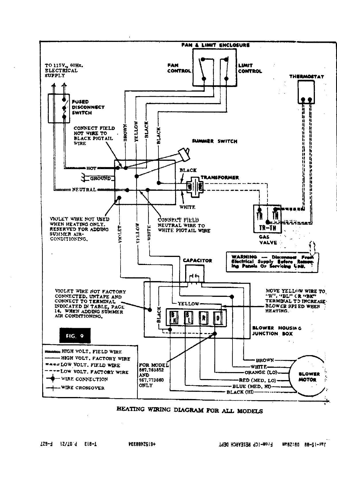
HEATING WIRING DIAGRAM FOR ALL MODELS
kZ9-d IZ/L6't [16-1 PEEOO_ZSL9+ J_ H_YISIEI d31-ui°ld mesz:80 86-Sl-_er
CONNECTING THE WIRING A) RECOMbLY.NDF2D GROUNDING _:OD
make all ne_e,umry electrical c_mections. Comple_ with the National Ek-ctrical Coda a_l
your e!eCt_ca_ woa'k ae¢_'_i]_. Remem'oe_r, how _ _x_ce_. Use a conductoa" o_ tJ_e apl_-.tate
ever, all e_ work must con/otto with the size (#14 AWG Copper) from the al_]i_m_e to ra_
require_lte_ts of your local _'dJnances s_] tl_ grounded connection in the ,,_-vlce panel or a _ •
Natioxm] Electrical Code. _you arc not [amlli_ erly driven and electrically grounded grov_[..rod.
with the proper _tring med_ods, we sug_t that
you purchase our ]x>oklet "Electrical Wiril_ for
Home and Farm". Form No. F5428, for sale at
nominal oost in Sears Retail and Catalog Order
Stores.
Note particularly that wiring for the heating unit
should orisinate st the Entrance Switch, and be a
separate (-used drcuLt out of this switch (rather
than be a branch line from some existing circuit).
In order to properly fuse this circuit and to Idm-
ultaneously provide a _ switch for the whole
heating system, we recommend that the hot (black)
wire pass through a Fused Discoane_t Switck
Use No. 14 or larger size wire throughout, except
where tlm illustrationindicatesthat bell wire (low
vo|tege Iin_) is s_Eficieot, Fuse the circuitat the
(fused di_orm_ct switch) _ a TLmed-Lag _
not over 15 amid. sbze.
ELECTRIC GROUNDING
Electric ground is requiredon thisappliance.
=
B) ALTER_ATE GROUNDED METHOD ....
If tim z_,ommended grounding method is
•ible, permanently ground the app]iam_ flora the
gromut €_mector to a zround_d €old water l_Te"
using a separate, green colore_ ia_ml_tod eoadt_:tor
_E_m_e. THIS HOWEVE_ l_ NOT.
*Cold water pipe must ha_ met_ ¢o_tlz.nity:to
_ort_ical ground a.d no_ be interrupts by
rubbe_ or other electrically ir,b_ati._g oog_ect0cs
(tne!uding water meter or pump) without adding a
Jmr,l_r wh'e at theft eonnecfioi_. - ..-
NOTE: Do not 8round to a gas supply ptpe. Do not
connect to electric power supply untid a_dm_ee .i_
pe_r_ently _rounde<L
iIf you have done the Jastella_ion )_se.]_ we
_ecom_end that you now _II upon the sm=-
est Sear_ Serviee_T_bnicinn_or the Ga_
Company--to make the fotlowing e.heek_ a.d
adjusun_s. He will have the _ i_¢ru_
ment_
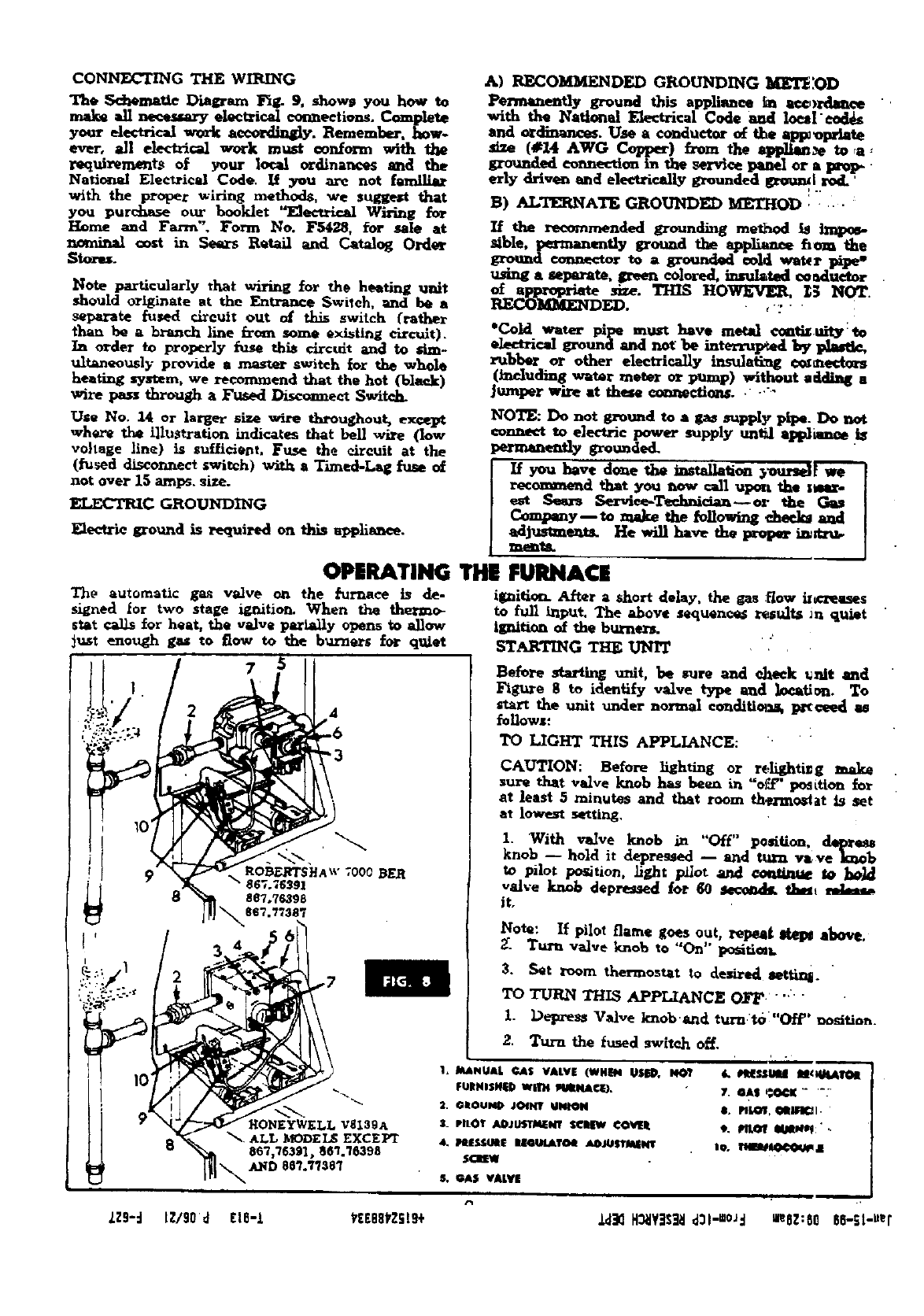
OPERATING THE FURNACE
The automatic gas va2ve on the _'urnace is de- ignition. After ashort delay, the gas :_ow il_:z_L-es
signed tor two stage ignition. When the the_-mo- to full input. The above sequences ves-lt_ Jn quiet
st_t calls for heat, the veJve par_ally opens to allow Ignition of the burner_.
_n._t enough gas tO ROW to the bunlers for quiet ST_TII_G THE UNIT
8
Before starting unit, be sure and eheck _nis and
_g_e 8 to identify valve type and k_ation. To
start the unit under normal co_tditiol_& p_rt_ a_
follows:
TO LIGHT THIS APPLIANCE:
CAUTION: Before lighting or re4ightisg make
sur_ that valve knob has been in "of'£" po_ttton for
at least 5minutes and that room th_rmos4at is set
at lowest retting,
1. With v_ve knob in "O£f" position, d4q_
knob -- hold it depres_,d -- and ttwa vl_ve knob
tO pilot portion. ]if,ht p_ot and €o_iRt_ to boL_
valve knob depreumd for 60 _tlbm_
it,
Note: If pilot flame goes out, repeat _ above.
_. Turn vffilve knob to "On" portion.
3. S*t room thermostatto desire_ s_t_.
TO TURN THIS APPL/_NCE OFF .....
I. Depre&s Valve knob'and turn t6"Off" _ositio..
2. Turn the _used _r_lt_ o_.
1, MANUAL @AS VALVE (WHir40SED, 140?
FURNISH|D WllrH Iq_mNA¢_},
S_ pilOT AOJUST_k'T seldw ¢ovEIt
&PllESSl_tl_ eS@UtATO_ ADJUSTMENt
$€I_EW
m
7. @AS P.@¢K.... :
t, _lr I/mmw; ..
S. GAS VALVE
LZ9"d tZ/90d EIB-L YEE68VZSI9+ .Ld_2H_Y_S_ d31"=°_d =eGZ:80 SS-St-.er
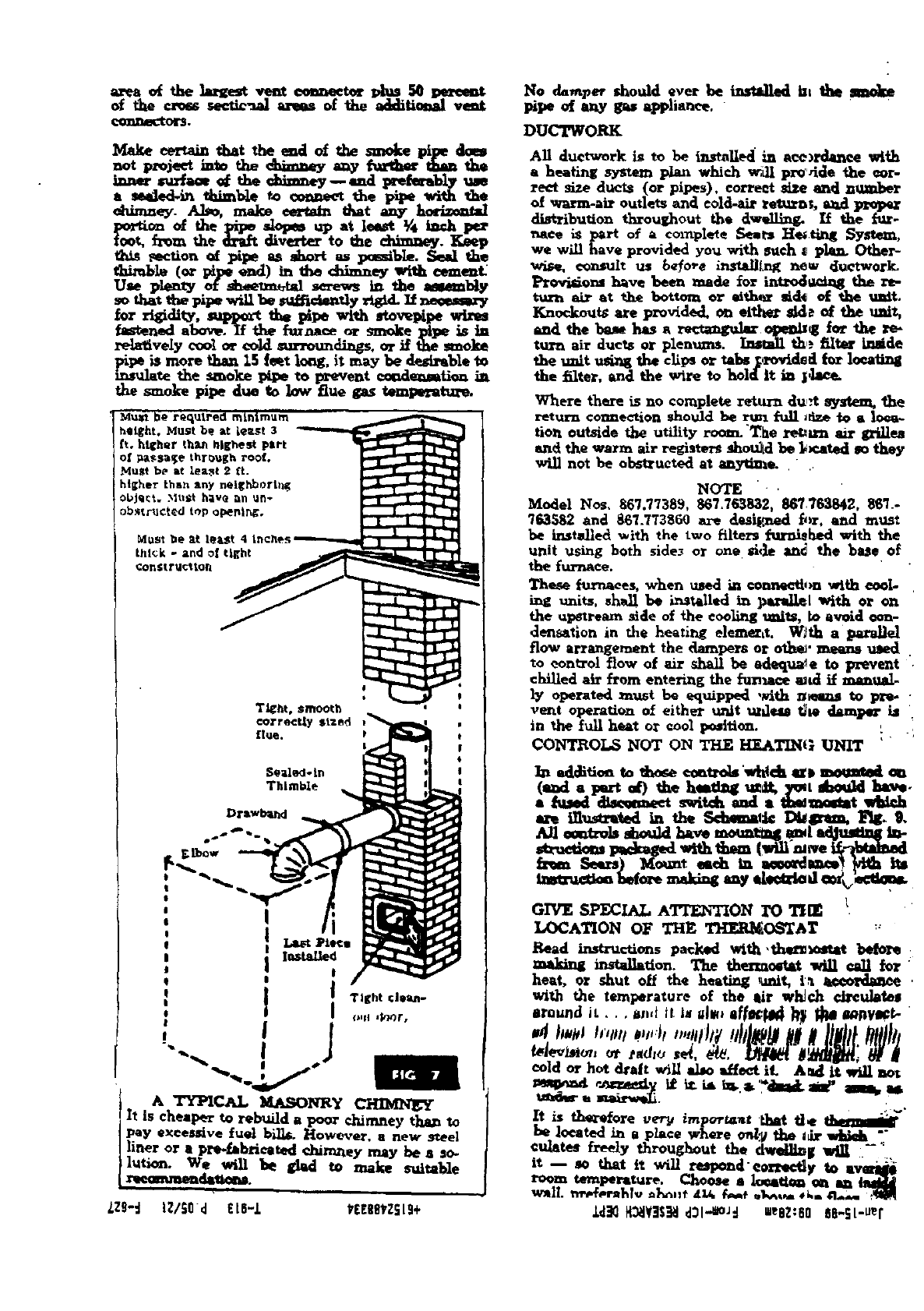
area of the lareS, vent eem_eetef plan se _,_at
of the _secuc'aal areas of the additi_al vmt
gonl_eCto_.
Make _ that the eul of l_e smoke pipe dam
not pz_jeet into the <_tney _ _ _ the
_r/aa* _ the _-y--and pre_bly _e
a reek.d-in thimble to eoaneet d_e pule with the
_dnmey. Alto, make eerts/n dmt any hm-tzont=l
_¢ti_ of the pipe slopes up at leeutt _'4 inch pex"
toot, _m the drift diverter to the chimney. Keep
t_ _ctXon _ pipe as short as p_mible. Seal the
thimble (or p_pt _) in the _ey with cemant_
Use plenty of sh_._n_tal screws in the amembty
so tha_ the pipe will be mdfictemly _d. It neeum,W
for rigidity, rapport the pipe with stovepipe wires
fan.ned ahoy. If the _maaee or smoke pipe is ta
rela_ively c_ol or co_d _rrotm_ags. or J_the smoke
_te the smolce pipe to prevent _e_mtion in
the s_oke pipe due to low flue gas temperatur_
Drawbargl
No damper should ever be insttlled bt the Jmoke
pipe of any gas appliance. "
DUCTWORK
All duetw_rk is to be i_alled in ace)rda_ee with
aheating system plan which _,dl pro dde the cor-
rect size ducts (or pipes), correct _ and n_
of warm-air outlets and cold-air retrains, mad
distribuUon throughout the dw_ing. If the i'_r-
_ace is part o_ acomplete Seats He_ting System,
we will have provided you with such _ p]a_ Other-
wire, _It us _e_o_e inste.Ul_ new duetwork_
Provi_ens have beea made for iatr_ the re-
turn air at the bottom or *lth,_ _d_ of the unit.
Knockouts are provided, on eithe_r sk]_ of the uni_,
aud the ba_ has a r._angular opeu_ for the re-
ttn_ air due_ or plenums, Lemladlthe filte¢ Imide
the unit u_W the clips or _abe S_ied/_r loeati_
the filter, and the wire to holdit in ]_tee.
Where there is no complete return du,.t system, "the
return connection should be rm_ x%dl_fize to a Ioea-
tio_ outside the utility room. "The re_ma air gz_lea
and the warm air registers should be l_.ated so they
w_ not be obsUructed at any_]_.. " ..
N_I'E • .
Model Nos, 867.77389, 867,763832, 86T763842, $6_.-
"/63582 and 867.773860 are &_signed _,_, and must
be instadled with the two filtez_ furnished with the
unit using both sidesor one _i&e and the base of
the furnace.
These furnaces, when used in €ommeti,n with cool-
Lug units, shall be L,_talled in parallel with or on
the upstream side of the eoolb_gtraitS, to avoid eon-
densation in the heating eleme_tt. W_th a parallel
flow arrangement the dampers or oth_" means used
to control flow of air shall be adequate to prevent '.
chilied air from entering the fun_ _d if manual
ly operated must be equipped ,_th n_z_ to _ •
vent operation of either unit uldeas the dami_- i_
in the full h,_t or €ool position. : -i
CONT_OL_ _IOT ON THE H_ATINi; UNIT ''
]_a _ldRio_ to those _tzok'_'_ch _ momm_l
(ead apart of) the h.atlag ue_ ]m,t abe.k1 hay..
nbused dlsemaeet switch imd a _moutat w_--eh
GIVE SPECIAL ATTENTION I"0THE
LOCATION OF THE THERMOSTAT
Read instructionspacked with ,thet_ beb_
making installatlon. The thenamtat will _II for"
heat, or shut oH the heating unit, i._ tweordaaee .
with the temperature of the sir wl_ch cireu]ateg
around it, , , and iI is alt_ II_ll_41d _ _1 d_Vll¢_" "
t_Jev_o_,oi"radio
cold or hot dralt will _ IHeet it A_d it _I not
£ •
It is th_¢_ore ve_ important Lhat tie tla_.mig _
be |oeated in a place where on_/the I_t"wttieit ""
©mates freely throughout the dwei_lg win -';
it -- _o that it will respend'eorte_y to ever_
room temperature. Choose a Ioeat/_ _ma lalt11_
wall n_T_.rahlv _,t _iA €_,,_ o_. ,t., n.J. ,'_q
_2 H_i¥_l d3l-.eo.Jd "eOZ:80 86-SL-Uef
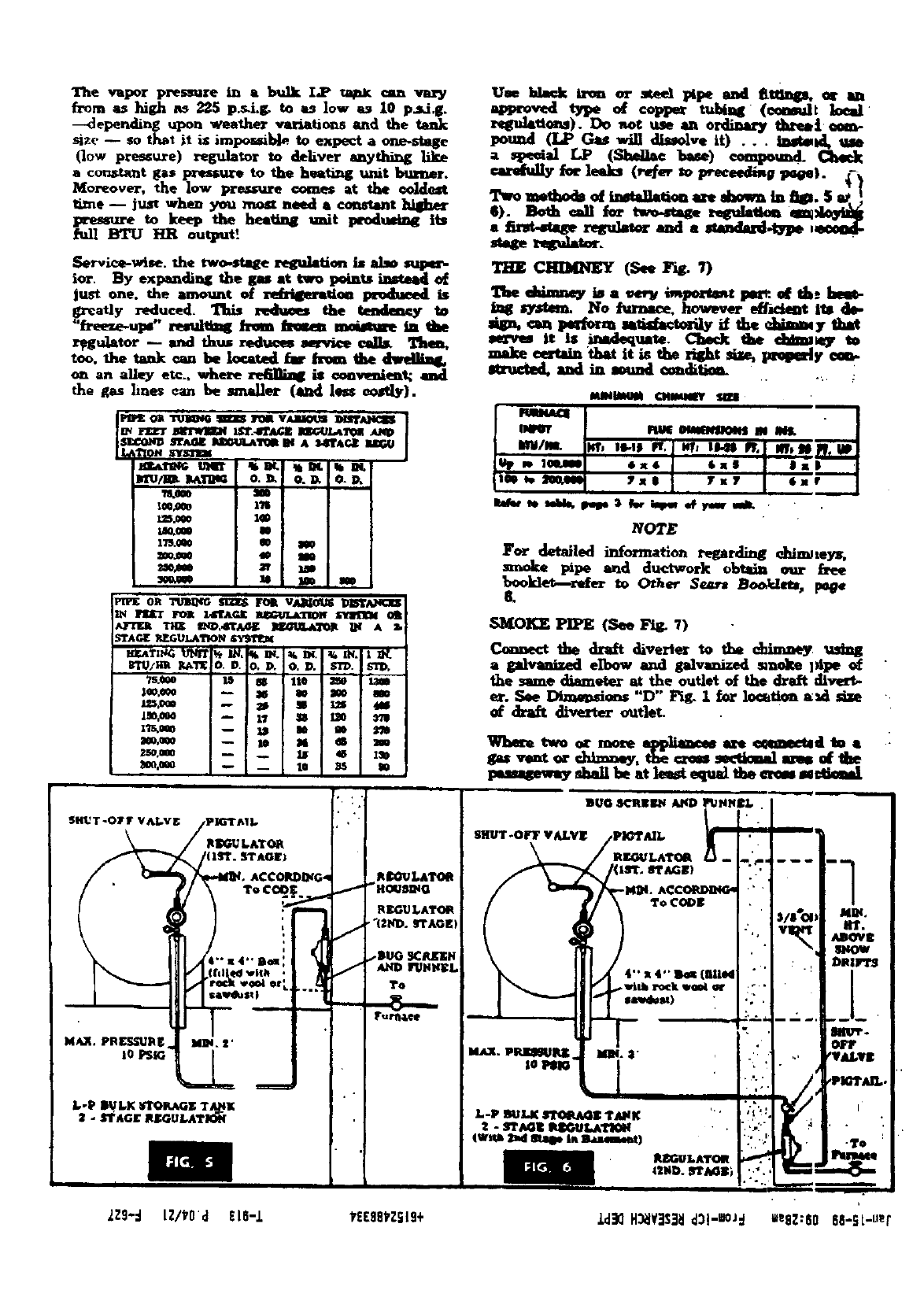
The vlpor p_esmJre in abulk I.P ta_x am _try
from as high ns 225 p._i.r_ to as low as l0 p.sd_.
--<]epending upon weather v_tio;-.s and the
-_ze -- so t_t it is impor,_b]e to expect a o¢le-stage
(low pressure) reg,,l_r to _Lv_ anything
a cons_t gas _to the he_ _t _r.
bior_over, the low pressure comes at the ooL:tost
time -- just when you most need a _nstant hiSher
pressure to keep the heetin8 imit l_'odu_m4_ its
full BTU _output'
U_ _iron or _lzl_ and fttm_, _am
_o_stppe o_ coppe_ ruble (emmdt looml
). Do _,oc use an ordim_ th:e_t _m-
pound (LP G_ will dl_ve it) .. , l_to_ u_
l'wo mechocko_t.n_U_tio_ _d_va In _. $_.
_). Both all for two..zU_ z,_da_lon eldoWl_
mmse t_S_.tor.
AC¢ORDm_
To CODI
I
LZ9-:J LZIPO',:I ;'16-i YEE88PZSI9+ _d_ H_VBS_I _I -IOj'l ileAZ:80 88-St-uep
It isve_ important, too that you son, hue to main-
tain your heatingplant--after It is In operatiem
--by xegxdarly pe_ the minimum mainte-
nemce (peges 14 e-d 17) which we have li_.d.
OTHER SEARS BOOKLETS TO HELP YOU
*FormNo.Fl17_--HowtoInstal]Phunbing.
*FormNo.F12967--How _o InstallForcedAir
HeatingandCoolingSystems.
tForm No.F'c4_S--_ectrkad_ _.. _ ,,,..A
Farm. "" ""
*Free Obtain _om _umbing D_'t. i. Retail Stow
or write to Dep t. 243 at Catalog erder St0_.
SNormnl tort: Obtain h_m El*six-levi Dep't in
I_tail Storeor write to Dep't.Z4S at Catalog
Order Store.
INSTALUN8 UNIT
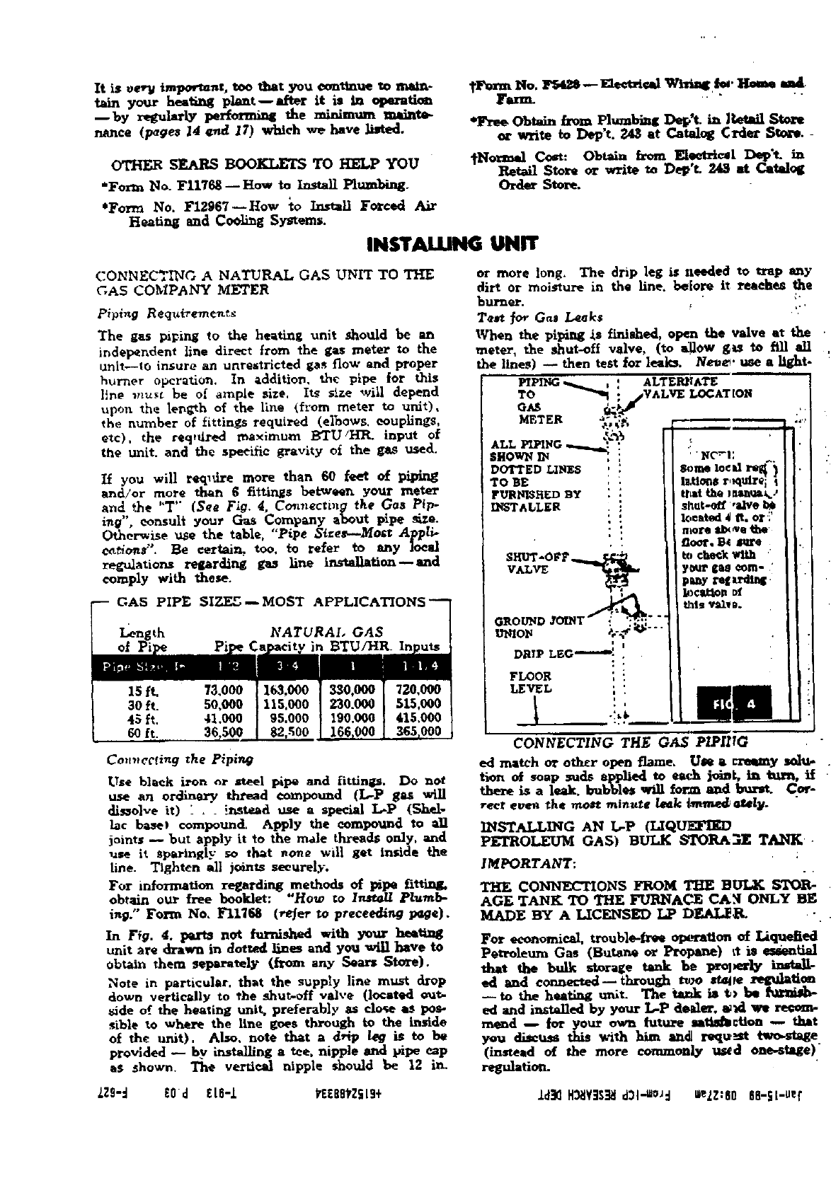
CONNECTIIxCG A NATURAL GAS UNIT TO THE
C,AS COMPANY METER
Piping Reqtti_'ements
The gas piping to the heating unit Should be an
independent line direct from the gas meter to the
unit--Is insure an unrestricted gas flow and proper
burner operation. In addition, the pipe for this
li_e _nust be of ample size. Its size will depend
upon the length of the line (from meter to unit),
the number of fittings required (elbows. couplings,
etc), the req,dred maximum BTU/IffR. input of
the unit• and the specific gravity of the gas used.
H you will req_dre more than 60 feet of piping
and/or more than 6fittir_s between your meter
and the "T'" (See Fig. 4, Co,meeting the Gas Pip-
i_g", consult your Gas Company about pipe _ze.
Otherwise use the table, "Pipe S_ze_--Most gppli-
set,ions". Be certain, too, _refer to any ]oe_
reg,_lations regarding gas line installation--and
comply with these.
GAS PIPE SIZEE -- MOST APPLICATIONS--
Length NATURAL GAS
of Pi in BTU/HR.
left.
30 ft.
45 ft,
60 ft.
Co.,_ccfing the Piping
Use black iron or Jtteel pipe and fitting1_. Do not
use an ordinary thread compound (I,,-P gas will
dissolve it) _,. instead use a special L-P (ghel.
Iac base_ compound, Apply the oomlmxlnd to an
joints _but apply it to the male threads only. and
use it sparingly so that _one will get inside the
line. Tighten all joints securely.
For information regarding methods of l_pe fittinll.
obtain our free booklet: "How to last_R Plumb-
ing." Form No, Fl1"/68 (_er to preceedim3 p_e).
In Ffg. 4. parts not fur_shed with yo_r heaemg
unit are drawn in dotted lines and you win have tO
obtain them _plmate]y (from any Sears Store).
Note in particular, that the supply line must drop
down vertically to the shut-off valve (located out.
side of the heating unit, preferably as close as pos-
sible to wh_re the line goes through to the inside
of the unit). Also. note that ad_ip k_ is to be
provided _by instsdling a tee, nipple and pipe cap
aS shown. The vertieal nipple should be 12 in.
CONNECTING THE GAS PIPIITG
ed matchor otheropenflame.Ule acl-e_yIa_I,,I-.
tiono_soapsudsappliedto eachjoint,in time,if
the_ isa leak.bubbles_formaud bur_ Co_-
rect even the _minute leak |_nm.e_agel¥.
INSTALLING AN L-P (LIQUEFIED
PETROLEUM GAS) BULK b_ro_3 _- TANK l-
IMPORTANT;
CO _ ON S FROM _ B_ _ 1
AGE TANK TO THE FURIqAC_ CAN ONLY BE
MADE BY A LICENSED LP DEAI_g. -.
For economical, trouble-free op_Tatlon of I.iquetied
Petroleum Gas (Butar_ or Propane) _t is _eaat_l
that the bulk storage tank he proporh, imgalb
ed a,d e_--throu_, t,.o,t_e remda.ti._
-- to the heating unlt. The ia_k m t> _ _u_anm-
ed and installed by year L-P de_der, _d we
me_d -- for your ow_ future lat_l_¢_n --, that
you di._11._ thiswith hi1_ a_._ I'equ'_tlwo.-stege
(insteadof the more cornmo.ly u_d one_t_ge)
regulation.
LZ9-_ EOld £L811 _E£BEYZ_Ig+ .Ld_ H_Y]$_I d31"_s_d _eLZ:80 68-SLluer
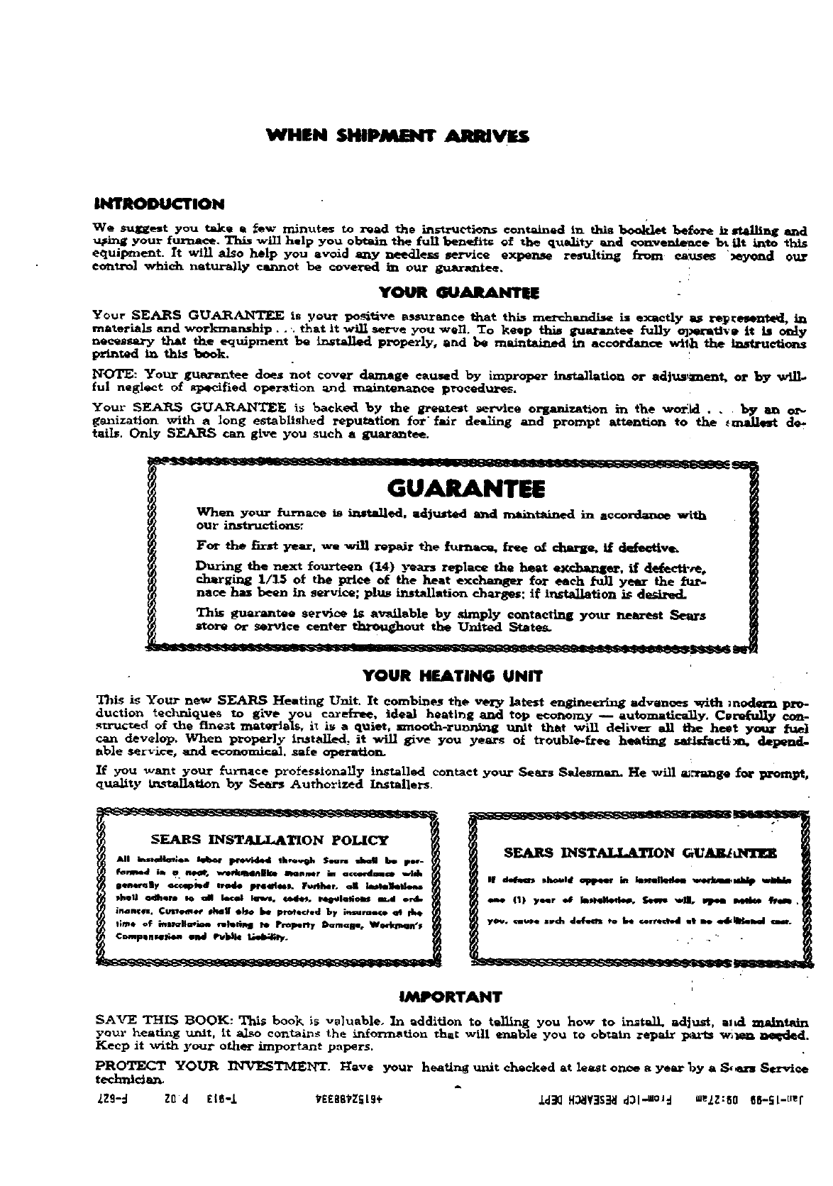
WHEN SHIPMENT ARRIVES
INTRODUCTION
We surest you take a fQw minutes to read the instrurtion_ contained in thta _before h _lliag and
upin_ your furnace. Th_ will help you obtain the full ben_di_ of the qu_dity and convenience bt Ht into thls
equipment. It will also help you avoid any needless service expense resulting from e_uses )eyond our
control which naturally cannot be covered i_n our guarantee,
YOUR
Your SE._RS GUARA.NTF_.E Is your positive assurance tiler this mere.handi_ i= exactly lu_ rel_re_nted, ill
materials and workmar_hlp.. -. that It will serve you wen. To keep th_ guarantee fully o]_tive it is only
necessary that the equipment be instaJ!e_ properly, and be maintained in accordance wtt_ the Ia_ruetl_
p_ted in thts book.
NOTE: Your guarantee does not cover damage caused by improper installation or adjt_ent, or by
ful neglect of Sl_cified operation _d maintenance pr_)ced_.tre_.
Your S EAI_. GUARA_I_E is _acked by the _e_test service organization in the wor.Ld. .by an or-
_Izatlon wlt_ mlong estahllghed reputatlon for fa6r dealing and prompt attention to the ,,_ de*
tails. Ordy SEARS can give you such a guarantee.
GUARANTEE
When your furnace ls installed, adiusted row1 maintained in aecordanoe with
our ir_tructioats:
For the firstyear, we will repair the _rna_, h'ee o_ charge, if de_etlv_
During the next fourteen (14) years replace the heat excJ_l_gar, if defecti'_e,
charging I/L_ of the price of the heat exchanger for each full year the fur-
nace ha= been in service; plus installation charges: if lnsta]_tion _ desired.
Tht_ guax'a_me service Is available by simply €or_tectll_ yottr nearest Sears
store Or _er_lce center t_mu_out the United States.
YOUR HEATING UNIT
This is Your new SEARS Heating Unit It combi._es the very latest engineering a_vanees with :nodenl InV-
duction tec]_nlques to give you caxe_'ee, ideal heat|r_g _ top economy -- automatically. C_refl_ con-
structed of the finezt materials, i_ is a quiet, srnooth-runn_g unit that will deliver all t3"ae heat ymar fuel
can develop. When properly installed, it will Eive you years ot trouble-f_ee h_t_tinE satan-acrid, depen_
able Service, and economical, safe operat_ol_
If you want your £urnace profes$1onal]y in_tall_ contact your Sears Sldesrnml. He will a_-ange _r In'mnp_
quarry tr_tanaflon hy Sear_ Authorized Installers.
SEARS INSTALI_kTION POLICY SEARS IMSTAJ.L&TION GU&IM_brTI_
_f _ _lw_ad _ ie k_m_km _mb¥
IMPORTANT
SAVE THIS BOOK: Thi_ book is v_]ueble. In addition to telling you how to in=ta_, adjust, arid. ma/mtl_x
your _.earing uzatt, It a1_o eantains the information that will enable you tO obtain _epair l_rt:s w_le_ IM_ded.
Keep it with your other important pnp_r$.
PROTECT YOUR ISIVESTivIEI_'T. Have your heating unit checked at least once e year 1>3,a S,_."s Service
teclmtcia_
Lzg-:l ZOd r|E-I YEESB'kZ_L9+ l_ H_¥:IS_I ,:131.-,=oJd =e2Z:80 8_-St-tmr
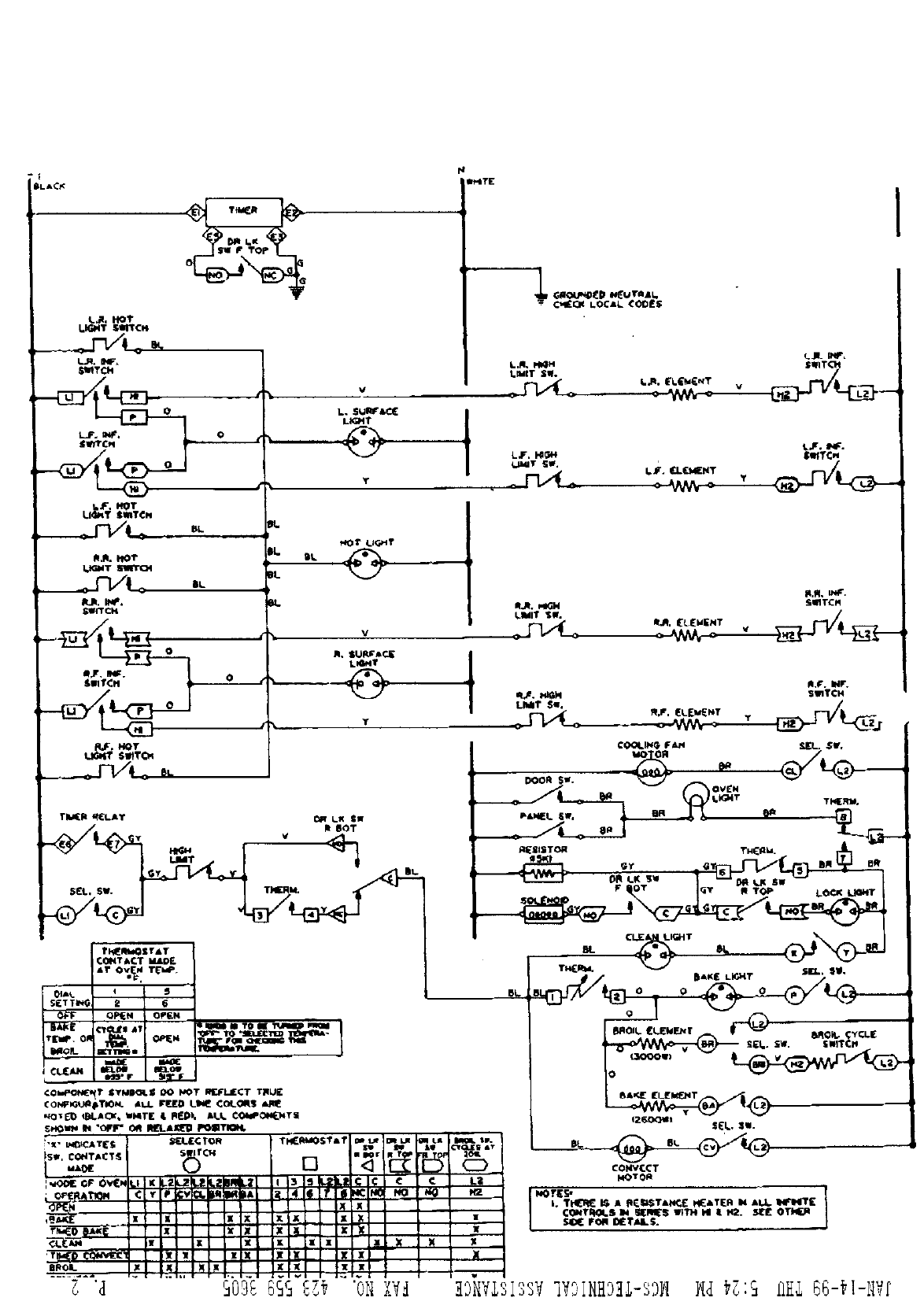
gLAC_
k_. h_T
U_IT SmTCH
_TCk
¢
LiGI_T $mTCH
R,R. hO_"
L_T
RJk, INf,
SWITCH
0
V
T
_Ot Ll_t
iv
d_Y
TiM(R q_LAY I_t LK SW
__ R 60T
GY Ill.
_ $W.__SLL'i.,SW. TNERU.
TE'UPfl 0
I CU[_
L
Th_RWOS raT
COHTACT M&IDI_
AT OvEN T_,
QPI[N OP£N
I_1_1 r I _S*lr
¢ONP_T STMIC_._ OO NOT mEfLIECT T_U[
¢ONF_i_TIO_. aUL FFJED LI_ ¢OL_$ _1_
s_O_ I_ "oitlr" OR l_aJ_ I_TKN_
ItROL
_ 'd
TI(RMOS_" a1'
O []
€l • I i' ICv_l,,li_ #I_WA I4!l!t!
111_I tl ::
••X X -=.._
xXIKI _: i
i !*!'!! !TI
xXX P_ 7: :
1
_JJ_ G_OU_DI[D *_uTaa_,
L,N, _,l_M SWITC_I
LJr. I_¢-_1
_IMJT 5W, mTC_
R_R. *'IGH SmTCM
R,l_, iNF.
1[
x
X
mw
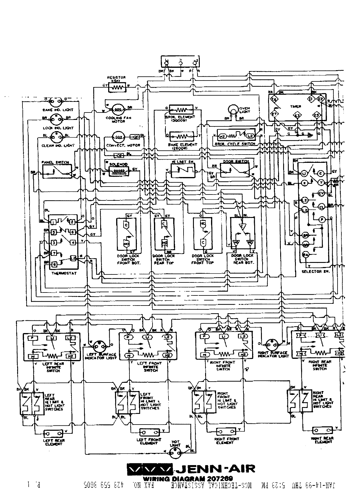
WININQDIAMAM207269
_3
G.
0_
D_
b_
_D
r,-
cr_
,--4
_:r
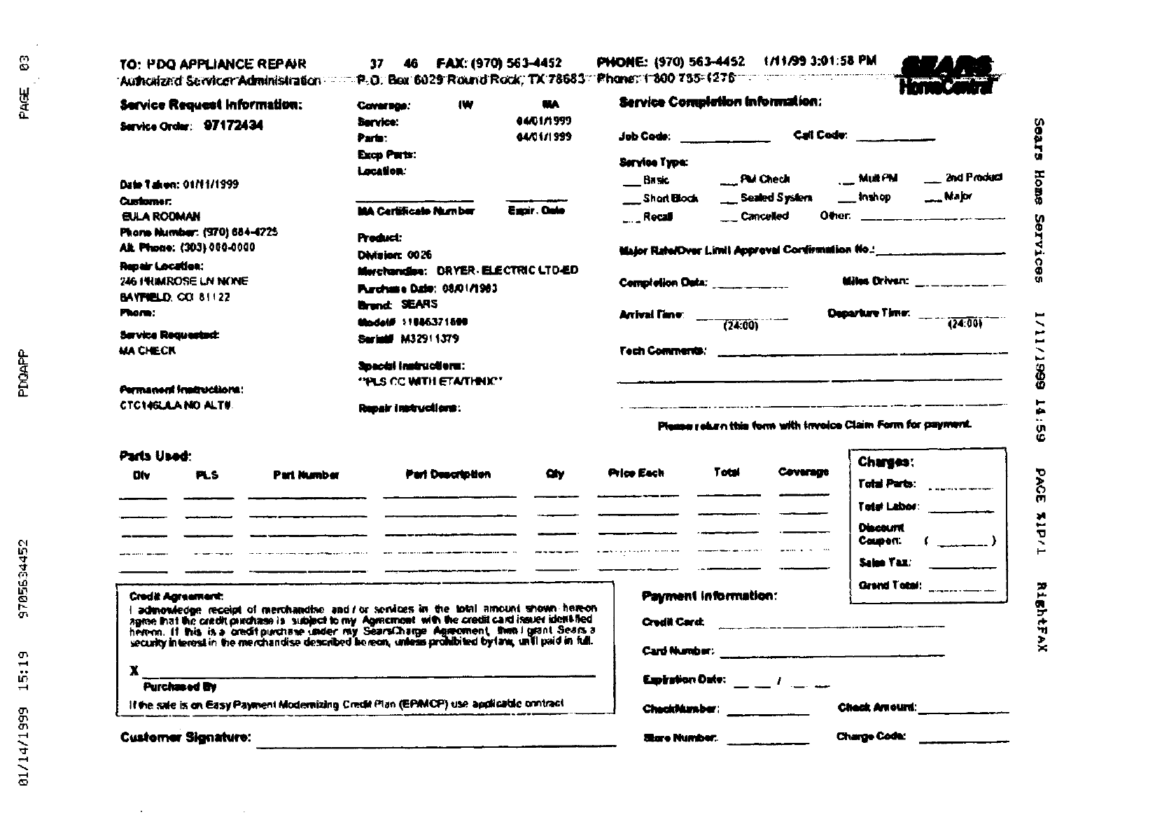
TO: IJDQ APPLIANCE REPNR 37 46 FAX: (970) 5_3-4452 PHONE: (970) 563-44S2 _/t tfJ_J 3.0! :58 PM
Service Requgmi Infm'meffau: r,m_qi*: aw m lklrvl_e _Infonnailoa:
S*n_,o Ordw; 97172434 Serd_: 044;Into
Padll: 64/0ill S439 Job Code,: €.ll4 Cml_
•lb Takg*l:OlM|llg<_
Cusiomer.
EULAROOMNN
Pkoru_Number:.(5'70)1S84472S
AlLiJtv_,: (303)000.0000
IteFW t.dsr._ee:
6AYI_, 0(3 81122
FItonle:
JMCHECK
Purmamml_nu:
CTC_46LA.ANO _LT#
E:scpPsns: 8_lee IrI_:
I.a,callo_
MAC4dillr.ak N_n b_ Emur _ .... ger.d __ Ca_eliled Offer:
FII31dMI_:
mv_le_ oo_
Mw¢handlm: ORYER•ELECTRICI.TO,ED
IqmSme Dad,: _0_/1N3
SEARS
_l_l M329__3/9
II_dll Imtg_llonl:
"'1_I.S _C IMTII ETkTHII_"
Imma_lem:
Flate_OwrLimll/_lw_vul C4u-,_muli_nNo.:'
¢._nlMdl_ O_b_: I_k_ Or_:
rein _:
_r ek_n ttli_ from with tm Clam irwin f_ paqmm_t.
Used:
Oiv PLS Pm Number PerlDes4_ntl_ Qly I_l_ Etch Yotel ¢.4vemip
.............. _ .................... _..... ,.......................................... ..............................
n-- --m
Credit_4r_emw_.
_cu_ k_m_l_n _me_l_an_ d_sc_il_d k _urdem praNbltKI t_tam; ,,roll _d bl ful.
x
Pur_.J_41 Dy
If _ _ is m_$yP_yme_l Mod_mlzl.g Cmd_ man(Ei=_dCP)us_ a_d_r..ebl©o_ntr4c_
Customw Sig_atm_:
ISaymemiInformation:
Numbur;
ch,d_und_:
ChmleS:
told Pwls:
Totl_Lab_:
Dt_x_
C_upoa: ()
SataeTu:
_eunt:
(_alp Ca_
[,I
_q
_q
o
U)
(D
<
k.d
_D
)..
'o
(11
a*
q..
'o
gq
<I
0_
{_I
LD
r_-
o_
T-4
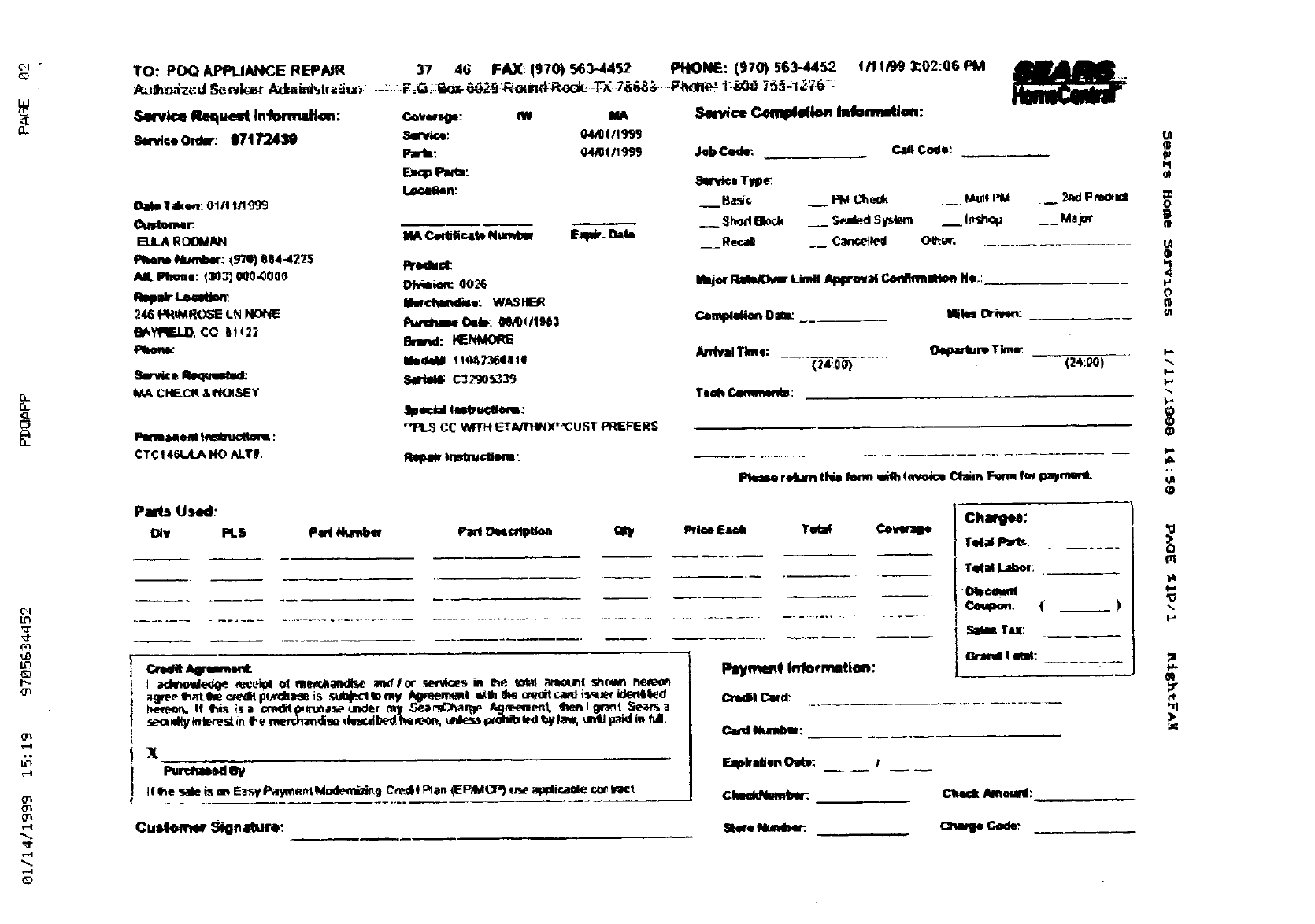
TO: POQ APPLIANCE REPNR 37 46 FAX_ (970) 563-4452 PIIIONF-: (970) 563.4452 _/'I 1/99 _02:06 PM _r_ _
AvJ'_Z._d S-_fi'l'.;e,_ .Z_r,.ni_,_-,d,v._v.: --:-.: P_G;:G_,-_;_.ER_,Jnd-R_o_v,._:'T'_ 7&6,,_ -F_:lle.'- "I:,I_0 _6_;12'._G :IGGiZSZa"
Service gequat la'l_l'_: c_v_o_: m IA _C_mpl_l_ IMIoemMIN:
semce Ormr: i17t 7"243_ Swv,kw. 04/0q_I_S
Paris: 04_!/1999 Job_.,4_le: Ca4 Code',
Oa_ I ak_,,z:Gift t,_999
ELLARO{_*I
Phone: t3e_ 0Q0.0000
l_lmllr (.._,l_oec.
246 _tMR(_-'ELN
6_Y_'IAELO,CO B!(2_
_rfvke Requwf_d:
t/A CI4F-C_&t_IU4SEY
Immaaee_l tf_ct_m
CTC !4G_LA NO N.T#.
_ow.
_Sl._rlelo_k Sealed S _er. I_h_ __ kt_p_
MA Ced_cste Numbw _. _14, __ R_.dl __ ¢_n_e d Oe'_er. ..........
Predud: _
D_k_c ,00_ Maj_r I_ _ _plpr_a] C,_lblm_ Ne.: z..,.
Pw_Ya_ _. 08/0_/_9_3 C_mp4Mion Oa_ Miles _,.n
8,1nd: HF._
MedeUII t lq:__llil IU
SpecialImP:
-PL_ CC 'MTH _T_X'_URT PRIEFERS
Anlvai Tim e: (_N_um Time:
-- - (24--:.O-G_-...... (24:00)
Pa_._ Used:
Oiv PLS par(N_b4_ ParlD4m_ptkm
X
pur_l_ld _y
II I_e _zdei_ _EasyPalRne_tM_m_g Credit_an _EP4vqt_)(J_ _l_ic_lIMe_ _:1_t
Cus4_r_ S6gnature:
PaymeM infocmatlon:
Ci_dll C._d:
r._arlleS:
T(dM Labor;
€_l_©oum
i,._ TPJ:
¢,i,d Numi_:
¢_ _m_:
k-,
®
t-,
,,Q
rq
14
t-,
,Q
%
,11
).
<T
mBImXgWAqk_l
o_
_t
L_
_0
O_
0_
,:r
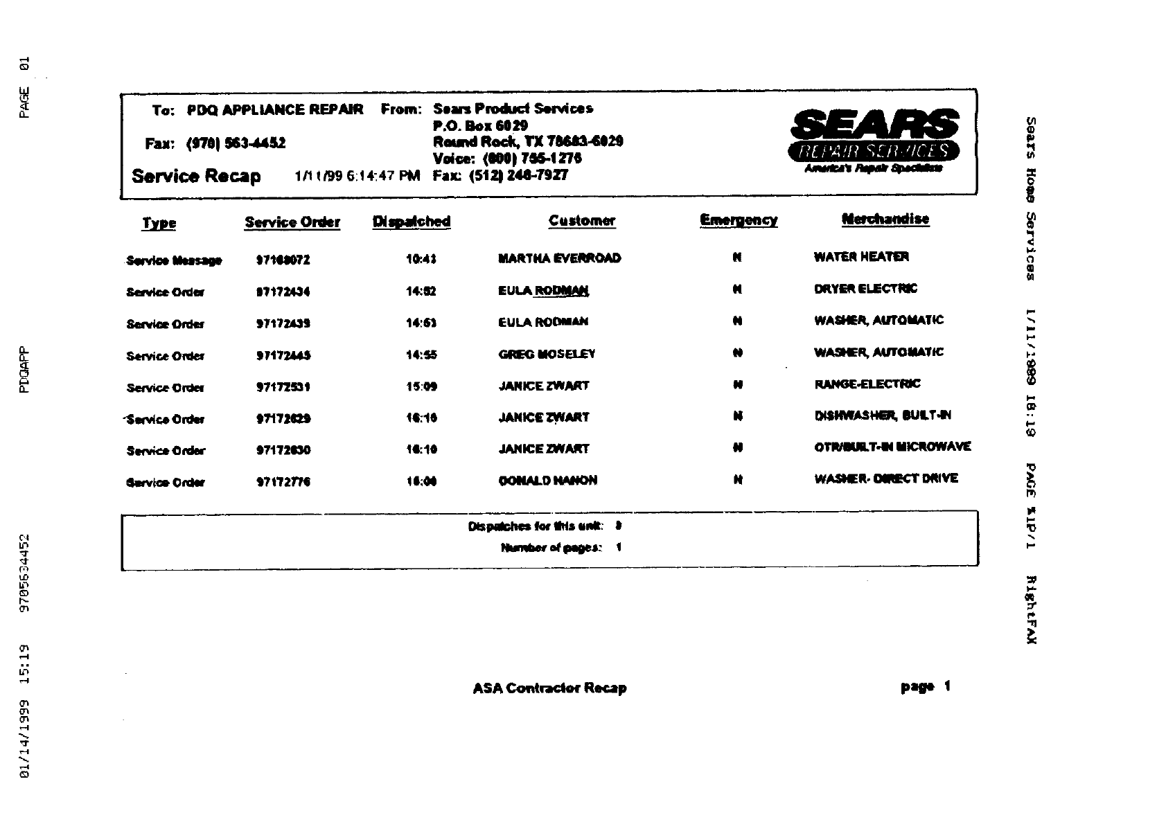
To: PDQ APPLIANCE REPAIR
Fax: (fTel ss3.a_4s2
Service Recap
From: Sears Produd Services
P.O. Box 6029
RoundRock,yx TMa3..U29
Volf, e: (NO 1 7M-1276
1/11/99 G:_4"47 PM Fax: (512_ Z44-79Z7
Type Smk;e Onler
Serd_ ttwsage t714N?2
&e_k_ O_der |T17:_34
84urvlceOrder 97172439
ServiceO_4_r 9717244S
._,en_.e€lrdew 971775_1
_ServlcoOrdw t?17H_9
Serv_e O_ler 97172030
_kwv_mOrdl_ tTtT2T/G
Diqpa_hed Custonwr
10:45 MAATHAEVERROAD
14_m EUt.A_
t4:M. EULA RODM_I4
t4:55 _MOSELEY
15:09 JANK:EZWART
t6:10 JANICEZW_RT
14:10 JANICEZWART
! I:M OONNLOHM!ON
Dispair,hes kNrIbis unit: I
HunVa_ ef I_leJ: I
14
N
N
N
N
N
N
H
w _v_ur _,_ceab_
_ise
WATERHEAlrl0q
OltYl_ ELECTRIC
WASHER,AUTOMAI_
WASHER,AUTOMATIC
RANGE-ELECTRK:
OI_HIWASHER,OULT.t_I
OTR_IUILT-INIMICROWAV[
W_SNER. OiRECT0_VE )
ASA ¢.oNraclof Recap page 1
<
¢1
®
im
F-"
k*
0:
t-
r_
im
'0
p.,
W*
4_
-q
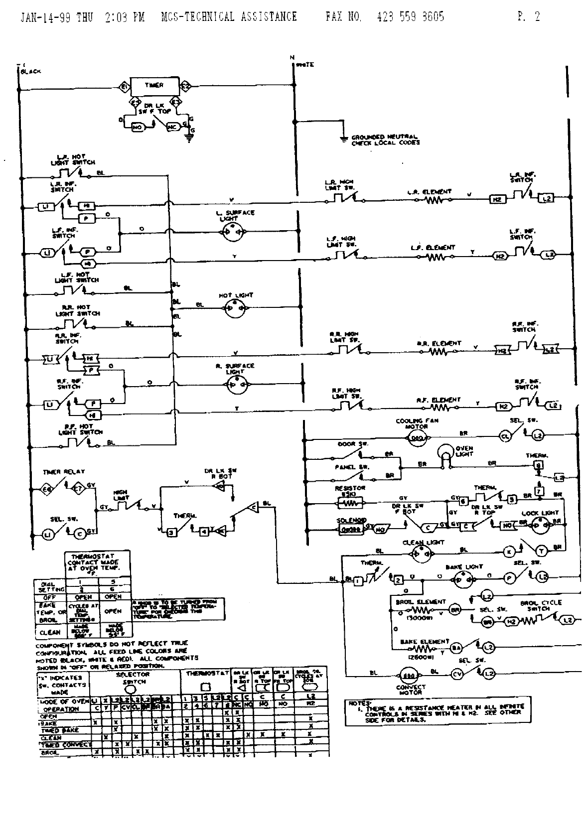
JA11-14-99THU 2:03 P_ _Cg-TECNNICALASgl,gTANCE FAi NO, 429 559 3805 P. 2
[
61.JCK
14.
msT[ I
"o,trcx L_AL CQ_E5

¢
IENN "AIR
WIRING OIAGRAM 207_
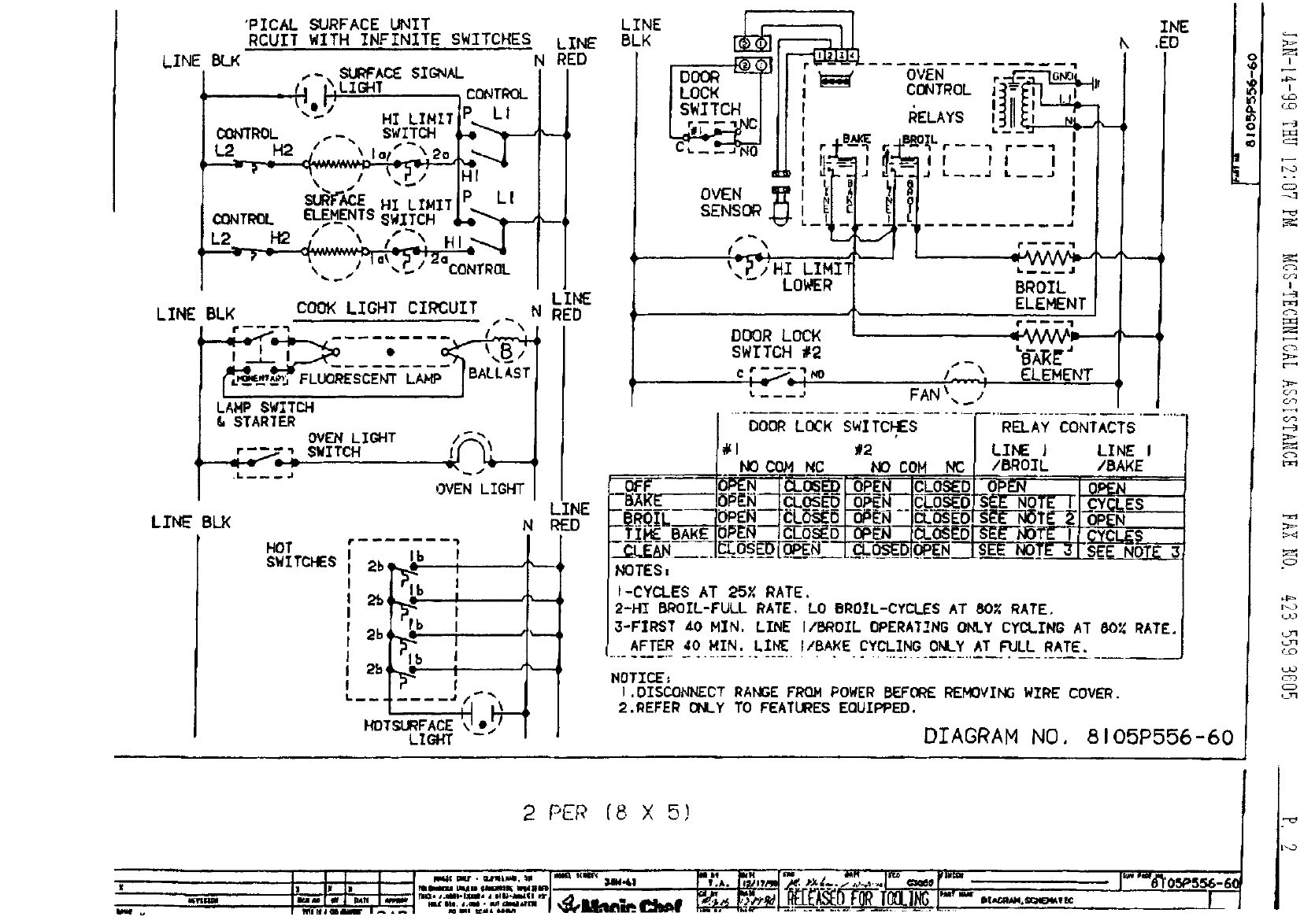
LINE BLK
"PICAL SURFACE UNIT
RCUIT WITH INFINITE SWITCHES LINE
N RED
,,.- SURFACE $IONAL
_Ii I\ILIGNT CONTROL
_LtVHI LIMIT PEl
SURF_{_E HI LIMIT LI
CONTROL ELEMENTS
..-. SW.ITCH $-o''$---, --,
/--_ f"\ /
L2 __H2 "\ .# " HI
/la_ p/-_aCONTROL
LINE
LINE BLK COOK LIGHT CIRCUIT N RED
LAMP _WITCH
&STARTER OVEN LIOHT /-""
OVEN LIGHT
LINE BLK
HOT
SWITCHES
N
Ib I
2b' _1_b! "_'-
2b_b iI "_-'-
2b • i
2b ,,_ ; ,,
€
, \
LIGFr
LINE
RED
LINEBLK
I
t
I
Ir_.B_
!F_-T_.
S_'NS_
s,'_\
_ P',,'HI LIMIT
LOWER
OVEN r G_
CONTROL II=
RELAYS l_ _
k_
''I
I
if,,
_L r-- -- "l r----1
IItII
t.i_iJ
BROIL
ELEMENT
?m_-- 1
DOOR LOCK = _/VVV_m_----_
SWITCH #2 LB-AR_"
c ,"_.._ _ _ IS" / ELEMENT
L---.: FAN\,,_/
INE
k.EO
-'--1
I..... ...... ........
#l (2 ILINE } LINE I
NoCOMNC NOCOH RC(/BROZL /BAKE
_'- '"I(_BEN|_LOSED {OPEN ICLOSEDI OPEN.... IOmEN
'-EXR_J0P_'N--_Z_'_'5 F-5"_,_'_F!_]____ NOTE II.CYCLES
-£Z.___BAK--_R_O_P_EN._D_L_NI_L_DI-_F_TE _lCYCLES
__L[&N--_J__:.O_S_E_-_LqP_gN LCLOS-___D_I_OP_EN__JSEENOTE 31SE ND_._ND.!FL3
NOTES=
I-CYCLES AT 25X RATE,
2-HI B_OIL-FULL RATE, LO BROIL-CYCLES AT 80X RATE.
3-FIRST _0 NIN, LINE I/BROIL OPERATING ONLY CYCLING AT 80% RATE.
AFTER 40 NIN, LIN_ I/BA_E CYCLING ONLY AT FULL RATE.
HOTICE:
I.DISC_CT RANGE FRO.H POWER BEFORE RI_FiOVING WIRE COVER.
2.REFER ONLY TO FEATUREs EQUZPPED,
DIAGRAM NO. 8105P556-60
.?
.°
_3
CFJ
I
_z_
i__
,_j
.o
t_o
L.z3
t_'r_
2 PEP [8 X 5)
Ill[ J"'" .... J_"*'8'_ 05PS56-60
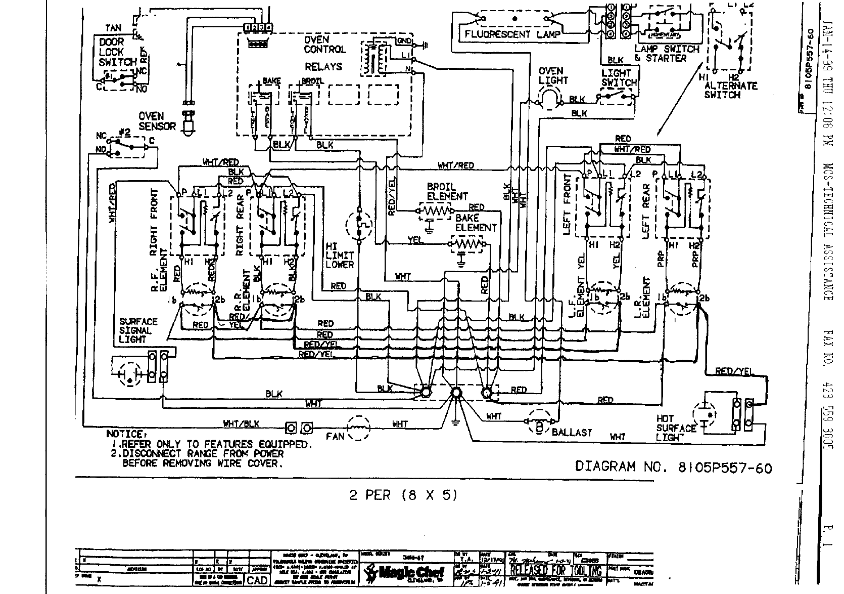
OVEN • FLUORESCENT
CONTROL
RELAYS OVEN
LIGHI
BLK
LIGHT
r_
i=I
.I
!
I
J
ALTERNATE
SWITCH
I
I
I
J
WHT/BL}( _ /-"
NOTICEr FAN ',,_-'
I.REFER ONLY TO FEATURES EOUIPPED,
2.D2SCONNECT RANGE FROM POWER
BEFORE REMOVING WI_ COVER,
WHT wH'r /-\ HOT _. ol
SURFACE'
BALLAST WHT LIGHT
DIAGRAM NO, 8t05P557-60
2 PER (8 X 5)
o
°

