Kenwood USA 229900 800/900MHz Transceiver User Manual Manual
Kenwood USA Corporation 800/900MHz Transceiver Manual
UserManual.wiki
>
Kenwood USA
>
229900 User Manual
>
Manual
Contents
1.
Manual
2.
Manual rf exp statements
Manual
Navigation menu
Upload a User Manual
Namespaces
Wiki Guide
HTML
PDF
Info
Views
User Manual
Discussion / Help
Navigation

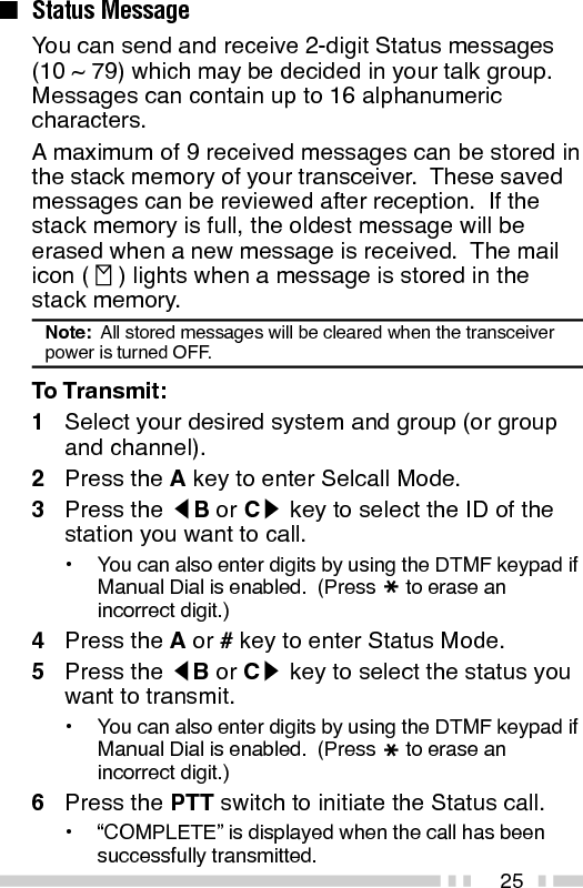
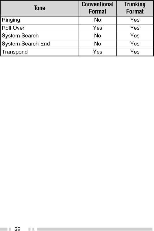
![31AUDIBLE USER FEEDBACK TONESThe transceiver emits various tones to indicate thetransceiver’s operating status. Contact your dealer forfurther information on these tones.enoT lanoitnevnoCtamroFgniknurTtamroFtrelAseYseYysuBseYseYnODBDseYseYffODBDseYseYyaleDoNseYyneDoNseY/edoMkcaBgniRmetsySeerFedoMhcraeSmetsyS oNseYllaCpuorGseYseYllaClaudividnIseYseYtpecretnIoNseYrorrEtupnIyeKseYseY]A[sserPyeKseYseY]B[sserPyeKseYseY]C[sserPyeKseYseYtnemeergAdrowssaPseYseYNOrewoPseYseYtrelAerPseYoNdeecorPoNseYesaeleRTTPseYseYeueuQoNseY](https://usermanual.wiki/Kenwood-USA/229900.Manual/User-Guide-1233283-Page-36.png)