Kenwood USA 229900 800/900MHz Transceiver User Manual Manual
Kenwood USA Corporation 800/900MHz Transceiver Manual
Contents
- 1. Manual
- 2. Manual rf exp statements
Manual

© B62-1483-10 (K, K2, K3, K4)
09 08 07 06 05 04 03 02 01
INSTRUCTION MANUAL
VHF FM TRANSCEIVER/
UHF FM TRANSCEIVER
TK-280/ TK-380
800 MHz FM TRANSCEIVER/
900 MHz FM TRANSCEIVER
TK-480/ TK-481
i
THANK YOU
We are grateful you chose KENWOOD for your land
mobile radio applications. We believe this easy-to-use
transceiver will provide dependable communications to
keep personnel operating at peak efficiency.
KENWOOD transceivers incorporate the latest in
advanced technology. As a result, we feel strongly that
you will be pleased with the quality and features of this
product.
MODELS COVERED BY THIS MANUAL
• TK-280: VHF FM Transceiver
• TK-380: UHF FM Transceiver
• TK-480: 800 MHz FM Transceiver
• TK-481: 900 MHz FM Transceiver
NOTICES TO THE USER
◆Government law prohibits the operation of unlicensed radio
transmitters within the territories under government control.
◆Illegal operation is punishable by fine and/or imprisonment.
◆Refer service to qualified technicians only.
SAFETY: It is important that the operator is aware of
and understands hazards common to the operation of
any transceiver.
EXPLOSIVE ATMOSPHERES (GASES, DUST, FUMES, etc.)
Turn off your transceiver while taking on fuel, or while parked in
gasoline service stations.

ii
One or more of the following statements may be applicable:
FCC WARNING
This equipment generates or uses radio frequency energy. Changes
or modifications to this equipment may cause harmful interference
unless the modifications are expressly approved in the instruction
manual. The user could lose the authority to operate this equipment
if an unauthorized change or modification is made.
INFORMATION TO THE DIGITAL DEVICE USER REQUIRED BY THE FCC
This equipment has been tested and found to comply with the limits
for a Class B digital device, pursuant to Part 15 of the FCC Rules.
These limits are designed to provide reasonable protection against
harmful interference in a residential installation.
This equipment generates, uses and can generate radio frequency
energy and, if not installed and used in accordance with the
instructions, may cause harmful interference to radio communications.
However, there is no guarantee that the interference will not occur in a
particular installation. If this equipment does cause harmful
interference to radio or television reception, which can be determined
by turning the equipment off and on, the user is encouraged to try to
correct the interference by one or more of the following measures:
•Reorient or relocate the receiving antenna.
•Increase the separation between the equipment and receiver.
•Connect the equipment to an outlet on a circuit different from that
to which the receiver is connected.
•Consult the dealer for technical assistance.
ATTENTION (U.S.A. Only):
The RBRC Recycle seal found on KENWOOD nickel-
cadmium (Ni-Cd) battery packs indicates KENWOOD’s
voluntary participation in an industry program to collect
and recycle Ni-Cd batteries after their operating life has
expired. The RBRC program is an alternative to
disposing Ni-Cd batteries with your regular refuse or in
municipal waste streams, which is illegal in some areas.
For information on Ni-Cd battery recycling in your area, call (toll free)
1-800-8-BATTERY (1-800-822-8837).
KENWOOD’s involvement in this program is part of our commitment to
preserve our environment and conserve our natural resources.

iii
CONTENTS
UNPACKING AND CHECKING EQUIPMENT................... 1
Supplied Accessories ...................................... 1
PREPARATION .................................................. 2
Installing/ Removing the Battery Pack ..................... 2
Installing the Antenna ..................................... 3
Installing the Belt Clip ..................................... 3
Installing the Cover over the Universal Connector ..... 4
Installing the (Optional KMC-25) Speaker/ Microphone ... 4
GETTING ACQUAINTED ........................................ 5
Display ...................................................... 7
PROGRAMMABLE AUXILIARY FUNCTIONS ................. 8
OPERATION OVERVIEW .......................................10
Trunking Format ...........................................10
Conventional Format (TK-280/ TK-380 Only) .......... 10
OPERATING BASICS ...........................................11
Switching Power ON/ OFF ................................11
Adjusting the Volume .....................................11
Selecting a System/ Group/ Channel ...................11
Time-out Timer (TOT) ....................................12
TRUNKED OPERATION (Trunking Format) ..................13
Placing a Dispatch Call ..................................13
Receiving a Dispatch Call ................................13
Placing a Telephone Call (Keypad Models Only) ......14
Receiving a Telephone Call (Keypad Models Only) ... 14
CONVENTIONAL OPERATION (Trunking Format) ...........15
Transmitting ...............................................15

iv
Receiving ..................................................15
SYSTEM SCAN (Trunking Format) ...........................16
Scanning Trunked Systems ..............................16
Scanning Conventional Systems ........................16
Scan Lockout ..............................................17
Scan Revert ................................................17
GROUP SCAN (Trunking Format) ............................18
CONVENTIONAL OPERATION (Conventional Format) ..... 19
Transmitting ...............................................19
Receiving ..................................................19
SCAN (Conventional Format) ................................20
Priority Scan ...............................................20
2-TONE SIGNALLING (Conventional Format) ..............21
FleetSync™: ALPHANUMERIC 2-WAY PAGING FUNCTION ... 22
Key Functions .............................................22
Selcall (Selective Calling) ...............................23
Status Message ...........................................25
Optional Short Messages Feature ......................27
DTMF (DUAL TONE MULTI FREQUENCY) CALLS ..........28
Making a DTMF Call (Keypad Models Only) ........... 28
DTMF Signalling ..........................................30
DBD (Dead Beat Disable) ................................30
AUDIBLE USER FEEDBACK TONES ..........................31
1
UNPACKING AND CHECKING EQUIPMENT
Note: The following unpacking instructions are for use by your
KENWOOD dealer, an authorized KENWOOD service facility, or the
factory.
Carefully unpack the transceiver. We recommend that
you identify the items listed in the following table before
discarding the packing material. If any items are missing
or have been damaged during shipment, file a claim with
the carrier immediately.
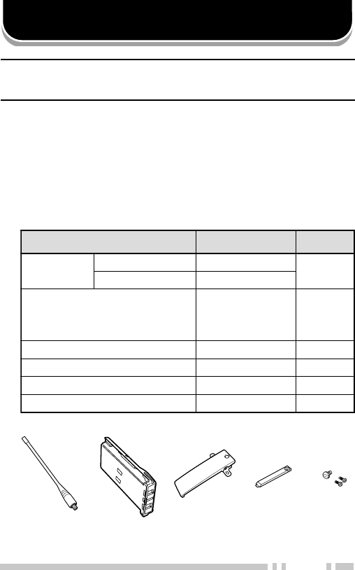
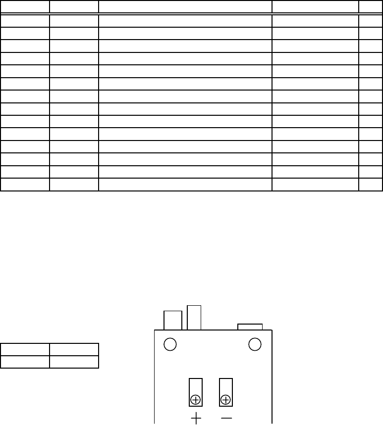
■Supplied Accessories
metI rebmuNtraP ytitnauQ
annetnA 084-KTXX-6360-09T 1
184-KTXX-0460-09T
iN- kcapyrettabdC
2K,K184-KT/084-KT(
)ylnosepyt
XX-0090-90W1
pilctleBXX-8560-92J1
pacrotcennoclarevinUXX-3630-90B1
teswercSXX-4002-99N1
launamnoitcurtsnIXX-3841-26B1
Antenna Ni-Cd battery
pack
Belt
clip Screw
set
Universal
connector cap
2
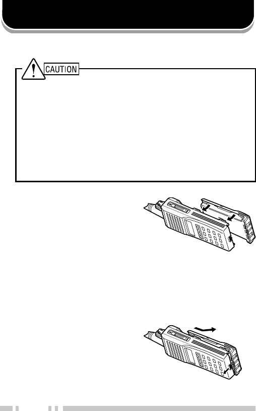
PREPARATION
1Match the four grooves
of the battery pack with
the corresponding
guides on the back of
the transceiver.
2Slide the battery pack
along the back of the
transceiver until the
release latch on the
base of the transceiver
locks.
3To remove the battery
pack, pull back on the
release latch and slide
the pack away from the
transceiver.
■Installing/ Removing the Battery Pack
◆Do not recharge the battery pack if it is already fully charged.
Doing so may cause the life of the battery pack to shorten or
the battery pack may be damaged.
◆After recharging the battery pack, disconnect it from the
charger. If the charger power is reset (turned on after being
turned off), recharging will start again and the battery pack
will become overcharged.
◆Do not short the battery terminals or dispose of the battery
by fire.
◆Never attempt to remove the casing from the battery pack.
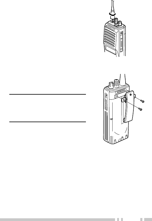
3
Screw the antenna into the
connector on the top of the
transceiver by holding the
antenna at its base and
turning it clockwise until
secure.
■Installing the Belt Clip
If necessary, attach the belt
clip using the two supplied
3 x 6 mm screws.
Note: If the belt clip is not
installed, its mounting location
may get hot during continuous
transmission or when left sitting
in a hot environment.
■Installing the Antenna
4
If you are not using the
optional KMC-25 speaker/
microphone, install the
cover over the univeral
connector using the
supplied 4 x 6 mm screw.
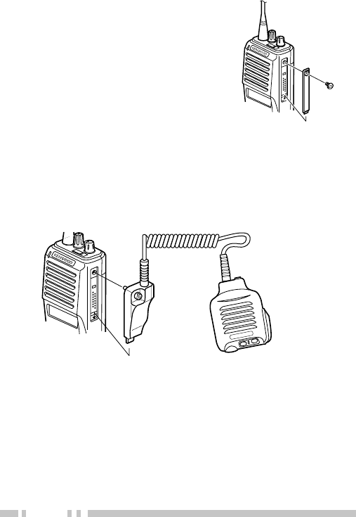
■Installing the Cover over the Universal Connector
■Installing the (Optional KMC-25) Speaker/ Microphone
1Insert the guide of the speaker/ microphone
connector into the groove of the universal
connector.
2Secure the connector in place using the attached
screw.
5
eqw
r
t
o
!2
!0
!1
i
u
y
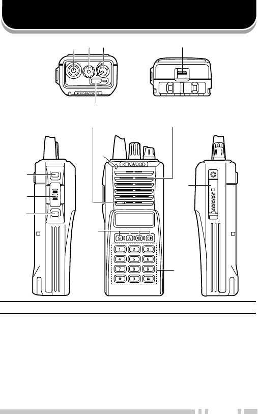
GETTING ACQUAINTED
Note: The transceiver is also available without the DTMF keypad (!1).
qq
qq
qAntenna connector
Connect an antenna here.
ww
ww
wRotary encoder
Rotate this encoder to activate its programmable
function. (System or Group Up/ Down in Trunking
Format, and Group or Channel Up/ Down in
Conventional Format.) For further details, contact
your dealer.
Microphone Speaker

6
ee
ee
ePOWER switch/ VOLUME control
Turn clockwise to switch ON the transceiver. Rotate
to adjust the volume. Turn counterclockwise fully to
switch OFF the transceiver.
rr
rr
rAuxiliary (orange) key
Press to activate its auxiliary function {page 8}.
tt
tt
tBattery pack release latch
Pull back on this latch to release the battery pack.
See “Installing/ Removing the Battery Pack” on page
2.
yy
yy
yPF (Programmable Function) key
Press to activate its auxiliary function {page 8}.
uu
uu
uPTT (Push-To-Talk) switch
Press this switch, then speak into the microphone to
call a station.
ii
ii
iPF (Programmable Function) key
Press to activate its auxiliary function {page 8}.
oo
oo
oTransmit/ Battery low indicator
This red LED lights during transmission. If
programmed by your dealer, when the battery pack
power is low, the LED flashes during transmission.
Replace or recharge the battery pack.
!0!0
!0!0
!0 S, A, tt
tt
tB, and Css
ss
s keys
Press to activate their auxiliary functions {page 8}.
!1!1
!1!1
!1 DTMF keypad (keypad models only)
Press the keys on the keypad to send DTMF tones.
!2!2
!2!2
!2 Universal connector
Connect the (optional KMC-25) speaker/ microphone
here. Otherwise, keep the supplied cover in place.
7
■Display
SVC
MON SCN LO
rotacidnI noitpircseD
.srebmunpuorgdna,lennahc,metsysehtsyalpsiD
neebevahhcihwsnoitcnufsuoiravsyalpsidoslA
.relaedruoyybdemmargorp
silennahcdetcelesehtnehwsraeppA
.ytiroirpsademmargorp
sademmargorpyekehtnehwsraeppA rotinoM si
.desserp
.reviecsnartsihtnodesutonsinocisihT
.edomnacSgnisuerauoynehwsraeppA
sademmargorpyekehtnehwsraeppA rewoPFR
oL .desserpsi
detcelesehtnehwsraeppa,tamroFgniknurTnI
nI.sDIenohpeletsademmargorpsipuorg
gnisuerauoynehwsraeppa,tamroFlanoitnevnoC
.noitcnufenoTelbatceleSrotarepOeht
sthgiL.egassemaevieceruoynehwsehsalF
.yromemkcatsehtniderotssiegassemanehw
.srebmunlennahcdna,puorg,metsysehtsyalpsiD
dna,puorg,metsysmargorpnacrelaedruoY
ecalpni,sretcarahc01otpuhtiwsemanlennahc
asadesusiyalpsidtsomtfelehT.srebmunfo
ddanadnatamroFgniknurTni)(rotacidnieteled
thgirehT.tamroFlanoitnevnoCni)(rotacidni
ro)(llaCevitceleSehtrofdesusiyalpsidtsom
(relbmarcS _srotacidnidda/eteledehT.noitcnuf)
ton/dekcoleratahtslennahc/smetsysehtwohs
evitceleS.ecneuqesgninnacsehtfotuodekcol
nactahtsnoitcnuflanoitpoerarelbmarcSdnallaC
syalpsidoslA.relaedruoyybdemmargorpeb
cnySteelFgnisunehwsegassemdeviecer .
MON
SVC
SCN
LO

8
PROGRAMMABLE AUXILIARY FUNCTIONS
Keys r, y, i, and !0 {pages 5 and 6} can be programmed
with the auxiliary functions listed in the following table. The
programmable functions are dependant on the operation of
the transceiver (Conventional or Trunking Format). Contact
your dealer for further details on these functions.
Note:
◆If “Function” is programmed onto a key, the DTMF keypad (keypad
models only) can also be used for additional programmable keys.
◆Conventional Format is available for only the TK-280 and TK-380
models.
noitcnuF lanoitnevnoC
tamroF
gniknurT
tamroF
leTotuAoNseY
XUA
1
seYseY
nwoDlennahCseYoN
pUlennahCseYoN
)TOB(DIFMTDseYseY
)TOE(DIFMTDseYseY
retcarahCyalpsiDseYseY
ycnegremE
2
seYseY
noitcnuFseYseY
nwoDpuorGseYseY
pUpuorGseYseY
lennahCemoHseYoN
puorGemoHoNseY
kcoLyeKseYseY
pmaLseYseY
)OTS/LCR(yromeMseYseY
)LCR(yromeMseYseY
)OTS(yromeMseYseY

9
noitcnuF lanoitnevnoC
tamroF
gniknurT
tamroF
edoMegasseMseYseY
rotinoM(ArotinoM
))yratnemoM(etumnU seYseY
rotinoM(BrotinoM
))elggoT(etumnU seYseY
reirraC(CrotinoM
))yratnemoM(hcleuqS seYseY
reirraC(DrotinoM
))elggoT(hcleuqS seYseY
enoTleSrotarepOseYoN
laideRseYseY
oLrewoPFRseYseY
nacSseYseY
ddA/leDnacSseYseY
eteleDyraropmeTnacSoNseY
SPGdneS
3
seYseY
noitaunettAPS
4
seYseY
nwoDmetsySoNseY
pUmetsySoNseY
relbmarcS
5
seYseY
dnuorAklaTseYoN
tcennocsiDLEToNseY
1This function can be selected only when the Scrambler/ ANI board
has not been installed.
2This function can be programmed only on key r, the Auxiliary
(orange) key.
3This function can be selected only when the FleetSync™ enhanced
option and a GPS receiver have been installed.
4This function can be programmed only on the microphone PF keys.
5This function can be selected only when the Scrambler board has
been installed.

10
OPERATION OVERVIEW
Your dealer can program your transceiver for either
Trunking Format or Conventional Format.
■Trunking Format
This format can handle up to 32 systems with up to
250 groups in each system. The transceiver can be
used in both trunked mode and conventional mode.
Systems, groups, and their functions are
programmed by your dealer.
■Conventional Format (TK-280/ TK-380 Only)
This format can handle up to 250 groups with 250
channels in each group. The transceiver can be
used only in conventional mode. Groups, channels,
and their functions are programmed by your dealer.

11
OPERATING BASICS
■Switching Power ON/ OFF
Turn the Power switch/ Volume control clockwise to
switch the transceiver ON.
Turn the Power switch/ Volume control
counterclockwise to switch the transceiver OFF.
If the Radio Password function is programmed,
“PASSWORD” will appear on the display when the
power is turned ON. To unlock the transceiver, enter
the password, then press the S key. If you enter the
wrong password, an error tone sounds and the
transceiver remains locked. The password can
contain a maximum of 6 digits.
■Adjusting the Volume
Rotate the Power switch/ Volume control to adjust
the volume. Clockwise increases the volume and
counterclockwise decreases it.
■Selecting a System/ Group/ Channel
Select the desired system and group (Trunking
Format) using the encoder and the keys programmed
with System or Group Up/ Down.
Select the desired group and channel (Conventional
Format) using the encoder and the keys programmed
with Group or Channel Up/ Down.

12
■Time-out Timer (TOT)
The purpose of the Time-out Timer is to prevent any
caller from using a channel for an extended period of
time.
If you continuously transmit for a period of time that
exceeds the programmed time, the transceiver will
stop transmitting and an alert tone will sound. To
stop the tone, release the PTT switch.
Your dealer can program the TOT time in the range of
15 seconds to 10 minutes.

13
TRUNKED OPERATION (Trunking Format)
■Placing a Dispatch Call
1Select the desired system and group using the
encoder and the System or Group keys.
2Press the PTT switch.
3If a tone does not sound, communication is
possible; start speaking into the microphone.
Release the PTT switch to receive.
•For best sound quality at the receiving station, hold
the microphone approximately 1.5 inches (3 ~ 4 cm)
from your mouth.
■Receiving a Dispatch Call
1Select the desired system and group using the
encoder and the System or Group keys. (If the
Scan function has been programmed, you can
switch it ON or OFF as desired.)
2When you hear the dispatcher’s voice, readjust
the volume as necessary.

14
■Placing a Telephone Call (Keypad Models Only)
1Select the desired system and group using the
encoder and the System or Group keys.
2Press and hold the PTT switch for approximately
1 second to ensure a connection.
•Confirm that there is a dial tone after you release the
PTT switch.
3Press and hold the PTT switch, then dial using
the front panel keypad.
•After dialing, release the PTT switch and wait for a
response from the called party.
4When the called party responds, press the PTT
switch and speak into the microphone. Release
the PTT switch to receive.
•Only one person can speak at a time.
5To end the call, press and hold the PTT switch,
then press the # key or the key programmed as
Tel Disconnect.
■Receiving a Telephone Call (Keypad Models Only)
1Select the desired system and group using the
encoder and the System or Group keys. (If the
Scan function has been programmed, you can
switch it ON or OFF as desired.)
•A ringing tone will sound when a call is received.
2Press and hold the PTT switch to speak, and
release it to receive.
•Only one person can speak at a time.
3To end the call, press and hold the PTT switch,
then press the # key or the key programmed as
Tel Disconnect.

15
CONVENTIONAL OPERATION (Trunking Format)
■Transmitting
1Select the desired system and group using the
encoder and the System or Group keys.
2Press the key programmed as Monitor to check
whether or not the channel is free.
•If the channel is busy, wait until it becomes free.
3Press the PTT switch and speak into the
microphone. Release the PTT switch to receive.
•For best sound quality at the receiving station, hold
the microphone approximately 1.5 inches (3 ~ 4 cm)
from your mouth.
■Receiving
1Select the desired system and group using the
encoder and the System or Group keys. (If the
Scan function has been programmed, you can
switch it ON or OFF as desired.)
2When you hear the dispatcher’s voice, readjust
the volume as necessary.

16
SYSTEM SCAN (Trunking Format)
If the Scan function is programmed, systems can be
scanned by pressing the key programmed as Scan.
When the Scan key is pressed, the SCN indicator and
“-SCAN-” or the revert system/ group number, appear on
the display and scanning starts. The systems not locked
out of the scanning sequence are scanned.
When a call is received, scanning stops and the system
and group digits appear. Press the PTT switch and
speak into the microphone to respond to the call. The
transceiver will continue scanning after a predetermined
time delay if the PTT switch is released and no further
signal is received.
■Scanning Trunked Systems
When scanning trunked systems, the revert groups
and the groups not locked out of the scanning
sequence are scanned. See “GROUP SCAN” on
page 18.
■Scanning Conventional Systems
When scanning conventional systems, the revert
groups and the groups not locked out of the scanning
sequence are scanned. See “GROUP SCAN” on
page 18.

17
■Scan Lockout
If a programmable auxiliary key is programmed with
Scan Del/Add, each system can be locked out of the
scan sequence manually. The delete indicator ( s )
will appear on the display when the selected system
is locked out.
■Scan Revert
You can select revert systems and groups using the
encoder and the System or Group keys.
Four types of Scan Reverts which can be
programmed by your dealer are available:
•Last Called Revert: The last system/ group
received is assigned as the new revert system
and group.
•Last Used Revert: The last system/ group
responded to is assigned as the new revert
system and group.
•Selected: The last system/ group selected is
assigned as the new revert system and group.
•Selected + Talkback: If the system/ group has
been changed during Scan, the newly selected
system/ group is assigned as the new revert
system and group. The transceiver “talks back”
on the current receive group.

18
GROUP SCAN (Trunking Format)
Group Scan is available for both trunked and
conventional systems. This feature is useful when more
than one group is programmed in a system. Group
Scan is set by your dealer on request. It scans the
revert groups as well as groups that are allowed to be
scanned.
When a call is received, the group indicator shows the
group number, and that group becomes the revert
group. Simply press the PTT switch to respond to the
call.
You can also perform Group Scan while using a priority
channel. Please contact your dealer for information
concerning Priority Scan.

19
CONVENTIONAL OPERATION (Conventional Format)
■Transmitting
1Select the desired group and channel using the
encoder and the Group or Channel keys.
2Press the key programmed as Monitor to check
whether or not the channel is free.
•If the channel is busy, wait until it becomes free.
3Press the PTT switch and speak into the
microphone. Release the PTT switch to receive.
•For best sound quality at the receiving station, hold
the microphone approximately 1.5 inches (3 ~ 4 cm)
from your mouth.
■Receiving
1Select the desired group and channel using the
encoder and the Group or Channel keys. (If the
Scan function has been programmed, you can
switch it ON or OFF as desired.)
2When you hear a caller’s voice, readjust the
volume as necessary.

20
SCAN (Conventional Format)
If the Scan function is programmed, groups or channels
can be scanned by pressing the key programmed as
Scan. Scan can be used as either Single Scan or Multi
Scan. Single Scan monitors only the channels of a
single group. Multi Scan monitors all channels of every
group. When the Scan key is pressed, the SCN
indicator and “-SCAN-” or the revert group/ channel
number, appear on the display and scanning starts.
When a call is received, scanning stops and the group
and channel digits appear. Press the PTT switch and
speak into the microphone to respond to the call. The
transceiver will continue scanning after an adjustable
time delay, if the PTT switch is released, and no further
signal is received.
When the displayed group is not locked out of the
scanning sequence, the add indicator ( ) will appear on
the display.
■Priority Scan
The priority channel must be programmed in order
for Priority Scan to function.
The transceiver will automatically change to the
priority channel when a signal is received on it, even
if a signal is being received on a normal channel.
The indicator appears when the displayed channel
is the priority channel.

21
2-TONE SIGNALLING (Conventional Format)
2-Tone Signalling is either activated or deactivated by
your dealer.
2-Tone Signalling only opens the squelch when the
transceiver receives two tones corresponding to those
set up in the transceiver. When the squelch opens, you
will be able to hear the caller without any further action.
After a correct 2-Tone signal is received and the squelch
opens, pressing the key programmed as Monitor will
cancel the connection.
If your dealer programmed Transpond for 2-Tone
Signalling, your transceiver will automatically send an
acknowledgment signal to the station that called you
with the correct 2-Tone signal. Transpond does not
function when you are called as a Group call.
If your dealer programmed Tone Alert for 2-Tone
Signalling, your transceiver will emit a beep when the
correct 2-Tone signal is received.
Note: This transceiver is only capable of decoding 2-Tone Signals. It
cannot encode a 2-Tone Signal.
22
FleetSync™ is an Alphanumeric 2-way Paging Function,
and is a protocol owned by KENWOOD Corporation.
FleetSync™ enables a variety of paging functions on
your transceiver, some of which depend on dealer
programming.
■Key Functions
FleetSync™: ALPHANUMERIC 2-WAY PAGING FUNCTION
Selcall Mode 1
Status Mode
Stack Mode
New Message
Display Mode
Normal Operating Mode
Press A
or receive
a Selcall
Receive
a new
message
Hold A for
1 second
Press
any key
Press
A or #
Press
A or #
Press
A or #
Hold A or # for 1 second
yeK noitcnuF
A,#
ninwohssaedomreviecsnartehtegnahcotsserP
ehT(.wolebmargaideht #noelbaliavasiyek
.)ylnosledomdapyek
S
ehtneewtebelggototedoMkcatSnielihwsserP
dnasserP.DIs’rellacehtdnaegassemdeviecer
deyalpsidehteteledotdnoces1nahteromrofdloh
.egassem
tt
t
ttB,Css
s
ss atcelesotedomsutatSrollacleSnielihwsserP
.sutatsreviecsnartruoyroDInoitats
TTP .llacaetaitiniotsserP
FMTD(
)dapyeK
sutatSrollacleSretneotdapyekFMTDehtesU
.)ylnosledomdapyek(srebmun
1Depending on how your dealer programmed the transceiver,
Selcall Mode may be skipped or the transceiver may exit Selcall
Mode automatically (as shown by the dash arrow).

23
■Selcall (Selective Calling)
A Selcall is a voice call to a particular station or to a
group of stations.
To Transmit:
1Select your desired system and group (or group
and channel).
2Press the A key to enter Selcall Mode.
3Press the tB or Cs key to select the ID of the
station you want to call.
•You can also enter digits by using the DTMF keypad if
Manual Dial is enabled. (Press to erase an
incorrect digit.)
4Press the PTT switch and begin your
conversation.
To Receive:
An alert tone will sound, the transceiver will
automatically enter Selcall Mode, and the calling
station’s ID will appear when a Selcall is received.
To respond to the call, press the PTT switch and

24
To View the Caller IDs in the Stack Memory:
The mail icon ( ) will flash when a Selcall call is
received and stacked.
1Press and hold the A key for more than 1 second
to enter Stack Mode.
•The last received Caller ID is displayed with the Caller
ID number. “I” (ID) appears with the number.
2Press the tB or Cs key to select the ID you
want to view (if more than one ID is stored in the
stack memory).
3To erase the ID, press and hold the S key for
more than 1 second.
Identification Codes:
An ID code is a combination of a 3-digit Fleet
number and a 4-digit ID number. Each transceiver
must have its own Fleet and ID number.
•Enter a Fleet number (100 ~ 349) to make a group call.
•Enter an ID number (1000 ~ 4999) to make an individual
call in your fleet.
•Enter a Fleet number followed by an ID number to make
an individual call in your desired fleet (Inter-fleet call).
•Select “ALL” Fleet and “ALL” ID to make a call to all units
(Broadcast call).
•Select “ALL” Fleet and enter an ID number to make a call
to the selected ID in all fleets (Supervisor call).
Note:
◆Broadcast and Supervisor calls are programmed functions
that cannot be made with a keypad.
◆The ID range may be limited by programming.

25
■Status Message
You can send and receive 2-digit Status messages
(10 ~ 79) which may be decided in your talk group.
Messages can contain up to 16 alphanumeric
characters.
A maximum of 9 received messages can be stored in
the stack memory of your transceiver. These saved
messages can be reviewed after reception. If the
stack memory is full, the oldest message will be
erased when a new message is received. The mail
icon ( ) lights when a message is stored in the
stack memory.
Note: All stored messages will be cleared when the transceiver
power is turned OFF.
To Transmit:
1Select your desired system and group (or group
and channel).
2Press the A key to enter Selcall Mode.
3Press the tB or Cs key to select the ID of the
station you want to call.
•You can also enter digits by using the DTMF keypad if
Manual Dial is enabled. (Press to erase an
incorrect digit.)
4Press the A or # key to enter Status Mode.
5Press the tB or Cs key to select the status you
want to transmit.
•You can also enter digits by using the DTMF keypad if
Manual Dial is enabled. (Press to erase an
incorrect digit.)
6Press the PTT switch to initiate the Status call.
•“COMPLETE” is displayed when the call has been
successfully transmitted.

26
To Receive:
The mail icon ( ) will flash and a calling ID or text
message will appear when a Status call is received.
•The display alternates between the caller ID and the
message.
Press any key to return to Normal Operation Mode.
To Review the Messages in the Stack Memory:
1Press and hold the A key for more than 1 second
to enter Stack Mode.
•The last received message is displayed with the
message number. “S” (Status) appears with the
number.
2Press the tB or Cs key to select the message
you want to view (if more than one message is
stored in the stack memory).
3Press the S key to toggle between the message
and the caller’s ID.
4To erase the message, press and hold the S key
for more than 1 second.
Automatic Status Response:
If you pre-select a status number and then leave the
transceier in Status Mode, the transceiver will
automatically respond with that status number when
a request from the base station is received. (The
base station request function is optional.)

27
■Optional Short Messages Feature
Received short messages (maximum of 48
characters) are displayed the same as Status
messages {page 24}, however only 4 short
messages can be stored in the stack memory. “M”
(Message) and the message number appear with the
message.

28
DTMF (DUAL TONE MULTI FREQUENCY) CALLS
■Making a DTMF Call (Keypad Models Only)
There are two methods of making a DTMF call:
•Manual dialing
•Store and sending
To make a call by dialing manually:
1Press and hold the PTT switch.
2Enter the desired digits using the front panel
keypad.
•The corresponding DTMF tones sound each time you
press a key.
•If you release the PTT switch, transmit mode will end
even if the complete number has not been sent.
•If your dealer has activated the Keypad Auto PTT
function, you need not hold down the PTT switch
while pressing the keys on the keypad in Conventional
systems. The DTMF code will be sent automatically
when you press a key.
Note: Keypad Auto PTT does not function in Trunking systems.

29
To make a call by storing and sending:
1Enter the desired digits using the front panel
keypad.
•The digits appear on the display as you enter them.
2After entering the complete number, press the
PTT switch.
•If you are using the transceiver in a Conventional
system, the DTMF code is transmitted after pressing
the PTT switch.
•If you are using the transceiver in a Trunking system,
the DTMF code is transmitted after a connection is
established. Releasing the PTT switch before a
connection is established will stop the transmission
from occuring.
•If you are using the transceiver in a RIC (Repeater
Inter-Connect) Trunking system, the DTMF code is
transmitted after a connection with the telephone
system is established. If you press the key
programmed as Auto Tel instead of the PTT switch,
the call will automatically connect to the repeater, and
the DTMF code will be transmitted.
Note:
◆You can only store up to 16 digits before sending. Entering
more than 16 digits will cause an error tone to sound.
◆If you switch the power OFF before sending the number, the
number will be cleared from memory.

30
■DTMF Signalling
Your dealer can program a group with a DTMF
signalling code. When you receive a call with a code
that matches yours, the signalling indicator will flash
and a tone will sound. Squelch opens and you will
hear the call.
Squelch will close when you receive a call with a
code that matches your signalling reset code.
When making a call on a group programmed with a
DTMF signalling code, the signalling indicator will
light and the squelch will open.
■DBD (Dead Beat Disable)
Depending on how your dealer programs your
transceiver, when you receive a call containing a
DBD code, either transmit mode or receive and
transmit modes will be disabled. When a DBD code
is received, a tone will sound.
DBD is cancelled when you receive a call with a DBD
cancel code.

31
AUDIBLE USER FEEDBACK TONES
The transceiver emits various tones to indicate the
transceiver’s operating status. Contact your dealer for
further information on these tones.
enoT lanoitnevnoC
tamroF
gniknurT
tamroF
trelAseYseY
ysuBseYseY
nODBDseYseY
ffODBDseYseY
yaleDoNseY
yneDoNseY
/edoMkcaBgniRmetsySeerF
edoMhcraeSmetsyS oNseY
llaCpuorGseYseY
llaClaudividnIseYseY
tpecretnIoNseY
rorrEtupnIyeKseYseY
]A[sserPyeKseYseY
]B[sserPyeKseYseY
]C[sserPyeKseYseY
tnemeergAdrowssaPseYseY
NOrewoPseYseY
trelAerPseYoN
deecorPoNseY
esaeleRTTPseYseY
eueuQoNseY

32
enoT lanoitnevnoC
tamroF
gniknurT
tamroF
gnigniRoNseY
revOlloRseYseY
hcraeSmetsySoNseY
dnEhcraeSmetsySoNseY
dnopsnarTseYseY
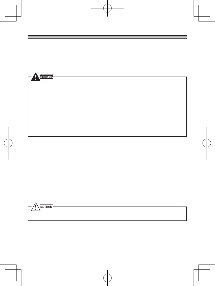
TK-481 Terminal Descriptions
Universal connector
It is possible to use a resin-based cover for the Universal connector.
NO. Name Description Impedance I/O
1 SSW Ext/Int Speaker Switch Input High Impedance I
2 SP+ BTL Output + for External Speaker 8 ΩO
3 SP- BTL Output - for External Speaker 16 ΩO
4 MSW Ext/Int MIC Switch Input High Impedance I
5 EMC External MIC Input 1.8 kΩI
6 ME External MIC GND GND -
7 PTT External PTT Input High Impedance I
8 PF Programable Function Key Input High Impedance I
9 NC Not used - -
10 E GND GND -
11 5M 5V power supply output 5V -
12 TXD Serial Data Output CMOS O
13 RXD Serial Data Input CMOS I
14 NC Not used - -
Antenna Terminal
50 Ω impedance
Battery Terminal
The battery terminal uses a spring plate.
The negative terminal connects to the chassis ground.
The battery is mounted on the rear and upper side of the transceiver using a
sliding mounting method.
1+
2- 12
Back side view
Antena
Radio FRequency eneRgy SaFety inFoRmation
This Kenwood transceiver has been tested and complies with the standards listed below, in regards
to Radio Frequency (RF) energy and electromagnetic energy (EME) generated by the transceiver.
• FCC RF exposure limits for
Occupational Use Only
. RF Exposure limits adopted by the FCC are generally
based on recommendations from the National Council on Radiation Protection and Measurements, & the
American National Standards Institute.
• FCC OET Bulletin 65 Edition 97-01 Supplement C
• American National Standards Institute (C95.1 – 1992)
• American National Standards Institute (C95.3 – 1992)
This Kenwood transceiver generates RF EME while transmitting. RF EME (Radio Frequency Electric &
Magnetic Energy) has the potential to cause slight thermal, or heating effects to any part of your body less
than the recommended distance from this radio transmitter’s antenna. RF energy exposure is determined
primarily by the distance to and the power of the transmitting device. In general, RF exposure is minimized
when the lowest possible power is used or transmission time is kept to the minimum required for consistent
communications, and the greatest distance possible from the antenna to the body is maintained. The
transceiver has been designed for and is classied for
Occupational Use Only
. Occupational/ controlled
exposure limits are applicable to situations in which persons are exposed to RF energy as a consequence
of their employment, and such persons have been made aware of the potential for exposure and can
exercise control over their exposure. This means you can use the transceiver only if you are aware of
the potential hazards of operating a transceiver and are familiar in ways to minimize these hazards. This
transceiver is not intended for use by the general public in uncontrolled environments. Uncontrolled
environment exposure limits are applicable to situations in which the general public may be exposed to RF
energy, or in which the persons who are exposed as a consequence of their employment may not be fully
aware of the potential for exposure or cannot exercise control over their exposure.
The following list provides you with the information required to ensure that you are aware of RF
exposure and of how to operate this transceiver so that the FCC RF exposure limitations are not
exceeded.
• While transmitting (holding the PTT switch or speaking with VOX enabled), always keep the antenna
and the radio at least 3 cm (1 3/16 inches) from your body or face, as well as from any bystanders. A
LED on the top of the radio shows red when the transmitter is operating in both PTT and VOX modes.
• Do not transmit for more than 50% of the total transceiver use time; transmitting over 50% of the total use
time may exceed the limits in accordance to the FCC RF exposure requirements. Nominal transceiver
operation is 5% transmission time, 5% reception time, and 90% stand-by time.
• Use only the specied antenna for this transceiver; this may be either the antenna provided with the
transceiver or another antenna authorized by Kenwood.
Use only Kenwood authorized accessories (antennas, battery packs, belt clips, Speaker/ Mics or
headsets etc.): When worn on the body, always place the radio in a Kenwood recommended clip or
carrying case meant for this product. The use of other than recommended or approved body- worn
accessories may result in RF exposure levels which exceed the FCC’s occupational/ controlled
environment RF exposure limits.
To ensure that your exposure to RF EME is within the FCC limits for occupational use, you must
observe and adhere to the above points.
Electromagnetic Interference Compatibility
Electronic devices are susceptible to electromagnetic interference (EMI) if they are not adequately
shielded or designed for electromagnetic compatibility. Because this transceiver generates RF
energy, it can cause interference to such equipment.
• Turn OFF your transceiver where signs are posted to do so. Hospitals and health care facilities use
equipment that is sensitive to electromagnetic radiation.
• Turn OFF your transceiver while on board an aircraft when so instructed. Use of the transceiver must
be in accordance with airline regulations and/or crew instructions. B59-2546-00