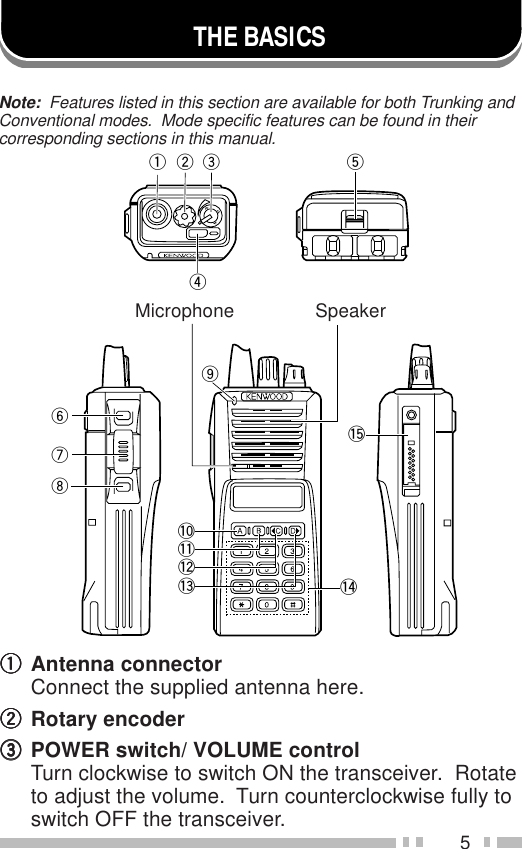
Kenwood USA 29492110 VHF-FM Face Held Transceiver User Manual TK 285 385 E 00 Cover

Kenwood USA Corporation VHF-FM Face Held Transceiver TK 285 385 E 00 Cover

Manual

© B62-1264-00 (K,K3,M,E)09 08 07 06 05 04 03 02 01 00KENWOOD CORPORATIONINSTRUCTION MANUALVHF FM TRANSCEIVERTK-285TK-385UHF FM TRANSCEIVER
EXPLOSIVE ATMOSPHERES (GASES, DUST, FUMES, etc.)Turn off your transceiver while taking on fuel, or while parked ingasoline service stations.◆GOVERNMENT LAW PROHIBITS THE OPERATION OFUNLICENSED RADIO TRANSMITTERS WITHIN THETERRITORIES UNDER GOVERNMENT CONTROL.◆ILLEGAL OPERATION IS PUNISHABLE BY FINE ORIMPRISONMENT OR BOTH.◆REFER SERVICE TO QUALIFIED TECHNICIANS ONLY.SAFETY:  It is important that the operator is aware ofand understands hazards common to the operation ofany transceiver.THANK YOUWe are grateful you chose KENWOOD for your landmobile radio applications.  We believe this easy-to-usetransceiver will provide dependable communications tokeep personnel operating at peak efficiency.KENWOOD transceivers incorporate the latest inadvanced technology.  As a result, we feel strongly thatyou will be pleased with the quality and features of thisproduct.MODELS COVERED BY THIS MANUAL•  TK-285:  VHF FM Transceiver•  TK-385:  UHF FM TransceiverNOTICES TO THE USER
iOne or more of the following statements may beapplicable:FCC WARNINGThis equipment generates or uses radio frequency energy.  Changesor modifications to this equipment may cause harmful interferenceunless the modifications are expressly approved in the instructionmanual.  The user could lose the authority to operate this equipment ifan unauthorized change or modification is made.INFORMATION TO THE DIGITAL DEVICE USER REQUIRED BYTHE FCCThis equipment has been tested and found to comply with the limitsfor a Class B digital device, pursuant to Part 15 of the FCC Rules.These limits are designed to provide reasonable protection againstharmful interference in a residential installation.This equipment generates, uses and can generate radio frequencyenergy and, if not installed and used in accordance with the instructions,may cause harmful interference to radio communications.  However,there is no guarantee that the interference will not occur in a particularinstallation.  If this equipment does cause harmful interference to radioor television reception, which can be determined by turning theequipment off and on, the user is encouraged to try to correct theinterference by one or more of the following measures:•Reorient or relocate the receiving antenna.•Increase the separation between the equipment and receiver.•Connect the equipment to an outlet on a circuit different from thatto which the receiver is connected.•Consult the dealer for technical assistance.ATTENTION (U.S.A. Only):The RBRC Recycle seal found on KENWOODnickel-cadmium (Ni-Cd) battery packs indicatesKENWOOD’s voluntary participation in an industryprogram to collect and recycle Ni-Cd batteries aftertheir operating life has expired.  The RBRC programis an alternative to disposing Ni-Cd batteries withyour regular refuse or in municipal waste streams,which is illegal in some areas.For information on Ni-Cd battery recycling in your area, call (toll free)1-800-8-BATTERY (1-800-822-8837).KENWOOD’s involvement in this program is part of our commitmentto preserve our environment and conserve our natural resources.
iiCONTENTSUNPACKING AND CHECKING EQUIPMENT .............................. 1Supplied Accessories ............................................................. 1PREPARATION ............................................................................ 2Installing/ Removing the (Optional) NiCd Battery Pack ........... 2Installing the Antenna ............................................................. 3Installing the Belt Clip ............................................................. 3Installing the Cover over the Universal Connector .................. 4Installing the (Optional KMC-25) Speaker/ Microphone .......... 4THE BASICS ................................................................................ 5Switching Power ON/ OFF ..................................................... 6Adjusting the Volume .............................................................. 6TRUNKING MODE ....................................................................... 7Key Functions ........................................................................ 7Programmable Auxiliary Functions ......................................... 8Display ................................................................................... 8Searching for a Control Channel ............................................ 9Voice Calls ............................................................................. 9Making a Voice Call ......................................................... 9Receiving a Voice Call ....................................................11Status Calls .......................................................................... 12Making a Status Call ...................................................... 12Receiving a Status/Short Data Message Call ................. 13Call Displays ........................................................................ 13Viewing the Stack ................................................................. 14Call Diversions ..................................................................... 14Diverting Your Own Calls ............................................... 14Diverting Third Party Calls ............................................. 15CONVENTIONAL MODE ............................................................ 16Key Functions ...................................................................... 16Display ................................................................................. 17Entering Conventional Mode ................................................ 17Returning to Trunking Mode ................................................. 18Conventional Mode Operation .............................................. 18Scanning .............................................................................. 19Lamp .................................................................................... 19APPENDIX ................................................................................. 20
1UNPACKING AND CHECKING EQUIPMENTNote:  The following unpacking instructions are for use by your KENWOODdealer, an authorized KENWOOD service facility, or the factory.Carefully unpack the transceiver.  We recommend thatyou identify the items listed in the following table beforediscarding the packing material.  If any items aremissing or have been damaged during shipment, file aclaim with the carrier immediately.Supplied AccessoriesBelt clip Universal connector cap Screw setAntenna (TK-285) Antenna (TK-385)metI rebmuNtraP ytitnauQ)ylnoE(kcapyrettaBXX-0900-90W1annetnA )ylnoE,K(582-KTXX-3370-09T 1)ylnoM(582-KTXX-4370-09TpilctleBXX-8560-92J1pacrotcennoclarevinUXX-3630-90B1teswercSXX-4002-99N1)ylno3K,K(dracytnarraW––1launamnoitcurtsnIXX-4621-26B1
2PREPARATION1Match the four grooves ofthe battery pack with thecorresponding guides onthe back of the transceiver.2Slide the battery pack alongthe back of the transceiveruntil the release latch onthe base of the transceiverlocks.3To remove the battery pack,pull back on the releaselatch and slide the packaway from the transceiver.Installing/ Removing the (Optional) NiCd Battery Pack◆DO NOT RECHARGE THE BATTERY PACK IF IT IS ALREADYFULLY CHARGED.  DOING SO MAY CAUSE THE LIFE OF THEBATTERY PACK TO SHORTEN OR THE BATTERY PACK MAYBE DAMAGED.◆AFTER RECHARGING THE BATTERY PACK, DISCONNECT ITFROM THE CHARGER.  IF THE CHARGER POWER IS RESET(TURNED ON AFTER BEING TURNED OFF), RECHARGINGWILL START AGAIN AND THE BATTERY PACK WILL BECOMEOVERCHARGED.◆DO NOT SHORT THE BATTERY TERMINALS OR DISPOSEOF THE BATTERY BY FIRE.◆NEVER ATTEMPT TO REMOVE THE CASING FROM THEBATTERY PACK.
3Screw the antenna into theconnector on the top of thetransceiver by holding theantenna at its base and turningit clockwise until secure.Installing the Belt ClipIf necessary, attach the belt clipusing the two supplied3 x 6 mm screws.Note:  If the belt clip is not installed, itsmounting location may get hot duringcontinuous transmission or when leftsitting in a hot environment.Installing the Antenna
4If you are not using the optionalKMC-25 speaker/ microphone,install the cover over theuniveral connector using thesupplied 4 x 6 mm screw.Installing the Cover over the Universal ConnectorInstalling the (Optional KMC-25) Speaker/ Microphone1Insert the guide of the speaker/ microphoneconnector into the groove of the universal connector.2Secure the connector in place using the attachedscrew.
5eqwrto!5!0!4iuy!1!2!3THE BASICSMicrophone SpeakerqqqqqAntenna connectorConnect the supplied antenna here.wwwwwRotary encodereeeeePOWER switch/ VOLUME controlTurn clockwise to switch ON the transceiver.  Rotateto adjust the volume.  Turn counterclockwise fully toswitch OFF the transceiver.Note:  Features listed in this section are available for both Trunking andConventional modes.  Mode specific features can be found in theircorresponding sections in this manual.
6rrrrrAuxiliary (orange) keytttttBattery pack release latchPull back on this latch to release the battery pack.See “Installing/ Removing the (Optional) NiCdBattery Pack” on page 2.yyyyyCall keyuuuuuPTT (Push-To-Talk) switchiiiiiClear keyoooooTransmit/ Receive indicator!0!0!0!0!0 A key!1!1!1!1!1 B key!2!2!2!2!2 C key!3!3!3!3!3 D key!4!4!4!4!4 DTMF keypad!5!5!5!5!5 Universal connectorConnect the (optional KMC-25) speaker/ microphonehere.  Otherwise, keep the supplied cover in place.■Switching Power ON/ OFFTurn the Power switch/ Volume control clockwise toswitch the transceiver ON.  The power on text or unitnumber appears for 2 seconds.Turn the Power switch/ Volume controlcounterclockwise to switch the transceiver OFF.■Adjusting the VolumeRotate the Power switch/ Volume control to adjustthe volume.  Clockwise increases the volume andcounterclockwise decreases it.
7Key FunctionsNote:  The numbers correspond to the diagram on page 5.wwwwwRotary encoderRotate this encoder to select your desired calladdress (voice calls) or status (status calls).rrrrrAuxiliary (orange) key (default setting:  None)Press to activate its auxiliary function {page 8}.yyyyyCall keyPress to call the displayed call address.uuuuuPTT (Push-To-Talk) switchPress to transmit.  Also press to initiate a call if “PTTto Initiate Call” has been programmed.iiiiiClear keyPress to end the current call.oooooTransmit indicatorLights red while transmitting.!0!0!0!0!0 A key (default setting:  Status/ Stack)Press to activate its auxiliary function {page 8}.!1!1!1!1!1 B key (default setting:  Redial)Press to activate its auxiliary function {page 8}.!2!2!2!2!2 C key (default setting:  Home)Press to activate its auxiliary function {page 8}.  Alsopress to scroll left while viewing stack entries.!3!3!3!3!3 D key (default setting:  None)Press to activate its auxiliary function {page 8}.  Alsopress to scroll right while viewing stack entries.!4!4!4!4!4 DTMF keypadPress to input a call address or dialing function.TRUNKING MODE
8Programmable Auxiliary FunctionsThe Auxiliary, A, B,  C, and D keys can beprogrammed with the auxiliary functions listed below.Contact your dealer for details on these functions.Note:  Some of these functions cannot be programmed onto certainkeys. Ask your dealer for details.• AUX A • Network Select• Conventional • None• Dialing • Redial• Emergency • Scrambler• Home • Status/ Stack• Key LockDisplaySVCMON SCN LO displays the strength of received signals, theoutput power (high or low), status numbers, andreceived call types.SVC appears when a control channel is found.  It flasheswhile the transceiver is searching for a control channel. flashes when you activate call diversion. appears while there is data in the stack.  It flasheswhen there is new data in the stack. displays call addresses, the callduration timer, data messages, and the currentoperating status of the transceiver.
9Searching for a Control ChannelAfter switching the power ON, press any key while thepower on text or unit number is displayed to beginsearching for a control channel.  Or, wait for2 seconds to allow the transceiver to start searching fora control channel automatically.• The SVC indicator flashes and an arrow scrolls across thedisplay while the transceiver is searching for a controlchannel.Voice Calls■Making a Voice Call1Select a call address using one of the followingfour methods:i)Select a call address from memory:  Selectyour desired call address using the Rotaryencoder if a call address has been stored inthe transceiver memory.ii)Use a pre-programmed key:  Press key A, B,C, or D to select a call address if they havebeen pre-programmed with call addresses.iii)Select a call address from the stack:  Use areceived voice call from the stack as a calladdress (refer to “Viewing the Stack”, onpage 14).iv)Enter a call address using the keypad:  Enteryour desired call address using the DTMFkeypad (keys 0 ~ 9,, and #).  Refer to theappendix {page 20} for the available dialstrings and control codes.
102Initiate the call, depending on how you selectedthe call address.i, ii, and iii (of step 1):When selecting a call address from memory orthe stack, press the Call key (or the PTT switch if“PTT to Initiate Call” has been programmed) toinitiate the call.iv (of step 1):When using MPT1343 dialing, press the # key toinitiate the call.• “Calling” appears on the display.3When the call is connected, a timer appears onthe display.• The timer can be set up to either count up(increasing number) or count down (decreasingnumber).4Press the PTT switch to transmit; release it toreceive.• The LED lights red while transmitting.• The 3-digit sub-display shows your transmit power.A single triangle (▲) represents low power whiledual triangles (▲▲) represents high power.5Press the Clear key to end the call.  If the calltime expires before you press the Clear key, thecall will be automatically terminated.• “END” momentarily appears on the display beforereturning to the call address of the call you justmade.
11■Receiving a Voice Call1When a call is received, the caller’s unit numberappears on the main display and “CAL” appearson the 3-digit sub-display.• If you have the caller’s address set up in yourtransceiver, the call address is displayed instead ofthe unit number.• Group conference calls are represented by “GRP”rather than “CAL”.  Group broadcast calls arerepresented by “BCC”.• Special calls are denoted as follows:I-Fleet:  A call from a different fleet (Inter Fleet).I-Prefix:  A call from a different prefix (Inter Prefix).PABX:  A call from a PABX telephone system.PSTN:  A call from a PSTN telephone system.2Press the PTT switch to respond to the call.• The remaining call time appears on the display.3When the call ends, the display returns to the calladdress which was previously displayed.However, if you end the call by pressing the Clearkey, “END” momentarily appears on the displaybefore returning to the call address.
12Status Calls■Making a Status Call1Select a call address using one of the followingtwo methods:i)Select a call address from memory:  Selectyour desired call address using the Rotaryencoder if a call address has been stored inthe transceiver memory.ii)Enter a call address using the keypad:  Enteryour desired call address using the DTMFkeypad (keys 0 ~ 9,, and #).  Refer to theappendix {page 20} for the available dialstrings and control codes.2Press the Status/ Stack key (default is the Akey), then rotate the Rotary encoder to selectyour desired status.• The status number appears on the 3-digitsub-display.3Press the Call key (or PTT switch if “PTT toInitiate Call” is programmed in the transceiver) tosend the status.• “Calling” appears on the display.4When the status has been received by the calledparty, “Complete” momentarily appears on thedisplay before returning to the call address of thecall you just made.
13■Receiving a Status/Short Data Message Call1When a call is received, the   indicator appearson the display and flashes.• The   indicator remains on the display when thereis data in the stack.2To view the status or message, refer to “Viewingthe Stack”, on page 14.Call DisplaysThe following messages may appear on the displayunder certain circumstances:Holding:  The transceiver is confirming the call made bythe base station.Engaged:  The called party is in another call.Queued:  All communication channels are currently inuse; your status will be sent when a channel becomesfree.Fail:  The control station received an invallid call.NU:  You entered an invallid call address.No Reply:  The called party has been called, but theydid not respond to the call.Call Back:  The called party has set their transceiver toqueue all incoming calls.Sys Busy:  The system is currently busy.
14Viewing the Stack1Press the Status/ Stack key (default is the A key)twice to enter the stack.• If there is no data in the stack, “------------” appears onthe main display and “-00” appears on the 3-digitsub-display.2Rotate the Rotary encoder to view the stack entries.• “NEW” represents a new entry, “S” represents a statusstack entry, “V” represents a voice stack entry, and “D”represents a data stack entry.3Press the  C and D keys to scroll through theselected entry, to view the entire entry.4To erase an entry, select the desired entry and pressthe Clear key.Call Diversions■Diverting Your Own Calls1Enter control code “ 41”.2Press the key, then enter the unit numberwhere you want to divert the calls.3Press the # or Call key.• “Calling” appears on the display.  While yourrequest is being processed, “Holding” appears onthe display.   When the call divert is set, “Complete”momentarily appears on the display beforereturning to the previously selected call address.The   indicator appears on the display and flashes.
154To end the call diversion, enter control code“#41”, then press the # or Call key.• “Calling” appears on the display.  While yourrequest is being processed, “Holding” appears onthe display.   When the call divert is cleared,“Complete” momentarily appears on the displaybefore returning to the previously selected calladdress.■Diverting Third Party Calls1Enter control code “ 44”.2Press the key, then enter the unit number of thetransceiver which you want to divert the calls.2Press the key, then enter the unit numberwhere you want to divert the calls.3Press the # or Call key.• “Calling” appears on the display.  While yourrequest is being processed, “Holding” appears onthe display.   When the call divert is set, “Complete”momentarily appears on the display beforereturning to the previously selected call address.4To end the call diversion, enter control code“#44”, press the key, enter the unit number ofthe transceiver whose calls are being diverted,then press the # or Call key.• “Calling” appears on the display.  While yourrequest is being processed, “Holding” appears onthe display.   When the call divert is cleared,“Complete” momentarily appears on the displaybefore returning to the previously selected calladdress.
16CONVENTIONAL MODEKey FunctionsNote:  The numbers correspond to the diagram on page 5.wwwwwRotary encoderRotate this encoder to select your desired channel.yyyyyCall keyPress to turn the squelch OFF in order to monitoryour selected channel.uuuuuPTT (Push-To-Talk) switchPress this switch, then speak into the microphone tocall a station.iiiiiClear keyPress to return to Trunking mode.oooooReceive indicatorLights green while receiving a signal.!0!0!0!0!0 A keyPress to turn Scan ON (or OFF).!1!1!1!1!1 B keyPress to add/remove channels to/from Scan.!3!3!3!3!3 D keyPress to turn the display and keypad backlight ON.The backlight remains ON for 5 seconds.
17DisplaySVCMON SCN LO displays the strength of received signals.MON appears while you are monitoring a channel bypressing the Call key.SCN appears while you are scanning. displays channel numbers and thecurrent operating status of the transceiver.Entering Conventional ModeDepending on how your transceiver is programmed, youcan enter Conventional mode in one of two ways:Manual:  Press the key programmed as Conventionalto change the operating mode.Auto:  The transceiver automatically changes toConventional mode when you are outside the networkarea.
18Returning to Trunking ModeDepending on how your transceiver is programmed, youcan return to Trunking mode in one of three ways:Manual:  Press the Clear key to change the operatingmode.Auto:  While in Conventional mode, the transceiverperiodically searches for the network.  When it finds thenetwork, the transceiver automatically changes toTrunking mode.  An alert tone sounds to notify you whenthe operating mode changes.Alert:  While in Conventional mode, the transceiverperiodically searches for the network.  When it finds thenetwork, an alert tone sounds.  Press the Clear key tochange the operating mode.Conventional Mode Operation1Rotate the Rotary encoder to select your desiredchannel.2Press the Call key to turn squelch OFF in order tomonitor any activity on the channel.• The MON indicator appears on the display.• The LED lights green and you will hear backgroundnoise.3Press the PTT switch to transmit; release it toreceive.
19ScanningPress the A key to turn Scan ON (or OFF).While scanning, the SCN indicator and “-SCAN-” appearon the display.When a call is received, scanning stops and the channelnumber appears.  Press the PTT switch and speak intothe microphone to respond to the call.  The transceiverwill continue scanning after an adjustable time delay ifthe PTT switch is released and no further signal isreceived.Only channels added to the scanning sequence will bescanned.  Channels which are added to the scanningsequence all have an add indicator ( ▼ ) in the left-mostsegment of the main display.To add a channel to the scanning sequence, select thedesired channel, then press the B key.•▼ appears on the display.To remove a channel from the scanning sequence,select the desired channel, then press the B key.•▼ no longer appears on the display.LampTo light up the display and keypad, press the D key.The lamp will remain ON for approximately 5 seconds.
20APPENDIXgnilaiDtigiD2noitcnuF gnirtSlaiDrebmunlaudividnI98~02rebmunpuorG99~09gnilaiDtigiD3noitcnuF gnirtSlaiDrebmunlaudividnI998~002rebmunpuorG899~009rotarepoycnegremE999slennahcnepoehtretnE011~101secivresrotarepokrowteN ,151,141,131,121,111,001 191,181,171,161gnilaiDtigiD4noitcnuF gnirtSlaiDllacXBAP9998~0001gnilaiDtigiD5noitcnuF gnirtSlaiDsserddaelgniS(llacXBAP )sllacdrow dnoceS+)6~3(gnirtstsriF )9998~0001(gnirtsdednetxE(llacXBAP )locotorpgnisserdda +)8ro,7,0(gnirtstsriF )9999~0000(gnirtsdnoceS
21gnilaiDtigiD6noitcnuF gnirtSlaiDteelf-retnIxiferpnommoC llaclaudividni +)0506~1002(#teelF )98~02(#laudividnIteelf-retnIxiferpnommoC llacpuorg +)0506~1002(#teelF )99~09(#puorGdednetxe(llacXBAP )locotorpgnisserdda+)8ro,7,0(gnirtstsriF ~00000(gnirtsdnoceS )99999gnilaiDtigiD7noitcnuF gnirtSlaiDteelf-retnIxiferpnommoC llaclaudividni +)0506~1002(#teelF )998~002(#laudividnIteelf-retnIxiferpnommoC llacpuorg +)0506~1002(#teelF )899~009(#puorGdednetxe(llacXBAP )locotorpgnisserdda+)8ro,7,0(gnirtstsriF ~000000(gnirtsdnoceS )999999gnilaiDtigiD8noitcnuF gnirtSlaiDllacNTSP dnoceS+)0(gnirtstsriF )9999999~0000000(gnirtsdednetxe(llacXBAP )locotorpgnisserdda dnoceS+)8ro7(gnirtstsriF )9999999~0000000(gnirts
22gnilaiDtigiD9noitcnuF gnirtSlaiDteelf-retnIxiferp-retnI llaclaudividni+)723~002(#xiferP +)0506~1002(#teelF )98~02(#laudividnIpuorgteelf-retnIxiferp-retnI llac+)723~002(#xiferP +)0506~1002(#teelF )99~09(#puorGllacNTSP dnoceS+)0(gnirtstsriF gnirts)99999999~00000000(dednetxe(llacXBAP )locotorpgnisserdda dnoceS+)8ro7(gnirtstsriF gnirts)99999999~00000000(gnilaiDtigiD01noitcnuF gnirtSlaiDteelf-retnIxiferp-retnI llaclaudividni+)723~002(#xiferP +)0506~1002(#teelF )998~002(#laudividnIpuorgteelf-retnIxiferp-retnI llac+)723~002(#xiferP +)0506~1002(#teelF )899~009(#puorGllacNTSP dnoceS+)0(gnirtstsriF gnirts)999999999~000000000(gnilaiDtigiD11noitcnuF gnirtSlaiDllacNTSP dnoceS+)0(gnirtstsriF gnirts)9999999999~0000000000(
23

Navigation menu