Kenwood USA 29492110 VHF-FM Face Held Transceiver User Manual TK 285 385 E 00 Cover
Kenwood USA Corporation VHF-FM Face Held Transceiver TK 285 385 E 00 Cover
Manual

© B62-1264-00 (K,K3,M,E)
09 08 07 06 05 04 03 02 01 00
KENWOOD CORPORATION
INSTRUCTION MANUAL
VHF FM TRANSCEIVER
TK-285
TK-385
UHF FM TRANSCEIVER

EXPLOSIVE ATMOSPHERES (GASES, DUST, FUMES, etc.)
Turn off your transceiver while taking on fuel, or while parked in
gasoline service stations.
◆
GOVERNMENT LAW PROHIBITS THE OPERATION OF
UNLICENSED RADIO TRANSMITTERS WITHIN THE
TERRITORIES UNDER GOVERNMENT CONTROL.
◆
ILLEGAL OPERATION IS PUNISHABLE BY FINE OR
IMPRISONMENT OR BOTH.
◆
REFER SERVICE TO QUALIFIED TECHNICIANS ONLY.
SAFETY: It is important that the operator is aware of
and understands hazards common to the operation of
any transceiver.
THANK YOU
We are grateful you chose KENWOOD for your land
mobile radio applications. We believe this easy-to-use
transceiver will provide dependable communications to
keep personnel operating at peak efficiency.
KENWOOD transceivers incorporate the latest in
advanced technology. As a result, we feel strongly that
you will be pleased with the quality and features of this
product.
MODELS COVERED BY THIS MANUAL
• TK-285: VHF FM Transceiver
• TK-385: UHF FM Transceiver
NOTICES TO THE USER

i
One or more of the following statements may be
applicable:
FCC WARNING
This equipment generates or uses radio frequency energy. Changes
or modifications to this equipment may cause harmful interference
unless the modifications are expressly approved in the instruction
manual. The user could lose the authority to operate this equipment if
an unauthorized change or modification is made.
INFORMATION TO THE DIGITAL DEVICE USER REQUIRED BY
THE FCC
This equipment has been tested and found to comply with the limits
for a Class B digital device, pursuant to Part 15 of the FCC Rules.
These limits are designed to provide reasonable protection against
harmful interference in a residential installation.
This equipment generates, uses and can generate radio frequency
energy and, if not installed and used in accordance with the instructions,
may cause harmful interference to radio communications. However,
there is no guarantee that the interference will not occur in a particular
installation. If this equipment does cause harmful interference to radio
or television reception, which can be determined by turning the
equipment off and on, the user is encouraged to try to correct the
interference by one or more of the following measures:
•
Reorient or relocate the receiving antenna.
•
Increase the separation between the equipment and receiver.
•
Connect the equipment to an outlet on a circuit different from that
to which the receiver is connected.
•
Consult the dealer for technical assistance.
ATTENTION (U.S.A. Only):
The RBRC Recycle seal found on KENWOOD
nickel-cadmium (Ni-Cd) battery packs indicates
KENWOOD’s voluntary participation in an industry
program to collect and recycle Ni-Cd batteries after
their operating life has expired. The RBRC program
is an alternative to disposing Ni-Cd batteries with
your regular refuse or in municipal waste streams,
which is illegal in some areas.
For information on Ni-Cd battery recycling in your area, call (toll free)
1-800-8-BATTERY (1-800-822-8837).
KENWOOD’s involvement in this program is part of our commitment
to preserve our environment and conserve our natural resources.

ii
CONTENTS
UNPACKING AND CHECKING EQUIPMENT .............................. 1
Supplied Accessories ............................................................. 1
PREPARATION ............................................................................ 2
Installing/ Removing the (Optional) NiCd Battery Pack ........... 2
Installing the Antenna ............................................................. 3
Installing the Belt Clip ............................................................. 3
Installing the Cover over the Universal Connector .................. 4
Installing the (Optional KMC-25) Speaker/ Microphone .......... 4
THE BASICS ................................................................................ 5
Switching Power ON/ OFF ..................................................... 6
Adjusting the Volume .............................................................. 6
TRUNKING MODE ....................................................................... 7
Key Functions ........................................................................ 7
Programmable Auxiliary Functions ......................................... 8
Display ................................................................................... 8
Searching for a Control Channel ............................................ 9
Voice Calls ............................................................................. 9
Making a Voice Call ......................................................... 9
Receiving a Voice Call ....................................................11
Status Calls .......................................................................... 12
Making a Status Call ...................................................... 12
Receiving a Status/Short Data Message Call ................. 13
Call Displays ........................................................................ 13
Viewing the Stack ................................................................. 14
Call Diversions ..................................................................... 14
Diverting Your Own Calls ............................................... 14
Diverting Third Party Calls ............................................. 15
CONVENTIONAL MODE ............................................................ 16
Key Functions ...................................................................... 16
Display ................................................................................. 17
Entering Conventional Mode ................................................ 17
Returning to Trunking Mode ................................................. 18
Conventional Mode Operation .............................................. 18
Scanning .............................................................................. 19
Lamp .................................................................................... 19
APPENDIX ................................................................................. 20
1
UNPACKING AND CHECKING EQUIPMENT
Note: The following unpacking instructions are for use by your KENWOOD
dealer, an authorized KENWOOD service facility, or the factory.
Carefully unpack the transceiver. We recommend that
you identify the items listed in the following table before
discarding the packing material. If any items are
missing or have been damaged during shipment, file a
claim with the carrier immediately.
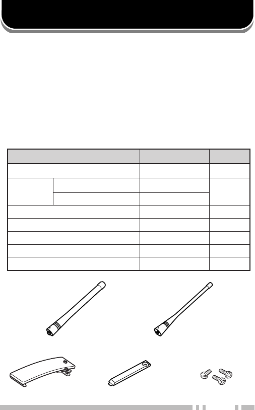
Supplied Accessories
Belt clip Universal connector cap Screw set
Antenna (TK-285) Antenna (TK-385)
metI rebmuNtraP ytitnauQ
)ylnoE(kcapyrettaBXX-0900-90W1
annetnA )ylnoE,K(582-KTXX-3370-09T 1
)ylnoM(582-KTXX-4370-09T
pilctleBXX-8560-92J1
pacrotcennoclarevinUXX-3630-90B1
teswercSXX-4002-99N1
)ylno3K,K(dracytnarraW––1
launamnoitcurtsnIXX-4621-26B1
2
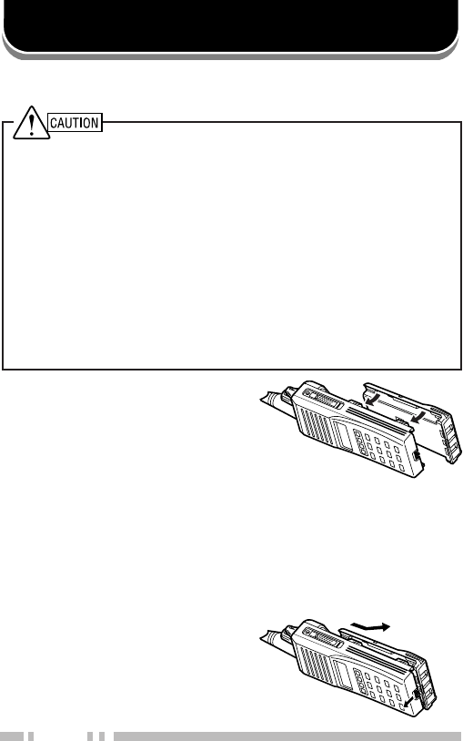
PREPARATION
1Match the four grooves of
the battery pack with the
corresponding guides on
the back of the transceiver.
2Slide the battery pack along
the back of the transceiver
until the release latch on
the base of the transceiver
locks.
3To remove the battery pack,
pull back on the release
latch and slide the pack
away from the transceiver.
Installing/ Removing the (Optional) NiCd Battery Pack
◆
DO NOT RECHARGE THE BATTERY PACK IF IT IS ALREADY
FULLY CHARGED. DOING SO MAY CAUSE THE LIFE OF THE
BATTERY PACK TO SHORTEN OR THE BATTERY PACK MAY
BE DAMAGED.
◆
AFTER RECHARGING THE BATTERY PACK, DISCONNECT IT
FROM THE CHARGER. IF THE CHARGER POWER IS RESET
(TURNED ON AFTER BEING TURNED OFF), RECHARGING
WILL START AGAIN AND THE BATTERY PACK WILL BECOME
OVERCHARGED.
◆
DO NOT SHORT THE BATTERY TERMINALS OR DISPOSE
OF THE BATTERY BY FIRE.
◆
NEVER ATTEMPT TO REMOVE THE CASING FROM THE
BATTERY PACK.
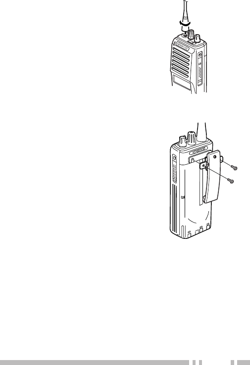
3
Screw the antenna into the
connector on the top of the
transceiver by holding the
antenna at its base and turning
it clockwise until secure.
Installing the Belt Clip
If necessary, attach the belt clip
using the two supplied
3 x 6 mm screws.
Note: If the belt clip is not installed, its
mounting location may get hot during
continuous transmission or when left
sitting in a hot environment.
Installing the Antenna
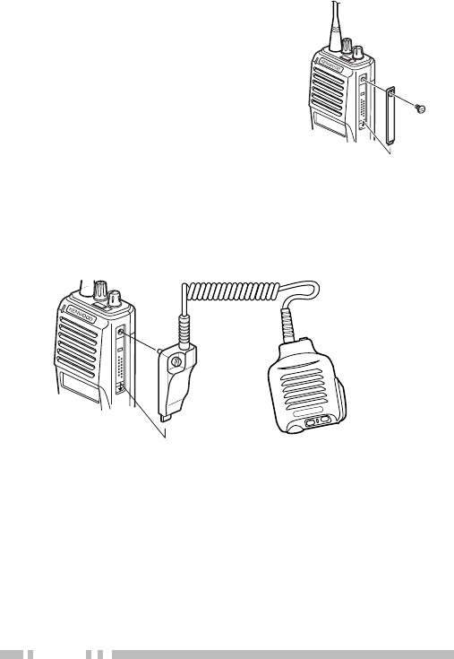
4
If you are not using the optional
KMC-25 speaker/ microphone,
install the cover over the
univeral connector using the
supplied 4 x 6 mm screw.
Installing the Cover over the Universal Connector
Installing the (Optional KMC-25) Speaker/ Microphone
1Insert the guide of the speaker/ microphone
connector into the groove of the universal connector.
2Secure the connector in place using the attached
screw.
5
eqw
r
t
o
!5
!0
!4
i
u
y
!1
!2
!3
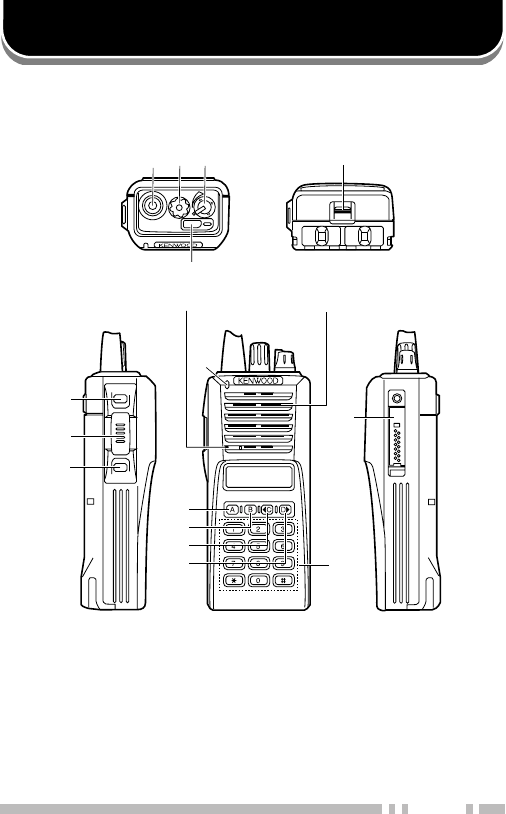
THE BASICS
Microphone Speaker
qq
qq
qAntenna connector
Connect the supplied antenna here.
ww
ww
wRotary encoder
ee
ee
ePOWER switch/ VOLUME control
Turn clockwise to switch ON the transceiver. Rotate
to adjust the volume. Turn counterclockwise fully to
switch OFF the transceiver.
Note: Features listed in this section are available for both Trunking and
Conventional modes. Mode specific features can be found in their
corresponding sections in this manual.

6
rr
rr
rAuxiliary (orange) key
tt
tt
tBattery pack release latch
Pull back on this latch to release the battery pack.
See “Installing/ Removing the (Optional) NiCd
Battery Pack” on page 2.
yy
yy
yCall key
uu
uu
uPTT (Push-To-Talk) switch
ii
ii
iClear key
oo
oo
oTransmit/ Receive indicator
!0!0
!0!0
!0 A key
!1!1
!1!1
!1 B key
!2!2
!2!2
!2 C key
!3!3
!3!3
!3 D key
!4!4
!4!4
!4 DTMF keypad
!5!5
!5!5
!5 Universal connector
Connect the (optional KMC-25) speaker/ microphone
here. Otherwise, keep the supplied cover in place.
■Switching Power ON/ OFF
Turn the Power switch/ Volume control clockwise to
switch the transceiver ON. The power on text or unit
number appears for 2 seconds.
Turn the Power switch/ Volume control
counterclockwise to switch the transceiver OFF.
■Adjusting the Volume
Rotate the Power switch/ Volume control to adjust
the volume. Clockwise increases the volume and
counterclockwise decreases it.

7
Key Functions
Note: The numbers correspond to the diagram on page 5.
ww
ww
wRotary encoder
Rotate this encoder to select your desired call
address (voice calls) or status (status calls).
rr
rr
rAuxiliary (orange) key (default setting: None)
Press to activate its auxiliary function {page 8}.
yy
yy
yCall key
Press to call the displayed call address.
uu
uu
uPTT (Push-To-Talk) switch
Press to transmit. Also press to initiate a call if “PTT
to Initiate Call” has been programmed.
ii
ii
iClear key
Press to end the current call.
oo
oo
oTransmit indicator
Lights red while transmitting.
!0!0
!0!0
!0 A key (default setting: Status/ Stack)
Press to activate its auxiliary function {page 8}.
!1!1
!1!1
!1 B key (default setting: Redial)
Press to activate its auxiliary function {page 8}.
!2!2
!2!2
!2 C key (default setting: Home)
Press to activate its auxiliary function {page 8}. Also
press to scroll left while viewing stack entries.
!3!3
!3!3
!3 D key (default setting: None)
Press to activate its auxiliary function {page 8}. Also
press to scroll right while viewing stack entries.
!4!4
!4!4
!4 DTMF keypad
Press to input a call address or dialing function.
TRUNKING MODE
8
Programmable Auxiliary Functions
The Auxiliary, A, B, C, and D keys can be
programmed with the auxiliary functions listed below.
Contact your dealer for details on these functions.
Note: Some of these functions cannot be programmed onto certain
keys. Ask your dealer for details.
• AUX A • Network Select
• Conventional • None
• Dialing • Redial
• Emergency • Scrambler
• Home • Status/ Stack
• Key Lock
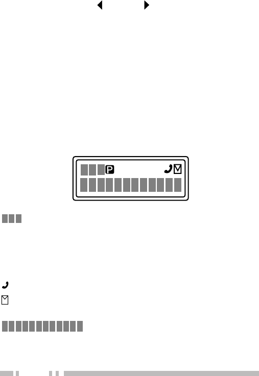
Display
SVC
MON SCN LO
displays the strength of received signals, the
output power (high or low), status numbers, and
received call types.
SVC
appears when a control channel is found. It flashes
while the transceiver is searching for a control channel.
flashes when you activate call diversion.
appears while there is data in the stack. It flashes
when there is new data in the stack.
displays call addresses, the call
duration timer, data messages, and the current
operating status of the transceiver.

9
Searching for a Control Channel
After switching the power ON, press any key while the
power on text or unit number is displayed to begin
searching for a control channel. Or, wait for
2 seconds to allow the transceiver to start searching for
a control channel automatically.
• The
SVC
indicator flashes and an arrow scrolls across the
display while the transceiver is searching for a control
channel.
Voice Calls
■Making a Voice Call
1Select a call address using one of the following
four methods:
i)
Select a call address from memory:
Select
your desired call address using the Rotary
encoder if a call address has been stored in
the transceiver memory.
ii)
Use a pre-programmed key:
Press key A, B,
C, or D to select a call address if they have
been pre-programmed with call addresses.
iii)
Select a call address from the stack:
Use a
received voice call from the stack as a call
address (refer to “Viewing the Stack”, on
page 14).
iv)
Enter a call address using the keypad:
Enter
your desired call address using the DTMF
keypad (keys 0 ~ 9,, and #). Refer to the
appendix {page 20} for the available dial
strings and control codes.

10
2Initiate the call, depending on how you selected
the call address.
i, ii, and iii (of step 1):
When selecting a call address from memory or
the stack, press the Call key (or the PTT switch if
“PTT to Initiate Call” has been programmed) to
initiate the call.
iv (of step 1):
When using MPT1343 dialing, press the # key to
initiate the call.
• “Calling” appears on the display.
3When the call is connected, a timer appears on
the display.
• The timer can be set up to either count up
(increasing number) or count down (decreasing
number).
4Press the PTT switch to transmit; release it to
receive.
• The LED lights red while transmitting.
• The 3-digit sub-display shows your transmit power.
A single triangle (▲) represents low power while
dual triangles (▲▲) represents high power.
5Press the Clear key to end the call. If the call
time expires before you press the Clear key, the
call will be automatically terminated.
• “END” momentarily appears on the display before
returning to the call address of the call you just
made.

11
■Receiving a Voice Call
1When a call is received, the caller’s unit number
appears on the main display and “CAL” appears
on the 3-digit sub-display.
• If you have the caller’s address set up in your
transceiver, the call address is displayed instead of
the unit number.
• Group conference calls are represented by “GRP”
rather than “CAL”. Group broadcast calls are
represented by “BCC”.
• Special calls are denoted as follows:
I-Fleet:
A call from a different fleet (Inter Fleet).
I-Prefix:
A call from a different prefix (Inter Prefix).
PABX:
A call from a PABX telephone system.
PSTN:
A call from a PSTN telephone system.
2Press the PTT switch to respond to the call.
• The remaining call time appears on the display.
3When the call ends, the display returns to the call
address which was previously displayed.
However, if you end the call by pressing the Clear
key, “END” momentarily appears on the display
before returning to the call address.

12
Status Calls
■Making a Status Call
1Select a call address using one of the following
two methods:
i)
Select a call address from memory:
Select
your desired call address using the Rotary
encoder if a call address has been stored in
the transceiver memory.
ii)
Enter a call address using the keypad:
Enter
your desired call address using the DTMF
keypad (keys 0 ~ 9,, and #). Refer to the
appendix {page 20} for the available dial
strings and control codes.
2Press the Status/ Stack key (default is the A
key), then rotate the Rotary encoder to select
your desired status.
• The status number appears on the 3-digit
sub-display.
3Press the Call key (or PTT switch if “PTT to
Initiate Call” is programmed in the transceiver) to
send the status.
• “Calling” appears on the display.
4When the status has been received by the called
party, “Complete” momentarily appears on the
display before returning to the call address of the
call you just made.

13
■Receiving a Status/Short Data Message Call
1When a call is received, the indicator appears
on the display and flashes.
• The indicator remains on the display when there
is data in the stack.
2To view the status or message, refer to “Viewing
the Stack”, on page 14.
Call Displays
The following messages may appear on the display
under certain circumstances:
Holding:
The transceiver is confirming the call made by
the base station.
Engaged:
The called party is in another call.
Queued:
All communication channels are currently in
use; your status will be sent when a channel becomes
free.
Fail:
The control station received an invallid call.
NU:
You entered an invallid call address.
No Reply:
The called party has been called, but they
did not respond to the call.
Call Back:
The called party has set their transceiver to
queue all incoming calls.
Sys Busy:
The system is currently busy.

14
Viewing the Stack
1Press the Status/ Stack key (default is the A key)
twice to enter the stack.
• If there is no data in the stack, “------------” appears on
the main display and “-00” appears on the 3-digit
sub-display.
2Rotate the Rotary encoder to view the stack entries.
• “NEW” represents a new entry, “S” represents a status
stack entry, “V” represents a voice stack entry, and “D”
represents a data stack entry.
3Press the C and D keys to scroll through the
selected entry, to view the entire entry.
4To erase an entry, select the desired entry and press
the Clear key.
Call Diversions
■Diverting Your Own Calls
1Enter control code “ 41”.
2Press the key, then enter the unit number
where you want to divert the calls.
3Press the # or Call key.
• “Calling” appears on the display. While your
request is being processed, “Holding” appears on
the display. When the call divert is set, “Complete”
momentarily appears on the display before
returning to the previously selected call address.
The indicator appears on the display and flashes.

15
4To end the call diversion, enter control code
“#41”, then press the # or Call key.
• “Calling” appears on the display. While your
request is being processed, “Holding” appears on
the display. When the call divert is cleared,
“Complete” momentarily appears on the display
before returning to the previously selected call
address.
■Diverting Third Party Calls
1Enter control code “ 44”.
2Press the key, then enter the unit number of the
transceiver which you want to divert the calls.
2Press the key, then enter the unit number
where you want to divert the calls.
3Press the # or Call key.
• “Calling” appears on the display. While your
request is being processed, “Holding” appears on
the display. When the call divert is set, “Complete”
momentarily appears on the display before
returning to the previously selected call address.
4To end the call diversion, enter control code
“#44”, press the key, enter the unit number of
the transceiver whose calls are being diverted,
then press the # or Call key.
• “Calling” appears on the display. While your
request is being processed, “Holding” appears on
the display. When the call divert is cleared,
“Complete” momentarily appears on the display
before returning to the previously selected call
address.

16
CONVENTIONAL MODE
Key Functions
Note: The numbers correspond to the diagram on page 5.
ww
ww
wRotary encoder
Rotate this encoder to select your desired channel.
yy
yy
yCall key
Press to turn the squelch OFF in order to monitor
your selected channel.
uu
uu
uPTT (Push-To-Talk) switch
Press this switch, then speak into the microphone to
call a station.
ii
ii
iClear key
Press to return to Trunking mode.
oo
oo
oReceive indicator
Lights green while receiving a signal.
!0!0
!0!0
!0 A key
Press to turn Scan ON (or OFF).
!1!1
!1!1
!1 B key
Press to add/remove channels to/from Scan.
!3!3
!3!3
!3 D key
Press to turn the display and keypad backlight ON.
The backlight remains ON for 5 seconds.

17
Display
SVC
MON SCN LO
displays the strength of received signals.
MON
appears while you are monitoring a channel by
pressing the Call key.
SCN
appears while you are scanning.
displays channel numbers and the
current operating status of the transceiver.
Entering Conventional Mode
Depending on how your transceiver is programmed, you
can enter Conventional mode in one of two ways:
Manual:
Press the key programmed as Conventional
to change the operating mode.
Auto:
The transceiver automatically changes to
Conventional mode when you are outside the network
area.

18
Returning to Trunking Mode
Depending on how your transceiver is programmed, you
can return to Trunking mode in one of three ways:
Manual:
Press the Clear key to change the operating
mode.
Auto:
While in Conventional mode, the transceiver
periodically searches for the network. When it finds the
network, the transceiver automatically changes to
Trunking mode. An alert tone sounds to notify you when
the operating mode changes.
Alert:
While in Conventional mode, the transceiver
periodically searches for the network. When it finds the
network, an alert tone sounds. Press the Clear key to
change the operating mode.
Conventional Mode Operation
1Rotate the Rotary encoder to select your desired
channel.
2Press the Call key to turn squelch OFF in order to
monitor any activity on the channel.
• The
MON
indicator appears on the display.
• The LED lights green and you will hear background
noise.
3Press the PTT switch to transmit; release it to
receive.

19
Scanning
Press the A key to turn Scan ON (or OFF).
While scanning, the
SCN
indicator and “-SCAN-” appear
on the display.
When a call is received, scanning stops and the channel
number appears. Press the PTT switch and speak into
the microphone to respond to the call. The transceiver
will continue scanning after an adjustable time delay if
the PTT switch is released and no further signal is
received.
Only channels added to the scanning sequence will be
scanned. Channels which are added to the scanning
sequence all have an add indicator ( ▼ ) in the left-most
segment of the main display.
To add a channel to the scanning sequence, select the
desired channel, then press the B key.
•▼ appears on the display.
To remove a channel from the scanning sequence,
select the desired channel, then press the B key.
•▼ no longer appears on the display.
Lamp
To light up the display and keypad, press the D key.
The lamp will remain ON for approximately 5 seconds.
20
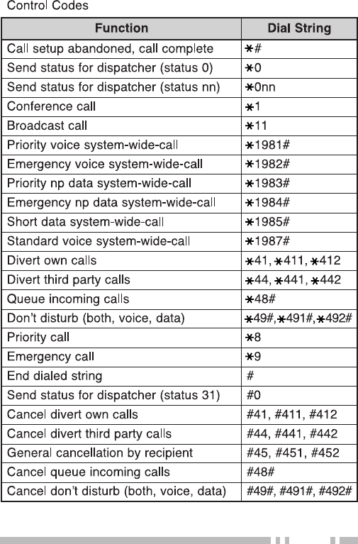
APPENDIX
gnilaiDtigiD2
noitcnuF gnirtSlaiD
rebmunlaudividnI98~02
rebmunpuorG99~09
gnilaiDtigiD3
noitcnuF gnirtSlaiD
rebmunlaudividnI998~002
rebmunpuorG899~009
rotarepoycnegremE999
slennahcnepoehtretnE011~101
secivresrotarepokrowteN ,151,141,131,121,111,001 191,181,171,161
gnilaiDtigiD4
noitcnuF gnirtSlaiD
llacXBAP9998~0001
gnilaiDtigiD5
noitcnuF gnirtSlaiD
sserddaelgniS(llacXBAP )sllacdrow dnoceS+)6~3(gnirtstsriF )9998~0001(gnirts
dednetxE(llacXBAP )locotorpgnisserdda +)8ro,7,0(gnirtstsriF )9999~0000(gnirtsdnoceS

21
gnilaiDtigiD6
noitcnuF gnirtSlaiD
teelf-retnIxiferpnommoC llaclaudividni +)0506~1002(#teelF )98~02(#laudividnI
teelf-retnIxiferpnommoC llacpuorg +)0506~1002(#teelF )99~09(#puorG
dednetxe(llacXBAP )locotorpgnisserdda
+)8ro,7,0(gnirtstsriF ~00000(gnirtsdnoceS )99999
gnilaiDtigiD7
noitcnuF gnirtSlaiD
teelf-retnIxiferpnommoC llaclaudividni +)0506~1002(#teelF )998~002(#laudividnI
teelf-retnIxiferpnommoC llacpuorg +)0506~1002(#teelF )899~009(#puorG
dednetxe(llacXBAP )locotorpgnisserdda
+)8ro,7,0(gnirtstsriF ~000000(gnirtsdnoceS )999999
gnilaiDtigiD8
noitcnuF gnirtSlaiD
llacNTSP dnoceS+)0(gnirtstsriF )9999999~0000000(gnirts
dednetxe(llacXBAP )locotorpgnisserdda dnoceS+)8ro7(gnirtstsriF )9999999~0000000(gnirts

22
gnilaiDtigiD9
noitcnuF gnirtSlaiD
teelf-retnIxiferp-retnI llaclaudividni
+)723~002(#xiferP +)0506~1002(#teelF )98~02(#laudividnI
puorgteelf-retnIxiferp-retnI llac
+)723~002(#xiferP +)0506~1002(#teelF )99~09(#puorG
llacNTSP dnoceS+)0(gnirtstsriF gnirts
)99999999~00000000(
dednetxe(llacXBAP )locotorpgnisserdda dnoceS+)8ro7(gnirtstsriF gnirts
)99999999~00000000(
gnilaiDtigiD01
noitcnuF gnirtSlaiD
teelf-retnIxiferp-retnI llaclaudividni
+)723~002(#xiferP +)0506~1002(#teelF )998~002(#laudividnI
puorgteelf-retnIxiferp-retnI llac
+)723~002(#xiferP +)0506~1002(#teelF )899~009(#puorG
llacNTSP dnoceS+)0(gnirtstsriF gnirts
)999999999~000000000(
gnilaiDtigiD11
noitcnuF gnirtSlaiD
llacNTSP dnoceS+)0(gnirtstsriF gnirts
)9999999999~0000000000(
23